

Page 1

Form No.
SL3640, SL3840
and SL4240
Skid-Steer
Loaders
917170
Revision A
01/06
Service Manual
®
Page 2

INTRODUCTION
With correct maintenance and proper use, Gehl skid-steer loaders will give years of dependable service. This service
manual is intended to be a guide in the assembly and disassembly, installation and removal, adjustment and testing,
troubleshooting and replacement of components that together make up the Gehl SL3640/3840/4240 family of
skid-steer loaders.
In many of the procedures found within, the installation steps are the exact opposite of the removal steps and vice
versa, and therefore, the opposite procedure is not written. Instead,a note to reverse the procedure will be stated.This
reduces redundancy and excessive pages in the manual. In cases though, where the assembly and disassembly or
removal and installation procedures differ and additional steps or safety concerns are paramount, the entire reverse
procedure will be written out to include the new information.
The Table of Contents and Index can be used to make the procedure you need to find an easier process. Also, there are
black tabs extending off the pages highlighting the chapters for those who prefer to thumb through the manual. Many
schematics, photographs, and line art drawings are used to help perform the necessary repairs, tests, or adjustments
that the SL3640/3840/4240 skid-steer loaders need to keep them in good running condition.
If you have any additional questions, please contact your authorized Gehl dealer or call the Gehl Service Department
for assistance.
Gehl is a registered trademark of the Gehl Company.
Page 3

SL3640/3840/4240 TABLE OF CONTENTS
TABLE OF CONTENTS
Specifications Page 1-1
Specifications ······································································1-1
Tire Options ·······································································1-1
Buckets and Capacities ······························································1-1
General Specifications ·······························································1-2
Safety Page 2-1
General Information ·································································2-1
Signal Words ······································································2-1
Additional Safety Reminders ··························································2-1
Mandatory Safety Shutdown Procedure ·················································2-2
Liftarm Support Device ······························································2-3
Liftarm Support Device Engagement ···················································2-3
Liftarm Support Device Disengagement ·················································2-4
Rollover Protective Structure (ROPS) - Raising ···········································2-4
Rollover Protective Structure (ROPS) - Lowering ·········································2-5
Relieving Hydraulic Pressure··························································2-6
Skid-Steer Loader Raising Procedure ···················································2-6
Skid Loader Lowering Procedure ······················································2-7
Lubrication Page 3-1
General Information ·································································3-1
Hydraulic Oil Reservoir ······························································3-1
Crankcase Oil ······································································3-2
Hydraulic Oil Tank Drain Procedure ····················································3-2
Chaincases········································································3-3
Chaincase Oil Change Procedure·······················································3-3
Grease Fitting Locations ·····························································3-3
Cooling System Drain Procedure·······················································3-4
PRINTED IN USA i 917170/AP0106
Page 4

TABLE OF CONTENTS SL3640/3840/4240
Mainframe Page 4-1
Introduction ·······································································4-1
Engine Access Cover Removal and Installation ···········································4-2
Rollover Protective Structure (ROPS) Removal and Installation ······························4-2
Seat Removal and Installation ·························································4-4
Seat Slide Replacement ······························································4-4
Rollover Protective Structure (ROPS) Rear Window Removal and Installation ··················4-5
Restraint Bar Removal and Installation ··················································4-7
All-Tach™ Bracket Removal and Installation·············································4-9
Liftarm Removal and Installation ······················································4-10
Liftarm Bushing Replacement ·························································4-13
Liftarm Stop Installation and Adjustment ················································4-14
Floor Cover and Kick Plate Removal and Installation ······································4-16
Fuel Level Sender Removal and Installation ··············································4-19
Rear Grille Removal and Installation····················································4-20
Wheel Drives Page 5-1
Introduction ·······································································5-1
Drive Chain Adjustment ·····························································5-2
Drive Chain Removal and Installation···················································5-3
Axle Removal and Installation·························································5-4
Controls Page 6-1
Introduction ·······································································6-1
Control Handle Removal and Installation ················································6-6
Control Handle Position and Tracking Adjustment·········································6-7
Dual Control Weldment Removal and Installation - T-Bar Controls ···························6-9
Neutral Centering Device and Pump Arm Removal and Installation ···························6-10
Neutral Centering Device Adjustment···················································6-11
Lift/Tilt Control Removal and Installation ···············································6-12
Lift/Tilt Control Adjustment ··························································6-13
Auxiliary Hydraulics Removal and Installation ···········································6-14
Auxiliary Hydraulics Adjustment ······················································6-15
Hand Throttle, Hand Throttle Cable and Throttle Rod Removal and Installation ·················6-16
Foot Throttle and Foot Throttle Cable Removal and Installation - T-Bar Controls ················6-18
Hand Throttle Adjustment ····························································6-19
Hand Throttle Tension Adjustment ·····················································6-20
Foot Throttle Adjustment - T-Bar Controls ···············································6-21
917170/AP0106 ii PRINTED IN USA
Page 5

SL3640/3840/4240 TABLE OF CONTENTS
Hydrostatic System Page 7-1
Introduction ·······································································7-1
Troubleshooting Guide·······························································7-3
Charge Pressure Test and Adjustment ···················································7-7
Hydrostatic Pump Relief Valves ·······················································7-8
Drive Motor Hot Oil Shuttle Valve ·····················································7-8
Hydrostatic Pump Removal and Installation ··············································7-9
Hydrostatic Pump Flexible Drive Plate Removal and Installation ·····························7-11
Drive Motor Removal and Installation ··················································7-12
Hydraulic System Page 8-1
Introduction ·······································································8-1
Troubleshooting Guide·······························································8-3
System Pressure Test - Control Valve ···················································8-7
Tilt Cylinder Test ···································································8-9
Self-Leveling Valve Test ·····························································8-11
Self-Leveling Valve Adjustment ·······················································8-12
Lift Cylinder Test···································································8-13
Solenoid Valve Test ·································································8-14
Hydraulic Oil Filter Element Replacement ···············································8-16
Tilt Cylinder Removal and Installation ··················································8-19
Lift Cylinder Removal and Installation ··················································8-21
Lift and Tilt Cylinder Disassembly and Assembly ·········································8-23
Gear Pump Removal and Installation ···················································8-24
Self-Leveling Valve Removal and Installation ············································8-26
Safety Lock Valves - Removal and Installation ···········································8-27
Lift, Tilt and Brake Safety Lock Valves - Disassembly and Assembly ·························8-29
Control Valve Removal and Installation ·················································8-30
Hydraulic/Hydrostatic System Schematic ················································8-32
All-Tach is a trademark of the Gehl Company.
PRINTED IN USA iii 917170/AP0106
Page 6

TABLE OF CONTENTS SL3640/3840/4240
Electrical System Page 9-1
Description of Operation ·····························································9-1
Troubleshooting Guide·······························································9-4
Relay Test and Operation·····························································9-6
Electrical Circuits···································································9-8
Seat Switch Removal and Installation ···················································9-15
Restraint Bar Switch Removal and Installation ············································9-16
Front and Rear Work Light Bulb Replacement ············································9-17
Electrical System Schematic ··························································9-18
Engine Page 10-1
Introduction ·······································································10-1
Troubleshooting Guide·······························································10-2
Engine Oil Filter Element Removal and Installation········································10-4
Air Cleaner Assembly Removal and Installation···········································10-7
Air Filter Element Removal and Installation ··············································10-7
Fuel Filter Removal and Installation ····················································10-8
Water Separator Element Removal and Installation ········································10-8
Electric Fuel Pump Removal and Installation ·············································10-9
Priming Diesel Fuel System···························································10-9
Battery Removal and Installation·······················································10-10
Starter Removal and Installation ·······················································10-11
Exhaust Assembly Removal and Installation ·············································10-11
Fan Belt Adjustment ································································10-12
Radiator/Cooler Removal and Installation················································10-15
Fan Shroud Removal and Installation - 4240 Models ·······································10-16
Fuel Tank Removal and Installation ····················································10-17
Engine Removal and Installation ·······················································10-19
Index
917170/AP0106 iv PRINTED IN USA
Page 7

SL3640/3840/4240 SPECIFICATIONS
SPECIFICATIONS
Engine Make Yanmar Yanmar
Model 3TNV88-XMS2 4TNV88-XMS2
Fuel Diesel Diesel
Displacement 100 CID (1,64 L) 133 CID (2,19 L)
Horsepower - Net (SAE) 35 hp (26 kW) @ 2600 rpm 46 hp (34 kW) @ 2600 rpm
Torque - Maximum 80 ft.-lbs. (108,5 N•m) @ 1200 rpm 103 ft.-lbs. (139,7 N•m) @ 1200 rpm
Rated Operating Load (SAE)* 1050 lbs. (476 kg) 1350 lbs. (612 kg)
Operating Weight 4000 lbs. (1814 kg) 4600 lbs. (2087 kg)
Shipping Weight 3515 lbs. (1594 kg) 4065 lbs. (1844 kg)
Engine Oil 7.6 US qts. (7,2 L) 9.1 US qts. (8,6 L)
Fuel Tank 10.3 US gal. (39 L) 12.4 US gal. (47 L)
Standard Flow Rate 14.5 gpm (55 L/min) 16.5 gpm (62 L/min)
Travel Speed (max) 6.4 mph (10,3 km/h) 6.8 mph (10,9 km/h)
Specifications below apply to all 3640, 3840 and 4240 models
Chaincases (each) 8.0 US qts. (7,6 L)
Hydraulic Reservoir 8.0 US gal. (30 L)
Battery 12-volt DC, 675 CCA
Starter 12-volt DC (2.0 kW)
Alternator 40 A
Main Hydraulic System Pressure 2750 psi (190 bar)
SL3640/3840 SL4240
SPECIFICATIONS
Capacities
Electrical
Hydraulic System
Tire Options
7 x 15 SS Narrow
8.5 x 15 - 8 ply Heavy-Duty Flotation
10.50 x 15 - 8 ply Heavy-Duty Flotation
10 x 16.5 - 6 ply Standard Flotation
10 x 16.5 - 8 ply Heavy-Duty Flotation/Foam-Filled
10 x 16.5 - 10 ply Severe-Duty/Severe-Duty Foam-Filled
6.5 x 16 Solid Rubber
Buckets and Capacities
Width Description Capacity (Heaped)
48 inches (1219 mm) Dirt/Construction 9.75 cubic feet 0,27 cubic meters
48 inches (1219 mm) Utility 11.9 cubic feet 0,34 cubic meters
54 inches (1372 mm) Dirt/Construction 9.5 cubic feet 0,27 cubic meters
54 inches (1372 mm) Utility 13.5 cubic feet 0,38 cubic meters
55 inches (1397 mm) Dirt/Construction 10.5 cubic feet 0,30 cubic meters
60 inches (1524 mm) Utility 15.2 cubic feet 0,43 cubic meters
61 inches (1550 mm) Dirt/Construction 11.7 cubic feet 0,33 cubic meters
61.5 inches (1562 mm) Low Profile 12.6 cubic feet 0,36 cubic meters
61.5 inches (1562 mm) Earth & Foundry 13.0 cubic feet 0,37 cubic meters
61.5 inches (1562 mm) Construction 13.0 cubic feet 0,37 cubic meters
3640/3840 SAE Rated Operating Load: Operating load rated with a 54" (1372 mm) dirt/construction bucket in accordance with SAE J818.
4240 SAE Rated Operating Load: Operating load rated with a 60" (1524 mm) dirt/construction bucket in accordance with SAE J818.
PRINTED IN USA 1-1 917170/AP0106
Page 8
SPECIFICATIONS SL3640/3840/4240
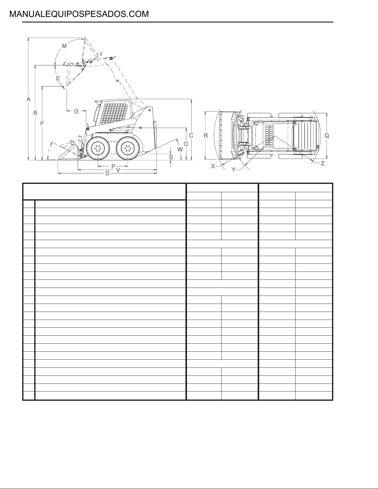
General Specifications
A Overall operation height - fully raised 139.6 3546 141.1 3584
B Height to hinge pin - fully raised 108.1 2746 110 2794
C Overall height - top of ROPS 70.3 1786 71.9 1826
D Overall length (w/54” dirt/construction bucket down) 114.5 2908
Overall length (w/60” dirt/construction bucket down) 116.2 2952
E Dump angle @ full height 42° 42°
F Dump height (w/54” dirt/construction bucket) 84.5 2146
Dump height (w/60” dirt/construction bucket) 86.5 2197
G Dump reach - w/54” dirt/construction bucket (full height) 22.8 578
Dump reach - w/60” dirt/construction bucket (full height) 20.6 523
I Rollback at ground 29° 29°
M Rollback at full height 99° 99°
O Seat-to-ground height 32.6 828 33.6 853
P Wheelbase 34.5 876 36.7 932
Q Overall width - no bucket (w/27 x 8.5 x 15 tires) 48.4/58.2 1229/1428
Overall width - no bucket (w/10 x 16.5 tires) 52.5/58.4 1334/1483
R Overall bucket width - 54” dirt/construction bucket 55.3 1403
Overall bucket width - 60” dirt/construction bucket 60.6 1539
S Ground clearance to mainframe (between wheels) 6 152 8.3 211
V Overall length (no bucket) 88.9 2258 91.1 2314
W Departure angle 26° 29°
X Clearance circle - front (w/54” dirt/construction bucket) 69.4 1763
Clearance circle - front (w/60” utility bucket) 69.2 1758
Y Clearance circle - front (no bucket) 44.1 1120 43.4 1102
Z Clearance circle - rear 54.1 1374 58.4 1484
SL3640/3840 (1) SL4240 (2)
inches millimeters inches millimeters
(1) Dimensions with 27 x 8.50 x 15 HD tires and 54” bucket.
(2) Dimensions with 10.00 x 16.5 HD tires and 60” bucket.
917170/AP0106 1-2 PRINTED IN USA
Page 9

SL3640/3840/4240 SAFETY
General Information
Signal Words
DANGER
“DANGER” indicates an imminently
hazardous situation which, if not avoided,
will result in death or serious injury.
The above safety alert symbol means: ATTENTION!
BECOME ALERT! YOUR SAFETY IS INVOLVED!
It stresses an attitude of “Heads Up for Safety” and can
be found throughout this service manual and on the
decals on the machine.
Before operating or working on this machine, read and
study the following safety information. In addition, be
sure that everyone who operates or works on this
equipment is familiar with these safety precautions. It is
essential to have competent and careful operators, who
are not physically or mentally impaired, and who are
thoroughly trained in the safe operation of the machine
and the handling of loads. It is recommended that the
operator be capable of obtaining a valid motor vehicle
operator’s license.
The use ofskid-steer loaders is subject tocertain hazards
that cannot be eliminated bymechanical means, but only
by exercising intelligence, care and common sense.
Such hazards include, but are not limited to, hillside
operation, overloading, instability of the load, poor
maintenance and using the equipment for a purpose for
which it is not intended or designed.
The Gehl Company ALWAYS considers the operator’s
safety when designing its machinery and guards
exposed moving parts for the operator’s protection.
However, some areas cannot be guarded or shielded in
order to assure proper operation. Furthermore, the
Operator’s Manual and the decals on the machine warn
of additional hazards and should be read and observed
closely.
These topics in this chapter include procedures, which,
when followed, will allow safe performance of service
procedures: Mandatory Safety Shutdown Procedure,
Lift Cylinder Liftarm Support Device, Roll-Over
Protective Structure (ROPS)/Falling Object Protective
Structure (FOPS) LockMechanism, Loader Raising and
Lowering Procedures, and Relieving Hydraulic
Pressure.
SAFETY
WARNING
“WARNING” indicates a potentially
hazardous situation which, if not avoided,
could result in death or serious injury.
CAUTION
“CAUTION” indicates a potentially
hazardous situation which, if not avoided,
may result in minor or moderate injury. May
also alert against unsafe practices.
Additional Safety Reminders
Read and understand the Service Manual
and all decals before maintaining, adjusting
or servicing this equipment.
Doors, Guards and Shields - Some
photographs in this manual may show doors, guards and
shields open or removed for illustrative purposes only.
BE SURE all doors, guards and shields are in their
proper operating positions BEFORE starting engine to
operate unit.
Damaged or Worn-out Parts - For safe operation,
replace damaged or worn-out parts with genuine Gehl
service parts, BEFORE operating this equipment.
Attachments - Gehl skid-steer loaders are designed and
intended to be used only with Gehl Company
attachments or approved referral attachments. The Gehl
Company cannot be responsible for operator safety if the
loader is used with a non-approved attachment.
Battery Safety - To avoid injury from a
spark or short circuit, disconnect the
negative (-) battery cable before servicing
any part of the electrical system. Do not
tip the battery more than 45º to avoid spilling electrolyte.
PRINTED IN USA 2-1 917170/AP0106
Page 10

SAFETY SL3640/3840/4240
Loader Stability - A skid-steer loader’s stability is
determined by its wheelbase and tread width. The
following elements can affect stability: terrain, engine
speed, load being carried or dumped, and sudden control
movements.
DISREGARDING ANY OF THESE FACTORS CAN
CAUSE THE LOADER TO TIP, POSSIBLY
RESULTING IN DEATH OR SERIOUS INJURY.
Therefore, ALWAYS have the operator restraint bar
lowered and wearthe seat belt.Operate the controlsonly
from the operator’s seat. Operate the controls smoothly
and gradually at an appropriate engine speed that
matches the operating conditions.
DO NOT exceed the rated operating load of the
machine. For additional stability when operating on
inclines or ramps, ALWAYS travel with the heavier end
of the loader toward the top of the incline.
ALWAYS look to the rear before backing up.
When parking machine, before leaving seat, check
restraint bar for proper operation. The restraint bar,
when raised, applies the parking brake and deactivates
lift/tilt controls and auxiliary hydraulics.
Keyswitch - NEVER attempt to bypass the keyswitch to
start the engine. Use the jump-starting procedure
detailed in the Service chapter of the Operator’s Manual.
Hydraulic Fluid Leaks - NEVER use
hands to search for hydraulic fluid leaks.
Instead, use paper or cardboard. Fluid under
pressure can be invisible, penetrate the skin
and cause a serious injury. If any fluid is injected into
skin, see a doctor at once. Injected fluid MUST be
surgically removed by a doctor or gangrene may result.
DO NOT drive too close to an excavation or ditch. BE
SURE that the surrounding ground has adequate
strength to support the weight of the loader and the load.
DO NOT smoke or have any
spark-producing equipment in the area
while filling the fuel tank or while working
on the fuel or hydraulic systems.
Exhaust Gases - Exhaust fumes can kill. DO NOT
operate this machine in an enclosed area unless there is
adequate ventilation.
Engine - NEVER use ether or starting fluid.
People - NEVER carry riders. DO NOT allow others to
ride on the machine or attachment, because they could
fall or cause an accident.
BE SURE all persons are away from the machine and
give a warning before starting the engine.
ALWAYS face machine and use handholds and steps
when getting on or off. DO NOT jump off machine.
Wear appropriate ear protection for
prolonged exposure to excessive noise.
ALWAYS perform a daily inspection of the
machine BEFORE using it. Look for
damage, loose or missing parts, leaks, etc.
Remove trash and debris from the machine and engine
compartment each day to minimize risk of fire.
New operators MUST operate loader in an open area
away from bystanders. Practice with controls until
loader can be operated safely and efficiently.
Mandatory Safety Shutdown Procedure
Wear Safety Glasses - ALWAYS wear
safety glasses with side shields when
operating the machine or striking metal
against metal. In addition, it is
recommended that a softer (chip-resistant) material be
used to cushion the blow. Failure to heed could lead to
serious injury to eye(s) or other parts of the body.
ALWAYS wear safety glasses when searching for
hydraulic leaks or when working near batteries.
Loaded Bucket/Fork - DO NOT raise or drop a loaded
bucket or fork suddenly. Abrupt movements under load
can cause serious loader instability.
NEVER push the lift control into the “float” position
with the bucket or attachment loaded or raised, because
this will cause the liftarm to lower rapidly.
917170/AP0106 2-2 PRINTED IN USA
BEFORE cleaning, adjusting, lubricating, or
servicing the unit or leaving it unattended:
1. Move the drive control handle(s) to the
NEUTRAL position.
2. Lower the liftarm and attachment completely.
3. Move the throttle to the low idle position, shut off
the engine and remove the key.
4. However, if the liftarm MUST be left in the
“raised” position, BE SURE to properly engage the
liftarm support device.
Only after these precautions can you be sure it is
safe to proceed. Failure to follow the above
procedure could lead to death or serious injury.
Page 11

SL3640/3840/4240 SAFETY
Fig. 2-1 The lock pin secures the liftarm support device
inside the left liftarm to a welded pin.
Liftarm Support Device
WARNING
BEFORE leaving the operator’s compartment
to work on the loader with the liftarm raised,
ALWAYS engage the liftarm support device.
Turn the keyswitch to OFF, remove the key
and take it with you.
Many service procedures require a raised liftarm to
allow easier access to loader components. For operator
and service personnel safety, a liftarm support device is
standard on Gehl skid-steer loaders. Used as a cylinder
block, it helps prevent a raised liftarm from lowering
unexpectedly.
BE SURE to engage the liftarm support device
whenever the liftarm is raised. When the device is not
being used, secure it tothe anchor on theunderside of the
liftarm using the lock pin and retainer provided.
SAFETY
Fig. 2-2 Pull down and pull out on the lock pin to
release the liftarm support device.
The liftarm support device is a safety device which must
be kept in proper operating condition at ALL times.
The following procedures outline the correct way to
engage and disengage the liftarm support device.
Liftarm Support Device Engagement
1. Lower liftarm until contact with loader frame.
2. Turn the keyswitch to the OFF position to stop the
engine.
3. Leave the operator’s compartment. Pull down on
lock pin button to release its locking mechanism.
Pull out lock pin holding support device up against
liftarm. Allow support device to come down into
contact with lift cylinder. Figs. 2-1, 2-2, 2-3
4. Return to the operator’scompartment and restart the
engine.
5. Use lift control to raise liftarm until the lift arm
support device drops over the end of the lift cylinder
and around cylinder rod. Slowly lower liftarm until
the free end of the support device contacts the top
(rod end) of the lift cylinder. Fig. 2-4
6. Make sure the support device is secure against the
Fig. 2-3 The liftarm support device rests on top of the
lift cylinder base.
PRINTED IN USA 2-3 917170/AP0106
cylinder end. Then, stop the engine, remove the key
and leave the operator’s compartment.
Page 12

SAFETY SL3640/3840/4240
Liftarm Support Device Disengagement
WARNING
NEVER leave the operator’s compartment to
disengage the liftarm support device with the
engine running.
To return the liftarm support device to its storage
position, proceed as follows:
1. Raise liftarm completely.
2. Turn keyswitch to OFF position to stop engine,
remove key and take it with you.
WARNING
BEFORE testing the machine, ALWAYS clear
people from the area.
3. Before leaving operator’s compartment, check to
make sure liftarm is being held in the raised position
by the solenoid valve.
NOTE: With the keyswitch OFF, and the solenoid
valve working, the liftarm will stay raised when the lift
control is moved forward. If the valve does NOT hold
the liftarm and it begins to lower, do NOT leave the
operator’s compartment. Instead, have someone store
the support device for you. Then, contact your Gehl
dealer to determine the reason why the liftarm lowers
while the keyswitch is in the OFF position.
4. To store liftarm support device, lift it up and inside
the liftarm. Insert lock pin through hole in welded
lock pin below the support device. Figs. 2-1, 2-2
Fig. 2-4 Lower liftarm until liftarm support device
contacts the rod end of the lift cylinder.
Fig. 2-5 Front left ROPS mounting area where the
ROPS is secured to the chassis. Right side
same.
ROPS – Raising
For service, the ROPS can be unbolted and tilted back.
Gas-charged springs help tilt it back. A self-actuating
lock mechanism engages to lock the ROPS in a
rolled-back position.
1. The liftarm shouldbe lowered or lockedin the raised
position as per the “Liftarm Support Device
Engagement” procedure in this chapter.
2. Turn the keyswitch to the OFF position to stop the
engine. Remove the key and take it with you.
3. Leave the operator’s compartment.
917170/AP0106 2-4 PRINTED IN USA
Fig. 2-6 Use wrenches to release the front of the ROPS
from the chassis.
Page 13

SL3640/3840/4240 SAFETY
WARNING
DO NOT leave the operator’s compartment
with the engine running. Before leaving the
loader, shut off the engine according to the
“Mandatory Safety Shutdown Procedure”
described in this chapter.
SAFETY
4. Remove two capscrews, six flat washers and two
locknuts securing the ROPS front uprights to the
chassis. Figs. 2-5, 2-6
Fig. 2-7 Location of the self-actuating lock mechanism.
Fig. 2-8 Lowering the ROPS is a two-person operation.
5. Lift ROPS up and tilt it back until the self-actuating
lock mechanism engages. The lock mechanism
locks the ROPS in a rolled-back position. Fig. 2-7
IMPORTANT
BEFORE raising the ROPS, position the seat
as far back as it will go. Avoid damaging
control handles by slowly raising the ROPS.
BE SURE the control handles clear theROPS.
ROPS – Lowering
1. With an assistant's help, apply upward force on the
ROPS while the assistant pulls the lock mechanism
handle toward the front of the loader. Fig. 2-8
2. Lower ROPS until it contacts the chassis. Fig. 2-9
IMPORTANT
Avoid damaging control handles by slowly
lowering the ROPS. BE SURE the control
handles clear the ROPS.
3. Reinstall the two capscrews, six flat washers and
two locknuts that secure the ROPS front uprights to
the chassis. Figs. 2-5, 2-6
Fig. 2-9 BE SURE the ROPS/FOPS clears the control
handles.
PRINTED IN USA 2-5 917170/AP0106
Page 14

SAFETY SL3640/3840/4240
Relieving Hydraulic Pressure
The following procedure should be used to relieve
pressure in the hydraulic system prior to performing
service procedures on hydraulic system components.
1. Completely lower the bucket or attachment.
2. Turn keyswitch to OFF position to shut down
engine.
3. With the operator in the seat and the restraint bar
lowered, turn the keyswitch to the ON position, but
DO NOT start the engine.
4. Move the lift, tilt and auxiliary hydraulics controls
through several cycles. Figs. 2-10, 2-11
5. Turn the keyswitch to the OFF position.
Skid-Steer Loader Raising Procedure
The following procedure is used to raise the skid-steer
loader so that all four tires ARE NOT contacting the
ground.
Lift and Tilt
Auxiliary Hydraulics
Fig. 2-10 On Hand/Foot control models, the lift and tilt
functions are controlled with the foot pedals on
the floor of the ROPS. The auxiliary hydraulics
are controlled by the right control handle.
Auxiliary Hydraulics
Lift and Tilt
WARNING
BEFORE servicing the machine, exercise the
“Mandatory Safety Shutdown Procedure”
described in this chapter.
WARNING
DO NOT rely on a jack or hoist to maintain the
“raised” position without additional blocking
and supports. Serious personal injury could
result from improperly raising or blocking the
skid-steer loader.
1. To raise and block the skid-steer loader, obtain four
jack stands or wooden blocks of sufficient strength
to support the loader.
2. Using a jack or hoist capable of raising the
fully-equipped loader, lift rear of loader until tires
are off the ground. Fig. 2-13
3. Place two jack stands under theflat part of the loader
chassis. Place them parallel with, but not touching,
the rear tires. Fig. 2-14
Fig. 2-11 On T-Bar control models, lift and tilt functions
are controlled with the right control handle.
The auxiliary hydraulics are controlled with
the left foot on the auxiliary hydraulics pedal.
4. Slowly lower loader so its weight rests on the jack
stands or the wooden blocks.
917170/AP0106 2-6 PRINTED IN USA
Page 15

SL3640/3840/4240 SAFETY
5. Repeat steps 2-4 for the front end. When the
procedure is finished, all four tires will be off the
ground, and they can be removed as necessary.
Tie Down Support
Stand Placement Location
Fig. 2-12 View of the jack stand placement area and tie
down support locations.
Skid-Steer Loader Lowering Procedure
When service procedures are complete, the skid-steer
loader can be taken down from the “raised” position. To
lower the loader onto its tires:
1. Using a jack or hoist, raise front of loader until its
weight no longer rests on the jack stands.
2. Carefully remove jack stands or wooden blocks
under front of loader.
3. Slowly lower loaderuntil front tires areon ground.
4. Repeat steps 1-3 for rear of loader.
SAFETY
Fig. 2-13 Locations underneath the skid-steer loader to
position jack stands or blocks at the front and
rear. (View is from the rear of the loader.)
Fig. 2-14 View of jack stands supporting right rear of
skid-steer loader.
PRINTED IN USA 2-7 917170/AP0106
Page 16

SAFETY SL3640/3840/4240
NOTES
917170/AP0106 2-8 PRINTED IN USA
Page 17

SL3640/3840/4240 LUBRICATION
3
2
General Information
WARNING
NEVER service this unit when any part of the
machine is in motion. ALWAYS BE SURE to
exercise the MANDATORY SAFETY
SHUTDOWN PROCEDURE (see Safety
chapter) BEFORE servicing this equipment.
1
Fig. 3-1 Hydraulic oil fill and dipstick (1), hydraulic
filter (2) and engine oil dipstick (43).
Fig. 3-2 Hydraulic oil drain plug located behind the left
rear tire.
Routine lubrication is an important factor in preventing
excessive part wear and early failure. Loader and engine
operation depends on using correct grade, high-quality
lubricating oils. This chapter and the chart below list
locations, temperature ranges and type of recommended
lubricants to be used when servicing this machine. In
addition, refer to the engine manual for specific grades
and ratings as specified by the engine manufacturer.
NOTE: Whenever service is performed on hydraulic
components (valves, cylinders, hoses, etc.), fuel tanks
and lines, care must be taken to prevent discharging
fluid onto the ground. Catch and dispose of fluid per
local waste disposal regulations.
Hydraulic Oil Reservoir
The oil reservoir for hydraulic and hydrostatic systems
has a capacityof eight U.S. gallons (30 liters). A dipstick
built into the reservoir cap provides a visual oil level
indicator (Fig. 3-1) for convenient maintenance of the
hydraulic oil level.
LUBRICATION
Hydraulic System
Reservoir
Use a Petro-Canada
Premium HVI60, or
equivalent which contains
anti-rust, anti-foam, and
anti-oxidation additives &
conforms to ISO VG46.
Capacity:
8 Gallons (30 L)
PRINTED IN USA 3-1 917170/AP0106
Chaincases
Use hydraulic system oil
or SAE grade 15W-40
motor oil.
Capacity (each side):
8 Quarts (7,6 L)
Grease
Fittings
Use lithium-based grease.
Crankcase Oil
(Diesel Engine)
µ Below 32°F (0°C) use
SAE Grade* 10 or 10W-30
µ Above 32°F (0°C) use
SAE Grade* 15W-40
*Service Classification:
API - CF-4/SH
Capacity:
7.6 Quarts (7,2 L) 36/3840
9.1 Quarts (8,6 L) 4240
Antifreeze
Coolant System
Add a mixture of 50%
water, 50% ethylene
glycol to the recovery
tank if coolant level in
recovery tank is low.
Page 18

LUBRICATION SL3640/3840/4240
The hydraulic oil reservoir should be drained (Fig. 3-2)
and filled after every 1000 hours of operation or
annually (whichever occurs first). Use
PETRO-CANADA hydraulic oil (or ISO VG46
equivalent) which contains anti-rust, anti-foam and
anti-oxidation additives. Hydraulic oil filter element
should be replaced after every 500 hours of operation
(See NOTE). For details, refer to “Hydraulic Oil Filter
Element Replacement” procedure in Hydraulic chapter.
NOTE: An initial 50-hour hydraulic oil filter element
replacement is recommended for new skid-steer
loaders.
Hydraulic Oil Tank Drain Procedure
1. Open engine access cover and rear grille.
2. Because the tank is pressurized, slowly remove
hydraulic oil tank cap from filler neck at left side
riser. Fig. 3-1
3. Underneath the left riser, remove drain plug on
hydraulic oil tank. Place a suitable container under
drain plug hole to catch hydraulic oil. Fig. 3-2
5
4
2
1
3
Fig. 3-3 Location of the engine oil filter (1), oil fill (2),
oil drain - not shown (3), dipstick (4) and fuel
filter (5) on left side of engine.
NOTE: Care must betaken to prevent discharging fluid
onto the ground. Catch and dispose of fluid per local
waste disposal regulations.
Crankcase Oil
The Yanmar diesel engine crankcase has a capacity of
7.6 quarts (7,2 L) for 36/3840 skid-steers or 9.1 quarts
(8,6 L) for 4240 skid-steers. The chart below lists
recommended oil viscosity for the engine.
Engine oil should be changed and the filter element
replaced every 250 hours of service. Refer to the engine
operator’s manual (see NOTE) for details on changing
oil and to the “Oil Filter Removal and Installation”
procedure in the Engine chapter. Figs. 3-3, 3-4, 3-5
NOTE: Refer to engine operator’s manual for
additional information on oil change intervals,
including a 50-hour initial oil change interval.
Ambient Temperature Viscosity
Fig. 3-4 Oil filter access location, underneath loader,
near left rear tire.
2
1
Below 32°F (0°C) SAE 10 or 10W-30
Above 32°F (0°C) SAE 15W-40
Fig. 3-5 Location of engine oil fill (1) and oil dipstick
Service classification: API-CF-4/SH
917170/AP0106 3-2 PRINTED IN USA
(2).
Page 19

SL3640/3840/4240 LUBRICATION
Liftarm
Chaincases
Each chaincase requires 8.0 quarts (7,6 L) of SAE motor
oil. This quantity of oilshould be maintained atall times.
The oil in both chaincases should be drained and refilled
every 1000 hours (See NOTE) of operation or annually,
whichever occurs first.
NOTE: A initial 50-hour chaincase oil change is
recommended.
Change Chaincase Oil Procedure
Raise the rear of the loader off the ground following the
“Loader Raising” procedure in this manual.
Fig. 3-6 Location of left chaincase drain plug; right side
is the same. To facilitate draining, lift rear of
loader slightly with a suitable hoist or jack.
Fig. 3-7 Location of chaincase oil fill/check plug.
1. Remove drain plugs and drain oil into a suitable
container. Fig. 3-6
NOTE: Care must betaken to prevent discharging fluid
onto the ground. Catch and dispose of fluid per local
waste disposal regulations.
2. Reinstall drain plugs.
3. Remove fill/level check plug. Fig. 3-7
4. Lower the rear of the loader to return loader to a
level position.
5. Add oil through fill/level check plug until oil starts
to flow out of check plug. Fig. 3-7
6. Reinstall fill/level check plug.
Grease Fitting Locations
Use lithium-based grease on allgrease fittings. Figs. 3-8
through 3-11
Grease every 10 hours of operation (or daily)
LUBRICATION
1. Grease liftarm pivots.
2. Grease lift cylinder pivots.
3. Grease tilt cylinder pivots.
4. Grease All-Tach™ attachment pivots.
Fig. 3-8 Liftarm grease fitting locations.
PRINTED IN USA 3-3 917170/AP0106
Page 20

LUBRICATION SL3640/3840/4240
Cooling System Drain Procedure
Gehl SL36/38/4240 skid-steer loaders use a radiator/
cooler to help keep the engine from overheating. Some
procedures in this Service Manual require partially or
fully draining the radiator/cooler for those procedures.
Coolant / Hydraulic Oil - Drain Procedure
WARNING
BEFORE beginning this service procedure,
perform the following SAFETY procedure:
Shut off the engine and allow to cool.
q
(For detailed instructions, refer to the Safety
chapter of this manual.)
1. Open engine access cover and rear grille.
2. Remove radiator cap.
3. A drain cock is located at bottom rear of radiator.
Open drain cock and drain coolant into a suitable
container. Fig. 3-12
4. Open small access cover (belly pan) located in
chassis behind radiator/cooler, placing a suitable
container underneath the opening.
5. Use two wrenches on lower oil cooler hose (to
prevent damage to fitting), remove lower hose and
drain oil through access cover. Fig. 3-12
NOTE: Care must betaken to prevent discharging fluid
onto the ground. Catch and dispose of fluid per local
waste disposal regulations.
6. Close drain cock, reinstall lower oil cooler hose.
Fig. 3-10 Lower tilt cylinder grease fitting location.
Fig. 3-11 Rod-end lift cylinder grease fitting location.
Radiator Cap
Radiator Side
Fig. 3-12 Radiator/Cooler system drain locations. Left
arrow indicates the radiator drain cock
Fig. 3-9 Attachment bracket grease fitting locations.
917170/AP0106 3-4 PRINTED IN USA
location, the right arrow indicates the lower oil
cooler radiator hose.
Oil Cooler Side
Page 21

SL3640/3840/4240 MAINFRAME
Introduction
Gehl SL36/38/4240 skid-steer loaders have a welded
steel mainframe. Maintenance, service and repair can be
performed through standard access panels. The left rear
mainframe riser serves as the hydraulic reservoir. A
welded steel tank bolted to the mainframe behind the
ROPS/FOPS serves as the fuel tank.
Two side cases provide mounting for the drive motors
and for the front and rear axles. The side cases also serve
Oil is used inside thesecases to ensure the chains always
receive proper lubrication.
The liftarm and the lift and tilt cylinders are mounted
with pivot pins. Capscrews are used to secure the pivot
pins. A Rollover Protective Structure/Falling Object
Protective Structure (ROPS/FOPS) is standard for
operator safety, and both the seat and restraint bar
include safety interlock switches.
as sealed housings for the drive chains and sprockets.
Rollover & Falling Object Protective Structure (ROPS/FOPS) Components
48
45
46
56 11
19
26 5 27
55
8
30
57
50
54
36
37 38
51
13
17
14
24
12
43
44
35
23 22
58
9
21
1
3
4
2
18
33
44 FOAM/SIDE RIGHT
45 GASKET/TOP WINDOW
46 GASKET/TOP WINDOW
47 SPONGE RUBBER/SEAT PLATE
48 WINDOW/TOP
49 SCREW/MACHINE
50 SCREW/CAP
51 SCREW/CAP
47
28
45
53 8 56
46
41
39
40
49
42
32
52 SCREW/CAP
53 SCREW/CAP
54 SCREW/CAP
55 BOLT/CARRIAGE
56 SCREW/MACHINE
57 WASHER/FLAT
58 WASHER/FLAT
29
2 BOLT/SHOULDER
3 BOLT/SHOULDER
4 BUSHING/OILITE
5 TETHER
1 BOLT/SHOULDER
15
6 WASHER/FLAT
51
7 MOUNTING/ISOLATOR
8 NUT/SPEED
9 NUT/LOCK NYLON INSERT
10 NUT/HEX
11 NUT/LOCK SERRATED
12 NUT/LOCK
3452
7
6
34
10
5631
13 NUT/LOCK
14 NUT/LOCK
15 ISOLATOR/ROPS
16 SCREW/WHIZLOCK
17 SUPPORT/ROPS
18 LATCH/ROPS
19 BRACKET/DOME LIGHT
20 ROPS/FOPS
20
16
21 BUSHING
22 TAG/RIP CORD
23 RING
24 GAS SPRING/ROPS
25 HANDLE/GRAB
25
26 NUT/FLAT
27 NUT/SPECIAL
16
28 SCREW/MACHINE
29 PANEL/INSTRUMENT LEFT
30 SHIELD/HARNESS
31 PLATE/HEATER SEAL
32 COVER/SEAT PLATE
33 SPRING/EXTENSION
34 WASHER/FLAT
35 STRIP/LOCKING
36 HOLDER/MANUAL
37 WINDOW/REAR
38 SEAL/WINDOW
39 FOAM/HEADLINER
40 FOAM/REAR PANEL
41 FOAM/SIDE LEFT
42 FOAM/SIDE LEFT
43 FOAM/SIDE RIGHT
MAINFRAME
Fig. 4-1 Assembly view of ROPS/FOPS components.
PRINTED IN USA 4-1 917170/AP0106
Page 22

MAINFRAME SL3640/3840/4240
Engine Access Cover Removal and
Installation
WARNING
BEFORE beginning this service procedure,
perform the following SAFETY procedures:
Shut off the engine.
q
(For detailed instructions, refer to the Safety
chapter of this manual.)
Removal Procedure
1. Open engine access cover until gas spring is
completely extended.
2. Disconnect gas spring from engine access cover by
removing gas spring clip with a small screwdriver,
then pull gas spring off ball stud on access cover.
Lower engine access cover. Fig. 4-2
3. Remove two locknuts securing engine access cover
to ROPS bolt/mainframe and remove cover. Fig.
4-3
Installation Procedure - Follow all warnings first,
then reverse the removal steps.
Spring Clip
Fig. 4-2 Engine access cover gas spring attached to ball
stud on engine access cover.
ROPS Bolt
ROPS Removal and Installation
WARNING
BEFORE beginning this service procedure,
perform the following SAFETY procedures.
q
Shut off the engine.
(For detailed instructions, refer to the Safety
chapter of this manual.)
Removal Procedure
1. Remove the engine access cover per the procedure
in this chapter.
2. Disconnect negative (-) battery cable from battery.
3. Disconnect ROPS wiring harness connector,
secured to mainframe, at right of fuel tank. Also,
disconnect ROPS power connector at same
location. Fig. 4-4
Fig. 4-3 One of two locknuts on ROPS bolt securing
the engine access cover to the mainframe.
Fig. 4-4 The harness bulkhead is where the harness
assembly meets the instrument panel harness.
Remove harness at front of bulkhead.
917170/AP0106 4-2 PRINTED IN USA
Page 23

SL3640/3840/4240 MAINFRAME
Fig. 4-5 Right side gas spring on the ROPS.
4. Raise ROPS per the procedure found in the Safety
chapter.
5. With ROPS tilted back and locked, attach a hoist so
that it is supporting the weight of the ROPS.
WARNING
The hoist MUST BE situated precisely above
the ROPS or else performing the following
steps may cause the ROPS to swing as the
bolts are removed. This could cause serious
bodily injury and/or damage the loader.
6. On right side of ROPS, remove one capscrew and
locknut securing gas spring to ROPS. Fig. 4-5
7. Disassemble ROPS lock mechanism by removing
shoulder bolt and locknut from welded hinge on
ROPS. Remove limiter assembly from ROPS. Fig.
4-6
MAINFRAME
Fig. 4-6 Location of shoulder bolt to remove on the
ROPS lock mechanism.
8. Carefully remove two capscrews and locknuts
securing rear of ROPS to mainframe. Figs. 4-7 and
4-8
9. Lift ROPS off loader.
Installation Procedure - Follow all warnings first,
then reverse the removal steps.
Fig. 4-7 Capscrew through riser where the ROPS
connects to the mainframe.
PRINTED IN USA 4-3 917170/AP0106
Fig. 4-8 Capscrew through riser where the ROPS
connects to the mainframe.
Page 24

MAINFRAME SL3640/3840/4240
Seat Removal and Installation
WARNING
BEFORE beginning this service procedure,
perform the following SAFETY procedures:
Raise liftarm; engage liftarm support
q
device.
Shut off the engine.
q
Tilt back ROPS until lock engages.
q
(For detailed instructions, refer to the Safety
chapter of this manual.)
Removal Procedure
1. Remove four nuts from studs attaching seat to seat
pan underneath ROPS. Fig. 4-9
Fig. 4-9 Location of four nuts securing seat to seat pan.
2. Release lock mechanism and lower ROPS.
Disconnect seat switch from wiring harness. Figs.
4-10, 4-11
3. Lift seat from seat pan.
Installation Procedure - Follow all warnings first,
then reverse the removal steps.
Seat Slide Replacement
Replacement Procedure
1. Remove seat per the procedure in this chapter.
2. Remove four capscrews and flat washers attaching
seat slide to seat. Fig. 4-10
3. Replace with new slides using existing capscrews
and flat washers.
Seat Switch
Seat Pan
Seat Slide
Fig. 4-10 Front seat slide capscrews shown.
Seat
Seat Switch
Fig. 4-11 Seat switch connected to wiring harness,
behind the seat.
917170/AP0106 4-4 PRINTED IN USA
Page 25

Page 26

®
Gehl Company 143 Water Street, P.O. Box 179, West Bend, WI 53095-0179 USA
www.gehl.com
917170/AP0106 © 2006 GEHL COMPANY PRINTED IN USA
All Rights Reserved.
 Loading...