

Page 1
Form No.
907389
1639/1649
PowerBox
Self Propelled
Paver
Discount-Equipment.com
OPERATOR’S MANUAL
www.discount-equipment.com
Page 2

Discount-Equipment.com is your online resource for commercial and industrial
Discount-Equipment.com
quality parts and equipment sales.
Locations:
Florida (West Palm Beach): 561-964-4949
Outside Florida TOLL FREE: 877-690-3101
Need parts? Check out our website at www.discount-equipment.com
Can’t find what you need?
Click on this link: http://www.discount-equipment.com/category/5443-parts/ and fill out
the request form.
Please have the machine model and serial number available in order to help us get
you the correct parts. One of our experienced staff members will get back to you with
a quote for the right part that your machine needs.
We sell worldwide for the br
Diamond
Chicago Pneumatic, Allmand Brothers, Essick, Miller Spreader, Skyjack, Lull, Skytrak,
Tsurumi, Husquvarna/Target, Whiteman-Concrete/Mortar, Stow-Concrete/Mortar, Baldor,
Wacker, Sakai, Snorkel, Upright, Mi-T-M, Sullair, Neal, Basic, Dynapac, MBW, Weber,
Bartell, Bennar Newman, Haulotte, Ditch Runner, Blaw-Knox, Himoinsa, Best, Buddy,
Crown, Edco, Wyco, Bomag, Laymor, Terremite, Barreto, EZ Trench, Takeuchi, Basic, Bil-
Jax, Curtis, Gehl, Heli, Honda, ICS/PowerGrit, Puckett, Waldon, ASV, IHI, Partner, Imer,
Clipper, MMD, Koshin, Rice, Gorman Rupp, CH&E, Cat Pumps, Comet, General Pump,
Giant,AMida, Coleman, NAC, Gradall, Square Shooter, Kent, Stanley, Tamco, Toku, Hatz,
Kohler, Robin, Wisconsin, Northrock, Oztec, Toker TK, Rol-Air, Small Line, Wanco, Yanmar
Products, Magnum, Airman, Mustang, Power Blanket, Nifty Lift, Atlas Copco,
ands: Genie, Terex, JLG, MultiQuip, Mayco, Toro/Stone,
Page 3

Table of Contents
Chapter Description Page
Warranty . . . . . . . . . . . . . . . . . . . . . . . . . . . . . . . . . . . . .Inside Front Cover
1 Introduction . . . . . . . . . . . . . . . . . . . . . . . . . . . . . . . . . . . . . . . . . . . . . . . .1
2 Specifications . . . . . . . . . . . . . . . . . . . . . . . . . . . . . . . . . . . . . . . . . . . . . .4
3 Check Lists . . . . . . . . . . . . . . . . . . . . . . . . . . . . . . . . . . . . . . . . . . . . . . . .7
4 SAFETY . . . . . . . . . . . . . . . . . . . . . . . . . . . . . . . . . . . . . . . . . . . . . . . .10
5 Controls, Attachments & Accessories . . . . . . . . . . . . . . . . . . . . . . . . . . .16
6 Operation & Adjustments . . . . . . . . . . . . . . . . . . . . . . . . . . . . . . . . . . . .24
7 Lubrication . . . . . . . . . . . . . . . . . . . . . . . . . . . . . . . . . . . . . . . . . . . . . . .33
8 Trouble Shooting . . . . . . . . . . . . . . . . . . . . . . . . . . . . . . . . . . . . . . . . . .36
9 Service & Storage . . . . . . . . . . . . . . . . . . . . . . . . . . . . . . . . . . . . . . . . . .44
10 Decal Locations . . . . . . . . . . . . . . . . . . . . . . . . . . . . . . . . . . . . . . . . . . .58
11 Maintenance Log . . . . . . . . . . . . . . . . . . . . . . . . . . . . . . . . . . . . . . . . . .62
Index . . . . . . . . . . . . . . . . . . . . . . . . . . . . . . . . . . . . . . . . . . . . . . . . . . . .66
Standard Hardware Torque Data . . . . . . . . . . . . . . . . . . . . . . . . . . . . . . .68
International Symbols . . . . . . . . . . . . . . . . . . . . . . . . . . .Inside Back Cover
IDENTIFICATION INFORMATION
Write your Gehl PowerBox Model (1639, or 1649) and Serial Numbers in the space provided below.
Refer to these numbers when inquiring about parts or service from your Gehl dealer.
The Model and Serial Numbers for this machine are on a Decal located on the Backwall.
Printed In U.S.A. 1 907389/AP297
Discount-Equipment.com
Page 4

Chapter 1
INTRODUCTION
The information in this Operator’s Manual was written to give the owner/operator assistance in preparing, adjusting, maintaining and servicing of the Paver. More importantly, this manual provides an operating plan for safe and
proper use of the machine. Major points of safe operation are detailed in the SAFETY chapter of this manual. A
chart of standard hardware torques is located in the back of this manual.
The GEHL Company asks that you read and understand the contents of this manual COMPLETELY and
become familiar with your new machine, BEFORE attempting to operate it.
Throughout this manual, information is provided which is set in italic type and introduced by the word NOTE. Be
sure to read carefully and comply with the message or directive given. Following this information will improve
your operating or maintenance efficiency, help you to avoid breakdowns or damage and extend your machine’s
life.
A plastic container is provided on the unit for storing the Operator’s Manual. After using the Manual, please return
it to the container and keep it with the unit at all times! If this machine is resold, GEHL Company recommends
that this Manual be given to the new owner.
“Right” and “left” are determined from a position standing on the Screed Platform and facing forward.
Our wide Dealership network stands by to provide you with any assistance you may require, including genuine
GEHL service parts. All parts should be obtained from or ordered through your GEHL Dealer. Give complete
information about the part and include the model and serial numbers of your machine. Record the serial number
in the space provided on the previous page, as a handy record for quick reference.
GEHL Company reserves the right to make changes or improvements in the design or construction of any part
without incurring the obligation to install such changes on any unit previously delivered.
The GEHL Company, in cooperation with the
American Society of Agricultural Engineers and the
Society of Automotive Engineers, has adopted this
SAFETY ALERT SYMBOL
to pin point characteristics which, if NOT properly followed, can create a safety hazard. When you see
this symbol in this manual or on the machine itself,
you are reminded to BE ALERT! Your personal safey
is involved!
907389/AP297 2 Printed In U.S.A.
Discount-Equipment.com
Page 5

Paver Identification
LEFT HAND
CONTROL LEVERS
CONTROL
PANEL
MODULAR
STEERING
SCREED
HOPPER
BACK WALL
DRIVE TRACK
(EA. SIDE)
PROPANE
TANK
HYDRAULIC
RESERVOIR
(LOWER FRAME)
ENGINE &
HYD. PUMP
SCREED
ADJUST
SCREW
(EA. SIDE)
SPRAY
DOWN HOSE
(EA. SIDE)
RIGHT HAND
CONTROL LEVERS
Printed In U.S.A. 3 907389/AP297
Discount-Equipment.com
Page 6

Chapter 2
SPECIFICATIONS
Gehl PowerBox Paver Models: 1639 1649
General Dimensions:
Length . . . . . . . . . . . . . . . . . . . . . . . . . . . . . . . . . . . . . . . . . . . . . . . . . . . . . . . . 8 ft. 8 ft.
(2438 mm) (2438 mm)
Minimum Width (Transport) . . . . . . . . . . . . . . . . . . . . . . . . . . . . . . . . . . . . . . . 9 ft. 10 in. 9 ft. 10 in.
(2997 mm) (2997 mm)
Maximum Width (Operating) . . . . . . . . . . . . . . . . . . . . . . . . . . . . . . . . . . . . . . 9 ft. 10 in. 9 ft. 10 in.
(2997 mm) 2997 mm)
Overall Height . . . . . . . . . . . . . . . . . . . . . . . . . . . . . . . . . . . . . . . . . . . . . . . . . . 5 ft. 5 in. 5 ft. 5 in.
(1651 mm) 1651 mm)
Weight . . . . . . . . . . . . . . . . . . . . . . . . . . . . . . . . . . . . . . . . . . . . . . . . . . . . . . . . 8,395 lb. 8,460 lb.
(3803 kg) (3803 kg)
Truck Clearance (Height from ground to asphalt hopper floor) . . . . . . . . . . . . . 21 in. 21 in.
(533 mm) (533 mm)
Screed:
Maximum Variable Crown/Invert. . . . . . . . . . . . . . . . . . . . . . . . . . . . . . . . . . . . 2 in. 2 in.
(51 mm) (51 mm)
Width. . . . . . . . . . . . . . . . . . . . . . . . . . . . . . . . . . . . . . . . . . . . . . . . . . . . . . . . . 12 in. 12 in.
(305 mm) (305 mm)
Hydraulic Vibrator . . . . . . . . . . . . . . . . . . . . . . . . . . . . . . . . . . . . . . . . . . . . . . . Std. (83 Hz.) Std. 83 Hz.)
(5000 cy/min) (5000 cy/min)
Heat Medium (Exhaust). . . . . . . . . . . . . . . . . . . . . . . . . . . . . . . . . . . . . . . . . . . Standard Standard
Heat Medium (Propane). . . . . . . . . . . . . . . . . . . . . . . . . . . . . . . . . . . . . . . . . . . Optional Optional
Variable Hydraulic Strike Off Max. Extension Length . . . . . . . . . . . . . . . . . . . . 18 in. 18 in.
(457 mm) (457 mm)
Dual Span Operator Platform (Isolated) . . . . . . . . . . . . . . . . . . . . . . . . . . . . . . . Standard Standard
Service Capacities:
Engine Cooling System (Isuzu - 4LC1) . . . . . . . . . . . . . . . . . . . . . . . . . . . . . . . N/A 6.8 Qt.
(6.4 Liter)
Engine Oil w/Filter (Wisconsion - VH4D) . . . . . . . . . . . . . . . . . . . . . . . . . . . . . 4 Qt. N/A
(3.8 Liter)
Engine Oil w/Filter (Isuzu 4LC1). . . . . . . . . . . . . . . . . . . . . . . . . . . . . . . . . . . . N/A 6.9 qt.
(6.5 Liter)
907389/AP297 4 Printed In U.S.A.
Discount-Equipment.com
Page 7

SPECIFICATIONS (Continued)
Gehl PowerBox Paver Models: 1639 1649
Service Capacities (Continued):
Hydraulic Reservoir. . . . . . . . . . . . . . . . . . . . . . . . . . . . . . . . . . . . . . . . . . . . . . 20 Gal. 20 Gal.
(75.7 Liter) 75.7 Liter
Fuel Reservoir . . . . . . . . . . . . . . . . . . . . . . . . . . . . . . . . . . . . . . . . . . . . . . . . . . 12 Gal. 12 Gal.
45.4 Liter) (45.4 Liter)
Wash Down Tank w/Electric Pump . . . . . . . . . . . . . . . . . . . . . . . . . . . . . . . . . . 4.5 Gallons) 4.5 Gallons)
(17 Liter) (17 Liter)
Engine:
Wisconsin - VH4D, 30 HP (22.4 Kw) Gas, Air-Cooled, 12 Volt Electric Start,
30 Amp Alternator, 575 CCA Battery. . . . . . . . . . . . . . . . . . . . . . . . . . . . . . . . . Standard N/A
Isuzu - 4LC1, 41 HP (30.6 Kw) Diesel, Water-Cooled, 12 Volt Electric Start,
35 Amp Alternator, 575 CCA Battery. . . . . . . . . . . . . . . . . . . . . . . . . . . . . . . . . N/A Standard
Drive System:
Hydrostatic Steel Track Type, Single-Speed, Positive/Self-Adjusting
Counter-Rotating, Fine Tune Steering Valve. . . . . . . . . . . . . . . . . . . . . . . . . . . . Std. Std.
Maximum Ground Speed . . . . . . . . . . . . . . . . . . . . . . . . . . . . . . . . . . . . . . . . . . 130 FPM 130 FPM
(39.7 mpm) (39.7 mpm)
Hydraulic System:
Variable Hydrostatic Drive Pump - Maximum Flow. . . . . . . . . . . . . . . . . . . . . . 27 GPM 27 GPM
(102 Ltrs/M) (102 Ltrs/M)
Variable Hydrostatic Drive Pump - Maximum Relief Pressure . . . . . . . . . . . . . . 3500 PSI 3500 PSI
(24.5 Bar) (24.5 Bar)
Hydraulic Auger Drive Pump - Maximum Flow. . . . . . . . . . . . . . . . . . . . . . . . . 12 GPM 12 GPM
(45.4 Ltrs/M) (45.4 Ltrs/M)
Hydraulic Auger Drive Pump - Maximum Relief Pressure. . . . . . . . . . . . . . . . . 2000 PSI 2000 PSI
(14 Bar) (14 Bar)
Hydraulic Cylinder Pump - Maximum Flow . . . . . . . . . . . . . . . . . . . . . . . . . . . 12 GPM 12 GPM
(45.4 Ltrs/M) (45.4 Ltrs/M)
Hydraulic Cylinder Pump - Maximum Relief Pressure. . . . . . . . . . . . . . . . . . . . 1800 PSI 1800 PSI
(126 Bar) (126 Bar)
Return Filter . . . . . . . . . . . . . . . . . . . . . . . . . . . . . . . . . . . . . . . . . . . . . . . . . . . 5 Micron 5 Micron
Suction Strainer . . . . . . . . . . . . . . . . . . . . . . . . . . . . . . . . . . . . . . . . . . . . . . . . . 100 Micron 100 Micron
Aux. Oil Cooler Capacity . . . . . . . . . . . . . . . . . . . . . . . . . . . . . . . . . . . . . . . . . 12 GPM 12 GPM
(45.4 Ltrs/M) (45.4 Ltrs/M)
Printed In U.S.A. 5 907389/AP297
Discount-Equipment.com
Page 8

Gehl PowerBox Paver Models: 1639 1649
Paving Performance:
Minimum Variable Paving Width . . . . . . . . . . . . . . . . . . . . . . . . . . . . . . . . . . . . 4.5 ft. 4.5 ft.
(1372 mm) (1372 mm)
Maximum Variable Paving Width . . . . . . . . . . . . . . . . . . . . . . . . . . . . . . . . . . . 12 ft. 12 ft.
(3658 mm) (3658 mm)
Minimum Variable Paving Depth . . . . . . . . . . . . . . . . . . . . . . . . . . . . . . . . . . . . 0-1/2 in. 0-1/2 in.
(0-13 mm) (0-13 mm)
Maximum Variable Paving Depth . . . . . . . . . . . . . . . . . . . . . . . . . . . . . . . . . . . 6 in. 6 in.
(152.4 mm) (152.4 mm)
Gravity Feed Hopper Capacity. . . . . . . . . . . . . . . . . . . . . . . . . . . . . . . . . . . . . . 6 Ton 6 Ton
(5436 kg) (5436 kg)
Hydraulic Feed Augers . . . . . . . . . . . . . . . . . . . . . . . . . . . . . . . . . . . . . . . . . . . 2 2
Hydraulic Material Flow Gates . . . . . . . . . . . . . . . . . . . . . . . . . . . . . . . . . . . . . 2 2
Operating Speed . . . . . . . . . . . . . . . . . . . . . . . . . . . . . . . . . . . . . . . . . . . . . . . . 0-130 FPM 0-130 FPM
(0-40 mpm) (0-40 mpm)
Left and Right Side Operator Controls . . . . . . . . . . . . . . . . . . . . . . . . . . . . . . . . Standard Standard
SPECIFICATIONS (Continued)
907389/AP297 6 Printed In U.S.A.
Discount-Equipment.com
Page 9

Chapter 3
CHECKLISTS
PRE-DELIVERY
The following Checklist is an important reminder of valuable information and inspections which MUST be made
before delivering the Paver to the Customer. Check off each
item after prescribed action is taken.
Check that:
NO parts of Paver have been damaged in shipment. Check
for such things as dents and loose or missing parts; correct
or replace components as required.
Battery is securely mounted and NOT cracked. Cable con-
nections are tight. Electrolyte at proper level.
Cylinders, hoses and fittings are NOT damaged, leaking or
loosely secured.
Oil, fuel and air filters are NOT damaged leaking or loose-
ly secured.
All grease fittings have been properly lubricated and NO
fittings are missing; see Lubrication chapter of this manual.
Hydraulic system reservoir, engine crankcase, and engine
coolant are filled to the proper operating levels.
All adjustments have been made to comply with the set-
tings given in this manual and in the separate Engine manual.
All Guards, Shields and Decals are in place and securely
attached.
Model and Serial Number for this unit is recorded in space
provided on this page and page 1.
Start the Paver and test-run the unit while checking
that proper operation is exhibited by all controls.
Check that:
All indicator lamps, meters, etc. function properly.
Proper operation of all Hopper and Screed Controls.
Dynamic braking in effect with Drive Motors in neutral.
No hydraulic system leaks when under pressure.
Listen for abnormal noises or vibrations; if detected, deter-
mine their cause and repair as necessary.
I acknowledge that pre-delivery procedures were performed
on this unit as outlined above.
Dealership’s Name
Dealer Representative’s Name
Date Checklist filled-out
Paver Model# Paver Serial # Engine Serial #
DELIVERY
Check that:
The following Checklist is an important reminder of valuable information that MUST be passed on to the Customer at
the time the unit is delivered. Check off each item as you
explain it to the Customer.
Review with the Customer the contents of this manual;
especially:
The INDEX at the back, for quickly locating topics;
The SAFETY, CONTROLS/ATTACHMENTS & ACCES-
SORIES, and OPERATION/ADJUSTMENTS Chapters
for information regarding safe use of the machine.
The LUBRICATION, SERVICE and TROUBLESHOOT-
ING Chapters, for information regarding proper maintenance of the machine. Explain that regular lubrication and
maintenance are required for continued safe operation and
long life.
Give this Operator’s Manual to the Customer and instruct
the Customer to be sure to read and completely understand
its contents BEFORE operating the unit.
Explain that the Customer MUST consult the Engine
Manual (provided) for related specifications, operating
adjustments and maintenance instructions.
Completely fill out the Owner’s Registration, including
Customer’s signature and, return it to the company.
Customer’s Signature
Date Delivered
Printed In U.S.A. 7 907389/AP297
Discount-Equipment.com
Page 10

Chapter 4
SAFETY
The above Safety Alert Symbol means ATTENTION!
ALLWAYS BE ALERT! YOUR SAFETY IS
INVOLVED! It stresses an attitude of “Heads Up for
Safety” and can be found throughout this Operator’s
Manual and the machine itself.
BEFORE YOU ATTEMPT TO OPERATE THIS
EQUIPMENT READ AND STUDY THE FOLLOWING SAFETY INFORMATION. IN ADDITION, MAKE SURE THAT EVERY INDIVIDUAL WHO OPERATES OR WORKS WITH THIS
EQUIPMENT, WHETHER FAMILY MEMBER
OR EMPLOYEE, IS FAMILIAR WITH THESE
SAFETY PRECAUTIONS.
The Gehl Company ALWAYS takes the operator’s
safety into consideration when designing its machinery
and guards exposed moving parts for his/her protection. However, some areas can NOT be guarded or
shielded in order to assure proper operation. In addition, this Operator’s Manual and Decals
, on the
machine, warn of further danger and should be read and
observed closely.
REMEMBER! It is the owner’s responsibility for
communicating information on the safe use and proper
maintenance of this machine! This includes providing
understandable interpretation of these instructions for
operators who are not fluent in reading English.
MANDATORY SAFETY SHUTDOWN
PROCEDURE
BEFORE cleaning, adjusting, lubricating or servicing the unit:
1. Bring machine to full parking stop on level sur-
face (NEVER park on a slope or hill side).
2. Lower the Hopper and Screed Assembly to the
“full down” position.
3. Place controls in Neutral.
4. Move the Throttle to low idle.
5. Shut off the Engine and remove the Key.
ONLY when you have taken these precautions can
you be sure it is safe to proceed. Failure to follow
the above procedure, could lead to death or serious
bodily injury.
ADDITIONAL SAFETY REMINDERS
z USER/OPERATOR SAFETY PRACTICES, as
estabished by Industry Standards, are included in
this Operator’s Manual and intended to promote
SAFE OPERATION of the Paver. These guidelines do NOT preclude the use of good judgment,
care and common sense as may be indicated by the
particular jobsite work conditions.
z It is essential that operators be physically and men-
tally free of mind altering drugs and chemicals and
thoroughly trained in the safe operation of the
Paver. Such training should be presented completely to all new operators and not condensed for
those claiming previous experience. Information
on operator training is available from several
sources including the manufacturer.
DANGER
“DANGER” indicates an imminently hazardous situation which, if not avoided, will
result in death or serious injury.
WARNING
“WARNING” indicates a potentially hazardous
situation which, if not avoided, could result in
death or serious injury.
CAUTION
“CAUTION” indicates a potentially hazardous
situation which, if not avoided, may result in
minor or moderate injury. Also alerts to unsafe
practices.
907389/AP297 10 Printed In U.S.A.
Discount-Equipment.com
Page 11

SAFETY
(Continued)
z Some illustrations, used in this manual, may show
Doors, Guards and Shields open or removed for
illustration purposes ONLY. Be SURE that all
Doors, Guards and Shields are in their proper operating positions BEFORE starting the Engine to
operate the Paver.
z ALWAYS wear appropriate personal safety gear
called by the job or working conditions. Do NOT
wear loose or baggy clothing while operating or
servicing the machine.
z ALWAYS maintain safe clearance from electrical
powerlines and avoid contact with any electrically
charged conductor. Contact can result in electrocution. Contact proper local authorities for utility line
location BEFORE starting a job.
z ALWAYS check the job site for obstructions and
bystanders!
z NEVER use your hands to search for hydraulic
fluid leaks. Use a piece of paper or cardboard.
Escaping fluid under pressure can be invisible and
can penetrate the skin causing serious injury. If any
fluid is injected into your skin, see a doctor at
once. Injected fluid MUST be surgically removed
by a doctor familiar with this type of injury or gangrene may result!
z Do NOT attempt to move HOT asphalt mix with
your hands or feet. Contact can cause serious skin
burns!
z Do NOT allow minors or any unqualified person-
nel to operate or be near the Paver unless properly
supervised!
z Do NOT operate the Paver in an enclosed area
without adequate ventilation! Internal combustion
engines deplete the oxygen supply within enclosed
spaces and may create a serious hazard unless the
oxygen is replaced!
z Do NOT leave the Paver unattended with the
Engine running. ALWAYS lower the Hopper to
“full down” position, shut off the Engine and place
all controls in neutral BEFORE leaving the
machine!
z ALWAYS position the Safety Props when leaving
the Hopper raised for inspection, cleaning or service!
z Do NOT attempt to refill the Fuel Reservoir when
the Engine is hot. Allow Engine to cool down
BEFORE refilling to prevent hot Engine from
igniting the fuel if it should spill or splash!
z Do NOT smoke while filling the Fuel Reservoir,
while working on the fuel or hydraulic systems, or
while working around the Battery!
z Do NOT attempt to loosen or disconnect ANY
Hydraulic Lines, Hoses or Fittings without first
relieving hydraulic circuit pressure. Also, be careful NOT to touch any hydraulic components that
have been in recent operation because they can be
extremely HOT and can burn you!.
z ALWAYS disconnect the Battery connection to
prevent unintentional starting while working on
this machine!
z Do NOT attempt to remove the Radiator Cap after
the Engine has reached operating temperature or if
it is overheated. At operating temperatures, the
Engine Coolant will be extremely HOT and under
pressure. ALWAYS wait for the Engine to cool
down before attempting to relieve pressure and
remove the Radiator Cap. Failure to heed this
warning could result in severe burns!
z ALWAYS observe the following Safety
Procedures when Propane Screed Heater is used:
Wrench tighten all fittings. NEVER use grease or
lubrication. Do NOT use oxygen with the Heater.
Keep cylinder upright at all times. Keep equipment
free from dirt and oil.
Use a regulator on supply cylinder.
Check equipment carefully each time before lighting. ALWAYS light with a striker, NEVER with
matches. Do NOT operate in an enclosed area or
Printed In U.S.A. 11 907389/AP297
Discount-Equipment.com
Page 12
SAFETY
(Continued)
near flammable material. Close all valves when
not in use. Comply with all federal, state, and local
regulations when operating this equipment.
Screed Propane Heater - General Safety
1. This equipment is designed to be used only with
propane gas.
2. Wrench tighten all fittings.
3. NEVER use oil or grease for lubrication.
4. Do NOT use oxygen with this equipment.
S. Keep cylinder upright at all times.
6. Keep equipment free from dirt and oil.
7. Use a regulator on supply cylinder.
8. Check equipment carefully each time before lighting.
9. Always light with a striker, never with matches.
10. Do NOT operate in an enclosed area or near
flammable material.
11. Close all valves when not in use.
12. Comply with all federal, state and local regulations when operating this equipment.
z To ensure continued safe operation, replace dam-
aged or worn-out parts with genuine GEHL service
parts, BEFORE attempting to operate this equipment.
Modifications, Nameplates, Markings
And Capacities
z Modifications and additions, which affect capacity
or safe operation, shall NOT be performed without
the manufacturer’s prior written approval. Where
such authorization is granted, tags or decals shall
be changed accordingly.
Protective Guards And Warning
Devices
z The Paver is fitted with protective Covers over the
Engine area in accordance with Industry
Standards. They are intended to offer protection to
the operator from physical injury. A Horn is provided which can be activated from either side of
the Paver.
Replacement Parts
z To ensure continued safe operation, replace dam-
aged or worn-out parts with genuine GEHL service
parts, BEFORE attempting to operate this equipment.
CAUTION
Do NOT smoke in the area around the Power
Box Paver when equipped with Propane
Burners.
ALWAYS make sure a suitable fire extinguisher is readily available.
ALWAYS light burner with a striker, NEVER
use a match.
Burner flame may be invisible in sunlight. Do
NOT place burner near your skin or clothing.
Servere burns will result.
907389/AP297 12 Printed In U.S.A.
Discount-Equipment.com
Page 13
SAFETY
(Continued)
Printed In U.S.A. 13 907389/AP297
Discount-Equipment.com
Page 14
SAFETY
(Continued)
907389/AP297 14 Printed In U.S.A.
Discount-Equipment.com
Page 15
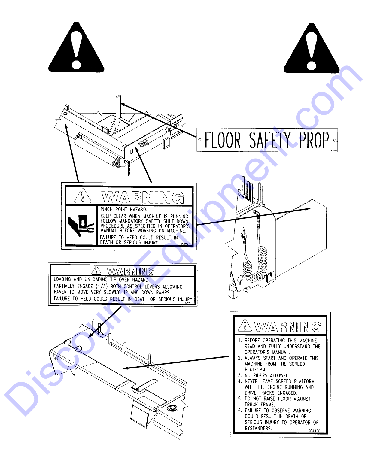
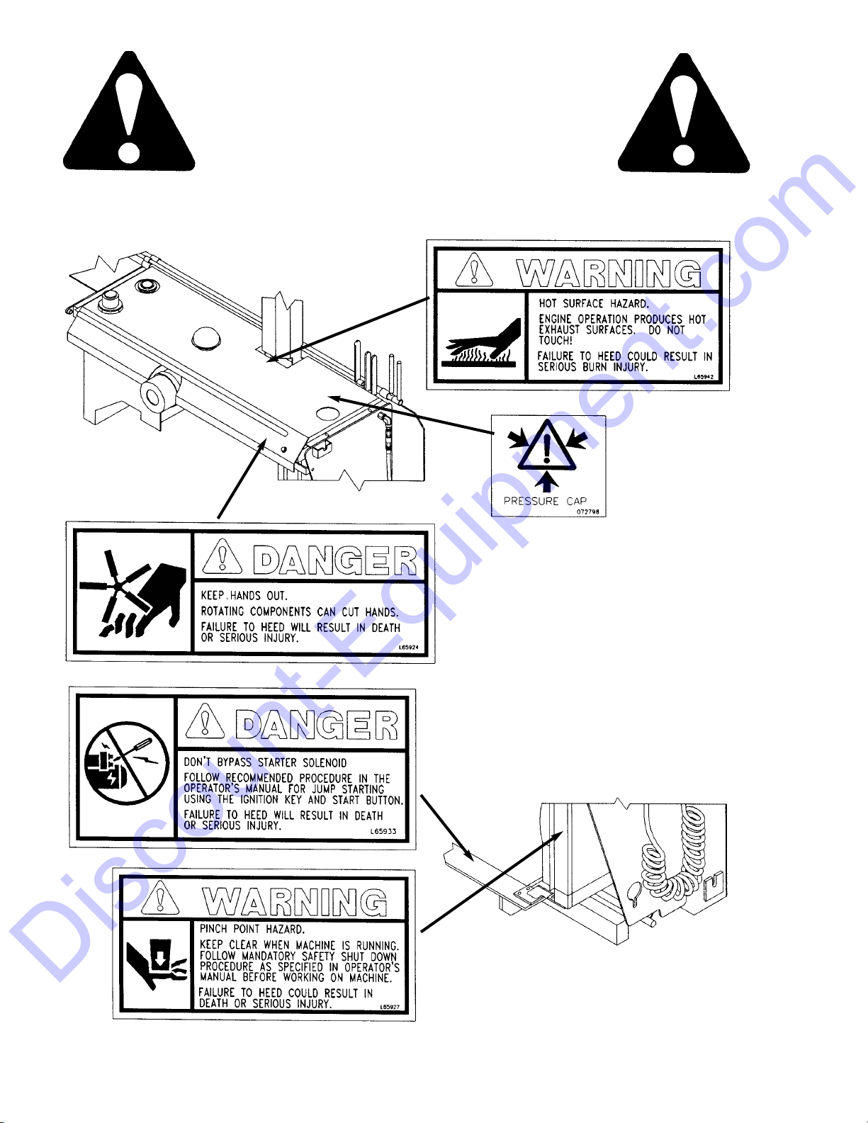
GUARDS AND SHIELDS
Whenever possible and without affecting Paver operation, Guards and Shields are used to protect potentially hazardous areas. In many places, Decals are also
provided to warn of potential dangers and/or to display
special operating procedures.
CONTROL INDICATORS & SWITCHES
(Figs. 1-5)
The Control Panel on the Backwall Console area contains the following Indicators and Switches:
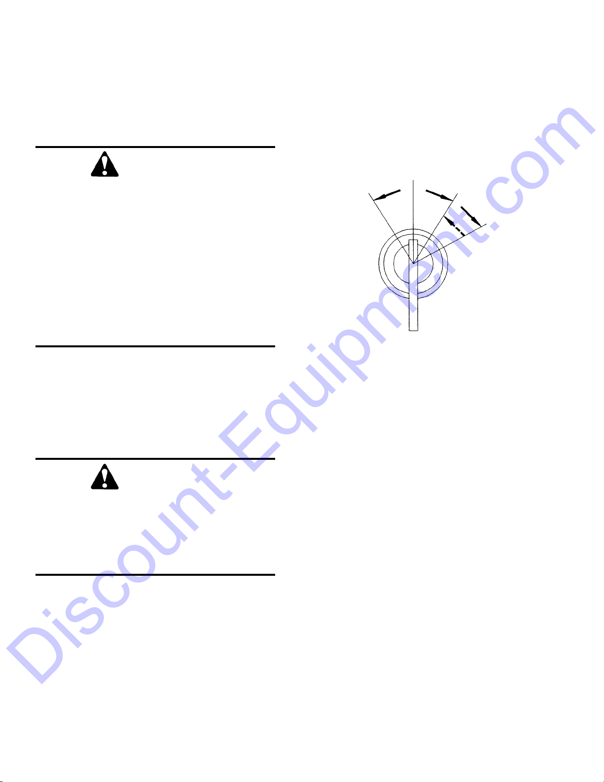
Starter Keyswitch
Off Position: When the Key is vertical in the Key
switch, power from the Battery is disconnected to the
Fig. 1
Control and Instrument Panel electrical circuits. Also,
this is the only position in which the Key can be inserted or removed from the Key switch.
RUN Position: When the Key is turned one position
clockwise from the vertical (OFF) position, power
from the Battery is supplied to all Control and
Instrument Panel electrical circuits.
Start Position: Turn the Keyswitch clockwise two
positions from the vertical (OFF) position to activate
the Engine Starter. The Keyswitch will return to the
RUN position automatically as soon as the Engine
Starts.
NOTE: The Key MUST always be returned to
the OFF position between starting attempts. The
Battery Charge and Engine Oil Pressure (Model
1649) Indicators should activate when the key is
turned to the RUN position.
Pre-Heat Glow Plug Indicator (1649): As an Engine
starting aid, pre-heating is required in a cold Engine
starting condition. This pre-heating uses Glow Plugs
which are activated by rotating the Keyswitch counterclockwise to the Pre-Heat position.
WARNING
Read and thoroughly understand ALL Safety
Decals on the Paver BEFORE attempting to
operate it. Do NOT attempt to operate the
machine unless ALL factory installed Guards
and Shields are properly secured in place.
CAUTION
Become familiar with and know how to use
ALL safety devices and controls on the Paver
BEFORE attempting to operate it. Know how
to stop the machine operation BEFORE
attempting to operate it. This GEHL Power
Box Paver is designed and intended to be
used ONLY with GEHL Company accessories
or a GEHL Company approved or referral
accessory. The GEHL Company can NOT be
responsible for operator safety if the Paver is
used with an unapproved accessory or attachment.
Chapter 5
CONTROLS, ATTACHMENTS
AND ACCESSORIES
PREHEAT
(1649 ONLY)
OFF
RUN
START
AUTO
RETURN
907389/AP297 16 Printed In U.S.A.
Discount-Equipment.com
Page 16
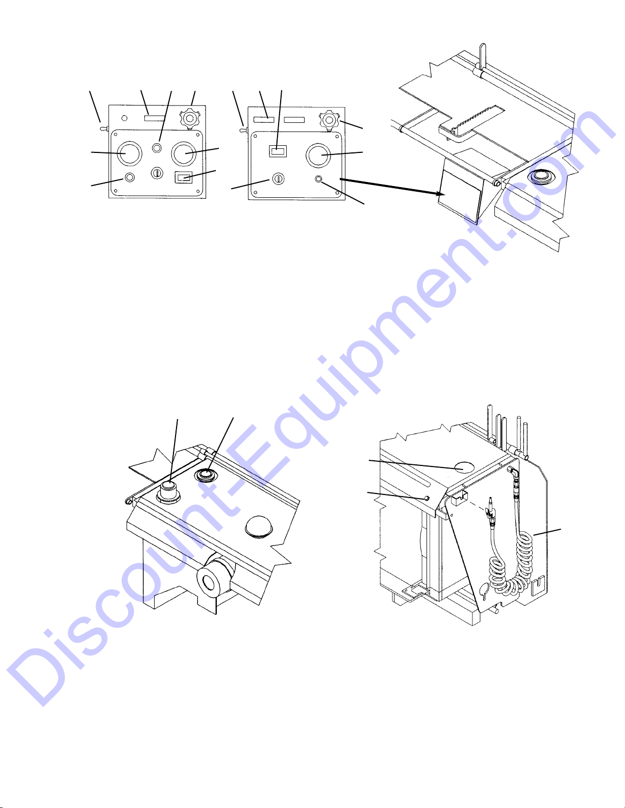
Fig. 3
1. Fuel Gauge 3. Radiator Fill (1649)
2. Fuel Fill Cap 4. Horn Push Button (Ea. Side)
5.
Spray Down Hose (Ea. Side)
Fig. 2
1.
Choke (1639) 4. Circuit Breaker (1639) 8. Engine Oil Pressure (1649)
2. Throttle 5. Keyswitch 9. Spray Down Pump Switch
3. Battery Gauge 6. Glow Plug Indicator (1649) 10. Hourmeter
7.
Water Temperature Gauge (1649)
11. Exhaust Diverter
1649 MODELS
1649 SHOWN
1649 SHOWN
1639 MODELS
TOP CONSOLE
2
3
4
3
10
5
7
6
21
3
4
5
9 11 8 2 9 1 10
Printed In U.S.A. 17 907389/AP297
Discount-Equipment.com
Page 17
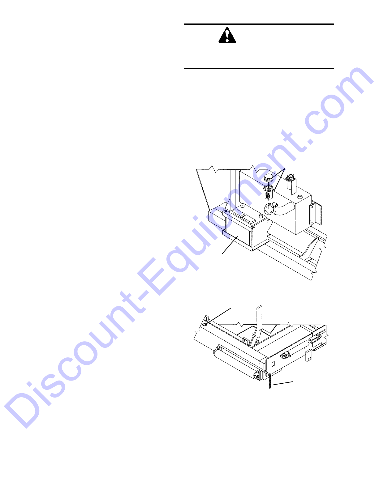
Fig. 4
1. Spray Tank Fill Cap
2. Battery
3.
Hydraulic Reservoir Fill Dipstick
4. Alignment Guide (Ea. Side)
Engine Throttle: This controls the Engine speed. Idle
position is with the Cable fully in. Operating position
is with the cable 1 to 1-1/2 inches out. Release the
Lock Ring, depress the red button on the Knob and pull
the Knob out to set speed. Rotate the Knob left or right
to fine adjust the speed during operation.
Horn Buttons: The Horn may be activated from a
Pushbutton on the left side or right side of the Console.
Fuel Level Gauge: Indicates the amount of fuel
remaining in the Fuel Reservoir.
Battery Charge gauge: Indicates the condition of the
charging system. During normal operation, this
Indicator should show minimum registeration.
Coolant Temperature Gauge: Indicates Engine
coolant temperature. Under normal operating condi-
tions, this Gauge should indicate approximately 185
o
F
(85
o
C).
Engine Oil Pressure (1649): This Lamp indicates
whether sufficient Engine lubricating oil pressure is
present or not. During normal operation, with the
Engine running, this Lamp should be OFF. During
starting and when the Engine is NOT running, this
Lamp will be ON
NOTE: If this lamp comes ON during normal
operation with the Engine running, STOP the
Engine immediately. After allowing the oil to drain
down for a few minutes, check the Engine oil
level. Maintain oil level at the FULL mark on the
dipstick
Circuit Breaker (1639): The 15 Amp Breaker protects
electrical circuits. If it is not in the “depressed position”, the Gauges and Indicators on the Control Panel
will not work and the Engine will shut off.
Hourmeter: Indicates the operating time of the
machine and should be used for keeping up the
Maintenance Log chapter of this manual.
Washdown Sprayer System: Sprayer is used periodically each day to wash down parts of the Paver which
contact asphalt. An asphalt releasing agent is used for
this.
Exhaust Diverter: Pull this Cable Handle OUT to
divert the Engine exhaust down through the Screed.
This heats up the Screed bottom surface when paving.
Push Handle IN to divert exhaust out through the
Muffler.
Fuel Level Gauge: The Gauge needle pointer indicates the amount of fuel remaining in the Reservoir.
CAUTION
Do NOT spray releasing agent on a HOT
Engine.
1
2
3
4
907389/AP297 18 Printed In U.S.A.
Discount-Equipment.com
Page 18
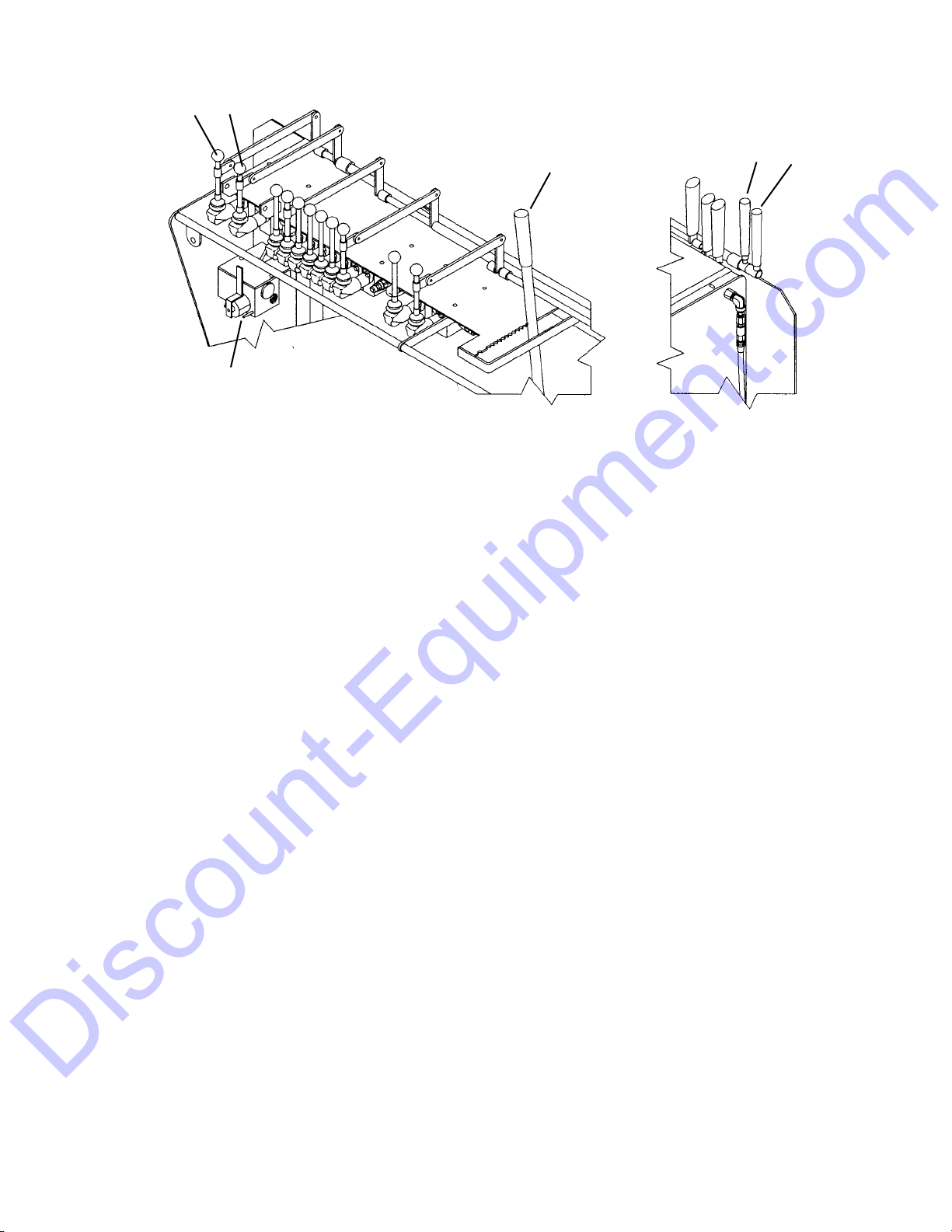
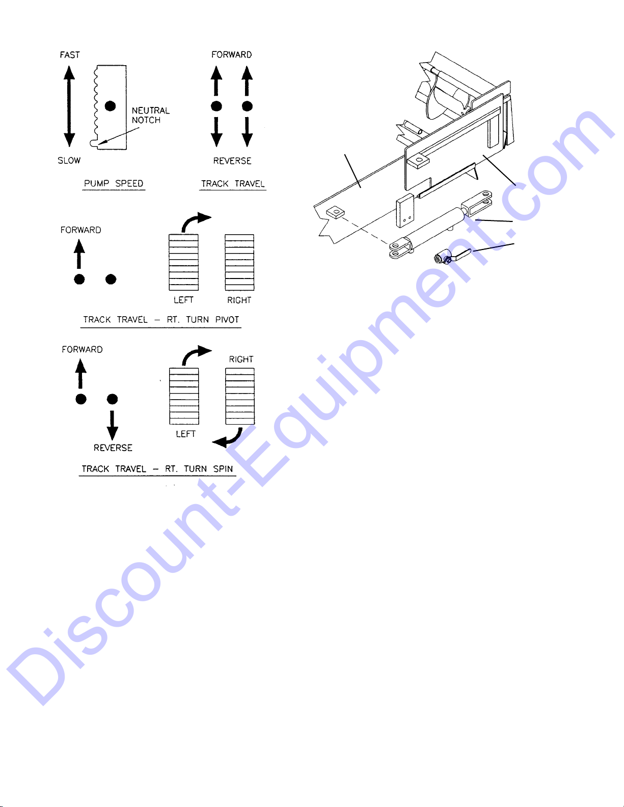
Fig. 5 - Travel Controls
1. Left Track Travel 3. Pump Speed
2.
Right Track Travel
4. Modular Steering
Hydraulic Fluid Reservoir: The Access/Fill Plug on
top may be removed to check fluid level..
NOTE: Before removing the Access/Fill Plug,
allow the fluid to cool for 10-15 minutes. Take a
wrench and slowly loosen the Hydraulic Breather
Cap on the Backwall Top Console to release system pressure.
Paving Alignment Guide: This is adjustable so the
Chain will align with a curb or the edge of a previously laid mat of asphalt..
TRAVEL CONTROLS (Figs. 5-6)
These controls are used to manuver the Paver around
on the jobsite or for road travel. Decals on the
Backwall Top Console area provide graphic representation of the various control actions.
Hydraulic Pump Variable Speed: This Lever
increases or decreases power to the Drive Motors. Push
the Lever FORWARD to increase speed, pull BACK to
decrease speed. Place the Lever in neutral when not
operating.
Track Travel: These two Levers control the Track
Drive Motors for forward and rearward movement and
also turning of the Paver. Both Levers are mechanically linked to Levers on the right side for control from
either side.
NOTE: “Right” and “left” are determined from a
position standing behind the unit and facing the
direction of forward travel. Pivot the machine at
slow speeds only.
Movement of the Travel Levers and the expected
results are as follows (See Fig. 6):
Move both Levers FORWARD to go forward. Move
both Levers REARWARD to go backwards. Move the
LEFT Track Lever FORWARD to pivot turn right.
Move the LEFT Track Lever REARWARD to pivot
turn left.
Move the RIGHT Track Lever FORWARD to pivot
turn LEFT. Move the RIGHT Track Lever REARWARD to pivot turn right.
Move both Levers in opposite directions to spin the
machine about its center position. Returning both
Levers to “neutral” position stops the Drive Tracks.
4
3
RT. SIDE CONTROL
1 2
1 2
Printed In U.S.A. 19 907389/AP297
Discount-Equipment.com
Page 19
Modular Steering: This control is used for dividing
the hydraulic oil to each Drive Motor. It will be necessary to adjust this valve as paving conditions vary.
With the Track Travel Levers both either forward or
rearword, set the Pump Speed Lever to “travel” or
“pave”. Position the Modular Control Lever LEFT to
move left and RIGHT to move right. Place the Lever
in the CENTER position to move straight ahead.
HOPPER CONTROLS (Figs. 7-8)
Hopper Floor: Move Lever BACK to raise Hopper.
Move Lever FORWARD to lower Hopper. This Lever
is mechanically linked to a dual control Lever on the
right side.
Right & Left Flow Gates: These control flow of
asphalt out of the Hopper. One Lever controls each
Gate. Move Lever BACK to open Gate. Move Lever
FORWARD to close Gate.
Side Gates: When paving only 9 ft. wide, the Side
Gates should be closed. This is achieved by closing the
Shut Off Gates with the Side Gate Valve ON, then turning the Side Gate Valve to the OFF position before reopening the Shut Off Gate.
Right & Left Feed Augers: These are used intermittently only with Extensions “out”. One Lever controls
each Auger. Move Lever BACK to turn on Auger.
Return Lever to “neutral” to turn off Auger. The right
Auger Lever is mechanically linked to a dual control
Lever on the right side.
SCREED PLATFORM CONTROLS
(Figs. 9-10)
Up & Down Position: Move the Lever BACK to
lower Screed so that it floats over asphalt feed forming
the finished mat surface. Move the Lever FORWARD
to raise Screed off mat.
Vibrator: This is used to agitate the mat of asphalt
passing under the Screed. Move the Lever BACK to
Fig. 6 - Track Travel Action
Fig. 7 - Side Gates (Left Side Shown)
1. Shut Off Valve
2.
Side Gate Cylinder
3. Side Gate
LOWER
FRAME
3
2
1
907389/AP297 20 Printed In U.S.A.
Discount-Equipment.com
Page 20
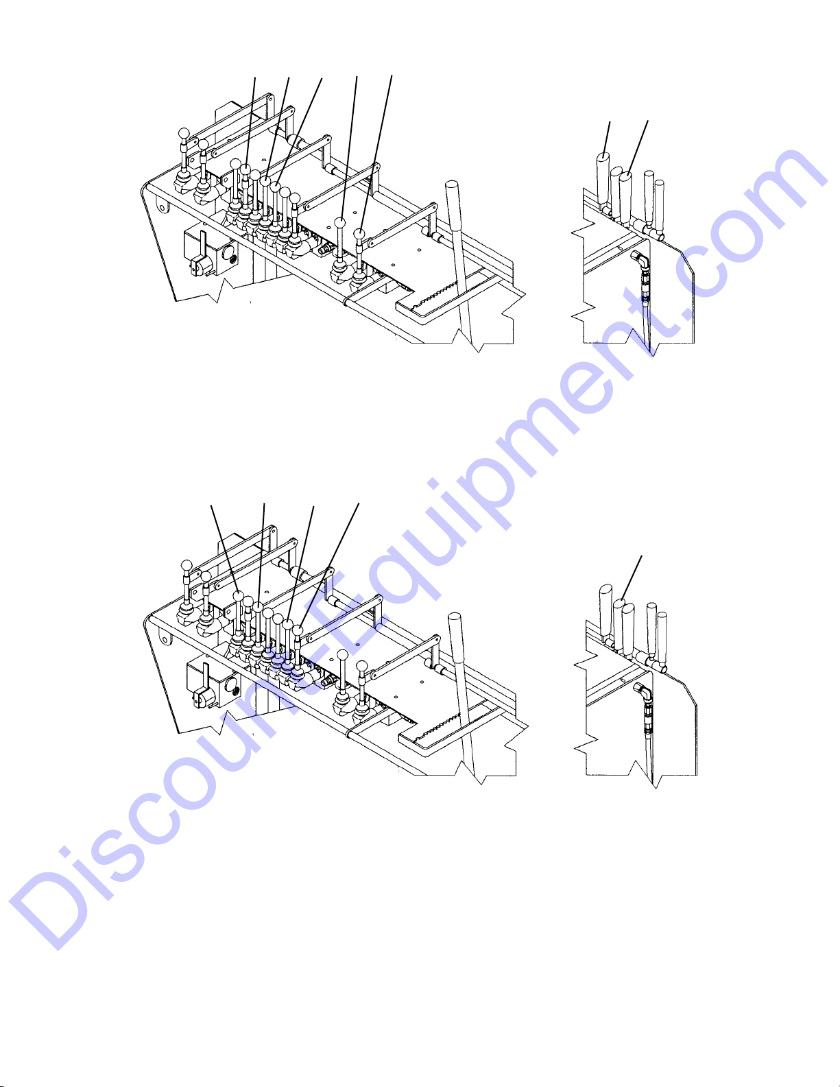
Fig. 8 - Hopper Controls On Backwall Console
1. Hopper Floor 4. Left Auger
2. Left Gate 5. Right Auger
3. Right Gate
Fig. 9 - Screed Controls On Backwall Console
1. Vibrator 3. Left Extension
2. Screed Lift 4. Right Extension
turn the Vibrator on. Allow the Lever to return to “neutral” to turn off the Vibrator.
Left & Right Extensions: These allow adjusting and
paving width beyond 9 feet. One Lever controls each
Extension. Move the Lever FORWARD to shift the
Extension inword. Move the lever BACK to shift the
Extension outward. The Right Extension Lever is
mechanically linked to Dual Control Levers on both
sides of the machine.
Depth Adjustment: The Screed has manually operated Adjustment Screws on each end that are used to set
the thickness of the asphalt mat. Turn the Screws
RT. SIDE CONTROL
51
1 2 3 4 5
RT. SIDE CONTROL
4
1234
Printed In U.S.A. 21 907389/AP297
Discount-Equipment.com
Page 21

Fig. 10 - Screed Adjustments On Screed (Right End Shown)
1.
Depth Adjust Screw
4. Side Extension
2.
Side Shoe Adjust 5. Side Shoe
3. Crown Turnbuckles 6. Depth Adjust Indicator
CLOCKWISE to increase the depth. Turn the Screws
COUNTER CLOCKWISE to decrease the depth. A
depth indicator on each end shows approximate adjustment setting in inches of mat thickness. These indicator numbers are only used as a reference. Actual mat
thickness must be measured with a Depth Gauge.
Crown Ajustment: This is made with two
Turnbuckles at the center of the Screed Platform.
Manually turn so screw ends push OUTWARD to
decrease the mat crown. Turn opposite so screw ends
feed INWARD to decrease the mat invert or valley.
Side Shoe Plate: Loosen Wing Nuts for adjustment
and re-tighten.
ACCESSORIES
NOTE:
All accessories are field installed unless
otherwise noted. Information and parts for field
installing of all of the accessories will be provided
by the Factory or GEHL Paver dealers.
Cut Off Plates & Baffles: The following choice of
Cut Off Plates & Baffles are available and must be
ordered separate by stock number from following list:
Description Stock Number
6” (152.4mm) for left side 806356
6” (152.4mm) for right side 806357
12” (304.8mm) for left side 806358
12” (304.8mm) for right side 806359
18” (457.2mm) for left side 806360
18” (457.2mm) for right side 806361
24” (609.6mm) for left side 806362
24” (609.6mm) for right side 806363
30” (762mm) for left side 806364
30” (762mm) for right side 806365
36” (914mm) for left side 805460
36” (914mm) for right side 805461
Bolt On Screed Extension: The following choice of
Extensions are available and must be ordered separate
by stock number below:
RACHET
HANDLE
3
16
45
2
907389/AP297 22 Printed In U.S.A.
Discount-Equipment.com
Page 22

Description Stock Number
6” (152.4mm) for left or right side 805464
12” (304.8mm)for left or right side 805466
18” (457.2mm)for left or right side 805468
Screed Propane Heat Kit: When desired or where
operating conditions require, this kit (without tank) is
optional with either 1639 or 1649 models. Order by
stock number 805462.
To operate the Propane Heater:
1. Check equipment carefully each time before
lighting.
2. Do NOT operate in enclosed areas or near flammable materials.
3. Close the Tank Valve and the valves on both
Handles.
4. Slowly open Tank Valve.
5. Adjust Regulator 15-20 psi.
6. Remove one burner from the Burner Tube
Support and light with a Striker. Place Burner
back into Burner Support Tube.
7. Light the second Burner in the same way.
8. Re-adjust the Regulator to 15-20 psi.
9. Do NOT leave Power Box Paver unattended
with burners on. If the flame is extinguished
quickly close valves. Wait 5 minutes before you
re-light burner to allow fumes to dissipate.
10. When Burners are not in use, close Valve on
Tank, crack and close Valves on Handles to
release gas pressure in Hoses.
Printed In U.S.A. 23 907389/AP297
Discount-Equipment.com
Page 23

GENERAL INFORMATION
ENGINE BREAK-IN
Your new Engine does NOT require extensive “breakin”. However, for the first 100 hours of operation, keep
the following in mind. Allow the Engine to idle for a
few minutes after every cold start. Do NOT idle the
Engine for long periods of time. Do NOT operate the
Engine at maximum power for long periods of time.
Check the oil level frequently and replenish, as necessary.
A special “break-in” oil is NOT used. The oil in the
Engine crankcase is the same specified for regular oil
changes. Change the oil and replace the oil filter at the
intervals specified in the Service chapter. Do NOT add
special additives or special “break-in” components to
the crankcase.
BEFORE STARTING ENGINE
Before starting the Engine and running the Paver, refer
to the Controls & Accessories Chapter and familiarize
yourself with the various operating controls, Indicators
and safety features.
STARTING THE ENGINE
BEFORE mounting the Screed Platform, walk completely around the machine to make sure NO one is, on,
or close to it. Let others near the area know you are
going to start up and wait until everyone is clear of the
machine.
Place all hydraulic function controls and the hydraulic
Pump speed control Lever in “neutral” position.
Chapter 6
OPERATION & ADJUSTMENTS
For 1639 Gas Models
1. Pull the Throttle control 1/4 to 1/2 open.
2. Pull Choke control to full “out” position (close
Choke Valve) for cold Engine starts. If re-starting
a warm Engine, little or no choking is required..
3. Turn the Key to START position. When Engine
starts, release the Keyswitch and it will automatically return to the RUN position.
4. Gradually return the Choke control to full “in”
position (open Choke Valve) as Engine warms up
and begins to operate smoothly.
For 1649 Diesel Models
1. Set the Throttle Control to 1/3 open.
2. Turn the Key to the START position. When the
Engine starts, release the Keyswitch and it will
automatically return to the RUN position.
3. In cold weather starting, first turn the Key counterclockwise to activate Glow Plug. When the
Indicator lamp comes on, proceed as in Step 2.
NOTE: Crank the Starter until the Engine is start-
ed. If the Engine fails to start within 15 seconds,
return the key to the “OFF” position, wait 2 minutes, and try to restart the Engine. Cranking the
Engine for longer than 15 seconds will result in
premature failure of the Starter.
After the above steps proceed as follows:
1. Allow a sufficient Engine warm-up time before
attempting to operate the Controls.
2. Check that Indicators are in normal condition.
3. Check the color of the exhaust gas. It should be
light blue or colorless.
4. Check that there are NO fuel, oil or Engine coolant
leaks, and NO abnormal noises or vibrations.
CAUTION
BEFORE starting the Engine and operating the
Paver, review and comply with ALL safety recommendations set forth in the SAFETY chapter of this manual. Know how to STOP the
Paver BEFORE starting it.
907389/AP297 24 Printed In U.S.A.
Discount-Equipment.com
Page 24

If the Battery becomes discharged and fails to have
sufficient power to start the Engine, jumper cables can
be used to obtain starting assistance. Refer to the Jump
Starting instructions in the Service chapter of this manual for safe jump-start procedure.
FIRST TIME OPERATION
Make sure the Engine is warm and then go through the
following procedures:
Familiarize yourself with various control levers. Raise
the Screed. Control the Paver travel forward and backward, then make left and right turns using the track
control levers and modular steering control. While
stopped, lower the Screed and activate the vibrator.
Divert the exhaust down to the Screed. Position the
Side Gates and Extensions in and out. Raise and lower
the Hopper and turn the Auger Motors on and off.
STOPPING THE PAVER
The following procedure is the recommended
sequence for stopping the machine:
1. Place both Track control Levers in “neutral”.
2. Lower the Hopper and Screed to full “down” positions.
3. Place all function control Levers in “neutral”.
4. Move the Throttle to “idle” position.
5. Turn the Keyswitch to “off” position. Always
remove the Key and take it with you for security
reasons.
GENERAL PAVER OPERATION
Walk Around Inspection
1. Inspect Suction Hose. Should be firm, not soft.
2. Check for hydraulic leaks.
3. Check Hopper Sides and Floor clearance.
4. Inspect the Screed.
5. Check the safety Guards and Covers.
Hands-On Check
1. Check the Fuel Gauge. Fill the Reservoir before
paving and as necessary.
2. Check the Engine Oil Level and replenish as necessary.
3. Check the cooling air intake on the Radiator
(1649) and the Engine cooling fins (1639).
4. Check the Air Cleaner for cleanliness and make
sure that components are tight to prevent intake of
unfiltered air.
5. Check the fuel Sediment Bowl (1639 Gas Engine)
for cleanliness. Check the Hourmeter against Fuel
Filter change schedule in the Maintenace Log of
this manual.
6. Check the Pump Speed Control Lever for full travel movement.
7. Clean external area of both Tracks (clean 3 to 4
times during working day).
8. Check for and remove as necessary, any asphalt
buildup in the Screed Platform exhaust ports
(located to the front and rear of each end).
CAUTION
Follow the manufacturer recommendations
regarding the use of proper fuel, lubricants
and oil.
To prevent a fire or explosion, allow the
Engine to cool down BEFORE attempting to
refill the Fuel Reservoir. A hot Engine could
ignite the fuel and burn you. Also, do NOT
smoke while refilling the Fuel Reservoir.
CAUTION
Clean external surface of Tracks with asphalt
releasing agent, using the Wash Down
Sprayer. Do NOT spray agent into Tracks
immediately before loading or unloading. Wet
Tracks can slip and lose traction.
CAUTION
Be SURE the area being used for test-running
is clear of spectators and obstructions. For
the first time operate the Paver with an empty
Hopper.
Printed In U.S.A. 25 907389/AP297
Discount-Equipment.com
Page 25

9. Check for and remove as necessary, any asphalt
buildup inside the Tracks.
10. Make a general inspection of the machine for loose
bolts and/or components.
11. Make sure safety Guards and Covers are in place.
If the Paver is found to be in need of repair or in any
way unsafe, or contributes to an unsafe condition, the
matter shall be reported immediately to the user’s designated authority. The machine shall NOT be operated
until it has been restored to a safe operating condition.
PAVING AT THE JOBSITE
The following areas should be “sprayed down” with
asphalt releasing agent (use the Spray Down Hose)
before paving and four times or more during the work
day. These areas should also be cleaned throughly after
each use of the machine:
Hopper, Augers and Screed (bottom).
Push Rollers.
Hydraulic Fluid Reservoir.
Asphalt Depth Adjustment Screws.
External Track and Sprockets.
Any part of the machine which contacts asphalt.
With the Engine warmed up, proceed as follows:
Positioning The Paver
1. Place Throttle in full “open” position and pull out
the Exhaust Diverter Handle. The exhaust will preheat the Screed in preparation to lay asphalt mate-
rial. When operating, the Throttle should
ALWAYS be at full RPM’s. The exhaust can be rediverted out through the Muffler periodically if
desired.
2. Maneuver the Paver into position for laying
asphalt with the Track Control Levers.
3. With Paver in position, move the Screed Control
Lever to “down” and hold until the Screed Lift
Cylinder is fully extended. This permits the Screed
to float free. Screed should be lowered onto a starting pad of asphalt or blocks of the desired paving
thickness.
4. Manually adjust the Screed Depth Control Screws
up or down, as required, to a neutral or free position. Slowly turn the Screws toward the “up” position until a slight amount of tension is felt. The
Screed is now set to lay asphalt to the approximate
thickness of the starting pad or blocks onto which
the Screed has been lowered.
5. Move the right and left Flow Gate Control Levers
to the the “closed” position and hold until both
Gates are fully closed. Set the Alignment guide on
each side of the lower front frame.
Filling The Hopper
6. Have the dump truck back up to the front of the
Paver until the truck tires are 1 to 2 inches from the
Push Rollers. Then move the Paver forward until
the Push Rollers contact the rear tires of the truck.
Do NOT raise the Screed.
7. Move the Hoper Control Lever to the “up” position
and hold until the Hopper almost touches the frame
or dump body of the truck.
8. Signal the truck driver to slowly raise the dump
body, allowing asphalt to flow from the truck into
the Hopper. Be prepared to lower the Hopper to
prevent the truck dump body from striking and
damaging the Hopper as the truck dump body is
raised. Fill the Hopper with asphalt.
9. Move the Flow Gate Control Levers to the “open”
position and hold until Flow Gates are completely
open. Asphalt will then gravity feed down to and
form a head of asphalt at the leading edge of the
Screed.
10. If the area to be paved is level and pushing the
truck is desired, place the Hydraulic Pump Speed
Control Lever forward approximately 1/3. The
CAUTION
NEVER operate the Paver with safety Guards
or Covers removed.
CAUTION
Do NOT spray Tracks before loading or
unloading as this could cause loss of traction.
907389/AP297 26 Printed In U.S.A.
Discount-Equipment.com
Page 26

Engine Throttle should be set at full power. Signal
the driver to leave the truck in neutral with thedump body raised a sufficient height to allow
asphalt to flow slowly but continuously inth the
Hopper.
Laying The Asphalt
11. Position the Extension Control Levers to adjust the
desired paving width if it is to be more than 9 feet.
12. Move the Track Control Levers to the “forward”
position. Continue forward, laying asphalt and
pushing the truck approximately 36 to 48 inches. If
vibration is desired on the Screed, move the
Vibrator Control Lever to “on” position at approximately the same time the Track Control Levers are
moved to the “forward” position.
13. Move the Track Control Levers to “neutral” position, stopping the Paver. ALWAYS move the
Vibrator Control Lever to “off” position when
stopping forward motion of the Paver. It may be
necessary to signal the truck driver to stop, if the
truck is moving.
NOTE: The truck should NOT be in gear nor
should the driver “ride” the brakes. Always advise
the truck driver of the procedure for pushing the
truck with the Paver.
14. Check thickness/depth of asphalt in the 36 to 48
inch mat and make necessaary adjustment using
the Manual Depth Adjustment Screws. Make
adjustments up or down gradually to avoid porpoising effect or ripples in the mat as a result of
adjusting too much in either direction. If the base
on which the asphalt is being laid is on grade and
level, only infrequent adjustments will be required
after initial asphalt thickness/depth setting is made.
NOTE: Refer to the Troubleshooting chapter in
this manual for Paver related, or material delivery
and compaction related paving mat application
problems.
15. Move the Track Control Levers to “forward” and
continue to pave until the truck is empty and the
Hopper is approximately 50% full.
NOTE: Leave a small head of asphalt at the
leading edge of the Screed while waiting for the
next load of asphalt. If the wait is longer than 10
to 15 minutes, pave 12 to 18 inches further and
again leave a small head of asphalt. Repeat in 10
to 15 minute intervals using asphalt remaining in
the Hopper until next load arrives.
If the Paver is to be used independently of the dump
truck, disregard procedures involving pushing the
dump truck for continuous feed while paving (discussed in Steps 10-13) and refer to the following:
16. After the Hopper is fully loaded, signal the truck
driver to lower the dump body, stopping the flow
of asphalt to the Paver. Simultaneously, the Paver
Operator should move the Hopper Control Lever
to the “up” position raising the Hopper to avoid
asphalt spills from the front of the Hopper.
17. The Paver Operator should then signal the truck
driver to move forward to the next place to reload
the Paver. This next reloading place may be directly in front of the Paver at a point where the Paver
Operator expects the Hopper to be emptied, or
another location on the jobsite.
PRECAUTIONS WHILE PAVING
The right side Control Levers for Auger, Extension,
Track and Hopper modes allow a two-man operation to
avoid making “blind” joints and to reduce cycle time
when paving in two directions.
The Screed Vibrator should be operated ONLY when
the Paver is moving to avoid undue compaction in the
mat when the Paver is stopped.
Do NOT raise the Hopper against the truck frame or
the dump body of the truck.
When pushing a truck on level ground, the truck
should NOT be in gear and the truck brakes should
NOT be held. The Paver will NOT push a truck with
the brakes on.
The two independently operated Augers need ONLY
be used when the Extensions are out and then only “off
and on”. The Augers are used ONLY for keeping the
extended area fully charged with asphalt.
NOTE: Do NOT leave the Augers operating con-
tiuously unless required!
If the Hopper is loaded and the Operator wishes to
close the Flow Gates to transport material to an area
inaccessible to the truck, or reposition the Paver for the
next pass, etc., the following procedure should be
employed. ALWAYS lower the Hopper as low as pos-
Printed In U.S.A. 27 907389/AP297
Discount-Equipment.com
Page 27

sible without spilling asphalt. Close one Flow Gate and
then the other. Lowering the Hopper substantially
decreases the weight being lifted by each Flow Gate.
Make sure Screed Extensions are also closed.
Do NOT pull Paver with another vehicle except in an
emergency situation (loss of hydraulic power or
Engine failure). The Track Control Levers MUST be
locked in the “float” position. Remove the Lock Lever
and place control levers all the way forward. Replace
the Lock Lever. Do NOT pull the Paver backwards! Do
NOT pull the Paver at high speeds
When paving uphill, lower the Hopper as needed, placing more weight directly over the Tracks to increase
traction.
Handling Asphalt Spills
NOTE:
ALWAYS remove asphalt spill (large or
small) from the path of the Paver Tracks to prevent loose asphalt from getting in the Tracks , or
building up on the Sprockets.
The following procedure should be used if the asphalt
truck drives away from the Paver when loading or
pushing the truck, resulting in a large asphalt spill in
front of the Paver:
1. Stop the Paver.
2. Lower the Hopper as low as possible without
spilling more asphalt.
3. Close one Flow Gate and then the other.
4. Windrow spilled asphalt material to the center and
in front of the Paver, making sure the asphalt is
removed from the path of the Paver Tracks.
5. Move the Track Control Levers to “forward”, con-
tinuing to pave with asphalt previously gravity fed
from the Hopper. As the asphalt head from the
Hopper begins to run thin, the windrow asphalt
should be at the leading edge of the Screed. If this
is the case, continue to pave using the windrow
CAUTION
Do NOT attempt to move HOT asphalt mix with
your hands or feet. Contact can cause serious
skin burns!
asphalt, opening both Flow Gates as the windrow
asphalt begins to run thin.
If this is not the case, open both Flow Gates
approximately 1/3, maintaining a full head of
asphalt at the leading edge of the Screed until the
leading edge strikes the windrow asphalt. Continue
to pave.
NOTE: Failure to follow this procedure, in the
event of asphalt spills, will result in asphalt
buildup and eventual damage to the Flow Gate
Cylinders and the Tracks.
HIGHWAY TRAVEL
For short distance highway travel, attach a SMV (Slow
Moving Vehicle) Emblem, purchased locally, to the
back of the Paver
NOTE: ALWAYS follow ALL state and local reg-
ulations regarding the operation of equipment on
or across public highways! Also, whenever any
appreciable distance exists between jobsites or if
operation on public highway is prohibited, BE
SURE to transport the Paver using a vehicle of
appropriate size and weight.
TRANSPORTING BETWEEN
JOBSITES (Figs. 11-13)
When transporting the Paver, know the overall height
to allow clearance of obstructions. Remove or tape
over the slow moving vehicle emblem (SMV) if it will
be visible to traffic.
Tie-down slots are provided on the front of the
hydraulic reservoir portion of the frame and the lower
rear sides of the backwall. Chains can be inserted
through these brackets and slots to secure the Paver
while transporting.
CAUTION
ALWAYS abide by the following recommended
procedures and guidelines, when attempting
to use ramps to load the Paver onto (or unload
it from) a truck or trailer. Failure to heed can
result in damage to equipment and a serious
personal injury or death!
907389/AP297 28 Printed In U.S.A.
Discount-Equipment.com
Page 28

NOTE: A matched pair of ramps is required.
1. (Fig. 11) The ramps MUST be of sufficient
strength to support the machine. Whenever possible, the use of strong wood covered steel ramps is
recommended as well as some type of center supporting block.
2. The ramps MUST be firmly attached to the truck
or trailer bed with NO step between the bed and
the ramps.
3. Incline of ramps MUST be less than 15 degrees
(ramp length MUST be at least 16 feet long).
4. Ramp width MUST be at least 1-1/2 times the
Track width.
5. Block the front and rear of the tires on the truck or
trailer (if so equipped, engage the parking brake).
Unloading With Ramps
1. (Fig. 12) Remove chain binder from tiedown
points on the front of the Paver.
2. Start the Engine according to starting procedure in
this manual.
3. With Pump Speed Control Lever in “slow” position and Throttle open about 1/4, place the Track
Control Levers in “reverse”. The Paver will move
backwards, releasing tension from the two tiedown
chains on the rear of the Paver.
4. (Fig. 12) Remove the chains from both tiedown
points on the rear of the Paver.
5. Move the Screed Control Lever to “up” position
and hold until Screed is raised completely.
6. (Fig. 13) To avoid bumping the rear edge of the
Screed on the bottom of the ramps, turn the Depth
Adjustment Screws 7 or 8 turns counterclockwise.
This raises the rear edge of the Screed approximately 1 inch.
7. Using the Track Control Levers, align the Paver
Tracks with the ramps. When unloading from the
rear, rotate and align the Paver Tracks. To rotate
place one Track Control Lever in “forward” and
the other Lever in “reverse”.
8. Move the Paver forward to the ramps and stop the
Paver by placing both Track Control Levers in
“neutral” position.
CAUTION
ALWAYS place the Pump Speed Control Lever
in “slow” position when operating the Paver
on the truck bed. ALWAYS unload the Paver in
“forward”.
Do NOT walk beside, behind or in front of the
Paver during unloading procedures.
Fig. 11
Fig. 12
1. Rear Tiedown Points (Ea. Side)
2. Front Tiedown Points
1
2
Printed In U.S.A. 29 907389/AP297
Discount-Equipment.com
Page 29

9. Move the Pump Speed Control Lever to “slow”
position. This will prevent the machine from “freewheeling” down the ramps.
10. The Throttle should be set at 1/2 minmum to full
open.
11. Clear the area at the bottom of the ramps of all personnel and other obstructions.
12. Simultaneously place both Track Control Levers in
“forward” position, allowing the Paver to travel to
the ground.
NOTE:The operator should ride on the Paver
with one hand on both Track Control Levers at all
times, to maintain positive control of the Paver.
Emergency stops are accomplished by placing
both Track Control Levers in “neutral” position
Loading With ramps
1. Move the Paver to a position that aligns with the
ramps so the Paver will be in position to load in
reverse. Stop the Paver.
2. Move the Pump Speed Control Lever at 1/3 to 1/2
speed.
3. Place the Throttle Control at full open position.
4. Raise the Screed to the “full up” position with the
Screed Control Lever.
5. (Fig. 13) To avoid bumping the rear edge of the
Screed on the ramps, turn the Depth Adjustment
Screws counterclockwise (7 or 8 turns).
6. Fully engage both Track Control Levers rearward,
allowing the Paver to move slowly up the ramps.
The operator should ride on the Paver with a hand
on both Track Control Levers at all times to stop
the Paver if travel is not straight.
7. Immediately after the Paver is on the vehicle flat
bed, STOP the Paver.
8. Move the Pump Speed Control Lever to “slow”
position and reduce the Throttle to “idle” position.
CAUTION
NEVER attempt to adjust travel direction (even
slightly) while traveling on the ramps. Instead,
back up and onto the truck bed, off of the
ramps, and re-align the Paver with the ramps.
Fig. 13
CAUTION
NEVER attempt to adjust travel direction (even
slightly) while traveling on the ramps. Instead,
back up and onto the truck bed, off of the
ramps, and re-align the Paver with the ramps.
Do NOT walk beside, behind or in front of the
Paver during loading procedures.
ALWAYS place the Pump Speed Control Lever
in “slow” position when operating the Paver
on the truck bed. ALWAYS load the Paver in
“reverse”.
Check for and remove oil, grease, fuel or other
substance on the ramps that may cause the
Tracks to lose traction or slip.
Do NOT wash down the Paver with asphalt
releasing agent just before loading on the
vehicle. The Paver Track may become wet and
may slip on the ramps.
ADJUSTMENT
SCREW
1-IN.
907389/AP297 30 Printed In U.S.A.
Discount-Equipment.com
Page 30

9. Using the Track Control Levers, maneuver the
Paver on the trailer or truck for best transporting
and balanced position.
10. Rear Loading: After the Paver is on the vehicle
bed, place one Track Lever in “forward” and one in
“reverse”. The machine will rotate to legal width
for transport.
11. Return the Screed to flat position by turning the
Depth Adjustment Screws in a clockwise didrection (7 or 8 turns).
12. (Fig. 12) Lower the Screed and place chains in the
two tiedown points at the rear of the Paver. Drive
the paver forward allowing chains to tighten slightly.
13. (Fig. 12) Place a tiedown chain in the tiedown
point on the front of the Paver and bind down to
the vehicle bed.
14. Turn the Keyswitch to “off” position and remove
the Key.
In Transit
If in transit for a few days: (a) Disconnect the Battery.
(b) Clean all bright surfaces and coat with heavy, very
high flash point grease to prevent rusting.
THEFT DETERRENTS
THE CERTAINTY OF APPREHENSION IS A
STRONG DETERRENT TO THIEVERY OF CONSTRUCTION EQUIPMENT! GEHL has recorded
Part Numbers and Serial Numbers. Users should take
as many of the following actions as possible to discourage theft, to aid in the recovery in the event that
the machine is stolen, or to reduce vandalism:
1. Remove keys from unattended machines.
2. Attach, secure, and lock all anti.vandalism and
anti-theft devices on the machine.
3. Inspect the gates and fences of the vehicle storage
yard. If possible, keep machines in well lighted
areas. Ask the law enforcement agency having
jurisdiction to make frequent checks around the
storage or work sites, especially at night, during
weekends, or on holidays.
4. Report the theft to the dealer and insurance company. Provide the model, and all serial numbers.
5. Request that your dealer forward this same information to GEHL Co.
Printed In U.S.A. 31 907389/AP297
Discount-Equipment.com
Page 31

GENERAL INFORMATION
NOTE:
The Maintenance Log chapter in this
manual has provisions for recording the dates and
Hourmeter readings after lubrication or other service has been performed; use those spaces to
keep a log for maintaining a current service interval record. Proper routine lubrication is an important factor in preventing excessive part wear and
early failure.
LUBRICANTS
The following chart lists the locations, temperature
ranges and types of recommended lubricants to be used
when servicing this machine. Also refer to the separate
Engine Manual (provided) for additional information
regarding recommended Engine lubricants, quantities
required and grades.
NOTE: Refer to Operator Services topic in
Service Chapter of this manual for detailed information regarding periodical checking and replenishing of lubricants.
GREASING & LUBRICATION
Refer to the following pages for locations and greasing
frequencies. Wipe dirt from the grease fittings before
greasing them to prevent contamination. Replace any
missing or damaged fittings. To minimize dirt buildup, avoid excessive greasing.
Chapter 7
LUBRICATION
CAUTION
NEVER attempt to lubricate or service this unit
when any part of the machine is in motion.
ALWAYS BE SURE to exercise the MANDATORY SAFETY SHUTDOWN PROCEDURE
(page 10) BEFORE proceeding to lubricate or
service this equipment.
Hydraulic System Reservoir
Use SUNVIS 846, or equivalent
which contains anti-rust, anti-foam and anti-
oxidation additives & conforms to ISO VG46.
Capacity:
20 Gallons (75.7 liters)
All Grease Fittings
Use No. 2 Lithium-based Grease
Engine Crankcase Oil
Ambient Temperature Grade*
Below 32oF (0C) SAE 10 or 10W-30
32-77oF (0-25C) SAE 30 or 10W-30
Above 77oF (25C) SAE 40 or 20W-40
*Service Classification: API - CD/CE/CF-4
Capacity
4 Quarts (3.8 liters) - Gas Engine
6.9 Quarts (6.5 liters) - Diesel Engine
Torque Hubs Gear Oil
Use API-GL-5 80w90
Capacity (each Hub):
17 ounces (481 grams)
Printed In U.S.A. 33 907389/AP297
NOTE: Always dispose of waste lubricating oils,
anti-freeze and hydraulic fluids according to local
regulations or take them to a recycling center for
disposal. Do NOT pour them onto the ground or
into a drain.
Discount-Equipment.com
Page 32

LUBRICATION LOCATIONS
NOTE: See the the Service chapter of this
Manual for further details.
Every 10 Hours (or daily)
1. Check Engine Oil Level.
2. Grease Depth Adjustment Screws (2 ea.).
Every 40 Hours (or weekly)
3. Grease Track Adjuster Yoke (1 per Track).
4. Check Hydraulic Fluid Level.
Every 100 Hours
5. Change Hydraulic Filters. (2 ea.).
Every 250 Hours
6. Check Track Torque Hub Fluid Level (2 ea.).
7. Change Engine Oil.
Every 500 Hours
8. Grease Pump Speed Control Linkage (2 ea.).
9. Change Engine Oil Filter.
Every 2000 Hours
10. Change Hydraulic Reservoir Fluid.
11. Clean or Replace Hydraulic Sump Strainer.
Replacement Filters Chart
1649 Diesel Engine
Oil Filter Element Gehl P/N P700122
Fuel Filter Element Gehl P/N 123828
1639 Gas Engine
Oil Filter Element Gehl P/N P221050
In-Line Fuel Filter Gehl P/N P217000
Hydraulic System Filters
Screw-On Filter Element Gehl P/N 074830
Reservoir Sump Strainer Gehl P/N 128299
Air Cleaner
Dry Element (Diesel Eng.) Gehl P/N 055017
Dry Element (Gas Eng.) Gehl P/N P700504
Pump Control Lube Details
6
907389/AP297 34 Printed In U.S.A.
Discount-Equipment.com
Page 33

BASIC MACHINE LUBRICATION CHART
Engine Oil
Gear Oil
Hydraulic Oil Grease
2000 HOURS
500 HOURS
250 HOURS
40-100 HOURS
10 HOURS
1
9
8
2
2
7
5
10
11
4
63
Printed In U.S.A. 35 907389/AP297
Discount-Equipment.com
Page 34

Chapter 8
TROUBLESHOOTING
CAUTION
Do NOT attempt to service or repair major
components, unless authorized to do so by
your GEHL Dealer. Any Unauthorized Repair
will Void the Warranty.
The following Troubleshooting Guide lists potential
problems, as well as possible causes and remedies, for
the Gehl Paver.
When a problem occurs, don’t overlook simple causes.
A malfunction could be caused by something as simple
as an empty Fuel tank. After a mechanical failure has
been corrected, be sure to locate the cause of the problem.
PROBLEM POSSIBLE CAUSE REMEDY
Engine operation erratic. Refer to Engine troubleshooting. Refer to Engine troubleshooting.
Paver difficult to steer. One forward/reverse lever not fully
engaged. Engage lever.
NOTE: Normal lead off to
one side may be as much Linkage for dual controls binding. Free up linkage.
as 1 to 2 ft. in 100 ft. of
travel under little or no Tracks not properly aligned. Correct alignment.
load conditions
Soft or uneven terrain may Internal leakage in Modular Replace seals.
cause lead off which may Steer Valve.
be interpreted as steering
problems. Actual operating
conditions will cause the
lead off to change.
Paver slowing down or Engine not running at rated speed. Disassemble Drive Valve and
excessive power loss. clean Load Checks.
Check Fuel Filter.
NOTE: Travel speed Failure of hydraulic system component Refer to hydraulic component(s)
(0-130 FPM) (Filter, Motor, Pump, etc.) troubleshooting.
Hydraulic controls stall to Hydraulic system leaks. Locate leaks and correct.
freely or won’t operate
under a load. Repair faulty component.
Refer to hydraulic components
troubleshooting
GENERAL PAVER PROBLEMS DURING OPERATION
907389/AP297 36 Printed In U.S.A.
Discount-Equipment.com
Page 35

PROBLEM POSSIBLE CAUSE REMEDY
Screed not hot enough. Engine not running at high enough RPM. Refer to Engine troubleshooting.
Excessive exhaust leakage. Check for and correct leaks.
Exhaust ports at end of Screed plugged. Clear ports.
Outside air too cold/or windy. Use optional propane heater.
GENERAL PAVER PROBLEMS DURING OPERATION (Cont.)
PROBLEM POSSIBLE CAUSE REMEDY
Wavy Surface (ripples). 1. Fluctuating head of materials. 1. Maintain full head of material.
2. Finisher speed too fast. 2. Reduce speed with the fast-slow
lever.
3. Excessive play in Screed 3. Replace attaching bolts.
mechanical connection.
4. Screed riding on Lift Cylinder. Lower Cylinder completely.
Wavy surface See Causes “1, 3, 4”.
(long waves)
5. Overcorrecting Thickness Control Make more moderate corrections as
Screws. infrequently as possible.
6. Running hopper empty between Stop Paver before head of material
loads. reaches Screed area.
7. Sitting long period between loads. Empty Hopper completely if waiting
period lets asphalt cool.
Tearing of mat See Cause “2”.
(full width)
8. Screed plates worn or warped. Replace Wear Plate.
9. Cold Screed a) Check exhaust ports in Screed.
b) Check for exhaust leaks.
Tearing of mat See Causes “8, 9”.
(center streak)
10. Too little crown in Screed. Increase lead crown.
Tearing of mat See Causes “8, 9”.
(outside streak)
11. Too much lead crown in Screed. Decrease lead crown.
12. Screed extensions installed Raise Extension Strike Offs.
incorrectly.
PAVER RELATED MAT PROBLEMS
Printed In U.S.A. 37 907389/AP297
Discount-Equipment.com
Page 36

PROBLEM POSSIBLE CAUSE REMEDY
Mat texture not uniform See Causes “1, 2, 4, 7-9, 12”
Screed marks See Cause “3”.
Screed not responding See Causes “2-4”.
to correction.
Poor pre-compaction. See Cause “2”.
13. Screed riding on Lift Cylinder. Lower Cylinder completely.
Poor longitudinal joint. 14. Improper joint overlap. Overlap 2” maximum.
Poor transverse joint. See Causes “3, 13”
15. Incorrect nulling of Screed. Increase “pitch” of Screed before
starting.
PAVER RELATED MAT PROBLEMS (Cont.)
PROBLEM POSSIBLE CAUSE REMEDY
Wavy surface 1. Improper base preparation. Review base installation.
(short waves - ripples)
2. Improper rolling operation. Decrease speed.
3. Improper mix design (aggregate). See Asphalt Paving Manual.
4. Improper mix design (asphalt) See Asphalt Paving Manual.
5. Mix segregation. Asphalt plant mixing too long.
6. Variation of mix temperature. Asphalt plant burners not heating
consistantly.
Wavy surface See Causes “1, 5, 6”
(long waves)
7. Trucks bumping finisher. Stop truck short of Paver and drive
Paver to truck.
8. Truck holding brakes. Driver must apply only enough so that
truck stays “in Paver”.
9. Reversing or turning too fast Cycle must be slow but deliberate.
of rollers
10. Parking roller on hot mat. Move to cooler surface before parking.
Park at 45
o
angle.
MATERIAL-DELIVERY-COMPACTION RELATED MAT PROBLEMS
907389/AP297 38 Printed In U.S.A.
Discount-Equipment.com
Page 37

PROBLEM POSSIBLE CAUSE REMEDY
Tearing of mat See Causes “3-7”.
(full width)
11. Improper mat thickness. Mat thickness must be twice size of.
the largest aggregate.
12. Cold mix temperature.. Check with asphalt plant for hotter
asphalt mix.
Mat texture See Cause “12.
(center or outside streaks)
Mat texture See Causes “1, 3-6, 11, 12”.
(non uniform)
Screed marks See Causes “7, 8”.
Screed not responding See Causes “6, 11, 12”.
to correction
Auger shadows See Causes “3-5”.
Poor pre-compaction See Causes “1, 11, 12”.
Poor longitudinal or See Causes “2, 12”.
transverse joint.
Transvers cracking See Causes “1-4, 6, 13”.
(checking).
Mat shoving under See Causes “1-4, 6, 9, 13”.
Roller.
Bleeding or fat spots See Cause “3, 4, 6, 13”.
in mat.
Roller marks. See Causes “1, 2, 6, 9, 10”.
Poor mix compaction. See Causes “1-4, 6, 9, 10, 12, 13”.
MATERIAL-DELIVERY-COMPACTION RELATED MAT PROBLEMS (Cont.)
Printed In U.S.A. 39 907389/AP297
Discount-Equipment.com
Page 38

PROBLEM POSSIBLE CAUSE REMEDY
Incapable of maintaining. Internal oil leak at the spool. Replace entire valve housing & spool.
the load.
Oil leaking at relief valve port. Disassemble and clean or replace
relief valve.
Load check poppet or seat damaged Replace poppet and seat assembly.
(located inside sections).
Spool sticking or does Hydraulic oil contaminated. Drain and replace with fresh oil. Also
NOT move. replace Filters.
Valve clogged with dirt. Remove dirt and clean assembly.
Inside of plunger cap filled with oil. Replace seal on end of cap.
Foreign matter at spool internal stop. Remove foreign matter or replace
entire valve section & spool assembly.
Pressure too high Using pressure gauge, readjust pressure.
Lever or link bent. Remove and replace.
Spool bent. Replace entire valve assembly.
Return spring failing. Replace spring.
Return spring or cap misaligned. Loosen, realign and retighten.
System oil temperature distribution Allow sufficient warm-up for
NOT uniform. entire system.
Oil leaking at seals. Paint sticking at seal. Remove and clean the seal.
Back-pressure in valve. Replace hydraulic Oil Filter.
Dirt in seal. Remove and clean the seal.
Seal plate has loosened. Replace valve housing as assembly.
Seal broken or damaged. Remove and replace seal.
Controls feel heavy. Foreign matter in control valve spool. Clean control valve.
Valve spool sticking. Replace entire valve housing.
Control linkage lacking lubrication. Properly lubricate.
DRIVE AND MAIN CONTROL VALVES
907389/AP297 40 Printed In U.S.A.
Discount-Equipment.com
Page 39

PROBLEM POSSIBLE CAUSE REMEDY
System will not operate 1. Oil supply low. Check oil level and fill.
in either direction
2. Oil Filters clogged. Replace Filter Element.
3. Oil too heavy. Use proper viscosity oil.
4. Control linkage misadjusted. Check to see if control linkage is
binding or unfastened
5. Low charge pressure See remedy for Causes “6-9”.
Pressure should be 300-350,
100 PSI minimum.
6. Gear pump input shaft damaged. Inspect gear pump input shaft for
damage.
7. Auxiliary pump charge relief valve Replace or adjust relief valve.
damaged.
8. Gear pump gears worn or scored. Replace defective parts.
9. Gear pump damaged. Disassemble, inspect for damage.
10. Relief valve stuck open. Remove, clean or replace.
11. Damaged check valve. Dissassemble and check if valve is
faulty or damaged.
System noisy. 12. Air in system. Low oil level in Reservoir.
13. Loose suction line. Tighten fittings or lose hose.
14. Clogged Suction Filter. Replace Element.
15. Internal Pump or Motor damage. Dissassemble, inspect, repair or replace.
Sluggish response to See Cause “12”. Also see remedy for Causes “1-3, 13”.
acceleration or
decceleration. See Cause “15”.
16. Low charge pressure. See remedy for Causes “6, 7, 9”.
17. Relief Valve dirty or damaged. Remove, clean or replace.
Oil leaking from Pump 18. Defective seal. Replace seal and/or complete
or Motor. assembly.
HYDRAULIC PUMP AND MOTORS SYSTEM
Printed In U.S.A. 41 907389/AP297
Discount-Equipment.com
Page 40

PROBLEM POSSIBLE CAUSE REMEDY
Insufficient hydraulic Relief Valve pressure setting Readjust Valve pressure setting.
Cylinder power decreased.
Cylinder internal oil leakage Replace seals.
Cylinder piston or seals defective. Replace piston or seals.
Control Valve internal oil leakage. Replace entire Valve housing.
Hydraulic Cylinder Cylinder seals defective. Replace seals.
external oil leakage
Cylinder rod damaged. Replace rod.
Piston does NOT Oil temperature is abnormally high. Lower the oil temperature.
move smoothly.
Air being taken into system. Replenish oil and retighten
suction connections.
Seals defective Replace seals.
HYDRAULIC CYLINDERS
PROBLEM POSSIBLE CAUSE REMEDY
Starter will NOT turn. Keyswitch is in OFF or RUN position. Turn Keyswitch to START position.
Speed control not in OFF position. Move speed control to OFF position.
Faulty wiring and/or terminations, or Troubleshoot circuit and repair.
Fuse open.
Faulty Starter switch Replace.
Battery NOT adequately charged. Recharge.
Battery discharges and/ Terminal or cables are loose or Clean terminals and cables and
or will NOT recharge. corroded, Battery is defective, and/or retighten or replace Battery; have
Alternator (or Regulator) defective. dealer check Alternator
(or regulator).
Battery electrolyte level low. Replenish with distilled water.
Alternator defective. Replace or repair.
Operating Horn, etc. Fuse blown. Check cause ,correct and/or replace
does NOT function. Fuse
Charge Indicator Faulty Alternator Replace.
does NOT activate
before Engine starts. Battery is NOT sufficiently charged. Recharge.
ELECTRICAL SYSTEM
907389/AP297 42 Printed In U.S.A.
Discount-Equipment.com
Page 41

PROBLEM POSSIBLE CAUSE REMEDY
Engine will NOT turn Starter motor defective or Replace motor and/or repair
over. faulty wiring connections. wiring connections.
Starter motor has Battery is run down, Starter is Charge Battery, repair/replace
insufficient power to defective and/or wiring connections Starter, and/or tighten connections.
turn Engine over. are broken or loose.
Engine cranks-over Fuel Reservoir is empty. Replenish fuel supply.
but will NOT start.
Engine crankcase oil is too heavy. Drain and replace crankcase oil
with proper viscosity oil.
Engine is cold. See OEM Engine Manual.
Engine cuts-out Out of fuel Replenish fuel.
abruptly.
Fuel Filter is clogged and/or air is Clean or replace Fuel Filter and/or
trapped in the fuel system. de-aerate fuel system.
Engine runs rough. Fuel Filter is clogged and/or air is Clean or replace Fuel Filter and/or
trapped in the fuel system. de-aerate fuel system.
Air Cleaner is clogged. Clean or replace Element.
Engine overheats. Cooling fins blocked. Flush-out dirt, debris.
Crankcase oil level too low. Add oil as required.
Exhaust is restricted. When Engine cools, remove
restriction.
ENGINE
Printed In U.S.A. 43 907389/AP297
Discount-Equipment.com
Page 42

GENERAL INFORMATION
NOTE: All Service routines, with the exception of
those described under the “Dealer Services” topic
are owner-operator responsibilities. All Operator
Services described under the hourly subtopics
are also referred to on a Decal which is located on
the Engine Cover. Refer to the Lubrication chapter of this manual for lubrication information.
NOTE: This Service chapter details procedures
to follow for making routine maintenance checks,
adjustments and replacements. The majority of
the procedures are also referred to in both the
Troubleshooting and Maintenance Log chapters
of this manual. For Engine related adjustments
and servicing procedures, BE SURE to refer to
the Engine Manual provided.
This Service chapter details procedures to follow for
making routine maintenance checks, adjustments and
replacements. The majority of the procedures are also
referred to in both the Troubleshooting and
Maintenance Log chapters of this manual. For Engine
related adjustments and servicing procedures, BE
SURE to refer to the separate Engine manual provided.
PRECAUTIONS
Do NOT perform any maintenance or repair without
the owner’s prior authorization. Allow only trained
personnel to service the Paver.
WARRANTY repairs can only be done by a GEHL
Dealer. He will know what portions of the Paver are
covered under the terms of the GEHL Warranty and
what portions are covered by other vendor OEM warranties.
NOTE: Always dispose of waste lubricating oils,
anti-freeze and hydraulic fluids according to local
regulations or take them to a recycling center for
disposal. Do NOT pour them onto the ground or
into a drain.
DEALER SERVICES
The following areas of internal components service
replacement and operating adjustments should only be
attempted by (or under the direction of) an authorized
GEHL Paver dealer.
ENGINE COMPONENTS
All service routines, related to the internal components
are precise and critical to proper Engine operation.
Special know-how and tools are required for servicing.
NOTE: If any area of Engine is suspected of
faulty operation, contact your Gehl Paver dealer
for further assistance.
HYDRAULIC SYSTEM COMPONENTS
Valves, Pumps, Motors and Cylinders are also sophisticated assemblies which require special know-how
and tools for servicing. All Cylinders are approprietly
designed with particular strokes, diameters, checks and
hose connection provisions unique to the Paver application requirements. A schematic (located at the end of
this chapter) can be used as a guide for troubleshooting
and service reference, as required.
Internal service on any of these components should
only be attempted by (or under the direction of) an
authorized GEHL Paver dealer. WARRANTY repairs
can only be done by a GEHL dealer. He will know
what portions of the Paver are covered under the terms
of the GEHL Warranty and what portions are covered
by other vendor warranties.
Chapter 9
SERVICE & STORAGE
CAUTION
BEFORE proceeding to perform any Service
routines on the Paver, or unless expressly
instructed to the contrary, exercise the
MANDATORY SAFETY SHUTDOWN PROCEDURE (Safety chapter). After service has been
performed, BE SURE to restore all Guards,
Shields and Covers to their original positions
BEFORE resuming Paver operation.
907389/AP297 44 Printed In U.S.A.
Discount-Equipment.com
Page 43

ELECTRICAL COMPONENTS
An Electrical system diagram is provided which
includes instrumentation, electrical components and
switch connections. The schematic (located at the end
of this chapter) can be used as a guide for troubleshooting and service reference, as required.
OPERATOR SERVICES
Some of the operator related services will require
access to components located inside the superstructure
under shields, hoods and covers.
Choose a clean, level work area. Make sure you have
sufficient room, clearances, and adequate ventilation.
Clean the walking and working surfaces. Remove oil,
grease and Water to eliminate slippery areas. Utilize
sand or oil absorbing compound, as necessary, while
servicing the Paver.
Before starting inspection and repair, move the Paver
onto a level surface, shut down Engine, and release all
hydraulic pressure. Always lower the Hopper to “full
down” position. If the area under the Hopper requires
service, raise the Hopper to “full up” and swing up the
two Safety Props. Place all controls in neutral.
Disconnect the Battery and remove the Ignition Key.
Remove only guards or covers that provide needed
access. Wipe away excess grease and oil.
Excessively worn or damaged parts can fail and cause
injury or death. Replace any cracked or damaged part.
Care should be taken to assure that all replacement
parts are interchangeable with original parts and of
equal quality.
Use care NOT to damage machined and polished surfaces. Clean or replace all damaged or painted over
plates and decals that can NOT be read.
NOTE: NEVER leave guards or access off when
the Paver is unattended. Keep bystanders away if
access Covers are removed.
After servicing, check the work performed, NO parts
left over, etc. Install all guards, covers and reconnect
the Battery.
SPRAY DOWN ASPHALT CONTACT
AREAS
The following areas should be sprayed with asphalt
releasing agent before paving, at least four times during operation, and after each use of the Paver.
1. Hopper and Augers
2. Screed (bottom)
3. Push Roller Assembly
WARNING
Do NOT smoke or allow any open flames in the
area while checking and/or servicing
hydraulic, battery or fuel systems; all contain
flammable liquids or explosive gases which
can cause an explosion or fire if ignited.
Wear a face shield when you disassemble
spring loaded components or work with
Battery acid. Wear a helmet or goggles with
special lenses when you weld or cut with a
torch.
When working beneath a raised machine,
always use blocks, jack-stands or other rigid
and stable supports. Wear appropriate protective clothing, gloves, shoes. Keep feet, clothing, hands and hair away from moving parts.
Always wear safety glasses or goggles for eye
protection from electric arcs from shorts, fluids under pressure, and flying debris or loose
material when the Engine is running or tools
are used for grinding or pounding.
NEVER weld on Bucket, forks, boom, support
frame or overhead guards without the consent
of the manufacturer. Special metals may be
used which require special welding techniques or have a design which should NOT
have welded repairs. NEVER cut or weld on
fuel lines or tanks.
If repair welding is ever required, BE SURE to
attach the ground (-) cable from the welder as
close as possible to the area to be repaired.
Also remove Battery (+) positive terminal connection before proceeding to weld
Daily or 10 Hours
Printed In U.S.A. 45 907389/AP297
Discount-Equipment.com
Page 44

4. Hydraulic Fluid Reservoir
5. Asphalt Depth Adjustment Screws
6. Drive Tracks
7. Any other part of the machine which
contacts asphalt
NOTE: Do NOT spray releasing agent into
Tracks as slippage and loss of traction will result.
CHECK FUEL TANK LEVEL
After operation each day, the Fuel Reservoir should be
filled to prevent water from condensing in the
Reservoir. To fill, remove the Filler Cap and add fuel.
A Drain Plug is provided in the bottom of the Reservoir
for removing condensation and other foreign materials
periodically. Open the Plug and allow water and fuel to
drain into a container until only clear fuel is flowing
from the Reservoir.
CHECK FUEL FILTER
NOTE: The Fuel Filter will require occasional
replacement to maintain a clean and adequate
fuel flow for maximum Engine horsepower. The
frequency of Filter replacement will be determined
by the cleanliness of available fuel, the care used
in storing fuel supplies and the operating conditions in which the Paver is used.
Small amounts of water can be drained from the 1649
Diesel Engine Fuel Filter. The Drain Petcock should be
loosened weekly to drain off water accumulation until
clear fuel is flowing from the outlet. A glass sediment
bowel on the 1639 Gas Engine should be inspected frequently and cleaned if dirt or water are present. See
100 Hour Service for removal and cleaning procedure.
CHECK ENGINE OIL LEVEL
With the Paver on level ground, and the Engine
stopped for ten (10) minutes or more, remove the
Engine Dipstick. Wipe it clean, re-insert it and remove
to obtain a reading. If the oil level is down, or below
the ADD mark, fill with the required amount of oil to
bring the level to the FULL mark. See the Lubricants
chapter for the type of oil to use.
CHECK RADIATOR COOLANT LEVEL
(1649 Models)
With the Paver on level ground, remove the Radiator
Cap. Add clean Engine coolant mixture of 50/50 water
and Anti-Freeze if the coolant level is below the filler
neck. Replace the Radiator Cap securely.
NOTE: If the Engine is operated with a loose
Radiator Cap, the pressure bypass will NOT work
and the Engine will run HOT.
CHECK ENGINE AIR INTAKE SCREEN
& COOLING FINS (Model 1639)
Remove the Top Engine Cover for full access. Remove
any debris from the screen and fins area.
CHECK AIR FILTER ELEMENT (Fig. 14)
This Air Filter contains a single dry Element. Empty
the Dust Cup and inspect the Element for holes or clogging. On 1639 Models, squeeze rubber dust unloader
once or twice daily to check for possible obstruction.
The Element is cleanable, but should be replaced after
two cleanings, or after six months. This Element does
WARNING
Do NOT remove the Radiator Cap when the
Engine is running HOT, or overheated.
Coolant is extremely HOT and under pressure
and it can burn your skin. Allow sufficient time
for the Radiator and Hydraulic Oil Cooler to
cool BEFORE relieving the pressure and
removing the Radiator Cap.
Fig. 14 - Air Cleaner Components
1
. Body
2. Inlet Cap
3. Dust Cup & Clamp Ring
4. Mounting Band
5. Element
52
341
907389/AP297 46 Printed In U.S.A.
Discount-Equipment.com
Page 45

Before removing the Fill Plug, release pressure in the
hydraulic system by allowing pressure to bleed-off
when loosening the Fill Plug. This can also be done by
loosening the Breather Cap on top of the Backwall
Console.
NOTE: Be careful when removing the Reservoir
Filler Cap so that NO dirt or other foreign matter
enters the hydraulic system while the Cap is
removed. Do NOT OVERFILL.
See the Lubricants Chapter of this manual for recommended hydraulic oils.
CHECK CRANKCASE BREATHER CAP
Refer to OEM Engine Manual for cleaning procedure.
CHECK BATTERY FLUID & CABLES
Check Cables for corrosion or loose connection. Check
to see if fluid level is full in each cell.
NOTE: The Battery on the Paver is warranted by
the supplier. See the punch tag on the top of the
Battery for warranty information.
Handling Battery Safely
The top of the Battery MUST always be kept clean.
Clean the Battery with a brush dipped in an alkaline
solution (ammonia or baking soda and water). After the
foaming has stopped, flush the top of the Battery with
clean water. If the terminals and Cable connection
clamps are corroded or have a buildup, disconnect the
Cables and clean the terminals and clamps with the
same alkaline solution.
Jump Starting
If the Paver Battery becomes discharged or does NOT
have enough power to start the Engine, use jumper
cables and the following procedure to jump-start the
Paver Engine.
NOTE: BE SURE that the jumper battery is also a
12 volt D. C. Battery.
1. Turn the Keyswitches on both vehicles to OFF.
Make sure that both vehicles are in “Neutral” and
NOT touching.
2. Remove the Battery Filler Caps and make sure that
electrolyte solution is up to the proper level. In
addition, place a clean cloth over the uncapped
filler holes to prevent the electrolyte solution from
overflowing.
NOT have a separate safety element so extreme care
must be taken when cleaning or inspecting.
CHECK INSTRUMENTS OPERATION
Allow the Engine to warm up for about five minutes
before beginning operation. Indicator lamps should be
OFF and Gauges should register normal readings.
CHECK GENERAL MACHINE
OPERATION & CONDITION
Are any Decals missing or damaged? Are all Guards,
Shields and Covers in place? Do all controls function
smoothly and properly? Are there any abnormal vibrations or noises? Are any hoses or fitting connections
leaking? Is the Engine exhaust color normal (light blue
or colorless)?
CHECK FAN BELT (1649)
If the Belt shows wear or cuts, it should be replaced.
Order replacement Belt from your Engine dealer. Refer
to the Engine manual relative to proper Belt replacement and tension adjustment procedures.
LUBRICATE DAILY GREASE POINTS
Refer to the Fuels and Lubrication Chapter of this manual for Daily Grease Fitting locations and other related
details.
NOTE: The following service checks should be
done at the beginning of each working week and
in full conjunction with Dally Service.
CHECK HYDRAULIC OIL LEVEL
The fluid MUST be cool when checking the Reservoir
level, or changing the Filter. By doing this, you will
reduce the possiblity of overfilling the hydraulic system, and also reduce potential injury due to hot fluid.
Weekly or 40 Hours
WARNING
ALWAYS protect face and eyes whenever a
pressure plug or cap is removed. NEVER
assume that no pressure exists in a pressure
vessel or system.
Printed In U.S.A. 47 907389/AP297
Discount-Equipment.com
Page 46

3. Connect one end of the positive (+) Jumper Cable
to the positive (+) Battery Terminal on the disabled
vehicle first. Do NOT allow the jumper’s positive
(+) cable clamps to touch any metal other than the
positive (+) Battery terminals. Connect the other
end of the positive Jumper Cable to the jumper
Battery positive (+) terminal.
4. Connect one end of the negative (-) Jumper Cable
to the jumper Battery negative (-) terminal.
5. Make the final negative (-) jumper cable connection to the disabled Paver’s Engine Block or Frame
(ground) - NOT to the disabled Battery negative
post. If making the connection to the Engine, keep
the jumper clamp away from the Battery, Fuel
Lines, or Moving Parts.
NOTE: Twist the Jumper Cable clamps a couple
of time on the Battery terminals to insure a good
electrical path for conducting current.
6. Proceed to start the Paver. If it does NOT start
immediately, start the jumper vehicle engine to
avoid excessive drain on the booster battery.
7. After the Paver is started and running smoothly,
have the second person remove the jumper cables
(negative (-) jumper cable, first) from the jumper
vehicle battery, and then from the disabled Paver
while making sure NOT to short the two cables
together.
Allow sufficient time for the Paver Alternator to buildup a charge in the Battery before attempting to operate
the machine or shut the Engine off. Be SURE to discard the cloths and reinstall the Vent Caps removed in
Step 2, above.
NOTE: If the Battery frequently becomes dis-
charged, have the Battery checked for possible
WARNING
Explosive gas is produced while a Battery is in
use or being charged. Keep flames or sparks
away from the Battery area. Make sure Battery
is charged in a well-ventilated area.
NEVER lay a metal object on top of a
Battery as a short circuit can result.
Battery acid is harmful on contact with skin or
fabrics. If acid spills, follow these first aid tips:
1. IMMEDIATELY remove any clothing on
which acid spills.
2. If acid contacts the skin, rinse the affected
area with running water for 10 to 15 minutes.
3. If acid comes in contact with the eyes,
flood the eyes with ruinning water for 10 to
15 minutes. See a doctor at once. NEVER
use any medication or eye drops unless
prescribed by the doctor.
4. To neutralize acid spilled on the floor, use
one of the following mixtures:
a. 1 Pound (0.5 kg) of baking soda in I U.S.
Gallon (4 liters) of water.
b. 1 Pint (0.4 liters) of household ammo-
nia in 1 U.S. Gallon (4 liters) of water.
Whenever Battery is removed from the unit,
BE SURE to disconnect the negative (-)
Battery terminal connection Cable first.
WARNING
The ONLY safe method for jump-starting a
dicharged Battery is for TWO PEOPLE to
carry-out the following process. The second
person is needed for removing the jumper
cables so that the operator does NOT have to
leave the Operator’s Compartment while the
Engine is running. NEVER attempt to make the
jumper cable connections directly to the
Starter Solenoid of either Engine. Start the
Engine ONLY after making sure ALL Controls
are in “neutral”.
Closely follow the jump-start procedures, in
the order listed, to avoid personal injury. In
addition, wear safety glasses to protect your
eyes and avoid leaning over the batteries
while jump-starting.
Do NOT attempt to jump-start the Paver if the
Battery is frozen as this may cause it to rupture or explode.
907389/AP297 48 Printed In U.S.A.
Discount-Equipment.com
Page 47

dead cell(s) or troubleshoot the entire electrical
system for possible short circuits or damaged wire
insulation.
CLEAN AIR CLEANER ELEMENT (Fig. 14)
Completely wipe the outside of the Air Cleaner Body
with a rag or cloth. Blow off excess dirt and dust with
compressed air. Dissassemble as follows:
1. Loosen the Clamp Ring and remove the End Cap.
Remove the Baffle. Wipe the End Cap and Baffle
completely clean. Reassemble the End Cap.
2. Remove the Element Wing Bolt and the Element.
Wipe the entire inside of the main Body and Inlet
Cap Screen.
3. The paper dry Element may be cleaned only with
LOW pressure compressed air , if extremely dirty.
NOTE: Do NOT blow air from the “outside to the
inside” when cleaning Element. Keep spare
Elements on hand to eliminate down time. Refer
to reference table in the Lubrication chapter of this
manual.
Make sure the clean Element has NO holes or ruptures.
Placing a bright light inside the Element and inspecting
the outside will show up any holes or tears. Discard the
Element if holes or tears are evident.
Install the Element and reassemble the Air Cleaner.
Make sure the large O-Ring is in place between the
End Cap and the Main Body.
LUBRICATE WEEKLY GREASE
POINTS
NOTE:
Weekly lube is to be done in conjunction
with daily lube requirements of this chapter.
Refer to the Lubrication chapter of this manual for
Weekly Grease Fitting locations and other related
details.
NOTE: Perform all other service requirements
up to this point as well as the following.
HYDRAULIC FILTERS (Fig. 16)
Remove both Elements and discard. Wipe the sealingsurface on the Mount Head with a clean cloth. Apply a
thin coat of clean oil to the new oil filter Gasket. Spin
tighten.
CLEAN FUEL SEDIMENT BOWL (1639)
The fuel supply line connects to a Sediment Bowl on
the Gas Engine. To remove the bowl, loosen nut below
the bowl, swing bail to one side and twost bowl as it is
being removed. Clean screen and bowl thoroughly.
Replace gasket if it is damaged or hardened.
WARNING
Hydraulic fluid is HOT during operation. Allow
to cool before relieving system pressure by
loosening Breather cap on top of the Backwall
Console.
Service Every 100 Hours
WARNING
NEVER use an Element that is damaged.
Severe Engine wear and eventual failure can
result if dirt gets through a hole in the
Element.
Fig. 15 - Hydraulic Filter Components
1. Filter Element
2. Mounting Head (Bottom Side of Top Console)
2
1
Printed In U.S.A. 49 907389/AP297
Discount-Equipment.com
Page 48

CHECK SCREED BOTTOM PLATE
The bottom plate of the Screed should be inspected
for possible wear.
NOTE: Perform all other service requirements
up to this point as well as the following.
CHANGE ENGINE OIL
Change the Engine Oil using the following procedure:
1. With the Engine warm, remove the crankcase
Drain Plug. Some plugs are equipped with a magnet to gather metal particles. Completely clean and
flush away all metallic filings from the Plug and
re-install it.
NOTE: DO NOT discharge onto ground. Catch
and dispose of per local waste disposal regulations.
2. After new oil has been added, run the Engine at
idle speed until the oil pressure light is OFF (1649
models). Check for leaks at the Drain Plug. Retighten only as much as necessary to eliminate
leakage.
CHECK TORQUE HUBS OIL LEVEL
With the Hopper raised, position the Track so the
Check Plug is in “3 or 9 o’clock” position. Plug is
located on the side opposite the Drive Motor. Loosen
Plug. If oil appears, re-tighten as level is sufficient.
LUBRICATE 250 HOUR GREASE POINTS
NOTE: This lube is to be done in conjunction
with previous lube requirements of this chapter.
CHANGE ENGINE OIL FILTER
The Engine Oil Filter should be changed at every other
oil change interval. Remove and discard the throw
away Filter canister. Wipe the gasket and sealing area
of the block with a clean cloth.
NOTE: Use only genuine OEM Engine replace-
ment Filters.
Fig. 16
1
. Fuel Filter (1649 Diesel)
2. Fuel Pump (1649 Diesel)
3. In-Line Filter (1639 Gas)
Service Every 250 Hours
1639 MODEL
FUEL
RESERVOIR
1 2
3
INJECTORS
1649 MODEL
FUEL
RESERVOIR
FUEL PUMP
Service Every Season or 500 Hours
Apply a thin coat of clean oil to the new Oil filter
Gasket. Spin tighten. Refill the crankcase with new oil.
Follow specifications in the Lubrication chapter for
type and viscosity of new oil to put in.
CHANGE FUEL FILTER (Fig. 16)
The frequency of Filter replacement will be determined by the cleanliness of available fuel, the care
used in storing fuel supplies and the operating conditions in which the Paver is used.
NOTE: For proper replacement procedures refer
to the Engine Manual for your machine.
Gas Engine (1639 Models) Filters
The Gas Engine has two Filters; (1) an In-Line Filter
just off the Fuel Reservoir, and (2) a Sediment Bowel
on the Engine Fuel Pump.
907389/AP297 50 Printed In U.S.A.
Discount-Equipment.com
Page 49

To replace the In-Line Filter, loosen the hose line
Clamps and discard the old Filter. Install a new Filter
with the “arrow” pointing toward the direction of flow.
Check connections for leaks.
Diesel Engine (1649 Models) Filter
The Diesel Engine has a “screw-on” Canister Filter
attached to the Fuel Reservoir, and a remote Fuel Pump
mounted on the Engine Mount Bracket. Unscrew the
Canister Element and replace with a new one. Lightly
oil the rubber gasket on the top of the Filter before
installing.
Fuel Bleeding Procedures
When the Fuel Filter is removed and replaced, or the
Engine runs out of fuel, air MUST be bled from the
system. Refer to the Engine Manual relative to proper
bleeding procedures.
If the Engine still will NOT start, consult your nearest
authorized Engine dealer.
CHECK FUEL INJECTION SYSTEM
(1649 Diesel)
Whenever a faulty or plugged Pump or Injector is indicated, refer to the OEM Engine Manual.
WARNING
NEVER service the fuel system while smoking, while near an open flame, or after the
Engine has been operated and is hot.
CAUTION
Escaping diesel fuel under pressure can have
sufficient force to penetrate the skin. Before
applying pressure to the fuel system, BE
SURE all connections are tight and lines and
hoses are NOT damaged. Use a piece of wood
or cardboard to search for suspected leaks. If
injured by escaping fuel, see a doctor familiar
with this type of injury at once or gangrene
may result.
NOTE: Only an authorized Engine dealer can
perform WARRANTY Service on the Engine.
CHANGE RADIATOR COOLANT
(1649 Diesel)
Drain, flush and refill the cooling system as follows:
NOTE: DO NOT discharge onto ground. Catch
and dispose of per local waste disposal regulations..
1. Loosen the Radiator Cap to it’s stop. This will
release any system pressure. Remove the Cap
when all pressure is bled off.
2. Open the Radiator Drain Cock. Remove the water
jacket Drain Plug from the Engine block. The
Engine oil Cooler MUST be drained also. When all
coolant is drained, flush the system with clean
fresh water. Allow the flush to drain completely.
NOTE: DO NOT discharge onto ground. Catch
and dispose of per local waste disposal regulations.
3. Replace all Drain Plugs and tighten the Radiator
Drain Cock. Clean out the cooling fins in the
Radiator with water pressure or steam.
NOTE: When cold weather is expected, fill the
cooling system with a 50-50% mixture of water
and ethylene glycol Antl-Frneze. When temperatures are above freezing, water only may be used.
Add a summer coolant conditioner to the water to
prevent rust and to lubricate the Water Pump.
4. Inspect the Radiator Cap seal before installing it.
Replace it if it appears defective. The pressure Cap
and Engine Thermostat work in conjunction with
each other to maintain proper Engine cooling.
NOTE: Check the Water Temperature Gauge,
every minute or two, after coolant has been
changed. Air pockets can form. It may be neces-
CAUTION
Remove the Radiator Cap only when the
Engine is cool, or painful burns could result.
Printed In U.S.A. 51 907389/AP297
Discount-Equipment.com
Page 50

sary to refill the cooling system after a short period of use, as the air will naturally bleed out of the
system.
CHECK EXHAUST SYSTEM
The exhaust provides heating for the Screed surface
contacting the asphalt mat, when diverted to that area.
Make sure there are no leaks or loose connections.
NOTE: Perform all other service requirements
up to this point as well as the following.
REPLACE HYDRAULIC FLUID
& STRAINER
Clean all dirt and debris off the area where the
hydraulic system suction (large) hose connects to the
inside wall of the Hydraulic Reservoir.
1. Remove the Drain Plug from the bottom of the
Reservoir. Allow all the oil to drain out.
NOTE: DO NOT discharge onto ground. Catch
and dispose of per local waste disposal regulations.
2. Disconnect the suction hose and remove to Sump
Strainer from inside the Reservoir. Inspect the
Strainer. If it shows any damage, holes, etc. it
should be replaced. Otherwise wash it clean with
an industrial solvent, dry with a rag and coat with
fresh hydraulic oil. Install the Strainer and reconnect the hose.
3. Flush out the bottom of the Reservoir with clean
hydraulic oil and wipe out any debris. Re-install
the Strainer, Drain Plug and reconnect the suction
hose.
4. Fill the Reservoir with fresh hydraulic oil. Follow
specifications found in the Lubrication capater of
this manual.
NOTE: Hydraulic fluid and Filters should be
replaced anytime contamination is present before
the normally scheduled change.
TRACK HYDRAULIC PRESSURE
ADJUSTMENT (Fig. 17)
Hydraulic pressure on the Front Idler Hub is achieved
from an adjustable Relief Valve located on a backwall
plate just behind the Screed Lift Cylinder. The pressure
must be maintained between 250 PSI minimum and
300 PSI maximum.
If the Tracks are not adjusting corrrectly, it may be necessary to check this pressure. Install a 0-500 PSI Gauge
into the test port hose from the Relief Tee fitting. This
Relief Valve connects hydraulically on the return side
of the 7-Stack Main Valve. Increase the pressure as follows:
1. Remove the Cap on the of the Relief Valve and
losen the Jam Nut.
2. Increase the pressure by turning the Allen Screw
clockwise.
3. The Engine must be running and at minimum 1/2
throttle.
4. When pressure is corrected, tighten Jam Nut,
replace Cap and remove Gauge from test port
hose.
Fig. 17
1. Relief Valve
2. Jam Nut
3.
Test Port Hose From Tee Fitting
Service Every 2000 Hours
1
2
3
907389/AP297 52 Printed In U.S.A.
Discount-Equipment.com
Page 51

NOTE: Tracks are NOT adjusted if Engine is
NOT running.
CHECK ENGINE COMPRESSION
Refer to OEM Engine manual.
NOTE: Only an authorized OEM Engine dealer
can perform WARRANTY Service on the Engine.
CHECK REPLACE SPARK PLUGS
(1639 Gas)
Check periodically. Refer to OEM Engine Manual for
replacement procedure.
LUBRICATE 2000 HOUR
GREASE POINTS
NOTE: This lube is to be done in conjunction
with previous lube requirements of this chapter.
Refer to the Lubrication chapter of this manual for
2000 hour Grease Point locations and other related
details.
STORAGE
If the Paver will NOT be operated for a long period of
time, prepare and store it using the procedures as follows.
BEFORE STORAGE
Perform the following prior to placing the Paver in
storage:
1. Wash off the entire machine.
2. Lubricate ALL grease points as described in the
Lubrication chapter of this manual.
3. Change Engine oil as outlined in the Service chapter of this manual.
4. Apply grease to all exposed hydraulic cylinder rod
areas.
5. Disconnect the battery cable Clamps and cover the
Battery or remove the Battery from the Paver and
store it separately.
6. For 1649 Diesel Engine only. If the ambient tem-
perature (at anytime during the storage period) is
expected to drop below freezing, make sure the
Engine coolant is either completely drained from
the Radiator and Engine block or that the amount
of anti-freeze in it is adequate to keep the coolant
from freezing. Refer to the separate Engine manual provided for anti -freeze recommendations and
quantities.
DURING STORAGE
1. About once each month, connect the Battery and
check ALL fluid levels to make sure they are at the
proper level BEFORE starting the Engine.
2. Start the Engine and allow it to run until it warms
up and then move the machine a short distance to
help relubricate the internal parts. Run the Engine
until the Battery has a chance to recharge and then
shut it off.
NOTE: If it is desired to operate The hydraulic
cylinders at this time, BE SURE to wipe the protective grease (and any adhering dirt) from the
cyllnder rods prior to starting the Engine. After
operating, BE SURE to recoat the cylinder rods
with grease if the Paver is going to be returned to
storage.
AFTER STORAGE
After removing the Paver from storage and BEFORE
operating it, perform the following:
1. Change Engine oil and Filter to remove condensation or other residuals.
2. Wipe off grease from cylinder rods.
3. Lubricate ALL grease fittings.
4. Review and refamiliarize yourself with all safety
precautions as outlined in the Safety chapter of this
manual.
5. Follow the starting and warm-up procedures as
outlined in the Operation chapter of this manual.
Printed In U.S.A. 53 907389/AP297
Discount-Equipment.com
Page 52

1639/1649 Hydraulic Schematic
A
B
C
D
E
907389/AP297 54 Printed In U.S.A.
Discount-Equipment.com
Page 53

1639/1649 Hydraulic Schematic
A
B
C
D
E
Printed In U.S.A. 55 907389/AP297
Discount-Equipment.com
Page 54

1639 Electrical Schematic
907389/AP297 56 Printed In U.S.A.
Discount-Equipment.com
Page 55

1649 Electrical Schematic
Printed In U.S.A. 57 907389/AP297
Discount-Equipment.com
Page 56

GENERAL INFORMATION
Decal Locations information is provided to assist in the
proper selection and application of new decals, in the
event the original decal(s) become(s) damaged or the
machine is repainted.
For correct replacement of decal(s) compare the location illustrations to your machine BEFORE starting to
refinish the unit. Check-off each required decal using
the illustration reference number to find the part number, description and quantity in the list. Refer to the
appropriate illustration(s) for replacement location(s).
NOTE: Refer to the Safety chapter of this manu-
al for the specific information provided on all the
various safety decals.
NEW DECAL APPLICATION
Before applying the new decals, surfaces MUST be
free from dirt, dust, grease and other foreign material.
To apply a solid-formed decal, remove the smaller portion of the decal backing paper and apply this part of
the exposed adhesive backing to the clean surface
while maintaining proper position and alignment.
Slowly peel off the other portion of the backing paper
while applying hand pressure to smooth-out decal surface. to apply a die-cut decal, first remove the backing
paper. Then, properly orient and position the decal onto
the clean mounting surface. After the decal is firmly
applied and smoothly pressed down, remove the front
covering paper.
PAINT FINISH
Use this list to order paint for refinishing:
906213 One Gal. Yellow
906317 One Gal. Charcoal Grey
906323 One Qt. Charcoal Grey
906214 6 (12 oz. Spray Cans) Yellow
906318 6 (12 oz. Spray Cans) Charcoal Grey
L98622 1 (12 oz. Spray Can) Yellow
L98623 1 (12 oz. Spray Can) Charcoal Grey
COMPLETE DECAL KITS
L700528 Model 1639
L700529 Model 1649
NOTE: Decals can also be ordered individually.
Chapter 10
DECAL LOCATIONS
CAUTION
ALWAYS read and abide by the Safety Rules
and information shown on Decals. If any
Decal(s) become(s) damaged, unreadable or if
the unit is repainted, the Decal(s) MUST be
replaced. If repainting, MAKE SURE that ALL
Decals which apply to your machine are
affixed in their proper locations.
907389/AP297 58 Printed In U.S.A.
Discount-Equipment.com
Page 57

REF. DESCRIPTION 1639 1649
NO.
1 0-6 Thickness Indicator (2 ea.) P201400 P201400
2 Up/Down Screed (2 ea.) P214000 P214000
3 Hydraulic Fluid (1 ea.) P471425 P471425
4 PowerBox Logo (2 ea.) P470323 P470323
5 WARNING - Pinch Point (3 ea.) L65927 L65927
6 Floor Safety Prop (2 ea.) P210200 P210200
7 On/Off Arrows (2 ea.) P207300 P207300
8 PowerBox Lettering (2 ea.) P204030 P204030
DECAL LIST - LOWER FRAME, HOPPER & SCREED AREAS
2 1
5
5 4 7
6 8
3
Printed In U.S.A. 59 907389/AP297
Discount-Equipment.com
Page 58

REF. DESCRIPTION 1639 1649
NO.
1 Fast/Slow Control (1 ea.) P204015 P204015
2 Hydraulic Oil Under Pressure (1 ea.) P471310 P471310
3 Diesel Fuel Only (1 ea.) --- 072797
3 Gas Fuel Only (1 ea.) P205200 ---
4 Operator Manual Inside (1 ea.) L65922 L65922
5 Anti-Freeze (1 ea.) --- 056859
6 RH 5-Position Controls (1 ea.) P471163 P471163
7 Coolant Under Pressure (1 ea.) --- 072798
8 Horn Button (2 ea.) P204107 P204107
9 Drive Control w/Float ( 1 ea.) P212750 P212750
10 WARNING - Load/Unload (1 ea.) P204113 P204113
11 Operator Instructions (1 ea.) P277594 P277594
12 WARNING - Operator (1 ea.) P204100 P204100
13 Auger Control (1 ea.) P471640 P471640
14 LH 7-Stack Controls (1 ea.) P204017 P204017
15 DANGER - Rotate Components (1 ea.) L65924 L65924
16 WARNING - Pinch Point (1 ea.) L65927 L65927
17 WARNING - Jump Start (1 ea.) L65933 L65933
18 WARNING - Hot Surface (1 ea.) L65942 L65942
19 RH Model Number - 1639 (1 ea.) P471637 ---
19 LH Model Number - 1639 (1 ea.) P471680 ---
19 RH Model Number - 1649 (1 ea.) --- P471638
19 LH Model Number - 1649 (1 ea.) --- P471681
20 GEHL Lettering, 5.25” (2 ea.) L66566 L66566
21 Made In USA (2 ea.) 122719 122719
22 Maintenance Chart (1 ea.) P471815 P471815
23 Filter Reference Chart (1 ea.) P471731 P471731
24 Asphalt Releasing Agent Only (1 ea.) P471816 P471816
DECAL LIST - BACKWALL AREA
907389/AP297 60 Printed In U.S.A.
Discount-Equipment.com
Page 59

15 8
16
22
23
22
3
17
8
24
20
19
5 7 6 21
18
12 11 13
1 2
9 14 10
Printed In U.S.A. 61 907389/AP297
Discount-Equipment.com
Page 60

This Maintenance Interval Chart was developed to match the Service chapter of this manual. Detailed information
on each Service Procedure may be found in the Service chapter. A Maintenance Log follow the Interval Chart for
recording the Maintenenace Procedures performed. Recording the 10 Hour (or Daily) service intervals would be
impractical and is therefore not recommended.
NOTE: Under extreme operating conditions more frequent service than the recommended intervals
may be required. You must decide if your actual operation requires more frequent service based on your
use.
Chapter 11
MAINTENANCE
SERVICE PROCEDURE Every 10 Every 40 Every 100
Hours Hours Hours
(or Daily (or Weekly)
Check Fuel Tank Level z
Check Fuel Filter z
Check Engine Oil z
Check Air Intake Screen/Coolant Fins (1639) z
Check Radiator Coolant Level (1649) z
Check Fan Belt Tension (1649) z
Check Instruments Operation z
Check General Machine Operation & Condition z
Check Air Filter Element z
Lubricate Appropriate Grease Points zz
Change Engine Oil & Filter - initial 50 hours z
Check Hydraulic Oil Level z
Check Crankcase Breather Cap (1639 only) z
Check Battery z
Clean Air Filter Element (Change after two cleanings) z
Clean Fuel Sediment Bowl (1639) z
Check Screed Bottom Plate Wear z
Change Hydraulic Filter Elements z
MAINTENANCE INTERVAL CHART
907389/AP297 62 Printed In U.S.A.
Discount-Equipment.com
Page 61

SERVICE PROCEDURE Every 250 Every 500 Every
Hours Hours 2000
Hours
Change Engine Oil z
Check Torque Hubs Oil Level z
Lubricate Appropriate Grease Points zzz
Change Engine Oil Filter Element z
Check Radiator Coolant (1649) z
Check Exhaust System z
Change Fuel filter z
Inspect Fuel Injection System (1649) z
Check/Replace Spark Plugs (1639) z
Check Track Hydraulic Pressure Adjustment z
Change Hydraulic Reservoir Oil & Sump Strainer z
Check Engine Compression z
MAINTENANCE INTERVAL CHART (CONT.)
Date Hours Service Procedure
MAINTENANCE LOG
Printed In U.S.A. 63 907389/AP297
Discount-Equipment.com
Page 62

Index
A
Accessories, 22
Adjustments
Screed Platform, 21
Track Pressure, 52
Air Cleaner
Check, 46
Cleaning & Service Element, 49
Anti-freeze, See Radiator
B
Battery
Charging Gauge, 18
Service, 47
Battery Cables, cleaning, See Battery
C
Capacities, 4
Checklists, delivery, 7
Controls,
Engine, 16
Travel, 19
Hopper, 20
Screed Platform, 20
Cylinders
Servicing, 44
Troubleshooting, 42
D
Dealer Services, 44
Decal Locations, 58
Decals, applying new, 58
Dimensions, 4
Drain Cock, for draining coolant, 51
E
Electrical Components, servicing, 45
Electrical Schematics, 56
Electrical System
Characteristics, 45
Controls & Indicators, 17
Troubleshooting, 42
Engine
Clean Air Intake Screen, 46
Description, 5
Oil Pressure Indicator, 17, 18
Starting, 24
Temperature Gauge, 17,18
Troubleshooting, 43
Engine Oil
Changing, 50
Check Level, 46
Recommended Grades, 33
Engine Oil Filter, replacing, 50
Exhaust System, check, 52
F
Fan Belt, 47
Features, See Specifications & Accessories
Fuel, See Separate Engine Manual
Fuel Filter
Check & Drain Water, 46
Replacing, 50
Fuel Gauge, 17,18
Fuel Sediment Bowl, Clean, 49
G
Gauges, functions, 18
Grease Fittings
Locations, 34
Types of grease to use, 33
H
Hourmeter, 17
Hydraulic Components
Servicing, 44
Troubleshooting, 40
Hydraulic Oil
Change, 52
Check level, 47
Recommended type, 33
Hydraulic Oil Filters, replacing, 49
Hydraulic Oil Sump Strainer, replacing, 52
Hydraulic Pressures, Test Port, 52
Hydraulic Schematic, 54
907389/AP297 66 Printed In U.S.A.
Discount-Equipment.com
Page 63

I
Identification Numbers, 1
Ignition Switch, See Keyswitch
Index, 65
Indicators, 17,18
International Symbols, Inside Front Cover
Introduction, 2
J
Jump Starting Battery, 47
K
Keyswitch, 16
L
Loading, 30
Lubrication, 33
See also Service
Locations , 34
M
Maintenance Log, 62
Mandatory SAFETY Shutdown Procedure, 10
O
Oils, See Lubrication
Operation, 24
Operator Services, 45
Operator’s Manual, storing, 2
P
Paver,
Itentification, 3
Starting, 24
Stopping, 25
Paving at jobsite, 26
Pump, delivery rates, 5
Paint, refinish, 58
R
Radiator
Check coolant, 46
Cleaning, 51
Flushing & Refilling, 51
Replacement Filters, 34
S
SAFETY, 10
Schematic, Electrical, 56
Schematic, Hydraulic, 54
Service, 44
Specifications, 4
Starting Engine, 24
Steering, See Controls
Storage, 53
T
Tables
Lubricants, 33
Paint Notice, 58
Theft Deterrents, 31
Torque Specifications, Standard Hardware, 68
Transporting, 28
Travel Speed, See Controls
Troubleshooting, 36
W
Warranty, Inside Back Cover
Water Trap, See Fuel Filter
Printed In U.S.A. 67 907389/AP297
Discount-Equipment.com
Page 64

Dry Lubed Dry Lubed Dry Lubed
Grade 2
Grade 5
Grade 8
Unified National
Thread
Torque Specifications
Use these torque values when tightening GEHL hardware (excluding: Locknuts and Self-tapping, Thread-forming and Metal
Screws) unless otherwise specified.
8-32 19* 14* 30* 22* 41* 31*
8-36 20* 15* 31* 23* 43* 32*
10-24 27* 21* 43* 32* 60* 45*
10-32 31* 23* 49* 36* 68* 51*
1/4-20 66* 50* 9 75* 12 9
1/4-28 76* 56* 10 86* 14 10
5/16-18 11 9 17 13 25 18
5/16-24 12 9 19 14 25 20
3/8-16 20 15 30 23 45 35
3/8-24 23 17 35 25 50 35
7/16-14 32 24 50 35 70 55
7/16-20 36 27 55 40 80 60
1/2-13 35 35 75 55 110 80
1/2-20 40 40 90 65 120 90
9/16-12 55 55 110 80 150 110
9/16-18 60 60 120 90 170 130
5/8-11 75 75 150 110 220 170
5/8-18 85 85 180 130 240 180
3/4-10 130 130 260 200 380 280
3/4-16 150 150 300 220 420 320
7/8-9 125 125 430 320 600 460
7/8-14 140 140 470 360 660 500
1-8 190 190 640 480 900 680
1-14 210 210 710 530 1000 740
Dry Lubed Dry Lubed Dry Lubed
Grade 8.8
Grade 10.9
Grade 12.9
Metric Course
Thread
M6-1 8 6 11 7 13.5 10*
24M8-1.25 19 14 27 20 32.5 24*
M10-1.5 37.5 28 53 39 64 47
M12-1.75 65 48 91.5 67.5 111.5 82
M14-2 103.5 76.5 145.5 108 176.5 131
M16-2 158.5 117.5 223.5 165.5 271 200
* All torque values are in lb-ft except those marked with an * which are in lb-in.
For metric torque value (Nm) muiltiply lb-ft x 1.355 or lb-in value x 0.113.
907389/AP297 68 Printed In U.S.A.
Discount-Equipment.com
Page 65

INTERNATIONAL SYMBOLS
Discount-Equipment.com
Page 66

THIS OPERATOR’S MANUAL IS
PROVIDED FOR OPERATOR USE
DO NOT REMOVE
FROM THIS MACHINE
THANK YOU
DO NOT START, OPERATE OR WORK ON THIS MACHINE UNTIL YOU HAVE CAREFULLY READ AND THOROUGHLY UNDERSTAND THE CONTENTS OF THE OPERATOR’S MANUAL.
FAILURE TO FOLLOW SAFETY, OPERATING AND MAINTENANCE INSTRUCTIONS
COULD RESULT IN SERIOUS INJURY TO THE OPERATOR OR BYSTANDERS, POOR
OPERATION, AND COSTLY BREAKDOWN.
IF YOU HAVE ANY QUESTIONS ON PROPER OPERATION, ADJUSTMENT OR MAINTENANCE OF THIS MACHINE, CONTACT YOUR DEALER OR THE SERVICE DEPARTMENT OF GEHL COMPANY BEFORE STARTING OR CONTINUING OPERATION.
CALIFORNIA
Proposition 65 Warning
Diesel engine exhaust and some of its constituents are
known to the state of California to cause cancer, birth
defects, and other reproductive harm.
Form No. 907389/AP297
Gehl Company 1997 Printed In USA
Discount-Equipment.com
www.discount-equipment.com
 Loading...