

Page 1
Form No.
902369
I
I
I
OPERATOR'S
MANUAL
l!I
Page 2
GEHL©COMPANY
HL360
SKID
STEER
Gehl Company (Incorporated), hereinafter referred
since 1859, warrants new GEHL machinery and/or attachments at the time
purchaser, to
accordance with the recommendations set forth in the GEHL Operators Manual.
GEHL's liability for any defect with respect to accepted goods shall be limited to repairing the goods at
an authorized dealer or other GEHL designated location, or replacing them,
above shall be
twelve (12) months/or 500 hours (whichever occurs first) after the delivery
purchaser.
This warranty shall not apply to any machine or attachment which shall have been repaired or altered
outside the GEHL factory or authorized GEHL dealership or in any way
affect its stability or reliability, nor which has been subject to misuse , negligence or accident, nor to
any machine or attachment which shall not have been operated
instructions or beyond the Company recommended machine rated capacity.
be
free from defects in material and workmanship
in
accordance with GEHL warranty adjustment policies. GEHL's obligation shall terminate
LOADER & ATTACHMENTS
to
as
GEHL,
as
manufacturer
if
properly set up and operated
so
in
accordance with GEHL's printed
of
quality machinery
of
delivery to the original
as
GEHL shall elect. The
of
the goods to the original
as
in GEHL's judgement, to
in
This warranty shall
manufacturers. Such items would include but would
batteries , hydraulic components, bearings, tires, belts and other trade accessories.
Except
expressed or implied, AND MAKES
MACHINERY AND/OR ATTACHMENTS AND MAKES
AND/OR ATTACHMENTS ARE FIT FOR ANY PARTICULAR PURPOSE. GEHL shall
for incidental or consequential damages for any breach
inconvenience, rental or replacement equipment, loss
not be liable for, and the buyer assumes
from the handling, possession or
No
representation or warranty concerning its machinery and/or attachments except
herein.
as
otherwise expressly stated herein, GEHL makes no representation or warranty
agent, employee or representative
not
be applicable to items which are subject to the warranties
not
be limited to engines, clutches, universal joints,
EXCLUSION
NO
WARRANTY OF MERCHANTABILITY IN RESPECT
use
all
of
the goods by the buy:er.
of
OF
WARRANTIES
NO
WARRANTY THAT ITS MACHINERY
of
liability for,
GEHL has any authority to bind GEHL to any affirmation,
of
all
warranty, including
profits or other commercial loss. GEHL shall
personal injury and property damage resulting
of
their respective
but
as
specifically set forth
of
any kind,
TO
ITS
not
be
not limited to
liable
2
Page 3
INTRODUCTION
M
r.
Operator:
Your decision
You have made a sound
Company
over a century.
philosophy
Gehl products assure you the performance
you need to make a profit. Your authorized Gehl Skid
Steer
Loader
equipment. They maintain genuine Gehl service parts.
This manual was written for the
find the information which he needs
prepare, adjust, service and understand this unit.
The
operator
the
important
manual
reliability
ed by the knowledge
Each section
divided into smaller sections. The Table
Index can be used
All service parts should be obtained from
through
when ordering service parts.
serial
number
the space provided as a handy record for quick reference.
Numbers for this unit are stamped
located on the left Riser below the Cross
Gehl
Company
provements in the design
without incurring the obligation
on any unit previously delivered.
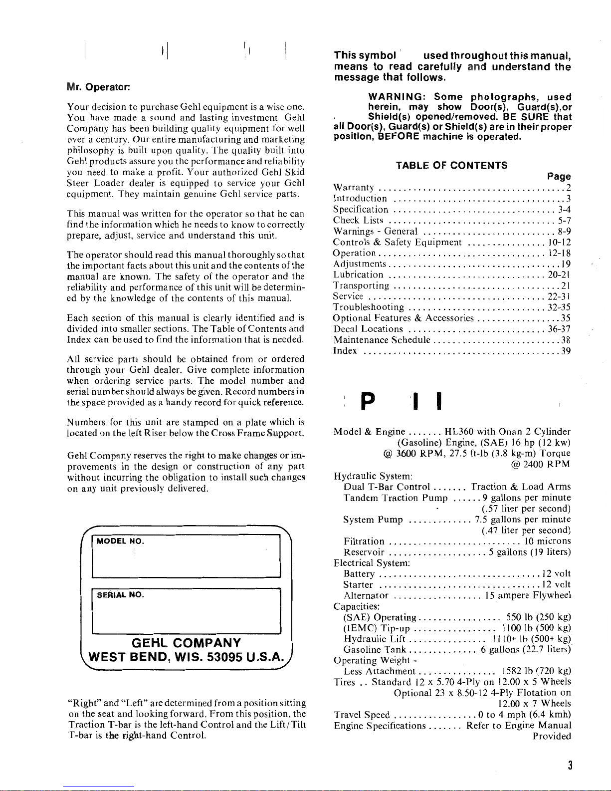
WEST BEND, WIS. 53095 U.S.A.
"Right"
on
the seat and looking forward.
Traction
T-bar
ill
to
purchase Gehl equipment
and
lasting investment. Gehl
has been building quality equipment for well
Our
entire manufacturing and marketing
is
built
upon
quality.
dealer
should read this manual thoroughly so
facts
are known. The safety
and
performance
of
your
Gehl dealer. Give complete information
should always be given. Record numbers in
is
equipped to service
about
this unit
of
the contents
this manual
to
find the information
reserves the right to ma
The
operator
to
and
of
the
of
this unit will be determin-
is
clearly identified
The
model number
or
construction
to
is
a wise one.
quality built into
and
reliability
your
so
that
he can
know to correctly
the contents
operator
of
this manual.
of
on
a plate which
Frame
ke
install such changes
and
and
Contents and
that
is
needed.
or
ordered
Support.
cha-nges
of
any
GEHL COMPANY
and
"Left" are determined from a position sitting
From
this position, the
T-bar
is
the left-hand
the right-hand Control.
Control
and
the
Lift/Tilt
Gehl
that
of
and
or
part
the
the
is
is
im-
This Symbol . used throughout this manual,
means
to
read carefully and understand the
message that follows.
WARNING:
A
all Door(s), Guard(s) or Shield(s) are in their proper
position, BEFORE machine
Warranty
Introduction
Specification
Check Lists
Warnings - General
Controls
Operation . . . . . .
Adjustments
Lubrication
Transporting
Service
Troubleshooting
Optional Features
Decal Locations
Maintenance Schedule
Index
herein, may show Door(s), Guard(s),or
Shield(s) opened/removed. BE SURE that
TABLE
......................
............
................
...............
& Safety Equipment
..................
............
......................
...........
...
..
.......................
SPECIFI
Model & Engine
(Gasoline) Engine, (SAE)
@ 1600
Hydraulic System:
Dual
T-Bar
Control
Tandem
System
Filtration
Reservoir
Electrical System:
Battery
Starter
Alternator
Capacities: .
(SAE) Operating
(lEMC)
Hydraulic Lift . . . . . . . . . . . . . .
Gasoline
Operating Weight -
Less
Tires
Travel Speed
Engine Specifications
Traction
Pump
.....................
....................
.........................
...............................
..............
Tip-up
Tank
Attachment.
..
Standard
Optional
...............
Some
OF
.........
................
.
........................
............................
& Accessories
..............
................
photographs,
is
operated.
CONTENTS
.
...............
.
........ . .............
.
..............
.. . ..
.... . .........
.
.................
..
....... . ......
...
. .
.. .. . ..
.
...
..
...........
.
.... . .. ..
. .
.
..........
.
.............
.
..
...........
. . .
..
..
...
CATIONS
.......
.............
.................
..............
HL360 with
RPM,
27.5 ft-lb (3.8 kg-m)
.......
Pump
.................
12
......
.
.. . 15
. . . . . . . . . . . . .
x 5.70 4-Ply on 12.00 x 5 Wheels
23
x 8.50-12 4-Ply
. . 0 to 4
.......
Refer
Onan
2 Cylinder
16
hp (12 kw)
@ 2400
Traction &
9 gallons per minute
(.57 liter per second)
7.5 gallons per minute
(.47 liter per second)
5 gallons (19 liters)
..
6 gallons (22.7 liters)
..
Load
.
.....
10
.
.......
ampere Flywheel
550 Ib (250 kg)
1100
Ib
1110+
Ib
1582
Ib
Flotation
12.00 x 7 Wheels
mph
to
Engine
used
Page
. . 3-4
5-7
8-9
10-12
12-18
....
20-21
22-31
32-35
...
....
36-37
..
. .
...
... . ..
Torque
RPM
Arms
microns
12
volt
. .
12
volt
(500 kg)
(500+ kg)
(720 kg)
(6.4 kmh)
Manual
Provided
19
21
35
38
39
on
2
3
3
Page 4
Attachments:
36" Utility Bucket
42" Utility Bucket
42" Light Material Bucket
48" Light Material Bucket
60" Light Material Bucket
Manure
36"
42"
Manure
36" Pallet
Accessory
Fork
Fork
Fork
.............
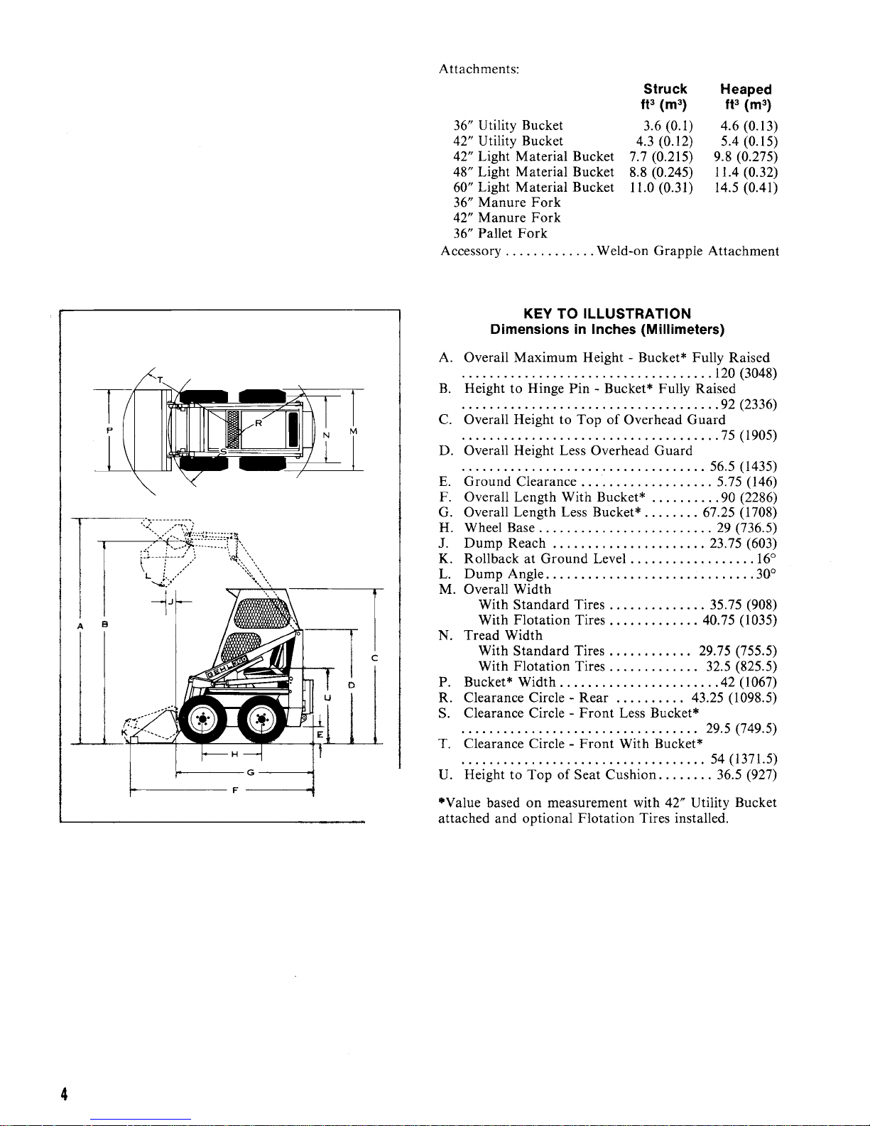
KEY
TO
Dimensions
in
Struck
fp (m3)
Heaped
fp (m3)
3.6 (0.1) 4.6 (0.
4.3 (0.
12)
5.4 (0.15)
7.7 (0.215) 9.8 (0.275)
8.8 (0.245) 11.4 (0.32)
11.0 (0.31)
14
.5
(0.41)
Weld-on Grapple Attachment
ILLUSTRATION
Inches (Millimeters)
13)
A B
A. Overall
.......................
·
B. Height
·
.... . ..
C. Overall Height
·
....................................
Maximum
to
Hinge
.....
..........
to
Height - Bucket* Fully Raised
.........
Pin
- Bucket* Fully Raised
.. ..
Top
of
Overhead
D. Overall Height Less Overhead
·
..................................
E.
Ground
Clearance
...... . ...........
F. Overall Length With Bucket* .
G. Overall Length Less Bucket* . .
H. Wheel Base .
1.
Dump
K. Rollback
L.
Dump
Reach .
at
Angle
.... . .....
.........
Ground
..............................
....
Level
....
..................
..
M. Overall Width
With
Standard
With
Flotation
N.
Tread
Width
Standard
With
With
Flotation
P. Bucket*
Width . ...
R. Clearance Circle S. Clearance Circle -
.......................
·
T. Clearance Circle -
..... . .. . .....
·
U.
Height to
Top
Tires
Tires
Tires
Tires
........
Rear
Front
Front
...
...... . .....
of
Seat
..............
..... ........
............
.............
..... . .....
. .
.......
Less Bucket*
.
..... . ..
With Bucket*
Cushion
...
....
. . ,
Guard
Guard
... . .....
..
....
.. . ..
...
...
.....
. 43.25 (1098.
. 29.5 (749.5)
..
...
........
120
(3048)
...
92 (2336)
75
(1905)
56.5 (1435)
. 5.75 (146)
90 (2286)
67.25 (1708)
29 (736.5)
23.75 (603)
16
30°
35.75 (908)
40.
75
(1035)
29.75 (755 .
32.5 (825.5)
42 (1067)
54
(1371.5)
36.5 (927)
°
5)
5)
4
·Value
based
on
measurement with 42" Utility Bucket
attached and optional
Flotation
Tires installed.
Page 5
HL360
-::0
(I)
3
o
<
(I)
o
(I)
II)
tD
""t
III
!!
tD
o
o
'<
"
l>
-
"tI
(I)
...
o
-
...
II)
-
0'
:l
-
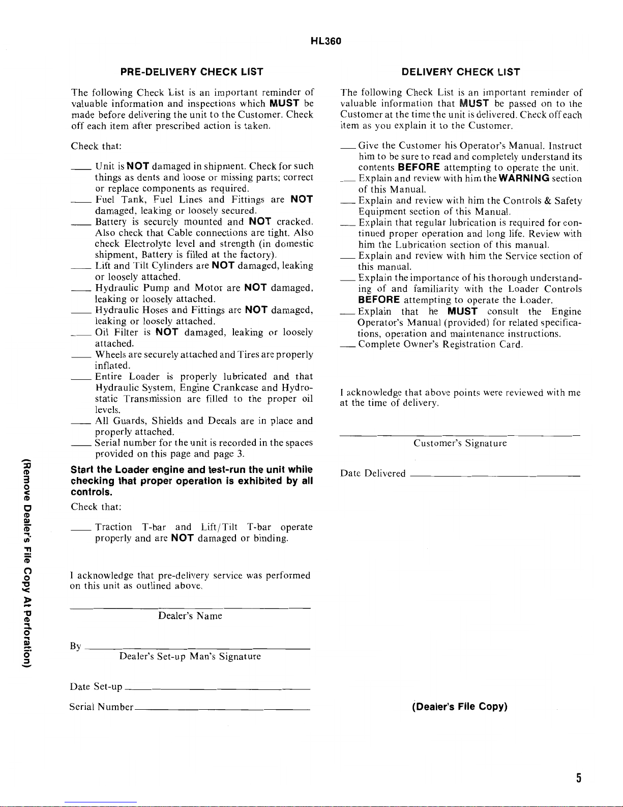
PRE-DELIVERY
The following Check List
valuable
made before delivering the unit
off each item after prescribed action
Check
__
__
__
__
__
__
__
__
__
__
__
Start the Loader engine and test-run the unit while
checking that proper operation
controls,
Check that:
__
I acknowledge that pre-delivery service was performed
on
By
Da
information
that:
Unit
is
NOT
things as dents
or
replace components as required.
Fuel
Tank,
damaged, leaking or loosely secured.
Battery
Also check
check Electrolyte level
shipment, Battery
Lift
or
Hydraulic
leaking
Hydraulic Hoses
leaking
Oil Filter
attached.
Wheels are securely attached
inflated.
Entire
Hydraulic System, Engine
static Transmission are filled
levels.
All Guards, Shields
properly attached.
Serial number for the unit is recorded in the spaces
provided on this page
Traction
properly and are
this unit
____________________________________
te
Set
is
and
Tilt Cylinders are
loosely attached.
or
or
Loader
as
outlined above .
Dealer's Set-up Man's Signature
-u p
_______________________________
and
damaged in shipment. Check for such
and
Fuel Lines
securely
that
Cable connections are tight. Also
Pump
loosely attached.
loosely attached.
is
NOT
is
T-bar
Dealer's Name
CHECK
is
an
inspections which
to
loose
or
and
mounted
and
is
filled
and
Motor
and
Fittings are
damaged, leaking
properly lubricated
and
Decals are in place
and
and
Lift/Tilt
NOT
damaged
LIST
important
the Customer. Check
missing parts; correct
Fittings are
and
strength (in domestic
at
the factory).
NOT
are
and
Crankcase
page
is
reminder
MUST
is
taken.
NOT
NOT
cracked.
damaged, leaking
NOT
damaged,
NOT
damaged,
or
loosely
Tires
are
properly
and
and
Hydro-
to
the
proper
3.
exhibited
T-bar
or
binding.
by
operate
of
be valuable information
that
oil
and
all
_
_
DELIVERY
The
following Check List
Customer
item
_ Give the
_ Explain
_ Explain and review with him the Controls
_ Explain
_ Explain and review with him the Service section
_ Explain the importance
- Explain
_ Complete
I acknowledge that above points were reviewed with
at the time
Date Delivered
at
the time the unit
as
you explain it to the Customer.
Customer
be
him to
contents
of this Manual.
Equipment section
tinued
him the Lubrication section
this manual.
ing
BEFORE
Operator's
tions,
sure to read and completely understand its
BEFORE attempting to operate the unit.
and
review with him the
that
regular lubrication
proper
of
operation
operation and long life. Review with
and familiarity with the Loader Controls
attempting
that
Manual
Owner
of
delivery.
Customer's Signature
___________________________
CHECK
is
that
M
his Operator's Manual. Instruct
of
this Manual.
of
to operate the Loader.
he
MUST
(provided) for related specifica-
and maintenance instructions.
's Registration
LIST
an
important
UST
be
is
delivered. Check off ea ch
WARNING
is
of
this manual.
his
thorough
consult the Engine
Card
reminder
passed on to the
section
& Safety
required for con-
understand-
.
of
of
me
_
Serial N umber
_____________________________
_
(Dealer's File Copy)
5
Page 6

6
Page 7
HL360
The
following
valuable
made
before delivering
off
eaGh item
Check
__
__
__
__
__
__
__
__
__
__
__
that
Unit
things as
or
replace
Fuel
damaged,
Battery
Also
check
shipment,
Lift
or
loosely
Hydraulic
leaking
Hydraulic
leaking
Oil
attached
Wheels
inflated.
Entire
Hydraulic
static
levels.
All
properly
Serial
provided
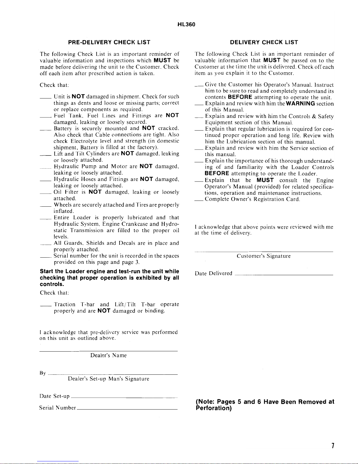
PRE-DELIVERY
Check
information
after
:
is
NOT
dents
Tank,
is
check
Electrolyte
and
Tilt
or
or
Filter
.
are
Loader
Transmission
Guards,
attached.
number
on
List
and
prescri bed
damaged
and
components
Fuel Lines
leaking
securely
that
Cable
Battery
Cylinders
attached.
Pump
loosely
Hoses
and
loosely
is
NOT
securely
is
System,
Shields
for
this
page
CHECK
is
an
inspections
the
unit
in
loose
as
or
loosely
mounted
connections
level
and
is
filled
are
and
Motor
attached.
Fittings
attached.
damaged,
attached
properly
Engine
are
and
the
unit
and
to
action
shipment.
or
and
filled
Decals
is
LIST
important
which
the
Customer.
is
taken.
Check
missing parts;
required
at
NOT
Crankcase
page
.
Fittings
secured
and
NOT
are
strength
the
factory).
damaged,
are
NOT
are
NOT
leaking
and
Tires
lubricated
to
the
are
recorded
3.
.
reminder
MUST
Check
for
correct
are
cracked.
tight.
(in
domestic
leaking
damaged,
damaged,
or
loosely
are
properly
and
and
Hydro-
proper
in place
in
the
spaces
of
be
such
NOT
Also
that
oil
and
Start the Loader engine and test-run the unit while
checking that proper operation
is
exhibited
by
all
controls.
Check
that
:
The
following
valuable
Customer
item as
_ Give
_
_
_
_
_
information
you
the
him
to
contents
Explain
of
this
Explain
Equipment
Explain
tinued
him
the
Explain
this
manual.
Explain
ing
of
BEFORE
-
Explain
Operator's
tions,
_
Complete
I
acknowledge
at
the
time
Date
Delivered
DELIVERY
Check
at
the
time
explain
Customer
be
sure
BEFORE
and
review
Manual.
and
review
section
that
regular
proper
Lubrication
and
review
the
importance
and
familiarity
attempting
that
Manual
operation
Owner's
that
of
delivery.
Customer's
_____
List
that
the
unit
it
to
the
his
to
read
and
attempting
with
with
of
lubrication
operation
section
with
to
he
MUST
(provided)
and
maintenance
Registration
above
points
_______
CHECK
is
an
important
MUST
is
delivered.
Customer.
Operator's
completely
him
the
him
the
this
Manual.
and
long
of
him
the
of
his
thorough
with
the
operate
consult
were reviewed
Signature
______
LIST
reminder
be
passed
Manual.
to
operate
WARNING
Controls & Safety
is
required
life. Review
this
Service
Loader
the
for
related
instructions.
Card.
on
Check
off
Instruct
understand
the
for
manual.
section
understand-
Controls
Loader.
the
specifica-
with
______
section
Engine
to
each
unit.
conwith
_
of
the
its
of
me
__
Traction
properly
I
acknowledge
on
this unit as
By
____________
Date
Set-up
Serial Number
T-bar
and
that
outlined
Dealer's
__
___
and
are
NOT
damaged
pre-delivery service was
above.
Dealer's
Set-up
______________________
__________________________
Name
Man's
Lift / Tilt
T-bar
or
binding
__
____
Signature
operate
.
performed
_
____
_
_
(Note: Pages 5 and 6 Have Been Removed at
Perforation)
7
Page 8
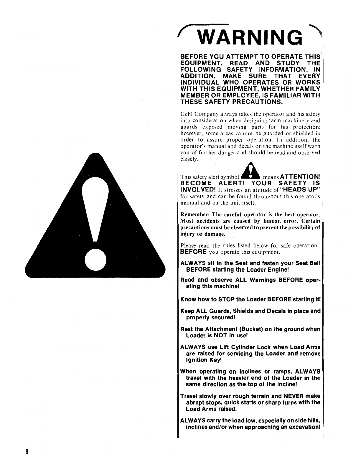
WARNING
BEFORE
EQUIPMENT,
FOLLOWING
ADDITION,
INDIVIDUAL
WITH
MEMBER
THESE
Gehl
into
guards
however,
order
operator's
you
of
closely.
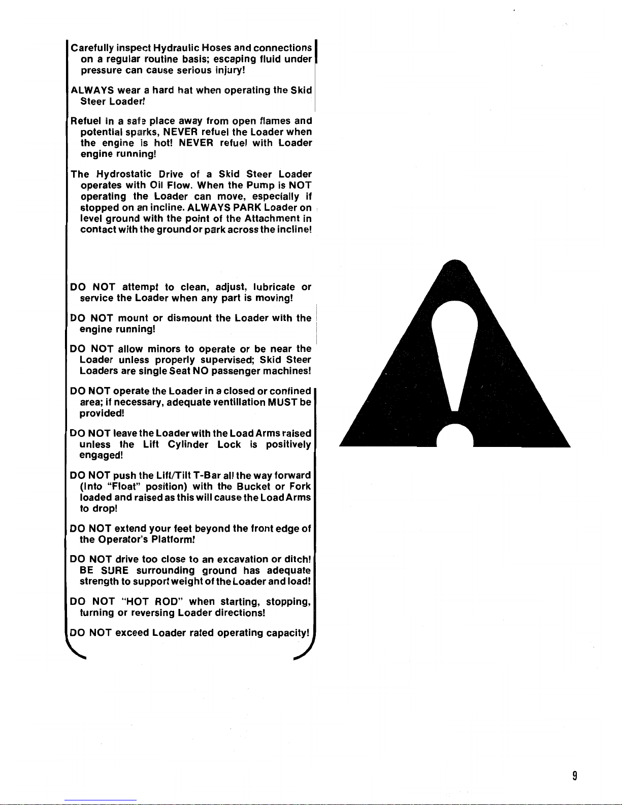
Thi"afoty
BECOME
INVOLVED!
for safety
manual
Remember:
Most
precautions must be observed
injury
YOU
ATTEMPT
READ
SAFETY
MAKE
WHO
THIS
EQUIPMENT,
OR EMPLOYEE, IS
SAFETY
Company
consideration
exposed
some
to
assure
manual
further
alec!
PRECAUTIONS.
always
when
moving
areas
cannot
proper
and
decals
danger
and
,ymbol
ALERT!
It
stresses
and
can
be
found
and
on
the
unit itself.
The
careful
accidents are caused
or
damage.
SURE
OPERATES
takes
designing
operation
should
A
an
operator
TO
OPERATE
AND
STUDY
INFORMATION.
THAT
OR
WHETHER
FAMILIAR
the
operator
parts
be
guarded
on
the
be read
mea",
YOUR
attitude
throughout
is
by
human
to
prevent the possibility
and
farm
machinery
for his
or
. In
addition,
machine
A
TTENTI
SAFETY
of
"HEADS
this
the best
error. Certain
protection;
shielded in
and
THIS
THE
IN
EVERY
WORKS
FAMILY
WITH
his safety
and
the
itself
warn
observed
ON!
IS
UP"
operator's
operator.
of
Please read
BEFORE
the
rules listed below for safe
you
operate
this
equipment.
operation
ALWAYS sit in the Seat and fasten your Seat Belt
BEFORE starting the Loader Engine!
Read
and observe ALL Warnings BEFORE oper-
ating this machine!
Know how to STOP the Loader BEFORE starting it!
Keep ALL Guards, Shields and Decals in place and
properly secured!
Rest the Attachment (Bucket) on the ground when
Loader is NOT
ALWAYS use
In
use!
Lift
Cylinder Lock when Load Arms
are raised for servicing the Loader and remove
Ignition Key!
When operating on inclines or ramps, ALWAYS
travel with the heavier end
as
same direction
the top of the incline!
Travel slowly over rough terrain and
abrupt stops, quick starts
of
the Loader in the
NEVER
or
sharp turns with the
make
Load Arms raised.
8
ALWAYS carry the load low, especially on side hills,
inclines and/or when approaching
an
excavation!
Page 9
Carefully inspect
on a regular routine basis; escaping fluid
pressure can cause serious injury!
ALWAYS wear a hard hat when operating the Skid
Steer Loader!
Refuel in a safe place away from open flames and
potential sparks, NEVER refuel the Loader when
the engine is hot! NEVER refuel
engine running!
The Hydrostatic Drive
operates
operating the Loader can move, especially
stopped on
ground
level
contact
DO
service the Loader when any
DO
engine running!
NOT
NOT
with the
mount
Hydraulic
with
Oil Flow. When the Pump is
an
incline. ALWAYS PARK Loader on
with
the
ground
attempt
to
or
dismount
Hoses
of
point
or park
clean, adjust, lubricate
and
a Skid Steer Loader
of the Attachment in
across the incline!
part
is moving!
the Loader
connections
under
with
Loader
NOT
if
or
with
the
DO
NOT
allow minors
Loader unless
Loaders are single Seat NO passenger machines!
DO
NOT
operate the Loader in a closed
area; if necessary, adequate ventillation
provided!
NOT
DO
unless the
engaged!
DO
(Into
loaded and raised
to drop!
DO
the Operator's Platform!
DO
BE SURE surrounding
strength to
DO
turning
DO
leave the Loader
Lift
NOT
push the
"Float" position)
NOT
extend
NOT
drive
NOT
or
NOT
exceed Loader rated operating capacity!
your
too
support
"HOT
reversing Loader directions!
to
operate
properly
Cylinder
LiftITiit T-Bar
as
close
ROD" when starting, stopping,
supervised; Skid Steer
with
with
this
will
feet beyond the
to
an excavation
ground
weight
of
or
be near the
or
confined
MUST
the Load Arms raised
Lock
the Bucket
cause the Load
the Loader and load!
is positively
all the way forward
or
front
edge
or
ditch!
has adequate
be
Fork
Arms
of
9
Page 10
Gehl Company, in compliance with the
Agricultural Engineers, has
adopted
Farm
and Industrial Equipment Institute
and
the American Society
of
as a SAFETY ALERT SYMBOL. When you see this symbol, in this
BE
ALERT! Your Safety
is
involved.
CONTROLS & SAFETY
Whenever and wherever possible
machine operation, Guards and Shields have been used
on this equipment to protect potentially hazardous areas.
In many places, Decals are also provided to warn
potential dangers
proced ures.
WARNING:
A
factory installed Guards and Shields are properly
secured
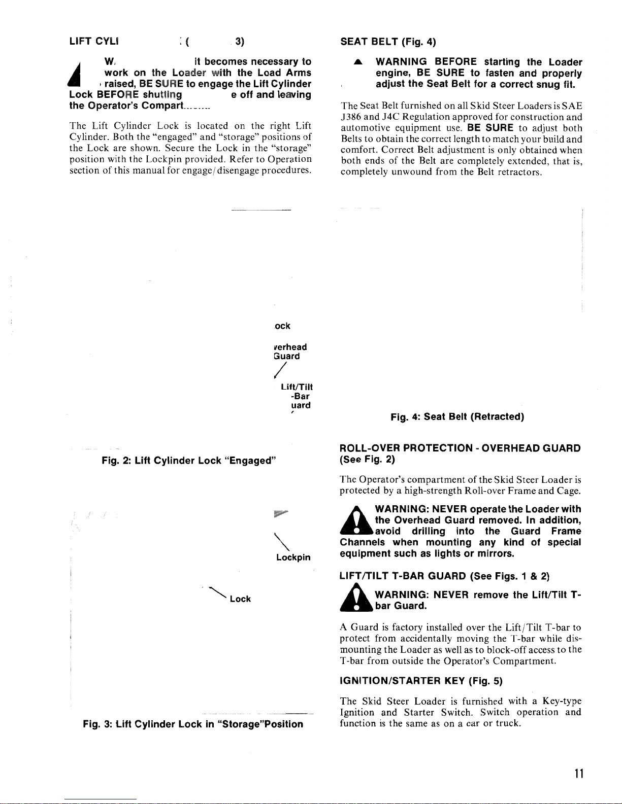
T -BARS (Fig. 1)
A
bar Controls to their "Neutral" positions, BEFORE
starting the Loader engine.
warning.
DO
in
WARNING:
Seat Belts,
Pump Drive Belt Idler and to return both
Traction
T~Bar
as
well as to display special operating
Read and observe ALL
son
the
NOT
operate this equipment unless
place.
BE
SURE to Fasten and Adjust
to
disengage the Hydrostatic
and
without affecting
of
unit BEFORE operating it.
ALL
T-
manual
or
on the unit itself, you are reminded to
EQUIPMENT
NOTE: When seated
•
Traction
the Lift/Tilt T -bar
Traction T-bar
The
Traction T-bar controls forward
and turning the Skid Steer Loader. With the Hydrostatic
Pump
Drive Belt Idler engaged, a right
out
by twisting the Traction
is
carried-out
clockwise.
power, turns in either direction should only be carriedout
with the Traction T
The
"Neutral" position
movements for turning, forward travel
are displayed on the
Operator's Console.
Lift/Tilt T -bar
The
Lift/Tilt
Load Arms
back. Pushing the
"N
eutral" position lowers the
the
T-bar
straight back raises the
bar
clockwise extends the Tilt Cylinders to roll the
Bucket or
counterclockwise retracts the Tilt Cylinders
Bucket or
T-bar
is
by
twisting the
By
design
and
T-bar
and
rolling the Bucket
Lift/Tilt
Fork
Fork
back .
"Operation"
controls raising and lowering the
forward. Twisting the
on
the Loader Seat, the
is
the "left-hand" control and
the "right-hand" control.
and
reverse motion
turn
in carried-
T-bar
clockwise. A left
Traction
for most efficient use ofLoader
-bar
in the "Neutral" position.
of
the Traction
T-bar
Load
Load
T-bar
counter-
T-bar
and
and
reverse travel
Decal on
or
straight forward from
Arms. Twisting the T-
top
Fork
forward
Arms. Pulling the
to
roll the
turn
T-bar
of
the
or
T-bar
Fig. 1
10
NOTE: The Lift/Tilt T -bar
•
equipped with 3-Spool Control Valves and
Auxiliary Hydraulics connections
with a Float
the T -bar
Information topic
manual for further explanation.
A
when the Load Arms are raised.
pOSition
all
the way forward. Refer
WARNING: On 3-Spool Control Valve
Loader models, NEVER
bar fully forward into the "Float" position
which
in
the Operation section of
on
is
reached
push
Loader models
is
also
to
the Lift/Tilt
equipped
by
pushing
the General
this
T-
Page 11
LIFT CYLI NDER LOCK (Figs. 2 & 3)
SEAT BELT (Fig. 4)
WARNING: When it becomes necessary to
on
A
Lock BEFORE shutt
the Operator's Compartment.
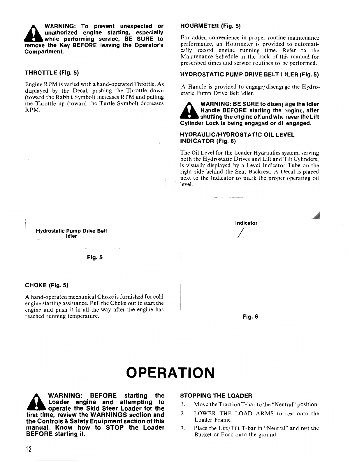
The Lift Cylinder Lock
Cylinder. Both the "engaged"
the Lock are shown. Secure the Lock in the "storage"
position with the Lockpin provided. Refer to
section
work
raised,
of
this manual for engage / disengage procedures.
the Load
BE
SURE to engage the Lift Cylinder
er w
ith
the Load Arms
in
g the engine off and leaving
is
located
and
on
the right Lift
"storage" positions
Operation
of
WARNING BEFORE starting the Loader
A
The
1386
automotive equipment use.
Belts to obtain the correct length to match your build
comfort. Correct Belt adjustment
both
completely unwound from the Belt retractors.
engine,
adjust the Seat Belt for a correct snug
Seat Belt furnished
and
J4C
ends
BE
SURE
Regulation approved for construction
of
the Belt are completely extended,
A~
CARRY tOAn
to
fasten and properly
on
all Skid Steer Loaders
BE
SURE to adjust
is
only obtained when
LOW
is
that
fit.
SAE
and
both
and
is,
Fig.
Fig.
3:
2:
Lift Cylinder Lock "Engaged"
lift
Cylinder Lock
in
"Storage"Position
Fig.
4:
Seat Belt (Retracted)
ROLL-OVER PROTECTION - OVERHEAD GUARD
(See Fig. 2)
The Operator's
protected by a high-strength Roll-over
WARNING: NEVER operate the Loader with
A
Channels when mounting
equipment such
LlFTITILT T-BAR GUARD (See Figs. 1
the Overhead Guard removed. In addition,
avoid drilling into the Guard Frame
compartment
as
lights or mirrors.
A WARNING: NEVER remove the Lift/Tilt
"bar
A
Guard
protect from accidentally moving the T-bar while dismounting
T-bar
IGNITION/STARTER KEY (Fig. 5)
The Skid Steer
Ignition
function
Guard.
is
factory installed over the Lift
the
Loader as well as
from outside the Operator's Compartment.
Loader
and
Starter
is
the same as
of
the Skid Steer
Frame
any
kind
to
block-off access
is
furnished with a Key-type
Switch. Switch operation
on
a car or truck.
of
& 2)
/Tilt
Loader
and
special
T -
Cage.
bar
to
the
and
is
T-
to
11
Page 12
WARNING: To prevent unexpected or
A
remove the
Compartment. .
THROTTLE (Fig. 5)
Engine
displayed
(toward the
the Throttle up (toward the Turtle Symbol) decreases
RPM.
unathorized engine starting, especially
while performing service,
Key
BEFORE leaving the Operator's
RPM
is
varied with a hand-operated Throttle. As
by
the Decal, pushing the Throttle down
Rabbit
Symbol) increases
BE
RPM
SURE to
and pulling
HOURMETER (Fig. 5)
For
added convenience in proper routine maintenance
performance, an
cally record engine running time. Refer to the
Maintenance Schedule in the back
prescribed times and service routines
HYDROSTATIC PUMP DRIVE BELT ID
A Handle
Pump
static
WARNING:
A
Cylinder Lock
HYDRAULIC/HYDROSTATIC OIL LEVEL
INDICATOR (Fig. 6)
The Oil Level for the Loader Hydraulics system, serving
both the Hydrostatic Drives and Lift and Tilt Cylinders,
is
right side behind the Seat Backrest . A Decal
next
level.
Handle BEFORE starting the engine, after
shutting the engine off and whenever the
visually displayed by a Level Indicator Tube on the
to
the Indicator to
Hourmeter
is
provided to engage/ disenga
Drive Belt Idler.
BE SURE
is
being engaged or disengaged.
is
provided to automati-
of
this manual for
to
be
ge
to
disengage the Idler
mark
the proper operating oil
performed.
LER
(Fig.
the Hydro-
is
placed
5)
Lift
Fig. 5
CHOKE (Fig. 5)
A hand-operated mechanical Choke
engine starting assistance. Pull the Choke
engine
reached running temperature .
and
push it in all the way after the engine has
is
furnished for cold
out
to start the
OPERATION
WARNING:
A
first time, review the
the Controls & Safety Equipment section of this
manual.
BEFORE
Loader engine and attempting to
operate the Skid Steer Loader for the
Know
starting it.
BEFORE
WARNINGS
how to
STOP
starting the
section and
the Loader
Fig. 6
STOPPING THE LOADER
1.
Move the Traction T
2.
LOWER
Loader Frame.
3.
Place the Lift /Tilt
Bucket
or
THE
Fork
-bar
LOAD
T-bar
onto
the ground.
to
the "N eutral" position.
ARMS
in "Neutral" and rest the
to
rest onto the
12
Page 13

4.
Move the Throttle to the Idle position.
5.
Disengage the Hydrostatic
6.
Turn
the Ignition Key to "OFF" and remove the
Key.
7.
Make sure
has stopped, detach the Seat Belt
the Operator's Compartment.
BEFORE STARTING THE ENGINE
Before actually starting the engine
Loader, familiarize yourself with the T
orient your mind
Grasp the T-bars
directions
Loader, Load Arms and Tilt Cylinders.
that
all movement
and
coordinate your
and
move them in the
to
simulate the various movements
Pump
and
Drive Belt Idler.
Loader motion
and
climb
out
and
running the
-bar
operation
hand
movements.
appropriate
of
of
to
the
Attempt all raise and lower operations, Bucket roll-
and
forward
the two functions before proceeding to operate
bars at the same time.
in
Skill
through proper coordination
and reverse travel with raising and lowering the
Arms
and
back.
To
until they happen naturally and without mistake
hesitation.
A
T-bar operations
caution and good judgement while running this
equipment.
roll-back operations and combinations
Skid Steer Loader operation
of
with rolling the Bucket
gain proficiency, practice all
WARNING: Operation
Loader at full Throttle should only
attempted after complete familiarity with all
is
known. ALWAYS exercise
is
only obtained
the Loader's forward
or
Fork
forward
T-bar
operations
of
the Skid Steer
both
Load
of
T-
or
or
be
STARTING THE ENGINE
I. Step up onto the back
clim b backwards
Compartment.
A
2.
3.
4.
5.
6.
7.
WARNING: FASTEN AND PROPERLY
ADJUST the Seat Belt BEFORE proceeding.
Check
position and check
Drive Belt Idler
Move the Throttle to the midway point ofits travel.
F or cold engine starts, pull the
out.
Turn
Make
the Choke all the way in after the engine reaches
proper operating temperature.
Before attempting
Drive Belt Idler, roll the Bucket
completely
for several seconds
that
both T-bars are in their "Neutral"
the Ignition Key
appropriate
and
of
the Bucket
into
that
the Hydrostatic
is
disengaged.
to
start
Choke
to
hold this Lift / Tilt T
to
readjustments
engage the Hydrostatic
speed-up oil heat-up process.
the
Choke
the
engine.
or
Operator's
or
-bar
Fork
and
Pump
all the way
and
push
Pump
Fork
back
position
NOTE: To prolong Loader component life,
•
avoid "jackrabbit" starts,
bar movements.
LIFT CYLINDER LOCK (Figs. 7
WARNING: When
on
A
Lock BEFORE shutting the engine off and leaving
the Operator's Compartment.
remove the Ignition
work
raised,
the Loader with the Load Arms
BE
SURE
Key.
stops
and
forceful
&
8)
it
becomes neccessary to
to
engage the Lift Cylinder
BE
SURE also
T-
to
FIRST TIME PRACTICE RUNNING
WARNING:
used
A
an
empty Bucket or Fork.
Smoothest and most efficient
achieved while the engine
Throttle. After the engine
engage the Hydrostatic
and deliberately move the Traction T
forward, using a firm left-hand grip
extension. Attempt all forward, reverse and turning
operations before proceeding to operate the Lift /Tilt T-
bar. Leaving your left hand off the Traction T-bar, slowly
and deliberately pull the
using a firm right-hand grip
for test-running
and
obstructions. Operate the Loader with
BE
SURE that the area being
is
being operated
is
sufficiently warmed-up,
Pump
Drive Belt Idler
Lift/Tilt
and
is
clear of spectators
Loader
T-bar
right-arm extension.
opeation
at
half to full
and
-bar
straight
and
left-arm
straight back,
is
slowly
Fig.
7:
Lift Cylinder Lock "Engaged"
13
Page 14

Fig.
8:
Cylinder Lock
Engaging Lock
Before proceeding
to prevent Loader movement, first disengage the Hydrostatic
Pump
to
Drive Belt Idler.
in
"Storage" Position
engage the Lift Cylinder Lock
and
3.
After the Lock
Lock with the left hand and continue to lower the
Load Arms down until they contact the Loader
Frame. With the
off and secure the Lockpin to place the Lift
Cylinder Lock back into the "storage" position.
GENERAL INFORMATION
WARNING: Fasten and properly adjust the
A
BEFORE starting
If
being operated
will stop rising
Lower the Load Arms
before attempting to restart the engine.
engine kills while the Lift/Tilt
lower the Load Arms, the Arms will continue
until they rest against the Frame. Return the T
"N
Braking - Stopping Loader Motion
Seat Belt BEFORE starting the Loader
engine. Know
the Loader engine kills while the Lift / Tilt T
eutral" before attempting to restart the engine.
is
cleared completely, release the
Load
Arms down, shut the engine
how
to
stop
the Loader
it.
to
raise the Load Arms, the Load Arms
and
hold at the level already reached.
and
return the T
T-bar
-bar
to "Neutral"
If
the
is
being operated to
-bar
Loader
to
lower
-bar
is
to
1.
Remove the Lockpin from the Cylinder Lock.
2.
Raise the
to
3.
Lower the Load Arms slightly until the Lock firmly
rests against the Cylinder.
NOTE: DO
•
Lock NOR continue
after the Lock contacts the Cylinder to avoid
damaging the Lock
Disengaging the Cylinder Lock
WARNING:
A
Two methods can be followed
Lock back into its "storage" position.
method
while the Loader Operator raises the
after the Lock
back into "storage".
An alternative method of disengaging the Lock
as
1.
Hydrostatic Pump Drive Belt Idler BEFORE
proceeding.
follows:
Raise the Load Arms slightly away from contact
with the Lift Cylinder Lock.
Load
Arms far enough
drop
down around the Cylinder Rod.
NOT
drop the Load
to
or
the Cylinder.
BE
SURE to disengage the
to
is
to
have a second person disengage the Lock
is
released, the second person also locks it
to
allow the Lock
Arms
lower the Load Arms
disengage
and
The
recommended
Load
Arms. Then,
onto the
secure the
is
to
do
so
of
The Hydrostatic Drive Pumps
control braking and stopping Loader forward
reverse movement. When the Traction T
the straight "Neutral" position, all movement
Wheels
Traction T-bar gradually
and
Load
Positions
HL360 Skid Steer Loaders are available in 2-Spool
3-Spool Control Valve models. Models with 3-Spool
Control Valves are factory equipped with Auxiliary
Hydraulic connections
"detent", on the Lift / Tilt T
position for the Auxiliary Hydraulics connections.
The
pushing the
position causes oil flow to effectively bypass the Lift
Cylinders thus allowing the
following the ground contour.
A
Auxiliary Hydraulics connections), all the way
forward into the "Float" position when the Load
Arms are raised.
is
stopped.
stop the Wheels .
Arm
"Float"
WARNING: NEVER push the LiftlTIIt T-bar,
on
Valve (characterized
By
all means,
and
FLoat & auxiliary Hydraulics "Detent"
and
position for the Lift/Tilt T-bar
T-bar
a unit equipped with 3-Spool Control
all the way forward. This
the Skid Steer Loader
and
-bar
is
moved to
of
the
BE
SURE to move the
deliberately
feature a Load Arm Float,
-bar
as
Load
Arms to "float" while
by
to
slow-down
and
well as a "detent"
is
reached by
T-bar
Foot Pedals and
2.
Using the left hand, reach
of
corner
Lock up so
the Lock can be cleared by the Cylinder when the
Load
the Overhead
that
the Cylinder can be retracted
Arms are lowered.
Guard
around
and
14
the top right
lift
and
hold the
and
The "detent" position for the Auxiliary Hydraulics
is
connections
Foot
Pedal all the way down. The Auxiliary Hydraulics
"detent" position enables operations
accessories, from outside the Operator's Compartment.
reached
by
pushing the "toe" end
of
of
the
special
Page 15

NOTE: HL360
•
2-Spool
T
-bar
Float Position NOR
connections.
Control
Skid
Valves
Steer
do
Loader
NOT
have a
Auxiliary
models
with
Lift/Tilt
Hydraulics
Digging & Loading
To
dig with and load the Bucket, first lower the Load
Arms down in contact with the Loader
(Figs.
9,
10,
11
& 12)
Frame
and
roll
the Bucket Cutting Edge down in contact with the
as
ground. Move the Loader into the material and,
RPM
engine
at
and,
T
-bar
to decrease travel speed while still maintaining
loads-down, roll the Bucket back slowly
the same time, gradually pull back
on
the Traction
the
Wheel torque.
NOTE:
•
when
working
move the
forward,
Loader
working
ability
travel speed is decreased.
ability
from
through
Traction
its
"Neutral"
maximum
T-bar
only a slight
position,
is increased
For
optimum
Wheel torque,
amount
while
filling
a
Bucket.
J""
...
;
J.
,
",,,
..,
"t
."
't
..
-------._
...
_----------------_.
: ' ,
..
' "
\
.\,~
,
to
,
.,:\.", t'"'-
: , ..,'
\:
:
~'''''''''''''~
~
:',':
~
,
~ ,:
~ ;': L'~ '~":' :' ~~,';:
,". ' .
I
\,.-.."
\.
..
-
......
_------------_
__
\.,,~
,I'
""):
t'
I.
'
~ ',',
S
,-",,
',~,"',
.:~~ ,','~"
":'\
"'.~
~
,.'"
n,'l • \.,~:
~~"~~
:~" " ~
'.1
~
~
'.
" ,
... ...
",'
.....
...
_-_
......
I
1
.
I •
1..
",",'.;,'
•••
.'
.
\
'
/
.................................................
· .
•
·
·
•
·
•
•
·
·
:
" "'
s\~
- \ .
..
',
:
.\\\':
· .
· .
· .
i
~
:
~:
i
:
\.~,:
:
~-,~
:
:
~,~\:
· .
\':~~
'-'
~-:
,
.
.
I..
..~,...\,.......
. \
Fig.9
Fig.10
In most hard-packed materials, to fill the Bucket it
necessary
back. Avoid driving onto the material if
to
raise the
Load
Arms while rolling the Bucket
at
is
also
all possible.
With the Bucket filled, back the Loader away from the
material
rest the Load Arms down
onto
the
Frame
and
before proceeding to the dumping area.
WARNING:
or
A
.
incline
(loaded
Fork
the
Loader
or
ramp, ALWAYS travel
Bucket
ALWAYS
LOW
with
Frame. When
end)
toward
carry a loaded
the
Load
Arms
operating
with
the
top
Bucket
resting
on an
the heavier
of
the
incline.
on
end
15
Page 16

,'
...
..........
..................
\:
~ "
\
\.
... .....
1,
\,
...
-
."" '-""~
_----
_.
.....
.....
', " S \
__
..
_-_..
__
...........
,
,
, .
\
.'
I..L_'~" _''''
••••
\
,
,
,
I ,
I ,
I
I
i
~
:
i
~
:
:
,~,:
:
~":
:
~J~:
\':
~-'-'
~
':
S
:'~:.:~;~\..,~"~.
~ ~,\::~:
'L~:'~~ '
','
~ ~.:~'~'~',:
,:. :'~,'
~:
~
-''-1, '
\"-.."".-
,"
..
".',.~
I
\.----_._-------------_
~
~
~
S
...
_---)
I '
I..
c,:;·
.x·
...
....
I
I
I
I
Fig.11
Dumping the Bucket or Fork
Onto
a Pile
Carry
the loaded Bucket
or
Fork
low unt il reaching the
pile. Then, stop forward motion and raise
high enough so
the pile.
Then
the Bucket
Empty the Bucket
while lowering the Load Arms
Fork
back.
Into
a Box
Carry
the loaded Bucket
truck, trailer
box.
Then, stop
of
the
box to raise the
box. Slowly move the
Bucket
or
material
Load
the
that
the Bucket
, slowly move the
or
Fork
to spill the material
or
Fork
or
spreader box squarely with the
or
or
Loader
and
and
Fork
Fork
back the
rolling the Bucket
low and
forward motion well away from
Load
Arms and clear
Loader
Fork
over the inside
is
dumped, back away from the
ahead
of
the box. After the
Arms while rolling the Bucket
ahead
on
the
Load
clears
to position
top
Loader
approach
the
to
position
box
or
Fork
Arms
the
top
of
ofthe
pile.
away
or
the
sideofthe
the
side
side ofthe
the
and
lower
back.
Fig. 12
NOTE: A Bucket can be conveniently used to
•
spread the pile inside the box
by
positioning
the Bucket Cutting Edge against the near side of the
pile and rolling the Bucket back while slowly driving
forward and pushing the top of the pile forward.
Over a Solid
A
Embankment
WARNING: DO
excavation or ditch!
NOT
drive too close
BE
SURE surrounding
ground has adequate strength
to
support
to
an
weight of the Loader and load!
Carry
the
loaded Bucket
the
toward
where
of
the embankment.
forward
After
emb
the Bucket
dumping area.
the
Bucket
and
raise
the
material
ankment while
or
or
the
Fork
or
Fork
Stop
the
Loader
Fork
extends half-way over
Then
, roll
the
Load
Arms to
is
dumped, back away
lowedng tbe
Load
back
low while traveling
at
the position
the
edge
Bucket
dump
or
Fork
the material.
from
the
Arms and rolling
16
Page 17

Scraping with a Bucket (Figs. 13 & 14)
Both HL360 Skid Steer Loader models, units with either
2-Spool
scraping with a Bucket attached
or
3-Spool Control Valves,
to
the
can
be used for
Load
Arms.
For
scraping, the Loader should be operated in the forward
direction. First position the
Load
appropriate level which allows the Bucket
place the Bucket Cutting Edge
at
Arms
to
be tipped to
a slight angle
at
to
the
the
surface being scraped. While traveling forward with the
Bucket in this position, material can flow over the
and
Cutting Edge
collect inside the Bucket.
...
·
•
·
·
·
•
·
·
·
·
·
•
·
·
·
·
..................
.~.
---
..
-
_._.
-----
---_
........
---
---_
.. ----
--- -- - - -
.......
\
\
l _
___
___ __ . __ .
_--_
~
\"
.....................
,'
.. ','
." S
. .
,\,,,-,.,,~
_____ . __
.....
....
..
.
\
\
.l
\,';'
:~
.....
'
Fig.14
· ·
·
· .
· .
· .
:
:
:
:
:
· .
\'::
·
·
,
"""""",''
\'
:
.~\\:
~ l"'
,,\H'-;:\
~
:
~:
\.~,:
~,~:
~~,:
'
~'.~~
-:
~ )~,Y
:
\.,' .\:
:
~''''''''''''~
:
~
:
~
•
·
:
~"_\:~:~
1.._
--- ---------------------
L'~
~:',"~<~,:~T ~ '::~
,,'" ~"l" ~
1,~,1,'v
n
.'l \ "'~:
: '~'~':~:
~\
,',~
~' ~
~,\:
:::~~~',:~
"
I"
~
·:u~
Fig.13
.
,.
~
""
Leveling with a Bucket (Fig. 15)
NOT
.
E:
.
,
.
\
:
,,
:
\
•
Load Arms
equipped with the Float "detent" feature, that
HL360 with 3-Spool Control Valve and Auxiliary
Hydraulics.
Levelin~
First drive the Loader
:
-,
levelled. Then, with the Load Arms down against the
Frame, push the Lift / Tilt T-bar into the Float position
with a Bucket attached to the
is
best accomplished with a Loader
to
the outer edge
of
the area to be
is,
an
and roll the Bucket forward to place the Bucket Cutting
at
Edge
Proceed to level the area
a 30 to 45° angle to the surface to be levelled.
by
driving the Loader
backward.
17
Page 18

( ..................................................\
, ,
, ,
, ,
:
" -~
"
",' ,
:
~"
:
~q;
,
."
:
\~
i~
~
,
,
,
,
,
,
,
:
~~~~
~
\,,~
...
-.~~~~,
~,
..
'.'"
''
.
..
"
.......
"'~
...........~ ..\
s
:
,~'
\
\~
:."
........
:
.~:
,
~
\
.....
~',~}
:
~
,
~.
:'~"
.
\'
"'\ \
1"
, ,
,
\ , '
l"_;~\
.....
:
~
.
~
\
\
':
:
:
\
:
\
,
\
\
\
\
\
\
\
,
\
,
\
·'
Fig. 15
Bucket and Fork Mounting (Figs. 16 & 17)
HL360 Buckets and Forks are designed for quick and
convenient attachment and detachment.
Bucket or Fork, approach
it
from the rear with the Load
To
attach a
Arms resting against the Frame and the Tilt Cylinders
partially extended. Drive the Loader against the back of
the Bucket or
Attachment Plate in front
the Attachment Lip on the back
Fork
head-on and squarely so that the
of
the Load Arms slides under
of
the Bucket. With the
Lip positively engaged, retract the Tilt Cylinders
completely. Then, shut off the Loader engine, leave the
Operator's Compartment and jnstall the Attachment
Pins and Lockpins in the position and direction shown.
To detach the Bucket or Fork, reverse the process.
Fig. 16
Fig.
17
Auxiliary Hydraulics (Fig. 18)
HL360 Loader models with 3-Spool Control Valve and
Auxiliary Hydraulics connections have a
control mechanism to operate a secondary device, such
Foot
Pedal
as
a Grapple Attachment. Pushing the Pedals with the toe
closes the Grapple. Pushing the Pedals with the heel
opens the Grapple. Both Pedals are welded onto a
common Shaft.
all
the
way
NOTE: Pushing the Pedals
•
with the toe engages the "detent" position
oil
enabling continuous
flow.
down
WARNING: ALWAYS install or remove the
A
Attachment
Pins
and
Lockpins with the
engine shut OFF and the Load Arm
LOWERED completely.
18
Fig. 18
Page 19

ADJ
U
STME
NTS
Simplicity
minimum
proper Loader operation.
•
provided, it
day.
A
or when it
ENGINE
All information related
operating settings
Manual
HYDROSTATIC
After break-in and through the course
operation, the Hydrostatic
and stretch .
•
and adjust Drive Belt tension
excessive Belt wear
Sheaves using details provided
Alignment topic
manual. If Belt tension
NOT
slip and wear faster. I mproper Belt tension likewise
causes excessive wear and early failure.
of
HL360 design and functions makes for a
amount
NOTE:
day" basis and since
WARNING: Refuel
open flames and potential sparks. NEVER
refuel the Loader while the engine
is
furnished with the Loader.
NOTE: After the first 10 hours of operation and
at regular 10 hour intervals thereafter, check
disengage. If tension
of
readjustment required to maintain
If
the Loader
is
advisable to refuel before starting the
HOT.
is
PUMP
is
in
is
operated
NO
in
a safe place away from
to
engine adjustments and
detailed in the separate Engine
DRIVE BELT (Fig. 19)
Pumps
noted,
the Service section of this
BE
is
too tight, the Pumps will
is
too loose, the Belt will
on
a "day-to-
gasoline gauge
is
running
of
normal
Drive Belt will wear
as
necessary.
SU
RE
to
realign the
in
the Sheave
is
If
WARNING: The above procedure
A
with the engine running and the Loader
position. Shut the engine off and carefully leave the
Loader to block it up BEFORE attempting
the engine or to perform any adjustment or service
routines. DO
maintain this position without additional blocking
or supporting.
With the Loader Tires off the ground, shut the engine off
and remove the Ignition Key. Next, remove the Seat
assembly for access to the Drive Belt. Then, loosen (bu t
do
Pump
up as far as possible and snug the
the Plate in this positions.
the Loader should only
DO
NOT
leave the Operator's Compartment
NOT
rely on the Loader Hydraulics to
NOT
remove) the (4) bolts which secure the Idler and
Mounting Plate to the
be
used for just
Frame
. Then, pry the Plate
(4)
bolts enough to hold
for
to
raising
that.
in
this
restart
WARNING: Attempt Belt tension readjust-
A
adjust Belt tension, the Loader Wheels
rotate. Refer to Service section for "Neutral"
adjustment.
To readjust the
and properly block the Loader up so
are
Raising the Loader can
first placing two equal height (approximately
solid blocks
rear Wheels and under the rear corners
Frame
Idler disengaged
Loader Frame, extend the Tilt Cylinders to roll the
Bucket and pick the Loader off the ground; stop when all
four
ment ONLY after the correct Traction T -bar
"Neutral" position
Pump
NOT
touching the ground.
of
wood (at least 2 feet long) parallel with the
. Then, with the Hydrostatic
and
Tires are off the ground.
is
established.
Drive Belt tension, first carefully
that
be
conveniently accomplished by
Pump
the
Load
Arms down against the
To
MUST
all
four
5-1 / 2"
of
the Loader
Drive Belt
safely
NOT
Tires
tall)
Fig. 19
Then, making sure
"Neutral" position
start the Loader engine and note
are turning. Next, using a rubber malet
tap the corners
amounts until the
shut
the engine off and remove the Ignition Key and
proceed to tightly secure the (4) bolts to fix the Idler and
Pump
Mounting Plate position.
that
the Traction T-bar
and
with the
of
the Plate down slightly and in equal
Pump
Pump
Idler disengaged,
that
the
or
Sheaves stop turning. Then,
is
Pump
Sheaves
lead hammer,
in the
19
Page 20

LUBRICATION
WARNING: NEVER attempt to lubricate the
A
unauthorized or unexpected starting.
•
GENERAL INFORMATION
•
operation. Repeat lubrication and
regular 50 hour intervals thereafter. Under more
strenuous operation and/or
weather conditions or dusty conditions, change oil
and lubricate the Loader more often
It
grease will prevent excessive component wear and early
failure.
ENGINE OIL
Refer to Engine Manual provided for engine oil
requirements and type recommendations.
basi
replenish
HYDRAULIC & HYDROSTATIC OIL
Skid Steer Loader with the engine running. and Filter after the first 10 hours of operation
Remove the Ignition Key to prevent
NOTE: Log the date of Lubrication in the Maintenance Schedule.
NOTE: Properly lubricate the entire Loader
and replace engine
is
well
to
remember that a sufficient amount
s,
check the Oil Dipstick for level indication and
as
necessary.
011
after the first 25 hours of
011
replacement at
in
extremely cold
as
necessary.
of
On
oil and
a daily
NOTE: Replace the Hydrostatic/Hydraulic Oil
•
and at regular 100 hour intervals thereafter.
Check the Reservoir level on a routine basis every
hours
of
operation; add oil as required. An Oil Level
Indicator
monitoring. Add to or replace Hydraulic/Hydrostatic
Oil with Rando brand HD-AZ Hydraulic Fluid (if available) or otherwise use Type F Automatic Transmission
Fluid.
DRIVE CHAINS
HL360 Drive Chains run continuously in oil. The oil level
should be checked after every
maintained
the Plug in the floor
checking and adding oil.
the oil level. Replace the Drive Chain oil every
of operation. Remove the Plug in the front
to drain the oil. Add to
lOW
OILING
Apply
(at the bases
Linkage
is
provided for continuous visual level
at
a level
40 oil or equivalent.
10
to
15
of
Ball]
of
of
the Operator's Compartment for
drops
of
oil to the T-bar Swivel
the T -bars) and 2 or 3 drops
oints every
50
hours of operation
approximately I" deep. Remove
V
se
the engine Dipstick to check
500
of
the Loader
or
replace Chain Case oil with
Ball]
of
100
hours of operation.
oil
10
and
hours
oints
to
the
The Hydraulic and Hydrostatic systems share the same
fluid and Reservoir. Reservoir capacity
(19 liters). Maintain the oil level
from the top
force oil out the Vent Cap.
1.
Left Tilt Cylinder Pivots (Two Places)
2.
Attachment Plate Pivots (Two Places)
3.
Left Lift Cylinder Pivots (Two Places)
4.
Left Load Arm Pivot
5.
Right Load Arm Pivot
6. Right Lift Cylinder Pivots (Two Places)
7.
Right Tilt Cylinder Pivots (Two Places)
8.
Hydrostatic
of
the Reservoir; do
KEY
TO
LUBRICATION
(Grease each Fitting every 50 hours)
Pump
Idler Arm Pivot
NOT
is 5 V.S.
at
approximately 2"
overfill
as
this will
gallons
GREASE
All Grease Fittings are
found on farm implements and automotive equipment.
FITTINGS
of
a standard style commonly
5
6
20
6 7
Page 21

All HL360 Skid Steer Loaders are equipped with a Because of variation in safety laws for different states and
Bracket, for mounting a Slow-moving Vehicle Emblem
on the rear
of
the unit.
TRANSPORTING
localities,
location. Your Gehl Dealer can aid you in relocating the
Bracket
it
may be necessary to change the emblem
as
necessary.
21
Page 22

SERVIC E
WARNING: Perform
A
outlined.
BOLT TORQUE DATA
The
standard
mended
valVes
markings on the head
routines with the engine shut off, except
where noted within certain procedures
Chart
provided contains information concerning
hardware used on this machine.
that
all fasteners be tightened to the torque
specified. The Grade
of
General Bolt Torque Data
SAE-GRADE 5
BOLT
TORQUE TORQUE
SIZE
DRY LUB.
1/4 -
20
28
1/4 5/16 -18
5/
16 -24
16
3/ 8 3! 8 -
24
7/16-14
7/
16 -20
1/2 -
13
1/2 -
20
5/ 8 - II
5/8 -
18
*Multiply
8
10
17
19
30
35
50
55
75
90
150 110
180
by
(0.1383) for metric kg-m
of
the bolt
the bolt.
6.25
7.
16
13
14
23
25
35
40
55
65
130
all
loader
is
identified by the
in
It
is
Ft-lb*
Service
SAE-GRADE 2
DRY LUB.
5.5 4.17
6.33 4.66
II 8
12
20
23
32
36
50
55
100
110
85
recom-
9
15
17
24
27
35
40
75
Fig. 20
Adding Water
NOTE: loaders sold within th.e United States
O
are shipped
stalled and filled with the proper Electrolyte
Solution.
On
a routine basis after every
remove the Battery Vent Caps
level. The water
high temperatures
level should be
replenish
to
the
from
the factory with Battery in-
50
hours
and
inspect the Electrolyte
in
the
Electrolyte Solution evaporates
or
with excessive charging rates.
to
the
bottom
proper
of
the Filler Neck; if NOT,
level with distilled water.
of
operation,
at
The
Grade
(Plain)
NOTE: The following information
O
in
both the Troubleshooting Guide and the
Maintenance Schedule sections of this manual. It
should
in
Where indicated, certain service routines should
only
Gehl Company representative.
BATTERY (Fig.
The HL360 uses a
Electrical System has negative (-) ground.
also
this
section are Owner-Operator responsibilities.
be
carried-out
2
be
understood that all services covered
by
an
authorized Gehl Dealer or
20)
12
volt wet cell Battery. The
Grade
Marks)
(3
5
is
referred
to
Loader
22
NOTE: Do
O
specific gravity to drop below
NOT
allow the Electrolyte Solution
1.2000
at
80 F
(27 C).
Cleaning Terminals &Cable Connections
The
top
of
the Battery MUST be kept clean. Tighten
Vent Caps
an alkaline solution
water). After the foaming has stopped, flush the
the Battery with clean water.
Clamps are corroded, disconnect the Cables and clean
them with the same alkaline solution.
Jumping a Discharged Battery
If
Loader
sufficient power
can
A
instruction
avoid personal injury.
and
clean the Battery with a brush dipped in
(ammonia
Battery becomes discharged and fails to have
to
be used
to
obtain starting assistance.
WARNING: DO
the
loader
cause
it
in
start the
to
order and completely
Loader
NOT
Battery if it
rupture
or baking soda
If
Terminals
engine,
attempt
or
explode. Follow these
to
is
frozen; this may
and
jumper
jump-start
as
the
and
top
of
Cable
cables
stated to
Page 23

NOTE:
. a 12 volt battery.
•
1.
Turn
cable connections .
2.
Make sure
NOT
3.
Remove the Filler Caps from
check and replenish the Electrolyte levels before
proceeding.
4.
Place a clean cloth over the uncapped Vent Holes
both
A
5.
Interconnect the positive terminals (+)
batteries with one
6.
Interconnect the negative terminal
battery to
Frame
NOTE:
•
of times to make a good electrical contact.
NOT
short the jumper cables or cross them.
negative
be made directly to the Loader Battery to insure that
potential sparks are kept well away from the open
Filler Caps on the discharged Battery which will
tend to produce hydrogen gas.
7.
Proceed to start the Loader. Ifit does
mediately, start the engine
avoid excessive drain on the booster battery.
BE SURE
off both ignition keys before making
touching each other.
batteries
WARNING: If acid contacts your skin, eyes
or clothing, flush the area immediately with
large amounts of water.
an
or
engine block.
Twist the jumper cable clamps a couple
(-)
jumper cable connection should
thatthejumperbattery
that
both vehicles are in neutral
both
batteries
to
prevent boil-over and acid splash.
jumper
unpainted portion
cable.
of
of
NOT
of
the booster vehicle to
is also
jumper
and
and
of
both
the booster
the
Loader
DO
The
NOT
start im-
of
WARNING:
A
Battery in an area of sparks or near
DRIVE
Both Wheels
Loader are Chain-driven directly off
Hydraulic Motors. Double Sprockets on the
Output
Drive Chains which are running continuously in oil.
Drive Chain tension
hours
Motors. Access
removing the Operator's Console, T-bar Linkage Rods
and
conveniently removed by detaching the (4) mounting
bolts.
•
that
all times.
Chain Case oil should be checked after every 50 hours
operation and maintained at a level
conveniently check the oil level, remove the Plug in the
Floorplate and use the engine · Dipstick for the
measurement. Chain Case oil should be replaced after
every 500 hours
front
Chain Case oil with lOW40 or equivalent.
frozen Battery; this may cause it to rupture
or explode.
CHAINS & MOTORS
Shafts drive
of
operation, visually inspect the Drive Chains and
Loader Floorplate. Hydraulic Motors can be
NOTE:
for repair or replacement. BE SURE to check
the
of
Motors
Motor
the Loader to drain the oil. Replace
DO
NOT
attempt to recharge a
DO
NOT
attempt to recharge the
an
open flame.
(Fig. 21)
on
each side
is
to
the Chains and Motors
MUST
mounting bolts are tightly secured at
of
operation; a Plug
of
the HL360 Skid Steer
of
both
Wheels through individual
NOT
adjustable. After every
is
be returned to the Dealer
of
is
provided in the
independent
Motor
obtained by
1"
deep.
or
replenish
100
of
To
1"
8.
After the Loader
remove the
member first. Then, detach the opposite end from
the booster battery. Then, remove the other
cable from the booster battery and the Loader
positive
Allow the Loader
mately
Loader.
Vent Caps on both batteries .
NOTE:
•
a reoccurring problem, have Battery checked
for possible dead cell
System for possible shorted wire or damaged
insulation.
Recharging Weak Battery
If
Loader Battery becomes run-down
desirable
charger unit. Follow operating instructions given with recharger unit and exercise all prescribed precautions.
SURE
cover the uncapped Vent Holes and check the Electrolyte
level before starting the charger.
(+) Terminal. .
10
minutes before attempting to operate the
BE SURE
If Loader Battery discharging becomes
to
recharge it with a plug-in 120 volt
also to remove the
is
started
jumper
cable from the Loader
to
recharge the Battery for approxi-
to
discard the cloths and replace the
and/or
and
running smoothly,
troubleshoot Electrical
and
weak, it may be
Loader
Battery Vent Caps
AC
Frame
jumper
battery
BE
and
Fig. 21: Drive Chains & Motors
ELECTRICAL
Refer to the Wiring Diagram provided for details on
troubleshooting the Loader Electrical System.
NOTE:
•
ampere In-line Fuse. BE SURE to correct the
cause of the Fuse blowing-out before attempting to
replace the Fuse. Replace the Fuse with a BUSS SFE
SYSTEM (Fig. 22)
The
System
is
protected
by
a 20
20 or equivalent Fuse. Raise and block the Seat
assembly up for access to the In-line Fuseholder.
23
Page 24

Coil
'C
CP
a:
+-
Points
Box
Ignition Switch
(Back Side)
"'"
~I
Hourmeter
Brown
20
Ampere
In-line Fuse
Solenoid
Rectifier
Engine
Alternator -
Stator
<+)
12 Volt
/Battery
IIII
Starter
Fig.
ENGINE (Fig. 23
NOTE: Refer
•
provided for maintenance, service and adjust-
ment routines.
& 24)
to
the separate Engine Manual
Fig. 23
22:
Electrical Circuit Diagram
Air Cleaner
Check the Air Cleaner on a routine basis every
of
operation. Replace or wash the Filter Element as
necessary.
BE
SURE to observe
Air Cleaner
screws vibrate loose and fall-out, they may drop into the
Valves which would necessitate removing the Intake
Manifold to recover them with a magnet.
As
to
part
the
Fig. 24
10
of
the routine Air Cleaner inspection,
that
the
(3)
Screws, which fasten the
Carburetor
, are tightly secured. Ifthe
hours
24
Page 25

Exhaust System
The Muffler for the HL360
Manifold with appropriately-sized Exhaust Pipe
Clamps. Inspect the Muffler and Clamps after every
hours of operation.
Oil
Crankcase oil should be drained and replaced after the
20
hours
of
first
intervals thereafter. Open the Rear Grill for access
Drain Plug in the bottom left corner. Refer to the Engine
Manual for oil type information.
HYDRAULIC CYLINDERS (Fig. 25)
HL360 Lift and Tilt Cylinders can be conveniently
removed and taken to the Dealer for repair or
replacement. Check Cylinders and connecting Hoses for
leaks after every
WARNING: Lower the Load Arms onto the
A
oil to cool sufficiently and relieve pressure BEFORE
attempting to remove Hoses.
Loader Frame BEFORE attempting to
remove a
operation and
10
hours
Lift Cylinder. Allow the Hydraulic
is
attached to the engine
at
regular
of
operation.
50
hour
to
the
50
Fig. 26
Tilt
Cylinder
Fig. 25
HYDRAULIC &
FILTER (Figs. 26, 27, 28 & 29)
The Hydraulic & Hydrostatic Reservoir & Filter are
shared
Systems' components. The Reservoir fluid level should
be constantly maintained
displayed
located underneath the Seat assembly and should be
replaced initially after the first
on a routine basis after every
Reservoir oil should be drained and replaced after 500
hours
Hose connection. The Reservoir level, when properly
filled will
by
by
of
operation.
be
HYDROSTATIC
both the Hydraulic and the Hydrostatic
at
the Indicator Tube and Decal. The Filter
To
drain the oil, remove a bottom
approximately
2"
RESERVOIR &
the proper operating level
is
10
hours
of
operation and
100
hours
of
operation.
from the top .
27
Fig.
Fig. 28
NOTE: Avoid overfilling the Reservoir which
•
results. In blowing oil out the Vent/Filler Cap.
Fig. 29
25
Page 26

HYDRAULIC
to
Refer
illustrated pressure
SYSTEM (Fig. 30)
the
Hydraulic
System & Flow
and
flow
troubleshooting
Diagrams
details.
for
Individual
service
within this Service section.
Hydraulic
information
is
treated
and
Hydrostatic
under
appropriate
Component
topics
Left
Drive
Motor
Left
Hydrostatic
Pump
Onan
Engine
Right
Hydrostatic
Pump
Low
Pressure
High
Pressure
- -
Direction
of
Flow
t
-
Reservoir
-
r:===f
t
Oil
Cooler
Filter
Right
Drive
Motor
Left
Tilt
Cylinder
Inlet
Side
Quick-Disconnect
(3-Spool Model
J
"
Control
Valve
"
"
"
"
"
::
:!
ii
0---
Only)
Outlet
Side
Quick-Disconnect
(3-Spool Model Only)
Left
Lift
Cylinder
Fig.
26
30:
Hydraulic
Circuitry
& Flow Diagrams
Page 27

HYDROSTATIC
PUMPS
OIL COOLER (Fig. 32)
Pumps (Fig. 29)
The Left Hydrostatic Pump, controlling the left Drive
Motor
Pump,
side Wheels, are coupled to and driven by a common
Drive Belt off
Idler is also provided to engage
especially for cold weather starting
the Hydraulic system
the Belt Tension Readjustment topic in the Adjustment
section for proper Drive Belt tensioning procedures.
Drive Sheave Realignment (Fig. 31)
Realignment
required if excessive belt wear
Pumps
With the Seat assembly removed, the engine off and the
Ignition Key removed,
disengaged, proceed to realign the
•
Sheave alignment
adjust, measure and readjust. Tapped holes
Sheaves are used
Hubs. Tapped holes
the Sheaves away from the Hubs.
for the left side Wheels, and the Right Hydrostatic
controlling the right Drive
of
the engine
is
operated independently. Refer
of
the
Pump
Drive Sheaves should only be
are Dealer removed
and
the
NOTE: Pump Sheaves are secured to the
Pump Shafts with split and tapered Hubs.
is
through a process of
to
draw the Sheaves toward the
in
the Hubs are used to push
Motor
Output
or
disengage the Pumps,
and
is
occurring
and
repaired or replaced.
Pump
Pump
for the right
Drive Sheave. An
for lockout when
Drive Belt Idler
Drive Sheaves .
or
if the
in
the
to
The HL360 Oil Cooler
accessible by opening the Grill. Check the Oil Cooler for
leakage and clean it
routine basis after every
WARNING: Allow the Hydraulic Oil to cool-
A
Rear Grill
OVERHEAD GUARD (Fig. 33)
off BEFORE attempting to clean or service
the Cooler.
.........
is
mounted in the
of
any dirt
10
Fig. 32: Oil Cooler
or
debris build-up
hours
of
Rear
operation.
Grill
and
on
a
1.
Through
adjust, get the Left
Motor
2.
In the same manner, after the Left
lined-up with the
Pump
Sheave.
NOTE: Use a straight-edge across the faces of
•
the Sheaves to check for parallel alignment.
Readjust Belt tension following details in the
Adjustment section.
Right Pump
Drive Sheave
the process
Drive Sheave.
Sheave to line-up with the Left
of
adjust, measure and re-
Pump
Sheave to line-up with the
Pump
Motor
Sheave, get the Right
Sheave
Hubs
Sheave
Pump
is
The Overhead
removed (by two men) from the Loader for additional
clearance to perform service
the Hydrostatic Pumps, engine or Traction
Linkages to the Pumps. Loosen and remove the (2) bolts
in each corner which secure the Guard
Frame. Then, carefully raise the Guard
Loader.
Guard
can be conveniently detached
or
adjustment in the areas
T-bar
to
the Loader
and
lift it off the
and
of
Fig.
31
Fig.
33:
Overhead Guard
27
Page 28

.A
WARNING:
BE
SURE
secure the Overhead Guard BEFORE
operating the Loader.
SEAT ASSEMBLY (Fig. 33)
to
replace and tightly
Repair
NOTE: Systems Control Valve removal and
•
service should only
be
carried-out
Gehl dealer.
by
your
The
Seat assembly can be removed for clearance
perform service
Hydrostatic
to
the Pumps. Remove the Lockpins
of
base
assembly.
the Seat assembly, raise and remove the Seat
SYSTEMS CONTROL VALVE (Figs.
Depending on the model HL360, the Skid Steer
equipped with either a basic 2-Spool
Systems
common
Spool
Linkage connection.
Control
Lift/Tilt
Valve also has
or
adjustment in the areas
Pumps
, engine
or Traction
on
T-bar
each side
34
or
Valve. Both variation Valves have
T-bar
Linkage arrangements.
an
Auxiliary
Output
& 35)
to
of
the
Linkages
at
the
Loader
a 3-Spool
is
The
3-
Control
Maintenance
The
Systems
free requiring only
filtered
should always be kept properly adjusted and tightly
secured. Hydraulic Hose connections should also be
checked frequently
Control
and
routinely changed oil. Mechanical linkages
Valve
is
mechanically maintenance
that
it be operated with properly
to
insure leak-free condition.
SYSTEMS PUMP (Fig. 36)
The
Systems
provides hydraulic pressure
Control
Valve.
Pump
is
driven directly by the engine
and
oil flow to the Systems
and
Fig.
34:
Fig.
35:
3-Spool Control Valve with Linkages
Disconnected
2-Spool Control Valve
and
Console & Seat Removed
3-Spool
Control Valve
Fig.
36
Repair
NOTE: Systems Pump removal
•
should only
be
carried-out
by
and
your
service
Gehl
dealer.
Maintenance
The
Systems
requiring only
and routinely changed oil. Hydraulic Hose connections
should be routinely inspected and kept tightly secured
and leak-free.
Pump
is
mechanically maintenance free
that
it be operated with properly filtered
T-BARS
T -bars are used
hand
and
the same for all Gehl Loaders. Several particular
differences however, should be noted
especially in regard
on
all Gehl Skid Steer Loaders. Right-
left-hand operations and functions are likewise
and
understood,
to
service routines.
28
Page 29

Traction T -bar Neutral (Fig. 37)
"N
eutral" position for the Traction T -bar and
Hydrostatic Dri
Wheel rotation stops on
ve
Pumps
is
the position
both
sides
at
which Loader
of
the Loader.
To
check the "Neutral" position, raise and carefully block
the Loader up so
that
the Wheels are
NOT
touching the
ground.
NOTE: Refer to the Adjustment section for
•
proper raising procedure.
With all four Wheels off the ground, engage the
Hydrostatic
Wheels on either (or both) sides
turning.
Pump
Drive Belt Idler and note whether the
If
turning, proceed to the
of
the Loader are
Pump
Arm
Realignment topic.
After the correct "Neutral" position has been obtained
for both Pumps, readjust the T-bar (in Console slot)
position to bring the T-bar into alignment with the
"N eutral" mark on the Operation Decal. Refer to
Traction Rods information under the following T-bar
Linkage Rods topic.
BE
SURE also to check and reset
the Positive Stops ofthe T -bar; refer to the Positive Stops
topic within this section .
Fig.
37:
T -bars
Pump Arm Realignment (Figs. 37
If
the Right Wheels are turning, the Right
"N
eutral" setting
turning, the Left
both
Wheels are turning both
are incorrect. Readjust the
in
is
incorrect
Pump
"Neutral" setting
"Neutral" Positions
& 38)
or
if the Left Wheels are
is
incorrect.
Pump
"Neutral" settings
Pump
Arm
positions as
Pump
If
follows:
1.
Shut the engine off and disengage the
2.
Remove the Seat assembly, start the engine and
Pump
Idler.
engage the Pump Idler.
3. Using two open-end wrenches, loosen the Locknut
with one wrench and rotate the
Cam
with the other
wrench until the Pump Arm reaches the point
where Wheel movement stops; retighten the
Locknut.
Fig.
38
T -bar Linkage Rods
Lift/Tilt T -bar
Lift/Tilt T-bar Linkage Rods can be conveniently
disconnected from the Systems Control Valve by
removing the bolts which secure the Rods to the Valve
Spools.
Rod
lengths are factory set and should
NOT
require readjustment unless the Systems Control Valve
and / or Operator's Console
Traction T -bar (Figs. 38 & 39)
is
removed for service.
Traction T-bar Linkage Rods are likewise factory
adjusted to match the Hydrostatic
It
may become necessary to readjust the Rod lengths
Pump Arm positions are changed
indicated by the Operation Decal on top
does
NOT
match the "Neutral" positions
To
adjust the Traction
T-bar
Pump
Arm
positions.
or
if the
T-bar
position
of
the Console
of
the Pumps.
Rod lengths, proceed as
follows:
Rod
NOTE: Traction T -bar Linkage
•
should only
"Neutral" positions
been obtained.
1.
With the engine off and the Hydrostatic
be
changed after the correct
of
the Hydrostatic Pumps have
lengths
Pump
Drive Belt Idler disengaged, remove the Seat
assembly for convenience and better access to the
Pump
Arms.
if
4.
As
necessary, repeat step 3 for the other
reset the "Neutral" Arm position.
Pump
to
2. Remove the Cotter Pins and detach the Rods from
the
Pump
Arms.
29
Page 30

3.
Loosen the Locknuts on the opposite ends
Rods.
4.
Position the
sure
that
T-bar
at
the "Neutral"
it
is
exactly parallel with the front
Loader.
5.
Without
step
align the right-angle ends
slotted holes in the
6.
After the correct lengths are adjusted, lock the
moving the
4,
rotate the
T-bar
Rods
Pump
from the position set in
out
or
in (as required)
of
the
Arms.
positions by tightening the Locknuts.
7.
Replace
Arms
and
secure
and
recheck the T
the
Rods
back into the
-bar
position.
mark
Rods
of
and
make
of
with the
Rod
Pump
the
the
to
Fig.
40:
Console Cover Removed
)
Fig.
39:
Hydrostatic Pumps (Seat Removed)
Positive Stops (Fig. 40)
Positive Stops are provided for the Traction T
vent surpassing the rotational limits
Pump
Stops, remove the Plate
is
both
Arm Shafts.
mounted. Once the Plate
To
check
onto
which the Operation Decal
is
removed, the Locknuts
Stops should be loosened. Then, each
should be turned all the way in
the way in
ward
and
both
directions until the Arm movement for-
back
stop naturally (without excessive force).
of
and
adjust the Positive
and
the
-bar
the Hydrostatic
T-bar
The Stop Bolts should then be set up to the T
given
another
the Locknuts after the proper
turn
to prevent bottoming-out. Retighten
Stop
Bolt positions are
adjusted.
to
pre-
on
Stop
Bolt
moved all
-bar
and
WHEELS
& TIRES (Fig. 41)
HL360 Skid Steer Loaders are available with two
of
variations
is
composed
Rims or, optional set
Flotation
function and proper operation
maintenance
the Tires due
Wheels and Tubeless Tires sets: standard set
of
12
x 5.70 4-ply Tires on 12:00 x 5 Wheel
is
composed
Tires
on
12:00 x 7 Wheel Rims. Loader
of
the Wheels
to
damage from operating hazards, such as
and
of
23
x 8.50-12 4-ply
is
dependent
upon
Tires. Beyond repair
routine
of
nails, sharp rocks, etc., the following guidelines should be
closely complied with.
41:
Fig.
HL360 with Optional Flotation Tires
(Installed)
30
Page 31

Tire Pressure
Proper
equal
and
maintained Tire pressure
is
essential to
long life, even wear and operating stability. The standard
12
x 5.70 4-ply Tire pressure should be checked after
every
10
hours
of
operation and maintained at
23
(315 kPa). The optional
x 8.50-12 4-ply Flotation Tire
pressure should be checked after every
operati.on and maintained at
Tire Wear & Rotation
Proper
function
of
the Loader
35
psig (245 kPa).
is
greatly dependent
the design and orientation ofthe Tire Tread
of
rotation. Treads are angled toward the centers
Tires and
on the Loader so
forward
MUST
on
be
mounted
that
on
the Wheels and, in turn,
their angles and rotations are
all four Wheels. These important factors limit
10
and
45
psig
hours
of
upon
direction
of
the
Tire rotation, without Wheel changing, to only
interchanging the front Tire on one side with the rear Tire
on
the same side
with Wheels,
of
the Loader. Without switching Tires
NO Tire can be moved to the other side
of
the Loader.
If
NOTE:
•
Flotation Tires, the front Tires are filled with
liquid for additional stability. Thus, without removing and installing the liquid
Tire
position
NOTE: To prevent damage to the Drive Motor
•
and Drive Chains,
that both Tires
changed
Tire's Tread
is
Tires
Chains which are driven off the same Double
Sprocket and Drive Motor.
Wheel Nuts
Wheel Nuts
operation and
Check
that
the Loader
switching
on
at
the same time even though only one
is
badly worn. This replacement of both
necessary to equalize the loads
MUST
be checked after the first
at
regular
all Nuts are torqued to
is
equipped with optional
in
another Tire,
can ' be carried-out.
it
is
highly recommended
one side of the Loader are
10
50
hour intervals thereafter.
55
ft-lb (7.6 kg-rn).
on
hours
NO
both
of
L T8500 Skid Steer Loader Trailer
31
Page 32

TROUBL
NOTE: This Troubleshooting guide presents problems, causes and remedies beyond the extent of
•
loose, worn or missing parts and
operating condition. Refer
to
Index for section and topic page references.
is
developed
ES
ELECTRICAL SYSTEM
HOO
in
consideration of the machine being
TING
in
otherwise good
PROBLEM
Engine will
Engine turns-over but will
start.
Engine overheating.
NOT
turn
over.
NOT
CAUSE
Battery connections loose or corroded .
or
motor
.
defective.
defective.
is
too
low
or
Battery discharged
Interconnection wires loose.
Ignition switch, regulator, solenoid
and / or starting
No
fuel in
Battery is weak.
Fuel
Pump
Crankcase oil supply
overfilled.
Engine
Tank
is
NOT
reaching Carburetor.
Idler engaged.
is
overloaded.
REMEDY
Clean Terminals
them securely.
Recharge
Troubleshoot and inspect all wiring.
Refer to Engine manual or check with
dealer for additional assistance.
Refuel.
Use
Inspect Fuel line for blockage and
remove.
Disengage Idler to lessen the load
the engine.
Add
Increase engine
or
Jumper
or
drain oil as necessary.
or
Cables and tighten
replace Battery.
Cables
or
recharge Battery.
RPM
with Throttle.
on
Engine cooling fins are dirty.
Air circulation
Exhaust System
Dirty
Incorrect engine timing adjusted.
Shrouding
32
is
restricted.
is
restricted.
or
improper grade oil.
on
engine
is
removed.
Backflush fins with compressed air.
or
RemoV.e dust, dirt
Remove restriction.
Drain
and
replace with correct grade
of
oil.
Readjust timing per Engine Manual.
Replace Shrouding.
blockage.
Page 33

GENERAL
PROBLEM
Loader Traction
systems overheating.
General operations sluggish.
Lift/Tilt
ing
system
at
all. defective.
or
Lift/Tilt
NOT
respond- Engine / Systems
CAUSE
Oil Cooler restricted
ing properly and restricting air flow. damage, blockage
Both Hydrostatic
Systems
Air in the Hydraulic system.
Engine
Oil leaking somewhere in the system
(possibly internally).
Pump
NOT
responding
or
NOT
Pumps
overloading.
Pump
overloading. Traction
to
Drive Coupler
function- Clean the Cooler
tioning and contact dealer for additional directives.
operated; refer
correct procedures.
Lift/Tilt
operated; refer to Operation section for
correct procedures.
Purge
air; check Oil Level
and replenish (if necessary).
loads. Reset engine characteristic; see Engine
Manual.
Contact
directives.
Inspect and contact dealer for addi-
tional directives.
REMEDY
T-bar
being improperly
to
T-bar
being improperly
dealer for additional
and
inspect it for
or
improper func-
Operation section for
Indicator
33
Page 34

HYDRAULICS
PROBLEM
Hydraulic cylinder action
Load
Arms do
raised position when the
moved to "Neutral",
Arm
operations are occuring very
slowly.
NOT
maintain a
or
is
slow. Low engine
Oil
Oil
Systems Valve Spools are
completely.
Systems
Oil
Leakage
T-bar
is
Load
Spool
Oil
Control
CAUSE
RPM.
is
too
heavy. Allow oil to warm-up
is
leaking past cylinder packing. Check packing condition and O-rings
NOT
opening Adjust Linkage Rod lengths for a full
Pump
is
leaking past
NOT
is
leaking past
Relief Valve.
is
malfunctioning. Contact dealer for troubleshooting
Control
of
oil past the Cylinder Seals.
centered in Valve. Adjust
Control
Spools. Valve Housing
Spools
or
Increase engine
Bucket back
past Relief for several seconds.
and replace if worn excessively.
Spool
1/ 4"
directive.
contact dealer for repairs.
Check
repair Valve
directive.
Systems
or Relief Valve defective; contact
dealer for repair.
and
T-bar
REMEDY
RPM.
and
travel.
or
replace Seals.
Linkage
Spool
Control
Valve Housing Spools
by
rolling the
pushing the
Spools defective;
Rod
with dealer's
T-bar
length
or
Leaking Fittings or Hoses.
Bucket
(rolls slowly forward) with
in "Neutral", or Bucket roll for- (See immediate preceding causes and remedies)
ward
occurs very slowly.
Load Arms will
Jerky
action.
or
Fork
drifts downward
or
roll back operation
NOT
Load
Arm
or
Bucket
lower.
T-bar
Lift Arm Lock engaged .
Air in Hydraulic System.
Low oil level in Reservoir.
Sticking Systems
Control
Valve.
Inspect, tighten
Release Lock.
Cycle the Cylinders and maintain fullpressure for a short time
aIr.
Check Level Indicator
Contact
dealer for further directive.
or
replace as necessary.
and
to
purge the
replenish.
34
Page 35

HYDROSTATIC DRIVE
PROBLEM
Loader will
direction.
Wheels on one side of Loader do
NOT
Wheels move correctly forward
or back.
NOT
move in either
move at all while other side
CAUSE
Pump
Idler disengaged.
Oil level
Linkage Rods are disconnected.
Drive Belt too loose or broken.
Side with Wheels
a Hydrostatic Pump, Drive
Drive Chain / Sprocket breakdown.
Pump Arm for side of Loader with
Wheels
disconnected.
is
too low.
NOT
NOT
moving
turning has either Inspect Drive components for that side
Motor
is
loose, broken or
or
REMEDY
Engage Idler after engine running
temperature
Check and replenish if necessary.
Check connections and reconnect if
loose.
Retension or replace; see Adjustment
section.
to determine problem and contact
dealer for additional directives.
Correct Pump Arm problem; see
T -bars topic in Service section.
is
reached.
OPTIONAL FEATURES & ACCESSORIES
Various Buckets and Forks are available which can be
ordered separately
requirements. A weld-on Grapple Attachment (Fig. 42)
also available for use on an appropriate Bucket or
used on a Loader with Auxiliary Hydraulics (factory
installed) and 3-Spool Systems Control Valve.
Order Number
801740
801741
801747
801748
801742
801744
801743
801745
801746
to
match particular application
Fork
Description
36" Utility Bucket
42" Utility Bucket
42" Light Material Bucket
48" Light Material Bucket
60" Light Material Bucket
36" Manure
42" Manure
36" Pallet
Weld-on Grapple Attachment (See
separate instructions for mounting
details)
Fork
Fork
Fork
is
Fig.
42:
Manure Fork with Accessory Grapple
(I nstalled)
35
Page 36

DECAL LOCATION
Decal Locations are shown
decals in the event
of
the machine.
illustrations for their location.
Surfaces
foreign material before applying the new Decal.
apply, remove the smaller
paper
backing
position
backing
smooth
•
A
Decals.
MUST be free from dirt, dust, grease
and
to
the clean surface while maintaining
and
paper
out
NOTE: Always
number.
WARNING: ALWAYS observe Safety Rules
shown on the Decals.
damaged,
Order
this list:
paint
of
Check
apply this
alignment. Peel the
off slowly while applying
Decal surface.
DO
NOT
or
for
to
assist in application ofnew
damage
N
refinishing
to
listing for
portion
part
of
order
order
if
unit
OTICE
the
is repainted, replace
Decal
or
portion
hand
refinishing
and
and
pressure to
by
from
information
of
the decal backing
the exposed adhesive
other
Decals
Decals separately.
If
Decals become
machines
the
other
To
proper
of
the
set
18 - 068050 360
19 - 068052 Decal - T
20 - 068083 Deca
21
- 068425 Decal - WARNING
22 - 068320 GE
23 - 060514 Non-skid
24 - 068312
(Two
l-
HL
3" x 17"
(5-3/4 x 2) (Auxiliary Pedals Two
Non-skid
(19 x 2)
&
Bucke
9,10,14
U11
~
18
Places)
-bar
Control
Fasten Seat
Friction
Places)
Friction
(Two
Places - Pedal Guard
t)
,
_____
~
:::=--iB
Operation
Belt
(Two
Places)
(Two
Places)
Surf
ace Strips
Surface Strips
10
5
~
6
118
~13
15
~
9
13
901225
901226
901295 6 (12 oz.) Cans
901296 6 (12 oz.) Cans
The
Decal Set
includes
1 - 054952 Decal - Gasoline
2 - 054953 Decal 3 - 055634 Decal - Engine
4 - 060144 WARNING - Read Operator's Manual
5 - 061187 Decal - Grease
6 - 061201 GEHL
7 - 061268 WARNING - Electrical
8 - 061310 WARNING - Fasten Seat
9 - 061311 WARNING -
10 - 061312 WARNING -
11
- 061313 WARNING - General
12 - 061327 Decal 13 - 061328 WARNING - DO
14 - 061645 Decal 15 - 064874
16 - 068048 Decal 17 - 068049 Decal - Engage - Disengage
the
following:
One
Gallon
One
Gallon
Number
(Two
(Two
(Two
Non-skid
(12 x 2)
Blaze
Maize
for the
Hydraulic
3" x 16"
Carry
Places)
Lift
Places)
Slow
- Fast
Places)
Oil
Level
Friction
Bucket
Paint
Paint
BlazeSpray
MaizeSpray
HL360
is
068402.
Oil
Oil
Fitting
(Two
Densities
Places)
Load
Arm
Lock
(Turtle
NOT
Surface
(Four
ENTER
Belt
Low
Paint
Paint
The
Places)
- Rabbit)
Strip
5
set
36
Page 37

37
Page 38

MAINTENANCE SCHEDULE
COMPONENT
Check Engine
Change
Check Engine Air
Inspect Oil
Check Wheel Nut
Check
Check
Sheave
Check Tire Pressure
Hydraulic /
Hydrostatic
Crankcase
Hydraulic /
Cooler
Alignment
Hydrostatic
Cleaner
Torque
Hydrostatic
Drive
& SERVICE REQUIRED PROCEDURE AND/OR
REFERENCE (Check Pg. # Index)
Service after 10 Hours
Oil*
Oil Filter (I st time only)
Element
(I st time only)
Reservoir Fluid
Pump
Belt Idler
Tension
Date after Each
Add
See
Wash
section
Clean
See Tires
Replenish if necessary - See
&
See
See Tires
10
of
Use
if necessary - See Engine
Lubrication section
or
Replace if necessary - See Engine
if necessary - See Oil
& Wheel topic in Service section
Hydrostatic
Pumps
& Wheels topic in Service section
Hour Servicing
Cooler
Lubrication section
topic
in Service section
Service after 50 Hours of Use
SECTION/TOPIC
Manual
topic
topic
in Service section
in Service
Change
Clean
Lubricate
Check
Inspect Muffler
Check
Check & Adjust Engine
Replace
Inspect Drive
Engine
Crankcase
& Inspect Battery &
all Fittings
that
Wheel Nuts
&
Exhaust
Chain
Case Oil Level
Hydraulic / Hydrostatic
Chains & Motors
Oil
Terminals
are
tightly secured
System
Operating
Oil & Filter See
Date after Each
Service after 100 Hours
Characteristics
See Engine
See Battery topic in Service section
See
Lubrication section
See Tires
See Engine
Replenish if necessary - See
50
Hour Servicing
See
Engine
Hydraulic & Hydrostatic
Manual
& Wheels topic in Service section
topic
of
Manual
Service section
See Drive
Chains & Motors
Date after Each 100 Hour Servicing
500
Service after
Hours
of
in Service section
Use
Use
Lubrication section
Reservoir & Filter
topic
in Service section
topic
in
Change
*Replace for the first time only
Drive
Chain
Case Oil
aftr
20
38
See Drive
Chains & Motors
Date after Each 500 Hour Servicing
hours
of
operation.
topic
in Service section
Page 39

INDEX
Adjustments
Engine
Hydrostatic Pump Drive Belt
Check Lists
Controls
T-Bars
Traction T-bar
Lift/Tilt
Lift Cylinder Lock
Seat Belt
...................................
.....................................
..................
..................................
& Safety Equipment
................
......................................
.............................
T-bar.
.............................
...........................
....................................
Roll-over Protection - Overhead Guard
Lift/Tilt T-bar Guard
Ignition/ Starter Key
Throttle
Choke
Hourmeter
....................................
......................................
..................................
Hydrostatic Pump Drive Belt Idler
........................
......................
.............
Hydraulic/ Hydrostatic Oil Level Indicator
Decal Locations
Introduction
Lubrication
General Information
Engine Oil
Hydraulic & Hydrostatic Oil
Drive Chains
Oiling
......................................
Grease Fittings
Key to Lubrication
Maintenance Schedule
Operation
..................................
Stopping the Loader
Before Starting the Engine
Starting the Engine
First Time Practice Running
Lift Cylinder Lock
Engaging Lock
Disengaging the Cylinder Lock
General Information
............................
...................................
................................
.........................
..................................
..................
................................
..............................
........................
..........................
......................
....................
..........................
.....•...........
........................
.............................
...............
.........................
Braking - Stopping Loader Motion
Load Arm Float & Auxiliary Hydraulics
"Detent" Positions
Digging
& Loading
Dumping the Bucket or
Onto a Pile
Into a Box
................................
Over a Solid Embankment
Scraping with a Bucket
Leveling with a Bucket
Bucket and
Fork
Auxiliary Hydraulics
......................
......................
Fork
.................
...............................
..................
......................
...................
Mounting
..................
........................
.........
......
............
Page
19
19
19
5-7
Optional Features & Accessories
Service
....................................
Bolt Torque
Battery
Data
..................................
10-12 Adding Water
10
10
10
II
II
II
II
11-12
12
12
12
12
12
36-37
20-21
20
20
20
20
20
20
20-21
38
12-18
12-13
13
13
,
13
13-14
14
14
14
14
3
Cleaning Terminals & Cable Connections
Jumping a Discharged Battery
Recharging Weak Battery
Drive Chains & Motors
Electrical System
Engine
..................................
Air Cleaner
Exhaust System
Oil
........................................
Hydraulic Cylinders
Hydraulic & Hydrostatic Reservoir & Filter
Hydraulic System
Hydrostatic Pumps
Pumps
....................................
Drive Sheave Realignment
Oil Cooler
..................................
Overhead Guard
Seat Assembly
Systems Control Valve
Repair
.....................................
Maintenance
Systems Pump
Repair
.....................................
Maintenance
T-Bars
...................................
Traction T -Bar Neutral
Pump Arm Realignment
T-Bar Linkage Rods
Lift/Tilt
T~bar.
Ttaction T-bar
Positive Stops
Wheels & Tires
Tire Pressure
Tire Wear & Rotation
Wheel Nuts
14-15
15-16
16
16
16
16
17
17-18
18
18
Specifications
Table
of
Transporting
Troubleshooting
Electrical System
General
Hydraulics
Hydrostatic Drive
Warnings - General
Warranty
................................
Contents
..................................
.....................................
..................................
......................................
.................
............................
..............................
.............
....................
.......................
.........................
................................
............................
..........................
............................
...........................
...................
..........................
...............................
.......................
...............................
...............................
...............................
......................
.....................
.....................
............................
.....'....................
..............................
...........................
...............................
.......................
................................
...............................
............................
............................
............................
...........................
......
.....
Page
35
22-31
22
22-23
22
22
22-23
23
23
23-24
24-25
24
25
25
25
25
26
27
27
27
27
27-28
28
28
28
28
28
28
28
28-30
29
29
29-30
29
29-30
30
30-31
31
31
31
3-4
3
21
32-35
32
33
34
35
8-9
2
39
Page 40

FARM
EQUIPMENT
GEHL
902369/1.5M1P179 Printed in U.S.A.
COMPANY
WEST
BENO,
WISCONSIN
53095
U~S.A.
 Loading...