

Page 1
GE 802
Crawler
Excavator
OPERATORS MANUAL
Form No.
908147
English
®
Page 2

GEHL Warranty
GEHL COMPANY, hereinafter referred to as Gehl, warrants new Gehl equipment to the Original Retail Purchaser to
be free from defects in material and workmanship for a period of twelve (12) months from the Warranty Start Date.
GEHL WARRANTY SERVICE INCLUDES:
Genuine Gehl parts and labor costs required to repair or replace equipment at the selling dealer’s business location.
GEHL MAKES NO REPRESENTATIONS OR WARRANTIES OF ANY KIND, EXPRESS OR IMPLIED (INCLUDING THE IMPLIED WARRANTIES OF MERCHANTABILITY AND FITNESS FOR PARTICULAR PURPOSE),
EXCEPT AS EXPRESSLY STATED IN THIS WARRANTY STATEMENT.
GEHL WARRANTY SERVICE DOES NOT INCLUDE:
1. Transportation to selling dealer’s business location or, at the option of the Original Retail Purchaser, the cost of
a service call.
2. Used equipment.
3. Components covered by their own non-Gehl warranties, such as tires, trade accessories and engines.
4. Normal maintenance service and expendable, high wear items.
5. Repairs or adjustments caused by: improper use; failure to follow recommended maintenance procedures; use
of unauthorized attachments; accident or other casualty.
6. Liability for incidental or consequential damages of any type, including, but not limited to lost profits or expenses
of acquiring replacement equipment.
No agent, employee or representative of Gehl has any authority to bind Gehl to any warranty except as specifically
set forth herein. Any of these limitations excluded by local law shall be deemed deleted from this warranty; all other
terms will continue to apply.
Page 3

TABLE OF CONTENTS
Chapter Description Page
INTERNATIONAL SYMBOLS . . . . . . . . . . . . . . . . . . . . . . . . . . . . . . .Inside Front Cover
1 GENERAL INFORMATION
Introduction . . . . . . . . . . . . . . . . . . . . . . . . . . . . . . . . . . . . . . . . . . . . . . . . . . . . . . . .1-1
Machine Identification . . . . . . . . . . . . . . . . . . . . . . . . . . . . . . . . . . . . . . . . . . . . . . . . .1-2
Specifications . . . . . . . . . . . . . . . . . . . . . . . . . . . . . . . . . . . . . . . . . . . . . . . . . . . . . . .1-3
Engine . . . . . . . . . . . . . . . . . . . . . . . . . . . . . . . . . . . . . . . . . . . . . . . . . . . . . . . . . .1-3
Hydraulic System . . . . . . . . . . . . . . . . . . . . . . . . . . . . . . . . . . . . . . . . . . . . . . . . . .1-3
Undercarriage and Slewing System . . . . . . . . . . . . . . . . . . . . . . . . . . . . . . . . . . . . .1-3
Dozer Blade . . . . . . . . . . . . . . . . . . . . . . . . . . . . . . . . . . . . . . . . . . . . . . . . . . . . . .1-3
Bucket (standard) . . . . . . . . . . . . . . . . . . . . . . . . . . . . . . . . . . . . . . . . . . . . . . . . . .1-3
Noise Level . . . . . . . . . . . . . . . . . . . . . . . . . . . . . . . . . . . . . . . . . . . . . . . . . . . . . . .1-3
General Specifications . . . . . . . . . . . . . . . . . . . . . . . . . . . . . . . . . . . . . . . . . . . . . .1-4
Dimensions . . . . . . . . . . . . . . . . . . . . . . . . . . . . . . . . . . . . . . . . . . . . . . . . . . . . . . .1-5
Checklists . . . . . . . . . . . . . . . . . . . . . . . . . . . . . . . . . . . . . . . . . . . . . . . . . . . . . . . . . . .1-6
2 SAFETY INFORMATION
General Safety Information . . . . . . . . . . . . . . . . . . . . . . . . . . . . . . . . . . . . . . . . . . . . .2-1
Safety Symbols and Terminology . . . . . . . . . . . . . . . . . . . . . . . . . . . . . . . . . . . . . .2-1
Safety Reminders . . . . . . . . . . . . . . . . . . . . . . . . . . . . . . . . . . . . . . . . . . . . . . . . . .2-1
Fire Prevention . . . . . . . . . . . . . . . . . . . . . . . . . . . . . . . . . . . . . . . . . . . . . . . . . . . .2-2
Safety Decal and Sticker Locations . . . . . . . . . . . . . . . . . . . . . . . . . . . . . . . . . . . . . . .2-3
Safety Decals and Stickers . . . . . . . . . . . . . . . . . . . . . . . . . . . . . . . . . . . . . . . . . . . . .2-5
3 OPERATION
General Information . . . . . . . . . . . . . . . . . . . . . . . . . . . . . . . . . . . . . . . . . . . . . . . . . . . .3-1
Machine Layout . . . . . . . . . . . . . . . . . . . . . . . . . . . . . . . . . . . . . . . . . . . . . . . . . . . . . . .3-1
Outer Cab Layout . . . . . . . . . . . . . . . . . . . . . . . . . . . . . . . . . . . . . . . . . . . . . . . . . . . .3-2
Inner Cab Layout . . . . . . . . . . . . . . . . . . . . . . . . . . . . . . . . . . . . . . . . . . . . . . . . . . . .3-2
Console Controls Layout . . . . . . . . . . . . . . . . . . . . . . . . . . . . . . . . . . . . . . . . . . . . . .3-3
Fuse Panel . . . . . . . . . . . . . . . . . . . . . . . . . . . . . . . . . . . . . . . . . . . . . . . . . . . . . . . . .3-3
Travel Controls . . . . . . . . . . . . . . . . . . . . . . . . . . . . . . . . . . . . . . . . . . . . . . . . . . . . . .3-4
Excavating Controls . . . . . . . . . . . . . . . . . . . . . . . . . . . . . . . . . . . . . . . . . . . . . . . . . .3-4
Console Controls . . . . . . . . . . . . . . . . . . . . . . . . . . . . . . . . . . . . . . . . . . . . . . . . . . . .3-5
Operator’s Seat Adjustment Controls . . . . . . . . . . . . . . . . . . . . . . . . . . . . . . . . . . . . .3-6
Ventilation . . . . . . . . . . . . . . . . . . . . . . . . . . . . . . . . . . . . . . . . . . . . . . . . . . . . . . . . .3-7
Cab Latches . . . . . . . . . . . . . . . . . . . . . . . . . . . . . . . . . . . . . . . . . . . . . . . . . . . . . . .3-7
Machine Operation . . . . . . . . . . . . . . . . . . . . . . . . . . . . . . . . . . . . . . . . . . . . . . . . . . . .3-8
Checklist Before Operation . . . . . . . . . . . . . . . . . . . . . . . . . . . . . . . . . . . . . . . . . . . . .3-8
Starting/Stopping the Engine . . . . . . . . . . . . . . . . . . . . . . . . . . . . . . . . . . . . . . . . . . .3-8
Moving The Excavator . . . . . . . . . . . . . . . . . . . . . . . . . . . . . . . . . . . . . . . . . . . . . . . .3-9
Mandatory Shutdown Procedure . . . . . . . . . . . . . . . . . . . . . . . . . . . . . . . . . . . . . . . .3-9
Earthmoving . . . . . . . . . . . . . . . . . . . . . . . . . . . . . . . . . . . . . . . . . . . . . . . . . . . . . . . .3-10
Operating on Slopes . . . . . . . . . . . . . . . . . . . . . . . . . . . . . . . . . . . . . . . . . . . . . . . . .3-10
Operating in Water . . . . . . . . . . . . . . . . . . . . . . . . . . . . . . . . . . . . . . . . . . . . . . . . . .3-10
Excavator Boom Slewing . . . . . . . . . . . . . . . . . . . . . . . . . . . . . . . . . . . . . . . . . . . . .3-11
Digging . . . . . . . . . . . . . . . . . . . . . . . . . . . . . . . . . . . . . . . . . . . . . . . . . . . . . . . . . .3-11
Grading . . . . . . . . . . . . . . . . . . . . . . . . . . . . . . . . . . . . . . . . . . . . . . . . . . . . . . . . . .3-11
Transporting . . . . . . . . . . . . . . . . . . . . . . . . . . . . . . . . . . . . . . . . . . . . . . . . . . . . . . . .3-1 2
Loading Machine for Transport . . . . . . . . . . . . . . . . . . . . . . . . . . . . . . . . . . . . . . . . .3-12
Lifting the Machine . . . . . . . . . . . . . . . . . . . . . . . . . . . . . . . . . . . . . . . . . . . . . . . . . .3-12
PRINTED IN U.S.A. i 908147/0999
Page 4

TABLE OF CONTENTS (continued)
Chapter Description Page
4 MAINTENANCE
General Information . . . . . . . . . . . . . . . . . . . . . . . . . . . . . . . . . . . . . . . . . . . . . . . . . .4-1
Care and Servicing . . . . . . . . . . . . . . . . . . . . . . . . . . . . . . . . . . . . . . . . . . . . . . . . .4-1
Maintenance Safety . . . . . . . . . . . . . . . . . . . . . . . . . . . . . . . . . . . . . . . . . . . . . . . .4-1
Maintenance Schedule . . . . . . . . . . . . . . . . . . . . . . . . . . . . . . . . . . . . . . . . . . . . . . . .4-3
Lubrication . . . . . . . . . . . . . . . . . . . . . . . . . . . . . . . . . . . . . . . . . . . . . . . . . . . . . . . . .4-6
Lubrication Points . . . . . . . . . . . . . . . . . . . . . . . . . . . . . . . . . . . . . . . . . . . . . . . . . .4-6
Recommended Lubricants . . . . . . . . . . . . . . . . . . . . . . . . . . . . . . . . . . . . . . . . . . .4-7
Engine . . . . . . . . . . . . . . . . . . . . . . . . . . . . . . . . . . . . . . . . . . . . . . . . . . . . . . . . . . . .4-7
Checking Engine Oil . . . . . . . . . . . . . . . . . . . . . . . . . . . . . . . . . . . . . . . . . . . . . . . .4-7
Changing Engine Oil & Filter . . . . . . . . . . . . . . . . . . . . . . . . . . . . . . . . . . . . . . . . . .4-8
Air Cleaner Service . . . . . . . . . . . . . . . . . . . . . . . . . . . . . . . . . . . . . . . . . . . . . . . . .4-8
Fuel System . . . . . . . . . . . . . . . . . . . . . . . . . . . . . . . . . . . . . . . . . . . . . . . . . . . . . . . .4-9
Filling the Fuel Tank . . . . . . . . . . . . . . . . . . . . . . . . . . . . . . . . . . . . . . . . . . . . . . . .4-9
Fuel Filter . . . . . . . . . . . . . . . . . . . . . . . . . . . . . . . . . . . . . . . . . . . . . . . . . . . . . . . .4-9
Purging Air from Fuel System . . . . . . . . . . . . . . . . . . . . . . . . . . . . . . . . . . . . . . . . .4-9
Cooling System . . . . . . . . . . . . . . . . . . . . . . . . . . . . . . . . . . . . . . . . . . . . . . . . . . . .4-10
Checking Coolant Level . . . . . . . . . . . . . . . . . . . . . . . . . . . . . . . . . . . . . . . . . . . .4-10
Electrical System . . . . . . . . . . . . . . . . . . . . . . . . . . . . . . . . . . . . . . . . . . . . . . . . . . .4-10
Fuses . . . . . . . . . . . . . . . . . . . . . . . . . . . . . . . . . . . . . . . . . . . . . . . . . . . . . . . . . .4-10
Battery . . . . . . . . . . . . . . . . . . . . . . . . . . . . . . . . . . . . . . . . . . . . . . . . . . . . . . . . .4-10
Using a Booster Battery (Jump Starting) . . . . . . . . . . . . . . . . . . . . . . . . . . . . . . . .4-11
Hydraulic System . . . . . . . . . . . . . . . . . . . . . . . . . . . . . . . . . . . . . . . . . . . . . . . . . . .4-12
Checking Hydraulic Oil Level . . . . . . . . . . . . . . . . . . . . . . . . . . . . . . . . . . . . . . . . .4-12
Changing Hydraulic Oil . . . . . . . . . . . . . . . . . . . . . . . . . . . . . . . . . . . . . . . . . . . . .4-12
Track System . . . . . . . . . . . . . . . . . . . . . . . . . . . . . . . . . . . . . . . . . . . . . . . . . . . . . .4-14
Adjusting Track Tension . . . . . . . . . . . . . . . . . . . . . . . . . . . . . . . . . . . . . . . . . . . . .4-14
Changing Final Drive Oil . . . . . . . . . . . . . . . . . . . . . . . . . . . . . . . . . . . . . . . . . . . .4-14
5 TROUBLESHOOTING
General Information . . . . . . . . . . . . . . . . . . . . . . . . . . . . . . . . . . . . . . . . . . . . . . . . . .5-1
Engine . . . . . . . . . . . . . . . . . . . . . . . . . . . . . . . . . . . . . . . . . . . . . . . . . . . . . . . . . . . .5-2
Indicator Lights . . . . . . . . . . . . . . . . . . . . . . . . . . . . . . . . . . . . . . . . . . . . . . . . . . . . .5-2
Seals & Hoses . . . . . . . . . . . . . . . . . . . . . . . . . . . . . . . . . . . . . . . . . . . . . . . . . . . . . .5-2
Travelling Gear . . . . . . . . . . . . . . . . . . . . . . . . . . . . . . . . . . . . . . . . . . . . . . . . . . . . . .5-3
Bucket, Boom and Dozer Blade . . . . . . . . . . . . . . . . . . . . . . . . . . . . . . . . . . . . . . . . .5-3
PRINTED IN U.S.A. ii 908147/0999
Page 5
Our Dealer network stands by to provide you with any assistance you may require, including genuine GEHL service
parts. All service parts should be obtained from your GEHL
Dealer. Give complete information about the part and
include the model and serial number of your machine.
Record the serial number in the space provided on this page,
as a handy reference.
Purchased From:
Date of Purchase:
Model No.:
Serial No.:
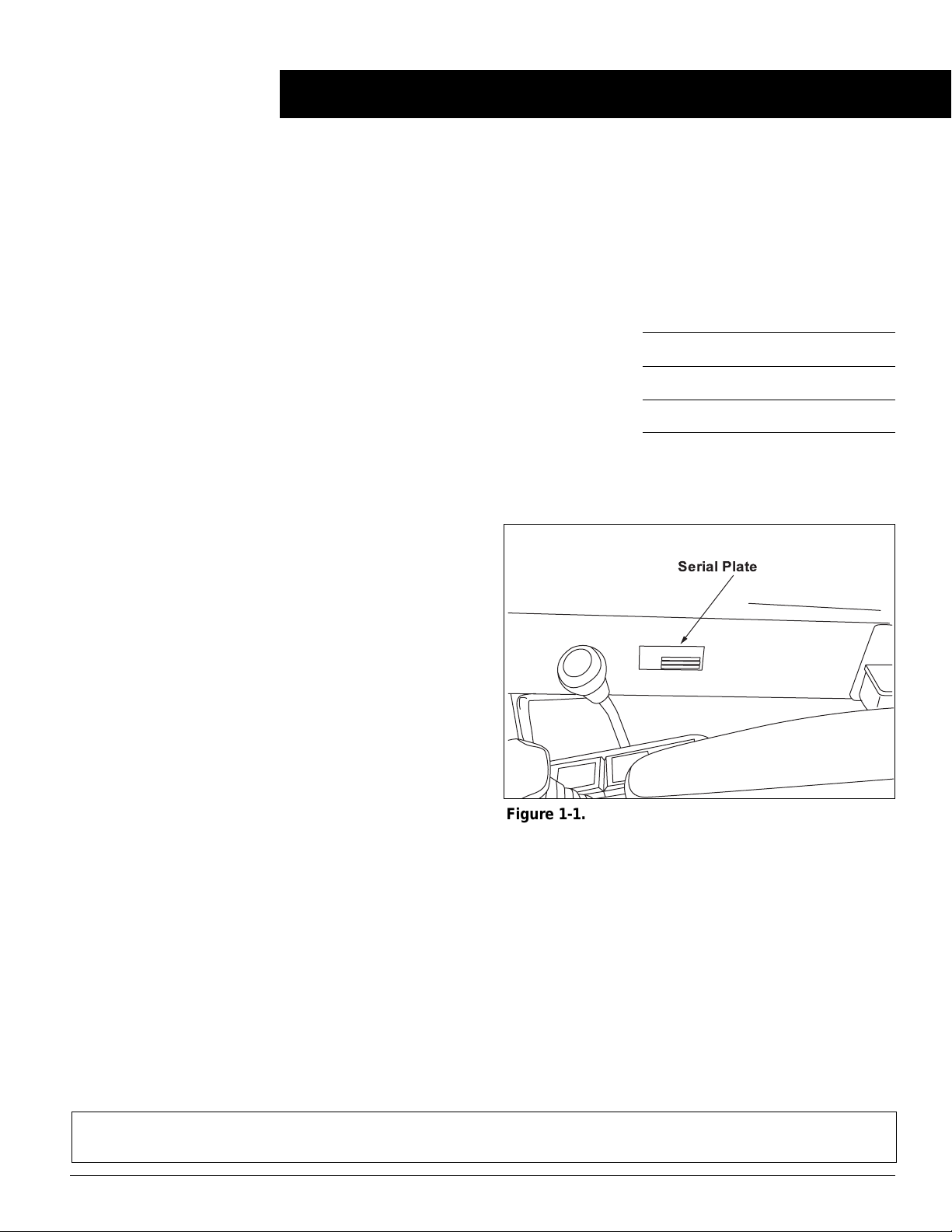
SERIAL NUMBER LOCATION
The serial plate is located on the inside cab wall next to the
throttle lever (Figure 1-1).
GENERAL INFORMATION
The information in this Operator’s Manual was written to
give the owner/operator assistance in preparing, adjusting,
maintaining and servicing the Crawler Excavator. More
importantly, this manual provides an operating plan for safe
and proper use of the machine. Major points of safe operation are detailed in Section 2–Safety Information.
The GEHL®Company asks that you read and understand the
contents of this manual COMPLETELY and become familiar
with your new machine BEFORE attempting to operate it.
Consult your GEHL Dealer to obtain extra manuals, or manuals in other languages.
Throughout this manual, information is provided which is set
in italic type and introduced by the word NOTE or IMPOR-
TANT. Be sure to read carefully and comply with the message. Following this information will improve your operating and maintenance efficiency, help you to avoid breakdown
and damage, and extend the machine’s life.
Do not use this machine for any application or purpose other
than those described in this manual. If the machine is to be
used with special attachments or equipment other than those
approved by Gehl, consult your GEHL Dealer. Any person
making unauthorized modifications is responsible for the
consequences.
The use of this equipment is subject to certain hazards that
cannot be eliminated by mechanical means, but only by exercising intelligence, care and common sense. Such hazards
include, but are not limited to, hillside operation, overloading, instability of the load, poor maintenance and using the
equipment for a purpose for which it is not intended or
designed.
It is essential to have competent and careful operators, who
are not physically or mentally impaired, and who are thoroughly trained in the safe operation of the equipment and the
handling of loads. It is recommended that the operator be
capable of obtaining a valid motor vehicle operator’s license.
GEHLCompany reserves the right to make changes and
improvements in the design and construction of any part
without incurring the obligation to install such changes on
any unit previously delivered.
INTRODUCTION
IMPORTANT!
Keep these instructions with the machine for future reference.
If the machine changes ownership, be sure this manual accompanies the equipment.
NOTE:
All references to Left-hand or Right-hand are determined from sitting in the operator’s seat and facing forward.
Serial Plate
Figure 1-1. Serial Number Location
PRINTED IN U.S.A. 1-1 908147/0999
Page 6
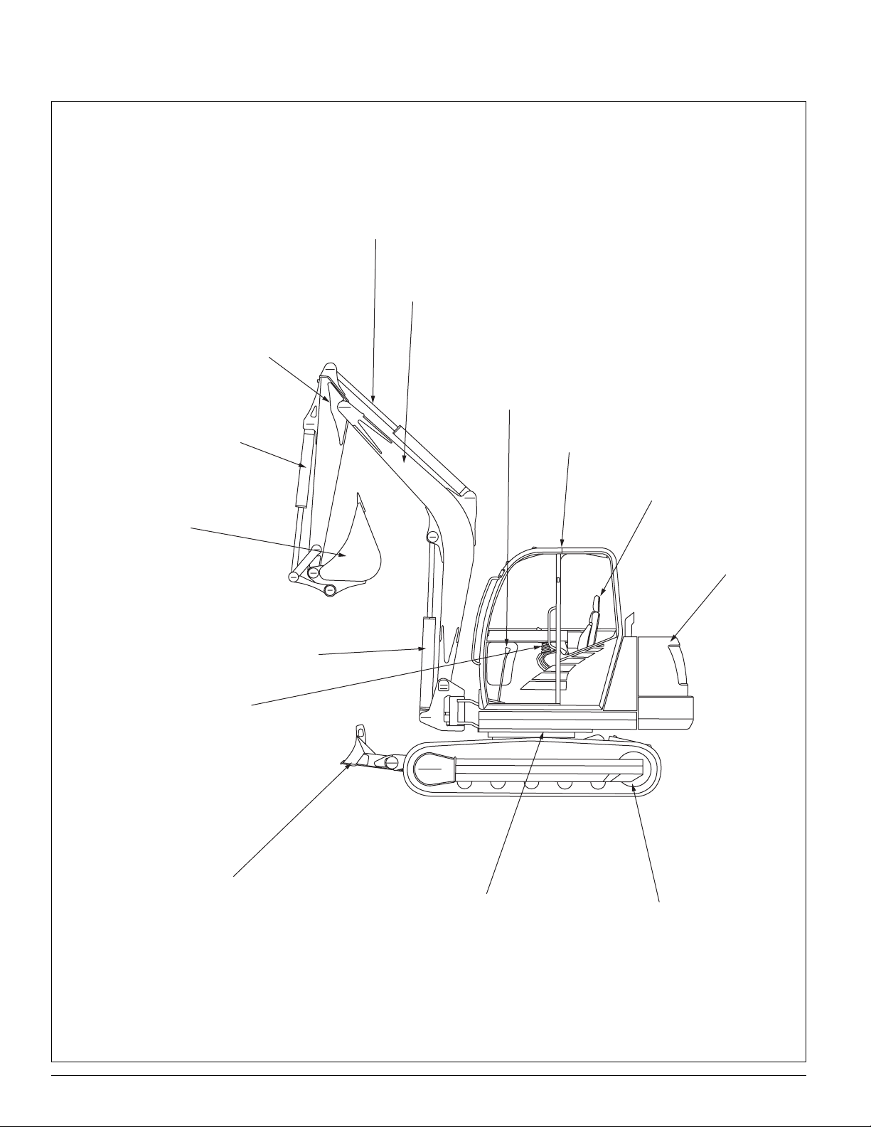
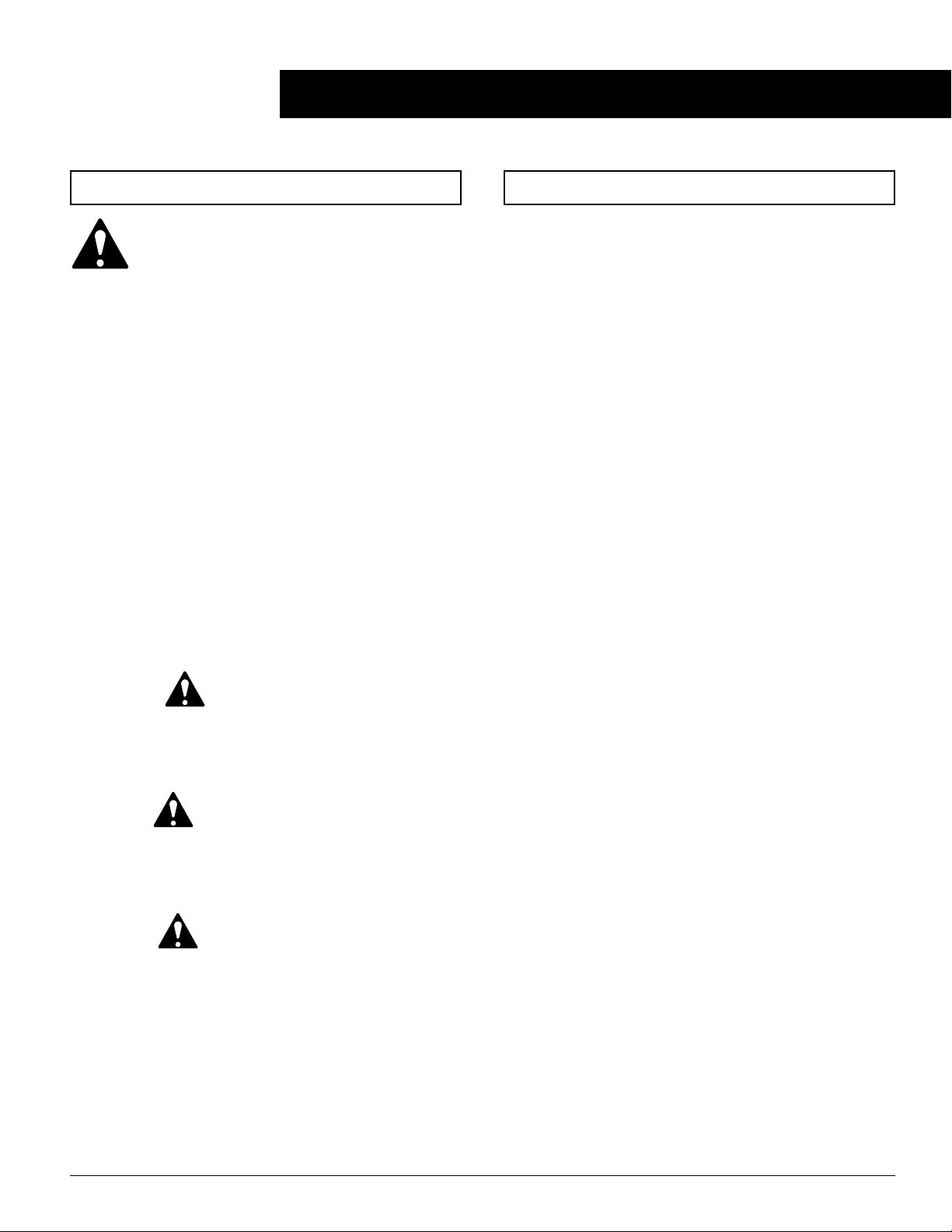
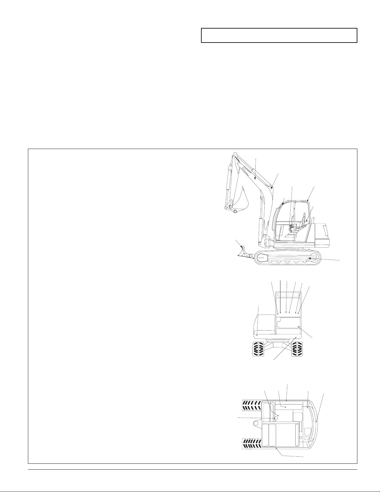
MACHINE IDENTIFICATION
Arm Cylinder
Boom
Arm
Left-hand & Right-hand
Travel Levers
Bucket Cylinder
Bucket
Control Lever
Console
Cab
Operator’s
Seat
Engine Hood
Boom
Cylinder
Dozer
Blade
PRINTED IN U.S.A. 1-2 908147/0999
Superstructure
Track Frame
Page 7

SPECIFICATIONS
GE 802
ENGINE
Make Yanmar
Model 4TNE98-NSR-Diesel
Type 4-Cyl.Water-Cooled
Displacement 202 cu. in. (3318 cc)
Rated Power Output 62 hp (45.6 kW) @ 2300 rpm
Battery 12V (88 Ah)
Fuel Tank 23.75 gal. (90 L)
HYDRAULIC SYSTEM
Pumps Double Axial Piston Pump & One Gear Pump
Flow Rate 21 gpm (80 L/min)
21 gpm (80 L/min)
13 gpm (50 L/min)
Working Pressure 4359 psi (300 bar)
Swing System Pressure 3632 psi (250 bar)
Oil Cooler Standard
Hydraulic Tank 32 gal. (122 L)
UNDER CARRIAGE & SLEWING SYSTEM
Travel Speed-Dual 4 mph (6.4 km/h))
6 mph (9.6 km/h)
Ground Clearance 15 in. (335 mm)
Slew Speed 9.5 rpm
Gradability 30° (= 58%)
Rubber Trac k Width 17.7 in. (450 mm)
Number of Track Rollers 5 each side
Average Ground Pressure 4.27 psi(29.4 kPa)
DOZER BLADE
Width 85 in. (2150 mm)
Height 21 in. (540 mm)
Maximum Lift Above Ground 21 in. (540 mm)
Below Ground 17.7 in. (450 mm)
BUCKET (STANDARD)
Width 129.5 in. (750 mm)
Capacity 9 cu. ft. (0.26m
3
)
NOISE LEVEL
Power Sound 96 dB(A)
Pressure Sound 78 dB(A)
PRINTED IN U.S.A. 1-3 908147/0999
Page 8

GE 802
GENERAL SPECIFICATIONS
Operating Weight w/Cab (SAE) 17,416 lbs. (7900 kg)
Height 101 in. (2570 mm)
Width 84.6 in. (2150 mm)
Length 12.5 ft. (3800 mm)
Max. Digging Depth 173.2 in. (4400 mm)
Max. Digging Height 284.25 in. (7220 mm)
Max. Dump Height 203.9 in. (5180 mm)
Max. Digging Radius 285 in. (7240 mm)
Bucket Dig Force 10,935 lbs. (48.4 kN)
Min.Tail Swing Radius 62.6 in. (1590 mm)
Min. Front Swing Radius 65.7 in. (1670 mm)
Swing Angle-Left 80°
Swing Angle-Right 50°
SPECIFICATIONS (continued)
PRINTED IN U.S.A. 1-4 908147/0999
Page 9
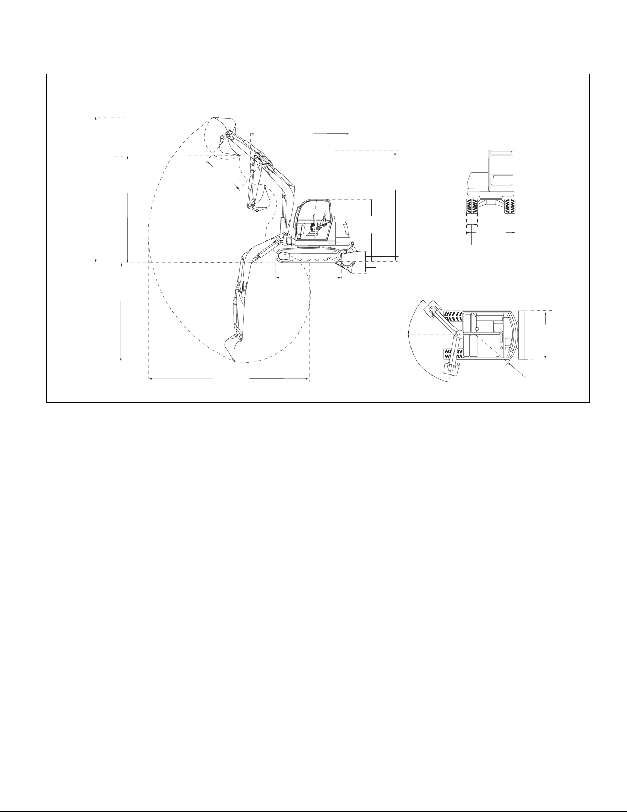
285"
(7240 mm)
284"
(7220 mm)
204"
(5180 mm)
173"
(4400 mm)
109"
(2780 mm)
21.3"
(540 mm)
17.7"
(450 mm)
101"
(2570 mm)
214"
(5440 mm)
15"
(3800 mm)
59"
(1500 mm)
72.8"
(2150 mm)
17.7"
(450 mm)
62.6"
(1590 mm)
72.8"
(2150 mm)
80˚
50˚
Model GE802
PRINTED IN U.S.A. 1-5 908147/0999
Page 10

CHECKLISTS
Pre-Delivery Checklist
Delivery Checklist
The following checklist is an important reminder of valuable
information and inspections which MUST be made before
delivering the machine to the customer. Check off each item
after prescribed action is taken.
✔✔
CHECK THA T:
❏ Unit has NOT been damaged in shipment. Check for
such things as dents and loose or missing parts; correct
or replace components as required.
❏ Battery is securely mounted and NOT cracked. Make
sure cable connections are tight.
❏ Cylinders, hoses and fittings are not damaged, leaking or
loosely connected.
❏ Filters are not damaged, leaking or loosely secured.
❏ Machine is properly lubricated and no grease fittings are
missing or damaged.
❏ Hydraulic system reservoir, engine crankcase and drive
chaincases are filled to their proper levels.
❏ All adjustments are made to comply with settings given
in Section 4–Maintenance of this manual.
❏ All guards, shields and decals are in place and secured.
❏ Model and serial numbers for this unit are recorded in
the space provided on this page and on page 1-1.
IMPORTANT: Start the engine and test run the unit
while checking that all controls operate properly.
✔✔
CHECK THA T:
❏ Drive controls and boom/arm/bucket/swing/pivot
controls operate properly and are not damaged or
binding.
❏ Drive controls are properly adjusted for a correct neutral
position.
❏ The parking and travelling gear brake, along with the
blocking devices, are automatically activated with unit
stationary (no pilot control pressure).
❏ All hydraulic functions are NOT operational with the
left-hand control console in the pivoted rearward
position.
I acknowledge that pre-delivery procedures were performed
on this unit as outlined on this page.
Dealership Name
Dealer Representative Name
Date Checklist Filled Out
Model & Serial Number
The following checklist is an important reminder of valuable
information that MUST be passed on to the customer at the
time of delivery. Check off each item as you explain it to the
customer.
✔✔
EXPLAIN:
❏ The Safety Information and Operation chapters of this
manual, regarding the safe operation of this machine.
❏ The Maintenance and Troubleshooting chapters for
information regarding the proper maintenance of this
machine. Explain that regular lubrication and maintenance is required for continued safe operation and long
machine life.
❏ Give the Operator’s Manual to the customer and instruct
the customer to read and completely understand the contents before operating the unit.
❏ Explain that the customer MUST consult the engine
manual (provided) for related specifications, operating
adjustments and maintenance instructions.
❏ Completely fill out the Owner’s Registration, including
customer’s signature and return it to the Gehl Company.
Customer’s Signature
Date Delivered
Retain for Customer’s Records
PRINTED IN U.S.A. 1-6 908147/0999
Page 11

Cut along dotted line and retain for Dealer’s records.
CHECKLISTS
Pre-Delivery Checklist
Delivery Checklist
The following checklist is an important reminder of valuable
information and inspections which MUST be made before
delivering the machine to the customer. Check off each item
after prescribed action is taken.
✔✔
CHECK THA T:
❏ Unit has NOT been damaged in shipment. Check for
such things as dents and loose or missing parts; correct
or replace components as required.
❏ Battery is securely mounted and NOT cracked. Make
sure cable connections are tight.
❏ Cylinders, hoses and fittings are not damaged, leaking or
loosely connected.
❏ Filters are not damaged, leaking or loosely secured.
❏ Machine is properly lubricated and no grease fittings are
missing or damaged.
❏ Hydraulic system reservoir, engine crankcase and drive
chaincases are filled to their proper levels.
❏ All adjustments are made to comply with settings given
in Section 4–Maintenance of this manual.
❏ All guards, shields and decals are in place and secured.
❏ Model and serial numbers for this unit are recorded in
the space provided on this page and on page 1-1.
IMPORTANT: Start the engine and test run the unit
while checking that all controls operate properly.
✔✔
CHECK THA T:
❏ Drive controls and boom/arm/bucket/swing/pivot
controls operate properly and are not damaged or
binding.
❏ Drive controls are properly adjusted for a correct neutral
position.
❏ The parking and travelling gear brake, along with the
blocking devices, are automatically activated with unit
stationary (no pilot control pressure).
❏ All hydraulic functions are NOT operational with the
left-hand control console in the pivoted rearward
position.
I acknowledge that pre-delivery procedures were performed
on this unit as outlined on this page.
Dealership Name
Dealer Representative Name
Date Checklist Filled Out
Model & Serial Number
The following checklist is an important reminder of valuable
information that MUST be passed on to the customer at the
time of delivery. Check off each item as you explain it to the
customer.
✔✔
EXPLAIN:
❏ The Safety Information and Operation chapters of this
manual, regarding the safe operation of this machine.
❏ The Maintenance and Troubleshooting chapters for
information regarding the proper maintenance of this
machine. Explain that regular lubrication and maintenance is required for continued safe operation and long
machine life.
❏ Give the Operator’s Manual to the customer and instruct
the customer to read and completely understand the contents before operating the unit.
❏ Explain that the customer MUST consult the engine
manual (provided) for related specifications, operating
adjustments and maintenance instructions.
❏ Completely fill out the Owner’s Registration, including
customer’s signature and return it to the Gehl Company.
Customer’s Signature
Date Delivered
Retain for Dealer’s Records
PRINTED IN U.S.A 1-7 0908147/0999
Page 12

This Page Intentionally Blank
PRINTED IN U.S.A. 1-8 908147/0999
Page 13
• Some illustrations in this manual may show doors,
guards and shields open or removed for illustrative purposes only. BE SURE all doors, guards and shields are
in their proper operating positions BEFORE starting the
engine to operate the machine.
• To ensure safe operation, replace damaged or worn-out
parts with genuine Gehl service parts.
• Gehl units are designed and intended to be used ONLY
with Gehl Company attachments or approved referral
attachments. The Gehl Company cannot be responsible
for operator safety if the unit is used with non-approved
attachments.
• The terrain, engine speed, load carried, and abrupt control movements can affect machine stability. If misused,
any of the above factors can cause the machine to tip,
throwing the operator forward or out of the unit,
causing death of serious injury. Therefore, ALWAYS
wear the seatbelt when operating the equipment.
Operate the controls smoothly and gradually at an appropriate engine speed which matches the operating conditions.
• For additional stability when operating on inclines or
ramps, ALWAYS travel with the bucket and blade
towards the top of the incline.
* DO NOT raise or lower a loaded bucket suddenly.
Abrupt movements under load can cause serious instability.
• NEVER attempt to bypass the keyswitch to start the
engine. Use only the jump-starting procedure detailed in
the Maintenance section of this manual.
• NEVER use your hands to search for hydraulic fluid
leaks; use a piece of paper or cardboard. Escaping fluid
under pressure can be invisible and can penetrate the
skin and cause serious injury. If any fluid is injected
into your skin, see a doctor at once. Injected fluid MUST
be surgically removed by a doctor or gangrene may
result.
• Do not operate too close to an excavation or ditch. BE
SURE that the surrounding ground has adequate strength
to support the weight of the machine and the load.
• DO NOT smoke or have any spark producing equipment
in the area while filling the fuel tank or while working
on the fuel or hydraulic systems.
SAFETY INFORMATION
The GEHL®Company, in cooperation with the
Society of Automotive Engineers, has adopted
this Safety Alert Symbol to pinpoint precautions
which, if NOT properly followed, can create a safety hazard. This symbol means ATTENTION! BECOME
ALERT! YOUR SAFETY IS INVOLVED! It stresses an
attitude of “Heads Up For Safety” and can be found
throughout this Operator’s Manual and on the machine.
Before you operate this equipment, read and study the
following safety information. In addition, be sure that
every individual who operates or works with this equipment, whether family member or employee, is familiar
with these safety precautions.
The Gehl Company always considers the operator’s safety
when designing its machinery, and guards exposed moving
parts for the operator’s protection. However, some areas cannot be guarded or shielded in order to assure proper operation.
The following safety words and symbols are used throughout
the manual and on the machine to warn of dangerous situations.
DANGER
DANGER indicates an imminently hazardous
situation which, if not avoided, will result in
death or serious injury.
WARNING
WARNING indicates a potentially hazardous situation which, if not avoided, could result in
death or serious injury.
CAUTION
CAUTION indicates a potentially hazardous situation which, if not avoided, may result in
minor or moderate injury. May also alert
against unsafe practices.
GENERAL SAFETY INFORMATION
Safety Symbols & Terminology Safety Reminders
PRINTED IN U.S.A. 2-1 908147/0999
Page 14

• When driving on or across roads, the machine must be
equipped according to the road/traffic laws, and these
laws must be observed.
• Adapt working speed to local visibility.
• The driving speed must be adapted to the road and
ground conditions.
• Particular attention is required when working on slopes.
Angle of inclination of machine for all directions of travel: for brief operation (2-3 minutes)–maximum of 30°;
for continuous operation–maximum of 25°.
• Unauthorized personnel must not start-up the machine.
• No one but the operator must be on the machine when in
use. PASSENGERS PROHIBITED!
• Use the towing bracket provided for towing the machine.
• The operating area, steps, and grips must be free of oil,
dirt, ice and unsecured objects.
• The proper working condition of the lighting system
must be checked before and while working in darkness.
• Always keep the windshield and windows clean. Poor
visibility can cause accidents.
• Operate the machine from the operator’s seat only. Wear
seatbelt which is provided.
• Control the machine cautiously and gradually until you
are fully familiar with all the controls and handling.
• Pay attention to all movements of machines and
machines in the working area.
• Personnel must not be in the working area. Never operate equipment above people.
• Always wear appropriate protective clothing: hard hat,
work gloves, strong work shoes, reflective clothing.
• Make sure you have sufficient knowledge of the working
area; location of utility lines (water, gas, electric, etc.)
and load bearing capacity of the ground.
• Before working in the area of utility lines, contact the
proper authority to determine the measures required for
safety.
• Never dig underneath the machine. Support walls properly when excavating or working in, or close to, trenches.
• Never drive long distances with the working equipment
fully raised. Lowering the working equipment produces
improved visibility and improved weight distribution.
Safety Reminders (continued)
• Never drive across the incline on sloping ground.
Extreme caution is required when working across an
incline or changing direction.
• Never use the weight of the machine to obtain more
force when excavating. There is a risk overturning.
• Before starting up the machine or setting it in motion,
warn any personnel in the area.
• Attach a clearly visible, legible OUT OF SERVICE sign
when repair and adjustments are being performed on the
machine.
• Unless necessary for servicing the engine, the engine
hood must not be opened while the engine is running.
• Be familiar with the machine safety devices.
• The machine is not to be used to lift equipment or transport personnel.
• The excavator arm is not a ramming tool. Never attempt
to use the working equipment to drive piles or similar
items into the ground, or to flatten the ground.
• Never excavate while the machine is travelling. Never
move the machine to dig. Never slew with lowered
working equipment and never move the machine when
the working equipment is resting on the ground.
The machine has several components that operate at high
temperature under normal operating conditions, primarily the
engine and exhaust systems. Also, the electrical system, if
not properly maintained or is damaged, can arc or produce
sparks. These conditions make it extremely important to
avoid conditions where explosive dust or gasses can be ignited by arcs, sparks or heat.
The machine must be cleaned on a regular basis to avoid the
buildup of flammable debris such as leaves, straw, etc.
Accumulated debris, particularly in the engine compartment,
poses a fire hazard.
The spark arrestor muffler is designed to control the emission
of hot particles from the engine and exhaust system, but the
muffler system still gets hot during operation. For this reason, it is extremely important not to operate the machine in
an area where explosive dust or gasses can contact the hot
exhaust.
• Do not use the machine where explosive gasses or dust
can be ignited by arcs, sparks, hot components or
exhaust gasses.
• The operator cab, engine compartment and engine cooling system must be inspected every day and cleaned if
necessary to remove any flammable debris.
Fire Prevention
PRINTED IN U.S.A. 2-2 908147/0999
Page 15
Mandatory Safety Shutdown Procedure
Before leaving the machine:
1. Lower the working equipment to the ground and support
it securely.
2. Reduce throttle and turn off the engine.
3. Lock out controls by raising left control console.
4. Remove the ignition key and take it with you.
• Check all electrical wiring and connections for damage.
Keep the battery terminals clean and tight. Repair or
replace any damaged parts.
• Check fuel and hydraulic tubes, hoses and fittings for
damage and leakage. Tighten or replace any parts that
show leakage. Always clean fluid spills.
• Always the clean the machine before performing any
welding. Cover rubber hoses, battery and all other flammable parts. Keep a fire extinguisher near the machine
when welding.
• Stop the engine and let it cool before adding fuel.
SAFETY DECAL & STICKER LOCATIONS
1
18
18,19
2
23
7
8
9
10
11
12
14
13,17
53
4
6
15,16
18
14
22
20, 21
29
25, 26
1. WARNING: Danger zone . Keep away! (both sides
of the boom)
2. Direction arrow (left and right on track frames)
3. Hydraulic Oil
4. WARNING–Hydraulic reservoir under pressure
5. Diesel
6. WARNING: Do not open when engine is running
7. Lower boom, raise boom, close bucket, open
bucket (on windshield)
8. Lower dozer blade, raise dozer blade (on windshield)
9. Travel right, forward/reverse (on windshield)
10. Travel left, forward/reverse (on windshield)
11. Bucket arm out, bucket arm in, superstructure left,
superstructure right (on windshield)
12. Environmental symbol (blue angel) (on windshield)
13. Nameplate
14. Warning. TO AVOID INJURY: Read the Operator’s
Manual before using the machine. Be sure all
user’s are instructed on safe use and maintenance. Service the machine per the manual.
Contact dealer (or manufacturer) for information
and service parts.
15. L
WA
96
16. LPA78
17. CE symbol
18. Lifting point for lifting the excavator (left and right
on boom and dozer blade)
19. Tie down point (left and right on dozer blade and
chassis
PRINTED IN U.S.A. 2-3 908147/0999
Page 16
SAFETY DECAL & STICKER LOCATIONS
1
18
18,19
2
23
7
8
9
10
11
12
14
13,17
53
4
6
15,16
18
14
22
20, 21
29
25, 26
20. WARNING: TO AVOID INJURY:
Load and transport unit properly. Inspect job-site
for hazards.
Operate only from operator’s seat. Fasten seatbelt.
Keep people out of DANGER ZONE.
Operate within stability limit of machine. DO NOT
OVERLOAD. Use only approved attachments.
21. WARNING: Mandatory Safety Shutdown
Procedure:
1. Lower all equipment to ground.
2.Reduce throttle; shut off engine.
3.Lock out controls before exiting.
4.Remove key and take it with you.
22. WARNING: TO AVOID INJURY: Always hold handle
when closing front window. When opening window, be sure to lock both sides.
23. WARNING:TO AVOID INJURY OR DEATH: Do not
loosen lubricator more than 2 turns. Do not
loosen parts other than lubricator. Grease is
under high pressure.
24. Lubrication hours
25. Engine cover release latch
26. Hydraulic valve cover release latch
27. Throttle speed
28. Hydraulic breaker
29. Keep hands away from fan blade
PRINTED IN U.S.A. 2-4 908147/0999
Page 17

SAFETY DECALS
WARNING
DANGER ZONE
Keep away!
HYDRAULIC OIL
WARNING
HYDRAULIC RESERVOIR
UNDER PRESSURE
D
DIESEL
WARNING
DO NOT OPEN WHILE
ENGINE IS RUNNING
DOZER BLADE DOWN
DOZER BLADE UP
BOOM DOWN
BUCKET
CLOSED
BUCKET
OPEN
TRAVEL RIGHT
FORWARD
REVERSE
TRAVEL LEFT
FORWARD
REVERSE
ARM OUT
SWING
LEFT
SWING
RIGHT
ARM IN
BOOM LEFT
BOOM RIGHT
WARNING
TO AVOID INJURY:
Read the Operator's Manual before
using this machine.
Be sure all users are instructed on
safe use and maintenance.
Service machine per the Manual.
Contact dealer (or manuafacturer) for
information and service parts.
12 3
456
8
7
910
11
14
BOOM UP
PRINTED IN U.S.A. 2-5 908147/0999
Page 18

SAFETY DECALS (continued)
18 19
WARNING
TO AVOID INJURY:
Load and transport unit properly.
Inspect job-site for hazards.
Operate only from operator's seat.
Fasten seatbelt.
Keep people out of DANGER ZONE.
Operate within stability limit of
machine. DO NOT OVERLOAD.
Use only approved attachments.
1.
2.
3.
4.
1.
2.
3.
4.
20
WARNING
1.
2.
3.
4.
MANDATORY SAFETY
SHUTDOWN PROCEDURE:
1. Lower all equipment to ground.
2. Reduce throttle; shut off engine.
3. Lock out controls before exiting.
4. Remove key and take it with you.
STOP
21
WARNING
AVOID INJURY OR DEATH
Do not loosen lubricator more
than 2 turns
Do not loosen parts other than lubricator.
Grease is under high presure.
23
10
50
24
25 26
27
WARNING
TO AVOID INJURY:
ALWAYS hold handle
when closing front
window.
When opening window be
sure to lock both sides
22
28
A + B
A + T
HYDRAULIC BREAKER
29
PRINTED IN U.S.A. 2-6 908147/0999
Page 19

OPERATION
WARNING
Be sure you are familiar with all safety devices
and controls before operating the machine.
Know how to stop before starting. This GEHL
®
Company machine is designed for use only
with GEHL®Company approved accessories or
referral attachments. The GEHL®Company
cannot be responsible for operator safety if the
unit is used with non-approved attachments.
GENERAL INFORMATION
WARNING
Instructions are necessary before operating
the machine. Read and understand this entire
manual. Follow warnings and instructions for
operation and maintenance. Check for correct
function after adjustments or maintenance.
Failure to follow instructions can result in
injury or death.
Guards & Shields
Whenever possible, guards and shields are used to protect
potentially hazardous areas on the machine. In many places,
decals are also provided to warn of potential hazards and/or
to display special operating procedures (see Safety Decals
Locations in Section 2).
The operator’s seat left-hand console must be raised in order
to exit the cab. In the raised position, the left-hand console
locks out all hydraulic functions of the machine (Figure 3-1).
WARNING
Read and thoroughly understand all safety
decals before operating the machine. DO NOT
operate the machine unless all factory installed
guards and shields are in place.
Armrest Lever
Left-Hand Console
In Raised Position
Figure 3-1. Left-Hand Console Raised
PRINTED IN U.S.A. 3-1 908147/0999
Page 20

OPERATOR CONTROLS
+
-
1
2
3
45 6 7
8
9
10
11
14
15
16
17
18
19
20
21
22
18
20
23
12
13
24
25
26
8
12, 13
1. Auxiliary Hydraulics Pedal
2. Left-Hand Travel Lever w/Foot Pedal
3. Seat Suspension Adjustment Lever
4. Right-Hand Travel Lever w/Foot Pedal
5. Seat Adjustment Lever
6. Footrest
7. Dozer Blade Control Lever w/Foot Pedal
8. Ventilation Controls
9. Cab Light
10. Windshield Washer Reservoir
11. Throttle Lever
12. Hydraulic Valve Cover Latch Lever
13. Engine Cover Latch Lever
14. Right-Hand Control Lever for Boom, Bucket
Cylinder and Horn
15. Ashtray
16. Console Controls (see next page)
17. Radio
18. Stereo Speaker
19. Ignition Key Switch
20. Armrest
21. Storage Shelf
22. Fuse Panel (see next page)
23. Heater
24. Left-Hand Control Lever for Rotating/Slewing
Bucket Arm; Control Button for Boom Swing when
used with Auxiliary Hydraulics Pedal (#1)
25. Armrest Lever (for folding back the armrest which
disables the hydraulic controls)
26. Seat and Console Adjustment Lever
+
-
1
2
3
5
6
7
8
9
10
11
12
4
13
1. Fuel Filler
2. Hydraulic Reservoir
3. Hydraulic Valves
4. Diesel Pump (Option)
5. Hydraulic Oil Filler
6. Hydraulic Oil Filter
7. Hydraulic Oil Sight Gauge
8. Battery
9. Hydraulic Reservoir Drain
10. Fuel T ank Drain
11. Fuel T ank
12. Engine Hood
13. Fire Extinguisher in Tool Box
Inner Cab Layout
Outer Cab Layout
PRINTED IN U.S.A. 3-2 908147/0999
Page 21

-
+
00
0
0
0
0
0
0
HOURS
1
2
3
4
5
6
7
8
9
10
14
15
16
17
11
12
13
1. Fuel Level Gauge
2. Coolant Temperature Indicator
3. Battery V oltage Indicator
4. Engine Oil Pressure Indicator
5. Glow Plug Indicator
6. Engine Air Filter Indicator
7. Hydraulic Oil Level Indicator
8. Low Fuel Indicator
9. Work Lights ON Indicator
10. Hour Meter
11. Heater Control
12. 2-Speed T ravel Switch
13. Light Switch–Cab Front Work Light
14. Ignition Key Switch
15. Light Switch–Boom Work Light
16. Light Switch–Rear Work Light (optional)
Console Controls Layout
1
2
3
4
5
6
7
8
9
10
11
1. Fast Speed (Tilt Switch and Drive Lever) (7.5 Amp)
2. Windshield Wiper and Washer (7.5 Amp)
3. Turn Engine Off (Stop Solenoid) (3.0 Amp)
4. Switch Lighting, Instrument Panel and Lighting (7.5 Amp)
5. Front Work Lights (15 Amp)
6. Heating, Horn (15 Amp)
7. Safety (turning) Light, Free (10 Amp)
8. Cabin Lighting, Socket, Radio (Optional) (10 Amp)
9. Alternator, Starter (10 Amp)
10. Fuel Pump, Free (15 Amp)
11. Changeover Valve, Safety Solenoid Valve (10 Amp)
Fuse Panel
PRINTED IN U.S.A. 3-3 908147/0999
Page 22

OPERATOR CONTROLS (continued)
Left-Hand Lever w/Foot Pedal
Right-Hand Lever w/Foot Pedal
Dozer Lever
w/Foot Pedal
Left-Hand Control
Horn
Right-Hand
Control
Boom Swing
Control (used with
Auxiliary Hydraulic Pedal)
Figure 3-2. Travel Controls; Dozer Control
Figure 3-3. Boom & Bucket Controls
1
1
2
2
3
3
4
4
Left-Hand Control
5
6
7
8
5
6
7
8
Right-Hand Control
Figure 3-4. Boom and Bucket Controls
NOTE: Moving the handles equally in the same direction will result in travelling straight forward or straight
backward.
FORW ARD TRA VEL
Push both levers (Figure 3-2) straight forward, slowly the
same distance.
REVERSE TRA VEL
Pull both levers straight backward, slowly the same distance.
TURNING DURING TRAVEL
Move one lever farther than the other one. To turn left while
moving forward, move the right lever farther forward; to turn
right while moving forward, move the left lever farther forward.
PIVOTING
Move the levers in opposite directions to pivot the machine
on its axis. To pivot left, move the right lever farther forward
while pulling the left lever to the rear; to pivot right, move
the left lever forward while pulling the right lever to the rear.
The boom and bucket are controlled by the right- and lefthand levers on the seat consoles (Figure 3-3).
The superstructure or “house” is slewed (swung) by moving
the left-hand lever left or right (Figure 3-4).
The boom can be slewed (swung) without moving the cab by
pressing the auxiliary hydraulics pedal left or right (Figure 3-
5) while pressing the boom swing switch on the left-hand
control lever.
The boom and bucket are moved using the right-hand control
lever. The button located on the right-hand lever sounds the
horn (Figure 3-3).
The dozer is controlled by the dozer lever (Figure 3-2).
WARNING
Levers and controls should return to neutral
position when released. Be sure the levers and
controls are in the neutral (middle) position
before starting the engine. Operate lever controls gradually and smoothly. Excessive speed
and quick handle movements without regard
for conditions and circumstances is hazardous
and could cause an accident.
Travel Controls
Excavating Controls
PRINTED IN U.S.A. 3-4 908147/0999
Page 23

Figure 3-5. Auxiliary Hydraulics Pedal
-
+
00
0
0
0
0
0
0
HOURS
1
2
3
4
5
6
7
8
9
10
14
15
16
17
11
12
13
Figure 3-6. Console Controls
LEFT-HAND CONTROL LEVER (FIGURE 3-3)
1. Move the left-hand lever forward to move bucket arm
away from the machine.
2. Move the left-hand lever to the rear to move the arm
towards the machine.
3. Move the left-hand lever to the left to slew superstructure to the left.
4. Move the left-hand lever to the right to slew superstructure to the right.
RIGHT-HAND CONTROL LEVER (FIGURE 3-4)
5. Move the right-hand lever forward to lower the boom.
6. Move the right-hand lever to the rear to raise the boom.
7. Move the right-hand lever to the left to close the bucket
(bucket moves up and toward the boom).
8. Move the right-hand lever to the right to open the bucket
(bucket moves down and away from the boom).
AUXILIARY HYDRAULICS PEDAL (FIGURE 3-5)
Lift the protective shield, then depress the pedal left or right
while depressing the switch located on top of the left-hand
control lever to slew only the bucket (superstructure will
remain stationary).
DOZER BLADE
The dozer blade is raised and lowered by the dozer lever
w/foot pedal (Figure 3-2). Push the lever forward to lower
the blade; pull the lever to the rear to raise the dozer blade.
1. FUEL LEVEL GAUGE
The fuel gauge shows the level of fuel in the tank.
2. COOLANT TEMPERATURE INDICAT OR
Indicator light comes on when coolant temperature is too
high.
3. BA TTER Y V OL TAGE INDICA T OR
Indicator light comes on when battery voltage is too low.
4. ENGINE OIL PRESSURE INDICATOR
During normal operation, this indicator light should remain
off. The indicator will light if the engine oil pressure drops
too low. If this occurs, shut off the engine IMMEDIATELY
and determine the cause of the pressure drop.
5. GLOW PLUG INDICATOR
Indicator light comes on when the ignition key is turned on.
Indicator will go out when glow plugs have heated sufficiently to start the engine.
6. ENGINE AIR FILTER INDICATOR
Indicator light comes on when engine air filter is too dirty.
Console Controls (Figure 3-6)
7. HYDRAULIC OIL LEVEL INDICATOR
Indicator light comes on when hydraulic oil level is too low.
Shut off engine and add oil.
8. LOW FUEL INDICATOR
Indicator light comes on when fuel level is too low.
9.WORK LIGHTS INDICATOR
Indicator light comes on when work lights are turned on.
Must use with Boom Swing Switch on Left-Hand Control
PRINTED IN U.S.A. 3-5 908147/0999
Page 24

OPERATOR CONTROLS (continued)
10. HOUR METER
Indicates total operating hours of the machine. Use the hour
meter to log maintenance time in the log located in
Section 4–Maintenance.
11. HEATER CONTROL SWITCH
Turns on the cab heater and controls the fan speed.
12. 2-SPEED TRAVEL CONTROL SWITCH
Turn the switch on to engage a higher travel speed. With
switch on, machine can only move straight forward or rearward. It will not steer to either side.
13. CAB FRONT WORKING LIGHT SWITCH
Turns the working light on the front of the cab on and off.
The switch has two positions; the first position operates the
low beam; the second position operates the high beam.
14. IGNITION KEYSWITCH
With the key in the OFF (vertical) position, power from the
battery is disconnected to the controls and console. This is
the only position that the key can be inserted or removed
from the switch.
With the key turned one position clockwise (RUN) from the
vertical position, power from the battery is supplied to all
controls and electrical circuits.
With the key turned fully clockwise (START) and held in
position, the electric starter energizes and starts the engine
when the glow plug indicator goes out. Release the key after
the engine starts.
NOTE:
The key must always be returned to the OFF
position between attempts to start the engine in order to
activate the glow plug system.
15. BOOM WORKING LIGHT SWITCH
Turns the boom working light on and off.
16. REAR WORKING LIGHT SWITCH (Optional)
Turns the optional rear working light on and off.
17.WINDSHIELD WIPER SWITCH
Pushing the switch to the first position turns the windshield
wiper on. Pushing and holding the switch in the second position activates the washer fluid pump.
NOTE:
The operator’s seat left-hand console must be
raised in order to exit the cab. In the raised position,
the left-hand console locks out all hydraulic functions of
the machine (Figure 3-7).
Console Controls (continued) (Figure 3-6)
Operator’s Seat Adjustment Controls
Armrest Lever
Left-Hand Console
In Raised Position
Figure 3-7. Operator’s Seat with Left-Hand
Console Raised
Seat/Console
Adjustment Lever
Seat Suspension
Adjustment Lever
Seat Adjustment Lever
Figure 3-8. Operator’s Seat Adjustment Controls
SEAT SUSPENSION ADJUSTMENT LEVER
Turn the lever (Figure 3-8) to adjust the seat suspension for
the operator’s weight. An indicator on the front of the seat
base shows the weight adjustment.
SEAT/CONSOLE ADJUSTMENT LEVER
The seat/console lever (Figure 3-8) allows the operator to
move the seat and console forward or rearward as a unit.
SEAT ADJUSTMENT LEVER
The seat adjustment lever (Figure 3-8) allows the operator to
move the seat only (without console) forward or rearward.
PRINTED IN U.S.A. 3-6 908147/0999
Page 25

Ventilation
Cab Latches
Handle
Latch
Figure 3-9.Windshield
Latch
Vents
Figure 3-10. Side Window
WINDSHIELD
The windshield can be opened for ventilation. Turn the latch
(Figure 3-9) located at the upper corners of the windshield.
Grasp the handles and pull the windshield up until latches
lock in position.
To close the windshield, turn the latches then lower the windshield until the latches lock in position.
SIDE WINDOW
The side window can be opened for ventilation. Squeeze the
latch (Figure 3-10) located on the window, then slide window
to desired position and release latch.
VENTS
There are two side vents located underneath the side window
(Figure 3-10. Open the slats for better ventilation.
CAB DOOR LATCH
When fully opened, the cab door will lock in position to the
side of the cab. To release the latch, pull the black knob
located on the right side of the door jamb.
ENGINE AND HYDRAULIC VALVE COVER LATCHES
The engine cover and hydraulic valve cover latches are located next to the operator’s seat, on the right-hand side.
To unlock a cover, pull the respective latch handle. The
cover can then be opened.
WARNING
When opening windshield, be sure to lock both
latches. When closing windshield, keep hands
on handle and away from path of window.
PRINTED IN U.S.A. 3-7 908147/0999
Page 26

MACHINE OPERATION
Checklist Before Operation
Check the following items before each day of operation:
• Seat belt and mounting hardware.
• Decals. Replace as required.
• Air cleaner and intake hoses.
• Engine coolant level and system for leaks.
• Clean engine area of any flammable materials.
• Check engine oil level and fill if required.
• Check hydraulic system for leaks and check hydraulic
fluid level.
• Check all pivot points for proper operation.
• Check track tension.
• Check for broken and loose parts, and repair.
• Check fuel tank.
IMPORTANT: Never operate machine until fuel tank
is completely empty. If this occurs, the fuel system
will have to be bled of air. Always fill tank after use.
Starting/Stopping the Engine
WARNING
Instructions are necessary before operating or
servicing the machine. Read this entire manual and all decals on the machine. Follow all
warnings and instructions. Failure to follow all
instructions can cause injury or death.
WARNING
See the list of recommended lubricants in
Section 4–Maintenance
for proper grade of
engine oil and hydraulic oil. Only use oils of
specified on the list or serious injury or death
could occur.
SAFETY DEVICES
When the machine is stationary (no pilot control pressure),
the parking and travelling gear brake are automatically activated.
All hydraulic functions are inoperable with the operator’s
seat left-hand console in the raised position.
The brakes are not released and hydraulic functions activated
until a travel lever or control lever is operated.
NORMAL STARTING/STOPPING PROCEDURE
1. Adjust the operator’s seat to desired settings.
2. Be sure all levers and controls are in neutral positions.
3. Insert ignition key into switch and turn clockwise to the
first position. Indicators for oil pressure and battery
voltage will light.
4. Turn the key fully clockwise and hold in position until
glow plug indicator goes out (approximately 10 seconds
when engine is cold).
5. When engine starts, release the key.
6. Allow engine to warm-up for approximately 5 minutes
to warm the hydraulic fluid.
7. Turn the key fully counterclockwise to turn the engine
off.
IMPORTANT: Do not engage the starter motor for
longer than 10 seconds at each starting attempt. If
the engine does not start, wait 30 seconds, turn the
key fully off, then attempt to start the engine again.
WARNING
Do not use ether with glow plugs (preheat) systems. Explosion can result which can cause
injury or damage.
WARNING
When an engine is running in an enclosed
area, fresh air must be added to avoid concentration of exhaust fumes. If the machine is stationary, vent the exhaust outside. Exhaust
fumes contain odorless, invisible gases which
can kill without warning.
Engines have hot parts and hot exhaust gas.
Keep flammable materials away from engine.
Do not use machine in atmosphere containing
explosive gas.
PRINTED IN U.S.A. 3-8 908147/0999
Page 27

Starting/Stopping the Engine (continued)
Mandatory Safety Shutdown Procedure
COLD WEATHER STARTING PROCEDURE
1. Install an engine heater.
2. Be sure engine oil is correct type and viscosity for the
ambient temperature.
3. Be sure battery is fully charged.
4. Push the throttle lever (Figure 3-11) fully forward.
5. Follow all steps under Normal Starting Procedure on
previous page.
6. As the engine warms up and engine speed increases,
move the throttle lever to the idling position.
NEW MACHINE BREAK-IN PROCEDURE
A new machine requires careful operation during the first 100
hours to properly break-in various parts. If the machine is
subjected to hard use during the break-in period, the performance and service life will be reduced.
Perform the following when operating a new machine:
• After starting, let the engine idle for 5 minutes so all the
components can warm-up.
• Avoid operation with heavy loads or at high speeds.
• Avoid sudden starting and stopping or abrupt motions.
1. Set the travel speed using the travel speed switch on the
console:
Slow Speed Maximum = 4 mph (6.4 km/h)
Fast Speed Maximum = 6 mph (9.6 km/h)
NOTE:
If the travel speed switch on the console
(Figure 3-12) is in the fast speed position, machine will
not turn right or left. It will only go straight forward or
rearward.
2. Push or pull the travel levers w/foot pedals to move the
machine (Figure 3-12).
Push both levers forward to move forward.
Pull both levers rearward to travel in reverse.
NOTE:
If the superstructure has been rotated 180°
(dozer blade at the rear), travel levers will work in the
opposite manner.Pushing levers forward will cause the
machine to travel in reverse and pulling levers to the
rear will move the machine forward.
Throttle Lever
Figure 3-11.Throttle Lever
Left-Hand Lever w/Foot Pedal
Right-Hand Lever w/Foot Pedal
Travel Speed
Switch
Figure 3-12.Travel Levers & Speed Switch
IMPORTANT: Indicator lamps must go out when
engine starts. If they do not, turn off the engine
IMMEDIATELY until cause has been determined and
fixed.
Before leaving the machine:
1. Lower the working equipment to the ground and support
it securely.
2. Reduce throttle and turn off the engine.
3. Lock out controls by raising left control console.
4. Remove the ignition key and take it with you.
Moving the Excavator
3. To turn left, pull the left-hand travel lever back and push
the right-hand lever forward.
To turn right, pull the right-hand lever back and push the
left-hand lever forward.
4. To stop travelling, return levers to neutral (middle) position.
NOTE:
When released, levers and controls return to the
neutral position automatically.
PRINTED IN U.S.A. 3-9 908147/0999
Page 28

Operating on Slopes
EARTHMOVING
Operating on a slope is inherently dangerous. It is recommended to level the work area as shown in Figure 3-13. If
this is not possible, use the following guidelines.
• When going down a slope, control the speed with the
travelling levers and the the throttle lever.
• When going down grades that exceed 15°, put the
machine in the position shown in Figure 3-14. Run the
engine slowly.
• Operate as slowly as possible and avoid sudden changes
in direction.
• Avoid travelling over objects such as rocks, trees,
stumps, etc.
• Stop the machine travel before moving the bucket or
dozer controls.
• Slow down the work cycle. Take your time.
• Avoid working with the tracks positioned across the
slope. Position the machine with the blade downhill and
lowered.
• Avoid swinging or extending the bucket farther than necessary in a downhill direction. When you must swing
the bucket downhill, keep the boom low and skid the
bucket along the ground.
• When working with the bucket on the uphill side, keep
the bucket as close to the ground as possible. Unload far
enough away from the trench or hole to prevent the possibility of a cave-in.
• Mud and water should be removed from the machine
before parking. If possible, park the machine on boards
or concrete to prevent the track or undercarriage from
freezing to the ground and preventing machine movement.
WARNING
Do not travel up or across a slope steeper than
15°. Do not travel down a slope steeper than
25°. Keep boom centered while travelling.
Keep attachments as low as possible when
travelling on slopes or rough terrain.
Figure 3-13. Levelling the Work Site on a Slope
12"
Maximum
(305 m
m)
25 Maximum
Figure 3-14.Travelling on a Slope Exceeding 15°
Operating in Water
• Do not operate or immerse the machine in water higher
than the tracks.
• Properly grease the machine if it has been operated or
immersed in water for a period of time.
IMPORTANT: Never operate machine until fuel tank
is completely empty. If this occurs, the fuel system
will have to be bled of air. Always fill tank after use.
PRINTED IN U.S.A. 3-10 908147/0999
Page 29

The excavator boom can be slewed 45° to the right and 80°
to the left from the basic front position. This allows excavation of trenches along walls, fences, etc.
OPTIMAL STABILITY WHEN DIGGING
• Use the dozer blade to support the excavator on the
ground.
• Never dig under the machine. Support the walls properly when excavating or working close to trenches.
• To obtain maximum digging performance, avoid fully
extending the excavator arm. Excavate using long, flat
pulling movements of the arm (Figure 3-15).
WARNING
Always ensure adequate stability when working with the machine. Particularly when working with equipment slewed to the side.
Changing the working equipment alters the
stability (weight) of the machine.
WARNING
Always ensure adequate stability when working near trenches. Be aware of conditions that
could cause the earth to collapse resulting in
risk of injury or death.
Figure 3-15. Proper Excavating
Excavator Boom Slewing
Digging
Grading
• The boom must be fully raised and the bucket tilted in
(up) when grading.
• When grading, the material may be pushed away to the
front or the side.
• Raise the dozer blade slightly if excessive resistance
occurs.
PRINTED IN U.S.A. 3-11 908147/0999
Page 30

Loading Machine for Transport
TRANSPORTING
• Use only transport machines that are in proper working
order and are approved for use on public roads.
• When using ramps to load machine onto the transport
machine:
- Do not exceed an incline of 18°.
- Ramp width must be at least 1½ times the
width of the track.
- Clean dirt, mud, ice and snow from the
ramps and tracks.
• Use metal loading ramps with a slip-resistant surface.
NOTE:
The ends of the ramps should be beveled to
prevent damage to the rubber tracks (Figure 3-16).
• Attach ramps securely to the transport machine to prevent them from slipping off during loading.
• Load the machine on solid, even ground.
• When loading, apply the transport machine parking
brake and chock the wheels.
• Determine the direction of the track movement (blade
facing forward) before moving the machine onto the
ramps.
• After the machine is on the transport machine, lower the
dozer blade and the bucket onto the loading surface
(Figure 3-16). Turn off the engine.
• Lock the cab.
• Place chocks under machine tracks and secure machine
to prevent slipping, overturning and moving on the transport machine.
• Use the points on the excavator indicated by decals for
tie down.
Beveled Ramps
Figure 3-16.Transporting the Machine
Lifting
Point
Lifting
Point
Spreader
Bar
Figure 3-17. Machine Lifting Points
Lifting Machine
• Secure the lifting fixture sling to the lifting points on the
machine (Figure 3-17).
• Install spreader bar above the cab to prevent lifting fixture from rubbing on the machine.
• Do not exceed rated load capacity.
WARNING
Use lifting device with sufficient capacity for
the weight of the machine plus any attachments.
Maintain center of gravity and balance when
lifting.
Do not swing boom or cab.
Never lift machine with operator aboard.
PRINTED IN U.S.A. 3-12 908147/0999
Page 31

• Care and servicing have a significant influence on the
readiness for operation and service life of the machine.
• For additional servicing work regarding the engine, see
the engine manual provided with the machine.
• Use of lubricants which do not correspond to the manufacturer’s recommendations may invalidate warranty
claims.
• More frequent servicing, other than the recommended
intervals, may be required under extreme operating conditions.
• Always dispose of waste lubricating oils and hydraulic
fluids according to local regulations or take to a recycling center for proper disposal. DO NOT pour fluids
onto the ground or down a drain.
MAINTENANCE
WARNING
Be sure you are familiar with all safety devices
and controls before operating or servicing the
machine. Know how to stop before starting.
This Gehl®Company machine is designed for
use only with Gehl®Company approved accessories or referral attachments. The Gehl
®
Company cannot be responsible for operator
safety if the unit is used with non-approved
attachments.
GENERAL INFORMATION
WARNING
Instructions are necessary before operating
and servicing the machine. Read and understand this entire manual. Follow warnings and
instructions for operation and maintenance.
Check for correct function after adjustments or
maintenance. Failure to follow instructions can
result in injury or death.
Care and Servicing
• Never service the machine without reading the
applicable instructions.
• Always lower bucket and dozer blade to the
ground before performing any maintenance.
• Use correct procedures to lift and support the
machine. Always lift the blade fully before
installing jackstands.
• Cleaning and maintenance are required daily.
• Keep engine cover and valve cover closed
except for service. Close and latch covers
before operating the machine.
• Be sure to have area properly ventilated when
grinding or welding parts. Wear dust mask.
• Vent exhaust to outside when engine must be
run for service. Exhaust system must be tightly
sealed. Exhaust fumes can kill without warning.
• Never modify equipment or add attachments
not approved by Gehl Company.
• Stop engine and let cool, then clean engine of
any flammable materials before checking fluid
levels.
WARNING
Read and thoroughly understand all safety
decals before operating the machine. DO NOT
operate the machine unless all factory installed
guards and shields are in place.
WARNING
Hydraulic reservoir is under pressure. Avoid
contact with leaking hydraulic fluid or diesel
fuel under pressure. It can penetrate the skin
or eyes.
CALIFORNIA PROPOSITION
65 W ARNING
Diesel engine exhaust and some of its constituents are known to the State of California to
cause cancer, birth defects and other reproductive harm.
Maintenance Safety
PRINTED IN U.S.A. 4-1 908147/0999
Page 32

GENERAL INFORMATION (continued)
Maintenance Safety (continued)
• Never service or adjust machine with the engine
running unless service procedure calls for the
engine to be running.
• Avoid contact with leaking hydraulic fluid or
diesel fuel under pressure. It can penetrate the
skin or eyes. NEVER use your hands to search
for hydraulic fluid leaks; use a piece of paper or
cardboard. Escaping fluid under pressure can
be invisible and can penetrate the skin and
cause serious injury. If any fluid is injected into
your skin, see a doctor at once. Injected fluid
MUST be surgically removed by a doctor or
gangrene may result.
• The operating pressure settings of the hydraulic
system should only be set by trained, qualified
personnel. If malfunctions are caused by unauthorized alteration of operating pressure settings, all warranty responsibilities on the part of
the manufacturer are automatically invalidated.
• Never fill fuel tank with engine running, while
smoking or when near open flame.
• Keep body, jewelry and clothing away from moving parts, electrical contacts, hot parts and
exhaust.
• Wear eye protection when servicing the
machine.
• Lead acid batteries produce flammable and
explosive gas. Keep arcs, sparks, flames and
lighted tobacco away from batteries.
• Batteries contain acid which burns eyes and
skin on contact. Wear protective clothing. If
acid contacts body, flush well with water. For
eye contact, flush well with water and get immediate medical attention.
PRINTED IN U.S.A. 4-2 908147/0999
Page 33

Engine
MAINTENANCE SCHEDULE
IMPORTANT: Maintenance work must be done at regular intervals. Failure to perform scheduled maintenance
work will result in excessive wear and early machine failures.The following service schedule is a recommended guide for servicing the machine.
Service Activity Daily Weekly Every Every Every Every Annually
50 125-250 500 1000
Hours Hours Hours Hours
Check air filter ✔✔✔
Check engine oil level ✔
Check fuel level ✔
Check for leakage ✔
Perform visual check ✔
Check coolant level ✔
Check engine mounting bolts ✔
Check V-belt condition and tension ✔
Clean radiator fins ✔
Check fuel filter ✔
Check exhaust system ✔
Change engine oil and filter ✔* ✔✔
Change fuel filter ✔✔
Check engine speed regulation ✔
Check valve clearance ✔
Check cooling system and hoses ✔
Check electrical connections ✔
Check pre-glow system ✔
Check coolant thermostat ✔
Check alternator & starter ✔
Clean fuel tank ✔
Check water pump ✔
* First change only.
PRINTED IN U.S.A. 4-3 908147/0999
Page 34

Service Activity Daily Weekly Every Every Every Every Annually
50 125-250 500 1000
Hours Hours Hours Hours
Check track after work shift ✔
Check track tension ✔
Check bearing play of track
rollers, track carrier rollers &
front idlers. ✔
Hydraulic System
Service Activity Daily Weekly Every Every Every Every Annually
50 125-250 500 1000
Hours Hours Hours Hours
Check hydraulic oil level ✔
Check system for leakage ✔
Check hydraulic pump bolts ✔
Clean cooler fins ✔
Change filter ✔*
Change hydraulic oil ✔* ✔✔
Check filter ✔
Check hydraulic oil ✔✔✔
Check primary & secondary
pressure limiting valves ✔
Check breather filter &
filling strainer ✔
Electrical System
Service Activity Daily Weekly Every Every Every Every Annually
50 125-250 500 1000
Hours Hours Hours Hours
Check indicator lights ✔
Check system function ✔
Check connections ✔
MAINTENANCE SCHEDULE (continued)
* First change only.
Travelling Gear
PRINTED IN U.S.A. 4-4 908147/0999
Page 35

Service Activity Daily Weekly Every Every Every Every Annually
50 125-250 500 1000
Hours Hours Hours Hours
Check fan ✔
Check function ✔
Check heating circuit
for leaks ✔
Check seals ✔
* First change only.
Travelling Gear Unit
Service Activity Daily Weekly Every Every Every Every Annually
50 125-250 500 1000
Hours Hours Hours Hours
Check for leakage ✔
Change final drive gear oil ✔* ✔✔
Slewing Gear Ring
Service Activity Daily Weekly Every Every Every Every Annually
50 125-250 500 1000
Hours Hours Hours Hours
Change gear ring ✔
Check bearing system ✔✔
Cab Heating System
Service Activity Daily Weekly Every Every Every Every Annually
50 125-250 500 1000
Hours Hours Hours Hours
Lubricate all points ✔
Check bucket teeth for wear ✔
Check pin fastening ✔
Check hydraulic line connections ✔
Check piston rods ✔
Check hydraulic cylinder
under load ✔
Check bearing play ✔
Bucket, Boom & Dozer Blade
PRINTED IN U.S.A. 4-5 908147/0999
Page 36

Service Activity Daily Weekly Every Every Every Every Annually
50 125-250 500 1000
Hours Hours Hours Hours
Check hydraulic system ✔
Check bolts ✔
Check lights ✔
Check windshield wiper system ✔
Check for leaks ✔
General
Lubrication Points
MAINTENANCE SCHEDULE (continued)
LUBRICATION
W
W
W
W
Superstructure bearing system (W)
Green Caps–lubricate weekly (points marked with a “W”)
Blue Caps–lubricate daily
Figure 4-1. Lubrication Points
PRINTED IN U.S.A. 4-6 908147/0999
Page 37

Checking Engine Oil Level
ENGINE
Figure 4-2. Engine Oil Dipstick
IMPORTANT: See the lubricant list for engine oil
grade. Only use engine oil specified, or of equivalent quality and grade, or damage to the engine
could occur.
The machine must be on a level surface and the engine
turned off.
1. Run the engine until it is at operating temperature, then
turn the engine off.
2. Pull the engine cover latch lever (located next the right
side of the operator’s seat) and raise the engine cover.
3. Check the engine oil level using the dipstick located on
rear of the engine (Figure 4-2).
4. Add oil if required.
NOTE:
The marks on the dipstick indicate the minimum
and maximum oil levels.
Dipstick
NOTE:
Be sure to read the engine manual supplied with
this machine.
Recommended Lubricants
ENGINE OIL
A diesel engine oil conforming to SAE grade 10W 30 or
15W 40, and API classification CD (or higher, e.g., CH-4),
such as BP Vanellus MG 15W 40, BP Vanellus C-Extra
10W 30, or Chevron Delo 400 15W 40
HYDRAULIC OIL
A hydraulic oil with anti-wear,anti-foam, and anti-oxidation
additives that conforms to ISO Viscosity Grade 46, such as,
Mobil DTE 15M, Amoco Rykon 46, or BP Energol
HLP-HD 46.
SLEWING RING
A heavy-duty lithium complex grease with 3% molybdenumdisulfide, such as Chevron RPM Heavy Duty Grease No.
2, Mobilgrease Moly 52, or BP Energrease Moly EP2.
TRAVELLING GEAR UNIT
An EP grade gear oil that conforms to API GL 5, such as
Chevron Delo Gear 80W 90 or BP Transgear 80W 90
SLEWING GEAR UNIT
An EP grade gear oil that conforms to API GL 5, such as
Chevron Delo Gear 80W 90 or BP Transgear 80W 90
EXCAVATOR ARM
A heavy-duty lithium complex grease with 3% molybdenumdisulfide, such as Chevron RPM Heavy Duty Grease No.
2, Mobilgrease Moly 52, or BP Energrease Moly EP2.
ALL LUBRICATION POINTS
A heavy-duty lithium complex grease with 3% molybdenumdisulfide, such as Chevron RPM Heavy Duty Grease No.
2, Mobilgrease Moly 52, or BP Energrease Moly EP2.
RANGES OF APPLICATIONS
From -13°F to +104°F (-25°C to +40°C)
outside temperature
NOTE:
All listed greases are suitable for
-13°F to +104°F (-25°C to +40°C).
PRINTED IN U.S.A. 4-7 908147/0999
Page 38

Bolt
Changing Engine Oil & Filter
ENGINE (continued)
1. Place the machine on a level surface. Run the engine
until it is at operating temperature, then turn the engine
off.
2. Pull the engine cover latch lever (located next the right
side of the operator’s seat) and raise the engine cover.
3. Remove the drain plug from the oil pan underneath the
engine and allow oil to drain into a container.
4. Remove the oil filter using a filter wrench.
5. Clean the filter housing surface. Put a film of clean oil
on the filter gasket. Install the new filter with gasket and
hand tighten.
6. Reinstall the drain plug.
7. Remove the oil fill cap from the engine (Figure 4-3).
Pour in new oil. Crankcase capacity is 6.1 qts. (5.7 L).
Reinstall oil fill cap.
8. Start the engine and let it run for several minutes. Stop
the engine and check for leaks at the oil filter and oil
drain plug.
9. Check the oil level again and add oil if necessary.
1. The air cleaner is located under the side cover. Pull the
side cover latch lever (located on the right-side of the
operator’s seat) and raise the side cover.
2. Turn the air cleaner cover bolt (Figure 4-4) to remove
the air cleaner cover and gasket.
3. Remove the wingnut (Figure 4-5) and remove air cleaner
element.
4. Clean air cleaner element with compressed air 30 psi
(200 kPa) (Figure 4-5).
5. Reinstall air cleaner element, wingnut, gasket, and air
cleaner cover. Tighten cover bolt.
6. Close valve cover.
IMPORTANT: Do not knock the element against
solid object to remove dust. The element may
become distorted and damaged.
Do not operate engine without the air cleaner element installed or damage to the engine could occur.
Figure 4-3. Engine Oil Fill and Filter
Oil Filter
Oil Fill
Figure 4-4. Engine Air Filter
Figure 4-5. Servicing Engine Air Filter
Air Cleaner Service
Air Cleaner Cover
Gasket
Compressed Air
Wingnut
PRINTED IN U.S.A. 4-8 908147/0999
Page 39

Fuel
Filter
Valve
Fuel Filter
Plastic
Housing
Water Separator
Injection Pump
Priming Lever
Figure 4-7. Fuel Filter
Figure 4-8. Bleeding Air from Fuel System
A
B
E
Fuel Filter
Injection
Pump
Water
Separator
C
D
The fuel level in the tank is indicated by the fuel gauge on
the console (Figure 4-6).
NOTE:
When the fuel level reaches 2.5 gal.(2.3 L) the
low fuel indicator light (Figure 4-6) will come on to alert
the operator.
To fill the tank, remove the fuel filler cover located on the
right-side of the machine. Fill using diesel fuel with a cetane
rating of over 45. Re-install fuel cap.
IMPORTANT: Never operate machine until fuel tank
is completely empty. If this occurs, the fuel system
will have to be bled of air. Always fill tank after use.
Unscrew the clear plastic housing (Figure 4-9) to change the
filter element and clean dirt from the housing. Clean around
the filter housing. Put oil on the seal of the new filter element. Install the fuel filter and hand tighten.
The fuel system must be purged of air after changing the fuel
filter, or if the fuel tank has been run dry.
1. Turn the fuel filter valve (Figure 4-7) to the open position (vertical).
2. While operating the priming lever on the fuel injector
pump, loosen the air bleeding screw (A, Figure 4-8) on
the fuel filter. When fuel starts flowing from the bleeder
valve (A) without any air, tighten the bleeder screw (A).
3. Repeat step 2 for bleeder screws B, C, D and E
(Figure 4-8).
Filling the Fuel Tank
Fuel Filter
Purging Air from the Fuel System
FUEL SYSTEM
Figure 4-6. Fuel Gauge and Low Fuel Indicator
-
+
00
0
0
0
0
0
0
HOURS
Fuel Gauge
Low Fuel
Indicator Light
WARNING
Stop and cool the engine before adding fuel.
NO SMOKING! Failure to obey warnings can
cause an explosion or fire.
WARNING
Always clean up spilled fuel or oil. Keep heat,
flames, sparks or lighted tobacco away from
fuel and oil. Failure to use care around combustibles can cause explosion or fire, which
can result in injury or death.
PRINTED IN U.S.A. 4-9 908147/0999
Page 40

Checking Coolant Level
Fuses
COOLANT SYSTEM
ELECTRICAL SYSTEM
Figure 4-9. Checking Coolant Level
Full
Low
1. Pull the engine cover latch lever (located next the right
side of the operator’s seat) and raise the engine cover.
2. Check the coolant level in the expansion reservoir
(Figure 4-9).
3. If low, slowly remove cap and fill reservoir to FULL
line.
WARNING
Engine must be cold. Be careful to avoid
burns when removing the cap. Keep face away
from cap. Cover cap with a cloth, turn cap
slowly to release pressure.
Refer to the engine manual for correct coolant
mixture for your engine.
The fuse panel is located on the right arm console
(Figure 4-10).
To replace a fuse, remove the panel cover and pull the old
fuse from the socket. Install a new fuse and re-install the
fuse panel cover.
Refer to page 3-3 in Section 3 for fuse identification.
The battery is located under the side cover, below the air
cleaner. To access the battery, pull the side cover latch lever
(located on the right-hand side of the operator’s seat) and
open the valve cover.
The battery cables must be clean and tight. Remove any acid
or corrosion from the battery and cables using a sodium
bicarbonate and water solution. Cover the battery terminals
and cable ends with battery saver grease.
The battery is maintenance-free and requires no other service.
Figure 4-10. Fuse Panel
Fuse Panel
Figure 4-11. Battery
Battery
Battery
WARNING
Batteries contain acid which burns eyes and
skin on contact. Wear safety goggles and protective clothing to keep acid off body.
In case of acid contact, wash immediately with
water for several minutes. In case of eye contact, g et medical attention immediately.
PRINTED IN U.S.A. 4-10 908147/0999
Page 41

Using a Booster Battery (Jump Starting)
WARNING
Keep arcs, sparks, flames and lighted tobacco
away from batteries. When jump starting from
booster battery, make final connection (negative) at engine frame.
DO NOT jump start or charge a frozen battery.
Warm battery to 60°F (16°C) before connecting
to a charger. Unplug charger before connecting or disconnecting cables to battery.
Battery gas can explode and cause serious
injury.
IMPORTANT:When jump starting from another
machine, be sure the second machine is not running while using the glow plugs. High voltage
spikes from a running machine can burn out the
glow plugs.
IMPORTANT: Damage to the alternator can
occur if:
• Engine is operated with battery cables disconnected.
• Battery cables are connected when using a
fast charger or when welding on the
machine. Remove both cables from the battery.
• Extra battery cables (booster cables) are
incorrectly connected.
Be very careful when jump starting the machine. Booster
battery must be 12 volt.
1. Turn ignition key to the off position.
2. Pull the valve cover latch lever (Figure 4-1) and open
the valve cover.
3. Connect one end of the cable to the positive (+) termi-
nal on the booster battery. Connect the other end of the
same cable to the positive (+) terminal on the machine
battery.
4. Connect one end of the second cable to the negative (-)
terminal on the booster battery. Connect the other end of
the same cable to the machine frame.
5. Start the machine engine. Once the engine is running,
remove the cable connected to the frame first.
Disconnect the other cable from the machine battery
positive (+) terminal.
PRINTED IN U.S.A. 4-11 908147/0999
Page 42

HYDRAULIC SYSTEM
1. Position the machine on a level surface.
2. Fully extend the bucket and boomas shown (Figure 4-
12). Lower bucket and dozer blade to the ground. Turn
off the machine.
3. Remove the hydraulic valve cover as shown (Figure 4-
12).
3. Check the hydraulic oil level indicator. Oil level should
be between black and red marks on sight glass. If
hydraulic oil is required, proceed to step 4.
4. Slowly open the hydraulic oil cap to relieve pressure,
then remove cap.
5. Add hydraulic oil until oil level is between red and black
marks on indicator (Figure 4-12).
6. Re-install hydraulic tank cap and tighten securely.
7. Start engine and let idle for a few minutes.
8. Check hydraulic functions. Recheck hydraulic oil level.
Checking Hydraulic Oil Level
Figure 4-12. Checking Hydraulic Oil Level
Sight Glass
WARNING
Hydraulic reservoir is under pressure. Avoid
contact with leaking hydraulic fluid or diesel
fuel under pressure. It can penetrate the skin
or eyes and cause severe injury.
PRINTED IN U.S.A. 4-12 908147/0999
Page 43

Figure 4-13. Hydraulic Oil Tank
Filter
Gasket
Filter
Filter Cover
Drain Plug
Cap w/Strainer
1. Position the machine on a level surface.
2. Fully extend the bucket and boom. Lower bucket and
dozer blade to the ground (Figure 4-12). Turn off the
machine.
3. Slowly open the cap to relieve pressure (Figure 4-14).
Remove cap and clean strainer of any debris.
4. Open the drain plug (Figure 4-13) and drain oil into a
suitable container. Re-install drain plug and tighten
securely.
IMPORTANT: Always dispose of hydraulic fluids
according to local regulations or take to a recycling
center for proper disposal. DO NOT pour fluids
onto the ground or down a drain.
5. Remove bolts and filter cover (Figure 4-13). Remove
and discard old filter. Put clean hydraulic fluid on the
filter gasket and install gasket and new filter into tank.
6. Reinstall filter cover and bolts.
7. Fill tank with hydraulic oil until oil level is between red
and black marks on indicator (Figure 4-12).
8. Re-install hydraulic tank cap and tighten securely.
9. Start engine and let idle for a few minutes.
10. Check hydraulic functions. Recheck hydraulic oil level.
11. Reinstall access panel.
Changing Hydraulic Oil
PRINTED IN U.S.A. 4-13 908147/0999
Page 44

Changing Final Drive Oil
TRACK SYSTEM
1. Position the machine on a level surface with final drive
plugs positioned as shown in POSITION A, Figure 4-14.
Turn off the engine.
2. Open both plugs and drain oil into a suitable container.
Re-install plugs.
3. Turn the engine on and move the machine slightly until
plugs are positioned as shown in POSITION B, Figure
4-14. Turn off the engine.
4. Remove both screw plugs. Pour fresh oil (Gearoil EP 90
API GL 4) into the top hole until oil starts to run out of
the bottom hole.
5. Re-install both plugs securely.
IMPORTANT: Always dispose of oil according to
local regulations or take to a recycling center for
proper disposal. DO NOT pour fluids onto the
ground or down a drain.
1. Position the machine on a level surface.
2. Use the bucket and dozer blade to lift the unit up until
tracks are just clear of the ground. Turn off the engine.
3. Remove the side plate from the left track to expose the
adjustment fitting (Figure 4-15).
4. Using a grease gun, pump grease into the fitting until the
idler wheel is centered as shown in Figure 4-17.
NOTE:
A grease gun is supplied with machine tool kit.
5. Install side plate.
6. Repeat steps 4 and 5 for right side track.
7. Start the engine. Lower the unit to the ground.
POSITION A
Screw Plugs in position
for draining oil
POSITION B
Screw Plugs in position
for Filling oil
Figure 4-14 Changing Final Drive Oil
Figure 4-15. Track Adjustment
Adjusting T rack T ension
Side Plate
Grease Gun
Adjustment
Fitting
Wrench
Idler wheel should
be centered in
this opening
PRINTED IN U.S.A. 4-14 908147/0999
Page 45

MAINTENANCE LOG
DATE HOURS SERVICE PROCEDURE
PRINTED IN U.S.A. 4-15 908147/0999
Page 46

MAINTENANCE LOG
DATE HOURS SERVICE PROCEDURE
PRINTED IN U.S.A. 4-16 908147/0999
Page 47

TROUBLESHOOTING
WARNING
Be sure you are familiar with all safety devices
and controls before operating or servicing the
machine. Know how to stop before starting.
This GEHL®Company machine is designed for
use only with GEHL®Company approved
accessories or referral attachments. The
GEHL®Company cannot be responsible for
operator safety if the unit is used with nonapproved attachments.
GENERAL INFORMATION
WARNING
Instructions are necessary before operating
and servicing the machine. Read and understand this entire manual. Follow warnings and
instructions for operation and maintenance.
Check for correct function after adjustments or
maintenance. Failure to follow instructions can
result in injury or death.
WARNING
Read and thoroughly understand all safety
decals before operating the machine. DO NOT
operate the machine unless all factory installed
guards and shields are in place.
WARNING
Hydraulic reservoir is under pressure. Avoid
contact with leaking hydraulic fluid or diesel
fuel under pressure. It can penetrate the skin
or eyes.
PRINTED IN U.S.A. 5-1 908147/0999
Page 48

Engine will not start.
Insufficient engine power.
No fuel.
Battery power insufficient.
Fuel filter contaminated.
Pre-glow system not working.
Fuel line leakage.
Air filter contaminated.
Engine not at operating temperature.
Engine overheated.
Add fuel to tank; bleed fuel system.
Charge battery or replace if necessary.
Clean fuel filter.
Replace pre-glow system (contact authorized
repair center.).
Replace fuel line.
Clean air filter.
Warm up the engine.
Check cooling system.
PROBLEM POSSIBLE CAUSE CORRECTIVE ACTION
ENGINE
Engine oil pressure indicator
light comes on during operation.
Water temperature display light
comes on during operation.
Battery voltage light comes on
during operation.
Fuel light comes on.
Engine oil pressure too low.
Engine oil level too low.
Coolant level too low.
Fan blades rotate too slowly.
Air filter contaminated.
Alternator not charging properly.
Low fuel.
Stop engine immediately. Check oil level and
add oil if necessary. If oil level is correct, oil
pump may be inoperative.
Add oil.
Add coolant.
Adjust V-belt tension.
Clean air filter.
Adjust V-belt tension.
Add fuel.
PROBLEM POSSIBLE CAUSE CORRECTIVE ACTION
INDICATOR LAMPS
Oil or fuel leakage under
engine.
Oil losses from hydraulic
system.
Loose hose connections.
Seals or hoses damaged.
Loose hose fittings.
Seals, hoses or lines damaged.
Tighten hose connections.
Change seals or hoses and check engine oil level.
Add engine oil if required.
Tighten hose fittings. Check hydraulic oil level.
Add hydraulic oil if required.
Change seals, hoses and/or lines.
PROBLEM POSSIBLE CAUSE CORRECTIVE ACTION
SEALS & HOSES
PRINTED IN U.S.A. 5-2 908147/0999
Page 49

Machine will not travel in any
direction.
Machine will not travel straight
ahead.
Foreign body jammed in track.
Gears not operative.
Foreign body jammed in track.
Track tension unequal.
Travel valves damaged.
Remove foreign body.
Repair gears (contact authorized repair center).
Remove foreign body.
Adjust track tension.
Repair/replace valves (contact authorized repair
center).
PROBLEM POSSIBLE CAUSE CORRECTIVE ACTION
TRAVELLING GEAR
Slewing chassis is difficult or
impossible.
Equipment does not work or
works only at a low performance level.
Hydraulic cylinders lower too
quickly.
Hydraulic lines overheat.
Brakes do not release.
Insufficient lubrication.
Slewing motor not operating.
Insufficient hydraulic oil.
Insufficient engine power.
Coupling or pump damaged.
Pressure limiting valves set too low.
Hydraulic cylinder damaged.
Control valves damaged.
Seals contaminated or damaged.
Heavy leakage at control spools.
Secondary cartridges damaged.
Hydraulic oil filter blocked.
Insufficient hydraulic oil in oil reservoir.
Secondary cartridges set too low.
Cooling system not in working order.
Contact authorized repair center.
Lubricate slewing ring hose connections.
Contact authorized repair center.
Fill hydraulic oil reservoir.
Contact authorized repair center.
Contact authorized repair center.
Contact authorized repair center.
Contact authorized repair center.
Contact authorized repair center.
Contact authorized repair center.
Contact authorized repair center.
Contact authorized repair center.
Clean or replace filter.
Fill hydraulic oil reservoir.
Contact authorized repair center.
Clean oil cooler.
PROBLEM POSSIBLE CAUSE CORRECTIVE ACTION
BUCKET, BOOM AND DOZER BLADE
PRINTED IN U.S.A. 5-3 908147/0999
Page 50

NOTES
PRINTED IN U.S.A. 5-4 908147/0999
Page 51

Page 52

®
Gehl Company 143 Water Street, P.O. Box 179, West Bend, WI 53095-0179 U.S.A.
California
Proposition 65 Warning
Diesel engine exhaust and some of its constituents are
known to the State of California to cause cancer, birth
defects and other reproductive harm.
908147/0999 © 1999 Gehl Company PRINTED IN U.S.A.
All Rights Reserved
 Loading...