

Page 1

CTL55
CTL65
CTL75
CTL85
Compact
Track Loader
OPERATOR’S MANUAL
Revision E
09/10
Page 2
SAFETY ALERT SYMBOL
This symbol means Attention! Be Alert! Your Safety Is Involved.
The message that follows this symbol contains important safety
information. Read and understand the message to avoid personal
injury or death.
� It is the owner’s or employer’s responsibility to fully instruct each operator in the
proper and safe operation of all equipment. All persons using this machine should
thoroughly familiarize themselves with the following sections.
� All operators must be instructed on the proper functions of the loader before running
the machine.
� Learn and practice correct use of the machine controls in a safe, clear area before
operating this machine on a job site.
Improper operation, inspection and maintenance of this machine
can cause injury or death.
Read and understand this manual before performing any operation,
inspection or maintenance on this machine.
� Always store this manual where it is ready available, preferably on the machine itself. If it is
lost or damaged, immediately order a new one from your Gehl dealer.
When transferring ownership of this machine, be sure to provide this manual to the new
owner.
� Gehl Company supplies machines complying with the local regulations and standards. If
your machine has been purchased in another country or from a person or company of
another country, it may not have the safety devices or meet the safety standards required
for use in your country. If you have any question about whether your machine complies with
the regulations and standards of your country, contact a Gehl dealer.
� Please note that the contents and diagrams included in this manual may not match your
machine exactly.
CAUTION
Page 3

1
IMPORTANT: The word “IMPORTANT” is used to alert operators and maintenance
personnel about situations that can result in possible damage to the machine and its
components.
It is impossible to foresee every possible circumstance that might involve a potential hazard.
The warnings in this manual or on the machine can not cover all possible contingencies. You
must exercise all due care and follow normal safety procedures when operating the machine
to ensure that no damage occurs to the machine, its operators or other persons.
EXPLANATION OF GRAPHICAL SYMBOLS
Following is an explanation of symbols used in this manual.
, X .........prohibition
/ .......Lock
/ ......Unlock
It is your responsibility to observe all pertinent laws and regulations and to follow the
manufacturer’s instructions on machine operation, inspection and maintenance.
Virtually all accidents occur as the result of a failure to observe basic safety rules and
precautions. An accident can often be avoided by recognizing potentially hazardous situations
beforehand. Read and understand all of the safety messages, which explain how to prevent
these accidents from occurring. Do not operate the machine until you are sure that you have
gained a proper understanding of its operation, inspection and maintenance.
SlGNAL WORDS
Safety messages appearing in this manual and on machine decals are identified by the words
“DANGER”, “WARNING” and “CAUTION”. These signal words mean the following:
The word “DANGER”
indicates an imminently
hazardous situation,
which, if not avoided,
can result in serious
injury or death.
The word “WARNING”
indicates a potentially
hazardous situation,
which, if not avoided,
could result in serious
injury or death.
The word “CAUTlON”
indicates a potentially
hazardous situation,
which, if not avoided,
may result in injury.
CAUTION WARNING DANGER
Page 4
2
INTRODUCTION
T7A002
for Cab
T9A002
1
Foreword
This manual describes operation, inspection and maintenance of the machine, as well as
safety instructions to be heeded during these operations.
If you have any questions about the machine, please contact a Gehl dealer.
Serial numbers
Check the serial numbers of the machine
and the engine and write them in the spaces
provided below.
Machine number :
Engine number :
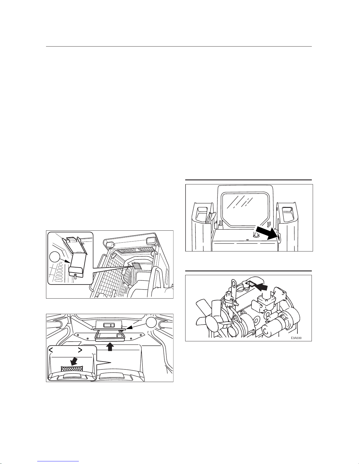
Manual storage
A compartment for storing this manual
is provided at the position shown in the
diagram below.
1. Insert the starter key and turn it
counterclockwise to unlock the cover (1).
2. Open the cover (1).
3. After using the manual, place it in the
plastic pouch and store it in the manual
storage.
Type A
Type B
1
T7A0012
Page 5
3
MACHINE DESCRIPTION
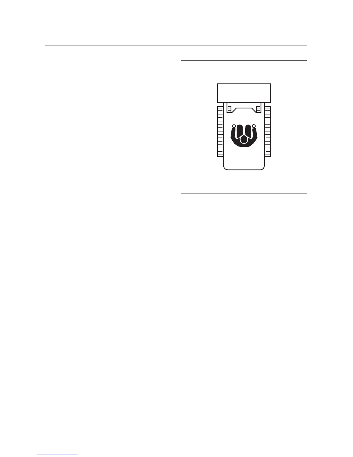
Front, rear, Ieft and right
This manual refers the front, rear, left and
right of the machine as seen when sitting in
the operator’s seat with the bucket visible to
the front.
Designated operations
Use this machine primarily for the following
operations:
Carrying
Leveling
Loading
Features
Hydrostatic drive system
Roll Over / Falling Object Protective Structure (ROPS/FOPS), tilt-up ROPS
Low engine noise and exhaust emissions
Two-way auxiliary hydraulics
Pilot-operated joystick controls
Break-in period
When the machine is new, follow the instructions below when operating the machine for the
first 100 hours (as indicated on the hourmeter).
Using a new machine roughly without breaking it in will lead to quicker deterioration of machine
performance and may shorten the machine’s service life.
Warm up the engine and hydraulic oil sufficiently.
Avoid heavy loads and rapid operations. Operate with a load of about 80% of the maximum
load.
Do not start up, accelerate, change directions, or stop abruptly unless necessary.
RIGHTLEFT
REAR
FRONT
T7A004E
Page 6

4
Page 7

5
CONTENTS
Introduction ..........................................2
Machine Description ..........................
3
Safety ....................................................
7
Controls ............................................. 39
Operation ........................................... 69
Transport ........................................... 95
Maintenance ................................... 101
Troubleshooting .............................. 155
Specifications ................................. 169
Options ............................................ 179
Index ................................................. 193
Page 8

6
Page 9

7
General Precautions ......................................... 8
Preparing Precautions ...................................15
Starting Precautions .......................................17
Operating Precautions ...................................19
Stopping Precautions .....................................26
Transporting Precautions ..............................27
Maintenance Precautions ..............................28
Safety Signs (Decals) ......................................35
SAFETY
Page 10
SAFETY
8
General Precautions
Observe all safety rules
Operation, inspection and maintenance
of this machine must be performed only
by trained and qualified persons.
All rules, regulations, precautions and
safety procedures must be understood
and followed when performing operation,
inspection and maintenance of this
machine.
Do not perform any operation, inspection
and maintenance of this machine when
under the adverse influence of alcohol,
drugs, medication, fatigue, or insufficient
sleep.
Wear appropriate clothing and
personal protective equipment
Do not wear loose clothing or any
accessory that can catch on controls or in
moving parts.
Do not wear oily or fuel-stained clothing
that can catch fire.
Wear a hard hat, safety shoes, safety
glasses, filter mask, heavy gloves, ear
protection and other protective equipment
as required by job conditions. Wear
required appropriate equipment such as
safety glasses and filter mask when using
grinders, hammers or compressed air,
because metal fragments or other objects
can fly and cause serious injury.
Use hearing protection when operating
the machine. Loud prolonged noise can
cause hearing impairment, even the total
loss of hearing.
Operating temperature range
To maintain the performance of machine and
to prevent it from early wear, observe the
following operating conditions.
Do not operate the machine if the ambient
temperature is higher than +45°C (+113°F)
or lower than –15°C (+5°F).
If operated at an ambient temperature of
higher than +45°C (+113°F), the engine
may overheat and cause the engine oil to
degrade.
If operated at an ambient temperature of
lower than –15°C (+5°F), the parts made of
rubber such as gaskets may get hardened
to cause an early wear or damage to the
machine.
If the machine is to be used outside the
ambient temperature range described
above, consult your sales or a service
dealer.
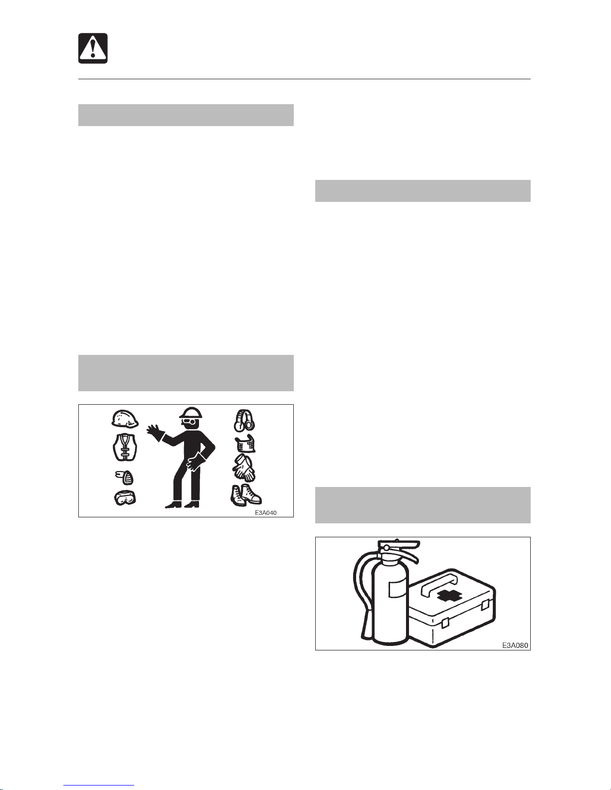
Provide a fire extinguisher and
first aid kit
Know where a fire extinguisher and first
aid kit are located and understand how to
use them.
Know how to contact emergency
assistance and first aid help.
Page 11
9
SAFETY
General Precautions
Never remove safety equipment
Make sure all protective guards, canopies,
doors, etc., are in place and secure. Repair
or replace damaged components before
operating the machine.
Know how to use the safety bar, seat belt
and other safety equipment and use them
properly.
Never remove any safety equipment
except for service. Keep all safety
equipment in good operating condition.
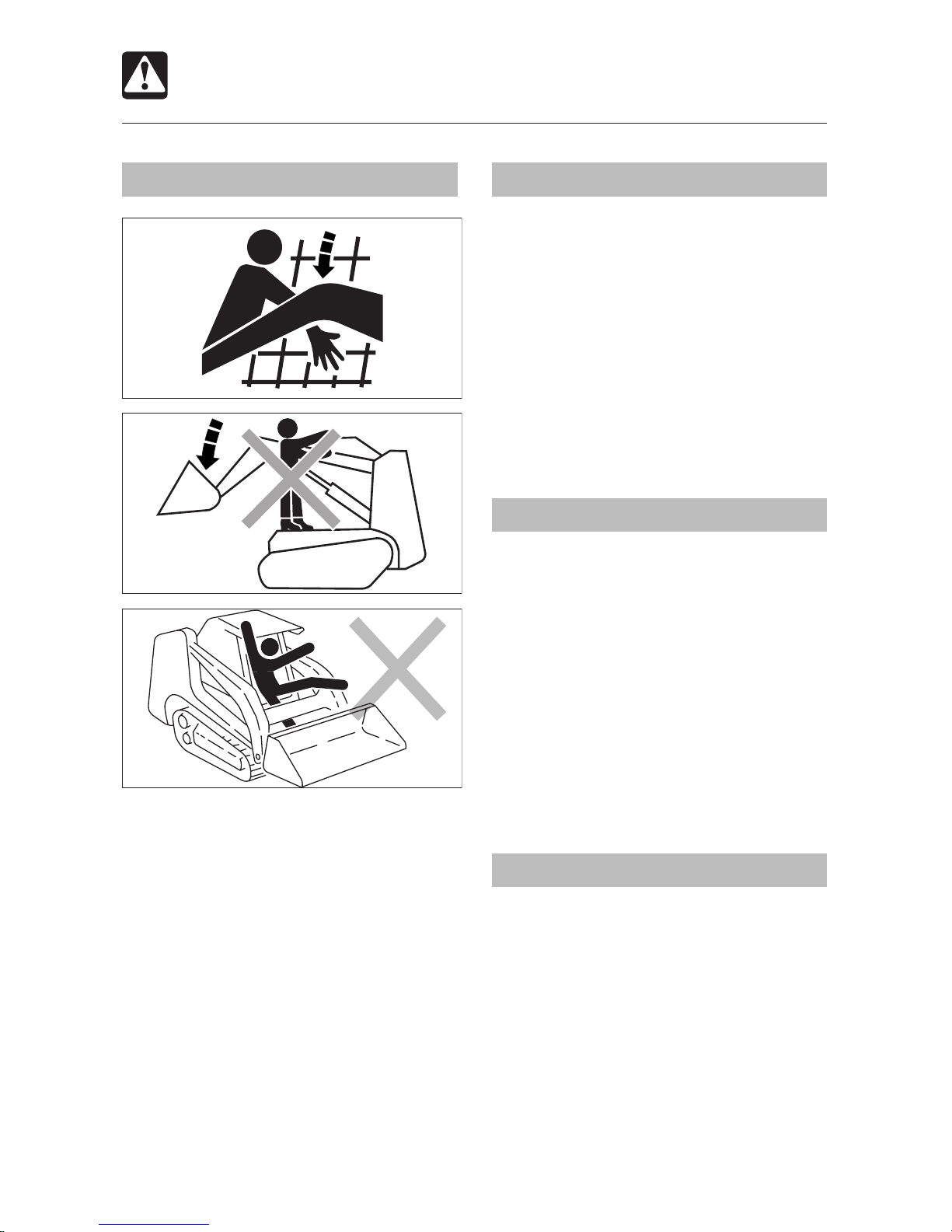
Crush Hazard
FOPS Limitations
Various classes and sizes of off-road equipment
operate in a wide variety of applications and
environmental conditions.
With the intention of providing operators with
reasonable protection from falling objects,
two levels of FOPS (Falling-Object Protective
Structure) acceptance criteria have been
developed based on end use:
Level 1 ...protection from falling bricks,
small concrete blocks and hand
encountered in operations such as
highway maintenance, landscaping
and other construction site services.
Level 2 ...protection from falling trees or rocks
for machines involved in site clearing,
overhead demolition or forestry.
This machine is equipped with a Level 1 FOPS as
standard equippment. DO NOT use this machine
in an application that may involve the hazards of
falling trees or rocks. If Level 2 FOPS protection
is required in your application, contact your dealer
or the manufacturer concerning the possible
availability of such protection.
T7A005
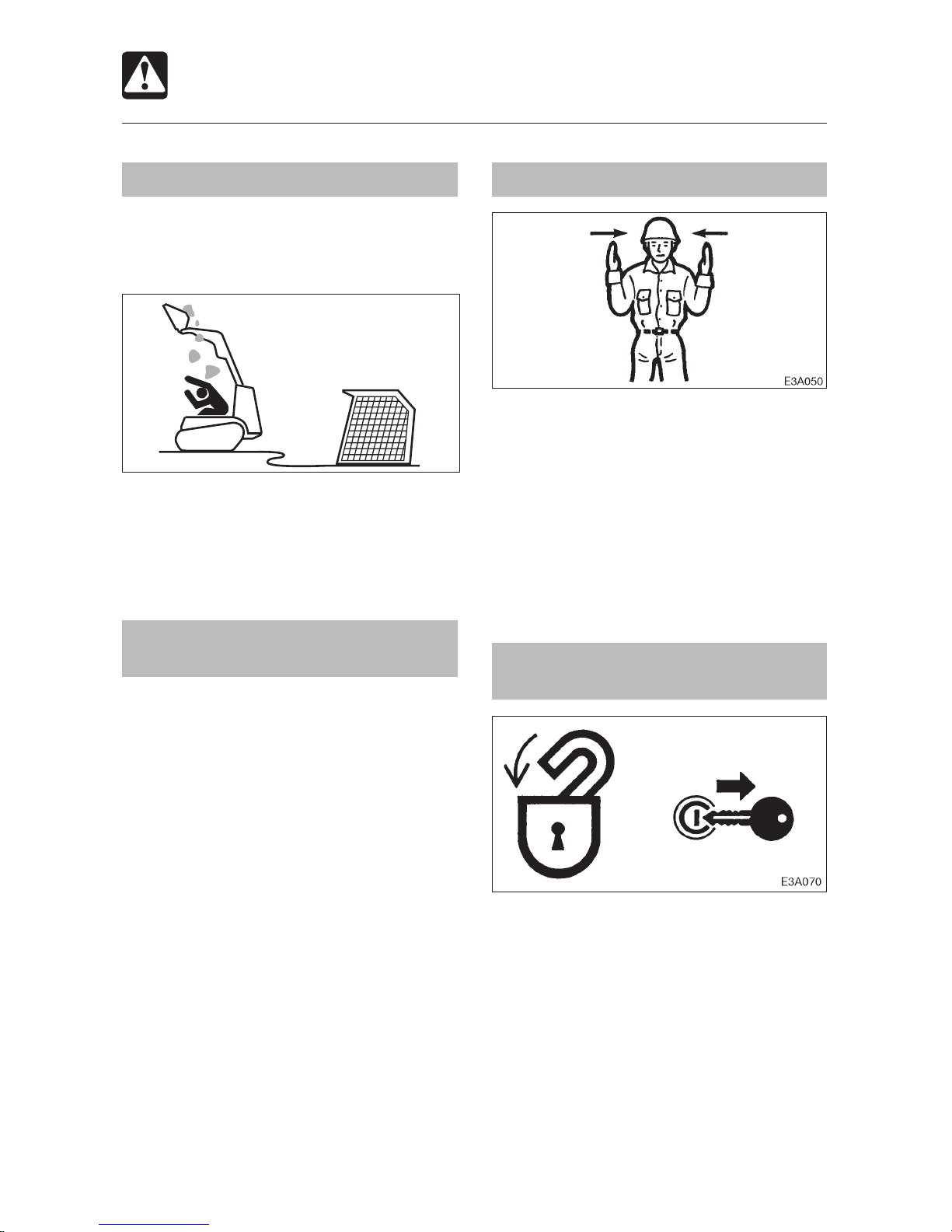
Use a signal person and flagman
Know and use the hand signals required for
particular jobs and make sure who has the
responsibility for signaling.
All personnel must fully understand all the
signals.
The operator shall respond to signals only
from the appointed signal person, but
shall obey a stop signal at any time from
anyone.
The signal person must stand in a clearly
visible location when giving signals.
Be sure to raise the safety bar
before leaving the operator’s seat
Before leaving the operator’s seat:
• Lower the lift arms to the ground or
engage the lift arm stop.
• Stop the engine.
• Raise the safety bar to engage the lock.
• Remove the key and take it with you.
If any controls are touched accidentally
when the safety bar is lowered, the
machine will move suddenly, and cause
serious injury or death.
Page 12
SAFETY
10
General Precautions
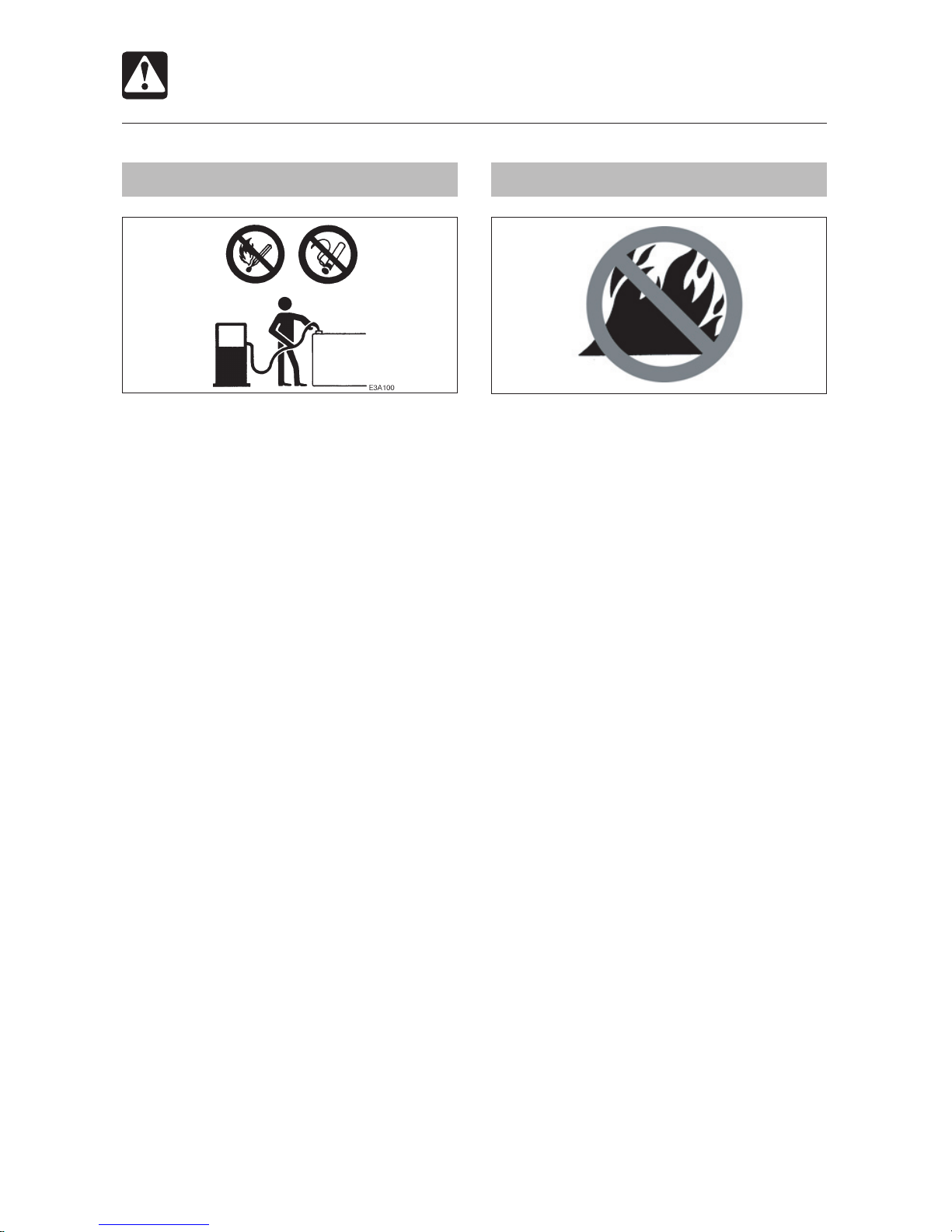
Avoid fire and explosion hazards
Keep flames away from fuel, hydraulic fluid,
oil, grease and antifreeze. Fuel is particularly
flammable and dangerous.
When handling these combustible
materials, keep lit cigarettes, matches,
lighters and other flames or sources of
flames away.
Do not smoke or permit open flames while
fueling or near fueling operations.
Never remove the fuel cap or refuel with
the engine running or hot. Never allow fuel
to spill on hot machine components.
Clean up spilled fuel, oil and other
flammable fluids immediately.
Check for fuel, oil and hydraulic fluid leaks.
Stop all leaks and clean the machine
before operating.
Do not cut or weld on pipes or tubes that
contain flammable fluids. Clean thoroughly
with nonflammable solvent before cutting
or welding.
Remove all trash and debris from the
machine. Make sure that oily rags and
other flammable material are not stored
on the machine.
Handle all solvents and dry chemicals
according to procedures identified on
manufacturers’ containers. Work in a wellventilated area.
Never use fuel for cleaning purposes.
Always use a nonflammable solvent.
Store all flammable fluids and materials
in a safe, fireproof and well-ventilated
place.
Fire prevention
When working in a certain environment, it is
impossible to prevent combustible debris
from collecting in the machine. This debris,
in itself, may cause a fire; however, when
mixed with fuel, oil or grease in a hot or
confined place, the danger of fire is greatly
increased.
The following fire prevention guidelines
should be used to supplement the operator’s
fire prevention efforts. In no case should
the guidelines be used, or assumed, as
replacements for diligent operator efforts
at preventing fires. (that include regular
schedule of cleaning and inspecting the
machine as conditions require.)
The following guidelines will help to keep
your equipment up and running efficiently
and keep the risk of fire to a minimum.
1. Maintain a CHARGED fire extinguisher
on or near the machine at all times and
KNOW HOW TO USE IT.
2. Remove debris and blow out dust regularly
from side air intake areas, engine radiator,
hydraulic oil cooler, air conditioning
condenser core to prevent overheating of
the engine and hydraulics and to maintain
efficient operation of the machine.
3. Blow off all accumulated debris near hot
engine exhaust components (turbocharger
and exhaust manifold as well as exhaust
pipes and muffler) at the completion of
each work shift or more frequently when
AU1E001
Page 13

11
SAFETY
General Precautions
working in severe conditions where
large amounts of combustible debris
are present. Engine exhaust systems
provide numerous small pockets where
flammable debris can gather. Even small
accumulations close to hot exhaust
components can ignite and smolder.
4. Clean out all accumulated debris (twigs,
pine needles, branches, bark, leaves,
saw dust, small wood chips) and any
other combustible materials from inside
the machine belly pans or lower machine
structures as well as from areas in
proximity to the engine, fuel and hydraulic
oil systems no less frequently than at the
completion of each work shift.
5. Inspect the machine regularly for any
signs of diesel fuel or hydraulic system
leakage. Check for worn or damaged fuel
or hydraulic lines before starting up any
equipment.
6. Clean up any grease, diesel fuel, hydraulic
and lubricating oil accumulation and
spillage immediately.
7. Steam clean the engine, and belly pan areas
at least once a month or more frequently
when working in sever conditions where
large amounts of combustible debris are
present.
8. Use only nonflammable solutions for
cleaning the machine and components.
9. Inspect the exhaust system daily for any
signs of leakage. Check for worn, cracked,
broken or damaged pipes or muffler. Also
check for missing or damaged bolts or
clamps. Should any exhaust leaks or
defective parts be found, repairs must
be made immediately. Engine exhaust
leaks can cause fires. Do not operate
the machine until the exhaust leak is
repaired.
10. During daily operation of the machine,
the occurrence of exhaust leaks are
usually accompanied by a change or
increase in engine exhaust noise levels.
These audible warnings cannot be
ignored. Should any exhaust leaks occur
during operation, the machine must be
shut down immediately and not put back
to work until the necessary repairs have
been completed.
11. Before starting repair work, such as
welding, the surrounding area should be
cleaned and a fire extinguisher should be
close by.
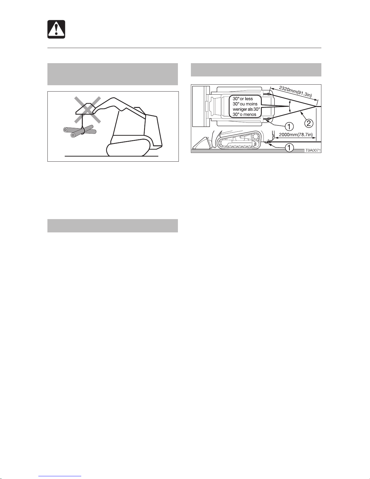
12. Do not use the machine on top of or to
push piles of burning timber. A machine
fire will likely result.
What to do to prepare for a machine
fire
Prevent the fire from happening in the
first place by ensuring that all machine
systems are frequently inspected and
always well maintained.
Ensure that any hand held fire extinguishers
are charged and in working order. Fire
extinguishers require routine care. Follow
the manufacturer’s instructions for
inspection and maintenance shown on
the label of the fire extinguisher and in the
extinguisher manufacturer’s manual.
Ensure that you follow all national, state
/ provincial and local regulations dealing
with fire fighting in effect in your specific
geographic region.
Ensure that all information necessary for
you to immediately contact all sources
of help (local fire department, etc) in the
event of a fire emergency is recorded and
readily available at all times.
Page 14

SAFETY
12
General Precautions
What to do if a machine fire occurs
If operating the machine when a fire occurs:
1. Lower all working attachments to the
ground.
2. Shut the engine off.
3. Exit the machine. Call for help. Be
certain to report a fire immediately.
4. At all times ensure your own personal
safety and the safety of anyone that
may be in the area. Approach any fire
with extreme caution. All fires can be
very dangerous and life threatening.
Before deciding to fight the fire, be certain
that:
1. The fire is small and not rapidly
spreading.
2. There is always a clear, safe escape
route.
3. You have received training in the use of
the available fire extinguishing devices
and are confident that you can operate
them effectively.
Be aware that engine coolant, diesel fuel
or hydraulic hoses could fail during a fire.
If this happens, hot coolant, fuel or oil
could possibly be ignited by the fire.
If in any doubt about whether or not to
fight the fire – DON’T. Instead stand well
clear of the fire and wait for help to arrive.
Use the PASS method. This is the most
effective use of a fire extinguisher.
•
Pull the pin at the top of the extinguisher
that keeps the handle from being
pressed. Break the plastic seal as the
pin is pulled.
•
Aim the nozzle at the base of the fire. Do
not aim the nozzle at the flames. In order
to put out the fire, you must extinguish
the fuel, not the flames. Hose nozzles
are often clipped to the extinguisher
body. Release the hose before taking
aim.
•
Squeeze the handle to release the
pressurized extinguishing agent. The
handle can be released at any time to
stop the discharge.
•
Sweep from side to side at the base of
the fire until the fire is completely out or
the fire extinguisher is empty
Only if you can safely do so, open the
access panels to the machine in the area
of the fire.
Failing all attempts to access the machine
compartment, discharge the extinguisher
through the mesh or any available
openings on the machine.
Ensure that the machine and all
components have cooled down
sufficiently after a fire so that re-ignition
does not occur.
Remain in the area until help arrives.
What to do after a machine fire has
occurred
Before returning the machine to work.
1. Ensure that the cause of the fire is
determined and all appropriate repairs
are completed.
2. Ensure that all extinguishers used
in fighting the fire are replaced or
recharged.
Notify your equipment dealer and / or
GEHL Manufacturing.
Page 15

13
SAFETY
Exhaust fumes from the engine
can kill
Do not operate the engine in an enclosed
area without adequate ventilation.
If natural ventilation is poor, install
ventilators, fans, exhaust extension pipes
or other artificial venting devices.
Handling asbestos dust
Inhaling asbestos dust has been linked to
lung cancer. When handling materials which
may contain asbestos, take the following
precautions:
Never use compressed air for cleaning.
Avoid brushing or grinding of the
materials.
For clean up, use wet methods or a
vacuum equipped with a high efficiency
particulate air (HEPA) filter.
Wear an approved respirator if there is
no other way to control the dust. When
working indoors, install a ventilation
system with a macro molecular filter.
General Precautions
Page 16
SAFETY
14
General Precautions
Be careful not to get crushed or cut
Your body, hands and feet must not enter
between moving parts, such as between
lift arms and main body, or between lift
arms and bucket. When operating lift arms
and bucket, the gap between the moving
parts will be changing, and getting caught
in between can cause serious injury or
death .
The lift arms move close to the outside of
the side screens; never stick out arms or
other portions of your body from the side
screens.
The lift arms move close to the ROPS;
therefore, do not stand or lean on the
machine.
T7A007
T7A008
T8A006
Using optional products
Consult with a Gehl dealer before installing
optional attachments.
Do not use attachments that have not
been approved by Gehl. Doing so may
compromise safety or adversely affect the
machine’s operation or service life.
Gehl will not be responsible for any injuries,
accidents or damage to its products
caused by the use of a non-approved
attachment.
Product usage
Keep in mind that the use of high-output
brush cutter attachments on this unit can
only be used in part-time, lighter-duty brush
clearing applications, with appropriate
cooling system care and in moderate
ambient temperatures. Care with respect to
usage and prevention of track damage must
also be adhered to.
This usage notice also applies to all
other high-performance, high-demand
attachments.
Never modify the machine
Unauthorized modifications to this machine
can cause injury or death. Never make
unauthorized modifications to any part of
this machine.
Page 17
15
SAFETY
Preparing Precautions
Know the working area
Before starting operation, know the working
area to ensure safety.
Check the topography and ground
condition of the working area, or the
structure of the building when working
indoors, and take the necessary safety
measures in dangerous spots.
Note and avoid all hazards and obstructions
such as ditches, underground lines, trees,
cliffs, overhead electrical wires and areas
where there is danger of a slide.
Check with the local utilities for the
locations of buried gas and water pipes
and buried power cables. Determine
jointly what specific precautions must be
taken to ensure safety.
When working on roads, be sure to take
into account the safety of pedestrians and
vehicles.
• Use a flagman and/or signals.
• Fence off the working area and prohibit
entry to unauthorized persons.
When working in water or crossing shallow
streams or creeks, check the depth of the
water, the firmness of the ground, and the
speed of the current beforehand. Make
sure the water is not deeper than the
allowable depth.
Refer to the section titled “Cautions on
Use in Water” for further instructions.
Check the strength of the bridge
When travelling over a bridge or other
structure, check the permissible load. If the
strength is insufficient, reinforce it.
Always keep the machine clean
Clean windows, mirrors and lights to
ensure good visibility.
Wipe off any oil, grease, mud, snow and
ice, to prevent accidents due to slipping.
Remove all loose objects stored in the
machine and all objects that do not belong
in or on the machine and its equipment.
Remove any dirt, oil and grease from the
engine area, to prevent fires.
Clean the area around the operator’s seat,
removing any potential obstacles.
T7A009
T7A025
T3A004
Page 18
SAFETY
16
Preparing Precautions
Perform inspection and
maintenance daily
Failure to notice and repair machine
malfunctions or damage can lead to
accidents.
Before operating, perform the prescribed
inspections and make repairs immediately
if any malfunctions are found.
If a failure that causes loss of control,
such as steering, service brakes or engine
occurs, stop the machine motion as
quickly as possible, follow the shutdown
procedure, and keep machine securely
parked until the malfunction is corrected.
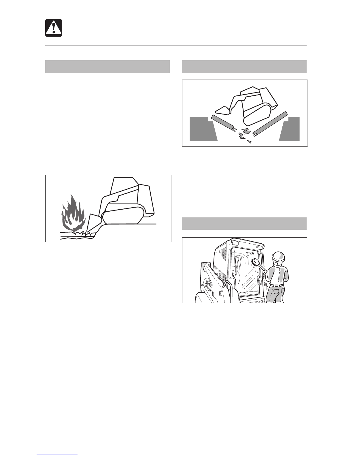
Emergency Exit
If you become trapped inside the cab,
remove the rear window to get out.
There are two ways to remove the rear
window.
In case of emergency
Kick off the rear window. Note that the glass
may break. Be careful not to get injured.
In case of need
1. Pull off ring (A) and remove the tip of the
rubber wedge.
2. Grasp the tip, pull, and remove the entire
rubber wedge.
3. Pull inside knob (B).
E X I T
T8B001
A
B
Page 19
17
SAFETY
Starting Precautions
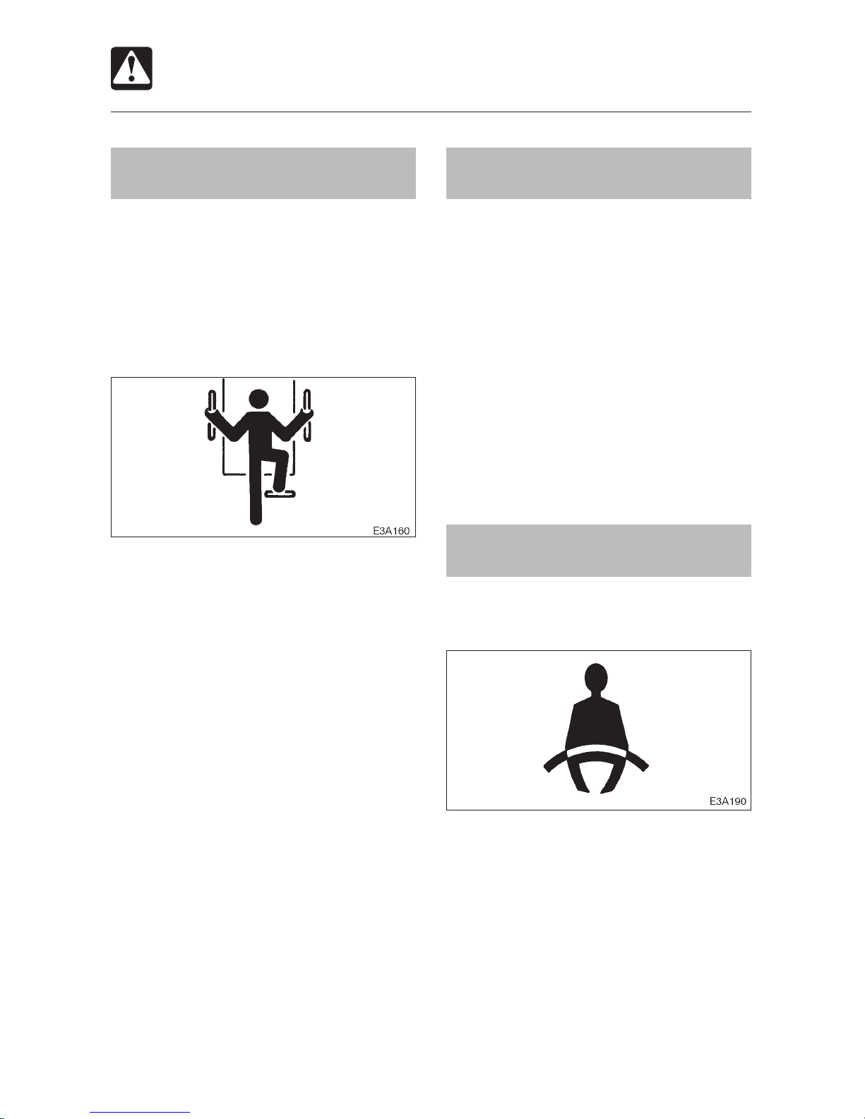
Maintain three-point contact
when mounting and dismounting
Do not jump on or off the machine. Never
attempt to mount or dismount a moving
machine.
For machines with cab, when mounting
and dismounting the cab, first open the
door fully to the locked position and check
that it does not move.
Always face the access system and
maintain a three-point contact with the
recommended handrails and steps while
getting on and off the machine. Keep
steps and platform clean.
Never use the control levers as hand
holds.
Do not go under the raised lift arms if they
are not sufficiently supported.
Lower the lift arms to the ground before
mounting or dismounting the cab.
Clear the area of other persons
before starting the machine
Do not start the engine until you are sure it
is safe. Before starting, check or perform the
following.
Walk around the machine and warn all
personnel who may be servicing the
machine or are in the machine path. Do
not start until all personnel are clearly
away from the machine.
Check for any “DO NOT OPERATE” tags
or similar warning notices on the cab door,
controls and ignition switch.
Sound horn to alert everyone around the
machine.
Start the engine from the
operator’s seat
Adjust, secure and latch the operator’s
seat.
Fasten the seat belt.
Check that the parking brake is applied
and place all controls in the neutral
position.
Check that the safety bar is in the lock
position.
Clear the area of all persons.
Start and operate the engine from the
operator’s seat only.
Never attempt to start the engine by
shorting across the starter terminals.
Page 20

SAFETY
18
Starting Precautions
Starting with jumper cables
Use jumper cables only in the recommended
manner. Improper use of jumper cables can
result in battery explosion or unexpected
machine motion.
Refer to the section titled “If the Battery Goes
Dead” for proper instructions.
After starting the engine
After starting the engine, perform the
following operations and checks in a safe
place with no persons or obstacles in the
area. If any malfunctions are found, follow
the shutdown procedure and report the
malfunction.
Warm up the engine and hydraulics.
Observe all gauges and warning
instruments for proper operation.
Listen for unusual noises.
Test engine speed control.
Operate each control to ensure proper
operation.
In cold weather
Be careful of slippery conditions on
freezing ground, steps and hand holds.
In severe cold weather, do not touch any
metal parts of the machine with exposed
flesh, because flesh can freeze to the
metal and cause injury.
Do not use ether or starting fluids on this
engine. These starting aids can cause
explosion and serious injury or death.
Warm up the engine and hydraulic fluid
before operating.
Page 21
19
SAFETY
Operating Precautions
Ensure good visibility
When working in dark places, turn on the
machine’s working lights and headlights
and/or provide extra stationary lighting if
necessary.
When visibility is poor due to severe
weather (fog, snow or rain), stop operating
the machine and wait until conditions
improve.
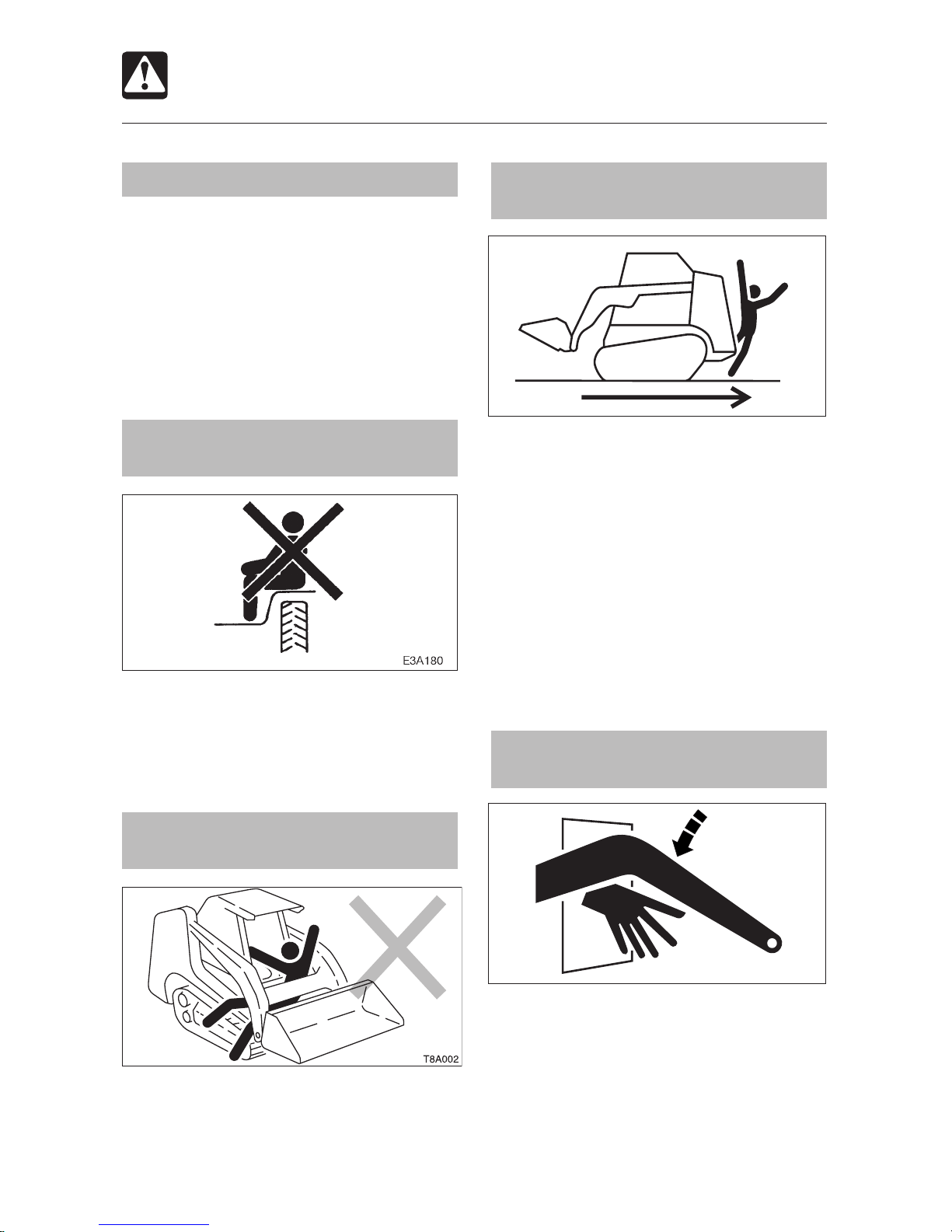
Do not permit riders on the
machine
Do not allow anyone to ride on any part of
the machine at any time while traveling.
Do not allow anyone to be on any part of
the machine while operating.
Operate the machine only from
the operator’s seat
Operate all the controls only from the
operator’s seat. Failure to do so can cause
serious injury or death.
Check for safety in the
surrounding area before starting
Understand the machine limitations.
Use a signal person where clearances are
close or your vision is obstructed.
Never allow anyone to enter the turning
radius and machine path.
Signal your intention to move by sounding
the horn.
There are blind spots to the rear of the
machine.
If necessary, before backing up, check
that the area is safe and clear.
Keep your body inside the
operator’s cab
Keep your body inside the operator’s
compartment while operating the loader.
Never work with your arms, feet or legs
beyond the operator’s compartment.
T7A010
T7A011
Page 22
SAFETY
20
Operating Precautions
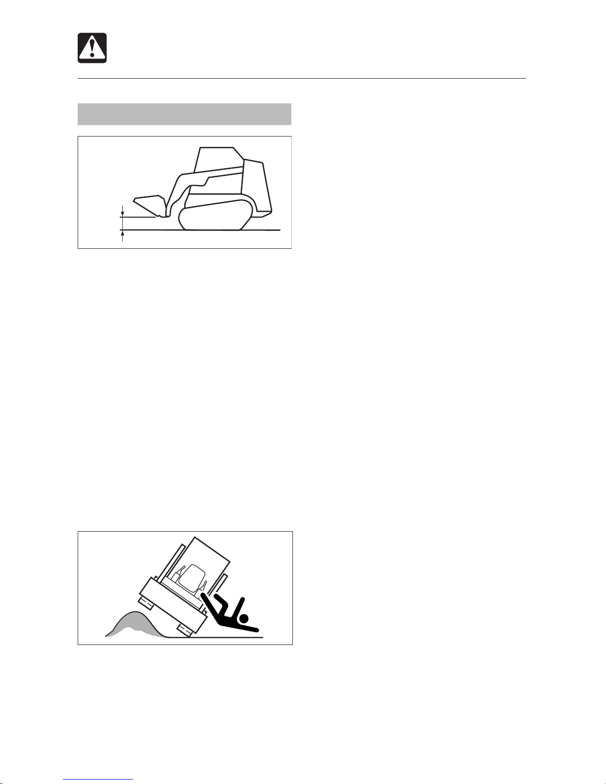
Cautions on traveling and turning
Traveling and turning should be performed
with the bucket cylinder fully retracted and
the bucket at a height of approximately 30
cm (12 in.) from the ground.
Avoid sudden stops, starts and turns.
Do not raise the safety bar while traveling.
This is dangerous, because raising the
safety bar will cause the parking brakes
of the travel motors to operate and apply
the brakes abruptly.
Do not switch off the ignition switch while
traveling. Doing so will cause sudden
braking and is dangerous.
Before backing up, visually check for
safety to the rear. Backing up without
checking could result in contact with a
worker or obstacle.
If the working equipment must be operated
while traveling, do so with extra care.
When traveling, try not to cross over
obstacles. When crossing over something
cannot be avoided, keep the bucket close
to the ground and travel slowly. Also note
that the machine must not cross over an
obstacle with the machine body on an
extreme slope (of 15 degrees or more).
When traveling on rough terrain or when
carrying a load, lower the load and travel
slowly.
T7A013
T7A012E
30 cm
(12 in.)
Page 23
21
SAFETY
Operating Precautions
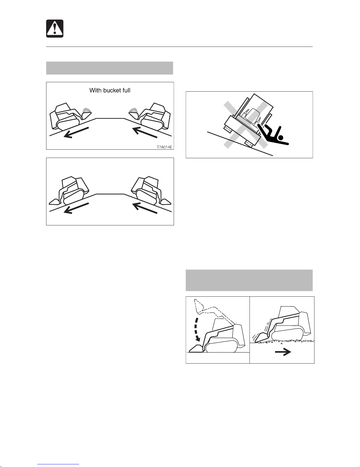
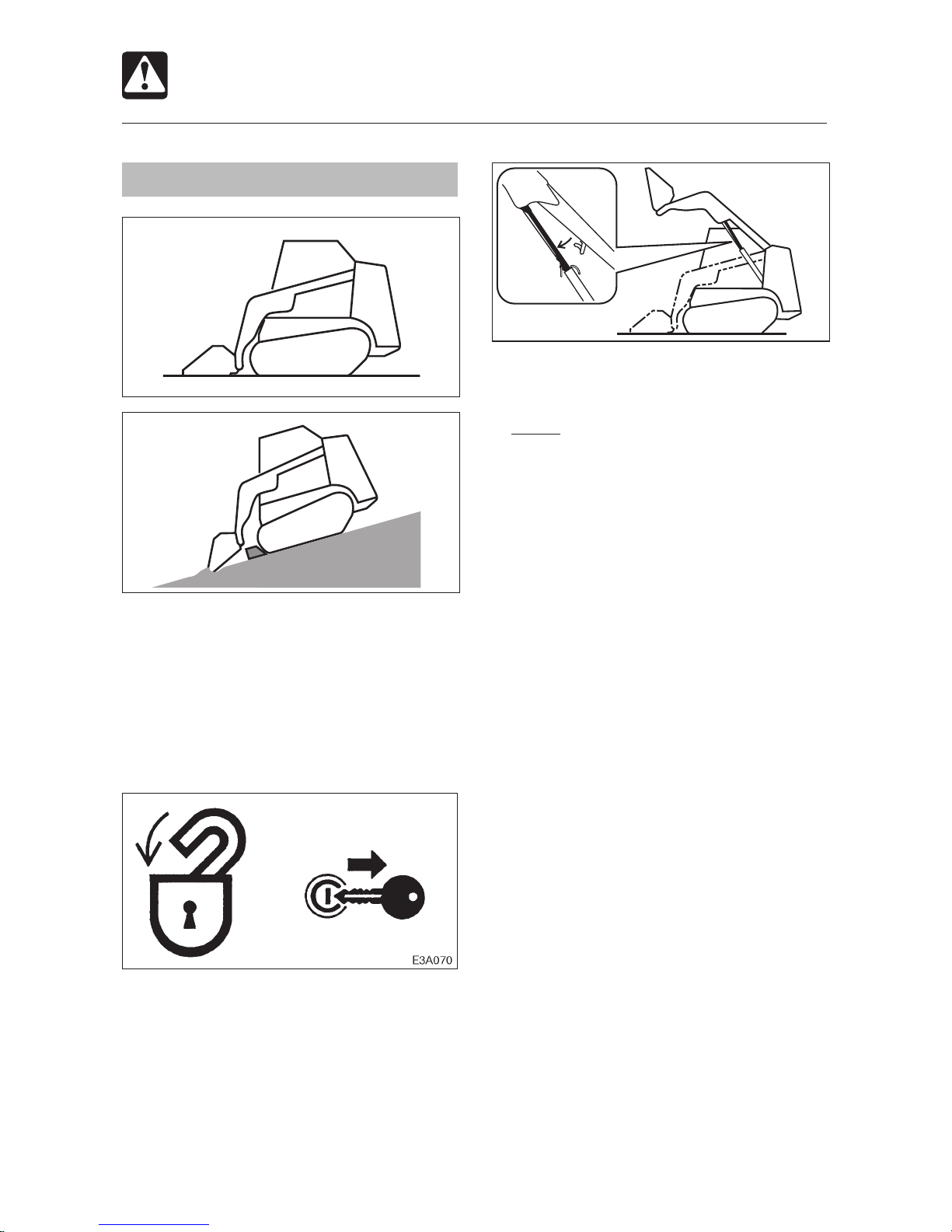
Cautions on traveling on slopes
Work should not be performed on a slope,
because the stability of the machine can
be adversely affected when operating
the working equipment and there is the
possibility of the machine tipping over.
When traveling on a slope, be cautious of
tipping over or sliding sideways.
When traveling on a slope, position the
heavier end of the machine (front or back,
whichever is heavier) pointing up the slope.
When going up or down slopes having a
gradient of 15 degrees or more, travel up
and down slope with the heavy end of the
machine pointed uphill.
When traveling on a slope, lower the
bucket to a height of 20 to 30 cm (8 to
12 in.) above the ground, and in case of
an emergency, lower the bucket to the
ground and stop the machine.
Travel at slow speeds on slopes. Especially
when going down slopes, reduce the
engine (r.p.m.) speed and set the stroke of
the left control lever to half or less before
going down. Going down a slope too fast
will lead to loss of control.
Sudden stopping on a sloped road may
lead to loss of stability and the machine
could tip over.
Traveling across an inclined surface at
an angle or traveling straight across an
inclined surface could result in slipping
sideways or tipping over. Travel straight
up and down the slope.
When traveling over grass or fallen
leaves, wet iron plates or frozen surfaces,
the machine might unexpectedly slide
sideways when on even a slight slope.
Do not allow the machine to become
positioned across the slope.
Use caution when floating the lift
arms
Make sure the bucket is lowered to the
ground before actuating the lift arms Float
control.
Actuating the Float control when the lift
arms are raised will cause the bucket to
fall rapidly and is extremely dangerous.
Do not drive the loader forward with the lift
arms in Float position.
T7A015E
With bucket empty
T8A0051
T7A0161
Page 24
SAFETY
22
Operating Precautions
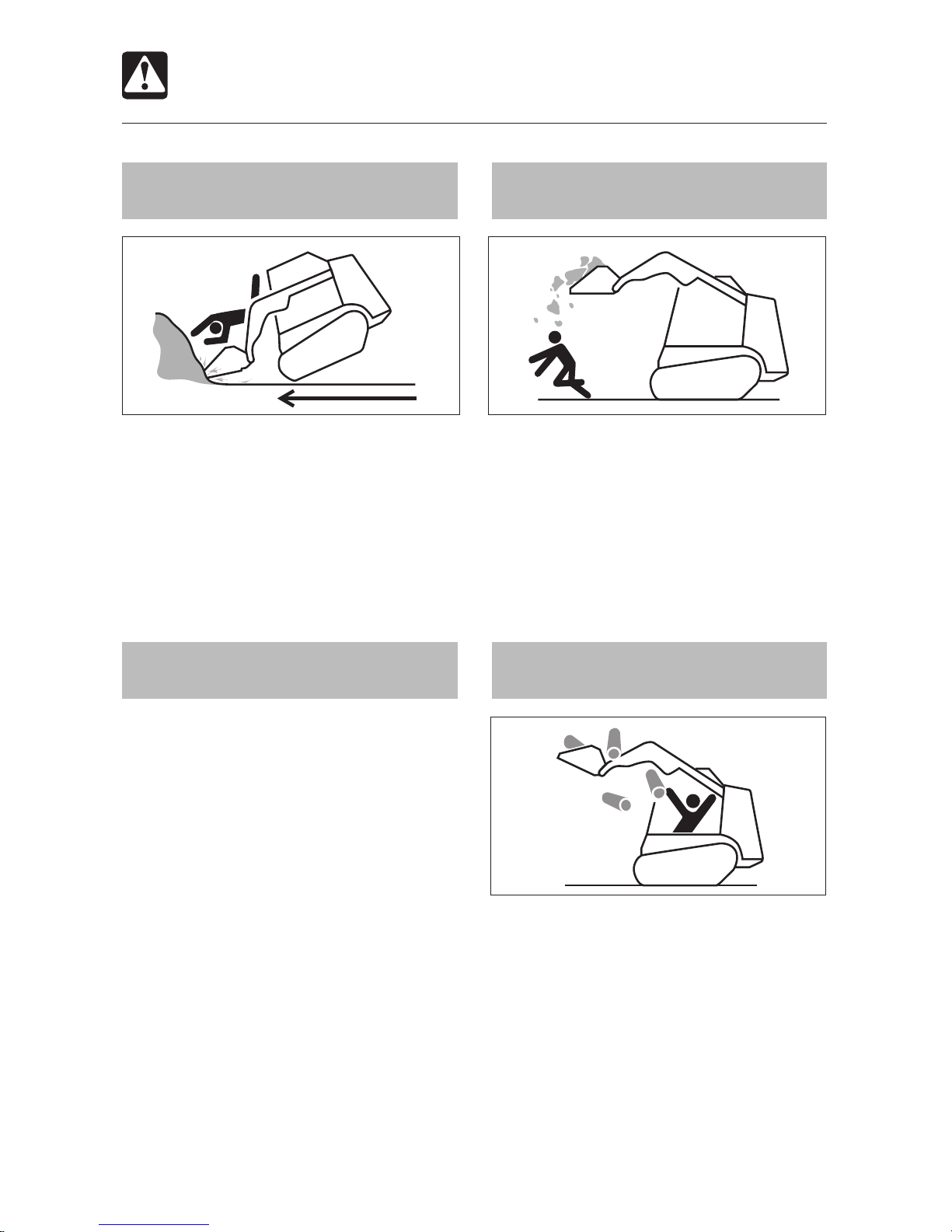
Do not drive into materials at high
speeds
Driving at high speed into the materials you
are handling can lead to your body striking the
machine or being thrown from the machine.
Check the conditions surrounding the area
in front of the material you are handling and
work at low speeds.
Operate on snow or ice with extra
caution
When traveling on snow or frozen
surfaces, keep the machine travel speed
down and avoid accelerating, stopping
and changing directions abruptly.
Remember that the road shoulder, fences,
etc., may be buried in the snow and not
visible.
Lower the bucket when parked on unsure
ground conditions.
Do not carry the bucket over the
heads of people
Carrying the bucket over the heads of people
entails the danger of the load spilling or the
bucket suddenly dropping.
Caution against falling unstable
loads
Unstable loads such as round items,
cylindrical items, and stacked plates entail
the possibility of falling from the bucket.
When handling unstable loads, operate
carefully to avoid raising the bucket too high
or tilting it too far rearward.
T7A017
T7A018
T7A019
Page 25
23
SAFETY
Operating Precautions
Do not suddenly stop or lower the
working equipment
Sudden lowering or stopping of the working
equipment could cause the machine to tip
bowed forward.
Operate the working equipment carefully,
especially when the bucket is loaded.
Avoid overloading and off-center
loads
Filling the bucket in excess of the maximum
load and loading an off-center load will cause
the machine to become unstable and could
result in the machine tipping over. Loading
should be done evenly, should be less than
the: CTL55: 565 kg (1246 lbs.); CTL65: 835
kg (1841 lbs.); CTL75: 945 kg (2083 lbs.);
CTL85: 1190 kg (2624 lbs.).
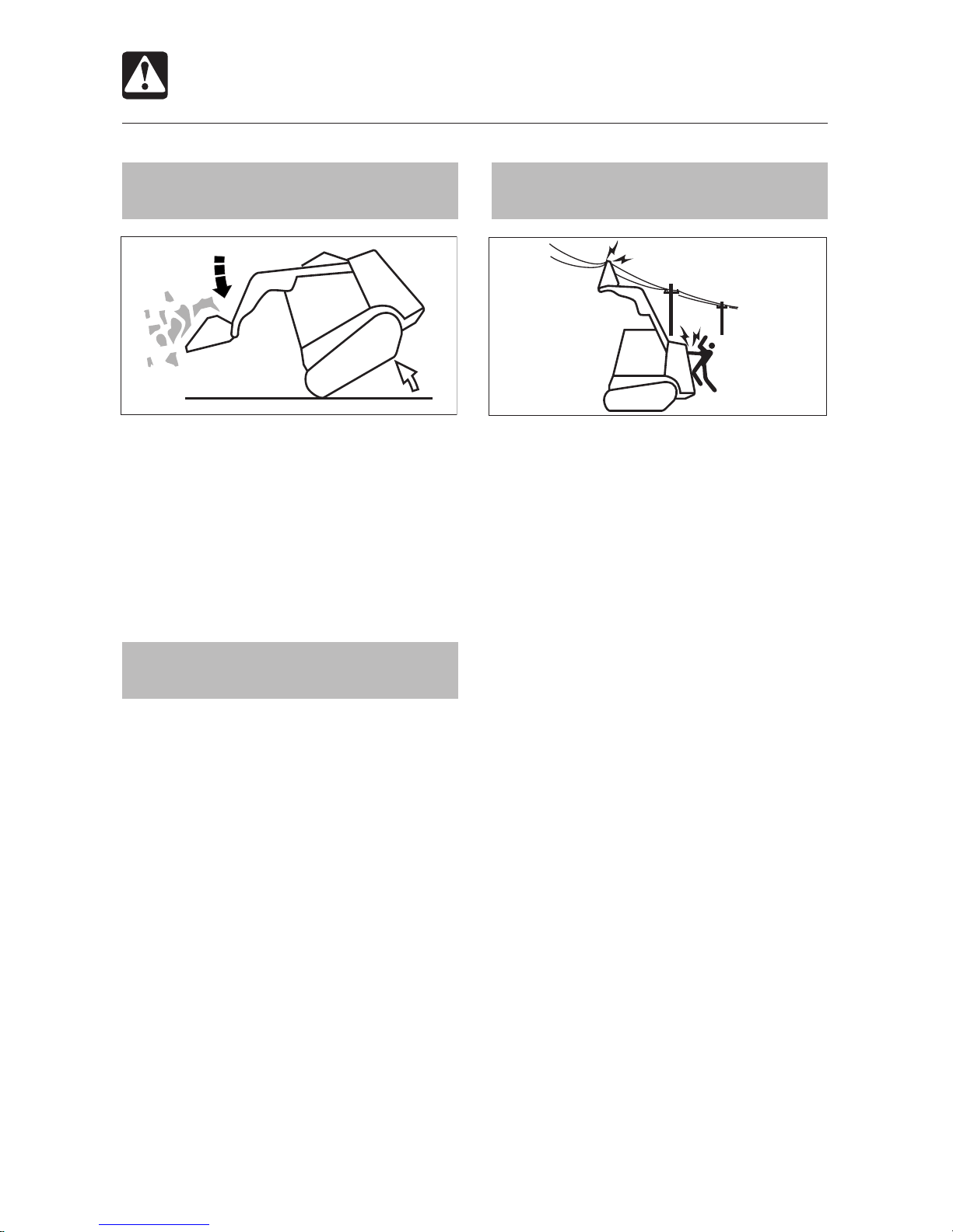
Keep a safe distance from
electrical power lines
Never approach power lines with any part of
the machine and its load unless all local and
national required safety precautions have
been taken. Electrocution and death can
result from arcing, touching or even being
close to a machine that is in contact with or
near an electrical source.
Maintain the maximum possible distance
from power lines and never violate the
minimum clearance.
Always contact the nearest electric
utility and determine jointly what specific
precautions must be taken to ensure
safety.
Consider all lines to be power lines and
treat all power lines as energized, even if
it is known or believed that the power is
shut off and the line is visibly grounded.
Use a signal person to observe the
approach of any part of the machine or
load to the power line.
Caution all ground personnel to stand
clear of the machine and the load at all
times.
If the machine should come in contact
with a live electrical source, do not leave
the operator’s seat. Do not allow anyone
to approach or touch the machine.
Be especially careful of buried high-
voltage power lines.
T7A020
T7A029
Page 26
SAFETY
24
Operating Precautions
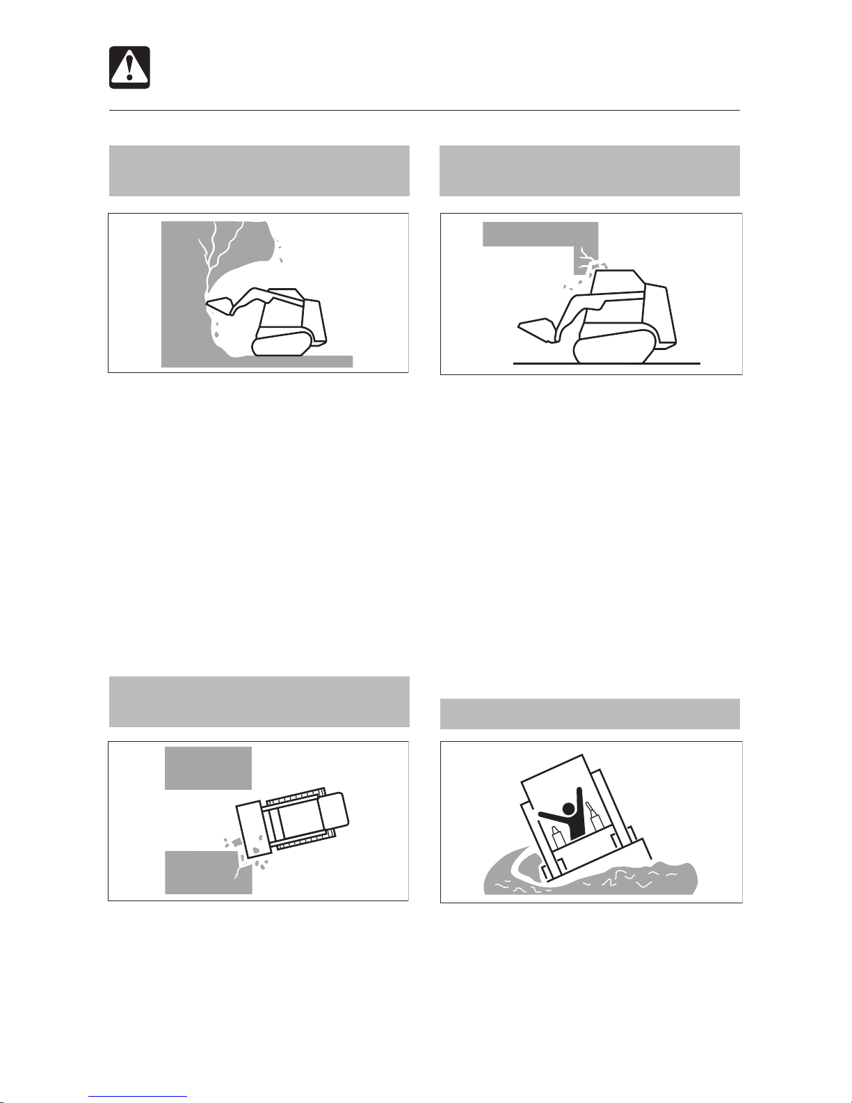
Watch out for hazardous working
conditions
Never undercut a high bank. Be particularly
alert for the possibility of a cave-in.
Do not operate in places where there is a
danger of falling rocks.
Do not approach unstable surfaces (cliffs,
road shoulders, deep trenches, etc.). The
ground may give way under the machine’s
weight or vibrations, causing the machine
to tip over.
• The ground is weak after rain or
explosions.
• The ground is also unstable on banks
and near dugout trenches.
Travel in narrow or congested
places
To avoid contact accidents, pay attention to
the surroundings at narrow sites, indoors,
and congested places and operate at
speeds at which the machine can be safely
operated.
Precautions when passing
through tunnels or near high walls
Careless entry into tunnels or places with
high walls can lead to serious accidents,
such as contact accidents, etc. Check
height and width limits in advance and verify
that the machine is within the limits.
Do not drive on soft ground
Driving onto soft ground can result in the
machine tilting on its own weight, tipping
over, or falling in.
Do not enter weak ground such as that
following back-filling.
T7A021
T7A023
T7A022
T7A024
Page 27
25
SAFETY
Operating Precautions
Loaders are NOT designed for
lifting loads
The machine is NOT specifically designed
for lifting loads and has no safety devices for
crane operation.
Danger of flying objects
This machine is not equipped with protective
guards to protect the operator from flying
objects. Do not use the machine in places
where there are risks of the operator being
hit by flying objects.
Cautions on towing
When towing, selecting the wrong wire rope,
inspecting improperly, or towing in the wrong
manner could lead to accidents, resulting in
serious injury or death.
The wire rope breaking or coming
detached could be extremely dangerous.
Use a wire rope suited for the required
tractive force.
Do not use a wire rope that is kinked,
twisted or otherwise damaged.
Do not apply strong loads abruptly to the
wire rope.
Use safety gloves when handling the wire
rope.
Make sure there is an operator on the
machine being towed as well as on the
machine that is towing.
Never tow on slopes.
Do not let anyone near the wire rope while
towing.
T7A0261
Page 28
SAFETY
26
Stopping Precautions
Park safely
Park the machine on firm, level ground and
apply the parking brake. If you must park
on a slope or incline, block the machine
securely to prevent movement.
When parking on streets, use barriers,
caution signs, lights, etc., so that the
machine can easily be seen at night to
avoid collisions with other vehicles.
Before leaving the machine, do the
following:
1. Lower the bucket to the ground.
2. Set the safety bar in the lock (raised)
position.
3. Stop the engine and remove the key.
4. Lock the covers.
Never leave the machine with the engine
running or the lift arms raised, unattended.
If lift arms are left in a raised position, they
MUST be supported by the lift arm stop.
T7A027
T7A028
T7A031
Page 29
27
SAFETY
E4F001
Transporting Precautions
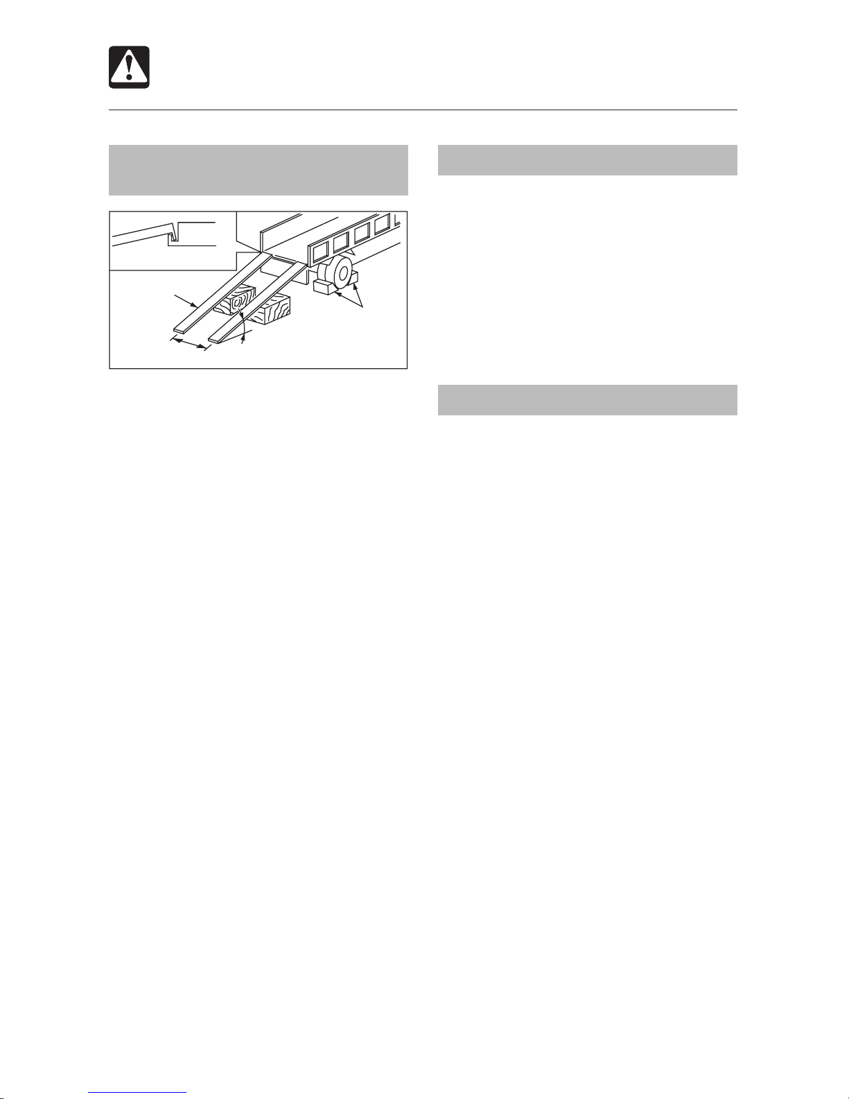
Load and unload the machine
safely
The machine may roll or tip over or fall while
loading or unloading it. Take the following
precautions:
Select a firm, level surface and keep
sufficient distance from road shoulders.
Use loading ramps of adequate strength
and size. Maintain the slope of loading
ramps to 15 degrees or less.
Secure the ramps to the truck bed.
Keep the truck bed and loading ramps
clean of oil, clay, ice, snow, and other
materials that can become slippery. Clean
the tracks.
Block the transport vehicle so it cannot
move.
Use a signal person when loading and
unloading the machine, and travel slowly
in first gear (low speed).
Never change course on the ramp.
Do not turn on the ramps. The machine
may tip over.
Block both tracks and secure the machine
to the truck bed with load binders.
Transport the machine safely
Know and follow the safety rules, vehicle
code and traffic laws when transporting
the machine.
Consider the length, width, height and
weight of the truck with the machine
loaded on it when determining the best
route.
Hoisting the machine safely
Know and use correct crane signals.
Inspect the hoisting equipment daily for
damaged or missing parts.
When hoisting, use a wire rope with
sufficient strength with respect to the
machine’s weight.
Do not hoist the machine with an operator
on it.
When hoisting, hoist slowly so that the
machine does not tip.
Keep all other persons out of the area
when hoisting. Do not move the machine
over the heads of the persons.
Do not hoist with the machine in a position
other than the one described in the
procedure below. Doing so is dangerous
because it may result in the machine
losing its balance.
Refer to the section titled “Hoisting the
Machine” for further details.
Fasten to the suspension fitting
Ramp
15° or less
Distance between ramps
Stopper
Page 30
SAFETY
28
Maintenance Precautions
Attach a “DO NOT OPERATE” tag
Severe injury could result if an unauthorized
person starts the engine or touches controls
during inspection or maintenance.
Stop the engine and remove the key
before performing maintenance.
Attach a “DO NOT OPERATE” tag to the
ignition switch or control lever.
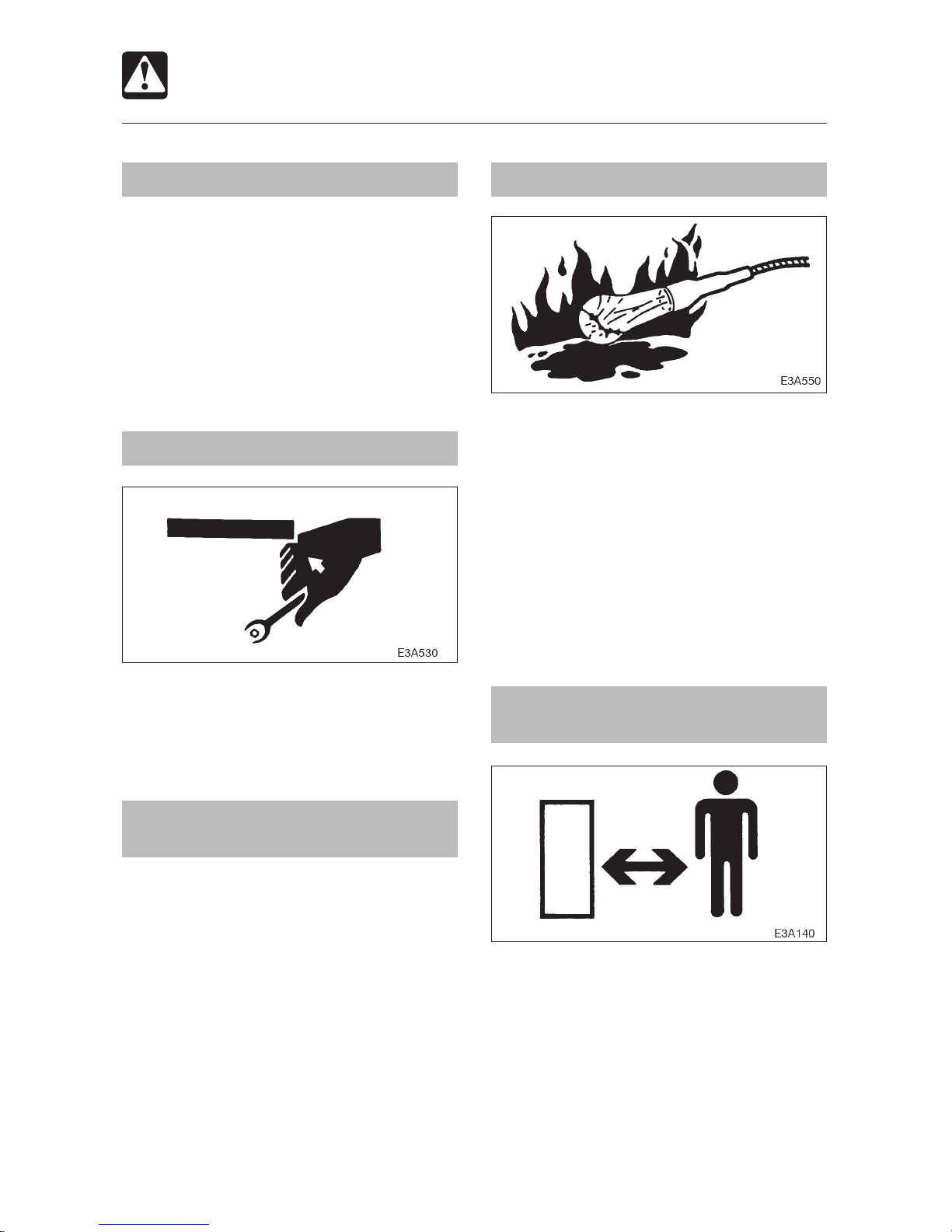
Use the correct tools
Do not use damaged or weakened tools, or
tools designed for other purposes. Use tools
suited for the operation.
Replace important safety parts
periodically
Replace fuel hoses periodically. Fuel
hoses become weaker over time, even if
they appear to be in good condition.
Replace important safety parts whenever
an malfunction is found, even if it is before
the normal time for replacement.
Refer to the section titled “Important
Parts” for further details.
Anti-explosive lighting
Use anti-explosive electrical fixtures and
lights when inspecting fuel, oil, coolant,
battery fluid, etc. If lighting that is not antiexplosive breaks, the substance could ignite,
resulting in serious injury or death.
Do not allow unauthorized
personnel in the work area
Do not allow unauthorized personnel in the
work area. Chips or other debris can fly off
machine parts when grinding, welding or
using a hammer.
Page 31

29
SAFETY
Maintenance Precautions
Prepare the work area
Select a firm, level work area. Make sure
there is adequate light and, if indoors,
ventilation.
Clear obstacles and dangerous objects.
Eliminate slippery areas.
Always clean the machine
Clean the machine before performing
maintenance.
Stop the engine before washing the
machine. Cover the electrical parts so that
water cannot enter. Water on electrical
parts could cause short-circuits or
malfunctions. Do not use water or steam
to wash the battery, electronic control
components, sensors, connectors or the
operator’s compartment.
Stop the engine before performing
maintenance
Avoid lubrication or mechanical
adjustments with the machine in motion or
with the engine running while stationary.
If maintenance must be performed with
the engine running, always work as a twoperson team, with one person sitting in
the operator’s seat while the other works
on the machine.
• When performing maintenance, be sure
to keep your body and clothing away
from moving parts.
Stay clear of moving parts
Stay clear of all rotating and moving parts.
Wrapping or entanglement may result in
serious injury or death.
Keep hands, clothing and tools away from
the rotating fan and running fan belts.
Page 32

SAFETY
30
Maintenance Precautions
Securely block the machine or any
component that may fall
Before performing maintenance or repairs
under the machine, set the bucket against
the ground or in the lowermost position.
Securely block the tracks.
If you must work beneath the raised
machine or equipment, always use lift
arm stop, jack-stands or other rigid and
stable supports. Never get under the
machine or working equipment if they are
not sufficiently supported. This procedure
is especially important when working on
hydraulic cylinders.
Securely block the raised lift arms
If you must work beneath the raised lift
arms, securely engage the lift arm stop.
Never get under the lift arms and bucket if
they are not sufficiently supported.
Disconnecting or loosening any hydraulic
line, hose, fitting or component or a parts
failure can cause the lift arms to drop.
Service the lift arm stop if damaged or if
parts are missing. Using a damaged lift
arm stop or with missing parts can cause
the lift arms to drop, causing injury or
death.
Secure the rear door when
opened
Be sure to secure the rear door when opening
it. Do not open the rear door on slopes or in
strong wind.
Cautions on tilting up the ROPS
Raising or lowering the ROPS while the
engine is running may cause the machine
to move, and cause serious injury or
death. Lower the working equipment to
the ground and stop the engine before
raising or lowering the ROPS.
When the ROPS is tilted up, support it
firmly with the stop to prevent it from
falling.
Place heavy objects in a stable
position
When removing or installing the bucket or
attachment, place it in a stable position so
that it does not tip over.
T7A031
Page 33

31
SAFETY
Maintenance Precautions
Use caution when fueling
Do not smoke or permit open flames while
fueling or near fueling operations.
Never remove the fuel cap or refuel with
the engine running or hot. Never allow fuel
to spill on hot machine components.
Maintain control of the fuel filler nozzle
when filling the tank.
Do not fill the fuel tank to capacity. Allow
room for expansion.
Clean up spilled fuel immediately.
Tighten the fuel tank cap securely. If the
fuel cap is lost, replace it only with the
original manufacturer’s approved cap.
Use of a non-approved cap without proper
venting may result in pressurization of the
tank.
Never use fuel for cleaning purposes.
Use the correct fuel grade for the operating
season.
Handling of hoses
Fuel, oil and hydraulic fluid leaks can cause
a fire.
Do not twist, bend or hit the hoses.
Never use twisted, bent or cracked hoses,
tubes and pipes. They may burst.
Retighten loose connections.
Be careful with hot and
pressurized components
Stop the engine and allow the machine to
cool down before performing inspection and
maintenance.
The engine, muffler, radiator, hydraulic
lines, sliding parts and many other parts
of the machine are hot after the engine is
stopped. Touching these parts will cause
burns.
The engine coolant, oil and hydraulic fluid
are also hot and under high pressure.
Be careful when loosening caps and
plugs. Working on the machine under
these conditions could result in burns or
injuries due to the hot oil spraying out.
Page 34

SAFETY
32
Maintenance Precautions
Be careful with hot cooling
systems
Do not remove the radiator cap or drain plugs
when the coolant is hot. Stop the engine, let
the engine and radiator cool, and loosen the
radiator cap or drain plugs slowly.
Be careful with fluids under
pressure
Pressure can be retained in the hydraulic
circuit long after the engine has been shut
down.
Release all pressure before working on
the hydraulic system.
Hydraulic fluid under pressure can
penetrate the skin and eyes and cause
injury, blindness or death. Fluid escaping
from a small hole can be almost invisible.
Wear safety goggles and heavy gloves,
and use a piece of cardboard or wood to
search for suspected leaks.
If fluid is injected into the skin, it must be
removed within a few hours by a doctor
familiar with this type of injury.
Release all pressure before
working on the hydraulic system
Oil may spray out if caps or filters are removed
or pipes disconnected before releasing the
pressure in the hydraulic system.
When removing plugs and screws and
disconnecting hoses, stand to the side
and loosen slowly to gradually release the
internal pressure before removing.
Be careful with grease under
pressure
The track adjuster contains highly pressurized
grease. If the tension is adjusted without
following the prescribed procedure, the
grease discharge valve may fly off, resulting
in injury.
Loosen the grease discharge valve
slowly.
Do not put your face, arms, legs or body
in front of the grease discharge valve.
If no grease is expelled when grease
discharge valve is loosened, there is a
problem. Contact your nearest service
outlet for repairs. DO NOT disassemble,
because this is very dangerous.
Page 35
33
SAFETY
Maintenance Precautions
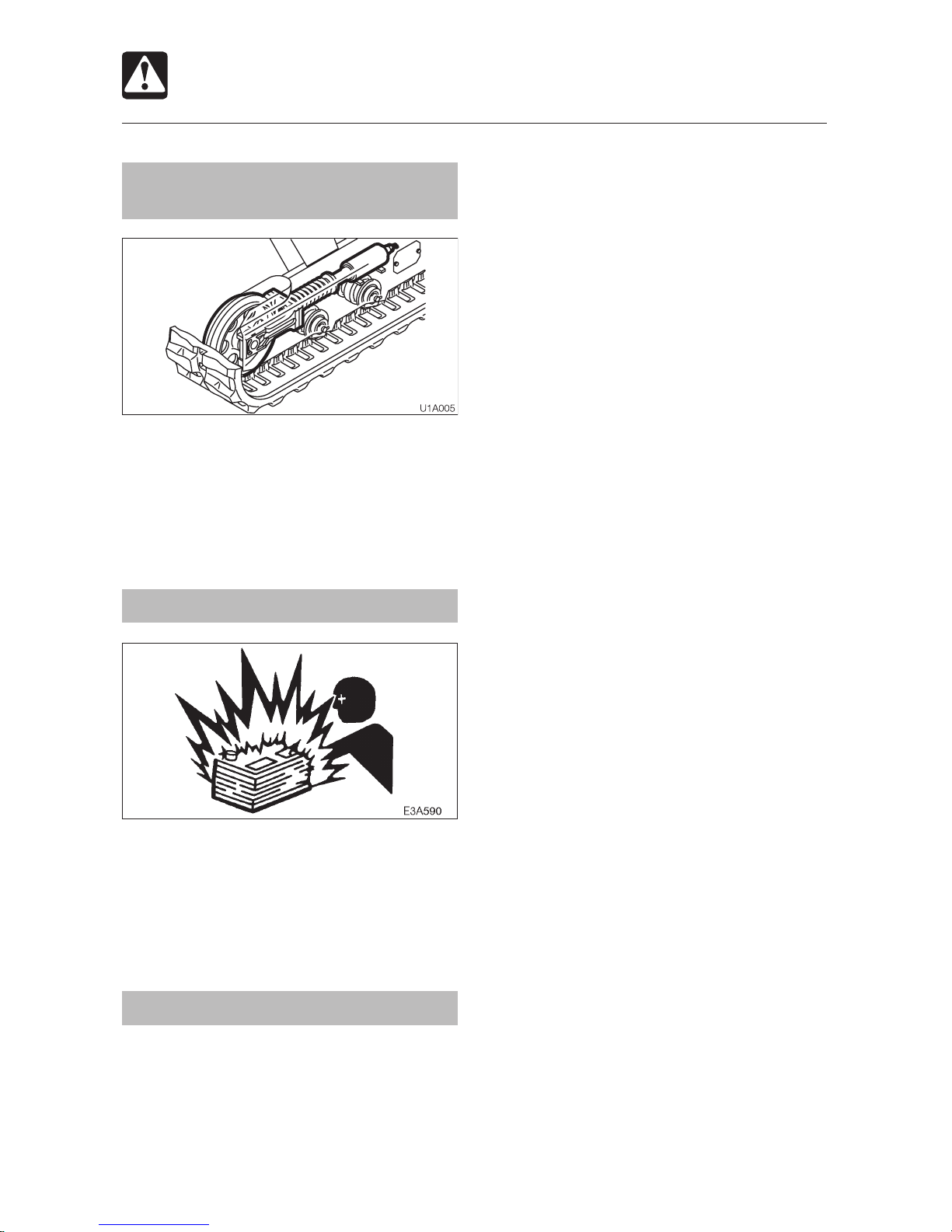
Never disassemble the track
adjuster
There is very strong spring contained in
the track adjuster. If the track adjuster is
accidentally disassembled, the spring can
pop out, resulting in serious injury never
disassemble the track adjuster.
Disconnect the battery
Disconnect the battery before working on
the electrical system or doing any welding.
Remove the negative (–) battery cable first.
When reconnecting the battery, connect the
negative (–) battery cable last.
Avoid battery hazards
Batteries contain sulfuric acid, which will
damage eyes and skin on contact.
• If acid contacts eyes, flush immediately
with clean water and get prompt medical
attention.
• If acid is accidentally swallowed, drink
large quantities of water or milk and call
a physician immediately.
• If acid contacts skin or clothing, wash
off immediately with clean water.
Wear safety glasses and gloves when
working with batteries.
Batteries generate flammable and
explosive gases. Keep arcs, sparks,
flames and lighted tobacco away.
Use a flashlight to check battery electrolyte
level.
Stop the engine and shut off electrical
equipment while inspecting or handling
the battery.
Do not short circuit the battery posts with
metal items.
Always unfasten the negative (–) battery
cable first when disconnecting the battery
cable. Always connect the negative
(–) battery cable last when fastening the
battery cable.
Loose battery terminals may result in
sparks. Be sure to fasten terminals
tightly.
Make sure the vent caps are tightened
securely.
Do not charge a battery or jump-start the
engine if the battery is frozen. Warm to
15°C (60°F) or the battery may explode.
Do not use the battery when the fluid
level is below the lower level. Doing so
will hasten the deterioration of the internal
portions of the battery and shorten the
battery life, and can also cause rupturing
(or an explosion).
Do not fill the battery above the upper
level. Doing so could cause the fluid to
leak, contact and damage the skin, or
cause parts to corrode.
Page 36

SAFETY
34
Maintenance Precautions
Have a Gehl technician repair
weld cracks or other damage
If welding must be performed, make sure that
it is done by a qualified person in a properly
equipped workplace. To prevent any part
from breaking down or be being damaged
due to overcurrent or sparks, observe the
following.
Disconnect the wiring from the battery
before doing electric welding.
Do not continuously apply 200V or more.
The earth ground must be connected
within one meter from the welding
section. Do not connect the earth ground
near to an electronically controlled device/
instrument or connectors.
Make sure that there are no seals or
bearings between the welding section
and the earth ground.
Do not connect the earth ground around
the pins for working equipment or
hydraulic cylinders.
When welding is to be done on the
machine body, disconnect the connectors
for the electronically controlled devices
before working.
Safety signs
Keep all safety signs clean and legible.
Replace all missing, illegible or damaged
safety and warning signs.
Vibrations to which the operator is
subjected
According to the results of the tests carried
out to determine the vibrations transmitted
to the operator by the machine, the upper
limbs are subjected to vibrations lower than
2.5 m (8.2 ft.) / s
2
, while the seated part of the
body is subjected to vibrations lower than
0.5 m (1.64 ft.) / s
2
.
Checks after maintenance
Gradually raise the engine speed from low
idle to maximum speed and check that
no oil or water is leaking from serviced
parts.
Move the controls and check that the
machine is operating properly.
Disposing of wastes
Pour waste fluids from the machine into
containers. Disposing of fluids improperly
destroys the environment.
Follow the prescribed regulations when
disposing of oil, fuel, engine coolant,
refrigerant, solvents, filters, batteries and
other harmful substances.
Handling of poisonous chemicals
Poisonous chemicals will cause serious
injury if directly contacted.
Poisonous chemistry used in this machine
includes grease, battery solution, coolant,
paint and adhesive agent.
Page 37

35
SAFETY
Safety Signs (Decals)
The following safety signs (decals) have been placed on the machine in the areas indicated.
They are intended for the personal safety of the operator, and co-workers. Please take this
manual, walk around the machine and note the content and location of these safety signs.
Review these signs and the operating instructions in this manual with all machine operators.
Keep the safety signs legible. If they are not, obtain replacements from your Gehl dealer.
Page 38

SAFETY
36
Safety Signs (Decals)
Page 39

37
SAFETY
Safety Signs (Decals)
Page 40

SAFETY
38
Safety Signs (Decals)
Page 41

39
Names of Components ..................................40
Doors and Covers ...........................................42
Seat and Seat Belt ..........................................48
Instrument Panel .............................................52
Switches ...........................................................54
Levers and Pedals ...........................................59
Accessories .....................................................61
CONTROLS
Page 42

CONTROLS
40
Names of Components
1. Tail light
2. Hydraulic tank
3. ROPS / FOPS
4. Safety bar
5. Front light
6. Lift arm stop
7. Left control lever
8. Auxiliary hydraulic lines
9. Lift arm
10. Bucket cylinder
11. Bucket
12. Fuel filler cap
13. Arm cylinder
14. Travel motor
15. Rubber track
16. Track roller
17. Idler
T9B006
2 3 4 5 6 7 8
10
12
13
14
15
16
17
1
9
11
Page 43

41
CONTROLS
Names of Components
1. Left control lever
2. Travel speed button
3. Slider switch (for auxiliary hydraulic)
4. Detent mode switch
(for auxiliary hydraulic switches)
5. Flow selector switch (2-way
1-way)
6. Front wiper switch (option)
7. Rear wiper switch (option)
8. Safety bar
9. Seat
10. Auxiliary hydraulic buttons
11. Instrument panel
12. Float button
13. Horn button
14. Right control lever
15. Ignition switch
16. High-flow switch (option)
17. Throttle lever
18. Throttle pedal
19. Front light switch
20. Tail light switch
21. Multifunction buttons
U1B0013
3
2
8
10
11
1218
9
1
4
5
6
7
10
21
13
14
15
16
17
19
20
21
21
Page 44

CONTROLS
42
Ignition Key
The Ignition key is used not only to start and
stop the engine, but also to lock and unlock
the following places:
Fuel filler cap
Engine hood
Cab door
Manual storage
Doors and Covers
E4B003
Cab Door < CTL55 >
WARNING
When mounting and dismounting the
cab, first open the door fully to the
stopped position and check that it
does not move.
When opening and closing the door,
grasp the handle securely and move
the door slowly. Opening the door
suddenly could result in it hitting your
head, or your hands or feet could get
caught.
Preparation before Opening and Closing
the Cab Door
1. Park the machine on a level surface and
stop the engine.
2. Raise the safety bar.
Lock and unlock
1. Insert and turn the ignition key.
Opening
1. Turn the handle (2) clockwise and open
the door fully.
To open the door from inside the cab:
1. Turn the handle (2) counterclockwise and
open the door fully.
Closing
1. Grasp the handle (2) or (3) and slowly
close the door.
T3B004
1
T3B005
T3B006
2
3
3
Page 45

43
CONTROLS
Doors and Covers
Side Window < CTL55 >
1. Grasp the catch (8), unlock it and open the
side window.
2. To close the side window, close it until a
click is heard.
8
T9C010
Page 46

CONTROLS
44
Rear Door
CAUTION
When opening the rear door, open it
firmly to the locked position.
When opening and closing the rear
door, be careful not to get your hands
or other parts of your body caught.
Opening
1. Open the engine hood.
2. Lift the lever (1) and open the rear door
(2).
3. Release the stay (3), then insert and secure
it into the stay hole of the rear door (2).
Closing
1. Support the rear door (2) by hand, remove
stay (3), and secure it in the original
position.
2. Close the rear door (2) and press it until a
click is heard at the front.
Doors and Covers
Engine Hood
WARNING
Before opening the engine hood, be sure
to stop the engine. If your hands or tools
get caught in the fan or fan belt while the
engine is running they may be severely
injured.
Opening
1. Insert the ignition key and turn it
counterclockwise to unlock the engine
hood (1).
2. Remove the key and pull the lever (2)
backward.
3. Lift the engine hood (1).
Closing
1. Close the engine hood and press it down
until a click is heard at the front.
2. Insert the ignition key and turn it clockwise
to lock the engine hood.
T8B003
1
2
T7B003
1
2
3
Page 47

45
CONTROLS
Emergency Exit
If you become trapped inside the cab,
remove the rear window to get out.
There are two ways to remove the rear
window:
— In case of emergency
Kick out the rear window. Note that the
glass may break. Be careful not to be
injured.
— In case of need
1. Pull off ring (A) and remove the tip of the
rubber wedge.
2. Grasp the tip, pull, and remove the
entire rubber wedge.
3. Pull inside knob (B).
Doors and Covers
E X I T
T8B001
A
B
Page 48

CONTROLS
46
Doors and Covers
Lift Arm Stop
WARNING
If you must work beneath the raised
lift arms, securely engage the lift arm
stop. Never get under the lift arms
and bucket if they are not sufficiently
supported.
Service the lift arm stop if damaged or
if parts are missing. Using a damaged
lift arm stop or with missing parts can
cause the lift arms to drop, causing
injury or death.
Maintenance and service work can be done
with the lift arms lowered. If the lift arms
are raised, use the following procedures to
engage and disengage an approved lift arm
stop.
Engagement
1. Park the machine on level ground and
remove the bucket or attachment.
2. Lower the lift arms to the ground and stop
the engine.
3. Align the hook (4) on the tip of the locking
pin (1) with the locking pin.
4. Support the lift arm stop (2) by hand and
pull out the locking pin (1).
5. Check that the spring (3) moves freely
(i.e., is disengaged from the hook (5)) and
place the lift arm stop (2) on the cylinder.
6. Sit in the seat, fasten the seat belt, start
the engine and lower the safety bar.
7. Raise the lift arms slowly until the lift arm
stop (2) drops onto the cylinder rod.
8. Lower the lift arms slowly until the lift arm
stop is held between the lift arm and the
end of the cylinder tube.
9. Stop the engine.
10. Install the locking pin (1) into the rear of
the lift arm stop (2) below the cylinder
rod.
11. To prevent the locking pin (1) from falling
off, set the hook (4) at a right angle to the
locking pin.
T9B002
Page 49

47
CONTROLS
Doors and Covers
Disengagement
1. Align the hook (4) on the tip of the locking
pin (1) with the locking pin.
2. Pull out the locking pin (1) from the lift arm
stop (2).
3. Hook the end part of the spring (3) onto
the hook (5) of the lift arm stop (2).
4. Sit in the seat, fasten the seat belt, start
the engine and lower the safety bar.
5. Raise the lift arms slowly until the spring
(3) will lift the lift arm stop (2) off the cylinder
rod.
6. Lower the lift arms slowly to the ground
and stop the engine.
7. Raise the lift arm stop (2) into storage
position and insert the locking pin (1)
through lift arm stop and bracket.
8. To prevent the locking pin (1) from falling
off, set the hook (4) at a right angle to the
locking pin.
Fuel Filler Cap
WARNING
Do not smoke or permit open
flames while fueling or near fueling
operations.
Supply fuel in a well ventilated place
and with the engine stopped.
Clean up spilled fuel immediately.
Do not fill the fuel tank to capacity.
Allow room for expansion.
Tighten the fuel filler cap securely.
Opening
1. Open the key cover, insert the key and
turn it counterclockwise to unlock the fuel
cap.
2. Turn the fuel cap counterclockwise and
remove it.
Closing
1. Set the fuel cap in place and turn it
clockwise.
2. Turn the key clockwise to lock the fuel
cap, then remove the key.
T7B005E
Close Open
Page 50

CONTROLS
48
Seat and Seat Belt
Seat < CTL55 >
WARNING
Adjust, secure and latch the operator’s
seat.
(A) Seatback angle adjustment
1. Raise your torso, and sit down firmly in
the seat.
2. Pull on lever (1) to use the force of the
springs in the seatback to adjust the
reclining angle. Release the lever (1) at the
desired angle and the seatback will be
locked in that position.
Adjustment range ..................... 15 deg.
(B) Fore-and-aft adjustment
1. Pull on lever (2) and slide the seat rearward
or forward to bring it to the optimum
position for operating the machine.
2. Release the lever (2) at the desired position
and the seat will be locked there.
Adjustment range: 130 mm (5.1 in.)
(C) Weight adjustment
1. Pull on and shift the lever (3) to right side
or left side, to adjust the seat suspension
according to the operator’s weight.
• Right .............Light operator
• Middle ..........Medium weight operator
• Left ...............Heavy operator
Page 51

49
CONTROLS
Seat Belt < CTL55 >
CAUTION
Always fasten the seat belt securely
before starting the engine.
Fastening the seat belt
1. Adjust the seat to the optimum position
for operating, raise your torso, and sit
back firmly into the seat.
2. Pull on adjuster (A) in the manner shown in
the diagram to adjust the seat belt to the
desired length.
3. Make sure that the belt is not twisted, and
then insert the tongue plate (B) into the
buckle (C) of the seat belt until you hear a
clicking sound as it locks in place.
4. Pull the belt until you can feel the pressure
on your pelvis with the belt firmly in
place.
Seat and Seat Belt
C4C010
A
90°
C4C011
B
C
Page 52

CONTROLS
50
Seat and Seat Belt
Seat < CTL65 / CTL75 / CTL85 >
WARNING
Adjust, secure and latch the operator’s
seat.
(A) Seatback angle adjustment
WARNING
Do not set the seat back to its maximum
reclining position and slide the seat
backwards at the same time. Doing
so may break the rear window glass,
resulting in injury.
Be careful not to allow the force of the
spring to bring the seat back sharply
forward.
1. Raise your torso, and sit down firmly in
the seat.
2. Pull on lever (1) to use the force of the
springs in the seatback to adjust the
reclining angle. Release the lever (1) at the
desired angle and the seatback will be
locked in that position.
(B) Fore-and-aft adjustment
1. Pull on lever (2) and slide the seat rearward
or forward to bring it to the optimum
position for operating the machine.
2. Release the lever (2) at the desired position
and the seat will be locked there.
Adjustment range: 15 steps,150 mm (5.9
in.)
(C) Weight adjustment
1. Turn handle (3) until the indicator (4) will
show the operator’s weight .
May be set to any value 10 kg steps, from
50 to 130 kg (110 to 287 lbs.)
(D) Vertical adjustment
Upward—
Lift the seat to first or second position
click-stop.
Downward—
First lift the seat to highest position, then the
seat can be lowered to lowest position.
(E) Headrest adjustment (Option)
The position of the headrest can be adjusted
in the vertical and front/rear directions.
1. To adjust in the vertical direction, grasp
the headrest with both hands and move
it upward or downward.
2. To adjust in the front/rear direction, grasp
the headrest with both hands and move it
forward or rearward.
Page 53

51
CONTROLS
Seat and Seat Belt
Seat Belt < CTL65 / CTL75 / CTL85 >
CAUTION
Always fasten the seat belt securely
before starting the engine.
Fastening the seat belt
1. Adjust the seat to the optimum position
for operating, raise your torso, and sit
back firmly into the seat.
2. Pull the seat belt to the desired length.
3. Make sure that the belt is not twisted and
then insert the tongue plate (A) into the
buckle (B) of the seat belt until you hear a
clicking sound as it locks in place.
Releasing the seat belt
To remove the seat belt, simply press the
button (C) located on the buckle.
The seat belt is automatically retracted.
E4B023
B
A
E4B024
C
Page 54

CONTROLS
52
Instrument Panel
Warning Lamps
IMPORTANT: If a warning lamp flashes
and an alarm is sounded, stop all
operations immediately and inspect and
maintain the appropriate parts.
Refer to page 162, “Troubleshooting.”
1. Engine Oil Pressure Warning Lamp
This lamp flashes and an
alarm is sounded if the
lubricant oil pressure drops
abnormally while the engine
is running.
2. Coolant Temperature Warning Lamp
This lamp flashes and an
alarm is sounded if the
engine coolant temperature
rises abnormally while the
engine is running.
3. Battery Charge Warning Lamp
This lamp flashes and
an alarm is sounded if
a problem arises in the
charging system while the
engine is running.
4. Air Cleaner Warning Lamp
This lamp flashes and an
alarm is sounded if the air
cleaner filter is clogged
while the engine is running.
5. Pilot Line Filter Warning Lamp
This lamp flashes and an
alarm is sounded if the pilot
line filter is clogged while
the engine is running. This
lamp may flashes directly after the engine
in started in cold weather. This is not a
malfunction. The lamp will turn off as the
engine warms up.
C4B012
G4B010
T7B008
C4B030
C4B031
Page 55

53
CONTROLS
Instrument Panel
Indicators
6. Glow Lamp
This lamp turns off when
engine preheating is
completed.
7. Travel Speed Lamp
This lamp lights when the
travel speed button is set to
2nd (high speed).
Meters
8. Hour meter
This displays the total engine
running time in hours.
The rightmost digit indicates
tenths of hours (6 minutes).
Set the inspection and
maintenance intervals according to the time
displayed on the hour-meter.
9. Coolant Temperature Gauge
This gauge indicates the
temperature of the engine
coolant.
The needle should be within
the green range during
machine operation.
The red range indicates overheating.
10. Fuel Gauge
This gauge indicates the
amount of fuel in the tank.
Be sure to top off the tank
before running out of fuel.
C4B013
C4B014
L3B019
L3B020
L3B021
Engine Fault Warning Lamp
< CTL55 / CTL65 / CTL75 >
IMPORTANT: If the lamp flashes, check
the flashing pattern, stop the engine and
then contact a Gehl sales or service outlet
for help. Do not run the engine while the
lamp is flashing. Otherwise, the specified
engine performance cannot be obtained
or more serious problem can occur.
When the ignition switch is turned to the ON
position, the lamp lights up and stays on for
2 seconds and then goes out.
If a problem arises in the engine or controls,
the lamp starts flashing, with the flashing
pattern corresponding to the type of
problem.
Page 56

CONTROLS
54
Switches
Float Button
WARNING
Make sure the bucket is lowered to
the ground before putting the lift arms
in the Float mode. Putting the lift arms
in the Float mode while they are raised
will cause the bucket to fall and is
extremely dangerous.
Do not drive the loader forward with
the lift arms in the Float mode.
This button sets the lift arms to the Float
mode. The lift arms are put to the Float
mode while this button is pressed in. When
the button is released, the Float mode is
canceled.
Setting the arm float to the detent mode
To set to the detent mode, press and hold the
arm float button and move the right control
lever forward once. To turn off the detent
mode, move the right control lever rearward.
When in the Float mode, the bucket can
follow the contour of the ground without
movement of the control lever.
Ignition Switch
IMPORTANT: Do not repeatedly switch
the key from OFF to ON and ON to OFF
over a short period. Doing so will cause
engine breakdown.
PREHEAT ....... Position for preheating the
engine.
OFF ................ Position for stopping the
engine and inserting and
removing the key.
ON .................. Position in which the engine
is running. In this position, all
the electrical equipment is
functional.
START ............ Position for starting the engine.
When the key is released, the
switch automatically returns
to the ON position.
Horn Button
Press the right button on the right control
lever to blow the horn.
Page 57

55
MEMO
Multifunction Buttons
These buttons are used to operate various
optional functions.
1. Turn the cap (1) counterclockwise and
remove it.
2. To install the female connector or the cap
(1), align the notches and turn it clockwise
to tighten.
<14P connector M>
HDB34-18-14PN-059
Total max. working current: 20A
Max. working current at each terminal:
13A
U1L008
C
D
E
14P Connector M
F
J
A
B
C
D
E
F
G
H
J
K
L
ACC
M
N
P
U1L009
1
Page 58

CONTROLS
56
Switches
Auxiliary Hydraulic Switches
Auxiliary Hydraulic Buttons (A), (B)
Press these buttons to control the flow of the
oil in the auxiliary hydraulic circuit.
(A) .............Hydraulic oil flows to auxiliary
hydraulic line (a)
(B) .............Hydraulic oil flows to auxiliary
hydraulic line (b)
The button turns on the flow when it is
pressed, and turns off the flow when it is
released.
When one-way flow is selected by turning
on the flow selector switch (C), the
auxiliary hydraulic button only functions
when button (A) is pressed.
Refer to page 81 “Operating the Auxiliary
Hydraulics”.
Slider Switch
(Proportional control)
Proportional control allows for slow-to-fast
movement of auxiliary functions.
Example: If you move the slider switch
half way, the auxiliary function will move at
approximately one-half speed.
Move this switch to control the flow of the oil
in the first auxiliary hydraulic lines.
Flow Selector Switch (C)
The flow of the auxiliary hydraulic system
(lines (a) and (b)) can be set to either one-way
or two-way flow. When the switch is pressed,
the flow switches from two-way to one-way
and the built-in lamp (green) lights. When
pressed again, the flow switches from oneway back to two-way and the lamp turns off.
OFF(O) ......Two-way flow
ON ( I ) .....One-way flow
The oil in line (b) returns to the
hydraulic tank.
T9B012
Page 59

57
CONTROLS
Switches
High-Flow Switch (E) - (If equipped)
This switch controls the ON / OFF function of
the high-flow auxiliary hydraulics.
Press this switch to activate the high-flow
hydraulics and the hydraulic flow switches
from two-way to one-way and the builtin lamp and flow selector switch lamp
(green) come on. Press this switch again to
deactivate the high-flow hydraulics and the
hydraulic flow switches from one-way back
to two-way and the lamps go out.
Refer to page 63, “High-Flow Hydraulic
System”.
O .........OFF
I ..........ON
Detent Mode Switch (D)
This switch changes the function of auxiliary
hydraulic button (A). Normally auxiliary
hydraulic flow is on while button (A) is pressed
and turns off when it is released. If pressed
again after pressing this switch, then auxiliary
hydraulic button (A) turns on and stays on
when it is pressed, and only turns off when it
is pressed again. The built-in lamp (orange)
lights when the switch is on. Thus there is no
need to hold the switch in. When this switch
is pressed again, the function of the auxiliary
hydraulic switch returns to normal and the
lamp turns off.
T9B0151
Page 60

CONTROLS
58
Travel Speed Button
Press this button to set the travel speed to
2nd speed (high speed) while travel speed
lamp lights. Press again to return to 1st
speed (low speed) and travel speed lamp
turns off.
Travel speed always begins in 1st speed
when starting the engine.
Refer to page 53, “Travel Speed Lamp.”
Light Switches
When this switch is turned on while the
ignition switch is ON, the lights turn on as
follows:
Front light switch
O ...............Off
I ................Instrument lights and front lights
turn on.
Tail light switch
O ...............Off
I ................Tail lights turn on.
Wiper Switches (Option)
IMPORTANT: If no washer fluid is
discharged, do not operate the washer.
Doing so may damage the pump.
IMPORTANT: Operating the wiper with no
moisture on the windshield will scratch
the glass. Apply water or washer fluid
when operating the wiper.
IMPORTANT: In cold seasons, the wiper
blade may freeze to the glass. Operating
the wiper forcibly may damage the wiper
motor.
Front wiper switch
O ...............Off
I ................Wiper operates.
PUSH .......Washer fluid is squirted from the
nozzle while pressed, and stops
when released.
Rear wiper switch
O ...............Off
I ................Wiper operates.
PUSH .......Washer fluid is squirted from the
nozzle while pressed, and stops
when released.
Switches
L3B028
L3B029
PUSH
Page 61

59
CONTROLS
Safety Bar
WARNING
Before leaving the operator’s seat,
raise the safety bar to engage the lock
and stop the engine.
If any controls are touched accidentally
when the safety bar is lowered, the
machine will move suddenly, and
cause serious injury or death.
Be careful not to touch the control
levers and pedal when lowering or
raising the safety bar.
This device is for locking the control levers,
pedal and selector, detent mode and highflow switches.
When the safety bar is lifted, the levers, pedal
and switches are locked.
Throttle Lever
This lever controls the engine speed.
(A) ............Low idle
(B) ...........Maximum speed
Throttle Pedal
This pedal controls the engine speed.
(A) ............Low idle
(B) ...........Maximum speed
Levers and Pedals
T7B015
U1B014
B
A
Page 62

CONTROLS
60
Left Control Lever
Use this lever to move forward and rearward
and to change directions.
Refer to page 74, “Lever Pattern.”
Refer to page 77, “Operating the Left Control
Lever.”
Levers and Pedals
Right Control Lever
WARNING
Be sure to check which pattern of lever
control arrangement you are operating
with before beginning operations.
Use this lever to operate the lift arms and
bucket.
Refer to page 74, “Lever Pattern.”
Refer to page 80, “Operating the Right
Control Lever.”
Page 63

61
CONTROLS
Accessories
Interior Light (Option)
IMPORTANT: The battery charge will
decrease if the interior light is left on
for long periods of time with the engine
stopped. Turn the light off when leaving
the machine.
O .........Off
I ..........On
O
I
T7B0271
Page 64

CONTROLS
62
Accessories
Auxiliary Hydraulic Lines
WARNING
Oil may spray out if caps or filters are
removed or pipes disconnected before
releasing the pressure in the hydraulic
system.
• When removing plugs or
disconnecting hoses, release the
internal pressure before removing.
Hydraulic fluid, tubes, fittings and quick
couplers can get hot when running
machine and attachments.
Be careful when connecting and
disconnecting quick couplers.
These lines deliver the hydraulic oil necessary
for operating other attachments.
Auxiliary hydraulic flow rate and rated
pressure:
Flow Rate ...............
CTL55: 57 L/min (15.1 US gpm)
CTL65: 70 L/min (18.4 US gpm)
CTL75: 75 L/min (19.8 US gpm)
CTL85: 89 L/min (23.4 US gpm)
Rated Pressure ........ 20.6 MPa (2987 psi)
Quick-Couplers
Connecting: Remove dirt or debris from
the surface of both the male and female
couplers, and from the outside diameter of
the male coupler. Visually check the couplers
for corrosion, cracks, damage or excessive
wear. If any of these conditions exist, the
coupler(s) must be replaced.
Install the male coupler into the female
coupler. Full connection is made when the
ball-release sleeve slides forward on the
female coupler.
Disconnecting: Hold the male coupler.
Retract the sleeve on the female coupler
until the couplers disconnect.
Releasing Residual Pressure
Connecting: Push the quick-couplers tightly
together and hold for five seconds; the
pressure is automatically released as the
couplers are installed.
Disconnecting: Push the quick-couplers
tightly together and hold for five seconds;
then retract the sleeve until the couplers
disconnect.
Connecting the Hydraulic Circuits
To connect attachment hydraulic lines, use
the following procedures:
1. Connect the attachment hydraulic lines to
ports (a) and (b).
When fitted with a hydraulic breaker:
a. Connect the return circuit to port (b)
and the supply circuit to port (a).
b. Turn on the flow selector switch.
Refer to page 56 “Flow Selector
Switch.”
Some attachments may have a case
drain, which needs to be the connected
to the small port (T).
2. When connecting is complete, purge air
from the hydraulic lines.
a. Start and run the engine at low idle with
no load for 10 minutes.
b. With the engine running at low idle,
operate the auxiliary hydraulics switch
repeatedly (approx. 10 times) to purge
air from the hydraulic lines.
c. Stop the engine and wait for more than
5 minutes until bubbles escape from
the hydraulic oil in the tank.
Page 65

63
CONTROLS
Accessories
IMPORTANT: Follow the procedures
for purging air as instructed by the
attachment manufacturer if specified to
do so.
3. Check for leaks.
High-flow Hydraulic System
(If Equipped)
The High-flow function provides additional
flow to the system to operate attachments
that require more hydraulic flow (EXAMPLE:
Cold planer).
This system can be used only for one-way
flow attachments.
Auxiliary hydraulic flow rate and rated
pressure:
Flow Rate ..................
CTL75: 138 L/min (36.3 US gpm)
CTL85: 152 L/min (40.1 US gpm)
Rated Pressure ..........20.6MPa (2987 psi)
1. Connect the attachment hydraulic lines to
ports (a) and (b).
Refer to page 62, “Connecting the
Hydraulic Circuits”.
Some attachments may have a case drain,
which need to be connected to the small
port (T).
2. Turn on the High-Flow switch (E) (green
light is ON).
3. Press the auxiliary hydraulic switch (A) or
slide the slider switch to the left side (A).
Refer to page 81, “Operating the Auxiliary
Hydraulics”.
Note: Running the high flow hydraulics
for extended periods of time could cause
damage to the hydraulics or other systems
of the machine due to overheating.
To prevent overheating and reduce the risk
of fire, the machine should be cleaned daily.
The standard cooling package is not
permitted for use in high airborne debris
applications such as mulching or land
clearing.
Operating attachments in these
environments could cause the warranty to
be denied.
IMPORTANT: Operation over long periods
with Detent mode switch pressed will
cause the hydraulic oil temperature to rise
and will shorten the life of the hydraulic
units.
T9B018
T9B0151
Page 66

64
MEMO
Page 67

65
MEMO
Page 68

66
MEMO
Page 69

67
MEMO
Page 70

68
Page 71

69
Before Starting Operation .............................70
Starting and Stopping the Engine ................71
Machine Operation .........................................74
Operating Procedures ....................................82
Parking the Machine ......................................90
Operating in Cold Weather ............................91
Using Rubber Tracks ......................................92
OPERATION
Page 72

OPERATION
70
Before Starting Operation
Mounting and Dismounting
WARNING
Do not jump on or off the machine.
Never attempt to mount or dismount a
moving machine.
When mounting and dismounting the
cab, first open the door fully to the
locked position and check that it does
not move (for machines with front
door).
Always face the access system and
maintain a three-point contact with the
handholds and steps while getting on
and off the machine. Keep steps and
platform clean.
Never use the control levers as hand
holds.
Walk-Around Inspection
Perform the walk-around inspection before
starting the engine the first time each day.
Perform the inspection as described under
“Maintenance - Walk-Around Inspection”
(pages 114 and 115).
Daily Inspection
Perform the daily inspection once a day
before starting the engine the first time each
day.
Perform the inspection as described under
“Maintenance - Daily Inspection” (pages
116 to 120).
T7D001
Page 73

71
OPERATION
Starting and Stopping the Engine
Before Starting the Engine
1. Adjust the seat for a comfortable operating
position.
2. Fasten the seat belt.
3. Check that the safety bar is in the locked
position.
4. Check that the control levers and pedal
are in the neutral position.
5. Insert the key into the ignition switch, turn
it to the ON position, then perform the
following inspection:
• All the warning lamps flash and an
alarm is sounded for 2 seconds. The
instruments also start functioning. After
2 seconds, only the battery charge
warning lamp (3) and engine oil pressure
warning lamp (1) flash, and the other
lamps turn off.
• Turn the light switch to check that the
front lights, tail lights and instruments
lights turn on.
• Check the fuel level.
If a lamp does not light or the alarm is not
sounded, the bulb may be burned out or
a wire may be damaged. Contact a Gehl
dealer for repairs.
T7B015
Page 74

OPERATION
72
Starting and Stopping the Engine
Starting the Engine
WARNING
Clear the area of all persons.
Sound horn to alert everyone around
the machine.
IMPORTANT: Do not run the starter motor
for more than 15 consecutive seconds.
If the engine fails to start, wait for 30
seconds to protect the battery, and then
try again to start the engine.
Normal Starting
1. Pull the throttle lever to the middle
position.
2. Turn the key to the START position and
start the engine.
3. Once the engine starts, release the key.
The key automatically returns to the ON
position.
4. Check that the warning lamps are off.
5. Return the throttle lever to idle position
and warm up the engine.
Refer to page 73, “Warming Up the
Engine.”
Starting in Cold Weather
1. Pull the throttle lever to the middle
position.
2. Turn the key to the PREHEAT position
and hold it there while the glow lamp is lit
(about 15 seconds /CTL85: 25 seconds).
3. After the glow lamp turns off, then turn the
key to the START position and start the
engine.
4. Once the engine starts, release the key.
The key automatically returns to the ON
position.
5. Check that the warning lamps are off.
6. Return the throttle lever to idle position
and warm up the engine.
Refer to page 73, “Warming Up the
Engine.”
Page 75

73
OPERATION
Starting and Stopping the Engine
Warming Up the Engine
IMPORTANT: Avoid racing the engine
until it is warmed up.
Do not warm up the engine for long
periods of time (20 minutes or more).
1. Return the throttle lever to idle position,
and idle the engine for about 5 minutes
with no load.
Stopping the Engine
IMPORTANT: Do not stop the engine
suddenly when operating with heavy
loads or at maximum speed. Doing so
may cause the engine to overheat or seize.
Never bring the engine to a sudden stop
except in the case of a true emergency.
1. Idle the engine for about 5 minutes to
gradually let it cool.
2. Turn the key to the OFF position to stop
the engine.
Page 76

OPERATION
74
Machine Operation
Lever Pattern
WARNING
Be careful to check which pattern of lever control arrangement you are operating
with before beginning operations.
The explanations in this manual are for this pattern.
Crawler Forward
Crawler Reverse
Left Spin Turn
Right Spin Turn
Left Pivot Turn
Right Pivot Turn
Right Pivot Turn Reverse
Left Pivot Turn Reverse
Lift Arm Lower
Lift Arm Raise
Bucket Rollback
Bucket Dump
Lift Arm Float
Neutral
N
Page 77

75
OPERATION
Machine Operation
Warming Up the Hydraulics
WARNING
Operating the working equipment without
warming up the hydraulics is dangerous,
because response will be slow and the
equipment may move in unexpected
ways. Be sure to sufficiently warm up the
hydraulics.
IMPORTANT: Do not operate the
levers suddenly when the hydraulic oil
temperature is below 20°C (68°F). The
proper hydraulic oil temperature during
operation is 50 to 80°C (122 to 176°F), but
if operations must be performed at lower
temperatures, heat up the hydraulic oil to
at least 20°C (68°F).
Normal Warm-up
1. Run the engine at medium speed for
about 5 minutes with no load.
2. Set the safety bar to the released position
and lift the bucket from the ground.
3. Extend and retract each of the cylinders
several times with no load.
4. Travel slowly forward and backward
several times.
Warming Up in Cold Weather
1. Perform the normal warm-up procedure.
2. Set the bucket cylinder at the stroke end
and keep it there.
Do not do this for more than 30 seconds.
3. Repeat step 2 until the bucket operating
speed is normal.
Page 78

OPERATION
76
Machine Operation
Inspection After Warm-up
After warming up the engine and hydraulic
oil, perform the checks and inspections
described below, and repair if there is a
problem.
1. Check that the warning lamps and
instruments are as follows:
• Are all the warning lamps off?
• Is the water temperature gauge needle
within the green range?
2. Check that there are no irregularities in the
exhaust color, sound and vibrations.
3. Set the safety bar to the locked position
and check that the control levers and
pedal are locked.
T7B015
Page 79

77
OPERATION
Machine Operation
Operating the Left Control Lever
WARNING
Never allow anyone to enter the turning
radius and machine path.
Signal your intention to move by
sounding the horn.
Traveling and turning should be
performed with the bucket cylinder fully
retracted and the bucket at a height of
approximately 30 cm (12 in.) from the
ground.
Avoid sudden stops, start or turns.
Do not raise the safety bar while
traveling. This is dangerous, because
raising the safety bar will cause the
parking brakes of the travel motors to
operate and apply the brakes abruptly.
Do not switch off the ignition switch
while traveling. Doing so will cause
sudden braking and is dangerous.
Before backing up, visually check for
safety to the rear. Backing up without
checking could result in contact with a
worker or obstacle.
If unavoidable while traveling, when
operating the working equipment, do
so with care.
Avoid crossing over obstacles whenever
possible. If you must do so, keep the
bucket close to the ground and travel
slowly. Never cross obstacles if they
will seriously tilt the machine (to an
angle of 15° or greater).
When traveling on rough terrain or
when carrying a load, lower the load
and travel slowly.
Remove any obstacles in the machine’s
path.
Use the left control lever to operate the
crawler tracks.
Return the left control lever to the neutral
position to stop the tracks.
1. Increase the engine speed.
2. Set the safety bar to the released
position.
3. Roll back the bucket fully and lift the bucket
to 30 cm (12 in.) above the ground.
T7A012E
30 cm
(12 in.)
Page 80

OPERATION
78
Machine Operation
Forward and Reverse Travel
To move forward:
Push the left control lever forward.
To move backward:
Pull the left control lever rearward.
Traveling in 2nd (High) Speed
Press the travel speed button on the left
control lever to switch to 2nd (high) speed,
and press it again to return to 1st speed (low
speed).
Pivot Turn
Turning to the left:
To turn forward to the left:
Tilt the left control lever forward to the
left.
To turn rearward to the left:
Tilt the left control lever rearward to the
right.
To turn to the right, operate the left control
lever in the opposite way.
Spin Turn
To spin left:
Tilt the left control lever to the left.
To spin right:
Tilt the left control lever to the right.
T7D0161
Page 81

79
OPERATION
Machine Operation
Stopping Travel
WARNING
Park the machine on firm, level ground
and apply the parking brake. If you
must park on a slope or incline, park
across the slope and block the machine
securely to prevent movement.
If any controls are touched accidentally
when the safety bar is lowered, the
machine will move suddenly, and may
cause serious injury or death.
CAUTION
Never bring the machine to a sudden stop
except in the case of a true emergency.
Stop as gently as possible.
1. Slowly set the left control lever to the
neutral position. The machine stops.
Braking is automatically applied by the
hydrostatic drive system when the left
control lever is returned to the neutral
position. Full braking is achieved when
the safety bar is raised.
Page 82

OPERATION
80
Machine Operation
Operating the Right Control Lever
WARNING
Be careful to check which pattern
of lever control arrangement you
are operating with before beginning
operations.
Make sure the bucket is lowered to
the ground before floating the lift
arms. Floating the lift arms while they
are raised will cause the bucket to fall
rapidly and is extremely dangerous.
Do not drive the loader forward with
the lift arms in Float position.
At times of combined operation of
bucket and lowering, tilting the lift
arms, continuation of the combined
operation after the bucket cylinder has
reached fall stroke will result in the lift
arms rising or stopping without going
lower. Be cautious of any unexpected
movement of the lift arms.
Use the right control lever to operate the lift
arms and bucket.
Return the right control lever to the neutral
position to stop the lift arms and bucket.
Set the safety bar to the released position.
Operating the Lift Arms
To lower the lift arms:
Push the right control lever forward.
To raise the lift arms:
Pull the right control lever rearward.
Operating the Bucket
To roll back:
Tilt the right control lever to the left.
To dump:
Tilt the right control lever to the right.
Operating the Lift Arms Float
To float the lift arms:
Press the float switch on the right control
lever.
Page 83

81
OPERATION
Machine Operation
Operating the Auxiliary Hydraulics
Use the auxiliary hydraulics to operate a
breaker, angle bucket or other approved
attachments.
Two methods of operation are permitted:
operation with the auxiliary hydraulic buttons,
and operation with the slider switch.
Operating the Auxiliary Hydraulic
Switches
To deliver hydraulic oil to port (a):
Depress (A).
• When using a hydraulic breaker or other
one-way flow attachment.
To deliver hydraulic oil to port (b):
Depress (B).
When using a hydraulic breaker or other 1way flow attachment:
Change the direction of the hydraulic oil flow
by setting flow selector switch (C) ON to
return the oil in the (b) port line directly to the
hydraulic tank.
Refer to page 56, “Flow Selector Switch.”
When using detent mode switch (D):
IMPORTANT: Operation over long periods
with Detent mode switch pressed will
cause the hydraulic oil temperature to rise
and will shorten the life of the hydraulic
units.
Pressing the detent mode switch (D) lights
the orange lamp and the auxiliary hydraulic
switch (A) changes to detent mode.
Detent mode
One press of the auxiliary hydraulic switch (A)
sets it to ON, and one more press sets it to
OFF. There is no need to continue pressing
the switch.
Refer to page 57, “Detent Mode Switch.”
Operating the High-Flow Hydraulics
Refer to page 63, “High-Flow Hydraulic
System.”
Page 84

OPERATION
82
Operating Procedures
Prohibited Operations
WARNING
Do not operate on base rock (hard or
soft).
If you must operate the lift arms and
bucket while traveling, operate at
speeds slow enough so you have
complete control at all times.
Work should not be performed on a slope,
because the stability of the machine can
be reduced when operating the working
equipment and there is the danger of the
machine tipping over.
Keep the bucket as low as possible during
travel. Do not travel or attempt to change
directions with the bucket raised.
Travel at a speed that is appropriate for the
conditions. Travel at low speeds when the
field of view is obstructed, and take extra
precautions with hazardous materials.
Do not use this loader in areas where
there is danger of explosion from volatile
gases. Also avoid using the loader where
the exhaust gases could come in contact
with flammable items.
T7D021
T7D022
T7D023
Page 85

83
OPERATION
Operating Procedures
Do not attempt a spin turn or pivot turn at
high speeds.
Doing so may cause extreme wear and/or
the tracks to come off.
Do not cut across a slope.
Doing so may cause extreme wear and/or
the tracks to come off.
Do not exceed the loader’s rated operating
capacity.
Do not use buckets or attachments that
exceed the loader’s operating capacity.
Do not use the downward force of the
bucket to drive piles.
Do not dig down deeply with the bucket.
Doing so could damage the bucket and
lift arms.
Hitting the bucket against rocks, etc.,
could damage the bucket or the bucket
cylinders.
T7D025
T7D026
T7D027
T7D028
T7D030
T7D029
Page 86

OPERATION
84
Operating Procedures
Do not conduct operations with the
cylinders fully extended or retracted.
Doing so applies excessive force on the
cylinders and may damage them.
Do not perform scooping or grading
operations with the bucket cylinders fully
extended. The traction force will apply
extremely heavy loads on the bucket
cylinders and this may damage them.
Cautions on Operating
Cautions on Traveling
Traveling over obstacles (rocks, stumps, etc.)
may subject the machine to strong shocks
and result in damage. Avoid traveling over
obstacles whenever possible. If you must do
so, keep the bucket near the ground, travel
at low speed, and go over the obstacle at the
center of the crawler.
Cautions on Traveling in 2nd (High)
Speed
On uneven ground, travel at low speeds and
avoid accelerating, stopping or changing
directions abruptly.
T7D043E
Leave some play
T7D044
T7A013
T7D031
Page 87

85
OPERATION
Cautions on Use in Water
If you leave water at a sharp angle, the rear of
the machine may be submerged, exposing
the radiator fan to water and damaging it.
Do not let the rear of the machine become
submerged.
Allowable water depth
In water, only use the machine up to a
depth at which the water comes up to the
bottom of the chassis.
When greasing places used under water
for long periods of time, apply enough
grease so that the old grease is expelled.
Never submerge the main chassis in water
or sand. If the main chassis becomes
submerged, contact a Gehl dealer for
inspection.
Operating Procedures
T7D032
T7D033
Page 88

OPERATION
86
Operating Procedures
Cautions on Traveling on Slopes
WARNING
Never exceed the machine’s stability
capabilities (maximum gradeability
- 30°, lateral tipping angle - 15°). Also
note that when actual working area
conditions are poor the machine’s
stability capabilities may be lower.
When traveling on slopes or grades,
lower the bucket to a height of 20 to
30 cm (8 to 12 in.) off the ground. In
emergencies, lower the bucket to the
ground and stop the machine.
Travel at slow speeds on slopes.
Especially when going down slopes,
reduce the engine (r.p.m.) speed and
set the position of the left control lever
to half or less before going down. Going
down a slope too fast will lead to loss
of control.
When going up or down slopes having
a gradient of 15 degrees or more, travel
up and down slope with the heavy end
of the machine pointed up hill.
When traveling on a slope, be cautious
of tipping over or sliding sideways.
Do not travel down slopes in reverse
(except for with bucket full).
Do not change directions or cross
slopes sideways. First return to a flat
surface, then redirect the machine.
On grass, dead leaves, wet metal or
frozen surfaces, the machine may slide
sideways even on very gentle slopes.
Make sure the machine is never
sideways with respect to the slope.
Position for traveling on slopes
T7A016
T7A015E
With bucket empty
Page 89

87
OPERATION
Braking when traveling down slopes
Braking is automatically applied by the
hydrostatic drive system when the left control
lever is returned to the neutral position. Full
braking is achieved when the safety bar is
raised.
If the engine stops
If the engine stops when traveling down a
slope, set the control levers and pedal to the
neutral position, stop the machine and restart the engine.
Do not open the front door while traveling
on slopes (if equipped)
Opening the front door while traveling on
slopes can be hazardous, because the force
required to open and close the door changes
abruptly. Always keep the door closed when
traveling on slopes.
Operating Procedures
T7D036
T7D035E
Descending
Page 90

OPERATION
88
Operations Possible with this Machine
IMPORTANT: Do not perform scooping or grading operations with the bucket cylinders
fully extended. The traction force will apply extremely heavy loads on the bucket
cylinders and this may damage them.
Scooping
Lower the lift arms and bring the bucket down to the ground with the front end tilted slightly
forward, then drive the loader forward until the bucket is filled with the material. Next tilt the
bucket rearward and scoop up the material.
Grading
Tilt the front edge of the bucket down at an angle that is appropriate for the ground hardness,
then drive the loader forward slowly, digging into the ground with the cutting edge of the
bucket. When the bucket is full, tilt it rearward.
Leveling
Raise the lift arms and tilt the bucket forward, then release it as the loader is driven forward.
Next tilt the bucket forward and lower the front edge until it is slightly above the ground surface,
then back the loader over the load that was just released.
Operating Procedures
T7D0371
T7D0381
T7D0391
Page 91

89
OPERATION
Backfilling
With the bucket lowered, drive near the hole and tilt the front edge of the bucket downward
as soon as it passes over the near side of the hole. Raise the bucket and empty the load only
when necessary.
Leveling Operation using the Float position
WARNING
Make sure the bucket is lowered to the ground before floating the lift arms. Floating the
lift arms while they are raised will cause the bucket to fall rapidly and is dangerous.
Do not drive the loader forward with the lift arms in Float position.
Lower the bucket onto the ground, then put the lift arms in Float position. Tilt the bucket
forward to stand it on its cutting edge, then level the loose material while driving rearward.
Loading
Approach the truck and stop, then raise the bucket until its lower edge clears the truck bed.
Drive the loader slowly forward, stop at the position where the bucket is to be tilted forward,
then tilt the bucket forward, releasing the material in the bucket into the truck bed. When the
truck is half loaded, use the bucket to spread the load evenly.
Operating Procedures
T7D0401
T7D0411
T7D0421
Page 92

OPERATION
90
Parking
WARNING
Park the machine on firm, level ground
and apply the parking brake. If you
must park on a slope or incline, park
across the slope and block the machine
securely to prevent movement.
When parking on streets, use barriers,
caution signs, lights, etc., so that the
machine can easily be seen even at
night to avoid collision with other
vehicles.
Before leaving the operator’s seat, set
the safety bar to the lock position and
stop the engine.
Never leave the machine with the
engine running or the lift arms raised,
unattended. If arms are left in raised
position, they MUST be restrained by
the lift arm stop.
Before leaving the machine, do the
following:
1. Set the control levers and pedal to the
neutral position.
2. Return the throttle lever to idle position
and idle the engine at low speed.
3. Lower the bucket to the ground.
4. Set the safety bar to the lock position.
5. Stop the engine and remove the key.
Refer to page 73, “Stopping the Engine.”
Inspection and Checks After
Stopping the Engine
1. Check for oil and water leakage and
inspect the working equipment, covers
and chassis. If any irregularities are found,
repair.
2. Fill the fuel tank.
Refer to page 118, “Inspecting the Fuel
Level.”
3. Remove any debris and dirt from the
engine compartment.
4. Remove any mud from the chassis.
Locking
Be sure to lock the following places:
Fuel filler cap
Engine hood
Manual storage
Cab door
Parking the Machine
T7A027
T7A028
Page 93

91
OPERATION
Operating in Cold Weather
Preparing for Cold Weather
In cold weather, it may be difficult to start the
engine and the coolant may freeze. Make the
preparations described below.
Changing the Fuel and Lubricant
Change the fuel, hydraulic oil and engine oil
to types suited for cold conditions.
Refer to page 104, “Lubricant and Fuel
Chart.”
Engine Coolant
WARNING
The coolant is combustible. Keep flames
away.
Use long-life coolant (antifreeze) and tap
water for the engine coolant.
Supplement: New machines are delivered
with JIS Type 2 long-life coolant (antifreeze)
at a concentration of 50%.
Refer to page 104, “Lubricant and Fuel
Chart.”
Battery
As the temperature drops, the battery
performance decreases.
Inspect the battery. If the charge is low,
contact a Gehl dealer to have the battery
charged.
Refer to page 130, “Inspecting the Battery
Fluid Level and Replenishing.”
Cautions after Completing
Operations
Heed the following to prevent dirt, water, or
other objects being stuck on the machine as
well as the lower chassis from freezing:
Remove any dirt or water from the
chassis.
In particular, water droplets on the
hydraulic cylinder rod surfaces could
freeze, and if dirt and ice enter into the
seals, the seals could break.
Park the machine on a dry, hard surface.
If no appropriate place can be found, put
boards down and park on the boards.
Drain any water from the fuel tank to
prevent freezing.
Refer to page 132, “Draining the Fuel
Tank.”
To prevent decreased battery performance,
place a cover over the battery or remove
it from the machine and store it in a warm
place.
Also add battery fluid before starting the
next morning. If battery fluid is added after
completing operations, the distilled water
may not mix, resulting in freezing.
After Cold Weather is Over
Perform the following after cold weather is
over:
Change the fuel and the oils for those
specified on the Fuel and Lubricant
Chart.
Refer to page 104, “Lubricant and Fuel
Chart.”
When using one-season type antifreeze
coolant, completely drain the antifreeze
coolant, carefully clean the inside of the
coolant system, then add tap water.
Refer to page 142, “Cleaning the Engine
Cooling System.”
Page 94

OPERATION
92
Using Rubber Tracks
Rubber tracks have an inherent weakness
due to their use of rubber. Be sure to follow
the prohibitions and cautions below to
prevent damage to the tracks and track
slippage.
Prohibited Actions
Do not travel or operate the machine in the
following places:
Traveling or slewing on broken stone,
jagged base rock, iron rods, iron scraps
or the edges of iron sheets may damage
or cut the tracks.
Traveling on riverbeds or places with many
soft rocks may cause the tracks to slip off
or be damaged due to rocks getting stuck
in them.
Do not use on the seashore. The salt may
corrode the metal cores of the tracks.
Do not let fuel, oil, salt or chemical solvents
get on the tracks. These substances may
corrode the couplings of the tracks’ metal
cores, resulting in rust or peeling. If these
substances get on the tracks, wipe them
off immediately using water.
Traveling on roads directly after asphalting
or on hot surfaces, such as over fires, or
on iron sheets under strong sunlight may
result in irregular wear or damage to the
lugs.
Do not move earth in places where the
rubber tracks may slip. Doing so may
increase lug wear.
Page 95

93
OPERATION
Using Rubber Tracks
Precautions
Follow the following precautions when
operating the machine:
Avoid changing course abruptly and
spinning on concrete surfaces whenever
possible.
Doing so may wear or damage the rubber
tracks.
Avoid drops that may expose the rubber
tracks to strong shocks.
Salt, potassium chloride, ammonium
sulfate, potassium sulfate, and triple
superphosphate of lime can damage the
tracks. If any of these substances get on
the tracks, wash them off thoroughly with
water.
Do not let the sides of the rubber tracks
rub against concrete or walls.
Be especially careful in the winter on
snowy or frozen surfaces as the tracks
tend to slip.
Use rubber tracks only at temperatures
between –25°C to + 55°C (–14°F to
131°F).
When storing the rubber tracks for long
periods of time (3 months or more), do so
indoors in a place not exposed to direct
sunlight or rain.
Preventing the Rubber Tracks from
Slipping Off
Heed the following to prevent the rubber
tracks from slipping off:
Always keep the tracks at the proper
tension.
When traveling up large cobblestone or
rock steps [20 cm (8 in.) or greater], climb
up the steps at a straight angle and do not
change course on top of the step.
When climbing in reverse, do not change
course at the point where the slope
starts.
Avoid traveling with one track on a slope
or projecting object and the other track on
a flat surface (with the machine at a tilt of
10° or greater). Travel with both tracks on
flat surfaces.
T7E005
T7E007
Page 96

OPERATION
94
Using Rubber Tracks
Do not change directions when the tracks
are slack, as shown in the diagram.
T7E008
Page 97

95
Hoisting the Machine ....................................96
Loading and Unloading ..................................98
Securing the Machine ....................................99
Cautions on Transporting ............................100
TRANSPORT
Page 98

TRANSPORT
96
WARNING
Know and use correct crane signals.
Inspect the hoisting equipment daily
for damaged or missing parts.
When hoisting, use a wire rope with
sufficient strength for the machine’s
weight.
Do not hoist with the machine in a
position other than the one described
in the procedure below. Doing so is
dangerous, because it may result in the
machine losing its balance.
Do not hoist the machine with an
operator on it.
When hoisting, hoist slowly so that the
machine does not tip.
Keep all other persons out of the
area when hoisting. Do not move
the machine over the heads of the
persons.
IMPORTANT: This hoisting method
applles to machines with standard
specifications.
The center-of-gravity differs according
to the attachments and options that are
mounted.
Consult a Gehl dealer.
Hoisting
1. Lower the bucket to the ground.
2. Raise the safety bar to engage the lock.
3. Stop the engine and remove the starter
key and get off the machine.
4. Install the sling as shown on the diagram.
Suspend in such a way that the sling and
lifting tool do not touch the chassis.
5. Hoist slowly until the machine just leaves
the ground.
6. Stop hoisting until the machine is stable
and hoist again slowly.
Hoisting position
< CTL55 / CTL65 >
< CTL75 / CTL85 >
T3F001
Hoisting the Machine
Page 99

97
TRANSPORT
Hoisting the Machine
Units : mm (inches)
Units : mm (inches)
CTL55 CTL65
A 1555 (61.3) 1675 (65.9)
B 930 (36.7) 1005 (39.6)
C 1525 (60) 1590 (62.6)
D 950 (37.4) 960 (37.8)
E 575 (22.6) 635 (25)
F 585 (23.1) 440 (17.3)
G 425 (16.7) 600 (23.6)
CTL75 CTL85
A 1660 (65.3) 1705 (67.1)
B 940 (37.1) 950 (37.4)
C 1720 (67.7) 1895 (74.6)
D 985 (38.8) 1110 (43.7)
E 735 (28.9) 785 (30.9)
F 880 (34.7) 880 (34.6)
G 630 (24.7) 615 (24.2)
Page 100

TRANSPORT
98
WARNING
The machine may roll or tip over or fall
while loading or unloading it. Take the
following precautions:
Select a firm, level surface and
keep sufficient distance from road
shoulders.
Use loading ramps of adequate
strength and size. Maintain the slope of
loading ramps to 15 degrees or less.
Keep the truck bed and loading ramps
clean of oil, clay, ice, snow, and other
materials that can become slippery.
Clean the tracks.
Never change course on the ramp.
When loading or unloading the machine, be
sure to use ramps and follow the procedure
below:
1. Apply the truck’s parking brake and place
chocks (stoppers) against its tires.
2. Fasten the ramps securely to the truck
bed so that they will not come off. Set the
ramps to an angle of 15° or less.
3. Move the machine up or down the ramps
with the bucket end facing downward.
4. Line up the center of the truck bed with
the center of the machine and the center
of the ramps with the center of the
crawlers.
5. Make sure the bucket does not hit the
ramps.
6. Lower the engine speed.
7. Determine the direction on the ramps,
then slowly travel up or down the ramps
in 1st speed (low speed), following the
signals of a flagman.
8. Load the machine properly at the
prescribed position on the bed.
Refer to page 99, “Transporting
Position.”
T7F001
E4F001
Loading and Unloading
Fasten to the suspension fitting
Ramp
15° or less
Distance between ramps
Stopper
 Loading...