

Page 1

503Z / 603
Compact Excavator
Beginning Serial Number: AC02471
®
Form No.
918070
Revision F
Aug. 2011
© 2011 All Rights Reserved. • Printed in USA
Operator’s Manual
Page 2

204937/AP0407
GEHL COMPANY
WARRANTY
GEHL COMPANY, hereinafter referred to as Gehl, warrants new Gehl equipment to the
Original Retail Purchaser to be free from defects in material and workmanship for a
period of twelve (12) months from the Warranty Start Date.
GEHL WARRANTY SERVICE INCLUDES:
Genuine Gehl parts and labor costs required to repair or replace equipment at the
selling dealer’s business location.
GEHL MAKES NO REPRESENTATIONS OR WARRANTIES OF ANY KIND,
EXPRESS OR IMPLIED (INCLUDING THE IMPLIED WARRANTIES OF
MERCHANTABILITY AND FITNESS FOR PARTICULAR PURPOSE), EXCEPT AS
EXPRESSLY STATED IN THIS WARRANTY STATEMENT.
ANY OF THESE LIMITATIONS EXCLUDED BY LOCAL LAW SHALL BE DEEMED
DELETED FROM THIS WARRANTY; ALL OTHER TERMS WILL CONTINUE TO
APPLY.
SOME STATES DO NOT PERMIT THE EXCLUSION OR LIMITATION OF THESE
WARRANTIES AND YOU MAY HAVE GREATER RIGHTS UNDER YOUR STATE
LAW.
GEHL WARRANTY DOES NOT INCLUDE:
1. Transportation to selling dealer’s business location or, at the option of the
Original Retail Purchaser, the cost of a service call.
2. Used equipment.
3. Components covered by their own non-Gehl warranties, such as tires, batteries,
trade accessories and engines.
4. Normal maintenance service and expendable, high-wear items.
5. Repairs or adjustments caused by: improper use; failure to follow recommended
maintenance procedures; use of unauthorized attachments; accident or other
casualty.
6. Liability for incidental or consequential damages of any type, including, but not
limited to lost profits or expenses of acquiring replacement equipment.
No agent, employee or representative of Gehl has any authority to bind Gehl to any
warranty except as specifically set forth herein.
Page 3

TABLE OF CONTENTS
Chapter 1 - General Information . . . . . . . . . . . . . . . . . . . . . . . . . . . . . . . . . . . . . . . . . . . . . . . . . . . . 1-1
Introduction . . . . . . . . . . . . . . . . . . . . . . . . . . . . . . . . . . . . . . . . . . . . . . . . . . . . . . . . . . . . . . . . . . . 1-1
Ownership Change . . . . . . . . . . . . . . . . . . . . . . . . . . . . . . . . . . . . . . . . . . . . . . . . . . . . . . . . . . . 1-2
Excavator Component Indentification . . . . . . . . . . . . . . . . . . . . . . . . . . . . . . . . . . . . . . . . . . . . 1-3
Specifications . . . . . . . . . . . . . . . . . . . . . . . . . . . . . . . . . . . . . . . . . . . . . . . . . . . . . . . . . . . . . . . . . . 1-4
Fluid Capacities/Lubricants . . . . . . . . . . . . . . . . . . . . . . . . . . . . . . . . . . . . . . . . . . . . . . . . . . . . 1-4
Engine . . . . . . . . . . . . . . . . . . . . . . . . . . . . . . . . . . . . . . . . . . . . . . . . . . . . . . . . . . . . . . . . . . . . . 1-5
Hydraulic System . . . . . . . . . . . . . . . . . . . . . . . . . . . . . . . . . . . . . . . . . . . . . . . . . . . . . . . . . . . . 1-5
Undercarriage and Swing System. . . . . . . . . . . . . . . . . . . . . . . . . . . . . . . . . . . . . . . . . . . . . . . . 1-6
Dozer Blade . . . . . . . . . . . . . . . . . . . . . . . . . . . . . . . . . . . . . . . . . . . . . . . . . . . . . . . . . . . . . . . . 1-6
Electrical System . . . . . . . . . . . . . . . . . . . . . . . . . . . . . . . . . . . . . . . . . . . . . . . . . . . . . . . . . . . . 1-6
Fuse Box in Instrument Panel. . . . . . . . . . . . . . . . . . . . . . . . . . . . . . . . . . . . . . . . . . . . . . . . . . . 1-6
Main Fuse Box and Relays . . . . . . . . . . . . . . . . . . . . . . . . . . . . . . . . . . . . . . . . . . . . . . . . . . . . . 1-7
Relays . . . . . . . . . . . . . . . . . . . . . . . . . . . . . . . . . . . . . . . . . . . . . . . . . . . . . . . . . . . . . . . . . . . . . 1-7
Sound Levels. . . . . . . . . . . . . . . . . . . . . . . . . . . . . . . . . . . . . . . . . . . . . . . . . . . . . . . . . . . . . . . . 1-8
Coolant Compound Table. . . . . . . . . . . . . . . . . . . . . . . . . . . . . . . . . . . . . . . . . . . . . . . . . . . . . . 1-8
503Z General Specifications. . . . . . . . . . . . . . . . . . . . . . . . . . . . . . . . . . . . . . . . . . . . . . . . . . . . 1-9
603 General Specifications . . . . . . . . . . . . . . . . . . . . . . . . . . . . . . . . . . . . . . . . . . . . . . . . . . . . 1-10
Fields of Applications. . . . . . . . . . . . . . . . . . . . . . . . . . . . . . . . . . . . . . . . . . . . . . . . . . . . . . . . 1-11
Load Diagrams . . . . . . . . . . . . . . . . . . . . . . . . . . . . . . . . . . . . . . . . . . . . . . . . . . . . . . . . . . . . . 1-12
Checklists . . . . . . . . . . . . . . . . . . . . . . . . . . . . . . . . . . . . . . . . . . . . . . . . . . . . . . . . . . . . . . . . . . . . 1-20
Chapter 2 - Safety . . . . . . . . . . . . . . . . . . . . . . . . . . . . . . . . . . . . . . . . . . . . . . . . . . . . . . . . . . . . . . . . . 2-1
Safety Alerts . . . . . . . . . . . . . . . . . . . . . . . . . . . . . . . . . . . . . . . . . . . . . . . . . . . . . . . . . . . . . . . . . . 2-1
General Safety Rules . . . . . . . . . . . . . . . . . . . . . . . . . . . . . . . . . . . . . . . . . . . . . . . . . . . . . . . . . . . . 2-1
Unauthorized Modifications . . . . . . . . . . . . . . . . . . . . . . . . . . . . . . . . . . . . . . . . . . . . . . . . . . . . 2-2
Attachment Precautions . . . . . . . . . . . . . . . . . . . . . . . . . . . . . . . . . . . . . . . . . . . . . . . . . . . . . . . 2-2
Mandatory Safety Shutdown Procedure . . . . . . . . . . . . . . . . . . . . . . . . . . . . . . . . . . . . . . . . . . . . . 2-2
Operation Safety . . . . . . . . . . . . . . . . . . . . . . . . . . . . . . . . . . . . . . . . . . . . . . . . . . . . . . . . . . . . . . . 2-2
Before Operation. . . . . . . . . . . . . . . . . . . . . . . . . . . . . . . . . . . . . . . . . . . . . . . . . . . . . . . . . . . . . 2-2
During Operation . . . . . . . . . . . . . . . . . . . . . . . . . . . . . . . . . . . . . . . . . . . . . . . . . . . . . . . . . . . . 2-3
Exposure to Crystalline Silica. . . . . . . . . . . . . . . . . . . . . . . . . . . . . . . . . . . . . . . . . . . . . . . . . . . 2-5
Parking the Machine . . . . . . . . . . . . . . . . . . . . . . . . . . . . . . . . . . . . . . . . . . . . . . . . . . . . . . . . . . 2-5
Travel Controls May Produce Reversed Travel Operations . . . . . . . . . . . . . . . . . . . . . . . . . . . . 2-5
Additional Travel Precautions . . . . . . . . . . . . . . . . . . . . . . . . . . . . . . . . . . . . . . . . . . . . . . . . . . 2-5
Snow, Ice and Cold Temperature Operation Precautions. . . . . . . . . . . . . . . . . . . . . . . . . . . . . . 2-6
Fire Hazards . . . . . . . . . . . . . . . . . . . . . . . . . . . . . . . . . . . . . . . . . . . . . . . . . . . . . . . . . . . . . . . . . . . 2-6
Fire Extinguisher Recommendation . . . . . . . . . . . . . . . . . . . . . . . . . . . . . . . . . . . . . . . . . . . . . . 2-6
Additional Safety Equipment . . . . . . . . . . . . . . . . . . . . . . . . . . . . . . . . . . . . . . . . . . . . . . . . . . . . . . 2-6
Maintenance Safety . . . . . . . . . . . . . . . . . . . . . . . . . . . . . . . . . . . . . . . . . . . . . . . . . . . . . . . . . . . . . 2-7
Safety Decals . . . . . . . . . . . . . . . . . . . . . . . . . . . . . . . . . . . . . . . . . . . . . . . . . . . . . . . . . . . . . . . 2-9
Hydraulic Cylinder Seal Periodic Replacement . . . . . . . . . . . . . . . . . . . . . . . . . . . . . . . . . . . . . 2-9
High Pressure Hydraulic Lines Store Energy . . . . . . . . . . . . . . . . . . . . . . . . . . . . . . . . . . . . . . . 2-9
Operator’s Cab and Swing Frame Deck Maintenance . . . . . . . . . . . . . . . . . . . . . . . . . . . . . . . . 2-9
Battery Electrolyte and Explosive Gas Hazard. . . . . . . . . . . . . . . . . . . . . . . . . . . . . . . . . . . . . . 2-9
918070/FP0811 i Printed in U.S.A.
Page 4

Battery Disconnection Precaution . . . . . . . . . . . . . . . . . . . . . . . . . . . . . . . . . . . . . . . . . . . . . . . 2-9
Jump-starting or Charging the Battery . . . . . . . . . . . . . . . . . . . . . . . . . . . . . . . . . . . . . . . . . . . . 2-9
Lifting the Machine with a Crane . . . . . . . . . . . . . . . . . . . . . . . . . . . . . . . . . . . . . . . . . . . . . . . . . . 2-9
Transporting . . . . . . . . . . . . . . . . . . . . . . . . . . . . . . . . . . . . . . . . . . . . . . . . . . . . . . . . . . . . . . . . . . 2-10
Safety Decals . . . . . . . . . . . . . . . . . . . . . . . . . . . . . . . . . . . . . . . . . . . . . . . . . . . . . . . . . . . . . . . . . 2-10
New Decal Application. . . . . . . . . . . . . . . . . . . . . . . . . . . . . . . . . . . . . . . . . . . . . . . . . . . . . . . 2-10
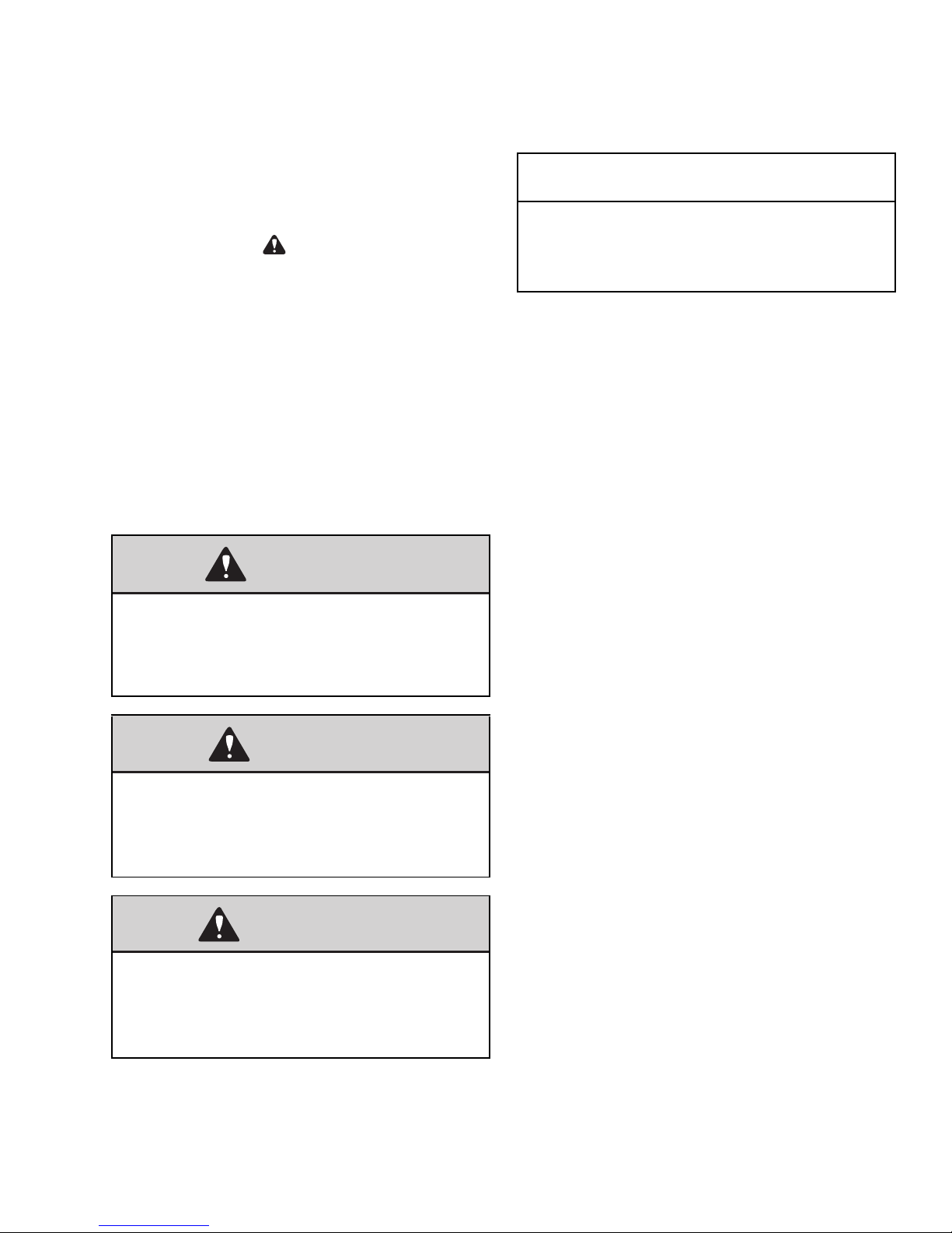
ISO-Style Safety Decal Locations (Serial Numbers AJ02993 and Up) . . . . . . . . . . . . . . . . . . 2-11
ISO-Style Information Decal Locations (Serial Numbers AJ02993 and Up). . . . . . . . . . . . . . 2-14
ANSI-Style Safety Decal Locations (Serial Numbers AH02282 and Before) . . . . . . . . . . . . . 2-16
Chapter 3 - Operation . . . . . . . . . . . . . . . . . . . . . . . . . . . . . . . . . . . . . . . . . . . . . . . . . . . . . . . . . . . . . 3-1
Operating Controls . . . . . . . . . . . . . . . . . . . . . . . . . . . . . . . . . . . . . . . . . . . . . . . . . . . . . . . . . . . . . 3-1
Machine Orientation . . . . . . . . . . . . . . . . . . . . . . . . . . . . . . . . . . . . . . . . . . . . . . . . . . . . . . . . . . 3-1
Ignition Key Switch . . . . . . . . . . . . . . . . . . . . . . . . . . . . . . . . . . . . . . . . . . . . . . . . . . . . . . . . . 3-13
Battery Disconnect Switch . . . . . . . . . . . . . . . . . . . . . . . . . . . . . . . . . . . . . . . . . . . . . . . . . . . . 3-13
Travel Controls . . . . . . . . . . . . . . . . . . . . . . . . . . . . . . . . . . . . . . . . . . . . . . . . . . . . . . . . . . . . 3-14
Tilting the Cab or Canopy . . . . . . . . . . . . . . . . . . . . . . . . . . . . . . . . . . . . . . . . . . . . . . . . . . . . 3-15
SAE Operating Controls . . . . . . . . . . . . . . . . . . . . . . . . . . . . . . . . . . . . . . . . . . . . . . . . . . . . . . 3-17
ISO Operating Controls . . . . . . . . . . . . . . . . . . . . . . . . . . . . . . . . . . . . . . . . . . . . . . . . . . . . . . 3-17
Boom Swivel/Auxiliary Hydraulics Pedal . . . . . . . . . . . . . . . . . . . . . . . . . . . . . . . . . . . . . . . . 3-18
Dozer Blade . . . . . . . . . . . . . . . . . . . . . . . . . . . . . . . . . . . . . . . . . . . . . . . . . . . . . . . . . . . . . . . 3-18
Throttle Lever . . . . . . . . . . . . . . . . . . . . . . . . . . . . . . . . . . . . . . . . . . . . . . . . . . . . . . . . . . . . . . 3-19
Optional Auto-Idle Feature. . . . . . . . . . . . . . . . . . . . . . . . . . . . . . . . . . . . . . . . . . . . . . . . . . . . 3-19
Operator’s Seat Adjustments . . . . . . . . . . . . . . . . . . . . . . . . . . . . . . . . . . . . . . . . . . . . . . . . . . 3-20
Arm rests. . . . . . . . . . . . . . . . . . . . . . . . . . . . . . . . . . . . . . . . . . . . . . . . . . . . . . . . . . . . . . . . . . 3-20
Seat Belt . . . . . . . . . . . . . . . . . . . . . . . . . . . . . . . . . . . . . . . . . . . . . . . . . . . . . . . . . . . . . . . . . . 3-21
Ventilation . . . . . . . . . . . . . . . . . . . . . . . . . . . . . . . . . . . . . . . . . . . . . . . . . . . . . . . . . . . . . . . . 3-21
Mounting/Removing Buckets . . . . . . . . . . . . . . . . . . . . . . . . . . . . . . . . . . . . . . . . . . . . . . . . . . 3-25
Auxiliary Hydraulics Connections . . . . . . . . . . . . . . . . . . . . . . . . . . . . . . . . . . . . . . . . . . . . . . 3-27
Machine Operation . . . . . . . . . . . . . . . . . . . . . . . . . . . . . . . . . . . . . . . . . . . . . . . . . . . . . . . . . . . . 3-28
Pre-Operation Checklist . . . . . . . . . . . . . . . . . . . . . . . . . . . . . . . . . . . . . . . . . . . . . . . . . . . . . . 3-28
Engine Shut Down . . . . . . . . . . . . . . . . . . . . . . . . . . . . . . . . . . . . . . . . . . . . . . . . . . . . . . . . . . 3-30
Travel . . . . . . . . . . . . . . . . . . . . . . . . . . . . . . . . . . . . . . . . . . . . . . . . . . . . . . . . . . . . . . . . . . . . 3-30
Machine Operation . . . . . . . . . . . . . . . . . . . . . . . . . . . . . . . . . . . . . . . . . . . . . . . . . . . . . . . . . . 3-32
Operating on Slopes . . . . . . . . . . . . . . . . . . . . . . . . . . . . . . . . . . . . . . . . . . . . . . . . . . . . . . . . . 3-33
Cold Weather Operation . . . . . . . . . . . . . . . . . . . . . . . . . . . . . . . . . . . . . . . . . . . . . . . . . . . . . . 3-34
Operating in Water . . . . . . . . . . . . . . . . . . . . . . . . . . . . . . . . . . . . . . . . . . . . . . . . . . . . . . . . . . 3-34
Swiveling the Boom . . . . . . . . . . . . . . . . . . . . . . . . . . . . . . . . . . . . . . . . . . . . . . . . . . . . . . . . . 3-34
Grading . . . . . . . . . . . . . . . . . . . . . . . . . . . . . . . . . . . . . . . . . . . . . . . . . . . . . . . . . . . . . . . . . . . 3-35
Excavation . . . . . . . . . . . . . . . . . . . . . . . . . . . . . . . . . . . . . . . . . . . . . . . . . . . . . . . . . . . . . . . . 3-36
Excavating . . . . . . . . . . . . . . . . . . . . . . . . . . . . . . . . . . . . . . . . . . . . . . . . . . . . . . . . . . . . . . . . 3-37
Loading Vehicles . . . . . . . . . . . . . . . . . . . . . . . . . . . . . . . . . . . . . . . . . . . . . . . . . . . . . . . . . . . 3-38
Transporting . . . . . . . . . . . . . . . . . . . . . . . . . . . . . . . . . . . . . . . . . . . . . . . . . . . . . . . . . . . . . . . 3-39
Optional Controls . . . . . . . . . . . . . . . . . . . . . . . . . . . . . . . . . . . . . . . . . . . . . . . . . . . . . . . . . . . . . . 3-41
Proportional Auxiliary Hydraulic
Joystick Control (Option) . . . . . . . . . . . . . . . . . . . . . . . . . . . . . . . . . . . . . . . . . . . . . . . . . . . . . 3-41
Two-Speed Variable Auxiliary Hydraulic Mode Selection . . . . . . . . . . . . . . . . . . . . . . . . . . . 3-42
Printed in U.S.A. ii 918070/FP0811
Page 5

Auxiliary Hydraulic Hammer Operation . . . . . . . . . . . . . . . . . . . . . . . . . . . . . . . . . . . . . . . . . 3-43
Chapter 4 - Maintenance . . . . . . . . . . . . . . . . . . . . . . . . . . . . . . . . . . . . . . . . . . . . . . . . . . . . . . . . . . . 4-1
General Information . . . . . . . . . . . . . . . . . . . . . . . . . . . . . . . . . . . . . . . . . . . . . . . . . . . . . . . . . . . . 4-1
Care and Servicing . . . . . . . . . . . . . . . . . . . . . . . . . . . . . . . . . . . . . . . . . . . . . . . . . . . . . . . . . . . 4-1
Maintenance Safety. . . . . . . . . . . . . . . . . . . . . . . . . . . . . . . . . . . . . . . . . . . . . . . . . . . . . . . . . . . 4-2
Maintenance Label Symbols. . . . . . . . . . . . . . . . . . . . . . . . . . . . . . . . . . . . . . . . . . . . . . . . . . . . 4-3
Maintenance Label . . . . . . . . . . . . . . . . . . . . . . . . . . . . . . . . . . . . . . . . . . . . . . . . . . . . . . . . . . . 4-4
Maintenance Schedule . . . . . . . . . . . . . . . . . . . . . . . . . . . . . . . . . . . . . . . . . . . . . . . . . . . . . . . . . . . 4-5
Check, Clean and Inspect . . . . . . . . . . . . . . . . . . . . . . . . . . . . . . . . . . . . . . . . . . . . . . . . . . . . . . 4-5
Fluid and Filter Changes. . . . . . . . . . . . . . . . . . . . . . . . . . . . . . . . . . . . . . . . . . . . . . . . . . . . . . . 4-6
Cab Air Conditioning . . . . . . . . . . . . . . . . . . . . . . . . . . . . . . . . . . . . . . . . . . . . . . . . . . . . . . . . . 4-7
Cab Functional Checks . . . . . . . . . . . . . . . . . . . . . . . . . . . . . . . . . . . . . . . . . . . . . . . . . . . . . . . . 4-7
Leakage Checks . . . . . . . . . . . . . . . . . . . . . . . . . . . . . . . . . . . . . . . . . . . . . . . . . . . . . . . . . . . . . 4-7
Lubrication . . . . . . . . . . . . . . . . . . . . . . . . . . . . . . . . . . . . . . . . . . . . . . . . . . . . . . . . . . . . . . . . . 4-8
Recommended Lubricants . . . . . . . . . . . . . . . . . . . . . . . . . . . . . . . . . . . . . . . . . . . . . . . . . . . . . 4-9
Engine . . . . . . . . . . . . . . . . . . . . . . . . . . . . . . . . . . . . . . . . . . . . . . . . . . . . . . . . . . . . . . . . . . . . . 4-9
Changing Engine Oil and Filter . . . . . . . . . . . . . . . . . . . . . . . . . . . . . . . . . . . . . . . . . . . . . . . . 4-10
Air Cleaner Service. . . . . . . . . . . . . . . . . . . . . . . . . . . . . . . . . . . . . . . . . . . . . . . . . . . . . . . . . . 4-10
Fuel System. . . . . . . . . . . . . . . . . . . . . . . . . . . . . . . . . . . . . . . . . . . . . . . . . . . . . . . . . . . . . . . . 4-11
Cooling System. . . . . . . . . . . . . . . . . . . . . . . . . . . . . . . . . . . . . . . . . . . . . . . . . . . . . . . . . . . . . 4-14
Electrical System . . . . . . . . . . . . . . . . . . . . . . . . . . . . . . . . . . . . . . . . . . . . . . . . . . . . . . . . . . . 4-14
Battery. . . . . . . . . . . . . . . . . . . . . . . . . . . . . . . . . . . . . . . . . . . . . . . . . . . . . . . . . . . . . . . . . . . . 4-15
Hydraulic System . . . . . . . . . . . . . . . . . . . . . . . . . . . . . . . . . . . . . . . . . . . . . . . . . . . . . . . . . . . 4-17
Checking and Adjusting V-Belt Tension . . . . . . . . . . . . . . . . . . . . . . . . . . . . . . . . . . . . . . . . . 4-22
Checking and Adjusting Air Conditioning V-Belt Tension . . . . . . . . . . . . . . . . . . . . . . . . . . . 4-22
Track System . . . . . . . . . . . . . . . . . . . . . . . . . . . . . . . . . . . . . . . . . . . . . . . . . . . . . . . . . . . . . . 4-23
Windshield Washer Fluid . . . . . . . . . . . . . . . . . . . . . . . . . . . . . . . . . . . . . . . . . . . . . . . . . . . . . 4-26
Long-Term Storage . . . . . . . . . . . . . . . . . . . . . . . . . . . . . . . . . . . . . . . . . . . . . . . . . . . . . . . . . . . . 4-26
Before Storage . . . . . . . . . . . . . . . . . . . . . . . . . . . . . . . . . . . . . . . . . . . . . . . . . . . . . . . . . . . . . 4-26
After Storage. . . . . . . . . . . . . . . . . . . . . . . . . . . . . . . . . . . . . . . . . . . . . . . . . . . . . . . . . . . . . . . 4-27
Chapter 5 - Troubleshooting . . . . . . . . . . . . . . . . . . . . . . . . . . . . . . . . . . . . . . . . . . . . . . . . . . . . . . . . 5-1
Engine . . . . . . . . . . . . . . . . . . . . . . . . . . . . . . . . . . . . . . . . . . . . . . . . . . . . . . . . . . . . . . . . . . . . . . . 5-1
Indicator Lamps . . . . . . . . . . . . . . . . . . . . . . . . . . . . . . . . . . . . . . . . . . . . . . . . . . . . . . . . . . . . . . . . 5-3
Seals and Hoses . . . . . . . . . . . . . . . . . . . . . . . . . . . . . . . . . . . . . . . . . . . . . . . . . . . . . . . . . . . . . . . . 5-3
Traveling Gear . . . . . . . . . . . . . . . . . . . . . . . . . . . . . . . . . . . . . . . . . . . . . . . . . . . . . . . . . . . . . . . . . 5-4
Bucket, Boom and Dozer Blade . . . . . . . . . . . . . . . . . . . . . . . . . . . . . . . . . . . . . . . . . . . . . . . . . . . 5-4
Engine Error Codes . . . . . . . . . . . . . . . . . . . . . . . . . . . . . . . . . . . . . . . . . . . . . . . . . . . . . . . . . . . . . 5-5
Error Diagnostic Code Examples . . . . . . . . . . . . . . . . . . . . . . . . . . . . . . . . . . . . . . . . . . . . . . . . 5-5
Engine Diagnostic Codes Table . . . . . . . . . . . . . . . . . . . . . . . . . . . . . . . . . . . . . . . . . . . . . . . . . 5-6
Chapter 6 - index. . . . . . . . . . . . . . . . . . . . . . . . . . . . . . . . . . . . . . . . . . . . . . . . . . . . . . . . . . . . . . . . . . 6-1
918070/FP0811 iii Printed in U.S.A.
Page 6

NOTES
Printed in U.S.A. iv 918070/FP0811
Page 7

CHAPTER 1 – GENERAL
1
2
INFORMATION
INTRODUCTION
The information in this Operator’s Manual was written
to give the owner/operator assistance in preparing,
adjusting, maintaining and servicing the Compact
Excavator. More important, this manual provides an
operating plan for safe and proper use of the machine.
Major points of safe operation are detailed in Chapter 2
– Safety.
Read and understand the contents of this manual com-
pletely and become familiar with the machine before
attempting to operate it. Contact your dealer to obtain
additional manuals.
Throughout this manual, information is introduced by
the word Note or IMPORTANT. Be sure to read the
message carefully and comply with the message. Fol-
lowing this information will improve operating and
maintenance efficiency, help to avoid breakdown and
damage and extend the service life of the machine.
Do not use the machine for any application or purpose
other than described in this manual. Consult your
dealer before using special attachments or equipment
not approved for use with the machine. Any person
making unauthorized modifications is responsible for
the consequences.
The Gehl dealer network stands ready to provide any
assistance you may require, including genuine Gehl
service parts. All service parts should be obtained from
your dealer. Give complete information about the part
and include the model and serial number of the
machine. Record the serial number in the following
space, as a handy reference.
Purchased from:______________________________
Date of Purchase: ____________________________
Model No.: _________________________________
Serial No.: __________________________________
Serial Number Location
The machine serial number plate (1, Figure 1-1) is
located on the front frame, below the operator’s cab.
The cab/canopy serial number (2) is located on the right
rear of the frame next to the rear window.
The use of the machine is subject to certain hazards
that cannot be eliminated by mechanical means - only
by exercising intelligence, care, and common sense.
Such hazards include, but are not limited to: hillside
operation, overloading, instability of the load, poor
maintenance and using the equipment for purposes for
which it was not intended or designed.
It is essential to have competent and careful operators,
not physically or mentally impaired, who are thor-
oughly trained in safe operation and proper load han-
dling.
It is recommended that operators be capable of obtain-
ing a valid motor vehicle operator’s license.
Some illustrations in this manual may show doors,
guards and shields open or removed for illustrative pur-
poses only. BE SURE all doors, guards and shields are
in their proper operating positions BEFORE starting
the engine to operate the machine.
Manitou Americas, Inc. reserves the right to make
changes and improvements in the design and construc-
tion of any part without incurring the obligation to
install such changes on any unit previously delivered.
Figure 1-1 Serial Number Plate Locations
918070/FP0811 1-1 Printed in U.S.A.
Page 8

Engine Serial Number Location
Engine serial number label
Model 503Z: Serial numbers AH00579 and up
Model 603: Serial numbers AH00645 and up
Engine serial number label
Model 503Z: Serial numbers AH00578 and before
Model 603: Serial numbers AH00644 and before
The engine serial number label is located on the cylinder head cover
Ownership Change
If this machine was purchased “used,” or if the owner’s
address has changed, please provide your GEHL dealer
or GEHL Company Service Department with the
owner’s name and current address, along with the
machine model and serial numbers. This will allow the
registered owner information to be updated, so that the
owner can be notified directly in case of an important
product issue, such as a safety update program.
Printed in U.S.A. 1-2 918070/FP0811
Page 9
Excavator Component Indentification
Dipper Arm Cylinder
Boom
Bucket
Bucket Cylinder
Dipper Arm
Boom Cylinder
Dozer Blade
Track Frame
Travel Drive Motor
Swing Frame/
Superstructure
Hydraulic/Fuel
Tank Cover
Counterweight
Operator ’s Seat
Operati o n C o nt rols
Swing Cylinder
Engine Cover
Figure 1-2 Component Names
918070/FP0811 1-3 Printed in U.S.A.
Page 10

SPECIFICATIONS
Fluid Capacities/Lubricants
Note: Capacities i ndicated are approximate.
Component/Applica-
tion
Diesel Engine
Travelling Drive Gearbox Oil
Hydraulic Oil Tank
Lubricant Specification Season/Temper-
ature
SAE 10W-40 (according to
Engine Oil
b
DIN 51502); API: CD, CF,
CF-4, CI-4
-4°F (-20°C)
+104°F (+40°C)
SAE E3, E4, E5
Q8 T 55, SAE80W-90
Gearbox Oil
c
FINA PONTONIC GLS
Year-round
SAE80W-90
HVLP46 (according to DIN
Hydraulic Oil
Biodegradable Oil
d
51524 section 3)
PANOLIN HLP Synth 46
e
FINA BIOHYDRAN SE 46
Year-round 11.9 gal. (45 L)
Capacity
Model 503Z: 8.2
qts. (7.8 L)
Model 603: 10.8
qts. (10.2 L)
About 0.3 gal.
(1.3 L) each
a
BP BIOHYD SE-46
Grease
Grease Fittings
Battery Terminals
Roller and Friction
Bearings
Open Gear (live
ring gears)
Multipurpose
Grease
f
Acid-proof Grease
FINA Energrease L21M
Year-round As Required
BP Energrease MP-MG2
FINA Energrease L21M Year-round As Required
g
FINA Marson L2 Year-round As Required
No. 2-D, DIN 51601 grade Over 39°F (4°C)
Diesel FuelTank Diesel Fuel
Engine and Hydraulic
Oil Cooler
Coolant Water + antifreeze; SP-C Year-round 1.8 gal. (5.5 L)
Refrigerating Agent R134a
Air Conditioning
Compressor Oil Sanden SP10
No. 1-D, DIN 51601 grade
Below 39°F
(4°C)
Year-round
20.6 gal. (78 L)
1.7 lbs. (750 g)
3
7.1 in
(116.5 cm3)
Windshield Washer Cleaning Agent Water + Antifreeze Year-round 5.3 gal. (2 L)
a. Capacities shown are approximate; use only oil level check to determine correct oil level
b. BP Vanellus MG 15W40, BP Vanellus C-Extra 10W30, Chevron Delo 400 15W40 or equivalent; Refer to engine operator’s manual for more
detailed information about recommended oil grade type use depending upon ambient temperature.
c. Hypoid gearbox oil based on basic mineral oil (API GL-4, GL-5)
d. Mobile DTE15M, Amoco Rykon 46, BP Energol HLP-HD 46 or equivalent
e. Hydraulic ester oils (HEES)
f. FINA Energrease 21M, Chevron RPM Heavy-Duty Grease No. 2, Mobilgrease Moly 52, or BP Energrease Moly EP2
g. Standard acid-proof grease
Printed in U.S.A. 1-4 918070/FP0811
Page 11

Engine
Engine 503Z 603
Engine Model Serial Numbers AH00579 and up:
Yanmar 4TNV88-BPNS
EPA Tier III
S/N AC02471-AH00578:
Yanmar 4TNV88-PNS
EPA Tier II
Type Water-cooled 4-stroke, 4 cylinder diesel engine
Displacement 134 cu. in. (2.19 L) 202 cu. in. (3.32 L)
Bore and Stroke 3.5 x 3.5 in. (88 x 90 mm) 3.9 x 4.3 in. (98 x 110 mm)
Horsepower (DIN) 37.8 hp (28.2 kW) @ 2400 rpm 57.0 hp (42.5 kW) @ 2100 rpm
Max. Torque 102 lb.-ft. (138 Nm) @ 1100 rpm 184 lb.-ft. (249 Nm) @ 1400 rpm
Max. Engine Speed (with no load) 2575 +/- 50 rpm 2275 +/- 50 rpm
Idle Engine Speed 1050 +/- 50 rpm
Fuel Injection System Direct injection
Starting Aid Glow plug (Preheating time 10-15 seconds)
Max. Inclined Angle (engine still sup-
plied with oil)
Note: The machine’s theoretical climbing ability
25° in all directions
(30°/ 58%) exceeds this angle!
Exhaust Emission Compliance 97/68 EC; U.S. EPA
Engine Oil Capacity 8.2 qts. (7.8 L) 10.7 qts. (10.1 L)
Engine Coolant Capacity 7.4 qts. (7.0 L)
Serial Numbers AH00645 and up:
Yanmar 4TNV98-ZVNS
EPA Tier III
S/N AC02513-AH00644:
Yanmar 4TNV98-VNS
EPA Tier II
Hydraulic System
Hydraulic System 503Z 603
Pump Two variable-displacement + two gear pumps
Flow Rate 2 x 14.2 gpm + 10.9 gpm + 3.0
gpm @ 2590 rpm
(2 x 53.6 L/min + 41.4 L/min
+11.6 L/min) @ 2590 rpm
Operating Pressure (working and driving) 3408 psi (235 bar) 3553 psi (245 bar)
Operating Pressure (swing unit) 3336 psi (230 bar) 3480 psi (240 bar)
Hydraulic Fluid Cooler Standard
Hydraulic Reservoir (system capacity) 21.1 gal. (80 L)
Filter Return filter
2 x 15.7 gpm + 11.8 gpm + 2.5
gpm @ 2290 rpm
(2 x 59.6.1 L/min + 44.7 L/min +
9.6 L/min) @ 2130 rpm
918070/FP0811 1-5 Printed in U.S.A.
Page 12

Undercarriage and Swing System
F3
F4
F8
F9
F10
F5 F6 F7
Serial Numbers to
AH02282
Located on top of right
inside cab/canopy
interior trim.
Serial Numbers
AJ02993 and up
Located on inside of
right cab/canopy
interior trim
Undercarriage and Swing System 503Z 603
Travel Speed
Low Speed 1.7 mph (2.74 km/h) 1.7 mph (2.76 km/h)
High Speed 2.8 mph (4.56 km/h) 3.0 mph (4.76 km/h)
Ground Clearance 11.8” (300 mm) 13.2” (335 mm)
Swing Speed 8.7 rpm 9.0 rpm
Gradability 30
° (58%)
Rubber Track Width 15.7” (400 mm)
Number of Track Rollers 4 per side 5 per side
Average Ground Pressure
3.84 psi (0.28 kg/cm
2
)
Dozer Blade
Dozer Blade 503Z 603
Width 78.3” (1990 mm) 78.3” (1990 mm)
Height 15.0” (380 mm) 16.7” (425 mm)
Maximum Lift Above Ground 15.2” (385 mm) 15.3” (390 mm)
Maximum Depth Below Ground 15.4” (390 mm) 15.7” (400 mm)
Electrical System
Alternator 12-V, 55-A
Starter 12-V, 2.3-kW
Battery 12-V, 88-Ah, BCI group size 49 (93 opt.), 680 CCA
Socket 15-A max. - Cigarette lighter
Fuse Box in Instrument Panel
Fuse
No.
F3 10 Amp Indicators, cut-off solenoid, relays
F4 10 Amp Boom light
F5 15 Amp Roof lights
F6 10 Amp Valves, horn
F7 15 Amp Heating, air conditioning
F8 10 Amp Windshield wiper, interior light
F9 10 Amp Rotating beacon, radio
F10 15 Amp Socket, cigarette lighter
Rated
Current
Protected Circuit
Printed in U.S.A. 1-6 918070/FP0811
Page 13

Main Fuse Box and Relays
K9
K5
F1
F2
K7
K6
K8
V1
Relays
Fuse No. Rated Curren t Protected Circuit
F1 40 Amp Start, preheat, cut-off solenoid
F2 50 Amp Main fuse, ignition lock
Relay No. Protected Circuit
K9 Cut-off solenoid
K5 Preheating
Relay No. Protected Circuit
K6 Preheating timer
K7 Starting relay
K8 Cut-off solenoid
V1 Diode
918070/FP0811 1-7 Printed in U.S.A.
Page 14

Sound Levels
503Z 603
Sound Power 96 dB(A) 98 dB(A)
Sound Pressure 76 dB(A) 74 dB(A)
Coolant Compound Table
Outside temperature
Up to °F (°C)
39 (4) 99
14 (-10) 79 20
-4 (-20) 65 34
-13 (-25) 59 40
-22(-30) 55 44
Water Anticorrosion agent Antifreeze agent
% by vol-
ume
Coolant: Halvoline XLC (based on ethylene glycol)
in³/gal (cm³/L) % by volume % by volume
2.6 (10) 1
–
Printed in U.S.A. 1-8 918070/FP0811
Page 15
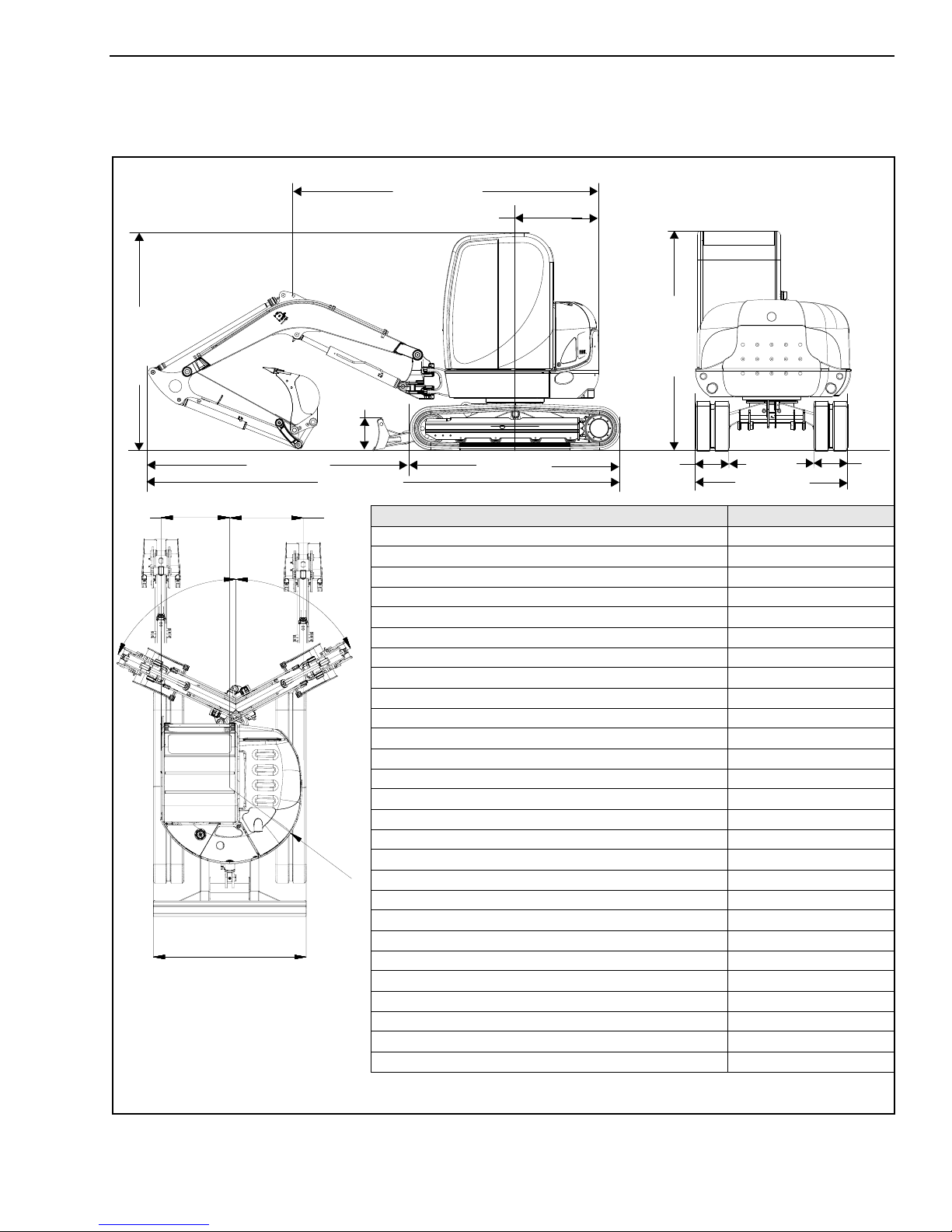
503Z General Specifications
8’2” (2500 mm)
12’ 2” (3097 mm)
8’5” (2570 mm)
6’6” (1990 mm)
1’3”
3’10”
18’4” (5600 mm)
3’3” (995 mm)
11’9” (3583 mm)
8’5” (2570 mm)
1’3” (380 mm)
(400 mm)
(1190 mm)
(400 mm)
1’3”
General Specifications
503Z
Weight 10,582 lbs. (4800 kg)
Height 8’5” (2570 mm)
Width 6’6” (1990 mm)
Transport length 18’4” (5600 mm)
Dipper arm length (Standard Arm) 4’9” (1450) mm
Dipper arm length (Optional Long Arm) 5’9” (1750 mm)
Max. digging depth w/ Standard Arm 11’9” (3570 mm)
Max. digging depth w/ Optional Long Arm 12’8” (3870 mm)
Max. vertical digging depth w/ Standard Arm 8’8” (2630 mm)
Max. vertical digging depth w/ Optional Long Arm 9’7” (2915 mm)
Max. digging height w/ Standard Arm 17’5” (5320 mm)
Max. digging height w/ Optional Long Arm 18’1” (5500 mm)
Max. dump height w/ Standard Arm 12’2” (3720 mm)
Max. dump height w/ Optional Long Arm 12’10” (3900 mm)
Max. digging radius w/ Standard Arm 19’9” (6030 mm)
Max. digging radius w/ Optional Long Arm 20’8” (6300 mm)
Max. reach at ground level w/ Standard Arm 19’4” (5900 mm)
Max. reach at ground level w/ Optional Long Arm 20’3” (6185 mm)
Max. breakout force at bucket tooth 7,599 lbf (33.8 kN)
Max. tearout force (Standard Arm) 5,980 lbf (26.6 kN)
Max. tearout force (Optional Long Arm) 5,283 lbf (23.5 kN)
Min. tail end slewing radius 3’3” (995 mm)
Max. tail end lateral projection over tracks 0’0” (0 mm)
Max. boom distance to bucket center (right side) 3’1” (960 mm)
Max. boom distance to bucket center (left side) 2’11” (895 mm)
Max. boom slew angle (left side) 65°
Max. boom slew angle (right side) 61°
3’1”
6
1°
6
5
°
R
3
’
3
”
(
9
9
5
m
m
)
6’6” (1990 mm)
(956 mm)
2’11”
(893 mm)
918070/FP0811 1-9 Printed in U.S.A.
Page 16
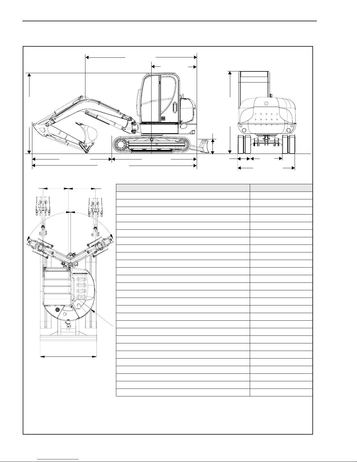
603 General Specifications
8’5” (2570 mm)
19’2” (5800 mm)
8’2” (2500 mm)
10’9” (3280 mm )
13’0” (3967 mm)
4’9” (1465 mm)
1’5” (425 mm)
6’6” (1990 mm)
1’3”
3’10”
(400 mm)
(1190 mm)
8’5” (2570 mm)
1’9”
(535 mm)
°
5
7
6’6” (1990 m m )
2’5”
(745 mm)
5
1
°
R
(
4
1
’
4
9
6
”
5
m
m
)
General Specifications 603
Weight 12,566 lbs. (5700 kg)
Height 8’5” (2570 mm)
Width 6’6” (1990 mm)
Transport length 19’0” (5800 mm)
Dipper arm length (Standard Arm) 5’6” (1685 mm)
Dipper arm length (Optional Long Arm) 6’6” (1985 mm)
Max. digging depth w/ Standard Arm 12’7” (3845 mm)
Max. digging depth w/ Optional Long Arm 13’7” (4140 mm)
Max. vertical digging depth w/ Standard Arm 9’4” (2855 mm)
Max. vertical digging depth w/ Optional Long Arm 10’3” (3135 mm)
Max. digging height w/ Standard Arm 18’6” (5660 mm)
Max. digging height w/ Optional Long Arm 19’2” (5850 mm)
Max. dump height w/ Standard Arm 13’1” (3995 mm)
Max. dump height w/ Optional Long Arm 13’8” (4185 mm)
Max. digging radius w/ Standard Arm 20’ 4” (6210 mm)
Max. digging radius w/ Optional Long Arm 21’3” (6490 mm)
Max. reach at ground level w/ Standard Arm 19’11” (6090 mm)
Max. reach at ground level w/ Optional Long Arm 20’11” (6380 mm)
Max. breakout force at bucket tooth 8,925 lbf (39.7 kN)
Max. tearout force (Standard Arm) 6,317 lbf (28.1 kN)
Max. tearout force (Optional Long Arm) 5,642 lbf (25.1 kN)
Min. tail end slewing radius 4’9” (1465 mm)
Max. tail end lateral projection over tracks 1’6” (470 mm)
Max. boom distance to bucket center (right side) 2’5” (745 mm)
Max. boom distance to bucket center (left side) 1’9” (535 mm)
Max. boom slew angle (left side) 75°
Max. boom slew angle (right side) 51°
Printed in U.S.A. 1-10 918070/FP0811
Page 17

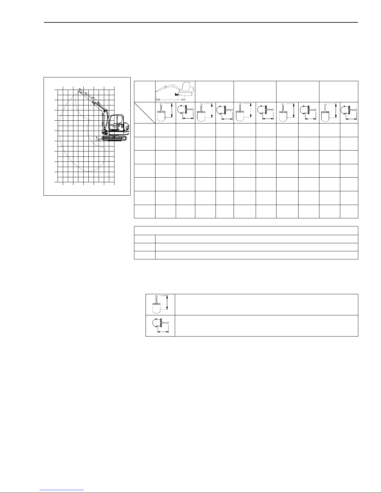
Fields of Applications
Attachment Size Capacity
Heavy-Duty Bucket 10 in. (250 mm)
16 in. (400 mm)
20 in. (500 mm)
24 in. (600 mm)
30 in. (700 mm)
36 in. (900 mm)
Ditching Bucket 48 in. (1000 mm)
Ditch Bucket (503Z only) 48 in. (1000 mm)
55 in. (1400 mm)
Swivel Bucket 48 in. (1200 mm)
55 in. (1400 mm)
2.5 ft
3.3 ft
3.7 ft
6.4 ft
8.8 ft
9.8 ft
5.9 ft
7.0 ft
8.4 ft
5.9 ft
7.0 ft
5.9 ft
3
3
3
3
3
3
3
3
3
3
3
3
(0.070 M3)
(0.093 M3)
(0.104 M3)
(0.181 M3)
(0.249 M3)
(0.278 M3)
(0.167 M3)
(0.196 M3)
(0.238 M3)
(0.167 M3)
(0.198 M3)
(0.167 M3)
918070/FP0811 1-11 Printed in U.S.A.
Page 18

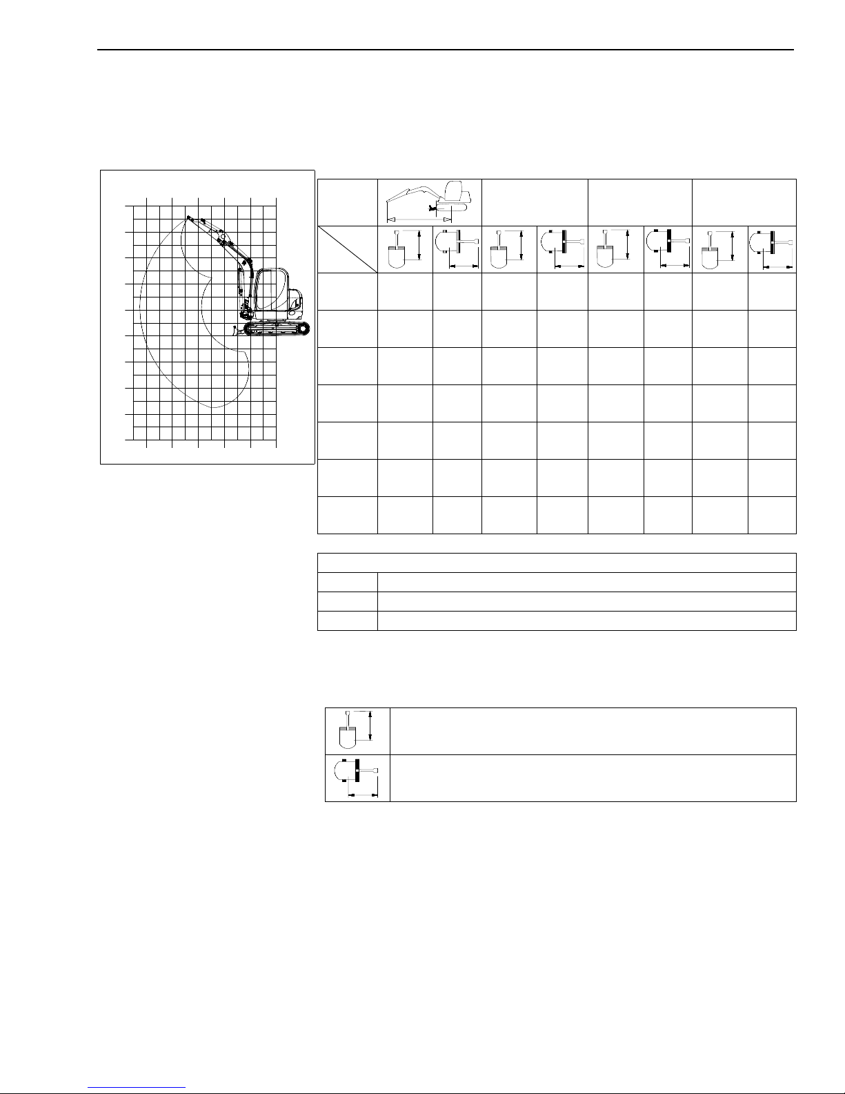
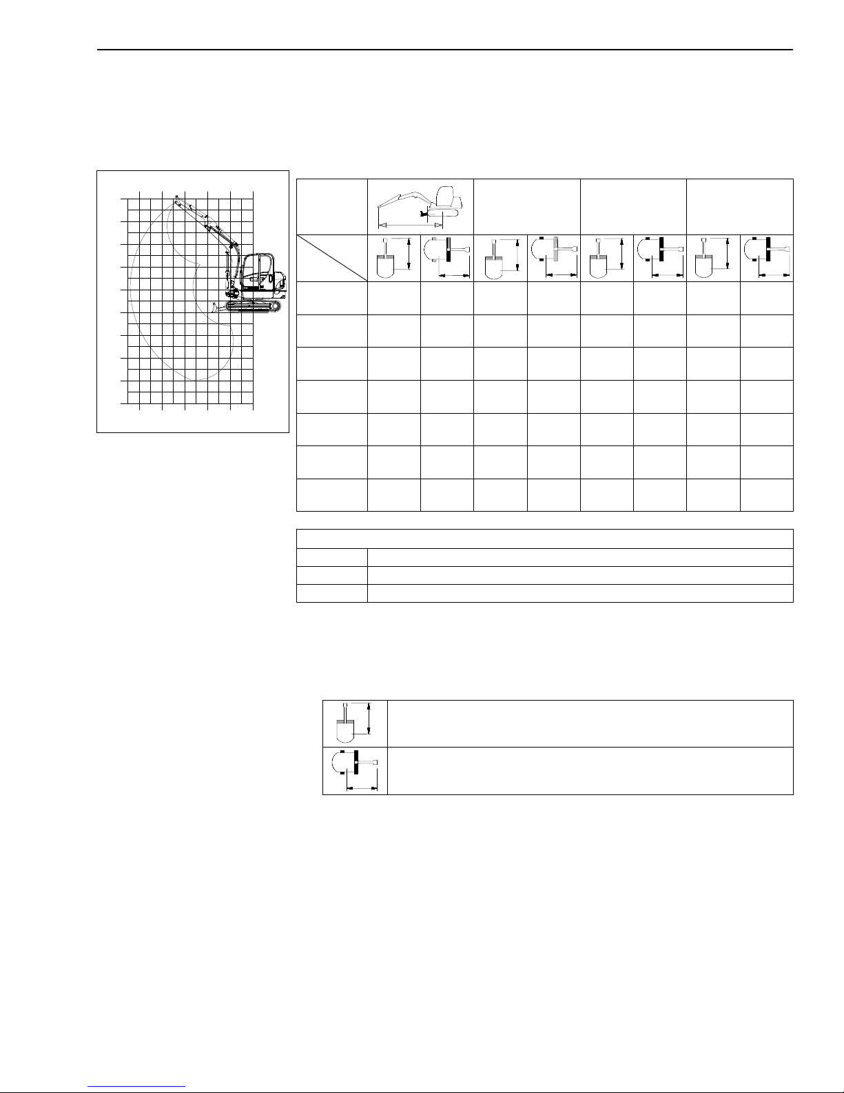
Load Diagrams
0'0"
(0.0 m)
3'3"
(1.0 m)
6'6"
(2.0 m)
9'9"
(3.0 m)
13'0"
(4.0 m)
16'3"
(5.0 m)
0'0"
(0.0 m)
3'3"
(1.0 m)
6'6"
(2.0 m)
9'9"
(3.0 m)
13'0"
(4.0 m)
16'3"
(5.0 m)
3'3"
(1.0 m)
6'6"
(2.0 m)
9'9"
(3.0 m)
13'0"
(4.0 m)
-13'0"
(-4.0 m)
16'3"
(5.0 m)
-3'3"
(-1.0 m)
-6'6"
(-2.0 m)
-9'9"
(-3.0 m)
0'0"
(0.0 m)
503Z Load Diagram - Standard Dipper Arm Maximum Permissible Loads
13’0”
A
B
13’0”
(4.0 m)
9’9”
(3.0 m)
6’6”
(2.0 m)
3’3”
(1.0 m)
0’0”
(0.0 m)
-3’3”
(-1.0 m)
-6’6”
(-2.0 m)
2,337*
(1060*)
2,260*
(1025*)
2,304*
(1045*)
2,403*
(1090*)
2,524*
(1145*)
2,668*
(1210*)
2,767*
(1255*)
1,786
(810)
1,290
(585)
1,080
(490)
1,003
(455)
1,014
(460)
1,135
(515)
1,554
(705)
(4.0 m)
2,227*
(1010*)
2,612*
(1185*)
3,120*
(1415*)
3,428*
(1555*)
3,329*
(1510*)
1,720
(780)
1,609
(730)
1,477
(670)
1,378
(625)
1,345
(610)
(3.0 m)
3,483*
(1580*)
4,905
(2225*)
5,368*
(2435*)
5,049*
(2290*)
3,924*
(1780*)
Maximum permissible load on standard dipper arm
A Overhang from the center of the turntable
B Height of load fixing point
* Lifting capacity hydraulically limited
9’9”
2,535
(1150)
2,183
(990)
2,028
(920)
2,017
(915)
2,094
(950)
(2.0 m)
8,973*
(4070*)
6,614*
(3000*)
6’6”
3,946
(1790)
4,101
(1860)
All table values are in lbs. (kg) and for a machine in a horizontal position on
firm ground without bucket.
If equipped with a bucket or other implements, lift capacity or tilt load is
reduced by bucket or implement weight.
Calculation basis: According to ISO 10567.
The excavator's lift capacity is restricted by the settings of the pressure relief
valves and the hydraulic system's stabilizing features.
Neither 75% of the static tilt load nor 87% of the hydraulic lift capacity is
exceeded.
Printed in U.S.A. 1-12 918070/FP0811
Dozer blade support in drive direction
Dozer blade support 90° to drive direction
Page 19
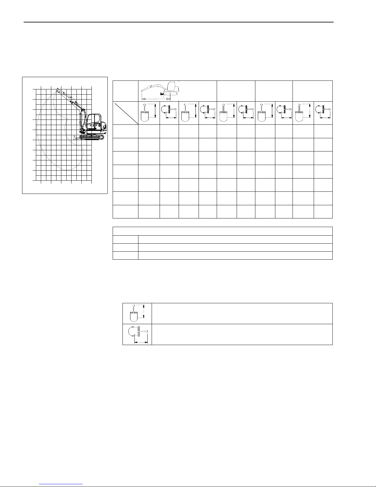
503Z Load Diagram - Extended Dipper Arm (Option)
0'0"
(0.0 m)
3'3"
(1.0 m)
6'6"
(2.0 m)
9'9"
(3.0 m)
13'0"
(4.0 m)
16'3"
(5.0 m)
0'0"
(0.0 m)
3'3"
(1.0 m)
6'6"
(2.0 m)
9'9"
(3.0 m)
13'0"
(4.0 m)
16'3"
(5.0 m)
3'3"
(1.0 m)
6'6"
(2.0 m)
9'9"
(3.0 m)
13'0"
(4.0 m)
-13'0"
(-4.0 m)
16'3"
(5.0 m)
-3'3"
(-1.0 m)
-6'6"
(-2.0 m)
-9'9"
(-3.0 m)
0'0"
(0.0 m)
Maximum permissible loads
13’0”
A
B
13’0”
(4.0 m)
9’9”
(3.0 m)
6’6”
(2.0 m)
3’3”
(1.0 m)
0’0”
(0.0 m)
-3’3”
(-1.0 m)
-6’6”
(-2.0 m)
2,028*
(920*)
2,017*
(915*)
2,061*
(935*)
2,138*
(970*)
2,238*
(1015*)
2,348*
(1065*)
2,447*
(1110*)
1,455
(660)
1,102
(500)
937
(425)
871
(395)
882
(400)
970
(440)
1246
(565)
(4.0 m)
1,951*
(855*)
1,907*
(865*)
2,315*
(1050*)
2,888*
(1310)
3,296*
(1495*)
3,340*
(1515*)
2,756*
(1250*)
1,731
(785)
1,720
(780)
1,609
(730)
1,466
(665)
1,345
(610)
1,301
(590)
1,323
(600)
(3.0 m)
2,899*
(1315*)
4,464*
(2025*)
5,258*
(2385*)
5,181*
(2350*)
4,343*
(1970*)
Maximum permissible load on extended dipper arm
A Overhang from the center of the turntable
B Height of load fixing point
* Lifting capacity hydraulically limited
9’9”
2,579
(1170)
2,227
(1010)
2,017
(915)
1,962
(890)
2,006
(910)
6’6”
(2.0 m)
10,075*
(4570*)
7,915*
(3590*)
3,858
(1750)
3,979
(1805)
918070/FP0811 1-13 Printed in U.S.A.
All table values are in lbs. (kg) and for a machine in a horizontal position on
firm ground without bucket.
Dozer blade support in drive direction
Dozer blade support 90° to drive direction
If equipped with a bucket or other implements, lift capacity or tilt load is
reduced by bucket or implement weight.
Calculation basis: According to ISO 10567.
The excavator's lift capacity is restricted by the settings of the pressure relief
valves and the hydraulic system's stabilizing features.
Neither 75% of the static tilt load nor 87% of the hydraulic lift capacity is
exceeded.
Page 20

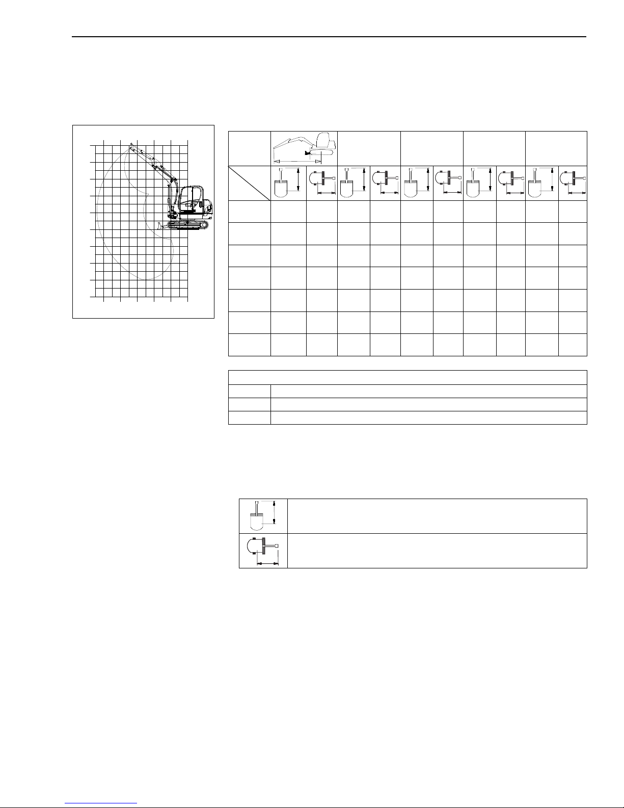
503Z Load Diagram - Standard Dipper Arm with Counterweight
0'0"
(0.0 m)
3'3"
(1.0 m)
6'6"
(2.0 m)
9'9"
(3.0 m)
13'0"
(4.0 m)
16'3"
(5.0 m)
0'0"
(0.0 m)
3'3"
(1.0 m)
6'6"
(2.0 m)
9'9"
(3.0 m)
13'0"
(4.0 m)
16'3"
(5.0 m)
3'3"
(1.0 m)
6'6"
(2.0 m)
9'9"
(3.0 m)
13'0"
(4.0 m)
-13'0"
(-4.0 m)
16'3"
(5.0 m)
-3'3"
(-1.0 m)
-6'6"
(-2.0 m)
-9'9"
(-3.0 m)
0'0"
(0.0 m)
Maximum permissible loads
13’0”
(4.0 m)
A
B
13’3”
(4.0 m)
9’9”
(3.0 m)
6’6”
(2.0 m)
3’3”
(1.0 m)
0’0”
(0.0 m)
-3’3”
(-1.0 m)
-6’6”
(-2.0 m)
2337*
(1060*)
2260*
(1025*)
2304*
(1045*)
2403*
(1090*)
2524*
(1145*)
2668*
(1210*)
2767*
(1255*)
2017
(915)
1488
(675)
1279
(580)
1202
(545)
1213
(550)
1367
(620)
1830
(830)
2227*
(1010*)
2612*
(1185*)
3120*
(1415*)
3428*
(1555*)
3329*
(1510*)
2006
(910)
1907
(865)
1775
(805)
1676
(760)
1642
(745)
3483*
(1580*)
4905*
(2225*)
5368*
(2435*)
5049*
(2290*)
3924*
(1780*)
Maximum permissible load on standard dipper arm
A Reach from live ring center
B Load hook height
* Lift capacity limited by hydraulics
9’9”
(3.0 m)
(1345)
(1185)
(1115)
(1110)
(1140)
2965
2612
2458
2447
2513
(2.0 m)
8973*
(4070*)
6614*
(3000*)
6’6”
4751
(2155)
4905
(2225)
All table values are in lbs. (kg) and for a machine in a horizontal position on
firm ground without bucket.
If equipped with a bucket or other implements, lift capacity or tilt load is
Printed in U.S.A. 1-14 918070/FP0811
reduced by bucket or implement weight.
Calculation basis: According to ISO 10567.
The excavator's lift capacity is restricted by the settings of the pressure relief
valves and the hydraulic system's stabilizing features.
Neither 75% of the static tilt load nor 87% of the hydraulic lift capacity is
exceeded.
Dozer blade support in drive direction
Dozer blade support 90° to drive direction
Page 21
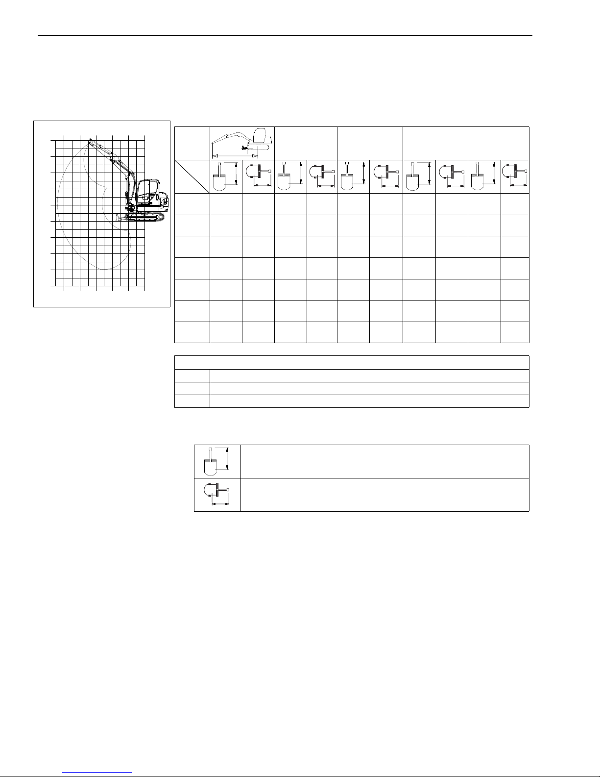
503Z Load Diagram - Extended Dipper Arm with Counterweight
0'0"
(0.0 m)
3'3"
(1.0 m)
6'6"
(2.0 m)
9'9"
(3.0 m)
13'0"
(4.0 m)
16'3"
(5.0 m)
0'0"
(0.0 m)
3'3"
(1.0 m)
6'6"
(2.0 m)
9'9"
(3.0 m)
13'0"
(4.0 m)
16'3"
(5.0 m)
3'3"
(1.0 m)
6'6"
(2.0 m)
9'9"
(3.0 m)
13'0"
(4.0 m)
-13'0"
(-4.0 m)
16'3"
(5.0 m)
-3'3"
(-1.0 m)
-6'6"
(-2.0 m)
-9'9"
(-3.0 m)
0'0"
(0.0 m)
Maximum permissible loads
13’0”
(4.0 m)
A
B
13’3”
(4.0 m)
9’9”
(3.0 m)
6’6”
(2.0 m)
3’3”
(1.0 m)
0’0”
(0.0 m)
-3’3”
(-1.0 m)
-6’6”
(-2.0 m)
2028*
(920*)
2017*
(915*)
2061*
(935*)
2138*
(970*)
2238*
(1015*)
2348*
(1065*)
2447*
(1110*)
1720
(780)
1323
(600)
1146
(520)
1069
(485)
1080
(490)
1190
(540)
1521
(690)
1885*
(855*)
1907*
(865*)
2315*
(1050*)
2888*
(1310*)
3296*
(1495*)
3340*
(1515*)
2756*
(1250*)
1885*
(855*)
1907*
(865*)
1907*
(865*)
1764
(800)
1642
(745)
1587
(720)
1620
(735)
2899*
(1315*)
4464*
(2025*)
5258*
(2385*)
5181*
(2350*)
4343*
(1970*)
Maximum permissible load on extended dipper arm
A Reach from live ring center
B Load hook height
* Lift capacity limited by hydraulics
9’9”
(3.0 m)
(1315*)
2899*
2657
(1205)
2447
(1110)
2392
(1085)
2436
(1105)
(2.0 m)
10,075*
(4570*)
7915*
(3590*)
6’6”
4663
(2115)
4663
(2115)
918070/FP0811 1-15 Printed in U.S.A.
All table values are in lbs. (kg) and for a machine in a horizontal position on
firm ground without bucket.
Dozer blade support in drive direction
Dozer blade support 90° to drive direction
If equipped with a bucket or other implements, lift capacity or tilt load is
reduced by bucket or implement weight.
Calculation basis: According to ISO 10567.
The excavator's lift capacity is restricted by the settings of the pressure relief
valves and the hydraulic system's stabilizing features.
Neither 75% of the static tilt load nor 87% of the hydraulic lift capacity is
exceeded.
Page 22
603 Load Diagram - Standard Dipper Arm
0'0"
(0.0 m)
3'3"
(1.0 m)
6'6"
(2.0 m)
9'9"
(3.0 m)
13'0"
(4.0 m)
16'3"
(5.0 m)
0'0"
(0.0 m)
3'3"
(1.0 m)
6'6"
(2.0 m)
9'9"
(3.0 m)
13'0"
(4.0 m)
16'3"
(5.0 m)
3'3"
(1.0 m)
6'6"
(2.0 m)
9'9"
(3.0 m)
13'0"
(4.0 m)
-13'0"
(-4.0 m)
16'3"
(5.0 m)
-3'3"
(-1.0 m)
-6'6"
(-2.0 m)
-9'9"
(-3.0 m)
0'0"
(0.0 m)
Maximum permissible loads (standard arm)
16’0”
(5.0 m)
13’0”
(4.0 m)
A
B
13’0”
(4.0 m)
9’9”
(3.0 m)
6’6”
(2.0 m)
3’3”
(1.0 m)
0’0”
(0.0 m)
-3’3”
(-1.0 m)
-6’6”
(-2.0 m)
2,888*
(1310*)
2,866*
(1300*)
2,911*
(1320*)
2,998*
(1360*)
3,109*
(1410*)
3,230*
(1465*)
3,296*
(1495*)
2,249
(1020)
1,775
(805)
1,565
(710)
1,488
(675)
1,521
(690)
1,676
(760)
2,127
(965)
2,932*
(1330*)
3,164*
(1435*)
3,296*
(1495*)
1,709
(775)
1,654
(750)
1,609
(730)
2,745*
(1245*)
2,789*
(1265*)
3,285*
(1490*)
3,913*
(1775*)
4,343*
(1970*)
4,332*
(1965*)
2,546
(1155)
2,524
(1145)
2,425
(1100)
2,282
(1035)
2,183
(990)
2,138
(970)
Maximum permissible load on standard dipper arm
A Overhang from the center of the turntable
B Height of load fixing point
* Lifting capacity hydraulically limited
9’9”
(3.0 m)
4,156*
(1885*)
5,765*
(2615*)
6,548*
(2970*)
6,415*
(2910*)
5,401*
(2450*)
3,748
(1700)
3,417
(1550)
3,241
(1470)
3,197
(1450)
3,252
(1475)
6’6”
(2.0 m)
11,045*
(5010*)
8829*
(4005*)
6162
(2795)
6294
(2855)
All table values are in lbs. (kg) and for a machine in a horizontal position on
firm ground without bucket.
If equipped with a bucket or other implements, lift capacity or tilt load is
reduced by bucket or implement weight.
Calculation basis: According to ISO 10567.
The excavator's lift capacity is restricted by the settings of the pressure relief
valves and the hydraulic system's stabilizing features.
Neither 75% of the static tilt load nor 87% of the hydraulic lift capacity is
exceeded.
Printed in U.S.A. 1-16 918070/FP0811
Dozer blade support in drive direction
Dozer blade support 90° to drive direction
Page 23
603 Load Diagram - Extended Dipper Arm (Option)
0'0"
(0.0 m)
3'3"
(1.0 m)
6'6"
(2.0 m)
9'9"
(3.0 m)
13'0"
(4.0 m)
16'3"
(5.0 m)
0'0"
(0.0 m)
3'3"
(1.0 m)
6'6"
(2.0 m)
9'9"
(3.0 m)
13'0"
(4.0 m)
16'3"
(5.0 m)
3'3"
(1.0 m)
6'6"
(2.0 m)
9'9"
(3.0 m)
13'0"
(4.0 m)
-13'0"
(-4.0 m)
16'3"
(5.0 m)
-3'3"
(-1.0 m)
-6'6"
(-2.0 m)
-9'9"
(-3.0 m)
0'0"
(0.0 m)
Maximum permissible loads (extended arm)
16’0”
(5.0 m)
13’0”
(4.0 m)
A
B
13’0”
(4.0 m)
9’9”
(3.0 m)
6’6”
(2.0 m)
3’3”
(1.0 m)
0’0”
(0.0 m)
-3’3”
(-1.0 m)
-6’6”
(-2.0 m)
2,623*
(1190*)
2,623*
(1190*)
2,690*
(1220*)
2789*
(1265*)
2899*
(1315*)
3031*
(1375*)
3142*
(1425*)
2,183
(990)
1,411
(640)
628
(285)
1,168
(530)
1,290
(585)
1,466
(665)
1,819
(825)
2,745*
(1245*)
3,042*
(1380*)
3,274*
(1485*)
1,576
(715)
1,598
(725)
1,554
(705)
2,315*
(1050*)
2,469*
(1120*)
3,031*
(1375*)
3,726*
(1690*)
4,244*
(1925*)
4,387*
(1990*)
1907
(865)
2,326
(1055)
2,392
(1085)
2,271
(1030)
2,161
(980)
2,039
(955)
Maximum permissible load on extended dipper arm
A Overhang from the center of the turntable
B Height of load fixing point
* Lifting capacity hydraulically limited
(3.0 m)
3,682*
(1670*)
5,291*
(2400*)
6,184*
(2805*)
6,294*
(2855*)
5,688*
(2580*)
9’9”
3,682
(1670)
3,461
(1570)
3,230
(1465)
3,142
(1425)
3,175
(1440)
6’6”
(2.0 m)
10,075*
(4570*)
8,775*
(3980*)
6,140
(2785)
6,173
(2800)
918070/FP0811 1-17 Printed in U.S.A.
All table values are in lbs. (kg) and for a machine in a horizontal position on
firm ground without bucket.
Dozer blade support in drive direction
Dozer blade support 90° to drive direction
If equipped with a bucket or other implements, lift capacity or tilt load is
reduced by bucket or implement weight.
Calculation basis: According to ISO 10567.
The excavator's lift capacity is restricted by the settings of the pressure relief
valves and the hydraulic system's stabilizing features.
Neither 75% of the static tilt load nor 87% of the hydraulic lift capacity is
exceeded.
Page 24
603 Load Diagram - Standard Dipper Arm with Counterweight
0'0"
(0.0 m)
3'3"
(1.0 m)
6'6"
(2.0 m)
9'9"
(3.0 m)
13'0"
(4.0 m)
16'3"
(5.0 m)
0'0"
(0.0 m)
3'3"
(1.0 m)
6'6"
(2.0 m)
9'9"
(3.0 m)
13'0"
(4.0 m)
16'3"
(5.0 m)
3'3"
(1.0 m)
6'6"
(2.0 m)
9'9"
(3.0 m)
13'0"
(4.0 m)
-13'0"
(-4.0 m)
16'3"
(5.0 m)
-3'3"
(-1.0 m)
-6'6"
(-2.0 m)
-9'9"
(-3.0 m)
0'0"
(0.0 m)
Maximum permissible loads (standard dipper w/counterweight)
16’ 3"
(5.0 m)
13’ 0"
(4.0 m)
A
B
13’
(4.0 m)
9’, 9"
(3.0 m)
6,’ 6"
(2.0 m)
3’, 3"
(1.0 m)
0’
(0.0 m)
-3’, 3”
(-1.0 m)
-6’, 6”
(-2.0 m)
2888
(1310*)
2866
(1300*)
2910
(1320*)
2998
(1360*)
3109
(1410*)
3230
(1465*)
3296
(1495*)
2590
(1175)
2061
(935)
1830
(830)
1753
(795)
1786
(810)
1973
(895)
2491
(1130)
2932
(1330*)
3164
(1435*)
3296
(1495*)
1995
(905)
1940
(880)
1874
(850)
2745
(1245*)
2789
(1265*)
3285
(1490*)
3913
(1775*)
4343
(1970*)
4332
(1965*)
2745
(1245*)
2789
(1265*)
2789
(1265)
2657
(1205)
2546
(1155)
2513
(1140)
Maximum permissible load on standard dipper arm
A Reach from live ring center
B Load hook height
* Lift capacity limited by hydraulics
9’ 9"
(3.0 m)
4156
(1885*)
5766
(2615*)
6548
(2970*)
6445
(2910*)
6504
(2450*)
4156
(1885*)
3957
(1795)
3781
(1715)
3737
(1695)
3792
(1720)
6’ 6"
(2.0 m)
11045
(5010*)
8830
4005*)
(
7165
(3250)
7297
(3310)
All table values are in lbs. (kg) and for a machine in a horizontal position on
firm ground without bucket.
If equipped with a bucket or other implements, lift capacity or tilt load is
reduced by bucket or implement weight.
Calculation basis: According to ISO 10567.
The excavator's lift capacity is restricted by the settings of the pressure relief
valves and the hydraulic system's stabilizing features.
Neither 75% of the static tilt load nor 87% of the hydraulic lift capacity is
exceeded.
Printed in U.S.A. 1-18 918070/FP0811
Dozer blade support in drive direction
Dozer blade support 90° to drive direction
Page 25
603 Load Diagram - Extended Dipper Arm with Counterweight
0'0"
(0.0 m)
3'3"
(1.0 m)
6'6"
(2.0 m)
9'9"
(3.0 m)
13'0"
(4.0 m)
16'3"
(5.0 m)
0'0"
(0.0 m)
3'3"
(1.0 m)
6'6"
(2.0 m)
9'9"
(3.0 m)
13'0"
(4.0 m)
16'3"
(5.0 m)
3'3"
(1.0 m)
6'6"
(2.0 m)
9'9"
(3.0 m)
13'0"
(4.0 m)
-13'0"
(-4.0 m)
16'3"
(5.0 m)
-3'3"
(-1.0 m)
-6'6"
(-2.0 m)
-9'9"
(-3.0 m)
0'0"
(0.0 m)
Maximum permissible loads (extended dipper w/counterweight)
16’ 3"
(5.0 m)
13’ 0"
(4.0 m)
A
B
13’
(4.0 m)
9’, 9"
(3.0 m)
6,’ 6"
(2.0 m)
3’, 3"
(1.0 m)
(0.0 m)
-3’, 3”
(-1.0 m)
-6’, 6”
(-2.0 m)
2623
(1190*)
2623
(1190*)
2690
(1220*)
2789
(1265*)
0’
2899
(1315*)
3031
(1375*)
3142
(1425*)
2491
(1130)
1676
(760)
871
(395)
1411
(640)
1543
(700)
1731
(785)
2138
(970)
2745
(1245*)
3042
(1380*)
3274
(1485*)
1863
(845)
1874
(850)
1841
(835)
2315
(1050*)
2469
(1120*)
3031
(1375*)
3726
(1690*)
4244
(1925*)
4387
(1990*)
2282
(1035)
2469
(1120*)
2756
(1250)
2646
(1200)
2524
(1145)
2469
(1120)
Maximum permissible load on extended dipper arm
A Reach from live ring center
B Load hook height
* Lift capacity limited by hydraulics
(3.0 m)
3682
(1670*)
5241
(2400*)
6184
(2805*)
6294
(2855*)
5688
(2580*)
9’ 9"
3682
(1670*)
40011
(1815)
3770
(1710)
3682
(1670)
3715
(1685)
6’ 6"
(2.0 m)
10075
(4570*)
8774
3980*)
(
7143
(3240)
7187
(3260)
918070/FP0811 1-19 Printed in U.S.A.
All table values are in lbs. (kg) and for a machine in a horizontal position on
firm ground without bucket.
Dozer blade support in drive direction
Dozer blade support 90° to drive direction
If equipped with a bucket or other implements, lift capacity or tilt load is
reduced by bucket or implement weight.
Calculation basis: According to ISO 10567.
The excavator's lift capacity is restricted by the settings of the pressure relief
valves and the hydraulic system's stabilizing features.
Neither 75% of the static tilt load nor 87% of the hydraulic lift capacity is
exceeded.
Page 26

IMPORTANT
CHECKLISTS
Pre-Delivery Checklist
The following checklist is an important reminder of
valuable information and inspections that MUST be
made before delivering the machine to the customer.
Check off each item after the prescribed action is taken.
CHECK THAT:
Machine has not been damaged in shipment. Check for
such things as dents and loose or missing parts; correct
or replace components as required.
Battery is securely mounted and not cracked. Be sure
cable connections are tight.
Cylinders, hoses and fittings are not damaged, leaking
or loosely connected.
Coolant/radiator hoses and fittings are not damaged,
leaking or loosely connected. Coolant system is filled to
the proper level and has proper antifreeze protection.
Filters are not damaged, leaking or loosely secured.
Machine is properly lubricated and no grease fittings are
missing or damaged.
Hydraulic system reservoir, engine crankcase and drive
motors are filled to their proper levels.
All adjustments are made to comply with settings
provided in Chapter 4 – Maintenance of this manual.
All guards, shields and decals are in place and secured.
Model and serial numbers for the machine are recorded
in the space provided on this page.
Start the engine and test run the unit while
checking that all controls operate properly.
I acknowledge the pre-delivery procedures were performed
on this unit as outlined on this page.
_______________________________________________
Dealership’s Name
_______________________________________________
Dealer Representative’s Name
_______________________________________________
Date Checklist Filled Out
_______________________________________________
Model & Serial Number
Delivery Checklist
The following checklist is an important reminder of
valuable information that MUST be passed on to the
customer at the time of delivery. Check off each item
as you explain it to the customer.
EXPLAIN:
The Safety and Operation chapters of this manual,
regarding the safe operation of this machine.
The Maintenance and Troubleshooting chapters for
information regarding the proper maintenance of this
machine. Explain that regular lubrication and
maintenance is required for continued safe operation
and long machine life.
Give this Operator’s Manual and the AEM Compact
Excavator Safety Manual to the customer and instruct
the customer to read and completely understand the
contents before operating the machine.
Completely fill out the Owner’s Registration, including
customer’s signature and return it to the Gehl Company.
CHECK THAT:
Drive controls and boom/arm/bucket/dozer blade/swing/
pivot controls operate properly and are not damaged or
binding.
Drive controls are properly adjusted for correct neutral
position.
The parking and travelling gear brake, along with the
lock-out devices, are activated with the machine
stationary (no pilot control pressure).
All hydraulic functions are NOT operational with the
left control console in the raised lock-out position.
All instrument panel gauges, indicator lights, etc.
function properly and all installed lights, such as work
lights, function properly.
Printed in U.S.A. 1-20 918070/FP0811
Explain that a copy of the product warranty is included
on the inside front cover of this Operator’s Manual.
_______________________________________________
Customer’s Signature
_______________________________________________
Date Delivered
RETAIN FOR CUSTOMER’S RECORDS
Page 27

IMPORTANT
CHECKLISTS
Remove dealer’s file copy at perforation.
Pre-Delivery Checklist
The following checklist is an important reminder of
valuable information and inspections that MUST be
made before delivering the machine to the customer.
Check off each item after the prescribed action is taken.
CHECK THAT:
Machine has not been damaged in shipment. Check for
such things as dents and loose or missing parts; correct
or replace components as required.
Battery is securely mounted and not cracked. Be sure
cable connections are tight.
Cylinders, hoses and fittings are not damaged, leaking
or loosely connected.
Coolant/radiator hoses and fittings are not damaged,
leaking or loosely connected. Coolant system is filled to
the proper level and has proper antifreeze protection.
Filters are not damaged, leaking or loosely secured.
Machine is properly lubricated and no grease fittings are
missing or damaged.
Hydraulic system reservoir, engine crankcase and drive
motors are filled to their proper levels.
All adjustments are made to comply with settings
provided in Chapter 4 – Maintenance of this manual.
All guards, shields and decals are in place and secured.
Model and serial numbers for the machine are recorded
in the space provided on this page.
Start the engine and test run the unit while
checking that all controls operate properly.
I acknowledge the pre-delivery procedures were performed
on this unit as outlined on this page.
_______________________________________________
Dealership’s Name
_______________________________________________
Dealer Representative’s Name
_______________________________________________
Date Checklist Filled Out
_______________________________________________
Model & Serial Number
Delivery Checklist
The following checklist is an important reminder of
valuable information that MUST be passed on to the
customer at the time of delivery. Check off each item
as you explain it to the customer.
EXPLAIN:
The Safety and Operation chapters of this manual,
regarding the safe operation of this machine.
The Maintenance and Troubleshooting chapters for
information regarding the proper maintenance of this
machine. Explain that regular lubrication and
maintenance is required for continued safe operation
and long machine life.
Give this Operator’s Manual and the AEM Compact
Excavator Safety Manual to the customer and instruct
the customer to read and completely understand the
contents before operating the machine.
Completely fill out the Owner’s Registration, including
customer’s signature and return it to the Gehl Company.
CHECK THAT:
Drive controls and boom/arm/bucket/dozer blade/swing/
pivot controls operate properly and are not damaged or
binding.
Drive controls are properly adjusted for correct neutral
position.
The parking and travelling gear brake, along with the
lock-out devices, are activated with the machine
stationary (no pilot control pressure).
All hydraulic functions are NOT operational with the
left control console in the raised lock-out position.
All instrument panel gauges, indicator lights, etc.
function properly and all installed lights, such as work
lights, function properly.
918070/FP0811 1-21 Printed in U.S.A.
Explain that a copy of the product warranty is included
on the inside front cover of this Operator’s Manual.
_______________________________________________
Customer’s Signature
_______________________________________________
Date Delivered
RETAIN FOR DEALER’S RECORDS
Page 28

INTENTIONALLY BLANK
(To be removed as dealer’s file copy)
Printed in U.S.A. 1-22 918070/FP0811
Page 29
CHAPTER 2 – SAFETY
DANGER
WARNING
CAUTION
IMPORTANT
SAFETY ALERTS
Manitou Americas, Inc., in cooperation with the Society of Automotive Engineers (SAE), has adopted this
safety alert symbol: This warning symbol, used
with a “signal word,” indicates situations or conditions
that can cause injury or death if precautions are not followed. The signal words used with the safety alert symbol are:
“IMPORTA NT” is used to draw atten tion to
a procedure that must to be followed to prevent machine damage.
GENERAL SAFETY RULES
“CAUTION,” “WARNING,” and “DANGER,”
which indicate the level of risk and severity of hazards.
All three levels indicate that safety is involved.
Observe the precautions whenever you see the safety
alert symbol, no matter which signal word is used.
The following signal words are used throughout this
manual and on decals on the machine to warn of potential hazards:
The word “DANGER” indicates an imminently hazardous situation that, if not
avoided, will result in serious injury or
death.
The word “WARNING” indicates a potentially hazardous situation that, if not
avoided, could result in serious injury or
death.
Before operating the machine, first read and study the
safety information in this manual. Be sure that anyone
who operates or works on the machine is familiar with
the safety precautions. This includes providing
translations of the warnings and instructions for
operators who are not fluent in reading English.
It is essential that operators be thoroughly trained in the
safe operation of the machine and handling loads.
Operators must not be physically or mentally impaired.
Do not allow minors or unqualified personnel to
operate the machine, or to be near the machine unless
they are properly supervised. It is recommended that
the operator be capable of obtaining a valid motor
vehicle operator’s license.
Only trained and authorized personnel, with a full
awareness of safe procedures, should be allowed to
operate or perform maintenance or service on the
excavator.
Read the operator’s manual provided with each attachment before using it.
Use of the machine is subject to certain hazards that
cannot be eliminated by mechanical means, but only by
exercising intelligence, care and common sense. Such
hazards include: hillside operation, overloading, load
instability, poor maintenance, and using the machine
for a purpose for which it was not intended or designed.
The word “CAUTION” indicates a potentially hazardous situation that, if not
avoided. may result in minor or moderate
injury.
918070/FP0811 2-1 Printed in U.S.A.
Manitou Americas, Inc, always takes operator’s safety
into consideration during the design process. Guards
and shields are provided, which protect the operator
and bystanders from moving parts and other hazards.
Operators must be alert, however, because some areas
cannot be guarded or shielded without preventing or
interfering with proper operation.
Page 30

Different applications may require optional safety
equipment. Users must evaluate the worksite hazards
and equip the machine and the operator as necessary.
The information in this manual does not replace any
applicable safety rules and laws. Before operating the
machine, learn the rules and laws for the local area.
Make sure the machine is equipped as required
according to these rules/laws.
Remember that some risks to your health may not be
immediately apparent. Exhaust gases and noise
pollution may not be visible, but these hazards can
cause permanent injuries.
Some photographs in this manual may show doors,
guards and shields open or removed for the purposes of
illustration only. Be sure all doors, guards, shields and
panels are in the proper operating positions before
starting the engine to operate the machine.
Do not modify the Falling Object Protective Structure
(“FOPS”) unless instructed to do so in approved installation instructions. Modifications, such as welding,
drilling or cutting, can weaken the structure and reduce
the protection it provides. A damaged protective structure cannot be repaired – it must be replaced.
For safety reasons, use only genuine service parts. For
example, using incorrect fasteners could lead to a condition in which the safety of critical assemblies is dangerously compromised.
The machine is designed and intended to be used only
with approved attachments. To avoid possible personal
injury, equipment damage or performance problems,
use only attachments that are approved for use on and
within the rated operating capacity of the machine.
Contact your dealer or the Manitou Americas, Inc. service department for information about attachment
approval and compatibility with specific machine models. Manitou Americas, Inc. cannot be responsible if
the machine is used with non-approved attachments.
For safety reasons, use only genuine replacement service parts. For example, using incorrect fasteners could
lead to a condition in which the safety of critical
assemblies is dangerously compromised.
Attachment Precautions
Optional kits are available through your dealer. Contact
your dealer or the Manitou Americas, Inc. service
department for information on available one-way (single-acting) and two-way (double-acting) piping/valving/auxiliary control kits. Because Manitou Americas,
Inc. cannot anticipate, identify and test all of the attachments that owners may want to install on their
machines, please contact Manitou Americas, Inc. for
information on approval of attachments, and their compatibility with optional kits.
MANDATORY SAFETY
SHUTDOWN PROCEDURE
Before leaving the machine:
1. Bring the machine to a complete stop on a level
surface. Avoid parking on an incline or a hillside,
but if this is not possible, park across the slope.
2. Lower the working equipment to the ground and
support it securely.
3. Run the engine at idle speed for a few minutes to
allow systems to cool after operation at full speed.
4. Turn the key fully counter-clockwise to shut off the
engine. Wait for all movement to stop.
5. Move the joysticks in all directions to verify the
hydraulic system is de-pressurized.
6. Lock out controls by raising left control console.
7. Remove the ignition key and take it with you. Exit
the machine using the hand-holds.
Do not use the machine for any application or purpose
other than described in this manual.
Unauthorized Modifications
Any machine modification made without authorization
from Manitou Americas, Inc. could create a safety hazard, for which the machine owner would be responsible.
Printed in U.S.A. 2-2 918070/FP0811
OPERATION SAFETY
Before Operation
Contact the proper local authorities for utility line locations BEFORE starting to dig. In North America, contact the North American One-Call Referral System at
8-1-1 in the U.S., or 1-888-258-0808 in the U.S. and
Canada.
Page 31

Remove all trash and debris from the machine every
day, especially in the engine compartment, to minimize
the risk of fire.
The operator’s area, steps and hand holds must be kept
free of oil, dirt, ice and unsecured objects.
Never use ether starting aids. Glow plugs are used for
cold weather starting. Glow plugs can cause ether or
other starting fluid to detonate, causing injury or damage.
Walk around the machine and inspect it before using it.
Look for damage, loose or missing parts, leaks, etc.
Repair as required before using the machine.
Check the tracks for damage at regular intervals.
Repair or replace as necessary.
Warn all nearby personnel before starting the machine.
Below-ground hazards also include water mains, tunnels and buried foundations. Know what is underneath
the work site before starting to dig.
Before working near power lines (either above-ground
or buried cable-type), always contact the power utility
and establish a safety plan with them.
Be aware of height obstacles. Any object in the vicinity
of the boom could represent a potential hazard, or
cause the operator to react suddenly and cause an accident. Use a spotter or signal person when working near
bridges, phone lines, work site scaffolds, or other
obstructions.
Depending upon the voltage in the line and atmospheric conditions, strong current shocks can occur if
the boom or bucket is closer than 10 ft. (3 m) to the
power line. Very high voltage and rainy weather can
further increase the safe operating distance.
If a lighting system is installed, check its operation
before working in darkness.
Use warning tag/control lockout procedures during service. Alert others that service or maintenance is being
performed by tagging the operator’s controls — and
other machine areas if required — with a warning
notice. NEVER start the engine if there is any indica-
tion that maintenance or service work is in progress, or
if a warning tag is attached to controls in the cab.
Replace damaged safety decals and a lost or damaged
operator’s manual. Always store this operator’s manual
in the storage compartment provided for it inside the
cab.
Work crew members should observe and monitor all
terrain and soil conditions at the work site, along with
traffic, weather-related hazards and any above- or
below-ground obstacles and hazards.
If the machine is equipped with a cab, keep the windshield, mirrors and windows clean. If equipped, adjust
the rearview mirrors to provide the best view to the rear
of the machine. Poor visibility can cause accidents.
Adjust the seat to allow complete and comfortable
access to the controls. Never adjust the seat during
machine operation.
Stop the engine and lock out the controls by raising left
control console before mounting attachments. Check
that attachments are securely fastened to the excavator
before using them.
Before working on or with the machine, remove jewelry, tie back long hair, and do not wear loose fitting
garments, such as, scarves, ties, unzipped jackets, etc.,
which could become caught in the moving parts of the
machine and cause injury.
Do not use the machine when maintenance is scheduled to be performed. Postponing maintenance can
result in a serious reduction of the service life of the
machine, more serious and costly equipment failures,
and contribute to unsafe operating conditions.
During Operation
ALWAYS fasten the seat belt securely and properly.
Never operate the machine without the seat belt fastened around the operator.
Operate ONLY while seated in the operator’s seat.
Never reach in through a window to work a control. Do
not try to operate the excavator unless you’re in the
operator’s position, seated at the controls. Stay alert
and focused on your work at all times.
Always keep hands and feet inside the operator’s compartment while operating the machine.
Control the machine cautiously and gradually until
fully familiar with all the controls and handling. Avoid
high-voltage lines. Serious injury or death can result
from contact or proximity to high-voltage electric lines.
The bucket or boom does not have to make physical
contact with power lines for current to be transmitted.
918070/FP0811 2-3 Printed in U.S.A.
Page 32

Use care on loose ground. Working heavy loads over
loose, soft ground or uneven, broken terrain can cause
dangerous side-load conditions and possible tip over
and injury. Traveling with a suspended load or an
unbalanced load can also be hazardous.
Stay away from ditches and other weak support surfaces. Be sure the surrounding ground has adequate
strength to support the weight of the machine and the
load.
If temperatures are changing, be cautious of dark and
wet patches when working or traveling over frozen
ground.
Stay away from ditches, overhangs and other weak
support surfaces. Halt work and install support mats or
blocking if work is required in an area of poor track
support.
On sloping surfaces, use caution when positioning the
excavator prior to starting a work cycle. Stay alert for
instability situations. For example, always avoid working the bucket over the downhill crawler tracks when
parked perpendicular to the slope. Slow all downhill
swing movements and avoid full extensions of the
bucket in a downhill direction. Lifting the bucket too
high, too close to the machine, while the excavator is
turned uphill can also be hazardous.
If the machine becomes unstable and starts to tip, keep
the seat belt fastened, hold on firmly and brace yourself. Lean away from the point of impact and stay with
the machine. If tipping occurs, DO NOT jump from the
machine. The machine is equipped with rollover protection, which can only protect the operator while in
the operator’s seat. Trying to escape from a tipping
machine can result in death or serious personal injury.
Overhangs are hazardous. Digging under an overhang
is dangerous. Know the height and reach limits of the
excavator and plan ahead while working. Avoid creating dangerous situations caused by moving around the
work site while making excavations. Move to another
digging area before large overhangs are formed. Working around deep pits or along high-walls or trenches
may require support blocks, especially after heavy rainfalls or during spring thaws. Park the excavator away
from overhangs.
Exposed hydraulic hoses could react with explosive
force if struck by falling or overhead items. NEVER
allow hoses to be hit, bent or interfered with during
operation. Extra guards may be required. Replace any
damaged hoses.
To avoid tipping, travel with the bucket or attachment
as low as possible: 8–12 inches (200–300 mm) from
the ground. In an emergency, lower the attachment
immediately to the ground to aid stopping the machine.
Sloping terrain requires caution. Dig evenly around the
work site whenever possible, trying to gradually level
any existing slope. If it is not possible to level the area
or avoid working on a slope, reduce the size and
cycling rate of the load.
Stay alert for people moving through the work area.
When loading a truck you should always know where
the driver is.
Avoid loading over the cab of a truck, even if the driver
is in a safe spot, because someone else could have gone
inside.
Slow down the work cycle and use slower travel speeds
in congested or populated areas. Use commonly understood signals so that other members of the work crew
can warn the operator to slow or halt work in a potentially hazardous situation.
Use a signal person if you can’t see the entire work
area clearly.
Use a spotter and hand signals to keep away from
power lines not clearly visible to the operator.
All personnel at the work site should be aware of
assigned individual responsibilities. Communication
and hand signals used should be understood by everyone.
Terrain and soil conditions at the job site, approaching
traffic, weather-related hazards and any above-or
below-ground obstacles or hazards should be observed
and monitored by all work crew members.
Printed in U.S.A. 2-4 918070/FP0811
Be aware that attachments affect the handling and balance of the machine. Adjust the operation of the
machine as necessary when using attachments.
Page 33

Before coupling or uncoupling the hydraulic lines for
the attachment, stop the engine and release the pressure
in the hydraulic system by moving the joysticks in all
directions a couple of times.
DO NOT raise or lower a loaded bucket suddenly.
Abrupt movements under load can cause serious instability.
Make sure that no one comes inside the swing radius of
the machine. Anyone standing near the track frames,
swing frame or the attachment is at risk of being caught
between moving parts of the machine.
Do not use the machine to lift or transport people.
Never carry riders. Do not allow others to ride on the
machine or attachments, because they could fall or
cause an accident.
Unless necessary for servicing the engine, the engine
hood must not be opened while the engine is running.
Engine exhaust gases can cause unconsciousness and
fatalities. Ensure adequate ventilation before starting
the engine in an enclosed area.
Operators should also be aware of any open windows,
doors or ductwork into which exhaust gases may be
carried, exposing others to danger.
Do not overload the machine. See “Load Diagrams” ,
starting on page 1-12, for load limits.
If the machine becomes damaged or malfunctions, stop
the machine immediately and lock and tag it. Repair
the damage or malfunction before using the machine.
Parking the Machine
When shutting down the machine for the day, plan
ahead so that the excavator will be on a firm, level surface away from traffic and away from high-walls, cliff
edges and any area of potential water accumulation or
runoff. If parking on an incline is unavoidable, block
the crawler tracks to prevent movement. Lower the
bucket and dozer blade to the ground. There should be
no possibility of unintended or accidental machine
movement.
After the machine has been parked properly, shut down
the machine according to the “Mandatory Safety Shutdown Procedure” on page 2-2.
Travel Controls May Produce Reversed
Travel Operations
Before starting the machine, always check to see which
end of the track frame is under the operator’s cab. In
the normal travel configuration, travel motors are at the
rear of the machine, under the engine, and with the
dozer blade to the front.
If the operator rotates the swing frame 180º, travel
motors will be underneath the operator’s cab, and operating travel will be reversed.
Use caution in reverse travel and swing frame rotation.
Use a signal person in high traffic areas and whenever
the operator’s view is not clear, such as when traveling
in reverse.
Never jump off the machine. Always leave the machine
using the steps and hand-holds. Never get on or off a
moving machine.
Exposure to Crystalline Silica
Exposure to crystalline silica (found in sand, soil and
rocks) has been associated with silicosis, a debilitating
and often fatal lung disease. A Hazard Review (Pub.
No. 2002-129) by the U.S. National Institute for Occupational Safety and Health (NIOSH) indicates that a
significant risk (at least 1 in 100) of chronic silicosis
for workers exposed to inhaled crystalline silica over a
working lifetime. NIOSH recommends an exposure
3
limit of 0.05 mg/m
to a 10-hr workday during a 40-hr workweek. NIOSH
also recommends substituting less hazardous materials
when feasible, using respiratory protection, and regular
medical examinations for exposed workers.
918070/FP0811 2-5 Printed in U.S.A.
as a time-weighted average for up
Additional Travel Precautions
Swing frame control levers should not be operated
while traveling.
Do not change selected travel mode (FAST/SLOW)
while traveling.
Fold in work equipment so that the outer end of the
boom is as close to the machine as possible, and is as
low as possible (8”—12” [200 mm—300 mm]) to the
ground.
Never travel over obstacles or slopes that will cause the
machine to tilt severely. Travel around any slope or
obstacle that would cause a tilt greater than 10º.
Page 34

Snow, Ice and Cold Temperature
Operation Precautions
In cold weather, avoid sudden travel movements and
stay away from even very slight slopes. The machine
can slide sideways on icy slopes.
Snow accumulation can hide potential hazards. Use
care while operating and while using the machine to
clear snow.
FIRE HAZARDS
The machine has several components that operate at
high temperature under normal operation conditions,
primarily the engine and exhaust systems. Also, the
electrical system, if not properly maintained or if damaged, can arc or produce sparks. These conditions
make it extremely important to avoid circumstances
where explosive dust or gases can be ignited by arcs,
sparks or heat.
The machine must be cleaned on a regular basis to
avoid the buildup of flammable debris such as leaves,
straw, etc. Accumulated debris, particularly in the
engine compartment, poses a fire hazard.
Add fuel, oil, antifreeze and hydraulic fluid to the
machine only in a well ventilated area. The machine
must be parked with controls, lights and switches
turned off. The engine must be turned off before refueling or service checks are performed.
Fire Extinguisher Recommendation
It is recommended that a 5 lb. (2.27 kg) or larger,
multi-purpose “A/B/C” fire extinguisher be mounted in
the cab. Check the fire extinguisher periodically and be
sure that work crew members are trained in its use.
After the machine has been parked properly, shut down
the engine and cycle all controls to release any remaining hydraulic system pressure. Be sure all switches and
operating controls are in the OFF position and the lefthand console is raised, locking out the hydraulic functions.
ADDITIONAL SAFETY
EQUIPMENT
Severe operation may require use of a dditional
safety equipment
Work in mines, tunnels, deep pits or on loose or wet
surfaces could produce the hazard of falling rock, roll
over or falling objects.
Any operator protective system installed on the
machine must comply with applicable safety standards
and carry appropriate labeling and rating information.
For example, the cab of an excavator used in applications with falling object hazards must meet Society of
Automotive Engineers Standard SAE J1356, “Performance Criteria for Falling Object Guards for Excavators.”
Static electricity can produce dangerous sparks at the
fuel-filling nozzle. In very cold, dry weather or other
conditions that could produce static discharge, keep the
tip of the fuel nozzle in constant contact with the filler
neck of the fuel tank, to provide a ground. Make sure
that the static line is connected from the excavator to
the service truck before fueling begins.
Keep fuel and other fluid reservoir caps tight and do
not start the engine until caps have been secured.
Do not smoke while filling the fuel tank, while working
on the fuel or hydraulic systems, or while working
around the battery.
Take care to avoid spilling combustible fluids, such as
oil or fuel, on a hot engine.
Printed in U.S.A. 2-6 918070/FP0811
Never attempt to alter or modify the protective structure, by drilling holes, welding or re-locating fasteners.
Any serious impact or damage to the system requires a
complete integrity re-evaluation, and the replacement
of the system may be necessary.
Install additional safety equipment if conditions require
When working with a hydraulic breaker, a front guard
over the windshield may be required.
Laminated glass or polycarbonate protection for the
front, side or rear windows may also be recommended
depending upon particular work conditions.
Contact your dealer for available safety guards and/or
recommendations if there is any risk of being hit by
objects that could strike the operator’s cab.
Page 35

Eye Protection and Safety Clothing
Wear full eye protection, ear and head protection,
safety shoes, gloves and any other protective clothing
or equipment as needed while operating the machine.
Safety Equipment Maintenance
Machinery guards and body panel covers must be in
place at all times. Keep clear of rotating parts, such as
cooling fan and alternator belts, which could catch hair,
jewelry or loose clothing.
All safety equipment must be maintained so it is
always in good condition.
Safety-critical parts must be periodically replaced.
Replace the following potentially fire-sensitive
components as soon as they begin to show signs of
deterioration:
• Fuel system flexible hoses, fuel tank overflow
drain hose and the fuel filler cap.
• Hydraulic system hoses, especially the pump outlet
lines.
Keep mounting brackets and hose and cable routing
straps tight. Hose routing should have gradual bends.
Breathing Masks and Ear Protection
Remember that some risks to your health may not be
immediately apparent. Exhaust gases and noise pollution may not be visible, but these hazards can cause
permanent injuries.
MAINTENANCE SAFETY
Only trained and authorized personnel, with a full
awareness of safe procedures, should be allowed to
operate or perform maintenance or service on the
machine.
Use solid support blocking. Never rely on jacks or
other inadequate supports when maintenance work is
being done. Block tracks front and back to prevent any
movement.
Keep fuel and other fluid reservoir caps tight. Do not
start the engine until caps have been secured.
Never attempt to bypass the keyswitch to start the
engine. Use only the proper jump-starting procedure
according to See “Using a Booster Battery (JumpStarting)” on page 4-15.
Never use hands to search for hydraulic fluid leaks.
Instead, use a piece of paper or cardboard. Escaping
fluid under pressure can be invisible and can penetrate
the skin and cause serious injury. If any fluid is injected
into your skin, see a doctor at once. Injected fluid must
be surgically removed by a doctor or gangrene may
result.
Always wear safety glasses with side shields when
striking metal against metal. In addition, it is recommended that a softer (chip-resistant) material be used to
cushion the blow, otherwise, serious injury to the eyes
or other parts of the body could result.
Use care when seating retainer pins — retainer pins can
fly out or splinter when struck and could cause injury.
Do not smoke or have any spark- or flame-producing
equipment or materials in the area while filling the fuel
tank or working on the fuel or hydraulic systems.
Do not attempt to loosen or disconnect any hydraulic
lines, hoses, fittings, covers or caps without first relieving hydraulic circuit pressure. Relieve hydraulic pressure by performing the “Mandatory Safety Shutdown
Procedure” on page 2-2. Be careful not to touch any
hydraulic components that have been in recent operation, because they can be hot and cause burns.
Refer to the parts manual for information about assembly of components. Always use the correct parts and
the proper torques — incorrect fastener connections
can dangerously weaken assemblies.
Do not run the engine if repairs are being performed
alone. There should always be at least two people
working together if the engine must be run during service. Both persons must maintain visual contact with
each other. Keep a safe distance away from all rotating
and moving parts.
Always use the proper tools while working on the
machine. Inappropriate tools could break or slip, causing injury, or they may not adequately perform
intended functions.
Unless necessary for servicing the machine, do not
open the engine cover while the engine is running.
Keep mounting brackets and hose and cable routing
straps tight. Hose routing should have gradual bends.
After cleaning the machine, examine all fuel, lubricant
and hydraulic oil lines for leaks, chafe marks and damage. Tighten any loose connections and repair or
replace parts as necessary.
918070/FP0811 2-7 Printed in U.S.A.
Page 36

Use warning tag/control lockout procedures during
IMPORTANT
service.
Cool-down is required prior to radiator or hydraulic reservoir checks.
Alert others that service or maintenance is being performed and tag operator’s cab controls — and other
machine areas if required — with a warning notice.
Don’t run the engine if repai rs or work is being performed alone.
Do not run the engine if repairs or work is performed
alone. There should always be at least two people
working together if the engine must be run during service.
Always use adequate equipment supports and
blocking.
Lower bucket to the ground before leaving the operator’s seat. Don’t work under any equipment supported
solely by a lift jack.
Track tension adjustments require caution.
NEVER fully remove the track tension grease fitting.
To release pressure from the crawler frame track tension assembly, loosen the grease fitting only slightly–
no more than two turns.
Keep your face and body away from the fitting. Refer
to “Checking and Adjusting Track Tension” on
page 4-24.
Don’t work on hot engi nes , c ool ing or hydraulic systems.
Stop the engine and allow it to cool before performing
service on the engine radiator or hydraulic reservoir.
Both assemblies have pressure vents at the filler cap for
venting pressure. LOOSEN CAPS SLOWLY. Vent the
pressure before removing the filler caps.
Release hydraulic system pressure by cycling controls and releasing hydraulic reservoir pressure
before removing hydraulic reservoir access cover.
The hydraulic reservoir is pressurized. Vent the system
pressure by rotating the filler cap. LOOSEN CAP
SLOWLY prior to removal.
Make sure to release any hydraulic pressure stored in
the lines by cycling the operator’s controls in each
direction after the engine has been shut down.
Pressurized hydraulic oil leaks can be hazardous.
Fluid leaks from hydraulic hoses and pressurized components can be difficult to see, but pressurized oil can
have enough force to pierce the skin and cause serious
injury.
Always use a piece of wood or cardboard to check for
suspected hydraulic leaks. Never use your hands.
Obtain immediate medical attention if pressurized oil
pierces the skin. Failure to obtain prompt medical
assistance could result in gangrene or other serious
damage to tissue.
Wait for the engine to cool after normal operation. Park
the excavator on a firm, level surface and lower all
equipment before shutting down and switching off controls. When engine lube oil, gearbox lubricant or other
fluids require changing, wait for fluid temperatures to
decrease to a moderate level before removing drain
plugs.
Temperatures below 120°F (49°C) will reduce the
chances of scalding exposed skin while allowing the
fluid to drain quickly and completely. However, do not
let the fluid to fully cool, because drain time will be
substantially increased.
Printed in U.S.A. 2-8 918070/FP0811
Use correct replacement fasteners tightened to
proper torque.
Refer to the Parts Manual for information on torques
and assembly of components.
Always use the correct parts—incorrect
fastener connections can dangerously
Page 37

Dispose of all petroleum-based oils and fluids properly.
Dispose of all petroleum-based oils and fluids properly.
Used motor oil may pose a health risk. Wipe oil from
your hands promptly and wash off any residue. Used
motor oil is an environmental contaminant and may
only be disposed of at approved collection facilities.
Never drain any petroleum-based product on the
ground or dispose of used oil in municipal waste collection containers, or in metropolitan sewer systems or
landfills. Check state and local regulations for other
requirements.
Battery Electrolyte and Explosive Gas
Hazard
Flush eyes with water for 10-15 minutes if battery acid
is splashed in the face. Anyone who swallows acid
must have immediate medical aid. Call the Poison Control center listing in the telephone directory.
Sparks can set off explosive battery gas from incidental
contact or static discharge. Turn off all switches and
the engine when working on batteries. Keep battery terminals tight. Contact between a loose terminal and post
can create an explosive spark.
When handling oil, grease and other chemical substances, follow the product-related safety requirements
(Material Safety Data Sheet (MSDS) carefully to prevent burning or scalding yourself or other persons.
Safety Decals
Safety decals must be replaced if they become unreadable. Part numbers for each safety decal and required
mounting locations are shown from page 2-10 to page
2-18.
Hydraulic Cylinder Seal Periodic
Replacement
Check cylinder drift rate at regular intervals. Maximum
allowable rates are included at the end of the Hydraulic
section in the Excavator Service Manual. Overhaul seal
kits are available through Manitou Americas, Inc..
High Pressure Hydraulic Lines Store
Energy
Exposed hydraulic hoses on the arm or boom could
react with explosive force if struck by a falling rock,
overhead obstacle or other job site hazard. Extra safety
guards may be required. NEVER allow hoses to be hit,
bent or interfered with during operation.
Battery Disconnection Precaution
Remove cable to negative terminal first when disconnecting a battery. Connect positive terminal cable first
when installing a battery.
Jump-starting or Charging the Battery
Turn off all electrical equipment before connecting
leads to the battery, including electrical switches on the
battery charger or jump-starting equipment.
When jump-starting from another machine or vehicle,
do not allow the machines to touch. Wear safety
glasses or goggles while battery connections are made.
Batteries contain acid and produce explosive gases.
Keep sparks, flames and lit cigarettes away from batteries at all times.
Connect positive cable first when installing jumper
cables. The final cable connection, at the metal frame
of the machine being charged or jump-started, should
be as far away from the batteries as possible.
Disconnect the negative cable first when removing the
jumper cables. For specific model instructions refer to
Page 4-16 in the Maintenance chapter of this manual.
LIFTING THE MACHINE WITH A
Operator’s Cab and Swing Frame Deck
Maintenance
Cleaning off accumulations of grease and dirt helps
extend equipment service life. Cleaning also provides
an opportunity to inspect equipment. Minor damage
can be repaired or corrected before major problems
result.
918070/FP0811 2-9 Printed in U.S.A.
CRANE
Only lift the machine according to the following
guidelines:
• The crane and rigging equipment must have
sufficient capacity. See “Lifting the Machine”
on page 3-39.
• Lift the machine according to “Lifting the
Machine” on page 3-39.
Page 38

• Secure the machine against unintentional
movement. Use taglines as needed.
• Do not lift the machine with persons on or in
the machine.
• Any person guiding the crane operator must be
within sight or sound of the crane operator.
SAFETY DECALS
The machine has decals shown on the following pages
that provide safety information and precautions. These
decals must be kept legible. If missing or illegible, they
must be replaced promptly. Replacements can be
obtained from your dealer.
• Lift the machine only with the standard bucket
installed, the bucket empty and in the transport
position.
• Persons must stay clear of and not under the
machine when it is lifted.
• Fasten the rigging equipment so the machine is
horizontal when it is lifted.
• Do not lift the machine by the eye hooks on
the cab. Attach the rigging equipment only at
the lift points identified by this symbol:
TRANSPORTING
Obey state and local over-the-road regulations. Check
state and local restrictions regarding weight, width and
length of a load. The hauling vehicle, trailer and load
must all be in compliance with local regulations. See
“Loading and Transporting” on page 3-40.
Refer to the Parts Manual for decal part numbers and
ordering information.
New Decal Application
Surfaces must be free of dirt, dust, grease and foreign
material before applying the decal. Remove the smaller
portion of the decal backing paper and apply the
exposed adhesive to the clean surface, maintaining
proper position and alignment. Peel the rest of the
backing paper and apply hand pressure to smooth out
the decal surface. Refer to the following pages for
proper decal locations.
If replacing a part that has a decal on it, ensure that the
replacement part has the same decal.
Printed in U.S.A. 2-10 918070/FP0811
Page 39

ISO-Style Safety Decal Locations (Serial Numbers AJ02993 and Up)
1
7
8
13
9
11
1
4
2
10
14
12
3
3
6
12
5
3
WARNING! Stay Clear Decal
AVOID INJURY OR DEATH!
Located next to the track tension grease fitting on
both sides of the machine.
WARNING! Grease is under high pressure. Keep
your face and body away from the fitting.
Do not loosen the fitting more than two turns. Do
not loosen parts other than the fitting.
Refer to the operator’s manual for track adjustment
procedure.
1
WARNING! Danger Zone Decal
AVOID INJURY OR DEATH!
Located on both sides of the boom.
Keep bystanders away fr om t h e machine when it
is in use.
2
WARNING! Hydraulic Reservoir Under Pressure
AVOID INJURY OR DEATH!
Located on the hydraulic system accumulator bulb
inside the engine compartment .
Relieve hydraulic pressur e before servicing
machine. Removed hydraulic reservoir cap slowly.
Refer to the maintenance section in the opera tor’s
manual before servicin g the mach in e .
4
WARNING! Hot Surfaces Decal
AVOID SERIOUS INJURY!
Located inside the engin e
compartment.
Stop the engine and wait for all
parts to cool before opening the
engine compartment. Hot
surfaces can cause sev er e bur ns.
Read the operator’s manual
before performing any
maintenance on the machine.
918070/FP0811 2-11 Printed in U.S.A.
Page 40

5
WARNING! Rotat ing and Hot
Components Decal
AVOID SERIOUS INJURY!
Located on the fan shroud inside the
engine compartment.
Stop the engine and wait for all parts to
cool before opening the engine
compartment. Rotating parts can cause
severe injury. Hot surfaces and liquid s
can cause severe burns.
Read the operator’s manual before
performing any maintenance on the
machine.
8
WARNING! Read Operator’s
Manual
AVOID INJURY OR DEATH!
Located on the door pillar inside
the cab.
Read the operator’s manual
before operating or performing
any maintenance on the
machine.
6
WARNING! Rotating Components! Danger of
Entanglement! Decal
AVOID SERIOUS INJURY!
Located below the engin e cover latch.
Stop the engine before opening the engine
compartment. Rotating parts can cause severe injury.
7
WARNING! Crushing Hazard Decal
AVOID SERIOUS INJUR Y !
Located on the inside of the front window on cabequipped machines.
Only open and close the front window using the
handles.
Always lock the front window using both locks.
9
WARNING! Decal
AVOID INJURY OR DEATH!
Located on the door pillar inside
the cab.
No riders! Never use work tool as
work platform.
Operate only from operator’s seat.
ALWAYS wear seatbelt.
WARNING: Avoid Overturn
Side stability is reduced when: 1)
turning; 2) operating on rough
terrain or side slopes; and 3)
carrying load raised.
Carry load low. Do not exceed
Rated Operating Capacity .
Avoid steep slopes and high
speed turns.
Travel up and down slopes with
heavy end uphill.
Read the operator’s manual
before operating the machine .
10
WARNING! Hot Components Decal
AVOID SERIOUS INJURY!
Located next to the hydraulic system
filler cap.
Stop the engine and wait for all parts to
stop and cool before. Hot surfaces and
liquids can cause seve re burns.
Read the operator’s manual before
performing any maintenance on th e
machine.
Printed in U.S.A. 2-12 918070/FP0811
Page 41

13
WARNING! Mandatory Safety
Shutdown Decal
AVOID INJURY OR DEATH!
Before leaving the machine, or
performing any servic e on t he
machine, perform the “M andatory
Safety Shutdown Procedure” on
page 2-2..
1. Lower the working equipment to
the ground and support it securely.
2. Run the engine at idle speed for a
few minutes to allow systems to
cool after operation at full speed.
3. Turn the key fully counterclockwise to shut off the engin e.
4. Lock out controls by raising left
control console.
5. Remove the ignition key and take
it with you.
11
WARNING! Danger Zone Decal
AVOID INJURY OR DEATH!
Located on the back of the swing frame.
Keep bystanders away fr om t h e machine when it
is in use.
12
WARNING! Danger Zone Decal
AVOID INJURY OR DEATH!
Located on both sides of the boom swivel bracket.
Swiveling boom can cause cr ushing. Keep
bystanders away from the machine when it is in
use.
14
WARNING! Danger Zone Decal
AVOID INJURY OR DEATH!
Located next to the boom swi vel br ack et .
Keep bystanders away fr om t h e machine when it
is in use. Read the operator’s manual before
operating the machine.
918070/FP0811 2-13 Printed in U.S.A.
Page 42

ISO-Style Information Decal Locations (Serial Numbers AJ02993 and Up)
16
20
21
16
18
19
16
19
15
15
19
19
17
16
22
15
Track Front Decal
Located near the front of the
track frame on both sides of the
machine
Indicates the front of the track
frame.
16
Lift Point Decal
Located on both sides of the
boom on the dipper arm
cylinder bracket, and on both
ends of the dozer blade.
Apply lift hooks only in these
locations.
19
Tie-Down Point Decal
Located on both ends of the
dozer blade and near the rear
end of the track frame on both
sides of the machine.
Only use tie-down p oints to
secure the machine during
transport.
18
Diesel Fuel Decal
USE DIESEL FUEL ONLY!
Located next to the fuel filler
neck.
17
Hydraulic Fluid Decal
Located next to the hydraulic
system filler cap.
USE HYDRAULIC FLUID ONLY!
20
Operator Controls Decal
Located on the ceiling inside the cab.
Provides quick-reference fo r the SAE operator’s
control option inside the cab.
Read the operator’s manual before operating the
machine. Refer to the ope rator’s manual for
details about the operator’s controls.
Printed in U.S.A. 2-14 918070/FP0811
Page 43
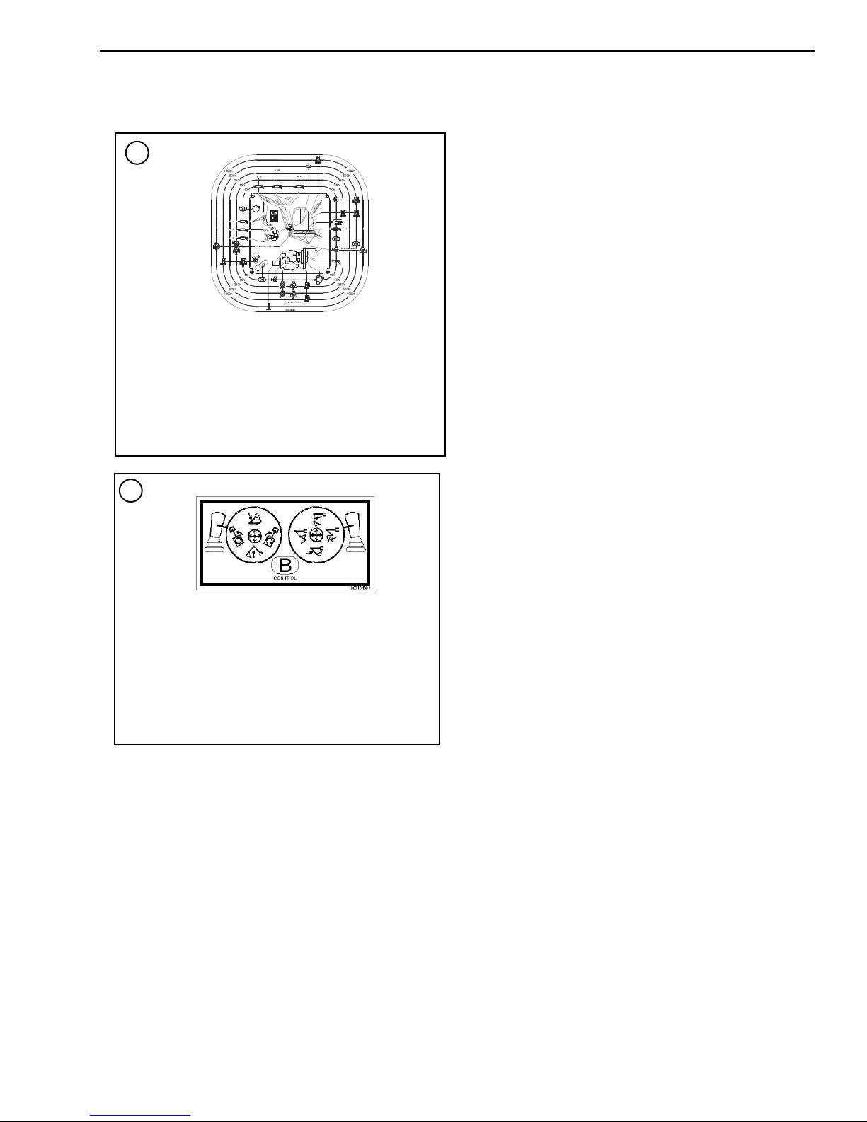
-
20
Maintenance Decal
Located on the back window of the cab.
Provides main t enance intervals quick-refer ence.
Read the operator’s manual before maintenan ce on
the machine. Refer to “Ma in te n ance Schedule” on
page 4-5..
22
Operator Controls Decal
Located on the ceiling inside the cab.
Provides quick-referenc e fo r th e I S O operator’s
control option inside the cab.
Read the operator’s manual before operating the
machine. Refer to the ope rator’s manual for
details about the operator’s controls.
KF
K
-
KP
-
KF
K
-
KF
K
-
KF
K
-
KF
K
0
-
KF
K
918070/FP0811 2-15 Printed in U.S.A.
Page 44

ANSI-Style Safety Decal Locations (Serial Numbers AH02282 and Before)
PN 161985
PN 161966
PN 161986
Danger Zone Warning Decal
To Avoid Injury Warning Decal
Hydraulic Oil Warning Decal
Printed in U.S.A. 2-16 918070/FP0811
Page 45

Cab Ceiling Decals To Avoid Injury Warning Decal (Cab Only)
PN 177443 PN 177444
PN 163976 PN 163973
PN 164854
PN 163975 BOTH SIDES
Warning Avoid Injury or Death Decal
918070/FP0811 2-17 Printed in U.S.A.
Page 46

Entanglement Hazard, Rotating Fan, and Hot
PN 163977
PN 163978
PN 161987
PN 177441
PN 161965
Surface Decals
To Avoid Injury or Death Decal
Diesel Warning Decal
Printed in U.S.A. 2-18 918070/FP0811
Page 47

CHAPTER 3 – OPERATION
WARNING
OPERATING CONTROLS
• Read and understand this entire manual. Follow warnings and instructions
for operation and maintenance. Failure
to follow instructions can result in injury
or death.
• Read and understand all safety decals
before operating the machine. DO NOT
operate the machine unless all factoryinstalled guards and shields are in
place.
• Be sure you are familiar with all safety
devices and controls before operating
the machine.
• Know how to stop the machine before
starting.
• Use only with GEHL Company approved
accessories or referral attachments.
GEHL Company cannot be responsible
for safety if the unit is used with nonapproved attachments.
Machine Orientation
Guards and Shields
Whenever possible, guards and shields are used to protect potentially hazardous areas on the machine. In
many places, decals are also provided to warn of potential hazards or to display special operating procedures.
See Chapter 2 – Safety.
The left operator’s console should be raised to enter
and exit the cab. In the raised position, the console
locks out all hydraulic functions of the machine. See
Figure 3-1.
• Check for correct function after adjustments or maintenance.
Figure 3-1 Operator’s Left Console in Lock-out
Position
918070/FP0811 3-1 Printed in U.S.A.
Page 48

Figure 3-2 Equipment and Controls
9
1
2
23
25
24
26
27
22
20
4
19
21
28
8
17
14
12
11
15
16
15
10
13
18
7
3
6
5
Model 503Z/603 -- Serial Numbers AJ02993 and Up
Printed in U.S.A. 3-2 918070/FP0811
Page 49

Pos.
Description For more information see page
1 Auxiliary Hydraulics Pedal Cover............................................................................................................................................................3-18
2 Auxiliary Hydraulics Pedal....................................................................................................................................................................... 3-18
3 Joystick (left)...........................................................................................................................................................................................3-17
4 Joystick (right) - optional proportional auxiliary hydraulic joystick shown................................................................................................3-17
5 Control Lever Base (left)
6 Control Lever Base (right)
7 Armrest (left)
8 Armrest (right)
9 Seat Horizontal Adjustment Lever...........................................................................................................................................................3-19
10 Air Vent (cab only, rear window / left)
11 Air Vent (cab only, rear window / right)
12 Radio (option)
13 Seat Backrest Adjustment.......................................................................................................................................................................3-19
14 Seat Belt Latch........................................................................................................................................................................................3-19
15 Cup Holder
16 Document Storage Box
17 Switch Panel.............................................................................................................................................................................................. 3-9
18 Throttle Lever..........................................................................................................................................................................................3-18
19 Fuse Box...................................................................................................................................................................................................1-6
20 Preheating/Ignition Switch.......................................................................................................................................................................3-13
21 Accessory Power Outlet
22 Instrument Cluster
23 Drive Pedal (left)......................................................................................................................................................................................3-14
24 Drive Pedal (right) ...................................................................................................................................................................................3-14
25 Drive Lever (left)......................................................................................................................................................................................3-14
26 Drive Lever (right).................................................................................................................................................................................... 3-14
27 Dozer Blade Pedal/Lever ........................ ............. ...................................................................................................................................3-18
28 Heater Control (cab only) ........................................................................................................................................................................3-24
918070/FP0811 3-3 Printed in U.S.A.
Page 50

Figure 3-3 Equipment and Controls
4
8
17
13
11
6
12
14
1
3
2
5
10
9
7
15
16
25
24
26
27
23
21
19
20
18
28
29
Model 603 -- Serial Numbers AH00579 to AH02282
Printed in U.S.A. 3-4 918070/FP0811
Page 51

Figure 3-4 Equipment and Controls
4
8
7
13
11
6
12
14
1
3
2
5
10
9
7
15
16
25
24
26
27
22
23
21
19
20
18
28
29
Model 503Z -- Serial Numbers up to AH02282; Model 603 -- Serial Numbers AH00578 and Before
918070/FP0811 3-5 Printed in U.S.A.
Page 52

Pos.
Description For more information see page
1 Auxiliary Hydraulics Pedal Cover.............................................................................................................................................................3-18
2 Auxiliary Hydraulics Pedal .......................................................................................................................................................................3-18
3 Joystick (left)............................................................................................................................................................................................3-17
4 Joystick (right) - optional proportional auxiliary hydraulic joystick shown................................................................................................3-17
5 Control Lever Base (left)
6 Control Lever Base (right)
7 Armrest (left)
8 Armrest (right)
9 Seat Horizontal Adjustment Lever ...........................................................................................................................................................3-19
10 Air Vent (cab only, rear window, on the left)
11 Air Vent (cab only, rear window, on the right)
12 Radio (option)
13 Seat Backrest Adjustment........................................................................................................................................................................3-19
14 Seat Belt Latch.........................................................................................................................................................................................3-19
15 Cup Holder
16 Bracket (storage box for documents)
17 Switch Panel..............................................................................................................................................................................................3-9
18 Throttle Lever...........................................................................................................................................................................................3-18
19 Fuse Box....................................................................................................................................................................................................1-6
20 Preheating/Ignition Switch .......................................................................................................................................................................3-13
21 Accessory Power Outlet
22 Coolant Temperature Indicator
23 Instrument Cluster
24 Drive Pedal (left)......................................................................................................................................................................................3-14
25 Drive Pedal (right)....................................................................................................................................................................................3-14
26 Drive Lever (left) ......................................................................................................................................................................................3-14
27 Drive Lever (right)....................................................................................................................................................................................3-14
28 Dozer Blade Pedal/Lever.......................................... ............. ............. .....................................................................................................3-18
29 Heater Control (cab only).........................................................................................................................................................................3-24
Printed in U.S.A. 3-6 918070/FP0811
Page 53

Figure 3-5 Instrument Panel, Switches and Indicat ors
32
31
35
30
38
34
40
51
38
50
38
36
37
38
33
41
42
43
44
45
46
47
49
49
48
52
Model 503Z/603 -- Serial Numbers AJ02993 and Up
3PD
2PD
DP1
KMH
MPH
D
01PD
9P
8PD
7PD
6PD
5PD
4PD
51PD
61P
71PD
D
81PD
91PD
02P
D
12PD
22P
D
32PD
DP24
!
!
918070/FP0811 3-7 Printed in U.S.A.
Page 54

Pos.
Description
30 Hydraulic oil filter indicator (red) – Hydraulic oil filter indicator light comes on when hydraulic oil filter is too restricted.
31 Air filter indicator (red) – Air filter indicator light comes on when air filter is too dirty.
32 Battery charge fault indicator (red) – Battery charge indicator light comes on when the ignition is turned on and goes off when the engine
starts. If the indicator light comes on while the engine is running, the battery is not charging, indicating a faulty charging circuit in the alternator or problems with the V-belt. NOTE: a faulty V-belt affects cooling pump operation, which can lead to overheating and more serious engine
problems. Shut off the engine IMMEDIATELY and determine the cause if this indicator comes on when the engine is running.
33 Engine oil pressure indicator (red) – Engine oil pressure light comes on when the ignition is turned on, and goes out when the engine
starts. During normal operation, this indicator should remain off. The indicator will light if the engine oil pressure drops too low. If this occurs,
shut the engine off IMMEDIATELY and determine the cause of the pressure drop.
34 Coolant temperature indicator (red) – Coolant temperature indicator light comes on when coolant temperature is too high.
35 Glow plug indicator (yellow) – Glow plug indicator light comes on when the ignition key is in the glow plug activation position. Indicator will
go out when the glow plugs have heated sufficiently to start the engine.
36 Hourmeter – Indicates the total operating hours of the machine. Use the hourmeter to track maintenance in the maintenance log.
37 Fuel level gauge – The fuel level gauge shows the amount of fuel in the tank.
38 Indicator light – Not assigned.
39 Hydraulic oil temperature indicator light – Hydraulic oil temperature indicator light comes on when hydraulic oil is too hot.
40 Coolant temperature gauge – Displays coolant temperature.
41 High-speed switch (transport speed) – Pressing the switch will enable high travel speed.
42 Windshield wiper switch (cab models only) – Pressing the two-position switch to the first position turns on the windshield wiper. Pressing
and holding the switch in the second position activates the washer fluid pump.
43 Work light switch – Press switch to the ON position to turn on the boom work light.
44 Roof lights (option) – Press switch to the ON position to turn on the roof light lights.
45 Rotating beacon (option) – Press switch to the ON position to turn on the rotating beacon.
46 Ventilation fan (two-speed) – Press the two-position switch to turn on the ventilation fan. Pressing switch to the first position is the low fan
speed position, and the second position is the high fan speed position. If the Summer/Winter operation valve is OPEN (HEATING position),
this switch will function as the cab heater ON/OFF switch. The Summer/Winter operation valve is located under the hood on top of the engine
behind the radiator.
47 Air conditioning (option) – Press the switch to turn on the air conditioning.
48 Proportional control status indicator (option) – One flash indicates precision mode; two flashes indicate power mode.
49 Not assigned
50 High-speed indicator (option) – Indicates high-speed is enabled.
51 Engine error indicator – Indicates a “check engine” condition. See page 5-6.
52 Auto-idle switch (option) – Enables optional auto-idle feature. See page 3-19.
Printed in U.S.A. 3-8 918070/FP0811
Page 55

Figure 3-6 Instrument Panel, Switches and Indicat ors
32
31
35
30
38
34
40
51
38
50
38
36
37
38
33
41 42
43 44 45
46
47
48
49 49
52
Model 603 -- Serial Numbers AH00579 to AH02282
3PD
2PD
DP1
KMH
MPH
D
01PD
9P
8PD
7PD
6PD
5PD
4PD
51PD
61P
71PD
D
81PD
D
91PD
02P
12PD
22P
D
32PD
DP24
!
!
918070/FP0811 3-9 Printed in U.S.A.
Page 56

Figure 3-7 Instrument Panel, Switches and Indicat ors
33
34
35
39
38
30
31
32
37
36
40
38
38
41 42
43 44 45
46 47
48 49
49
Model 503Z -- Serial Numbers up to AH02282; Model 603 -- Serial Numbers AH00578 and Before
Printed in U.S.A. 3-10 918070/FP0811
Page 57

Pos.
Description
30 Hydraulic oil filter indicator (red) – Hydraulic oil filter indicator light comes on when hydraulic oil filter is too restricted.
31 Air filter indicator (red) – Air filter indicator light comes on when air filter is too dirty.
32 Battery charge fault indicator (red) – Battery charge indicator light comes on when the ignition is turned on and goes off when the engine
starts. If the indicator light comes on while the engine is running, the battery is not charging, indicating a faulty charging circuit in the alternator or problems with the V-belt. NOTE: a faulty V-belt affects cooling pump operation, which can lead to overheating and more serious engine
problems. Shut off the engine IMMEDIATELY and determine the cause if this indicator comes on when the engine is running.
33 Engine oil pressure indicator (red) – Engine oil pressure light comes on when the ignition is turned on, and goes out when the engine
starts. During normal operation, this indicator should remain off. The indicator will light if the engine oil pressure drops too low. If this occurs,
shut the engine off IMMEDIATELY and determine the cause of the pressure drop.
34 Coolant temperature indicator (red) – Coolant temperature indicator light comes on when coolant temperature is too high.
35 Glow plug indicator (yellow) – Glow plug indicator light comes on when the ignition key is in the glow plug activation position. Indicator will
go out when the glow plugs have heated sufficiently to start the engine.
36 Hourmeter – Indicates the total operating hours of the machine. Use the hourmeter to track maintenance in the maintenance log.
37 Fuel level gauge – The fuel level gauge shows the amount of fuel in the tank.
38 Indicator light – Not assigned.
39 Hydraulic oil temperature indicator light – Hydraulic oil temperature indicator light comes on when hydraulic oil is too hot.
40 Coolant temperature gauge – Displays coolant temperature.
41 High-speed switch (transport speed) – Pressing the switch will enable high travel speed.
42 Windshield wiper switch (cab models only) – Pressing the two-position switch to the first position turns on the windshield wiper. Pressing
and holding the switch in the second position activates the washer fluid pump.
43 Work light switch – Press switch to the ON position to turn on the boom work light.
44 Roof lights (option) – Press switch to the ON position to turn on the roof light lights.
45 Rotating beacon (option) – Press switch to the ON position to turn on the rotating beacon.
46 Ventilation fan (two-speed) – Press the two-position switch to turn on the ventilation fan. Pressing switch to the first position is the low fan
speed position, and the second position is the high fan speed position. If the Summer/Winter operation valve is OPEN (HEATING position),
this switch will function as the cab heater ON/OFF switch. The Summer/Winter operation valve is located under the hood on top of the engine
behind the radiator.
47 Air conditioning (option) – Press the switch to turn on the air conditioning.
48 Proportional control status indicator (option) – One flash indicates precision mode; two flashes indicate power mode.
49 Not assigned
50 High-speed indicator (option) – Indicates high-speed is enabled.
51 Engine error indicator – Indicates a “check engine” condition. See page 5-6.
52 Auto-idle switch (option) – Enables optional auto-idle feature. See page 3-19.
918070/FP0811 3-11 Printed in U.S.A.
Page 58

Excavator Components
8
1. Fuel water separator
2. Battery disconnect switch (All Model 603; Model
503Z - serial numbers AH00579 and up)
3. Air cleaner
4. Fuel filter
5. Engine oil filter
6. Engine oil dipstick
7. Engine oil fill
8. Heater on/off valve (cab only serial numbers
AD04650 and before)
9. Locking fuel filler cap
10. Hydraulic fluid filler cap
11. Hydraulic fluid level sight gauge
12. Radiator
13. Radiator overflow reservoir
14. Radiator cap
15. Windshield washer reservoir (cab only)
16. Hydraulic oil cooler
17. Air conditioning condenser (option, cab only)
18. Battery (503Z up to serial numbers AH02282
shown; Model 603 and 503Z machines with serial
numbers AJ02993 and up battery is located under
cab)
Figure 3-8 Excavator Components
Printed in U.S.A. 3-12 918070/FP0811
Page 59

Ignition Key Switch
0
P
I
II
III
1
3
2
1
3
2
1
3
2
Model 503Z -- Serial Numbers AH00579 to AH02282
Model 603 -- Serial Num bers AH00579 and up
Model 503Z -- Serial Numbers A J 02993 and up
Model 603 -- Serial Numbers AH00578 and before
Battery Disconnect Switch
Note: The engine can only be started if the left control
lever console is pivoted down into the operation position.
With the key in the fully counter-clockwise “P” position, all power is shut off. The key can be inserted or
removed when the switch is in this position.
With the key in the “0” position, power to the accessory circuit is turned on. The key can be inserted or
removed when the switch is in this position.
With the key in the “I” position, power is turned on to
all controls and electrical circuits. The battery charge
indicator light and the oil pressure indicator light will
come on.
With the key in the “II” position, the glow plug indicator will come on while the glow plugs warm intake air
in cold weather.
With the key turned fully clockwise “III” and held in
position, the engine will crank/start and the indicator
lights should go out. Release the key after the engine
starts (the key returns to the “I” position when it is
released after starting the engine).
A battery disconnect switch is located in the engine
compartment under the hood. The switch allows electrical lock out of all functions of the excavator. See
Figure 3-10. To disconnect battery and lock out all
electrical functions, turn key (1) of the battery disconnect switch to position (2) and remove it. To reconnect
battery and turn on all electrical functions, insert key
(1) into the battery disconnect switch and turn down to
the notched position (3).
Note: The key must always be returned to the “I” position between attempts to start the engine in order to
activate the glow plug system.
Figure 3-9 Ignition Key Switch
918070/FP0811 3-13 Printed in U.S.A.
Figure 3-10 Battery Disconnect Switch
Page 60
Travel Controls
WARNING
WARNING
• Levers and controls should return to
neutral position when released.
• Be sure the levers and controls are in
the neutral (middle) position before
starting the engine.
• Operate controls gradually and
smoothly. Excessive speed and quick
control movements without regard for
conditions and circumstances are hazardous and could cause an accident.
Be sure that the dozer blade is “in front.”
When the operator’s cab is facing forward,
the blade will be visible and travel controls
will operate as expected. If the dozer blade
is not visible, the operator’ s cab is facing to
the rear, and the travel controls will operate
in reverse.
Figure 3-11 Travel Controls
Spin Turn
Move the levers in opposite directions to spin the
machine on its axis. To spin turn left, move the right
control lever forward while pulling the left control
lever to the rear; to spin turn right, move the left control
lever forward while pulling the right control lever to
the rear. See Figure 3-11.
Forward Travel
Push both travel control levers or pedals forward. The
farther these are moved, the faster the machine will
travel. See Figure 3-11.
Reverse Travel
Pull both travel control levers or pedals back. The farther these are moved, the faster the machine will travel.
See Figure 3-11.
Turning During Travel
Move one control lever or pedal farther than the other
one. To turn left while moving forward, move the right
control lever farther forward; to turn right while moving forward, move the left control lever farther forward. See Figure 3-11.
Printed in U.S.A. 3-14 918070/FP0811
Page 61

Tilting the Cab or Canopy
WARNING
2
1
3
4
5
7
6
8
9
11
10
11
• Always tighten cab lock-down nuts
before driving or using the machine.
• Always close the cab door before tilting
the cab.
• Stay clear from underneath the cab as it
is tilted.
• Always secure the tilt rod in the support
position the when cab is tilted.
5. Reinstall the cab lock-down nuts (2) and (3).
6. Place the jack handle tubes (4) back in the tool kit.
Refer to items 1—10 in Figure 3-12 to safely complete
the following procedure.
Tilting the cab or canopy up:
1. Follow “Mandatory Safety Shutdown Procedure”
on page 2-2.
2. Raise the floor mat (1) on the right, front of the cab
and remove cab lock-down nut (2). Remove cab
lock-down nut (3) at the right rear of the cab.
3. Securely close the cab door.
4. Locate the jack handle tubes (4) from the tool kit in
the engine compartment, insert them into the jack
(5) and jack to the limit. The cab will be raised as
far as the jack (5) will travel.
5. Pull on handle (7) until the cab is completely tilted
and supported by the safety cable (8).
6. Remove the tilt rod (9) from the storage bracket
(10) and slide the tilt rod (9) into the guide bracket
(11) and secure with the retention pin.
Tilting the cab or canopy down:
1. Remove the tilt rod (9) from the guide bracket (11)
by removing the retention pin and slide the tilt rod
(10) out of the guide bracket (9) and secure with
the retention pin back in the storage bracket (10).
2. Use handle (7) to slowly lower the cab back onto
the jack (5).
3. Remove jack handle tubes (4) from the jack (5) and
insert the opposite end of the jack handle tubes (4)
onto the release pin (6). Slowly turn release pin (6)
counter-clockwise until the cab is lowered.
4. Turn the release pin (6) clockwise.
Figure 3-12 Tilting the cab or canopy
918070/FP0811 3-15 Printed in U.S.A.
Page 62

CAUTION
Check tilt rod (9), the retention pin and
5
3
5
4
2
safety cable (8) at regular intervals for
cracks and cuts. Replace defective parts
immediately.
SAE/ISO Operating Controls Selector Valve
Located on the lower left side of the chassis, under the
cab, is the SAE/ISO Selector Valve. See (1), Figure 3-
13. The SAE/ISO valve can be accessed through a cutout on the left side of the chassis at location (2). This
machine has been set at the factory for SAE standard
operation shown at position (3). If ISO operation is
desired, loosen wing nut (5) and rotate valve to position
(4) and retighten wing nut (5).
Figure 3-13 SAE/ISO Selector Valve
Printed in U.S.A. 3-16 918070/FP0811
Page 63

SAE Operating Controls
ISO Operating Controls
SAE boom and bucket functions are controlled by the
right and left joystick control levers located on the seat
consoles.
SAE Left Joystick – see Figure 3-14.
1 – Arm extend
2 – Arm retract
3 – Swing left
4 – Swing right
Figure 3-14 SAE Left Joystick
ISO boom and bucket functions are controlled by the
right and left joystick control levers located on the seat
consoles.
ISO Left Joystick – see Figure 3-16.
1 – Boom lower
2 – Boom raise
3 – Swing left
4 – Swing right
Figure 3-16 ISO Left Joystick
SAE Right Joystick – see Figure 3-15.
5 – Boom lower
6 – Boom raise
7 – Curl bucket in
8 – Curl bucket out
Figure 3-15 SAE Right Joystick
Note: The joystick controls are pilot-operated. The farther the controls are moved from center, the faster the
machine will function.
ISO Right Joystick – see Figure 3-17.
5 – Arm extend
6 – Arm retract
7 – Curl bucket in
8 – Curl bucket out
Figure 3-17 ISO Right Joystick
Note: The joystick controls are pilot-operated. The farther the controls are moved from center, the faster the
machine will function.
918070/FP0811 3-17 Printed in U.S.A.
Page 64

Boom Swivel/Auxiliary Hydraulics
1
2
Serial Numbers AH 02282 and earlier shown -- later
serial numbers simila r
1
Serial Numbers AJ02993 and up
Serial Numbers to AH02 282
1
Pedal
The boom can be swiveled without moving the swing
frame by pressing and holding the auxiliary hydraulic/
changeover valve button (1) on top of the left joystick,
and then pressing the auxiliary hydraulics pedal (2) left
or right. See Figure 3-18. Pressing and holding the auxiliary hydraulic/changeover valve button (1) and pressing the auxiliary hydraulics pedal (2) to the left with
your toe swivel the boom to the left. Pressing and holding the auxiliary hydraulic/changeover valve button (1)
and pressing the auxiliary hydraulics pedal (2) to the
right with your toe swivels the boom to the right.
The auxiliary hydraulics pedal (2) allows use/control of
front end attachments. Action will vary depending on
the attachment and how it is connected.
Dozer Blade
The dozer blade is controlled by the dozer control
pedal/lever (1) located next to the travel controls. See
Figure 3-19.
• Push control pedal/lever forward to lower the blade.
• Pull control pedal/lever rearward to raise the blade.
Figure 3-19 Dozer Blade Controls
Figure 3-18 Boom Swivel
Printed in U.S.A. 3-18 918070/FP0811
Page 65

Throttle Lever
Models 503Z/603 -- S er ia l Numbers AH00578 and before
Model 603 -- Serial Numbers A H 0 0579 to AH02282
1
1
Models 503Z/603 -- Serial Numbers AJ02993 and Up
1
Model 503Z/603 -- Seri al N umbers AJ02993 and Up
Model 503Z/603 -- Serial Nu m bers AH00611 to AH02282
1
1
Optional Auto-Idle Feature
The engine speed is controlled by the throttle lever (1)
In machines with serial numbers AJ02993 and up. the
throttle is located behind the left armrest; in machines
up to serial numbers AH02282, the throttle is located
next to the right joystick. See Figure 3-20.
• Push throttle lever (1) forward to decrease engine
speed.
• Pull throttle lever (1) rearward to increase engine
speed.
Model 603 Standard; Model 503Z Option
Serial Numbers AH00645 and Up
Press switch (1) to enable the auto-idle feature.
When the auto-idle feature is enabled, engine speed is
automatically lowered to idle when no hydraulic functions occur for five seconds. Engine speed resumes
when a hydraulic function is activated.
Figure 3-20 Throttle Lever
Figure 3-21 Auto-Idle Switch
918070/FP0811 3-19 Printed in U.S.A.
Page 66

Operator’s Seat Adjustments
1
Model 503Z/603 -- Serial Numbers AJ02993 and up
shown -- earlier serial num bers similar
2
3
4
5
7
1
Serial Numbers to
AH02282
Serial Numbers
AJ02993 and up
3
4
2
4. Backrest Adjustment
Note: The operator’s seat left console must be raised
in order to exit the cab. In the lowered or work position, all operational functions are activated, and operator exit is blocked by the Warning Arm/Lever. In the
raised position, the all hydraulic functions of the
machine are locked out.
Note: Not all serial number machines are equipped
with all seat adjustment options
The backrest adjustment lever (5) allows the operator to move the backrest forward and rearward.
5. Headrest Adjustment
The headrest adjustment (6) allows the operator to
move the headrest up and down.
6. Seat Height Adjustment
The seat height adjustment allows the operator to
move the seat height up and down. To raise the seat
height, grasp the seat and lift up until you hear an
audible click. To lower the seat, raise the seat to the
highest position and then lower the seat to its lowest position.
7. Horizontal Suspension
When horizontal suspension is turned on, shocks
from travel motion are absorbed by the seat suspension.
Arm rests
Serial Numbers AJ02993 and Up: To adjust, hold armrest (2, Figure 3-23) and pull out latch (3). Move the
armrest to the desired position and release latch (3).
Make sure latch (3) locks securely into a detent in the
armrest.
Figure 3-22 Seat Adjustment – Cab Shown
1. Seat Suspension Adjustment
Rotate the knob (1) to adjust the seat suspension
for the operator’s weight. An indicator on the front
of the seat base shows the weight adjustment in
kilograms. (1 kg = 2.2 lbs.) Adjust the seat suspension correctly to ensure a comfortable ride. See
Figure 3-22.
2. Horizontal Seat Adjustment
The seat adjustment lever (2) allows the operator to
move only the seat forward and rearward.
3. Horizontal Seat & Control Adjustment
move both the seat and the controls forward and
The seat adjustment lever (3) allows the operator to
rearward.
Printed in U.S.A. 3-20 918070/FP0811
Serial Numbers AH02282 and before: To adjust, turn
the adjustment wheel (4).
Note: The rear of the left armrest has a turnbuckle that
may need to be adjusted to allow the left armrest to
rotate out of the way when the left console is raised.
Use the turnbuckle to adjust the armrest so it does not
contact the left control lev er wh en rais ing t he left console to the lock-out position.
Figure 3-23 Armrests
Page 67

Seat Belt
WARNING
D
C
A
B
WARNING
CAUTION
CAUTION
Ventilation
ALWAYS fasten the seat belt securely and
properly. Never operate the machine without the seat belt fastened around the oper ator.
Keep the seat belt clean because dirt can
impair seat belt operation. Check seat belt
condition regularly and have damaged or
worn belts immediately repaired by an
authorized workshop.
After an accident the seat belt strap is
stretched and must be replaced with a new
strap installed by an authorized workshop.
Make sure the seat belt is not twisted when it is
fastened, and that it is fastened over the hips and not
the stomach.
Fasten the seat belt tightly and securely. Remove hard,
edged or fragile objects from your pockets or clothes
that might lie between the seatbelt and your body.
Never use ether starting aids. Glow plugs
are used for cold weather star ting. The glow
plug can cause ether or other starting fluid
to detonate, causing injury.
Windshield – Optional Cab
When the windshield is opened, be sure
both latches are locked. When closing the
windshield, keep hands on the handles and
away from path of the windshield.
The windshield can be opened for ventilation. Squeeze/
turn latches (1, Figure 3-25) located at the upper corners of the windshield. Grasp the handles (2) and pull
the windshield up until the latches lock in the open
position.
Serial Numbers AJ02993 and Up
Fastening/Unfastening the Seat Belt
Fasten the seat belt around your hips and waist and
insert tab (A, Figure 3-24) into buckle (B) until it clicks
securely in place. Slack in the seat belt should
automatically retract into seat belt spool (D).
Unfasten the seat belt by pressing button (C).
Figure 3-24 Seat Belt
The windshield can opened for ventilation. Squeeze
latches (1, Figure 3-25) located at the upper corners of
the windshield, pull/push the top of the windshield
backwards/forward and release latches. Pull/push the
top of the window until the catch locks the top of the
windshield securely in place.
To close the windshield, squeeze/turn the latches and
then lower the windshield. Lock the latches in the
closed position.
Support the windshield when releasing it
from the ceiling catches to avoid possible
head injury.
For additional ventilation, the lower portion of the
windshield can be removed and securely stored in the
glass holder (3) located on the rear window.
918070/FP0811 3-21 Printed in U.S.A.
Page 68

Before closing the windshield, first re-install (if
3
3
Serial Numbers AC02975 and before
1
2
1
1
2
Serial Numbers AC02976 and up
1
1
removed) and lower the bottom windshield (See “Movable Bottom Window – Optional Cab” on page 3-22).
Close the windshield by squeezing/turning the latches,
and then lower the windshield and lock the latches in
the closed position.
Figure 3-26 Side Window Operation
Movable Bottom Window – Optional Cab
Serial Numbers AJ02993 and Up
Squeeze both latches (1, Figure 3-27) on the left and
right and slide the window at both latches to open or
close. Release latches and make sure the window locks
securely open/closed.
Figure 3-25 Windshield Latches
Side Window – Optional Cab
Squeeze button (1, Figure 3-26) and slide the window
to open. Release button (1) when the window is in the
desired position. Make sure the window lock securely
in one of the recesses.
Printed in U.S.A. 3-22 918070/FP0811
Figure 3-27 Lower Front Window Operation
Note: If the lower front window is raised all the way
into the wind shield frame, it will move with the windshield as a unit if the windshield is raised for ventilation.
Serial Numbers up to AH02282
Page 69

The lower front window can be removed and securely
IMPORTANT
1
Model 503Z/603 -- Serial Numbers AH02282 and earlier
shown -- later serial numbers similar
stored in the glass holder (3, Figure 3-25) located on
the rear window.
Re-install the lower window before lowering
the windshield.
Cab Door Latch Release – Optional Cab
When fully opened, the left cab door will lock in position to the side of the cab. To release the latch, use the
black knob (1) located on the inside of the door. See
Figure 3-28.
Figure 3-28 Cab Door Latch Release
Interior Light
The interior light is located on the back of the cab
above the rear window. Press the switch to the right or
left to turn the light ON. Move the switch to the center
position to turn the light OFF.
Figure 3-29 Interior Light
Tool Kit and Cab Jack Handle
The machine tool kit and the cab jack handle are
located in the storage area under the hood in the engine
compartment.
918070/FP0811 3-23 Printed in U.S.A.
Page 70

Cab Heat Control – Optional Cab
During the colder months, the operator’s cab heater can
be turned on by rotating the dial near the vent (Figure
3-30). On older models, turn on the cab heater by opening the heater valve located under the hood on top of
the engine behind the radiator (Figure 3-31). Rotate the
lever to either the “heat on” or “heat off” position as
required.
Note: The recirculated air mode vent is a storage
compartment on the canopy model machines.
Recirculated Air Mode
When heating or cooling the cab, the recirculated air
mode can be utilized to heat or cool only the air in the
cab with no fresh air supply from the outside. Sliding
the plate to the left will turn ON the recirculated air
mode by closing the vent. Sliding the plate to the right
will turn OFF the recirculated air mode by opening the
vent. Figure 3-32 shows the unit with recirculated air
mode turned OFF.
Figure 3-32 Recirculated Air Mode
Figure 3-30 Cab Heat Control - SN AD04651
and Up
Figure 3-31 Cab Heat Control - SN AD04650
and Before
Printed in U.S.A. 3-24 918070/FP0811
Page 71

Preheated Fresh Air
WARNING
IMPORTANT
Selection of “cold” or “preheated” fresh air in winter.
Mounting/Removing Buckets
ALWAYS wear protective goggles, helmets, gloves,
steel-toed shoes, etc.
DO NOT service the bucket while the engine is
running.
DO NOT stand behind the bucket when removing the
pins.
DO NOT use your hands or fingers to align the bucket
and dipper arm holes.
ALWAYS verify the bucket is safely locked before
starting the engine and resuming operation.
Figure 3-33 Fresh Air
A deflector plate on the heater baffle can be set to two
different positions:
• Fresh air-heater takes in air from outside the cab.
See Figure 3-33.
• Preheated fresh air-heater takes in air from the chassis. See Figure 3-34.
Figure 3-34 Preheated Fresh Air
• DO NOT use a hammer directly on a
securing pin to loosen it. The pounding
may cause splintering, which may lead
to serious injury.
• The bucket can crush hands or feet. DO
NOT use your hands or feet as
substitutes for the correct equipment.
Removing A Bucket
1. Lower the bucket to the ground with the flat side
facing down (1, Figure 3-35).
Place the bucket against the ground with
minimum pressure. More pressure increases resistance, which will make it more
difficult to remove the pins.
2. Stop the engine.
Change from fresh air to preheated fresh air as follows:
• Tilt the cab. See “Tilting the cab or canopy” on
page 3-15. The deflector plate is located on the
heater under the cab.
• Loosen both attachment screws.
• Reposition and fit the deflector plate back on again.
• Tilt the cab back down again and secure it.
918070/FP0811 3-25 Printed in U.S.A.
3. Remove the two lynch pins (2A and 2B, Figure 3-
35).
Page 72

Attaching A Bucket
3
2
1
2A
3B
3A
2B
WARNING
IMPORTANT
1. Grease the dipper arm and bucket holes.
2. Since the bucket is on the ground and stationary,
maneuver the machine until the dipper arm holes
align flush with the bucket holes.
DO NOT use your hands or fingers to align
the bucket and dipper arm holes.
3. Stop the engine.
4. Insert the upper securing pin first (3A, Figure 3-
35). If needed, use a hammer and brass punch to
gently tap the pin through the hole. Insert a lynch
pin (2A, Figure 3-35) through the hole in the pin
and lock.
Figure 3-35 Bucket Removal/Mounting
4. Remove the lower securing pin first (3B, Figure 3-
35) and then the other (3A). Carefully remove the
pins with a hammer and brass punch if they are
stuck. Once pin 3B is removed, pin 3A might have
more pressure applied against it, making it difficult
to remove. If this happens:
a. Start the engine.
b. Slightly raise and lower the boom to relieve
c. Turn off the engine.
d. Try removing the pin again, using a hammer
pressure from the pin.
and brass punch if needed.
The flat side of each securing pin head
must align with the flat guide on each side
of the hole; see 3A and 3B in Fi gure 3-27 for
how the pins look when properly installed.
5. Insert the lower securing pin (3B, Figure 3-35). If
needed, use a hammer and brass punch to gently
tap the pin through the hole. Insert a lynch pin (2B,
Figure 3-35) through the hole in the pin. Lock the
lynch pin securely in place.
6. Verify the bucket is locked and secure before
starting the engine and resuming operation.
Printed in U.S.A. 3-26 918070/FP0811
Page 73

Auxiliary Hydraulics Connections
IMPORTANT
1
2
3
2
4
3
5
6
Follow the instructions in the operator’s
manual from the attachment manufacturer
for connecting the attachment to the
machine’s auxiliary hydraulics machine’s
auxiliary hydraulics.
Figure 3-36 shows the three quick connections on the
dipper arm meant for auxiliary hydraulics, which are
for the following:
• 1: Pressure line (male connector)
• 2: Large return line (female connector)
• 3: Pressure line (female connector)
7. To connect each coupling:
a. If necessary, rotate lock sleeve (2, Figure 3-37)
so notch (3) aligns with lock ball (4).
b. Pull lock sleeve (2) down in the direction of
arrow (5).
c. Insert the attachment coupling into the corre-
sponding auxiliary hydraulics connection coupling.
d. Release lock sleeve (2) so it snaps into place
and locks the couplings together. Verify the
lock sleeve (2) is snapped closed and the coupling is securely locked together.
e. Twist lock sleeve (2) so notch (3) is NOT
aligned with lock ball (4), to help prevent accidental de-coupling.
Disconnecting the Quick Couplings
1. Perform steps 1 through 6 in “Connecting the
Quick Couplings” on page 3-27 before proceeding
to the next step.
Figure 3-36 Auxiliary Hydraulics Connections
Connecting the Quick Couplings
1. Park the machine on firm and level ground.
2. Extend the dipper arm cylinder halfway and
position the boom/dipper arm so the auxiliary
hydraulic connectors are positioned as shown in
Figure 3-36.
3. Stop the engine.
4. Turn the ignition key to position 1.
2. To disconnect each coupling:
a. Pull lock sleeve (2, Figure 3-37) down in the
direction of arrow (5).
b. Listen for the hissing sound to verify that any
pressure has been released from the connection.
c. Twist lock sleeve (2) so notch (3) is aligned
with lock ball (4).
d. Push lock sleeve (2) up in the direction of
arrow (6) to disconnect the coupling.
5. Release pressure from the bucket cylinder by
moving the left control lever to the left and right.
6. Lift the left control lever base as a safety
precaution.
918070/FP0811 3-27 Printed in U.S.A.
Figure 3-37 Quick Coupling Connections
Page 74

MACHINE OPERATION
WARNING
IMPORTANT
IMPORTANT
WARNING
• Read and understand this entire manual. Follow warnings and instructions
for operation and maintenance. Failure
to follow instructions can result in injury
or death.
• Read and understand all safety decals
before operating the machine. DO NOT
operate the machine unless all factory
installed guards and shields are in
place.
• Be sure you are familiar with all safety
devices and controls before operating
the machine.
• Know how to stop the machine before
starting.
• Use only with approved accessories or
referral attachments. Manitou Americas, Inc. cannot be responsible for
safety if the unit is used with nonapproved attachments..
• Clean engine area of any flammable materials.
• Engine oil level (fill as required) (page 4-9)
• Hydraulic system for leaks
• Hydraulic oil level (fill as required) (page 4-9)
• Pivot points for proper operation
• Track tension and condition (page 4-23)
• Windshield washer reservoir level (cab machines
only) (page 4-26)
• Lights, signals, indicators warning lights and indicator lights
• Attachment safely locked onto machine and attachment condition
• V-belt condition and tension (page 4-22)
• Lubrication points lubricated
• Broken and loose parts (repair as required)
• Engine cover securely latched
• Fuel level (page 4-11)
• Check for correct function after adjustments or maintenance.
Pre-Operation Checklist
See the list of recommended lubricants in
“Fluid Capacities/Lubricants” on page 1-4
for proper grade of engine oil and hydraulic
oil. Only use oils specified on the list. specified on the list .
Check the following items at the beginning of each
work day or every 12 working hours:
• Seat belt and mounting hardware
• Safety decals (replace as required) (page 2-10)
• Air cleaner and intake hoses (page 4-10)
• Engine coolant level and system for leaks (page 4-
14)
Do not run the engine until the fuel tank is
completely empty. If this happens, air will
enter the fuel system, and the fuel system
will have to be bled. Always fill the tank with
fuel at the end of the working day. with fuel
at the end of the working day.
Never use ether starting aids. Glow plugs
are used for cold weather star ting. The glow
plug can cause ether or other starting fluid
to detonate, causing injury.
Engine Start and Stop
Note: When all machine controls are stationary (no
pilot control pressure), the swing motor and travel
motor brakes are automatically applied. When any
control is activated, the appropriate brake is automatically released.
Note: All hydraulic functions are locked out with the
operator’s seat left console in the raised position.
Printed in U.S.A. 3-28 918070/FP0811
Page 75

Engine Start Procedure
DANGER
WARNING
IMPORTANT
IMPORTANT
DO NOT run the engine in an enclosed area
without proper ventilation. Be sure there is
adequate fresh air if running the machine in
an enclosed area.
Indicator lamps should go out when the
engine starts. If they do not, turn the engine
off IMMEDIATELY. Do not use machine until
the problem has been identified and
repaired.
7. Allow engine to warm up at idle speed for approximately 10 - 15 minutes to fully warm up all systems.
Ensure that bystanders are a safe distance
away from the machine before starting the
engine.
1. Adjust the operator’s seat to desired settings.
2. Fasten the seat belt.
3. Be sure all levers and controls are in the neutral
positions.
4. Make sure no one is dangerously close to the
machine.
5. Insert the ignition key into the switch and turn it
clockwise to the (II) position. Indicators for oil
pressure and battery voltage should light. In cold
weather, the glow plug indicator will come on
while the glow plugs warm the engine.
6. Turn the key fully clockwise and hold it until the
engine starts, and then release the key.
Note: The key must be returned to the (I) position
between attempts to s tart the eng ine in order to activat e
the glow pl ug system.
8. Test the drive pedals and control levers and check
for proper operations before working with the
machine.
Cold Weather Engine Starting Procedure
Note: Install an in-block or tank style engine heater
that will keep engine block and oil warm for easier
cold weather starting.
Note: Be sure engine oil is correct type and viscosity
for the ambie nt (air) tempera ture.
Note: Be sure battery is fully charged.
1. Follow all steps under “Engine Start Procedure”
above.
2. Advance the throttle to 1/4 engine speed for a
faster warm up.
3. As the engine warms up, move the throttle lever to
the idle position.
After Starting/During Operation
Check the following after startup and during operation.
Stop the engine and fix problems before continuing
operation.
Do not activate the starter motor for longer
than 20 seconds during each starting
attempt. If the engine does not start, turn
the key fully counter-clockwise, wait 30 seconds, and then attempt to start the engine
again.
918070/FP0811 3-29 Printed in U.S.A.
1. Warning indicator lights on?
2. Travel drive/steering operating properly?
3. Boom, dipper, cab rotation and bucket controls
operating properly?
4. Engine exhaust excessively smoky?
Page 76

Engine Shut Down
WARNING
Mandatory Safety Shutdown Procedure
Before leaving the machine:
Travel
1. Bring the machine to a complete stop on a level
surface. Avoid parking on an incline or a hillside,
but if this is not possible, park across the slope.
2. Lower the working equipment to the ground and
support it securely.
3. Run the engine at idle speed for a few minutes to
allow systems to cool after operation at full speed.
4. Turn the key fully counter-clockwise to shut off the
engine. Wait for all movement to stop.
5. Move the joysticks in all directions to verify the
hydraulic system is de-pressurized.
6. Lock-out controls by raising left control console.
7. Remove the ignition key and take it with you. Exit
the machine using the hand-holds.
New Machine Break-in Procedure
A new machine requires reduced operational speed
during the first 50 operating hours to properly break in
various parts. If the machine is subjected to hard use
during the break-in period, damage to operating systems may occur.
Perform the following when operating a new machine:
• Before operating the travel levers, be
sure that you know in which direction
the machine is pointing. If the dozer
blade is not visible from the operator’s
cab, you are looking at the rear of the
machine and the travel controls will be
the reverse of normal operation.
• Before moving, be sure that ther e are no
personnel in the way of the machine.
Sound the horn to alert workers that you
are about to move the machine.
• Be sure the path is clear during travel.
• Use extreme caution when reversing
travel. Be sure there is a clear path
behind the machine.
• Operate the travel control levers
smoothly to avoid sudden starts and
stops.
• Before leaving the operator’s seat, be
sure to lock out all control systems and
shut down the engine to avoid accidental activation.
• Perform all steps in “Pre-Operation Checklist” on
page 3-28.
• Start engine and let it idle for 10 - 15 minutes so all
components and systems can warm up.
• Operate machine at about 80% of maximum loads
and speed.
• At the end of the first 100 operational hours, drain
and replace the engine oil and engine oil filter.
Printed in U.S.A. 3-30 918070/FP0811
Page 77

Travel Speed Selection
CAUTION
1
Two travel speed ranges can be selected by using the
Travel Speed Switch (1) located on the control console.
See Figure 3-38. The 503Z and 603 units use an Auto2-Speed transmission on the drive motors. This feature
enables the transmission to automatically switch from
high to low speed when it senses a load.
Travel speeds are:
• Slow Speed Maximum = 1.7 mph (2.8 km/h)
• High Speed Maximum = 2.9 mph (4.7 km/h)
The slow-speed setting should be selected
to prevent automatic up-shifts if conditions
warrant.
3. Travel straight up and down slopes; never travel
across the slope. See Figure 3-39. Extend arm and
lower boom to keep the bucket about 12” (300
mm) off the ground. If the machine starts to slide
or becomes unstable, lower the bucket to regain
control. If the engine stalls, lower the bucket, make
sure that all controls are in the neutral position and
restart the engine. See “Operating on Slopes” on
page 3-33 for more information about operating
the machine on slopes.
Figure 3-38 Travel Speed Selection
General Travel Instructions
1. Avoid sudden movements and sharp turns.
2. Travel slowly on rough, frozen, or uneven terrain.
Figure 3-39 Travel Down Slopes
4. To travel straight, push both travel control levers
(or pedals) forward (or rearward). The farther the
levers (or pedals) are moved, the faster the travel
speed.
5. Pivot (or wide) turns are made by rotating only one
track forward (or rearward). The machine will
pivot on the stationary track.
6. Spin turns are made by rotating one track forward
and one track rear. The machine will spin around
its mid-point.
7. The excavator can travel in water that comes up to
the top of the upper track rollers. Be sure that the
footing is solid so that the machine will not sink.
918070/FP0811 3-31 Printed in U.S.A.
Page 78

Machine Operation
IMPORTANT
DANGER
WARNING
Joystick Controls
Extending and retracting the cylinders (boom, arm and
bucket) are controlled by the joysticks located on the
consoles attached to the operator’s seat. See page 3-17
for control configurations.
Note: The joystick controls are pilot-operated. The farther the controls are moved from center, the faster the
machine will function.
Hydraulic Swivel Unit Brake
Swing frame rotation is sufficiently braked by moving
the control lever back to the initial position. Moving
the control lever in the opposite direction brakes the
swing frame with full hydraulic pressure.
Hydraulic swivel unit brake function is not
optimal if the hydraulic system has not
reached operating temperature.
The upper carriage’s rotation is sufficiently braked by
moving the control lever back to the initial position.
Moving the control lever in the opposite direction
brakes the upper carriage with full hydraulic pressure.
Operating Precautions
• DO NOT elevate the front end of the
tracks by use of downward pressure on
the dozer blade. This will cause the
machine to become unstable.
• DO NOT excavate underneath the
machine.
• Always be sure that there is adequate
support underneath the machine. Be
aware of conditions that could cause
the earth or foundation to collapse,
resulting in risk of injury or death.
• Do not position the machine directly
underneath structures during demolition. Falling objects or structure collapse could cause severe damage or
personal injury.
• Be sure that there is the proper clearance from overhead electrical lines.
• Be sure that all underground electrical
power and gas supply lines are clearly
marked and avoided.
Mechanical Stop Brake
A multi-disc brake integrated into the rotation drive has
an additional mechanical brake effect with a time
delay. This brake is used to stop the swivel unit from
rotating in any position.
Printed in U.S.A. 3-32 918070/FP0811
• DO NOT rest your feet on the travel pedals during normal machine operation.
Unexpected machine movement could
occur.
• On Model 603 machines, make sure there
are no obstacles in the immediate area
before rotating the swing frame because
the rear section of the swing frame protrudes over the undercarriage.
• When working close to an excavated
edge, be sure that the ground the
machine is sitting on is solid. Keep the
travel motors to the rear. See Figure 3-40.
DO NOT use machine travel or swing to provide addi-
tional breakout force when the bucket is in the ground.
Page 79

DO NOT jam bucket into the ground and use machine
IMPORTANT
WARNING
weight to provide additional breakout force.
When working on soft or muddy ground, be sure that
the machine is not sinking.
DO NOT use the bucket as a hammer or ramming
device.
When digging at maximum excavation
depth, BE SURE that the dozer blade does
not contact the boom cylinder. Damage to
the boom cylinder may occur if it contacts
the dozer blade.
Figure 3-40 Machine Position for Excavating
Figure 3-41 Level Work Area on Slope
• Travel straight up and down slopes; never travel
across the slope. See Figure 3-39. Extend arm and
lower boom to keep the bucket about 12” (305 mm)
off the ground. If the machine starts to slide or
becomes unstable, lower the bucket to regain control. If the engine stalls, lower the bucket, be sure
that all controls are in the neutral position and restart
the engine.
• When traveling down a slope, put the machine in the
position shown in Figure 3-42, control the speed with
the travel levers and the throttle controls, and reduce
engine RPM.
Operating on Slopes
• Do not travel up or across a slope
steeper than 15°. Do not travel down a
slope steeper than 25°. Keep boom centered while traveling.
• Keep attachments as low as possible
when traveling on slopes or rough terrain.
Operating on a slope is hazardous. It is recommended
to level the work area as shown in Figure 3-41. If this is
not possible, use the following guidelines:
918070/FP0811 3-33 Printed in U.S.A.
Figure 3-42 Travel Down Slope
• To achieve the best stability while excavating, lower
the dozer blade to the ground.
• Operate as slowly as possible and avoid sudden
changes in direction.
• Avoid traveling over objects such as rocks, trees,
stumps, etc.
• Stop the machine travel before moving the bucket or
dozer controls.
• Slow the work cycle. Take your time.
Page 80

• Avoid working with the tracks positioned across the
WARNING
1
Serial Numbers
AJ02993 and
after
2
slope. Position the machine with the blade downhill
and lowered.
• Avoid swinging or extending the bucket farther
than necessary in a downhill direction. If you must
swing the bucket downhill, keep the boom low and
skid the bucket along the ground.
• When working with the bucket on the uphill side,
keep the bucket as close to the ground as possible.
Unload far enough away from the excavation to prevent the possibility of a cave-in.
Cold Weather Operation
In cold weather, mud should be removed from the
machine before parking. See “Track Cleaning” on
page 4-23 for cleaning mud off of the tracks. If possible, park the machine on solid ground, or on wood
planks, to prevent the track or undercarriage from
freezing to the ground.
Operating in Water
Do not operate or immerse the machine in water higher
than the top of the upper track rollers.
Thoroughly grease the machine if it has been operated
in deep water.
Swiveling the Boom
Working with the boom swiveled to the side
reduces lifting capacity.
Overloading the bucket can cause an unstable condition and increases the possibility
of tipping the machine.
The excavator boom can be swiveled from the front
position 61º to the right and 65º to the left on the 503Z,
and 51º to the right and 75º to the left on the 603. This
allows excavation of trenches along walls, fences, etc.
See Figure 3-43.
Figure 3-43 Boom Swivel Control
Press and hold the auxiliary control button, located on
top of the left joystick. Then press the auxiliary hydraulics pedal (2, Figure 3-43) with your toe or heel. Pressing the pedal down to the left swivels the boom to the
left. Pressing the pedal down to the right swivels the
boom to the right.
Bucket controls do not change when swiveling the
boom.
Printed in U.S.A. 3-34 918070/FP0811
Page 81

Grading
WARNING
Model 503Z/603 -- Serial N um b e rs AJ02993 and Up
Model 503Z/603 -- Serial Numbers to AH02282
1
Bulldozing
• Be sure there is proper clear ance for the
front end attachments when bulldozing.
• Be sure that the front end attachments
do not contact any overhead power
lines or obstructions during bulldozing.
• DO NOT drive machine into the excavation or onto loose soil, which can cause
an unstable condition, and possible tipping of the machine.
1. Raise or lower the dozer blade using the control
lever/pedal located to the right of the travel levers/
pedals. See Figure 3-44. Move the control forward
to lower the dozer blade, rearward to raise the
dozer blade.
2. The boom must be fully raised and the bucket
curled in (up) when grading.
3. When grading, the material may be pushed away to
the front or the side.
4. Raise the dozer blade slightly if excessive resistance occurs.
5. When the blade is in position, use the travel controls to move the machine as in normal travel.
Figure 3-44 Dozer Blade Control
918070/FP0811 3-35 Printed in U.S.A.
Page 82

Excavation
IMPORTANT
1
2
3
4
The following section applies to an excavator with a
standard bucket, which is used mainly for digging into
the ground to loosen, excavate and load loose or solid
material.
Never use the excavator bucket to perform
actions other than digging, grading, loadi ng
and excavating. Damage to the excavator
could result.
• Do not use the swiveling force of the
excavator so the bucket serves as a
hammer or battering ram (1, Figure 3-
45).
• Do not lower the bucket into the ground
while rotating the upper carriage or
driving the excavator (2, Figure 3-46).
• When excavating, lower the dozer blade to the
ground to aid machine stability. Whenever possible, it is best to position the dozer blade on the
same side as the excavation.
• Do not support the weight of the machine on one
side of the dozer blade.
• Do not use the falling force of the dipper arm so the bucket serves as a hammer or pile-driver (3).
• Do not cause the excavator to tip,
bounce or fall to amplify digging or
excavating (4) force.
• Use caution when retracting the bucket to prepare
for driving or transport. Hitting the bucket into the
dozer blade might damage either attachment, especially the bucket teeth.
• The dozer blade is intended for grading only; using
it as a battering ram risks serious damage to the
blade, its cylinder and connections.
Figure 3-45 Machine Operation Exclusions
Printed in U.S.A. 3-36 918070/FP0811
Figure 3-46 Machine Operation Exclusions
Page 83

Excavating
IMPORTANT
1 2 3
6
4 5 5
4. After the bucket is sufficiently filled:
Proper Bucket Position
Move the flat side of the bucket so it is parallel to the
ground (Figure 3-47).
Positions 2 and 3 in Figure 3-47 show
improper bucket orientations while
excavating.
Position 2 forces the bucket downward into
the ground, slowing down work and
subjecting the engine and hydraulic pump
to overloading.
Position 3 forces the bucket upward toward
the ground surface, reducing productivity
because of reduced bucket loads.
a. Continue moving the dipper arm toward the
excavator.
b. Extend the dipper arm cylinder so the bucket is
tilted upward (6, Figure 3-48).
c. Raise the boom.
Figure 3-48 Proper Digging Technique
Trench Excavating
Trench excavating is most efficient when the machine
tracks are parallel to the line of the trench (Figure 3-
49). For larger trenches, excavate each side first and
then the center.
Figure 3-47 Proper and Improper Bucket Orientations
Proper Digging Technique
1. Lower the bucket into the ground (4, Figure 3-48).
2. After the bucket penetrates the ground, adjust it so
its flat side is parallel to the ground (5, Figure 3-
48).
3. Pull the bucket towards the excavator by:
a. Moving the dipper arm toward the excavator,
and
b. Lowering the boom.
918070/FP0811 3-37 Printed in U.S.A.
Figure 3-49 Efficient Trench Excavating
Page 84

When excavating in confined areas, excavate by
WARNING
1
2
rotating the upper carriage and swiveling the boom
(Figure 3-50).
Figure 3-50 Excavating Trenches Sideways
• Working alongside trenches and deep excavation
are two applications where the dozer blade might
restrict bucket movement. When working alongside trenches, lower and place the dozer blade on
the ground to avoid damage to the boom cylinder.
When deep excavating, position the machine so the
lowered dozer blade is on the opposite side of the
excavation (Figure 3-51).
Placing the dozer blade on the opposite
side of the excavation decreases machine
stability. Always consider operator safety
when operating the machine, especially
under less-than-ideal working conditions.
Loading Vehicles
When loading vehicles, consider the following:
• Whenever loading in a confined area with a limited
range of motion, position the truck so maximum
visibility is ensured for the excavator operator.
• When work conditions permit, position the truck so
the excavator can load material at the rear of the
truck instead of the sides (1, Figure 3-52). The
most effective way to load into the rear of the truck
is when the truck and excavator form a 45° angle
(2, Figure 3-52).
• Raise the boom and dipper arm to dump height just
before rotating toward the truck.
• Whenever possible, dump upwind to keep dust and
airborne debris away from the operator, and the
excavator air filters and fans.
Figure 3-51 Dozer Blade Positioning
Printed in U.S.A. 3-38 918070/FP0811
Figure 3-52 Loading Vehicles
Page 85

Transporting
WARNING
1
2
WARNING
1
1
Towing
• When towing the machine, make sure
no one is close to the towing apparatus,
or in between the vehicles. The machine
may only be towed using suitable towing equipment, in connection with suitable towing apparatus, such as a towing
coupling, hooks and eyes.
• Do not use a towing apparatus that is
kinked, twisted, or otherwise damaged.
• Do not apply high loads abruptly to the
retrieval apparatus. The towing bracket
has a maximum admissible load of 6992
lbf (3110 daN).
• The towing bracket is designed for
retrieving the machine only. Do not use
the excavator to tow other vehicles.
• Do not tow the machine if the travel
drive is damaged. Damage to the
machine cause by towing is not covered
under warranty.
The Excavator can be towed by using the towing
bracket (1). Secure a towing shackle, shackle pin and
lock (2) of adequate size to the towing bracket (1) as
shown in Figure 3-53. Tow the machine slowly and
only short distances.
Lifting the Machine
• Use a lifting device and rigging with sufficient capacity for the weight of the
machine plus any attachments
• While lifting, maintain the center-ofgravity and balance points on the
machine. See Figure 3-54.
• Do not swing the boom.
• Never lift the machine with the anyone
on-board.
Secure the lifting fixture sling to the lifting points (1)
as shown.
• Model 503Z: length L1 on the lifting sling for the
boom must be 5’, 7” (1.70 m) long; length L2 on the
lifting sling must be 12’, 11” (3.93 m) long. See Figure 3-54.
• Model 603: length L1 on the lifting sling for the
boom must be 6’, 7” (2.0 m) long; length L2 on the
lifting sling must be 15’, 0” (4.6 m) long. See Figure
3-54.
• Do not exceed rated load capacity of the lifting
machine. See “503Z General Specifications” on
page 1-9 and “603 General Specifications” on
page 1-10 for excavator weights.
Figure 3-53 Towing
918070/FP0811 3-39 Printed in U.S.A.
Figure 3-54 Machine Lifting Points
Page 86

Loading and Transporting
WARNING
1
Use only transport machines that are in proper working
order and are approved for use on public roads.
• Do not exceed the transport vehicle’s
gross weight rating and the gross axle
weight rating when loading and transporting the machine.
• The transport vehicle must have sufficient capacity for the size and weight of
the machine. See “503Z General Specifications” on page 1-9 and “603 General
Specifications” on page 1-10.
• Make sure the load does not fall short of
the minimum axle load of the steering
axle of the transport vehicle, otherwise
the transport vehicle’s steering could be
seriously affected.
6. Slowly and carefully drive the machine onto the
transport vehicle. Do not change direction while
driving on the ramps. Instead, drive down off of the
ramps, and re-align the machine with the ramps.
7. After the machine is on the transport machine,
lower the dozer blade and the bucket onto the loading surface and turn of the engine. See Figure 3-55.
8. Perform the Mandatory Safety Shutdown Procedure on page 2-2.
9. Lock the cab. Do not allow anyone to stay in the
machine.
10. Place chocks under the machine tracks and secure
the machine to prevent slipping, overturning and
moving on the transport machine.
11. Use the tie down points (1) identified by decals for
securing to the transport machine. See Figure 3-55.
Securely tie the excavator to the transport vehicle at
the front, rear and the sides.
• Adjust transport speed to the load, to
the road/traffic conditions and to the
handling of the transport vehicle. Consider all possible transport conditions
such as: heavy braking, evasive maneuvers, and uneven or rough roadways.
When using ramps to load the machine:
• Do not exceed an incline of 17° (30%). See Figure
3-55.
• Clean dirt, mud, ice and snow from the ramps and
tracks.
• Use metal loading ramps with a slip-resistant surface, and with beveled ends to prevent damage to
rubber tracks.
1. Attach ramps securely to the transport machine to
prevent them from slipping off during loading.
2. Load the machine on solid, even ground.
3. Apply the transport machine parking brake and
chock the wheels.
4. Determine the direction of the track movement
(dozer blade facing forward) before moving the
machine onto the ramps.
5. Raise the bucket and dozer blade on the excavator
high enough so they will not touch the ramps during loading.
Printed in U.S.A. 3-40 918070/FP0811
Figure 3-55 Loading and Transporting
Page 87

Secure the machine properly so it cannot slip, slide,
A
Serial Numbers
AJ02993 and
after
B
roll, tip over or fall, or cause the transport vehicle to tip
over under transport conditions. Use anti-slip bases and
linings, load-securing straps and chains, clamping
beams, protective paddings, nets, edge protectors, etc.
as needed to properly secure the load. Consider all possible transport conditions such as: heavy braking, evasive maneuvers, and uneven or rough roadways. Make
sure the load does not exceed the authorized maximum
height.
OPTIONAL CONTROLS
Proportional Auxiliary Hydraulic
Joystick Control (Option)
The proportional auxiliary hydraulic joystick control
enables the following new functions:
• Selectable two-speed variable auxiliary hydraulic
mode at startup (precision or power).
• Auxiliary hydraulic control moved to the right
joystick thumb control.
• Auxiliary hammer operation is enabled for the right
joystick trigger button control.
Note: With proportional auxiliary hydraulic joystick
control , the auxiliary hydraulic / ch ange over valve button (A, Figure 3-56) is not functional . Pedal (B) always
controls boom swivel and does not change to control
the auxiliary hydraulics if button (A) is pressed. The
auxiliary hydraulics are instead controlled using the
thumb and trigger switches installed on the new right
joystick.
918070/FP0811 3-41 Printed in U.S.A.
Figure 3-56 Auxiliary Hydraulic Changeover
Valve Button/Boom Swivel Pedal
Page 88

Two-Speed Variable Auxiliary
C
Hold Switch
to the Right
During
Startup for
Power
Mode
Hold Switch
to the Left
During
Startup for
Precision
Mode
D
Model 503Z/603 -- Serial Numbers AJ02993 and Up
Model 503Z/603 -- Serial Numbers to AH02282
D
Hydraulic Mode Selection
Upon startup, the auxiliary hydraulic system can be
placed into either the power mode, or the precision
mode. Select the appropriate mode depending upon the
job requirements.
1. Shut down the excavator.
2. To set the auxiliary hydraulics to power mode,
slide and hold the thumb switch (C, Figure 3-57)
on the right joystick to the right and start the
excavator.
3. To set the auxiliary hydraulics to precision mode,
slide and hold the thumb switch (C, Figure 3-57)
on the right joystick to the left and start the
excavator.
4. Continue holding thumb switch (C) until the proportional control indicator (D, Figure 3-58) flashes.
It will flash once when starting in precision mode;
twice when starting in power mode.
Figure 3-57 Right Joystick
Figure 3-58 Proportional Control Indicator
Note: After the excavator is started, it must be shut
down and restarted in order to change between auxiliary hydraulic modes.
Printed in U.S.A. 3-42 918070/FP0811
Page 89

Auxiliary Hydraulics Proportional
C
D
Joystick Control
When the excavator is running, use the thumb switch
(C, Figure 3-59) on the right joystick to control the
auxiliary hydraulics.
Figure 3-59 Auxiliary Hydraulics Control
Slide thumb switch (C) to the right to move the auxiliary hydraulics in one direction; slide thumb switch (C)
to the left to move the auxiliary hydraulics in the opposite direction.
Auxiliary Hydraulic Hammer Operation
Note: Use the power mode (refer to “Two-Speed Variable Auxiliary Hydraulic Mode Selection”) when operating a hydraulic hammer attachment. Maximum
performance of hammer attachments is only possible
using the power mode.
To operate an auxiliary hydraulic hammer attachment,
press and hold trigger button (D, Figure 3-60) on the
right joystick. The hammer will operate continuously
until button (D) is released.
Figure 3-60 Hammer Operation
918070/FP0811 3-43 Printed in U.S.A.
Page 90

NOTES
Printed in U.S.A. 3-44 918070/FP0811
Page 91

CHAPTER 4 – MAINTENANCE
WARNING
WARNING
WARNING
GENERAL INFORMATION
Instructions are necessary before operating
or servicing the machine. Read and understand this entire manual. Follow warnings
and instructions for operation and maintenance. Check for correct function after
adjustments or maintenance. Failure to follow instructions can result in injury or
death.
Be sure you are familiar with all safety
devices and controls before operating or
servicing the machine. Know how to stop
before starting. This machine is designed
for use only with approved accessories or
referral attachments. Manitou Americas,
Inc. cannot be responsible for safety if the
unit is used with non-approved attachments.
Care and Servicing
Care and servicing have a significant influence on the
readiness for operation and service life of the machine.
For additional service information about the engine,
see the service manual provided with the machine.
Use of lubricants that do not correspond to the manufacturer’s recommendations may invalidate warranty
claims.
More frequent servicing, other than the recommended
intervals, may be required under extreme operational
conditions (extremely dusty or hot conditions).
Always dispose of waste lubrication oils and hydraulic
fluids according to local regulations or take to a recy-
cling center for proper disposal. DO NOT pour fluids
onto the ground or down a drain.
DO NOT power wash the main hydraulic pumps and
controls, throttle solenoids and sealed bearings. High
pressure water can be forced through seals and trapped
within these components, causing premature failure.
The operating pressure settings of the hydraulic system
should only be adjusted by trained, qualified personnel.
If malfunctions are caused by unauthorized alteration
of operating pressure settings, all warranty responsibilities of the manufacturer are invalidated.
Hydraulic reservoir is under pressure.
Avoid contact with leaking hydraulic fluid
and diesel fuel under pressure. It can penetrate the skin and eyes.
918070/FP0811 4-1 Printed in U.S.A.
Page 92

Maintenance Safety
• Never service the machine without reading the
applicable instructions.
• Always lower bucket and dozer blade to the
ground before performing any maintenance.
• Use correct procedures to lift and support the
machine. Always lift the blade fully before
installing jackstands.
• Keep engine cover and hydraulic valve cover
closed except for service. Close and latch covers before operating the machine.
• Be sure to have area properly ventilated when
grinding or welding parts. Wear a dust mask.
• Exhaust fumes can kill. Exhaust system must
be tightly sealed. If working in an enclosed
area, vent exhaust to outside when engine must
be run for service.
• Never modify equipment or add unapproved
attachments.
• Before checking fluid levels, stop engine and
let cool, and then clean any flammable materials from the engine and engine compartment.
• Never service or adjust machine with the
engine running unless the service procedure
requires it.
• Avoid contact with leaking hydraulic fluid and
diesel fuel under pressure, which can penetrate
the skin and eyes. NEVER use your hands to
search for hydraulic fluid leaks; use a piece of
paper or cardboard. Escaping fluid under pressure can be invisible and can penetrate skin
and cause serious injury. If any fluid is injected
into your skin, get immediate medical attention. Injected fluid MUST be surgically
removed or gangrene may result.
• Never fill fuel tank with engine running, while
smoking or when near open flame.
• Wipe up fuel spills immediately.
• Keep body, jewelry and clothing away from
moving parts, electrical contacts, hot parts and
exhaust.
• Wear eye protection when servicing the
machine.
• Lead-acid batteries produce flammable and
explosive gas. Keep arcs, sparks, flames and
lighted tobacco away from batteries.
• Batteries contain acid, which burns eyes and
skin on contact. Wear protective clothing. If
acid contacts body, flush well with water. For
eye contact, flush well with water and get
immediate medical attention.
Printed in U.S.A. 4-2 918070/FP0811
Page 93

Maintenance Label Symbols
Symbol Assembly Explanation
General Visual check
General Lubrication instructions
Fuel system Drain condensation water
Fuel system Replace the fuel filter; clean the fuel pre-filter
Radiator Check the coolant level
Radiator Change coolant
Engine Check valve clearance; adjust if necessary
Engine Check engine oil level
Engine Change engine oil
Engine Replace oil filter
Engine Check V-belt tension
Travel drive Change final drive oil
Travel drive Check final drive oil level
Undercarriage Check track tension
Hydraulic system Check hydraulic oil level
Hydraulic system Change hydraulic oil
Hydraulic system Replace hydraulic oil filter; replace hydraulic reservoir breather filter
Radiator fins Clean radiator fins
Heating,
air conditioning
918070/FP0811 4-3 Printed in U.S.A.
Replace the cab air filter
Page 94

Maintenance Label
Printed in U.S.A. 4-4 918070/FP0811
Page 95

MAINTENANCE SCHEDULE
The following service schedule is a recommended. Maintenance work must be done at regular intervals. Failure to
perform scheduled maintenance work will result in excessive wear and early machine failures. The following service schedule is a recommended.
Check, Clean and Inspect
Service Activity Daily Every 50
Hours
Engine oil level x x
Engine coolant level x x
Hydraulic oil level x x
Inspect engine/hydraulic oil radiator
and air conditioning condenser for dirt/
debris; clean if necessary
Inspect cooling system, heating and
hoses for leaks and pressure (visual
check)
Inspect air filter for damage x x
Inspect water separator pre-filter; drain
water
Check V-belt condition and tension x x
Check exhaust system for damage x x
Gearbox oil level x x
Check battery electrolyte; fill with dis-
tilled water if necessary
Clean battery x x
Replace cab air fi lter fo r heatin g and air
conditioning
Empty diesel fuel tank
Clean water separator x x
Inspect alternator, sta rter a nd electrical
connections, bearing play and function
Preheating system and electrical con-
nections
Check engine valve clearance; set if
necessary
Fuel injection pump, injection and pres-
sure, injection nozzles and valves
Inspect pilot control valve filter/restric-
tor; clean/replace if necessary
Clean drain holes in cab/canopy x x
a
xx
xx
xx
Every 250
Hours
xx
Every 500
Hours
xx
xx
xx
xx
Every
1000
Hours
xx
xx
x
Customer Dealer
a. After emptying the tank, water must be removed and air must be purged from the fuel system before use. See “Fuel
Shut-off Valve and Water Separator” on page 4-13 and “Purging Air from the Fuel System” on page 4-13.
918070/FP0811 4-5 Printed in U.S.A.
Page 96

Check, Clean & Inspect (Cont.)
Service Activity Daily Every 50
Hours
Every 250
Hours
Every 500
Hours
Every
1000
Customer Dealer
Hours
Check tracks for cracks or cuts x x
Check track tension ; adjus t if ne cess ary x x
Inspect cylinder piston rods for damage x x
Ensure bucket and at tachment pins ar e
xx
secure and locked
Inspect hydraulic line clamps for tight-
xx
ness/damage
Clean hydraulic couplings/dirt build-up
xx
on the hydraulic system dust caps
Grease central lubrication system x x
Inspect engine cover gas strut x x
Ensure warning decals and Operator’s
Manual are in place
Check primary relief valve pressure
Check fasteners for tightness
a
a
a
Check indicator lights for correct func-
a
tion
Inspect cab/canopy tilt lock/support
components
a
Inspect insulating mats in the eng ine
compartment
a
Check bearing play on tread rollers,
xxxx
xx x
xx x
xx x
xx x
xx x
xx
track carrier rollers and front idlers
Check air filter restriction indicator x x
a. Check after first 50 hrs; every 500 hrs thereafter.
Fluid and Filter Changes
Service Activity Daily Every 50
Hours
Engine oil
Engine oil filter
Fuel filter
Hydraulic oil filter insert
Gearbox oil
x
x
x
x
x
Hydraulic oil xx
Breather-hydraulic oil tank x x
Engine coolant xx
Air filter element when indicator light
comes on
a. Change after first 50 hrs; every 500 hrs thereafter.
b. Dusty work environment, high temperature, high rate of hammer use, and similar intensive use conditions.
c. Change after first 50 hrs; every 500 hrs thereafter.
d. Change after first 50 hrs; every 1000 hrs thereafter.
a
a
c
c
d
Every 250
Hours
Every 500
Hours
Every
1000
Customer Dealer
Hours
b
x
xx
xx
xx
xx
xx
x
Printed in U.S.A. 4-6 918070/FP0811
Page 97

Cab Air Conditioning
Service Activity Daily Every 50
Hours
Test air conditioning function x x
Check dehumidifier for corrosion x x
Replace cab air filter x x
Check refrigerant x x
Replace dehumidifie r
Replace compressor oil
a
a
Every 250
Hours
Every 500
Hours
Every
1000
Hours
xx
xx
Customer Dealer
a. Replace every 1000 hrs or once every 2 years, whichever comes first.
Cab Functional Checks
Service Activity Daily Every 50
Lights, signaling system, audible warning system
Heating function
a
a
a. Operate weekly.
Hours
Every 250
Hours
xx
xx
Every 500
Hours
Every
1000
Hours
Customer Dealer
Leakage Checks
Service Activity Daily Every 50
Hours
Inspect hydraulic lines/hoses for tightness, leaking, or chafing
Engine and hydraulic system components
Cooling and heating circuit components x x
Traveling drive components x x
xx
xx
Every 250
Hours
Every 500
Hours
Every
1000
Hours
Customer Dealer
918070/FP0811 4-7 Printed in U.S.A.
Page 98

Lubrication
D = Daily
W = Weekly
D
D
D
D
D
D
D
D
D
D
W
W
W
W
W
W
W
(See Figure 4-1).
Service Activity Daily Every 50
Hours
Dozer blade x x
Swivel console x x
Boom x x
Dipper arm x x
Attachments x x
Chassis (front of undercarriage) x x
Every 250
Hours
Every 500
Hours
Every
1000
Hours
Customer Dealer
Figure 4-1 Lubrication Points
Printed in U.S.A. 4-8 918070/FP0811
Page 99

Recommended Lubricants
IMPORTANT
IMPORTANT
IMPORTANT
2
3
max
min
1
Engine Oil
Engine
Be sure to read the service manual supplied
Be sure to read the engine manual supplied
with this machine for detailed engine specifications.
See “Fluid Capacities/Lubricants” on page 1-4 for
engine oil specifications.
Hydraulic Oil
See “Fluid Capacities/Lubricants” on page 1-4 for
hydraulic oil specifications.
Swing Ring
Lubricate with a heavy-duty lithium complex grease
with 3% molybdenum disulfide, such as Chevron RPM
Heavy Duty Grease No. 2, Mobilgrease Moly 52 or BP
Energrease Moly EP2.
Final Drive Unit
An EP grade gear oil that conforms to API GL5, such
as Chevron Delo Gear 80W-90 or BP Transgear 80W90 is required.
Swing Gear Unit
An EP grade gear oil that conforms to API GL5, such
as Chevron Delo Gear 80W-90 or BP Transgear 80W90 is required.
Checking Engine Oil Level
See “Fluid Capacities/Lubricants” on
page 1-4 for engine oil grade. To prevent
damage to the engine, only use the engine
oils specified, or oils of equivalent quality
and grade could occur.
To check the engine oil, the machine must be on a level
surface with the engine turned off. Check the oil level
before starting the engine or at least five minutes after
shutting off the engine.
1. Open the engine cover.
2. Check the engine oil level using the dipstick (1)
located at front of the engine. See Figure 4-2.
3. Add oil if required through the oil filler neck (3).
See Figure 4-2.
4. Drain excess oil if required. See “Changing Engine
Oil and Filter” on page 4-10.
Lubrication Points
See Figure 4-1.
Grease all lubrications points using a heavy-duty lithium complex grease with 3% molybdenum disulfide,
such as Chevron RPM Heavy Duty Grease No. 2,
Mobilgrease Moly 52 or BP Energrease Moly EP2.
Ranges of Applications
From –13° F to +104° F (-25° C to + 40° C) outside
temperature.
918070/FP0811 4-9 Printed in U.S.A.
Figure 4-2 Oil Dipstick and Filter Locations
Note: The marks on the dipstick indicate the minimum
and maximum oil levels.
Page 100

Changing Engine Oil and Filter
IMPORTANT
IMPORTANT
2
3
1
4
5
Air Cleaner Service
1. Perform the “Mandatory Safety Shutdown Procedure” on page 2-2, but do not allow the engine to
fully cool; warm oil will drain more completely..
The machine must be postioned on a level
surface for the oil to drain completely.
2. Open the engine cover.
3. Position waste oil collection container under
engine oil pan.
4. Remove the drain plug from the oil pan and allow
oil to drain into waste oil collection container.
Dispose of waste engine oil according to
environmental laws or take to a recycling
center for proper disposal. DO NOT pour
waste engine oil onto the ground or down a
drain.
1. Perform the “Mandatory Safety Shutdown Procedure” on page 2-2,
2. The air cleaner is located under the engine cover.
Press the engine cover release button and raise the
engine cover.
3. Release the bow clips (1) to remove the air cleaner
cover and gasket (2). See Figure 4-3.
4. Carefully remove outer air cleaner element (3). See
Figure 4-3. Carefully remove inner air cleaner element (3). Clean the inside of the air cleaner housing components with a lint-free cloth. Clean all
contamination (dust) from inside the upper and
lower air cleaner housing and cover with a clean,
lint-free cloth.
5. Replace both the inner and outer air cleaner elements when the indicator light comes on or according to the maintenance schedule.
6. Reinstall air cleaner elements (3, 4), gasket and air
cleaner cover (2). Fasten bow clips (1).
7. Close and secure engine cover.
5. Remove the oil filter (2, Figure 4-2), using a filter
wrench as necessary.
6. Clean the filter housing surface. Put a film of clean
oil on the filter gasket. Install the new filter and
tighten 1/2 rotation past where the filter contacts
the filter mounting surface.
7. Reinstall the drain plug.
8. Clean the area around the oil filler cap.
9. Remove the oil fill cap from the engine. Pour in
new oil. Crankcase capacity is 8.2 qts. (7.8 L). Do
NOT fill crankcase above the MAX mark on the
dipstick.
10. Reinstall oil filler cap.
11. Start the engine and let it run for several minutes.
Watch the engine oil light on the control panel. The
light should turn off after several seconds. If it does
not, shut off engine and determine cause.
12. Stop the engine and check for leaks at the oil filter
and oil drain plug.
13. Check the oil level again and add oil if necessary.
Printed in U.S.A. 4-10 918070/FP0811
Figure 4-3 Air Filter Service
 Loading...