

Page 1

Page 2
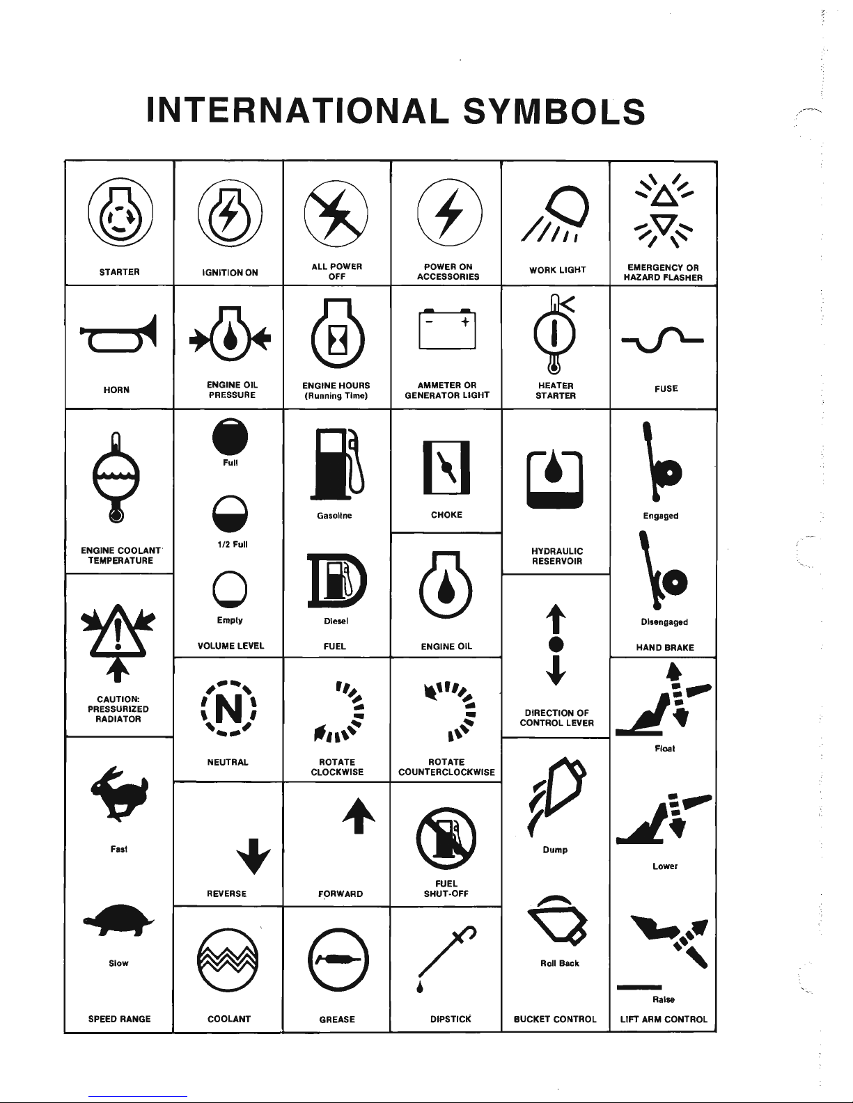
INTERNATIONAL
SYMBOLS
@ @
®
(£)
Q
'6/
......
,.
'/v~
///11
I \
STARTER
IGNITION ON
ALL POWER
POWER ON
WORK LIGHT
EMERGENCY
OR
OFF
ACCESSORIES
HAZARD FLASHER
~
~
®
0
c15
-v'-
HORN
ENGINE OIL
ENGINE HOURS
AMMETER
OR
HEATER
FUSE
PRESSURE
(Running Time) GENERATOR LIGHT STARTER
A
•
~~
IS]
c::J
~
Full
y
~
Gasoline
CHOKE
Engaged
ENGINE COOLANT'
1/2
Full
HYDRAULIC
\0
TEMPERATURE
JI)
(j)
RESERVOIR
*
0
t
Empiv
Diesel
Disengaged
VOLUME LEVEL
FUEL ENGINE OIL
•
HAND BRAKE
,--,
~
•
r"
,,-U/#.
~r-
CAUTION:
'N'
~
~
PRESSURIZED
..
, ,
-
-
DIRECTION OF
RADIATOR
'--'
4Itt
~
CONTROL LEVER
"n\'
.\~
Floal
NEUTRAL ROTATE ROTATE
C
if'
CLOCKWISE COUNTERCLOCKWISE
+
@
~:.~
r
•
Faal
+
Dump
Lower
FUEL
REVERSE
FORWARD
SHUT-OFF
~
....,
8
/'
'-.-
~~,
e
Slow
,
Roll Back
•
Raise
SPEED RANGE COOLANT
GREASE
DIPSTICK BUCKET CONTROL
LIFT ARM CONTROL
Page 3
Chapter
1
2
3
4
5
6
7
8
9
10
11
12
13
TABLE OF
CONTENTS
Description
International Symbols
Introduction.
.
Specifications .
Check Lists . .
Safety
.....
.
Controls & Safety Equipment
Operation
..
Adjustments
.......
.
Lubrication . . . . . . . . .
Attachments
& Accessories
Troubleshooting
Service
.......
.
Decal
Locations.
. . .
Maintenance Schedule
Index
........
.
Standard Hardware Torque
Warranty
........
.
IDENTIFICATION
INFORMATION
Page
Inside Front Cover
.2
.4
.7
10
18
29
39
43
46
49
57
73
78
82
86
Inside
Back
Cover
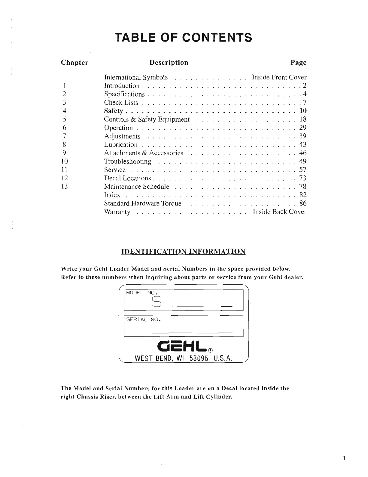
Write your Gehl Loader Model and Serial Numbers in the space provided below.
Refer to these numbers when inquiring about parts or
service
from your Gehl dealer.
jMOOEL
N5
L
jSERIAL
N_O_o
________________
__
CicHL®
WEST
BEND,
WI
53095
U.S.A.
The Model and Serial Numbers for this Loader are on a Decal located inside the
right Chassis Riser, between the
Lift
Arm and
Lift
Cylinder.
1
Page 4

HAPTER
1
INTRODUCTION
The information in this Operator's Manual was written to give the owner/operator assistance in preparing, adjusting,
maintaining and servicing
of
the Loader. More importantly, this manual provides an operating plan for safe and proper
use
of
the machine. Major points
of
safe operation are detailed in the
SAFETY
chapter
of
this manual. A chart
of
standard
hardware torques
is
located in the back
of
this manual.
The
GEHL
Company
asks
that
you
read
and
understand
the
contents
of
this
manual
COMPLETELY
and
become
familiar
with
your
new
machine,
BEFORE
attempting
to
operate
it.
Throughout this manual, information
is
provided which is set in italic type and introduced by the word
NOTE.
Be sure
to read carefully and comply with the message or directive given. Following this information will improve your operating
or maintenance efficiency, help you to avoid breakdowns or damage and extend your machine's life.
A plastic container
is
provided on the unit for storing the Operator's Manual. After using the Manual, please return it to
the container and keep it with the unit at all times!
If
this machine
is
resold, GEHL Company recommends that this
Manual be given
to
the new owner.
"Right" and "left" are determined from a position sitting on the Seat and facing forward. From this position:
If
your
Loader is T-Bar Controlled: the Propulsion (Traction) Control T-Bar is on the "left" and the Liftffilt Control
T-Bar
is
on the "right".
If
your
Loader is Hand/Foot Controlled: The "left" T-Bar controls the Propulsion (Traction) on the left side
of
the
machine. The
"right"
T-
Bar controls Propulsion (Traction) on the right side
of
the machine. The "leji" Foot Pedal controls
the Lift. The
"right" Foot Pedal controls the Tilt.
Our wide Dealership network stands by to provide you with any assistance you may require, including genuine
GEHL
service parts. All parts should be obtained from or ordered through your GEHL Dealer. Give complete information about
the
PaIt and include the model and serial numbers
of
your machine. Record the serial number in the space provided on
the previous page, as a handy record for quick reference.
GEHL Company reserves the right to make changes or improvements in the design or construction
of
any part without
incurring the obligation to install such changes on any unit previously delivered.
2
The GEHL Company,
in
cooperation
with
the
American
Society
of
Agricultural
Engineers and
the
Society
of
Automotive
Engineers,
has
adopted
this
SAFETY ALERT SYMBOL
to
pinpoint
characteristics
which,
if
NOT
properly
followed,
can create a
safety
hazard. When
you
see
this
symbol
in
this
manual
or
on
the
machine
itself,
you
are reminded
to
BE ALERT! Your
personal
safety
is
involved!
Page 5
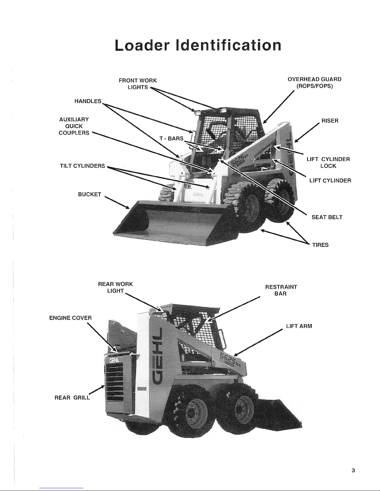
Loader
Identification
AUXILIARY
QUICK
COUPLERS
FRONT WORK
LIGHTS
TILT CYLINDERS
BUCKET
REAR GRILL
REAR WORK
LIGHT
RESTRAINT
BAR
LIFT CYLINDER
LOCK
LIFT CYLINDER
SEAT BELT
TIRES
LIFT ARM
3
Page 6
CHAPTER
2
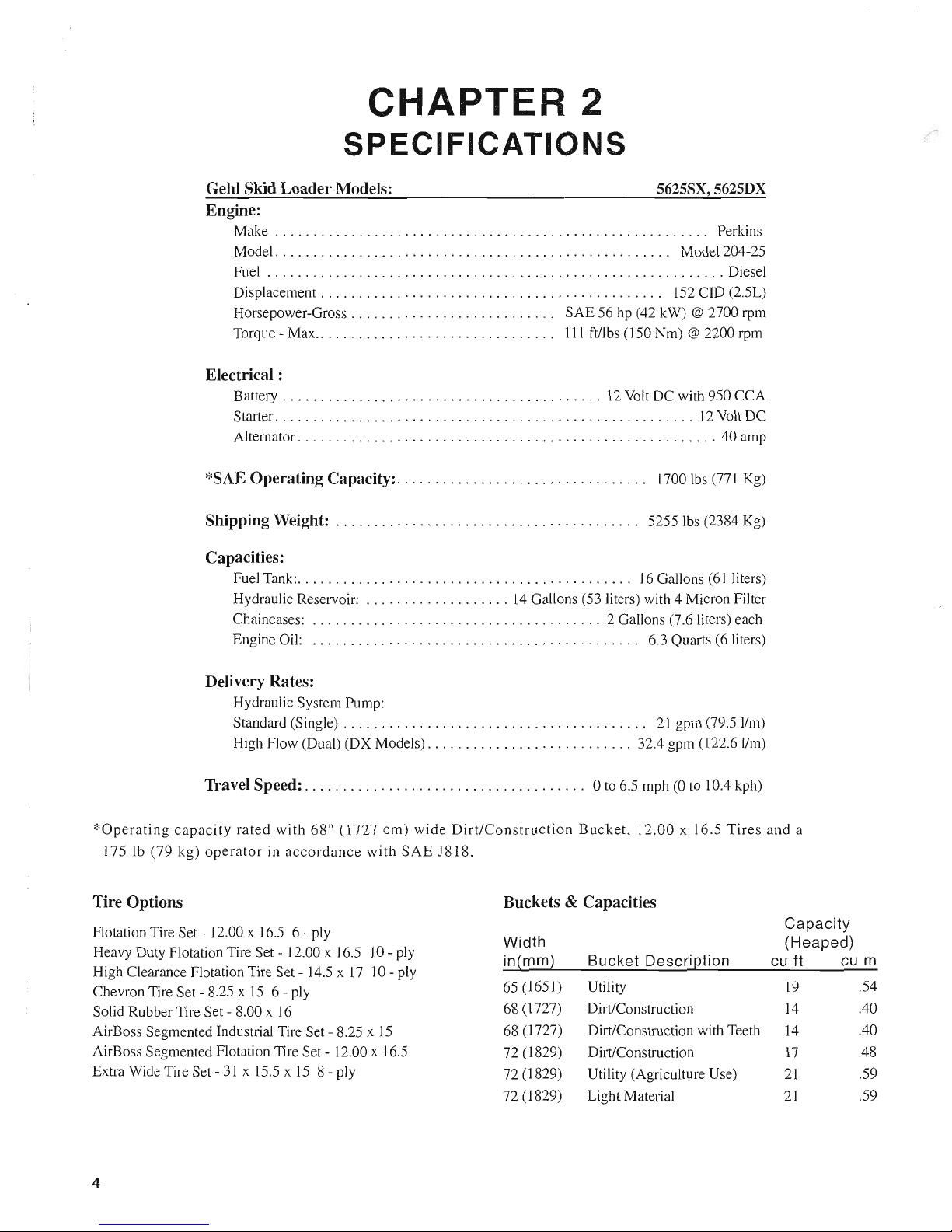
SPECIFICATIONS
Gehl Skid Loader Models:
Engine:
5625SX,5625DX
Make . . . . . . . . . . . . . . . . . . . . . . . . . . . . . . . . . . . . . . . . . . . . . . . . . . . . . . .
..
Perkins
Model
...................................................
, Model 204-25
Fuel
............................................................
Diesel
Displacement. . . . . . . . . . . . . . . . . . . . . . . . . . . . . . . . . . . . . . . . . . .
..
152
cm (2.5L)
Horsepower-Gross
...........................
SAE 56 hp (42 kW) @ 2700 rpm
Torque - Max.. . . . . . . . . . . . . . . . . . . . . . . . . . . . .
..
111
ftllbs (150 Nm) @ 2200 rpm
Electrical :
Battery
..........................................
12
Volt
DC with 950 CCA
Starter. . . . . . . . . . . . . . . . . . . . . . . . . . . . . . . . . . . . . . . . . . . . . . . . . . . . . . .
12
Volt
DC
Alternator
.......................................................
40 amp
*SAE Operating Capacity:. . . . . . . . . . . . . . . . . . . . . . . . . . . . . . .
..
1700
Ibs
(77 I Kg)
Shipping Weight:
..
. . . . . . . . . . . . . . . . . . . . . . . . . . . . . . . . . . . .
..
5255
Ibs
(2384 Kg)
Capacities:
Fuel Tank:
............................................
16
Gallons
(61
liters)
Hydraulic Reservoir:
...................
14
Gallons (53 liters) with 4 Micron Filter
Chaincases:
......................................
2 Gallons (7.6 liters) each
Engine Oil:
...........................................
6.3 Quarts (6 liters)
Delivery Rates:
Hydraulic System Pump:
Standard (Single) . . . . . . . . . . . . . . . . . . . . . . . . . . . . . . . . . . . . . .
..
2 I gpm (79.5 IIm)
High Flow (Dual) (DX Models)
...........................
32.4 gpm (122.6
11m)
Travel Speed: . . . . . . . . . . . . . . . . . . . . . . . . . . . . . . . . . . .
..
0 to 6.5 mph (0 to 10.4 kph)
*Operating
capacity
rated
with
68"
(1727
cm)
wide
Dirt/Construction
Bucket,
12.00
x 16.5
Tires
and
a
175 Ib (79 kg)
operator
in
accordance
with
SAE
J818.
Tire Options
Buckets & Capacities
Flotation Tire Set - 12.00 x 16.5 6 - ply
Capacity
Width
(Heaped)
Heavy Duty Flotation Tire Set - 12.00 x 16.5
10
- ply
High Clearance Flotation Tire Set - 14.5 x
17
10
- ply
Chevron Tire Set - 8.25 x
15
6 - ply
in(mm}
Bucket
Descri[2tion cu ft cu m
Solid Rubber Tire Set - 8.00 x
16
AirBoss Segmented Industrial Tire Set - 8.25 x
15
AirBoss Segmented Flotation Tire Set - 12.00 x 16.5
Extra Wide Tire Set -
31
x 15.5
xiS
8 - ply
4
65 (1651)
68 (1727)
68 (1727)
72 (1829)
72 (1829)
72 (1829)
Utility
Dirt/Construction
Dirt/Construction with Teeth
Dirt/Construction
Utility (Agriculture Use)
Light Material
19
.54
14
.40
14
.40
17
.48
21
.59
21
.59
Page 7

Standard
Features
e Side-Mount "Load Trak" T-Bar Controls
e Power-Assist Controlled Hydrostatic Drive
e ROPS-FOPS ISO Level 2 Approved Overhead Guard
e Self-Level Lift Action
.. Independent Hydraulic Reservoir
.. Operator Restraint Bar with Armrests
e Seat and Operator Restraint Bar Interlock for Starter,
Lift Cylinders, and Tilt Cylinders
e Adjustable Contoured Seat with Seat Belt
.. Mechanical Lift Cylinder Lock
.. Integral Belly Plate with Cleanout
• Hourmeter
.. Coolant Temperature Gauge
.. Fuel Gauge
• Oil Pressure, Battery Charge Indicators
..
Hand and Foot Throttle-Hand Controls
III Glow Plug Statting Assist
III Disc Type Handbrake
e Operational Lights - 2 Front, I Rear
III Spark Arrestor Muffler
• Locking Fuel Cap
• Dual Element Air Cleaner
III Front Auxiliary Hydraulics with 3/4" Couplers
• Gehl Quick-Lock Attachment Mounting
III Sound Deadening Package
• 50/50 Anti-Freeze Protection
Accessories
•
3"
Seat Belt -Where required by Law
III Centrifugal Pre-Cleaner
III All Weather Rigid Cab Enclosure with Door Kit
III Vinyl Cab Enclosure Kit
..
Wiper Kit
..
HeaterlDefroster Kit
..
Back-Up Alarm
III Dual Flasher Kit
..
Strobe Light
..
Horn Kit
..
Lift Kit
..
Hydraulic Reservoir Heater
..
Enclosed Alternator -
12
Volt,
30 Amp
• Suspension Seat
• Engine Heater - Block -400 Watt
..
Engine Auto-Shutdown System Kit
• Battery Disconnect Switch
5
Page 8
A
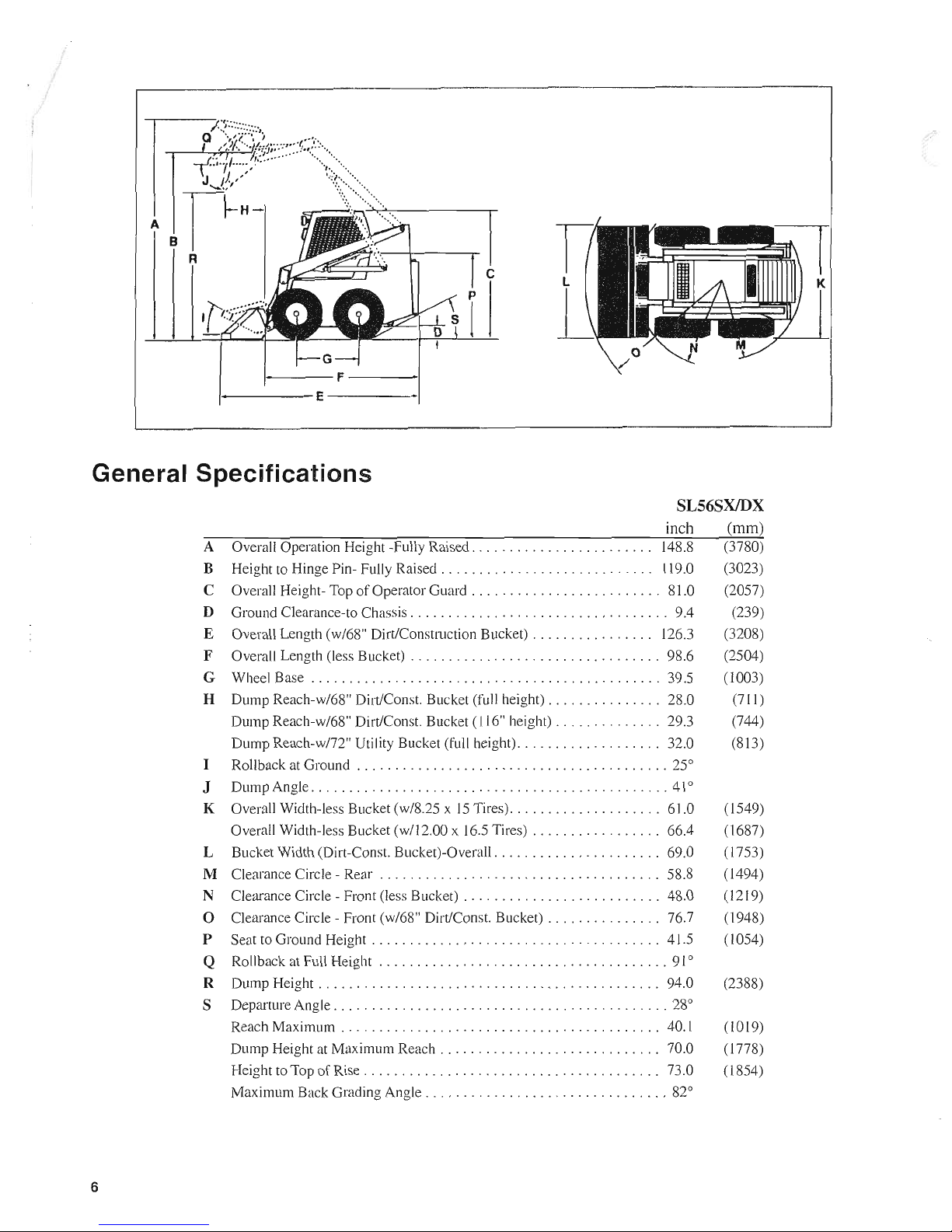
General Specifications
SL56SX/DX
6
inch
A Overall Operation Height -Fully Raised
........................
14S.S
B Height to Hinge Pin- Fully
Raised.
. . . . . . . . . . . . . . . . . . . . . . . . .
..
119.0
C Overall Height-Top
of
Operator
Guard.
. . . . . . . . . . . . . . . . . . . . . .
..
SI.O
D Ground Clearance-to Chassis
..................................
9.4
E Overall Length (w/6S" DirtlConstruction Bucket)
................
126.3
F Overall Length (less Bucket)
.................................
9S.6
G Wheel Base
..............................................
39.5
H Dump Reach-w/6S" Dirt/Const. Bucket (full height)
...............
2S.0
Dump Reach-w/6S" Dirt/Const. Bucket (116" height)
..............
29.3
Dump
Reach-w/72" Utility Bucket (full height)
...................
32.0
I Rollback at Ground
.........................................
25°
J Dump Angle
...............................................
41°
K Overall Width-less Bucket
(w/S.25
x
15
Tires)
....................
61.0
Overall Width-less Bucket (wI12.00 x 16.5 Tires)
.................
66.4
L Bucket Width (Dirt-Const. Bucket)-Overall
......................
69.0
M Clearance Circle - Rear . . . . . . . . . . . . . . . . . . . . . . . . . . . . . . . . . . .
..
5S.S
N Clearance Circle - Front (less Bucket) . . . . . . . . . . . . . . . . . . . . . . . . . . 4S.0
o Clearance Circle - Front (w/6S" Dirt/Const. Bucket)
...............
76.7
P Seat to Ground Height . . . . . . . . . . . . . . . . . . . . . . . . . . . . . . . . . . . . . . 41.5
Q Rollback at Full Height
......................................
91
°
R Dump
Height.
. . . . . . . . . . . . . . . . . . . . . . . . . . . . . . . . . . . . . . . . . .
..
94.0
S Departure Angle
............................................
2So
Reach Maximum . . . . . . . . . . . . . . . . . . . . . . . . . . . . . . . . . . . . . . . . . . 40.1
Dump Height at Maximum
Reach.
. . . . . . . . . . . . . . . . . . . . . . . . . .
..
70.0
Height to Top
of
Rise
.......................................
73.0
Maximum Back Grading Angle
................................
S2°
(mm)
(37S0)
(3023)
(2057)
(239)
(320S)
(2504)
(1003)
(711)
(744)
(SI3)
(1549)
(16S7)
(1753)
(1494)
(1219)
( 1945)
(1054)
(23SS)
(1019)
(l77S)
(lS54)
Page 9
c
o
:;::::;
~
o
't:
Q)
a.
-
ctS
~
o
()
~
ii:
~C/)
...
Q)
C6
Q)
c
Q)
>
o
E
Q)
a:
CHAPTER
3
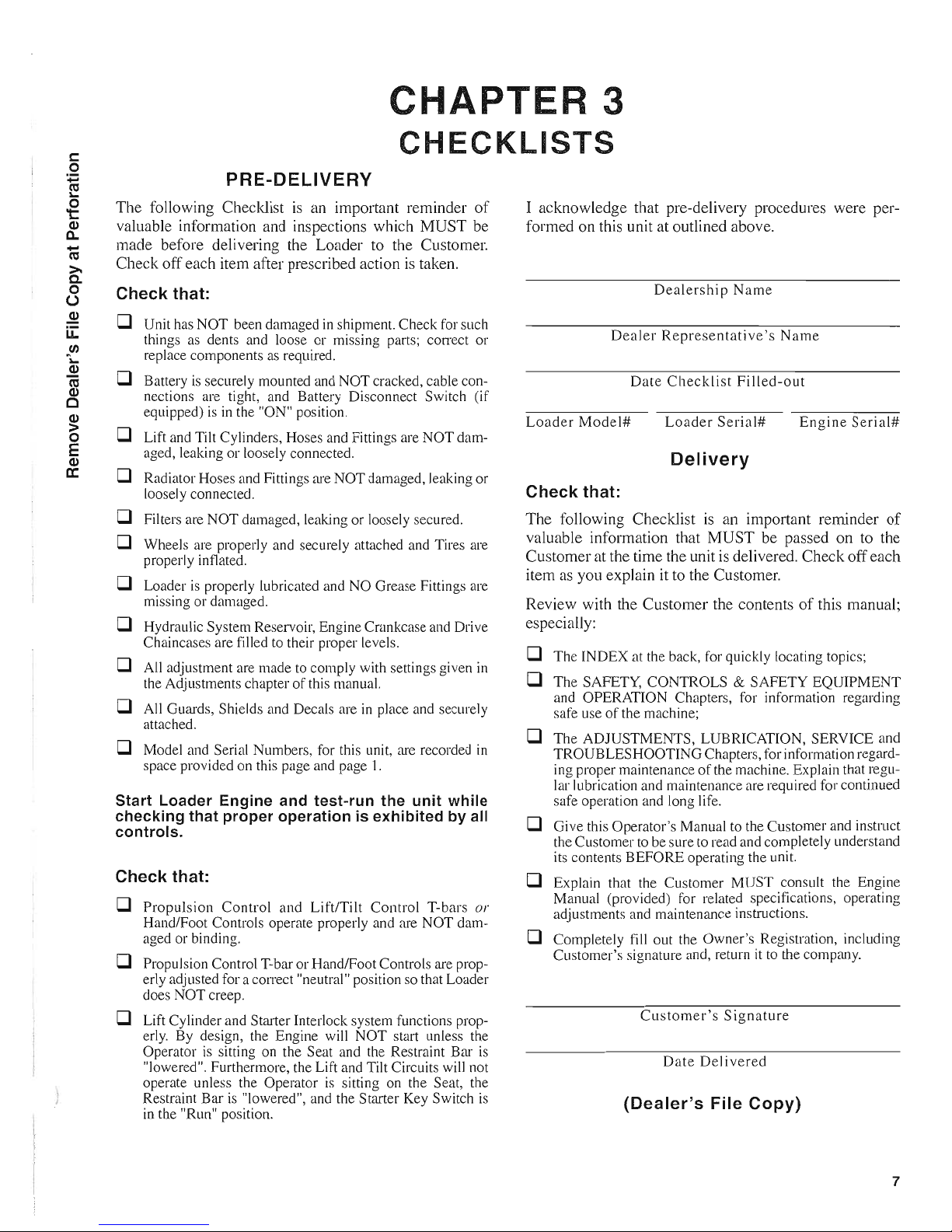
CHECKLISTS
PRE-DELIVERY
The following Checklist
is
an important reminder
of
valuable information and inspections which MUST be
made before delivering the Loader
to
the Customer.
Check off each item after prescribed action
is
taken.
Check that:
D Unit has NOT been damaged
in
shipment. Check for such
things
as
dents and loose or missing parts; con-ect or
replace components
as
required .
D Battery is securely mounted and
NOT
cracked, cable con-
nections are tight, and Battery Disconnect Switch (if
equipped)
is
in
the "ON" position.
D Lift and Tilt Cylinders, Hoses and Fittings are
NOT
dam-
aged, leaking or loosely connected.
D Radiator Hoses and Fittings are
NOT
damaged, leaking or
loosely connected.
D Filters are NOT damaged, leaking or loosely secured.
D Wheels are properly and securely attached and Tires are
properly inflated.
D Loader
is
properly lubricated and NO Grease Fittings are
missing or damaged.
D Hydraulic System Reservoir, Engine Crankcase and Drive
Chaincases are filled to their proper levels.
D All adjustment are made
to
comply with settings given
in
the Adjustments chapter
of
this manual.
D All Guards, Shields and Decals are in place and securely
attached.
D Model and Serial Numbers, for this unit,
m'e
recorded in
space provided on this page and page
I.
Start Loader Engine and test-run the unit while
checking that proper operation is exhibited by all
controls.
Check that:
D
Propulsion
Control
and Lift/Tilt Control T-bars
or
Hand/Foot Controls operate properly and are NOT damaged or binding.
D Propulsion Control T-bar or HandlFoot Controls are prop-
erly adjusted for a correct "neutral" position so that Loader
does NOT creep.
D Lift Cylinder and Starter Interlock system functions prop-
erly. By design, the Engine will NOT start unless the
Operator is sitting on the Seat and the Restraint Bar
is
"lowered". Furthermore, the Lift and Tilt Circuits will not
operate unless the Operator is sitting on the Seat, the
Restraint Bar is "lowered", and the Starter Key Switch is
in the "Run" position.
I acknowledge that pre-delivery procedures were performed on this unit at outlined above.
Dealership
Name
Dealer
Representative's
Name
Date
Checklist
Filled-out
Loader
Model#
Loader
Serial#
Engine
Serial#
Delivery
Check that:
The following Checklist is an important reminder
of
valuable information that MUST be passed on to the
Customer at the time the unit
is
delivered. Check off each
item as you explain it to the Customer.
Review with the Customer the contents
of
this manual;
especially:
D The INDEX at the back, for quickly locating topics;
D The SAFETY, CONTROLS & SAFETY EQUIPMENT
and OPERATION Chapters, for information regarding
safe use
of
the machine;
D The ADJUSTMENTS, LUBRICATION, SERVICE and
TROUBLESHOOTING Chapters, for information regarding proper maintenance
of
the machine. Explain that regular lubrication and maintenance are required for continued
safe operation and long life.
D Give this Operator's Manual to the Customer and instruct
the Customer to be sure to read and completely understand
its contents BEFORE operating the unit.
D Explain that the Customer
MUST
consult the Engine
Manual (provided) for related specifications, operating
adjustments and maintenance instructions.
D Completely fill out the Owner's Registration, including
Customer's signature and, return it to the company.
Customer's
Signature
Date
Delivered
(Dealer's
File
Copy)
7
Page 10

INTENTIONALLY
BLANK
(To
be
removed
as
Dealer's
file
copy)
8
Page 11
CHAPTER
3
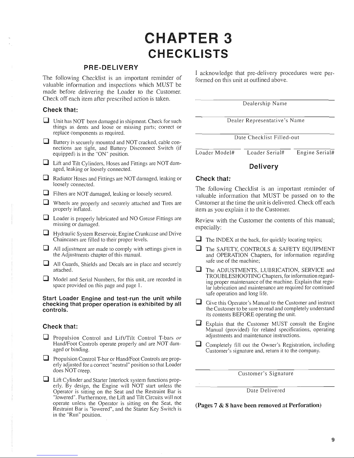
CHECKLISTS
PRE-DELIVERY
The following Checklist
is
an important reminder
of
valuable information and inspections which MUST be
made before delivering the Loader
to
the Customer.
Check off each item after prescribed action
is
taken.
Check that:
D Unit has NOT been damaged
in
shipment. Check for such
things as dents and loose or missing parts;
COlTect
or
replace components
as
required.
D Battery
is
securely mounted and NOT cracked, cable con-
nections are tight, and Battery Disconnect Switch (if
equipped) is
in
the "ON" position.
D Lift and Tilt Cylinders, Hoses and Fittings are NOT dam-
aged, leaking or loosely connected.
D Radiator Hoses and Fittings are NOT damaged, leaking or
loosely connected.
D Filters are NOT damaged, leaking or loosely secured.
D Wheels are properly and securely attached and Tires are
properly inflated.
D Loader is properly lubricated and NO Grease Fittings are
missing or damaged.
D Hydraulic System Reservoir, Engine Crankcase and Drive
Chain cases are filled to their proper levels.
D All adjustment are made to comply with settings given
in
the Adjustments chapter
of
this manual.
D All Guards, Shields and Decals are
in
place and securely
attached.
D Model and Serial Numbers, for this unit, are recorded
in
space provided on this page and page
1.
Start Loader Engine and test-run the unit while
checking that proper operation is exhibited by all
controls.
Check that:
D
Propulsion
Control and Lift/Tilt Control T-bars or
HandlFoot Controls operate properly and are NOT damaged or binding.
D Propulsion Control T-bar or Hand/Foot Controls are prop-
erly adjusted for a correct "neutral" position so that Loader
does NOT creep.
D Lift Cylinder and Starter Interlock system functions prop-
erly. By design, the Engine will NOT start unless the
Operator is sitting on the Seat and the Restraint Bar
is
"lowered". FUlthermore, the Lift and Tilt Circuits will not
operate unless the Operator
is
sitting on the Seat, the
Restraint Bar is "lowered", and the Starter Key Switch is
in the "Run" position.
I acknowledge that pre-delivery procedures were performed on this unit at outlined above.
Dealership
Name
Dealer
Representative's
Name
Date
Checklist
Filled-out
Loader
Model#
Loader
Serial#
Engine
Serial#
Delivery
Check that:
The following Checklist is an important reminder
of
valuable information that MUST be passed on to the
Customer at the time the unit
is
delivered. Check off each
item as you explain it
to
the Customer.
Review with the Customer the contents
of
this manual;
especially:
D The INDEX at the back, for quickly locating topics;
D The SAFETY, CONTROLS & SAFETY EQUIPMENT
and OPERATION Chapters, for information regarding
safe use
of
the machine;
D The ADJUSTMENTS, LUBRICATION, SERVICE and
TROUBLESHOOTING Chapters, forinfonnation regarding proper maintenance
of
the machine. Explain that regular lubrication and maintenance are required for continued
safe operation and long life.
D Give this Operator's Manual to the Customer and instruct
the Customer to be sure to read and completely understand
its contents BEFORE operating the unit.
D Explain that the Customer MUST consult the Engine
Manual (provided) for related specifications, operating
adjustments and maintenance instructions.
D Completely fill out the Owner's Registration, including
Customer's signature and, return
it
to the company.
Customer's
Signature
Date
Delivered
(Pages 7 & 8 have been removed at Perforation)
9
Page 12
CHAPTER
4
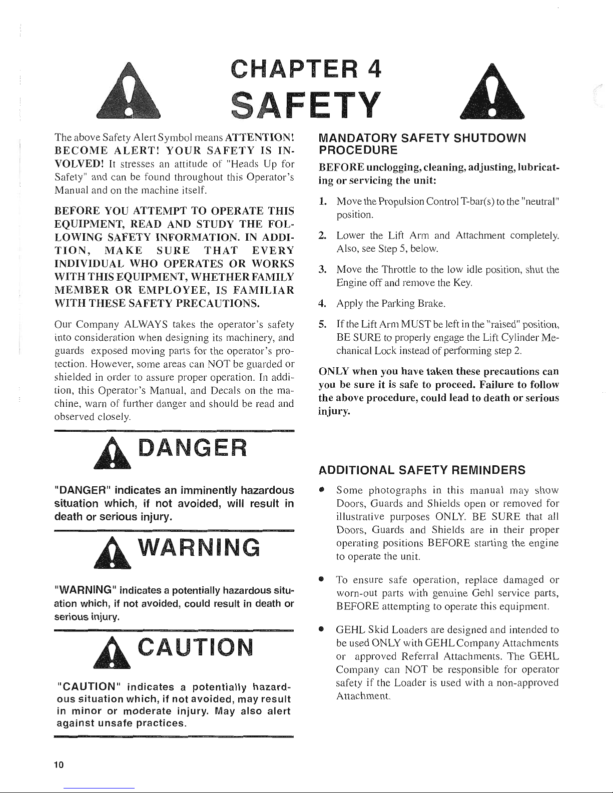
The above Safety Alert Symbol means
ATTENTION!
BECOME
ALERT!
YOUR
SAFETY
IS
IN-
VOLVED! It stresses an attitude
of
"Heads Up for
Safety" and can be found throughout this Operator's
Manual and on the machine itself.
BEFORE
YOU
ATTEMPT
TO
OPERATE
THIS
EQUIPMENT,
READ
AND
STUDY
THE
FOL-
LOWING
SAFETY
INFORMATION.
IN
ADDI-
TION,
MAKE
SURE
THAT
EVERY
INDIVIDUAL
WHO
OPERATES
OR
WORKS
WITH
THIS
EQUIPMENT,
WHETHER
FAMILY
MEMBER
OR
EMPLOYEE,
IS
FAMILIAR
WITH
THESE
SAFETY
PRECAUTIONS.
Our Company ALWAYS takes the operator's safety
into consideration when designing its machinery, and
guards exposed moving parts for the operator's protection. However, some areas can NOT be guarded or
shielded in order to assure proper operation. In addition, this Operator's Manual, and Decals on the machine, warn
of
further danger and should be read and
observed closely.
DAN
ER
"DANGER" indicates
an
imminently hazardous
situation which,
if
not avoided, will result
in
death or serious injury.
WARNING
"WARNING" indicates a potentially hazardous situ-
ation which,
if
not avoided, could result
in
death
or
serious injury.
CAUTI
N
"CAUTION"
indicates a potentially
hazardous situation which, if not avoided, may result
in
minor
or
moderate
injury. May also
alert
against unsafe practices.
10
MANDATORY SAFETY SHUTDOWN
PROCEDURE
BEFORE
unclogging, cleaning, adjusting, lubricat-
ing or servicing the unit:
1. Move the Propulsion Control T-bar(s)
to
the "neutral"
position.
2. Lower the Lift Arm and Attachment completely.
Also, see Step 5, below.
3. Move the Throttle
to
the low idle position, shut the
Engine off and remove the
Key.
4. Apply the Parking Brake.
S.
If
the Lift Arm MUST be left
in
the "raised" position,
BE SURE
to
properly engage the Lift Cylinder Me-
chanical Lock instead
of
performing step
2.
ONLY when you have taken these precautions can
you be sure it is safe to proceed. Failure to follow
the above procedure, could lead to death or serious
injury.
ADDITIONAL SAFETY REMINDERS
e
Some
photographs
in this manual may
show
Doors, Guards and Shields open or removed for
illustrative purposes
ONLY.
BE SURE that all
Doors, Guards and Shields are in their proper
operating positions BEFORE starting the engine
to operate the unit.
e To ensure safe operation, replace damaged
or
worn-out parts with genuine Gehl service parts,
BEFORE attempting to operate this equipment.
e GEHL Skid Loaders are designed and intended to
be used ONLY with GEHL Company Attachments
or
approved Referral Attachments. The GEHL
Company can NOT be responsible for operator
safety
if
the Loader is used with a non-approved
Attachment.
Page 13
SA
ETV
(CONTINUED)
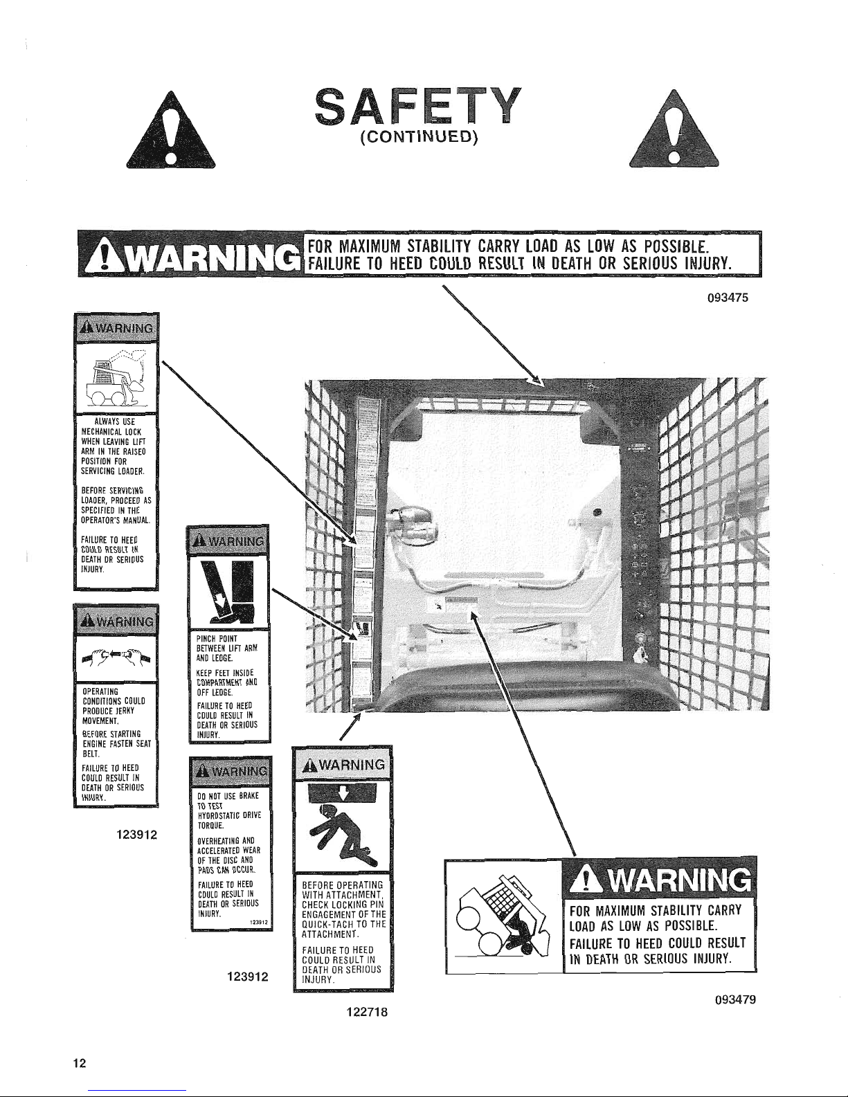
• The stability
of
a Skid Loader is determined by its
short wheel base. The following elements: the
terrain,
Engine
speed,
load
being
carried
or
dumped, and/or abrupt Control movements, can
affect stability.
IF
MISUSED, ANY
OF
THE
ABOVE
FACTORS
CAN
CAUSE
THE
LOADER TO TIP, THROWING YOU FORWARD
OR
OUT
OF
THE
UNIT, CAUSING
DEATH
OR
SERIOUS INJURY. Therefore,
ALWAYS have the Operator Restraint Bar
"low-
ered"
and wear the Seat Belt. Operate the Controls
smoothly and gradually at an appropriate Engine
speed which matches the operating conditions.
• For additional stability when operating on inclines
or ramps, ALWAYS travel with the heavier end
of
the Loader to the top
of
the incline.
• NEVER attempt to by-pass the Keyswitch to start
the Loader Engine. Only use the jump-starting
procedure detailed in the service chapter
of
this
manual.
• Do NOT attempt to remove the Radiator Cap after
the Engine has reached operating temperature or
has overheated because the Engine Coolant will be
extremely
HOT
and under pressure. ALWAYS
wait for the Engine to cool down BEFORE attempting to relieve pressure and remove the Radiator Cap. Failure to heed could result in severe
burns.
• NEVER use your hands to search for hydraulic
fluid leaks, use a piece
of
paper or cardboard.
Escaping fluid under pressure can be invisible and
can penetrate the skin and cause a serious injury.
If
any fluid is injected into your skin, see a doctor
at once. Injected fluid MUST be surgically removed by a doctor or gangrene may result.
•
ALWAYS
wear safety glasses with side shields
when striking metal against metal. In addition, it
is also recommended that a softer (non-chipable
material) be used to cushion the blow. Failure
to
heed could lead to serious injury to the eyes or
other parts
of
the body.
• DO NOT raise or drop a loaded Bucket or Fork
suddenly. Abrupt movements under load can cause
serious instability.
•
DO
NOT push the Lift Control all the way forward
(into the
"float"
position) with the Attachment
loaded and the Lift Arm raised as this will cause
the Lift Arm to drop, very rapidly.
• DO NOT drive too close to an excavation
or
ditch;
BE SURE that the surrounding ground has ade-
quate strength to support the weight
of
the Loader
and the load.
• DO NOT smoke or have any spark producing
equipment in the area while filling the Fuel Tank
or
while working on the fuel
or
hydraulic systems.
11
Page 14
ALWAYS
USE
MECHANICAL
LOCK
WHEN
LEAVING
LIFT
ARM
IN
THE
RAISED
POSITION
FOR
SERVICING
LOAOER.
BEFORE
SERVICING
LOADER,
PROCEED
AS
SPECIFIED
IN
THE
OPERATOR'S
MANUAl.
FAILURE
TO
HEED
COULD
RESULT
IN
DEATH
OR
SERIOUS
INJURY.
OPERATING
CONDITIONS
COULD
PRODUCE
JERKY
MOVEMENT.
BEFORE
STARTING
ENGINE
FASTEN
SEAT
BELT.
FAILURE
TO
HEED
COULD
RESULT
IN
DEATH
OR
SERIOUS
INJURY.
123912
12
KEEP
FEET
INSIDE
COMPARTMENT
AND
OFF
LEDGE.
FAILURE
TO
HEED
COULO
RESULT
IN
DEATH
OR
SERIOUS
INJURY.
DO
NOT
USE
BRAKE
TO
TEST
HYDROSTATIC
DRIVE
TORQUE.
OVERHEATING
AND
ACCELERATED
WEAR
OF
THE
DISC
AND
PADS
CAN
OCCUR.
FAILURE
TO
HEED
COULD
RESULT
IN
DEATH
OR
SERIOUS
INJURY.
123912
123912
(CONTINUED)
OR
MAXIMUM
STABILITY
CARRY
LOAD
AS
LOW
AS
POSSIBLE.
AlLURE
TO
HEED
COULD
RESULT
IN
DEATH
OR
SERIOUS
INJURY.
BEFORE
OPERATING
WITH
ATTACHMENT,
CHECK
LOCKING
PIN
ENGAGEMENT
OF
THE
QUICK-TACH
TO
THE
ATTACHMENT.
FAILURE
TO
HEED
COULD
RESULT
IN
DEATH
OR
SERIOUS
INJURY.
122718
093475
FOR
MAXIMUM
STABILITY
CARRY
LOAD
AS
LOW
AS
POSSIBLE.
FAILURE
TO
HEED
COULD
RESULT
IN
DEATH
OR
SERIOUS
INJURY.
093479
Page 15

DO
NOT
BYPASS
ENGINE
KEYSWITCH
BY
CONNECTING
AT
THE
STARTER
TERMINALS
TO
JUMP
START.
FOLLOW
RECOMMENDED
PROCEDURE
IN
THE
OPERATOR'S
MANUAL
FOR
JUMP
STARTING
USING
THE
ENGINE
KEYSWITCH.
STARTING
IN
GEAR
COULD
OCCUR
IF
THE
STARTING
CONTROL
CIRCUIT
IS
BYPASSED.
FAILURE
TO
HEED
COULD
RESULT
IN
DEATH
OR
SERIOUS
INJURY.
091033
IMPROPERLY
GROUNDED
HEATING
UNIT
CAN
CAUSE
ELECTRIC
SHOCK
OR
ElECTROCUTION.
MAKE
SURE
LOADER
IS
GROUNDED
WHEN
USING
ELECTRIC
HEATER.
FAILURE
TO
HEED
WILL
RESULT
IN
DEATH
OR
SERIOUS
INJURY.
093484
(CONTINUED)
ROTATING
COMPONENTS
CAN
CUT
HANDS.
FAILURE
TO
HEED
WILL
RESULT
IN
DEATH
OR
SERIOUS
INJURY.
091050
091050
PRESSURE
CAP
072798
13
Page 16
14
SAFETY
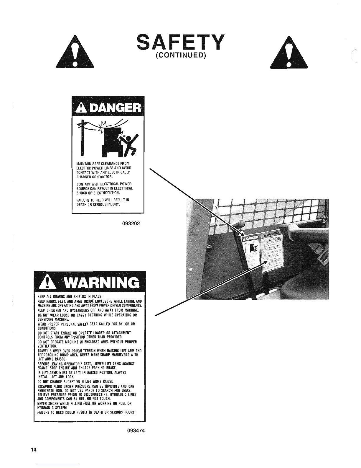
MAINTAIN
SAFE
CLEARANCE
FROM
ELECTRIC
POWER
LINES
AND
AVOID
CONTACT
WITH
ANY
ELECTRICALLY
CHARGED
CONDUCTOR.
CONTACT
WITH
ELECTRICAL
POWER
SOURCE
CAN
RESULT
IN
ELECTRICAL
SHOCK
OR
ELECTROCUTION.
FAILURE
TO
HEED
WILL
RESULT
IN
DEATH
OR
SERIOUS
INJURY.
093202
KEEP
ALL
GUARDS
AND
SHIELDS
IN
PLACE.
KEEP
HANDS,
FEET,
AND
ARMS
INSIDE
ENCLOSURE
WHilE
ENGINE
AND
MACHINE
ARE
OPERATING
AND
AWAY
FROM
POWER
DRIVEN
COMPONENTS.
KEEP
CHILDREN
AND
BYSTANDERS
OFF
AND
AWAY
FROM
MACHINE.
DO
NOT
WEAR
LOOSE
OR
BAGGY
CLOTHING
WHILE
OPERATING
DR
SERVICING
MACHINE.
WEAR
PROPER
PERSONAL
SAFETY
GEAR
CALLED
FOR
BY
JOB
OR
CONDITIONS.
DO
NOT
START
ENGINE
OR
OPERATE
LOADER
OR
ATTACHMENT
CONTROLS
FROM
ANY
POSITION
OTHER
THAN
PROVIDED.
DO
NOT
OPERATE
MACHINE
IN
ENCLOSED
AREA
WITHOUT
PROPER
VENTILATION.
TRAVEL
SLOWLY
OVER
ROUGH
TERRAIN
WHEN
RAISING
LIFT
ARM
AND
APPROACHING
DUMP
AREA.
NEVER
MAKE
SHARP
MANUEVERS
WITH
LIFT
ARMS
RAISED.
BEFORE
LEAVING
OPERATOR'S
SEAT,
LOWER
LIFT
ARMS
AGAINST
FRAME,
STOP
ENGINE
AND
ENGAGE
PARKING
BRAKE.
IF
LIFT
ARMS
MUST
BE
LEFT
IN
RAISED
POSTlON,
ALWAYS
INSTALL
LIFT
ARM
LOCK.
DO
NOT
CHANGE
BUCKET
WITH
LIFT
ARMS
RAISED.
ESCAPING
flUID
UNDER
PRESSURE
CAN
BE
INVISIBLE
AND
CAN
PENETRATE
SKIN.
DO
NOT
USE
HANDS
TO
SEARCH
FOR
LEAKS.
RELIEVE
PRESSURE
PRIOR
TO
DISCONNECTING.
HYDRAULIC
LINES
AND
COMPONENTS
CAN
BE
HOT.
DO
NOT
TOUCH.
NEVER
SMOKE
WHILE
FIlliNG
FUEL
OR
WORKING
ON
FUEl
OR
HYDRAULIC
SYSTEM.
FAILURE
TO
HEED
COULD
RESULT
IN
DEATH
OR
SERIOUS
INJURY.
093474
(CONTINUED)
Page 17
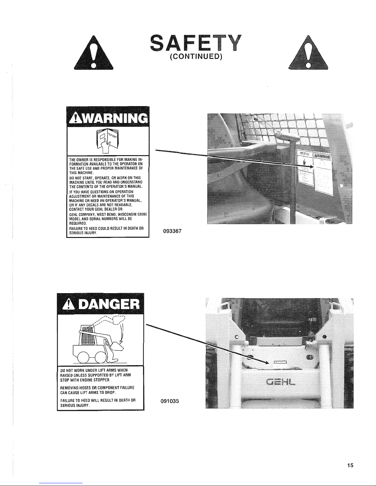
THE
OWNER
IS
RESPONSIBLE
FOR
MAKING
IN·
FORMATION
AVAILABLE
TO
THE
OPERATOR
ON
THE
SAFE
USE
AND
PROPER
MAINTENANCE
OF
THIS
MACHINE.
DO
NOT
START,
OPERATE,
OR
WORK
ON
THIS
MACHINE
UNTIL
YOU
READ
AND
UNDERSTAND
THE
CONTENTS
OF
THE
OPERATOR'S
MANUAl.
IF
YOU
HAVE
QUESTIONS
ON
OPERATION
ADJUSTMENT
OR
MAINTENANCE
OF
THIS
MACHINE
OR
NEED
AN
OPERATOR'S
MANUAL,
OR
IF
ANY
DECALS
ARE
NOT
READABLE,
CONTACT
YOUR
GEHL
DEALER
OR
GEHL
COMPANY,
WEST
BEND,
WISCONSIN
53095
MODEL
AND
SERIAL
NUMBERS
WILL
BE
REQUIRED.
FAILURE
TO
HEED
COULD
RESULT
IN
DEATH
OR
SERIOUS
INJURY.
DO
NOT
WORK
UNDER
LIFT
ARMS
WHEN
RAISED
UNLESS
SUPPORTED
BY
LIFT
ARM
STOP
WITH
ENGINE
STOPPED.
REMOVING
HOSES
OR
COMPONENT
FAILURE
CAN
CAUSE
LIFT
ARMS
TO
DROP.
FAILURE
TO
HEED
WILL
RESULT
IN
DEATH
OR
SERIOUS
INJURY.
(CONTINUED)
093367
091035
15
Page 18
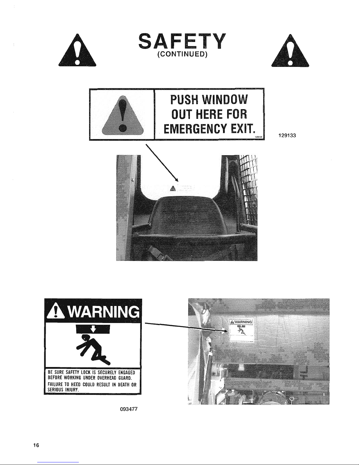
16
BE
SURE
SAFETY
LOCK
IS
SECURELY
ENGAGED
BEFORE
WORKING
UNDER
OVERHEAD
GUARD.
FAILURE
TO
HEED
COULD
RESULT
IN
DEATH
OR
SERIOUS
INJURY.
093477
F
(CONTINUED)
129133
Page 19
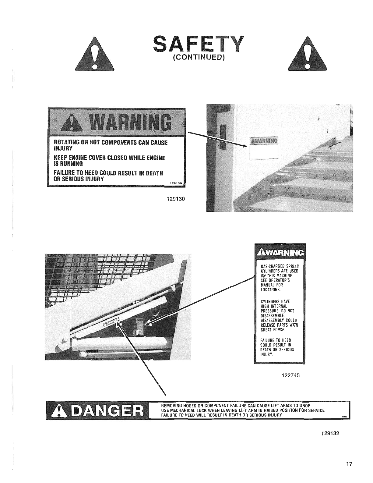
ROTATING
OR
HOT
COMPONENTS
CAN
CAUSE
INJURY
KEEP
ENGINE
COVER
CLOSED
WHilE
ENGINE
IS
RUNNING
fAILURE
TO
HEED
COULD
RESULT
IN
DEATH
OR
SERIOUS
iNJURY
(CONTINUED)
129130
129130
GAS-CHARGED
SPRING
CYLINDERS
ARE
USED
ON
THIS
MACHINE.
SEE
OPERATOR'S
MANUAL
FOR
LOCATIONS.
CYLINDERS
HAVE
HIGH
INTERNAL
PRESSURE.
DO
NOT
DISASSEMBLE.
DISASSEMBLY
COULD
RElEASE
PARTS
WITH
GREAT
FORCE.
FAILURE
TO
HEED
COULD
RESULT
IN
DEATH
OR
SERIOUS
INJURY.
122745
REMOVING
HOSES
OR
COMPONENT
FAILURE
CAN
CAUSE
LIFT
ARMS
TO
OROP
USE
MECHANICAL
LOCK
WHEN
LEAVING
LIFT
ARM
IN
RAISEO
POSITION
FOR
SERVICE
FAILURE
TO
HEED
WILL
RESULT
IN
DEATH
OR
SERIOUS
INJURY
129132
17
Page 20
CHAPTER
5
CONTROLS
&
SAFETY
EQUIPMENT
CAUTION
Become
familiar
with
and
know
how
to
use
ALL
safety
devices
and
controls
on
the
Skid
Loader
BEFORE
attempting
to
operate
it.
Know
how
to
stop
Loader
operation
BEFORE
starting
it.
This
GEHL
Skid
Loader
is
designed
and
intended
to
be
used
ONLY
with
a
GEHL
Company
Attachment
or a GEHL
Company
approved
accessory
or
referral
attachment.
The
GEHL
Company
can
NOT
be
responsible
for
operator
safety
if
the
Loader
is
used
with a non-approved
attachment.
GUARDS & SHIELDS
Whenever
possible and without affecting Loader
operation, Guards and Shields are used to protect
potentially hazardous areas. In many places, Decals
are also provided to warn
of
potential dangers and/or
to display special operating procedures.
WARNING
Read
and
thoroughly
understand
ALL
Safety
Decals
on
the
Loader
BEFORE
attempting
to
operate
it.
Do NOT
attempt
to
operate
the
Loader
unless
ALL
factory
installed
Guards
and
Shields
are
properly
secured
in
place.
18
CONTROLS
Your
Loader
could be
equipped
with
either
"Hand
&
Foot"
or
"T-Bar"
Controls.
Follow
instructions
appropriate
for
your
Loader
type.
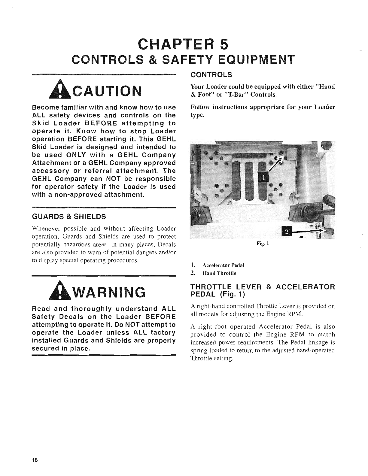
Fig. 1
1.
Accelerator Pedal
2.
Hand
Throttle
THROTTLE
LEVER
&
ACCELERATOR
PEDAL
(Fig.
1)
A right-hand controlled Throttle Lever is provided on
all models for adjusting the Engine RPM.
A
right-foot
operated
Accelerator
Pedal
is also
provided
to
control
the
Engine
RPM
to
match
increased power requirements. The Pedal linkage is
spring-loaded to return to the adjusted hand-operated
Throttle setting.
Page 21
T",BAR
CONTROLLED
LOADERS
(Fig.
2)
Side-mounted T
-Bars
are provided on Skid Loader
to
control the hydraulic and hydrostatic functions
of
the Loader.
Both T-Bars return to their "neutral" positions when released.
PROPULSION CONTROL
T-BAR
The left T-Bar
is
the Propulsion Control which is
linked to the Hydrostatic Drives.
Forward
Travel:
Push the left T-Bar straight forward
(without twisting).
Reverse
Travel:
Pull the left T-Bar straight backwards
(without twisting).
Turning
during
Travel:
Twist the left T-Bar and move
it slightly forward or rearward to cause a slow gradual
forward or rearward turn. The farther the T-Bar
is
moved, in any direction, the faster the maneuver will
be made. Engine RPM also has a directly proportional
affect on movement.
Fast
Turning
(Pivoting):
Twist
the
left
T-Bar
clockwise to cause a spin turn to the right; twist the
T-Bar counterclockwise
to
cause a spin turn to the left.
On a spin turn, the wheels opposite the direction
of
the
turn will rotate forward and the wheels on the same
side as the direction
of
the turn will rotate rearward.
CAUTI
N
ALWAYS
make
sure
that
both
T-Bars
are
in
their
"neutral"
positions
BEFORE
attempting
to
start
the
Engine.
Operation
of
the
T-Bar
controls
should
be
smooth
and
with
safety
in
mind.
Excessive
travel
speed
together
with
quick
T-Bar
movements,
with
NO
regard
for
conditions
and
circumstances,
is
hazardous
and
could
cause
an
accident.
Lift/Tilt
Control
T-Bar
The
right T-Bar controls the Lift (Arm) and Tilt
(Attachment) through linkage to the Loader's Main
Hydraulic Control Valve.
Attachment
Travel:
Twist the right T-Bar clockwise
to
tilt
the
Attachment
downward;
twist
it
counterclockwise to tilt the Attachment up
or
back.
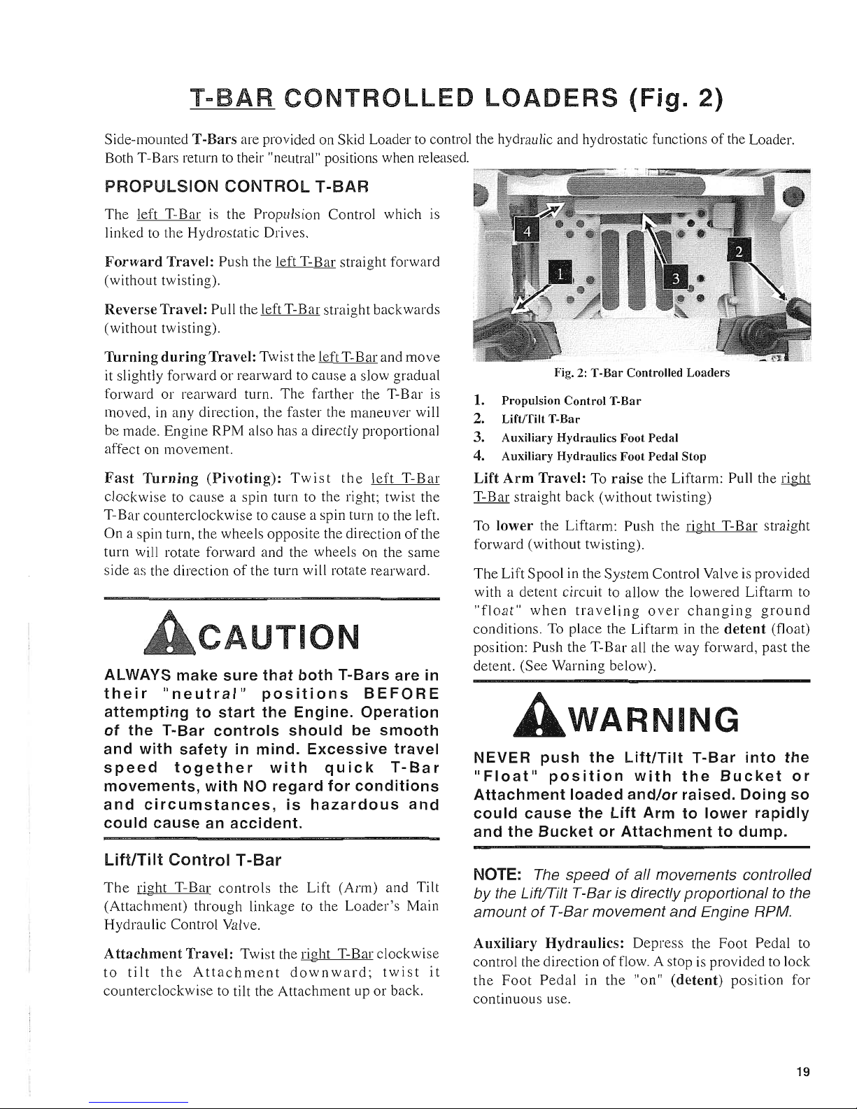
-"llll~-
Fig.
2:
T-Bar Controlled Loaders
1. Propulsion Control T-Bar
2.
Lift/Tilt T-Bar
3. Auxiliary Hydraulics Foot Pedal
4. Auxiliary Hydraulics Foot Pedal Stop
Lift
Arm
Travel:
To
raise
the Liftarm: Pull the right
T-Bar straight back (without twisting)
To
lower
the Liftarm: Push the right T-Bar straight
forward (without twisting).
The Lift Spool in the System Control Valve is provided
with a detent circuit to allow the lowered Liftarm to
"float"
when
traveling
over
changing
ground
conditions. To place the Liftarm in the
detent
(float)
position: Push the T-Bar all the way forward, past the
detent. (See Warning beloW).
WARNING
NEVER
push
the
Lift/Tilt
T-Bar
into
the
"Float"
position
with
the
Bucket
or
Attachment
loaded
and/or
raised.
Doing
so
could
cause
the
Lift
Arm
to
lower
rapidly
and
the
Bucket
or
Attachment
to
dump.
NOTE:
The speed
of
aI/ movements control/ed
by
the LiftlTilt T-Bar is directly proportional
to
the
amount
of
T-Bar movement and Engine RPM.
Auxiliary
Hydraulics:
Depress the Foot Pedal to
control the direction
of
flow. A stop is provided to lock
the
Foot
Pedal
in the "on"
(detent)
position
for
continuous use.
19
Page 22
HAND
&
FOOT
CONTROLLED
LOADERS
(Figs.
3 &
4)
Both right
and
left T-Bars are used
to
control forward and reverse travel of the Loader. The T-Bars are also used for
making turns by moving one T-Bar fmther than the other. Foot Pedals are used
to
control Liftarm and Attachment
movements.
PROPULSION CONTROL
T-BARS
NOTE:
Moving the T-Bars equally in the same
direction will result
in
traveling straight ahead
or
backward.
Forward
Travel: Push both T-Bars straight forward,
slowly
in
the same direction (without twisting).
Reverse
Travel:
Pull
both T-Bars straight back,
slowly and
in
the same direction (without twisting).
Turning
during
Travel: Move one T-Bar farther
forward
or
rearward
than the other T-Bar. Turn
direction is determined by which
T-
Bar
is
moved the
furthest; for example: to turn left, move right
T-
Bar
further than left.
Fast
Turning
(Pivoting): Move one T-Bar in the
opposite direction
of
the other. Turn direction is
determined by which
T-
Bar
is
moved forward; for
example: to pivot turn to the left, move the right T-Bar
forward and the left T-Bar rearward.
Auxiliary
Hydraulics:
Twist the right T-Bar to control
the direction
of
flow. A lock
is
provided for retaining
the right T-Bar in the auxiliary hydraulics "on"
(detent) position for continuous use.
NOTE:
Speed
of
motion is determined
by
how
far
and
fast the T-Bars are moved away from
neutral
and
engine speed.
20
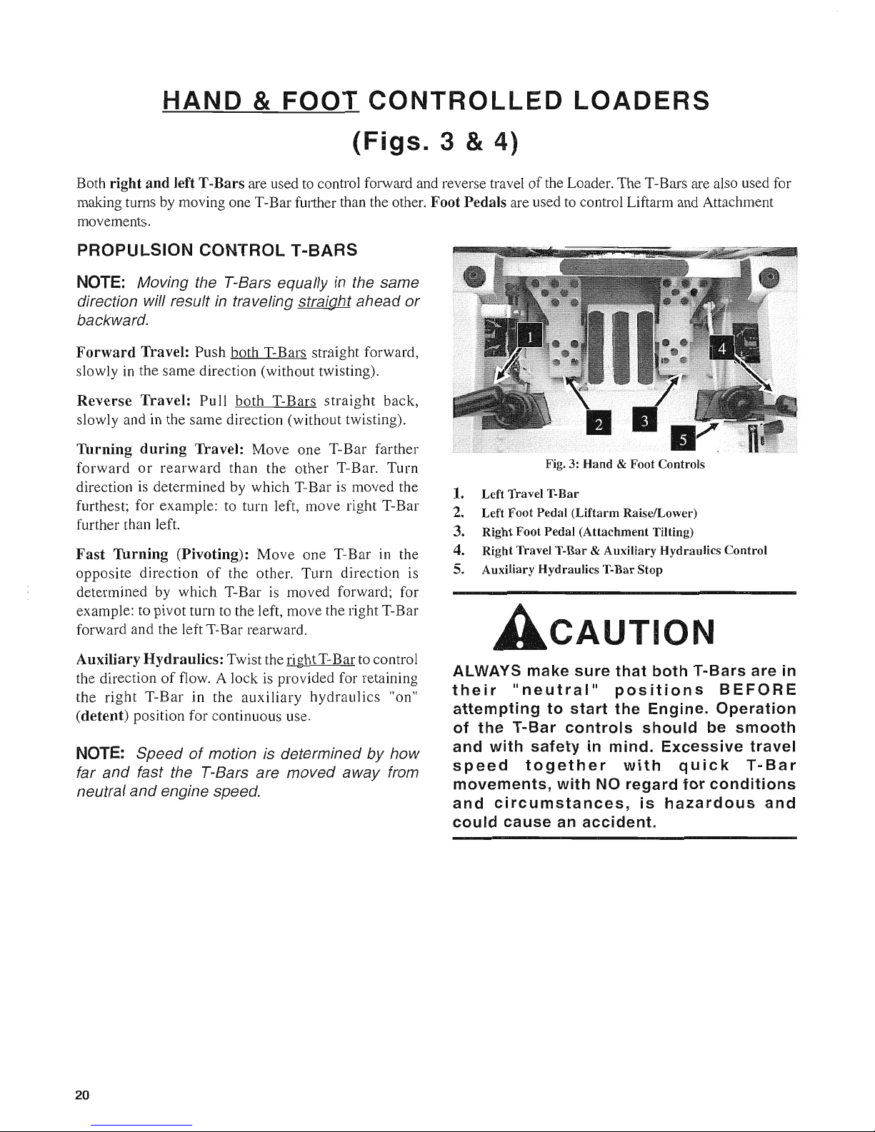
Fig. 3: Hand & Foot Controls
1. Left Travel T-Bar
2.
Left Foot Pedal (Liftarm RaiselLower)
3. Right Foot Pedal (Attachment Tilting)
4. Right Travel T-Bar & Auxiliary Hydraulics Control
5. Auxiliary Hydraulics T-Bar Stop
ACAUTION
ALWAYS
make
sure
that
both
T-Bars
are
in
their
"neutral"
positions
BEFORE
attempting
to
start
the
Engine.
Operation
of
the
T-Bar
controls
should
be
smooth
and
with
safety
in
mind.
Excessive
travel
speed
together
with
quick
T-Bar
movements,
with
NO
regard
for
conditions
and
circumstances,
is
hazardous
and
could
cause
an
accident.
Page 23
HAND
&
FOOT
CONTROLLED
LOADERS
(continued)
LlFTITIL T CONTROL FOOT PEDALS
Attachment
Travel: The right Foot Pedal controls the
tilting motion
of
the attachment.
To
tilt the attachment
rearward, use your heel to push down on the rear
of
the
right Pedal; to tilt the attachment forward, use your toe
to push down on the front
of
the right Pedal.
Liftarm
Travel: The left Foot Pedal controls the
raising and lowering motion
of
the Liftarm.
To
raise the Liftarm, use your heel to push down on
the rear
of
left Foot Pedal.
To
lower the Liftarm, use your toe to push down on
the front
of
the left Pedal.
The Lift Spool in the System Control Valve
is
provided
with a detent circuit to allow the lowered Liftarm
to
"float"
when
traveling
over
changing
ground
conditions.
To
place the Liftarm in the
detent
(float)
condition, use your toe to push the left Foot Pedal all
the way down, past the detent. (See Warning below).
AWARNING
NEVER
push
the
Lift/Tilt
T-Bar
into
the
"Float"
position
with
the
Bucket
or
Attachment
loaded
and/or
raised.
Doing
so
could
cause
the
Lift
Arm
to
lower
rapidly
and
the
Bucket
or
Attachment
to
dump.
NOTE:
Speed
of
motion
is
directly proportional
to
the amount
of
Foot Pedal movement
and
Engine RPM.
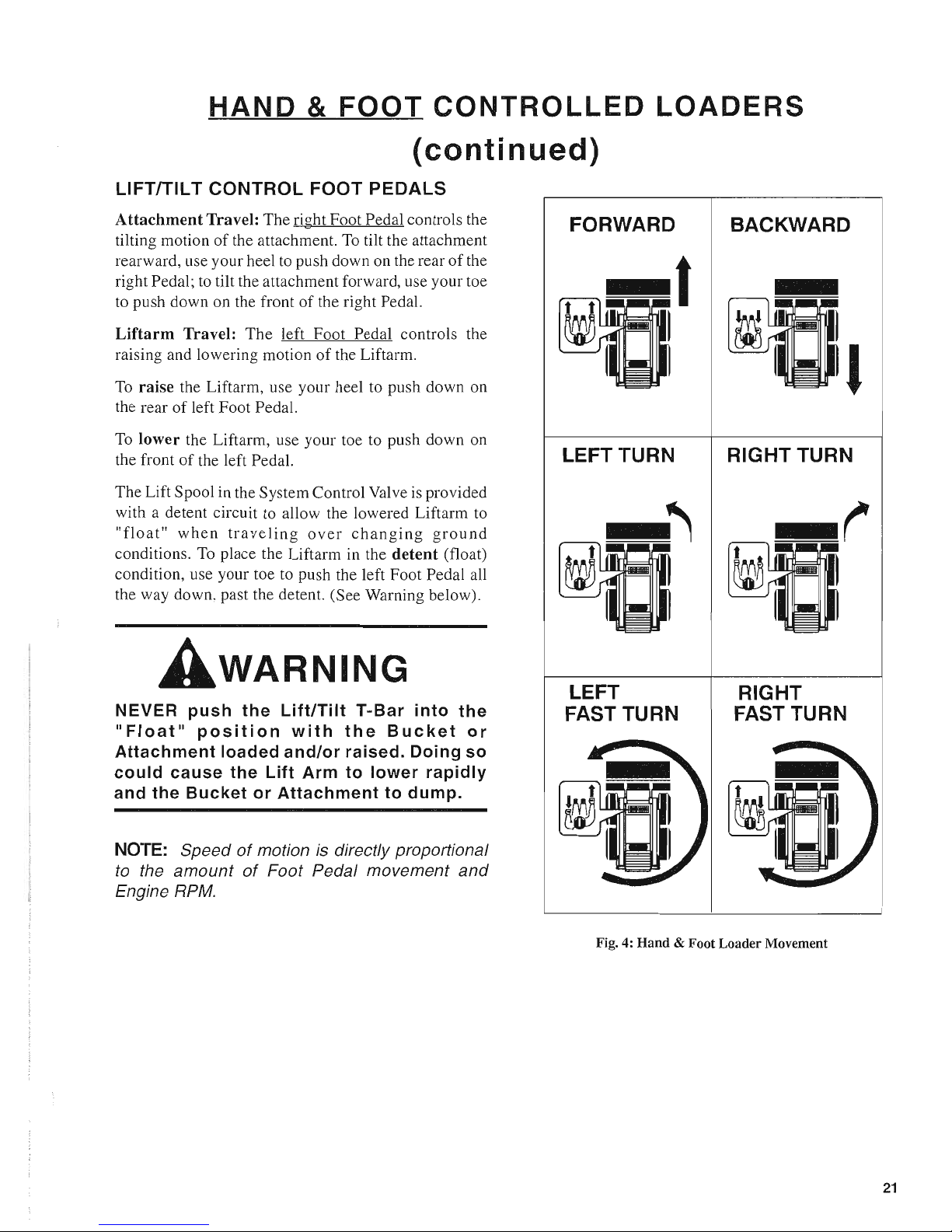
FORWARD
t
LEFT TURN
LEFT
FAST TURN
BACKWARD
I
RIGHT TURN
RIGHT
FAST TURN
Fig. 4:
Hand
& Foot Loader Movement
21
Page 24
Page 25
Page 26
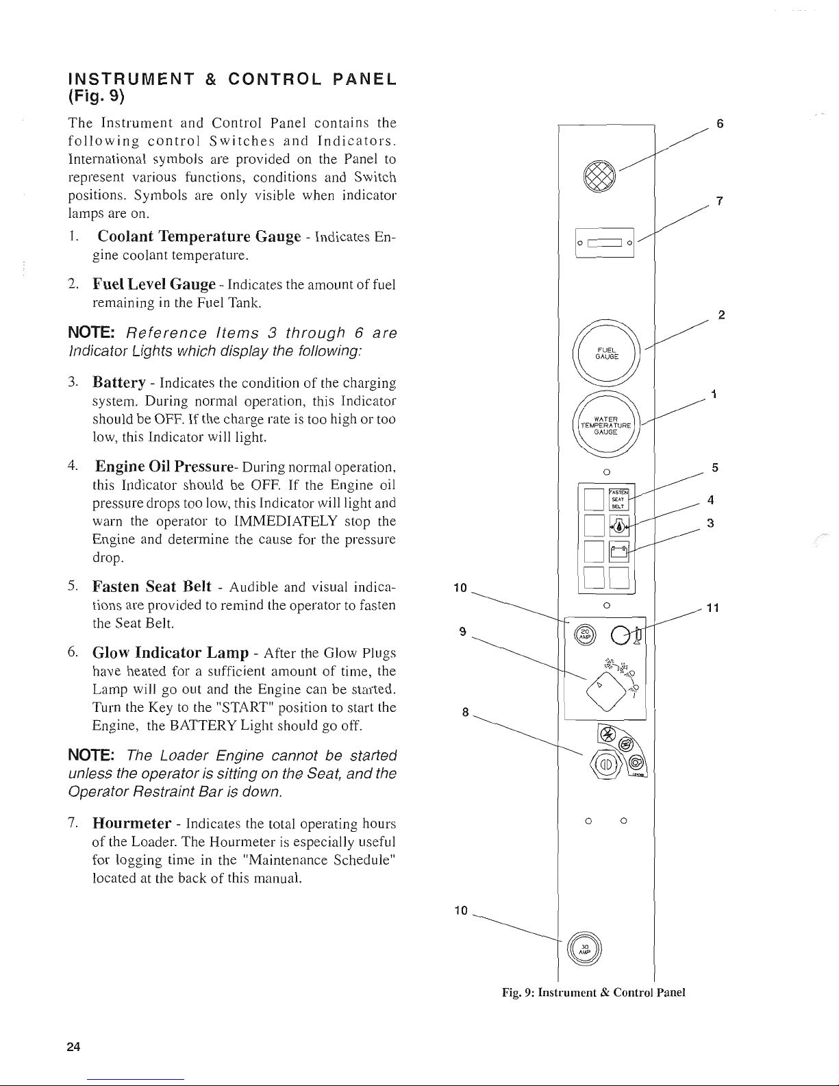
INSTRUMENT
&
CONTROL
PANEL
(Fig. 9)
The
Instrument
and
Control
Panel
contains
the
following
control
Switches
and
Indicators.
International symbols are provided on the Panel to
represent various functions, conditions and Switch
positions. Symbols are only visible when indicator
lamps are on.
1.
Coolant Temperature Gauge - Indicates En-
gine coolant temperature.
2.
Fuel Level Gauge -Indicates the amount
offuel
remaining in the Fuel Tank.
NOTE:
Reference
Items 3 through 6 are
Indicator Lights which display the following:
3.
Battery -Indicates the condition
of
the charging
system. During normal operation, this Indicator
should be OFF.
If
the charge rate is too high or too
low, this Indicator will light.
4.
Engine Oil Pressure- During normal operation,
this Indicator should be OFF.
If
the Engine oil
pressure drops too low, this Indicator will light and
warn the operator to IMMEDIATELY stop the
Engine and determine the cause for the pressure
drop.
5.
Fasten Seat Belt - Audible and visual indica- 10
tions are provided to remind the operator to fasten
the Seat Belt.
6.
Glow
Indicator
Lamp
- After the Glow Plugs
have heated for a sufficient amount
of
time, the
Lamp will go out and the Engine can be started.
Turn the Key to the "START" position to start the
Engine, the BATTERY Light should go off.
NOTE:
The
Loader Engine cannot be started
unless the operator is sitting on the Seat,
and
the
Operator Restraint
Bar
is down.
7.
Hourmeter
- Indicates the total operating hours
of
the Loader. The Hourmeter is especially useful
for logging time in the "Maintenance Schedule"
located at the back
of
this manual.
24
9
8
10
o
o
o o
Fig.
9:
Instrument & Control Panel
6
7
2
1
5
4
3
11
Page 27
8.
Keyswitch -
International
symbols,
located
around the perimeter
of
the Keyswitch, denote the
functions and positions that the Key can be rotated
to. In a clockwise rotation, these positions are:
Off
Position - When the Key is vertical in the
Keyswitch, power from the Battery
is
disconnected
to
the Control and Instrument Panel electrical circuits.
Also, this
is
the only position in which the Key can be
inserted or removed from the Keyswitch.
On
or
Run
Position - When the Key is turned one
position clockwise from the vertical (OFF) position,
power from the Battery
is
supplied to all Control and
Instrument Panel electrical circuits.
Start
Position -When
the
Key
is
turned
fully
clockwise and held in that position, the electric Starter
will be energized for starting the Engine. Release the
Key
as
soon
as
the Engine starts (it will return to the
RUN position by itself).
NOTE: The Key
MUST
a/ways be returned
to
the
Off
position between starting attempts.
9.
Light
Switch - Controls all lights (standard and
optional) on the Loader. International symbols denote the four positions
of
the Light Switch. In a
clockwise direction these are: Off, Flashers, Headlight/Taillight with Flashers, and Headlight/Tail-
light
only.
For
the
Lights
to
function,
the
Keyswitch MUST be in the "On"(Run) position.
1
O.
Fuses, &
Flasher
- Two Fuses are provided on
the Instrument Panel to protect the Loader electrical circuits. Easy access to the Fuses
is
provided
by simply removing the Fuse Caps. An SAE 30
ampere Fuse protects the main wiring circuit, and
an SAE 20 ampere Fuse protect the Lighting circuit, and indicator lamps. Easy access to the
Heavy-duty Flasher,
if
so equipped is provided by
simply removing the Access Cover.
NOTE: Do
NOT
attempt
to
defeat the fusing
by
jumping across the Fuse
or
by
using a higher
amperage Fuse.
11.
Horn
- (Optional): A Horn Kit is available for
installation on the Skid Loader.
25
Page 28
INTERLOCKS
ACAUTION
NEVER
attempt
to
defeat
the
interlock
system
functions
by
mechanically
or
electrically
bypassing
any
Switches,
Relays or Solenoid Valves.
With operator safety in mind, interlock systems are
used on the Loader. Together with Solenoid Valves
Switches and Relays, the interlocks:
Prevent starting
of
the Engine unless the operator
is sitting on the Seat, and the Operator Restraint
Bar
is down.
Disable Lift Arm and Attachment Tilt anytime the
operator leaves the Seat, turns the Keyswitch to
"Off" or raises the Restraint Bar.
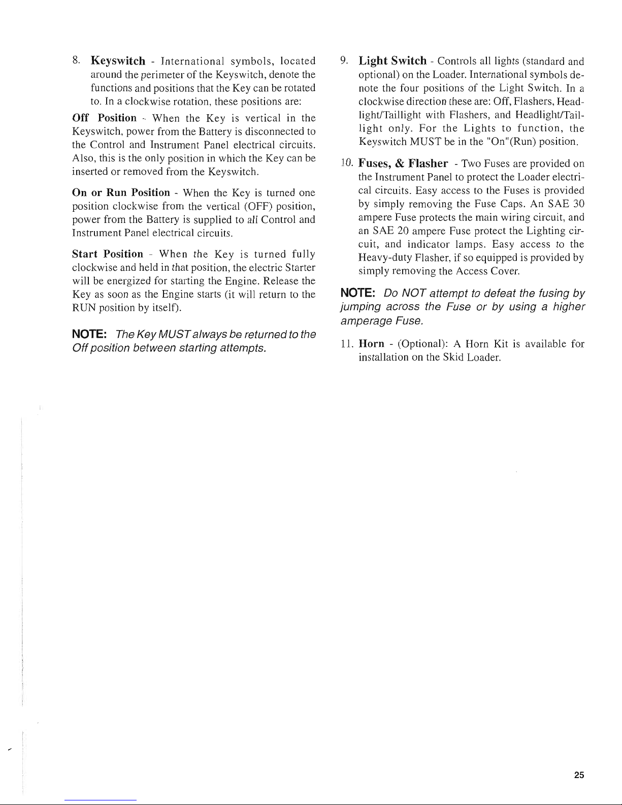
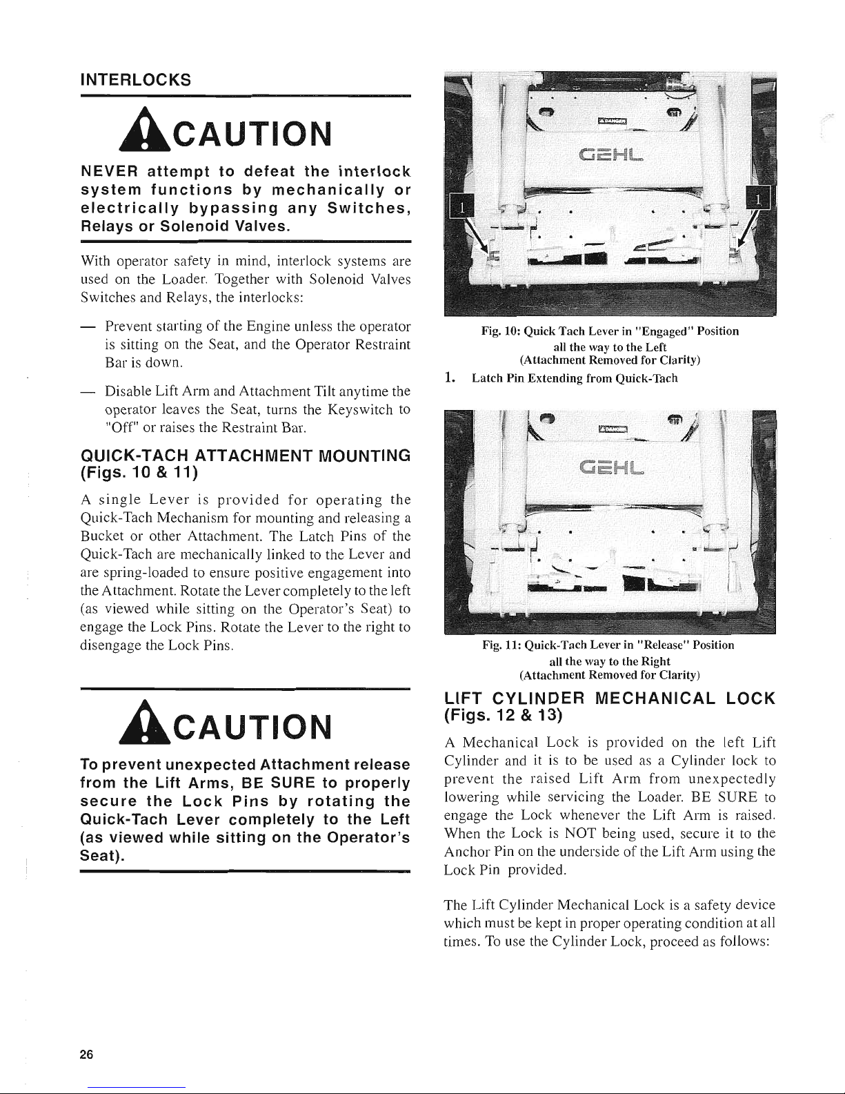
QUICK-TACH ATTACHMENT MOUNTING
(Figs. 10
& 11)
A
single
Lever
is
provided
for
operating
the
Quick-Tach Mechanism for mounting and releasing a
Bucket or other Attachment. The Latch Pins
of
the
Quick-Tach are mechanically linked
to
the Lever and
are spring-loaded to ensure positive engagement into
the Attachment. Rotate the Lever completely to the left
(as viewed while sitting on the Operator's Seat) to
engage the Lock Pins. Rotate the Lever to the right to
disengage the Lock Pins.
ACAUTION
To
prevent
unexpected
Attachment
release
from the Lift Arms, BE SURE to properly
secure
the
Lock
Pins
by
rotating
the
Quick-Tach Lever
completely
to the Left
(as viewed while sitting on
the
Operator's
Seat).
26
1.
Fig. 10: Quick Tach Lever in "Engaged" Position
all the way to the Left
(Attachment Removed for Clarity)
Latch Pin Extending from Quick-Tach
! • •
"-
_~'
411'_
.In·
mi
Fig. 11: Quick-Tach Lever in "Release" Position
all the way to the Right
(Attachment Removed for Clarity)
LIFT
CYLINDER
MECHANICAL
LOCK
(Figs. 12 & 13)
A
Mechanical
Lock
is
provided
on the left
Lift
Cylinder and it is to be used as a Cylinder lock to
prevent
the
raised
Lift
Arm
from
unexpectedly
lowering while servicing the Loader.
BE
SURE
to
engage the Lock whenever the Lift Arm
is
raised.
When the Lock
is
NOT being used, secure it to the
Anchor Pin on the underside
of
the Lift Arm using the
Lock Pin provided.
The Lift Cylinder Mechanical Lock is a safety device
which must be kept in proper operating condition at all
times. To use the Cylinder Lock, proceed as follows:
Page 29

AWARNING
BEFORE
leaving
the
Operator's
Compartment
to
work
around the
outside
of
the
Loader
with
the
Lift Arm
raised,
ALWAYS
engage
the
Lift
Cylinder
Mechanical Lock. Also, turn
the
Keyswitch
to
the
Off position, remove the Key and
take
it with you.
Lock Engagement
To engage the Lift Cylinder Mechanical Lock, proceed
as follows:
I. Apply the Parking Brake.
2.
Lower the Lift Arm into contact with the Loader
Frame.
3.
Turn the Keyswitch to the
Off
position to Stop the
Engine, remove the Key and take it with you.
4.
Leave the Operator's Compartment and remove
the Lock Pin which holds the Lock up against the
Lift Arm. Allow the Lock to come down into
contact with the Lift Cylinder.
5.
Return to the Operator's Compartment and restart
the Engine.
6.
Move the Lift Control to raise the Lift
Arm
until
the Lock drops over the end
of
the Lift Cylinder
and around the Cylinder Rod. Then, slowly lower
the Lift Arm until the free-end
of
the Lock contacts
the top end
of
the Lift Cylinder.
7.
Look to make sure that the Lock is secure against
the Cylinder End. Then, stop the Loader Engine
and leave the Operator's Compartment.
Jt"11
Fig. 12: Lift
Arm
raised & Lock
"Engaged"
1.
LiftArm
2. Lift Cylinder Mechanical Lock
"Engaged"
3. Lock Pin
4. Left Side Lift Cylinder
5.
Anchor
Pin
Lock Disengagement
WARNING
NEVER
attempt
to
disengage
the
Lift
Cylinder
Lock by leaving
the
Operator's
Compartment
while
the
Engine is running.
To return the Lift Cylinder Mechanical
Lock
to its
"storage" position, proceed as follows:
1.
Apply the Parking Brake.
2.
Raise the Lift Arm completely.
3.
Turn the Keyswitch to the
Off
position to Stop the
Engine, remove the Key and take it with you.
ACAUTION
BEFORE
performing
Step 4, below, MAKE
SURE
the
area BELOW the Lift Arm and
Attachment
is clear.
4.
Before
leaving
the
Operator's
Compartment,
check to make sure that the Lift Arm is being held
in the raised position by the Solenoid Valve (See
the following NOTE).
27
Page 30

NOTE: With the Keyswitch OFF,
and
if
the
Solenoid Valve is working properly, the Arm
should remain in the raised position when the Lift
Control is moved forward.
If
the Valve does
NOT
hold the Arm and the Arm begins
to
lower, do NOT
leave the Operator's Compartment. Instead, have
another person place the Lock into the "storage"
position for you. Then, contact your Gehl dealer
to
determine the reason why the Lift Arm lowers
while the Keyswitch
is
in
the "off" position.
5.
To
store the Lock, raise it up until it contacts the
Lift Arm and install the Lock Pin through the hole
in
the Lock Anchor Pin under the Lift Arm.
AUXILIARY HYDRAULICS
Standard
Flow
Auxiliary
Hydraulics
(Fig. 14)
Loaders are shipped from the factory with standard
flow Auxiliary Front Hydraulic connections. A pair
of
Quick-disconnect Fittings, located at the left, inside
corner
of
the Lift Arm, can be used for operating
Attachments (Grapple, Backhoe, etc.).
T-Bar Controlled Loaders: A Footpedal
is
used to
control the direction
of
oil flow. A stop is provided
to
lock the footpedal for continuous operation.
Hand/Foot Controlled Loaders: the right T-Bar
is
twisted to control the direction
of
oil flow. A stop
is
provided to lock the T-Bar for continuous operation.
High
Flow
Auxiliary
Hydraulics
(Fig. 15)
In addition to standard flow Auxiliary Front Hydraulic
connections, model 5625DX Loaders are shipped from
the factory with High Flow Auxiliary Hydraulics. An
additional pair
of
Quick-disconnect Fittings, located
at
right and left front corners
of
the Lift Arm, can be used
for operating high hydraulic oil flow Attachments
(Cold Planer, Snowblower, etc.).
A two-position, Toggle Switch is used to control the
operation
of
the High Flow Hydraulics. The two
positions on the Toggle Switch are:
OFF
- which disables output to the Quick-disconnect
Fittings.
ON
- which pressurizes the Top Male Port.
28
Fig. 13: Lift Arm Lowered & Lock "Stored"
1.
Lift Cylinder Mechanical Lock in
"Storage"
Position
2.
Lock Pin
3.
Left Side Lift Cylinder
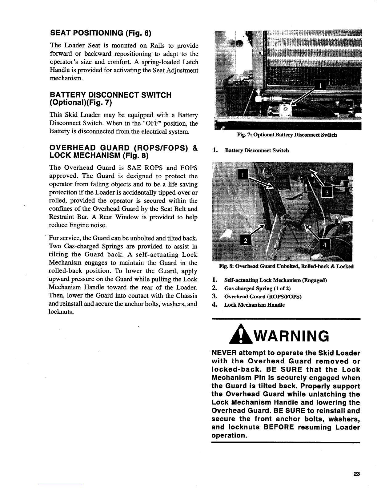
Fig. 14:
Standard
Flow Auxiliary Hydraulics
1.
Standard
Flow Quick-disconnects
Fig.
15:
High Flow Auxiliary Hydraulics
1.
High Flow Auxiliary Hydraulics Control Switch
2.
High Flow Quick-disconnects
3. Case
Drain
Line
Page 31

CHAPTER
6
OPERATION
GENERAL
INFORMATION
(Fig. 16)
CAUTION
BEFORE
starting
the
Engine
and
operating
the
Loader,
review
and
comply
with
ALL
safety
recommendations
set
forth
in
the
SAFETY
chapter
of
this
manual.
Know
how
to
STOP
the
Loader
BEFORE
starting
it.
Also,
BE
SURE
to
fasten
and
properly
adjust
the
Seat
Belt
and
lower
the
Operator
Restraint
Bar.
BEFORE STARTING ENGINE
Before
starting the Engine and running the Loader,
refer to the "Controls & Safety Equipment"
Chapter
and
familiarize
yourself
with the various operating
controls, Indicators and safety devices on the Loader.
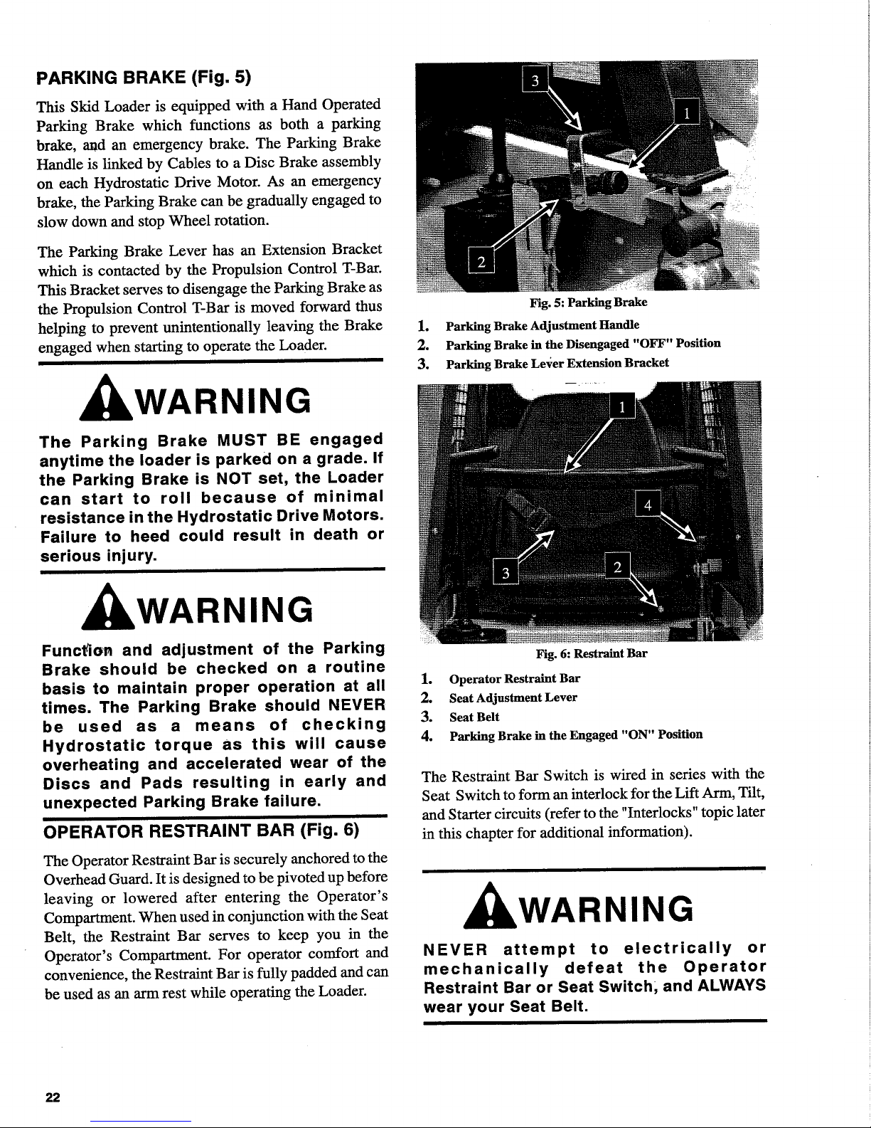
Fig. 16: Operator's Compartment
1.
Operator's
Seat
2.
Operator
Restraint
Bar
3. Seat Belt
4. Parking Brake in the Engaged
"ON"
Position
STARTING THE ENGINE
WARNING
ALWAYS
fasten
your
Seat
Belt
and
lower
the
Restraint
Bar
BEFORE
starting
the
Loader
Engine.
Leave
the
Parking
Brake
"engaged"
until
the
Engine
is
running
and
you
are
ready
to
operate
the
Loader.
The
following
procedure
is
recommended
for starting
the
Loader
Engine:
1.
Carefully step up onto the
back
of
the
Bucket
or
Attachment
while grasping the Handles to
get
into
the
Operator's
Compartment.
2.
Fasten
the
Seat
Belt
and
lower
the Restraint Bar.
3.
Check
that both Control T-Bars are in their "Neu-
tral" positions.
4.
Push
the Throttle forward to
half
of
full speed.
NOTE:
When the Key
is
turned
to
liON
II
position,
a Buzzer will sound momentarily.
5.
Turn
the Keyswitch to the "ON" position.
Wait
for
the
Glow
Indicator
Light
to go out, then turn the
key
to the start position.
NOTE:
Crank the Starter until the Engine is
started.
If
the Engine fails
to
start within
15
sec-
onds, return the key
to
the "Off" position, wait 2
minutes,
and
try
to
restart
the
Engine.
Cranking the engine for longer than 15 seconds
will result in premature failure
of
the Starter.
After
the
Engine
starts, allow a sufficient
warm-up
time
before
attempting to operate the Controls.
COLD
STARTING PROCEDURES
A
Block
Heater
or
Lower
Radiator
Hose
Heater
is
recommended
for starting in temperatures
of
20°F
or
lower.
See
your
Gehl
Dealer
for
recommended
Heater.
29
Page 32

STOPPING THE LOADER
The following procedure is the recommended sequence for stopping the Loader:
1.
Check that Propulsion Control T-Bar(s) are in the
"Neutral" position.
2.
Using the Lift/Tilt Control, lower the Lift Arm and
rest the Attachment on the ground.
3.
Pull the Throttle Lever back to the Idle position
(and/or take
your
foot
off
the Accelerator Pedal
for
T-Bar controlled machines).
4.
Turn the Keyswitch Key
to
the
Off
position
to
shut
the Engine off.
5.
Apply the Parking Brake, Raise the Restraint Bar,
unlatch the Seat Belt and grasp the Handles while
climbing out
of
the Operator's Compartment.
AWARNING
The
Parking
Brake
MUST
BE
engaged
anytime
the Loader is parked on a grade. If
the Parking Brake
is
NOT
set, the Loader
can
start
to
roll
because
of
minimal
resistance in the
Hydrostatic
Drive Motors.
Failure to heed could result in death or
serious injury.
30
LOADER MOVEMENT
The Hydrostatic Drive
of
the Skid Loader controls
forward and reverse direction and speed. As rapidly as
the Propulsion Control(s) are moved to the straight
"N
eutral" position, movement
of
the Wheels
is
slowed
accordingly.
ACAUTION
A
combination
of high heat and
excessive
loads may
cause
the
engine
to
overheat.
See
the
Troubleshooting
chapter
in this
manual
for
further
instruction.
ACAUTION
Operate
the Propulsion Controls
gradually
and
smoothly
when
starting,
stopping,
turning and reversing Loader
directions.
Excessive
speed
can
be
hazardous.
ALWAYS
exercise
caution
and
good
judgment
while
operating
the
Skid Loader.
Page 33

First
Time
Operation
CAUTION
BE
SURE
the
area
being
used
for
test-running
is
clear
of
spectators
and
obstructions.
For
the
first
time,
operate
the
Loader
with
an
empty
Bucket.
Smoothest and most efficient Loader operation is
achieved while running the Engine at half-throttle.
Make sure the Engine is warm and then, follow instructions appropriate for your type
of
Loader.
T-Bar Controlled Loaders (Fig. 17): Using your right
hand, slowly and smoothly pull straight back on the
Lift/Tilt Control T-Bar to raise the Lift Arm. Twist the
T-Bar to roll the Bucket forward or back. Attempt all
raising and lowering functions, and combinations
of
the two functions before proceeding to operate the
Propulsion Control T-Bar. ALWAYS lower the Lift
Arm and roll the Bucket back
BEFORE
proceeding to
operate the Propulsion T-Bar.
Using your left hand, slowly and smoothly move the
Propulsion Control T-Bar straight forward to travel
ahead. Then, slowly pull the T-Bar backward to "Neutral" to stop forward movement.
To
travel backwards,
slowly and smoothly move the T-Bar straight back.
Then, return the Propulsion Control T -
Bar
to the "Neutral" position to stop reverse movement. Next, twist the
Propulsion T-Bar slowly clockwise to turn right and
counterclockwise to turn left. Attempt all forward,
reverse and turning movements before proceeding to
operate both T -Bars at the same time.
Fig.
17:
T-Bar Controlled Loaders
1. Propulsion Control
T-Bar
2. Auxiliary Hydraulics Control Footpedal
3. Foot Throttle
4.
Hand
Throttle
5. LiftlTilt Control
T-Bar
6.
Parking
Brake
Fig. 18: Hand
& Foot Controls
1. Left Propulsion Control T-Bar
2. Right Propulsion Control T-Bar & Auxiliary Hydraulics
3. Hand Throttle
4. Attachment Tilting (right foot pedal)
5. Attachment Lifting (left foot pedal)
6.
Parking
Brake
31
Page 34

Hand & Foot Controlled Loaders (Fig. 18): To raise
the Liftarm, use your heel to push down on the rear
of
the left Foot Pedal. To lower the Liftarm, use your toe
to push down on the front
of
the left Pedal.
The right Foot Pedal controls the tilting motion
of
the
attachment. To tilt the attachment rearward, use your
heel to push down on the rear
of
the right Pedal: to tilt
the attachment forward, use your toe to push down on
the front
of
the right Pedal.
Attempt all raising and lowering functions, and combinations
of
the two functions before proceeding to
operate the Propulsion Control T -Bars. AL WAYS
lower the Lift Arm and roll the Bucket back before
proceeding to operate the Propulsion T-Bars.
Using both hands, slowly and smoothly move the
Propulsion Control T -Bars straight forward to travel
ahead. Then, slowly pull the T-Bars backward to "Neutral" to stop forward movement. To travel backwards,
slowly and smoothly move the T-Bars straight back.
Then, return the T-Bars to the "Neutral" position to
stop reverse movement.
To Turn during Travel: Move the right T-Bar further
forward then the left to turn left. Move the left T -Bar
further forward than the right to turn right.
To Pivot: Move the right T-Bar forward and the left
T -Bar rearward to pivot to the left. Move the left T -Bar
forward and the right T-Bar rearward to pivot to the
right.
Skid Loader operating skills are only obtained through
proper coordination
of
the Loader's forward and re-
verse movements, with raising and lowering the Lift
Arm and with rolling the Bucket forward and back. To
gain proficiency, practice all Control T-Bar operations
until you are capable
of
performing the movements
without mistake or hesitation.
NOTE:
If
the Loader Engine kills while either
T-Bar
is
being operated, the T-Bar must be re-
turned
to
its "Neutral" position before the Engine
can be restarted.
32
ACAUTION
BEFORE
leaving
the
Operator's
Compartment,
engage
the
Parking
Brake.
BE SURE
to
lower
the
Lift
Arm
or
engage
the
Lift
Cylinder
Mechanical
Lock,
as
appropriate.
Shut
the
Engine
off,
and
remove
the
Key.
NOTE:
If
the Loader will not start, the Uftarm can
be lowered
by
sitting in the Operator's Seat with
the Restraint Bar down, and turning the Key
to
the
"ON" position, then lowering the Uftarm.
PARKING
BRAKE
(Figs.
16, 17, & 18)
AWARNING
Function
and
adjustment
of
the
Parking
Brake
should
be
checked
on a routine
basis
to
maintain
proper
operation
at
all
times.
NEVER
use
the
Parking
Brake
as
a
means
of
checking
Hydrostatic
torque
as
this
will
cause
overheating
and
accelerated
wear
of
the
Discs
and
Pads
resulting
in
early
and
unexpected
Parking
Brake
failure.
NOTE:
The
Parking Brake
is
NOT designed
for,
NOR intended
to
be used
as,
the primary means
of
stopping forward
or
reverse movement
of
the
Loader.
The
Propulsion Control T-Bar(s), when
returned
to
the "Neutral" position, provide Hydrostatic braking and are the primary means for
stopping Loader movement.
The proper sequence for correct Loader operation
is
to
always engage the Parking Brake before shutting off
the Loader Engine or to disengage the Brake ONLY
after the Engine is running and you are ready to move
the Propulsion T-Bar(s). In an EMERGENCY, when
it becomes necessary to STOP the Loader forward or
reverse movement, IMMEDIATELY, pull up on the
Parking Brake.
Page 35

CHANGING ATTACHMENTS (Fig. 19)
WARNING
To
prevent
unexpected
Attachment
release
from
the
Lift
Arm,
BE
SURE
to
properly
secure
the
Quick-Tach
Mechanism
Lock
Pins
by
rotating
the
Latch
Lever
all
the
way
to
the
left.
The Skid Loader features a Quick-Tach Latching and
Locking Mechanism for mounting an Attachment to
the front
of
the Lift Arm. The Quick-Tach mechanism
uses a single Latch Lever control for attaching and
detaching the Attachment.
Attaching
l.
Rotate the Latch Lever completely to the right (as
viewed from the Operator's Compartment) to fully
retract the Latchpins.
2.
Start the Loader Engine and make sure the Lift
Arm is lowered and in contact with the Loader
Frame.
3.
Align the Loader squarely with the back
of
the
Attachment.
4.
Roll the Quick-Tach mechanism forward until the
mating parts
of
the mechanism are in-line with and
slightly below the Hooks on the back
of
the At-
tachment.
5.
Slowly drive the Loader forward and, at the same
time, roll the Quick-Tach mechanism back to engage the Hooks on the Attachment.
6.
Stop forward travel when the Hooks are engaged
but, continue to roll the Quick-Tach mechanism
back to pick the Attachment up
off
the ground.
Exercise the
MANDATORY
SAFETY
SHUT-
DOWN
PROCEDURE
(page
10).
7.
With the Loader Engine OFF, leave the Operator's
Compartment, and swing the Latch Lever completely to the left (as viewed from the Operator's
Compartment) to fully engage the Latchpins.
8.
To check that the Attachment is properly installed,
apply down pressure to the Attachment prior to
operating.
Fig. 19: Quick-Tach
1. Quick-
Tach
Lever Locked (all the way to the Left)
2. Quick-
Tach
Lock Pin
Detaching
l.
Roll the Quick-Tach mechanism backward until
the Attachment is
off
the ground. Exercise the
MANDATORY
SAFETY
SHUTDOWN
PRO-
CEDURE
(page 10).
2.
With the Loader Engine OFF, leave the Operator's
Compartment, and rotate the Latch Lever completely to the right (as viewed from the Operator's
Compartment) to fully retract the Latchpins.
3.
Start the Loader Engine and make sure that the Lift
Arm is lowered and in contact with the Loader
Frame.
4.
Roll the Quick-Tach mechanism forward and
slowly back-up the Loader until the Attachment is
free from the Loader.
SELF-LEVELING
Loaders are provided with a hydraulic self-leveling
feature. This feature is designed to keep the attachment
level while the Lift
Arm
is being raised.
33
Page 36

MATERIAL
DENSITIES
The Table at the right lists densities for some common
materials which could be carried in a Bucket. The
densities listed are average values and intended only
as a guide for Bucket selection. For a material which
is
NOT
in
the Table, obtain its density value before
selecting the appropriate Bucket.
To prevent exceeding the operating capacity
of
the
Loader, use the Table
of
Common Material Densities
to determine the proper size Bucket to use, based on
the type
of
material to be carried.
SAE
OPERATING CAPACITIES
Model
Weight
in
Ibs.
Weight in kg.
5625 1700
771
To use the table, find the material name and see what
its maximum density is. Then, divide the operating
capacity
of
the Loader by the material density to de-
termine the
maximum
size Bucket to use for a heaped
load.
NOTE:
Where the material density is listed as a
range (Clay
at
80-100 Iblff3, for examRle), always
use the maximum density (100
Ibslff
in this example) for making calculations. (Also, see the
following Examples.)
EXAMPLE
1:
If
clay (density
of
80-100 Ibs/ft
3
)
is
to
be hauled using a 5625 Loader, the maximum Bucket
size
is
(1700 Ibs
-+
100 Ibs/ft
3
= 17
cubic
feet
).
Therefore, you could safely use a Bucket that has a
capacity
of
17
cubic
feet
or
less.
EXAMPLE
2:
If
concrete (density
of
115 Ibs/ft
3
)
is
to
be hauled using an 5625 Loader, the maximum Bucket
size is (1700 Ibs
-+
115 Ibs/ft
3
= 14.8 cubic feet).
Therefore, you could safely use a Bucket that has a
capacity
of
14
cubic
feet
or
less.
ACAUTION
NEVER
exceed
the
rated
operating
capacity
of
the
Loader
as
shown
on
the
Capacity
Decal.
34
Table
of
Common
Materials
and
Densities
Density
Material in
3
(lbJft. ) (kglm
3
)
Ashes 35-50 560-800
Brick-common
112
1792
Cement
110
1760
Charcoal
23
368
Clav
80-100 1280-1600
Coal 53-63 848-1008
Concrete
115
1840
Cinders 50 800
Coal-anthracite
I
94 1504
Coke
30
480
Earth-drv loam
30
480
Earth-wet loam
65
1040
Granite 93-111 1488-1776
Gravel-drv
66 1056
Gravel-wet
90
1440
Gvosum-crushed
115
1840
Iron Ore
145
2320
Lime 60 960
Lime Stone 90 1440
Manure-liauid
65
1040
Manure-solid 45 720
Peat-solid 47 752
Phosohate-granular
90
1440
Potash
68
1088
~_uartz-granular
110
1760
Salt-dry
100
1600
Salt-Rock -solid
135
2160
Sand-dry
108
1728
Sand-wet
125
2000
Sand-foundry
95
1520
Shale-crushed
90
1440
I
I Slag-crushed
70
1120
Snow 15-50
240-800
iSuloha
95
1520
Taconite
107
1712
The Specifications Chapter lists the available Buckets
and their capacities to help you determine which size
Bucket to use. You can always use a smaller capacity
Bucket, but NOT a Bucket with greater capacity then
the calculated MAXIMUM unless it is only partially
filled.
Page 37

LOADER OPERATION
(Figs.
20 - 26)
ARNING
ALWAYS
maintain
a
safe
distance
from
electric
power
lines
and
avoid
contact
with
any
electrically
charged
conductor
or
gas
line!
Accidental
Contact
or
rupture
can
result
in
electrocution
or
an
explosion!
Contact
the
"Digger's
Hotline"
or
proper
local
authorities
for
utility
line
locations
BEFORE
starting
to
dig!
Digging
with
and
Loading a Bucket
To dig with and load a Bucket, first lower the Lift Arm
down into contact with the Loader Frame and then roll
the Bucket's Cutting Edge down into contact with the
ground. Move the Loader into material and, as Engine
loads, roll Bucket back slowly and, at same time, pull
back gradually on Propulsion T-Bar(s) to decrease
travel speed while still maintaining Wheel torque.
When attempting to fill the Bucket while working with
most hard-packed materials, it will usually be necessary to raise the Lift Arm while rolling the Bucket
back. Also, avoid driving onto the material to be
picked-up,
if
at all possible.
WARNING
ALWAYS
carry
loaded
Bucket
with
Lift
Arm
resting
on
Loader
Frame.
For
additional
stability
when
operating
on
inclines,
AL
WA
YS
travel
with
heavier
end
of
Loader
to
the
top
of
the
incline.
With the Bucket filled, back the Loader away from the
material and rest the Lift Arm against the Loader
Frame before proceeding to the dumping area.
Dumping
the
Load
Onto a Pile
Carry loaded Bucket as low as possible until reaching
the pile. Slowly stop forward motion and raise the Lift
Arm high enough so that the Bucket clears the top
of
the pile. Then, slowly move the Loader ahead to position the Bucket to dump the material on top
of
the pile.
Empty the Bucket and back the Loader away while
lowering the Lift Arm and rolling the Bucket back.
Fig. 20: Loading the Bucket
Fig. 21: Digging in Hard-packed Materials
Fig. 22: Digging in Loose Materials
35
Page 38

AWARNING
NEVER push the Controls into the "Float"
position with the
Bucket
or
Attachment
loaded
and/or
raised.
Doing
so
could
cause the Lift Arm to lower rapidly and the
Bucket or Attachment to dump.
Dumping the
load
Into a Box
Carry the loaded Bucket low and approach the truck,
trailer or spreader box squarely with the side
of
the
box. Stop your approach
as
close to the side
of
the box
as
possible while still allowing clearance for raising
the Lift Arm and loaded Bucket. Then, raise the Lift
Arm until the Bucket clears the top
of
the box and
move the Loader ahead to position the Bucket over the
inside
of
the box. After the material
is
dumped, back
away from the box and lower the Lift Arm while
rolling the Bucket back.
Dumping
the
load
Over
a
Solid
Embankment
ACAUTION
Do NOT drive too close to an excavation or
ditch; BE SURE the surrounding ground
has
adequate
strength
to
support
the
weight of the Loader and the load.
Carry the loaded Bucket
as
low
as
possible while
traveling toward the dumping area. Stop the Loader at
the position where the Bucket extends half-way over
the edge
of
the embankment. Then, roll the Bucket
forward and raise the Lift Arm to dump the material.
After the material
is
dumped, back away from the
embankment while lowering the Lift Arm and rolling
the Bucket back.
Scraping with a Bucket
For scraping, the Skid Loader should be operated in
the forward direction. First, position the Lift Arm
down against the Loader Frame. Tip the Bucket Cutting Edge at a slight angle to the surface being scraped.
While traveling slowly forward, with the Bucket in this
position, material can flow over the Cutting Edge and
collect inside the Bucket.
36
Fig. 23: Carrying the Load
Fig. 24: Positioning Bucket for Scraping
Fig. 25: Scraping with a Bucket
Page 39

Leveling with a Bucket
First drive the Loader to the outer edge
of
the area to
be leveled. Then, with the Lift Arm down against the
Frame, push the Lift/Tilt T-Bar
(TBar
Controlled
Loaders),
or Left Foot Pedal(Hand & Foot Controlled
Loaders),
into the "float" position and roll the Bucket
forward to place the Bucket Cutting Edge at a 30 to 45
degree angle to the surface being leveled. Proceed to
drive the Loader backwards dragging the dirt and, at
the same time, leveling it.
NOTE:
The
"f/oat" (detent) position for T-Bar
Controlled Loaders is reached
by
pushing the
right T-Bar all the way forward. For Hand -Foot
Controlled Loaders use your toe
to
push the front
of
the left Foot Pedal all the way down. This
position opens both work ports
to
the Reservoir
and thus allows the Lift Arm
to
"f/oat" while the
Bucket follows the ground contour.
Fig. 26: Leveling with a Bucket
37
Page 40

HIGHWAY TRAVEL (Fig. 27)
When it becomes necessary to frequently move the
Loader over long distances, obtain and use a properly
rated
Loader
Trailer.
For
short distance highway
travel, attach a SMV (Slow Moving Vehicle) Emblem
(purchased locally) to the back
of
the Loader.
For
highway operation, obtain and install Amber Dual
Flashers or a Strobe Light.
LIFTING & TIE-DOWN LOCATIONS
(Fig. 27)
Three tie-down Hooks are provided near the bottom
of
the Loader for inserting chains through to secure the
Loader while transporting.
If
the Loader has to be lifted (using a crane), first
purchase Lifting Kit (805805) from your local GEHL
dealer and install it on the front corners
of
the Loader
using the holes provided. At the rear
of
the Loader, two
lifting holes are provided (one on each rear riser).
LONG TERM STORAGE
If
your Skid Loader is to be stored for a long period
of
time, the following procedures are suggested.
l.
Fully inflate Tires.
2.
Lubricate all grease zerks.
3.
Check all fluid levels and replenish as necessary.
4.
Add stabilizer to fuel per fuel suppliers recommendations.
5.
Remove battery, fully charge, and store in a cool,
dry location.
6.
Protect against extreme weather conditions such
as moisture, sunlight, and temperature.
38
Fig. 27: Lifting & Tie Down Locations
1.
Rear
Tie-down Hook Location
(1
each side)
2.
Front
Tie-down Hook Location
3.
Rear
Lifting Hole Location
(1
each side)
4. Lifting Kit Mounting Location
(1
each side)
Page 41

CHAPTER
7
ADJUSTMENTS
LOADER RAISING PROCEDURE
The following procedure should be used to raise the Skid
Loader so that all four (4) Tires ARE
NOT
contacting the
ground.
AWARNING
BEFORE
beginning
this
service
procedure,
exercise
the
MANDATORY
SAFETY SHUTDOWN PROCEDURE
(page 10).
AWARNING
DO NOT rely on a
jack
or hoist to maintain
the
"raised"
position
without
additional
blocking and supports. Serious personal
injury could result from improperly raising
and/or blocking the Skid Loader.
1.
For blocking the Loader, obtain solid wooden blocks
that measure
6"
to
8"
wide and about
12"
long. Obtain
enough so that when stacked, the blocks for each
corner
of
the Loader will measure at least 7 1/2" tall.
The exact quantity will be determined once the
Loader is raised
off
its Tires.
2. Using a
jack
or hoist capable
of
lifting at the fully-
equipped weight
of
the Loader (with all attached
options), lift the rear
of
the Loader until the rear Tires
are
off
the ground.
3.
Place a 7
112"
stack
of
wooden blocks under the flat
part
of
the Loader Chassis. They should run parallel
with, but not touch, the rear Tires. (See Fig. 28)
4.
Slowly lower the Loader so its weight rests on the
blocks.
If
the Tires still touch the ground, raise the
Loader again, and add more blocks, then lower again.
5.
Repeat steps 2 thru 4 for the front end
of
the Loader.
When the procedure is finished, all four Tires should
be off the ground so they can be removed
if
necessary.
(See Fig. 28)
LOADER LOWERING PROCEDURE
1.
When service or adjustment procedures are complete,
the Skid Loader can be taken down from the "raised"
position. Lower the Loader back onto its Tires as
follows:
2.
Using a jack or hoist, raise the front
of
the Loader
until its weight no longer rests on the front blocks.
3.
Carefully remove the blocking under the front
of
the
Loader.
4.
Slowly lower the Loader until the front Tires are
resting on the ground.
5.
Repeat Steps 1 thru 3 for the rear
of
the Loader. When
the procedure is finished, all four (4) Tires should be
on the ground and the blocking should be removed
from under the Loader.
Fig. 28: Skid Loader properly Blocked
(the Tires
and
Wheels
are
removed to show Blocks).
39
Page 42

CAUTI
N
BEFORE
Proceeding
to
perform
any
adjustments
on
the
Skid Loader,
exercise
the
MANDATORY
SAFETY
SHUTDOWN
PROCEDURE
(page
10).
ENGINE
Skid Loaders are provided with separate Engine maintenance manuals which should be consulted for Engine
related specifications, adjustments, maintenance and
service information.
CONTROL
T-BARS
Both Control T-Bars are factory adjusted and should
require NO further readjustment.
Ifthe
Control T-Bars
are removed for service, refer to the Shop Manual or
your Gehl Dealer for proper settings and adjustment
details.
40
THROTTLE
LEVER & ACCELERATOR
PEDAL
The Skid Loader is equipped with a right
hand-operated Throttle Lever.
T-Bar controlled Loaders are also equipped with a
right foot-operated Accelerator Pedal.
The Cable and Linkage used to interconnect the
Accelerator Pedal to the Throttle Lever have adjustable
Yokes for altering the Cable length and amount
of
travel required to go from idle to full speed. The Cable
is
factory adjusted and should require NO further
readjustment.
If
the Cable
is
removed for service, refer
to the Shop Manual or your Gehl Dealer for proper
adjustment details.
In addition to the Throttle Cable adjustment, the
Throttle Lever Friction Pad pressure can be readjusted
if the Throttle Lever does NOT hold its position. A
Bellville Washer and Lock Nut are provided for
making this adjustment.
Page 43

PARKING BRAKE (Figs. 29 & 30)
The Parking Brake is linked by Cables to a Disc Brake
assembly located on the end
of
each Hydrostatic Drive
Motor. The end
of
the Brake Handle can be rotated (the
Handle MUST be in the "Released" position when mak-
ing an adjustment)
to
remotely adjust the Cable lengths
and, in tum, the Brake Calipers. After every 200 hours
of
operation, the Parking Brake function should be checked
and the Brakes adjusted by rotating the end
of
the Brake
Handle.
After numerous adjustments, the end
of
the Handle will
reach its limit
of
travel and NO longer affect Brake
adjustment. At this time, the end
of
the Brake Handle
should be turned back to the opposite end
of
its rotating
limits and the Adjustment Bolt on each Brake assembly
MUST be readjusted to obtain a Brake Pad
to
Disc gap
of
0.010" to 0.015" (measured with a feeler gauge).
Access to the Adjustment Bolt for each Brake is gained
by unbolting, tilting-back and locking the Overhead
Guard. BE SURE
to
readjust the Brake Handle before
attempting to adjust the Bolt on each Brake assembly.
Also, loosen the Lock Nut before turning the Adjustment
Bolt and
BE
SURE to retighten the Nut after the adjust-
ment
is
made.
After the Brake assemblies have been readjusted twice,
the Pads
of
both Caliper Brake assemblies will require
replacement.
Fig. 29: Parking Brake Adjustment Handle
1. Brake Adjustment Handle
2. Extension Bracket
Fig. 30: Brake Assembly Adjustment Bolt
1.
Adjustment Bolt
2. Brake Discs
41
Page 44

DRIVE CHAINS (Fig. 31)
Drive Chains should be checked and adjusted after every
100 hours
of
operation.
To
properly adjust the Drive
Chain Tension on either side
of
the Loader, follow the
directions below.
1.
Raise the Loader
off
the ground following the
"Loader Raising Procedure" topic at the beginning
of
this chapter.
2.
Remove the Access Cover at the outside, center
of
the Chaincase (between the Wheels) to gain access to
the Drive Chain Front and Rear Take-up Assemblies.
3.
Rotate the Front and Rear Tires (by hand) towards
each other so that the slack sides
of
the Chains are at
the top.
4.
Working through the access hole, loosen the Jam Nut
and Lock Nut, and then tighten the Adjustment Nut
on either
of
the two Chains. This will cause the Idler
Assembly to lower and thereby increase tension on
the Chain.
5.
Correct Chain deflections
is
114"
@ 20
Ibs.
on the side
opposite from the Adjuster -
112
way between the
Sprockets. (see Fig. 31).
2
1
3
6.
If it
is
not possible to measure deflection, adjust the
Chain as follows: have an assistant attempt to turn the
Tire back and forth while you tighten the Adjustment
Nut. When
it's
no longer possible to turn the Tire by
hand, the Chain
is
tight enough for Loader operation.
7.
After the proper Chain tension is obtained, retighten
the Jam Nut and Lock Nut.
NOTE:
Overtightening
the Drive Chain will
cause premature Drive Chain
and
Axle Sprocket
wear.
8.
Repeat steps 4 through 5 for the other Chain.
9.
Repeat steps 2 through 6 for the other side
of
Loader.
10.
If
necessary, Replenish the Chaincase oil level to
1
112"
deep as measured directly below Access opening. (see Fig. 31) Then, reinstall both Chaincase
Access Covers using oil resistant RTV or equivalent
between the Cover and the Chaincase.
11.
Follow "Loader Lowering Procedure" topic at the
beginning
of
this chapter to return Loader to the
ground.
2
II
II
II
II
======='11
II
II
II
II
II
II
II
4
1/4"
Chain
Deflection;\
II
/
~
II
II
_---L-_-_--;
0_
0 h 0 0
::
5
1. Front Adjuster
2. 5/8"
Jam
Nut
3. 5/8" Adjustment Nut & Lock Nut
42
11/2"
Oil
Level
==================::!
6
Fig. 31: Adjusting Drive Chain Tension
(Left side shown, Right side Typical)
4. Rear Adjuster
5. Front Drive Chain
6.
Rear Drive Chain
Page 45

CHAPTER
8
LUBRICATION
GENERAL
INFORMATION
ACAUTION
NEVER
attempt
to
lubricate
or
service
this
unit
when
any
part
of
the
machine
is
in
motion.
ALWAYS
BE
SURE
to
exercise
the
MANDATORY
SAFETY
SHUTDOWN
PROCEDURE
(page
10)
BEFORE
proceeding
to
lubricate
or
service
this
equipment.
NOTE:
The
Maintenance Log Chapter in this
manual
has provisions for recording the dates
and
Hourmeter
readings
after
lubrication
or
other
service
has
been
performed;
use those spaces
to
keep a log
for
maintaining a current
service
interval record.
Proper
routine lubrication
is
an
important
factor in
preventing
excessive
part
'Near
and
early
failure.
LUBRICANTS
The following chart lists the locations, temperature
ranges and types
of
recommended lubricants to be used
when servicing this machine. Also refer to the separate
Engine Manual (provided) for additional information
regarding recommended Engine lubricants, quantities
required and grades.
NOTE:
Refer
to
Operator
Services
topic
in
Service
Chapter
of
this
manual
for
detailed
informa tion regarding
periodical
checking
and
replenishing
of
lubricants.
GREASING
Refer
to
the following pages for fitting locations and
greasing frequencies. Wipe dirt from the fittings before
greasing them to prevent contamination. Replace any
missing
or
damaged fittings.
To
minimize dirt build-
up, avoid excessive greasing.
Hydraulic
System
Reservoir
It I
Use a Mobil DTE 15M,
or
Amoco Rykon 46,
or
equivalent which contains anti-rust, anti-foam, and
anti-oxidation additives
& conforms to ISO VG46.
Capacity:
14 Gallons
(53
liters)
Chaincases
Use SAE 10W-30 motor oil.
Capacity (each side):
2 Gallons (7.6 liters)
All
Grease
Fittings
Use
No.2
Lithium-based Grease
Crankcase
Oil
(Perkins
Diesel
Engine)
Ambient
Temperature
Below 32"F
(O°C)
32-77"F (0-25°C)
Above 77
"F
(25°C)
Grade++
SAE
10
or
lOW
-30
SAE 20 or lOW-30
SAE 30 or lOW-30
++Service
Classification:
API
-
CD/CE/CF-4
Capacity
63
Quarts
(6 liters)
Planetary
Gear
Oil
Use API-GL-5 80W90
Capacity (each side):
1
Quart
(.9 liters)
43
Page 46

LUBRICATION LOCATIONS
Every 10 Hours (or daily)
1.
Grease Lift Arm Pivots
(2)
2.
Grease Lift Cylinder Pivots
(4)
3.
Grease Tilt Cylinder Pivots
(4)
4.
Grease Quick-Tach Pivots
(2)
5.
Check Engine Oil Level
6.
Check Hydraulic Oil Level
Every 100 Hours
7.
Grease T-Bar Pivots
(2)
8.
Change Engine Oil and Filter
9.
Check Oil Level
in
Chaincases
10.
Check Planetary Gearcase Oil Level
Every 500 Hours (Or Annually)
11.
Grease Axle Bearings (4)*
12.
Change Hydraulic Oil
l3. Change Chaincase Oil
* Remove Wheels for access to Fittings
See the Service
Chapter
of this Manual for
further
details
Fig.
32:
T-Bar Pivot
Fig.
34:
Planetary Gear Case
44
.
-,
."'
•.
Fig: 33: Lift and Tilt Pivots & Axle Bearings
Page 47

LUBRICATION
CHART
Detailed views shown on
previous
page
500 hours
------~
,.
, 100 hours
_ \
~
10 hours (or
daHy)
\3
7
2
..
,
--
~
..
,---
\
2
3
4
11
11
/
,.,--~---------+----~----~~----~
--------+-----~---
--------------
--~
-----
~
-----------
--~
~
Engine Oil
~
Hydraulic Oil
G:
Gear Oil
45
Page 48

CHAPTER
9
ATTACHMENTS
&
ACCESSORIES
All
Specifications
are in English
(Metric)
Units
The Gehl Company reserves the right to change
specifications
without notice.
5625 ATTACHMENTS
NOTE:
To
order Attachments, and for informa-
tion
on
additional Attachments contact your Gehl
dealer.
ATTACHMENT HOOK KIT
A bolt on Attachment Hook Kit enables attachment/detachment
of
components to the Lift Arm
of
the SL5625 loader.
This kit consists
of
right and left Bucket Hook assemblies
which match the Quick - Tach Attachment mount.
Description
Attachment Hook Kit
BACKHOES
Weight
62 Ibs (28kg)
The
SL5625 Skid Loader Frame can be adapted with provi-
sions for operating a Backhoe. The Backhoe kit consists
of
a Mounting Plate, Hydraulics Hoses and Couplers, and
Backhoe.
Description
Model BH9HD (Frame Mounted)
12" (305mm) Power Dig Bucket
18"
(457mm) Power Dig Bucket
24" (610mm) Power Dig Bucket
36" (914mm) Power Dig Bucket
Model BH9HD (Lift Arm Mounted)
Model BH9MD (Lift Arm Mounted)
Model BH9MD (Lift Arm Mounted with
Weight
1645 Ibs (746kg)
120 Ibs (54kg)
145
Ibs (66kg)
170 Ibs (77kg)
211
Ibs (96kg)
1745 Ibs (792kg)
1385 Ibs (628kg)
Vertical Stabilizers) 1385 lbs (628kg)
12"
(305mm) Power Dig Bucket
125
Ibs (57kg)
18"
(457mm) Power Dig Bucket 150 Ibs (68kg)
24" (6IOmm) Power Dig Bucket
175
Ibs (79kg)
BREAKER
A Breaker is available for mounting onto the SL5625
Loader Lift Arm. The Breaker Kit consists
of
a Mounting
Plate, Quick Attach Hooks, Hoses, Hydraulic Hoses and
Couplers, and Moil Point.
Description
Model HB500
Model HB750
46
Weight
600 lbs (272kg)
900 lbs (408kg)
BROOMS
Four models
of
Brooms are available for mounting on the
SL5625 loader. Poly-wire Brooms can be ordered in 60"
(l524mm)
and 72"
(1
829mm) widths. 60"
(l524mm)
& 72"
(1
829mm) wide Bucket Sweepers are also available.
Description Weight
Model HB60 Bucket/Sweeper 1000 lbs (454kg)
Model HB72 Bucket/Sweeper 1200 Ibs (544 kg)
Model S24 60"
(l524mm)
Broom 660 lbs (299kg)
Model S24 72"
(l829mm)
Broom 1075 Ibs (488kg)
BUCKETS
Several size Buckets for different purposes are available for
the
SL5625 loader. Refer to the Operator's Chapter
of
this
manual for mounting and removal information. Contact
your Gehl Dealer for assistance in ordering the right Bucket
for your application.
Description
65"
(l651mm)
Utility
68" (1727mm) Dirt/Construction
68" (1727mm) Dirt/Construction w/teeth
72" (1829 mm) Dirt/Construction
72"
(l829mm)
Utility
72"
(l829mm)
Light Material
Weight
410 lbs (186kg)
450 lbs (204kg)
475 lbs (215kg)
515 lbs (234kg)
550
Ibs
(249kg)
610
Ibs
(277kg)
INDUSTRIAL BUCKET & GRAPPLE
A 68"
(l727mm)
wide Industrial Bucket and Grapple Kit is
available for the
SL5625 loader. This Kit consists
of
an
Industrial Bucket, Grapple, Hoses, and Couplers. See your
Gehl Dealer for ordering information.
Description
Industrial Bucket and Grapple
Weight
825 lbs (374kg)
Page 49

COLD PLANER*
Two
Cold
Planer
attachments
are
available
for the
SL5625DX Skid Loader. Kits contain a Mounting Plate,
Hydraulic Hoses and Couplers, and Cold Planer. Cutting
Drums are sold separately.
Description
CP416 Cold Planer less Drum
Drums available for use with the CP416:
Slot Cutter 2
112"
(64mm) wide
All Purpose
16"
(406mm) wide
CP424 Cold Planer less Drum
Drums available for use with the CP424:
Slot Cutter 2
112"
(64mm) wide
All Purpose
18"
(457mm) wide
All Purpose 20" (508mm) wide
All Purpose 24: (61Omm) wide
PALLET FORK
Weight
1538 lbs (698kg)
54 lbs (25kg)
233 lbs (l05kg)
1718 lbs (779kg)
54 lbs (25kg)
262 lbs (119kg)
284 lbs (l29kg)
314lbs
(l42kg)
Three Pallet Fork attachments are available for the
SL5625
loader. Pallet Fork Kits consist
of
a Carriage and two 36"
(914mm), 42" (l066mm), or48" (l219mm)Tine Forks. The
Forks have built -
in
locking Handles and Pins which engage
equally spaced holes in the Carriage.
Description
Pallet Fork with 2-36" (914mm) Tines
Weight
400 lbs (l81kg)
Pallet Fork with 2-42" (l069mm) Tines 530 lbs (240kg)
Pallet Fork with 2-48" (l219mm) Tines 560 lbs (254kg)
POST HOLE AUGERS
Two models
of
Augers are available for mounting on the
SL5625 loader. The Auger Attachment Kit consists
of
a
Mounting Plate, Auger Drive Head, and Auger.
To
purchase
the right Auger for your application contact your Gehl
Dealer.
Description
Model 1650
Model 2350*
6"
(l52mm) Auger
9"
(229mm) Auger
12"
(305mm) Auger
18" (457mm) Auger
24" (610mm) Auger
14"
(356mm) Auger Extension
24" (610mm) Auger Extension
Weight
370 lbs (l68kg)
430 lbs (l95kg)
60 lbs (27kg)
85
lbs (39kg)
100 lbs (45kg)
140 lbs (64kg)
185
lbs (84kg)
30 Ibs (l4kg)
50 lbs (27kg)
TRENCHERS
Two models
of
Trenchers are available for the SL5625
loader. The Trencher Attachment Kit consists
of
a Mounting
Plate, Hoses, Couplers, and Trencher.
Description
Model14B
Model HT40*
Weight
850 lbs (386kg)
1100 lbs (499kg)
UTILITY FORK AND GRAPPLE
A 65" (l651mm) wide Utility Fork and Grapple are available for the
SL5625 loader. See your Gehl Dealer for order-
ing information.
Description
Utility Fork
Utility Fork Grapple
* For use on
DX models only
Weight
413 lbs (l87kg)
205 lbs (93kg)
47
Page 50

5625 ACCESSORIES
All
Accessories
listed
are
field
installed.
Information
for
field
installation
of
Accessories
will
be
provided
with
the
appropriate
kit
of
parts,
if
applicable.
Contact
your
Gehl
dealer
for
information
on
additional
Accessories,
factory
installed
Accessories,
or
ordering
assistance.
Description
• Adapter Plate - Bobcat®
• Adapter Plate - Toyota®
• Auto - Shut Down System
• Back - Up Alarm Kit
• Dirt and Rock Teeth, set
of
8
(for 68" (l727mm) Dirt Buckets only)
• Drawbar Kit
• Enclosed Alternator
• Engine Block Heater
• Exhaust Purifier Kit - (non - Spark Arresting)
• HeaterlDefroster Kit
• Horn Kit
• Hydraulic Reservoir Heater
• Hydraulic Coupler Kit (2 Couplers and Fittings) -
3/4" size
• Lift Kit
• Light Kit - Strobe
• Light Kit - Dual Flasher and Tail Light
• Pre - Cleaner - Centrifugal
• ROPS Enclosure - Rigid All Weather with Door Kit
• ROPS Enclosure - Vinyl
• ROPS Front Door Kit
• ROPS Front Door Wiper Kit
• ROPS Side Window Kit
• Seat Belt -
3"
Wide (where required by law)
• Seat/Suspension
• Sound Deadening Package - Deluxe
• Tires - 12.00 x 16.5 6 ply Flotation on Rim - 1 only
• Tires - 12.00 x 16.5
10
ply Heavy Duty Flotation on Rim - 1 only
• Tires - 8.25 x
156
ply Chevron on Rim - 1 only
• Tires - 8.00x
16
Solid Rubber on Rim - 1 only
• Water Tank (for use with Cold Planer)
48
Weight
135
lbs (61kg)
120lbs (54kg)
3 lbs (l.4kg)
5 lbs (2.3kg)
21lbs
(9.5kg)
10
lbs (4.5kg)
13
Ibs (4.5kg)
3 lbs (l.4kg)
21
lbs (9.5kg)
19
lbs (8.6kg)
5
Ibs
(2.3kg)
2 lbs (0.9kg)
5 lbs (2.3kg)
20 Ibs (9.1kg)
5 lbs (2.3kg)
10 lbs (4.5kg)
15
lbs (6.8kg)
107 lbs (49kg)
25
lbs (11.3kg)
57 lbs (26kg)
6lbs
(2.7kg)
50
Ibs
(23kg)
5 Ibs (2.3kg)
40 lbs (18.1kg)
30 lbs (l3.6kg)
100 lbs (45kg)
123
lbs (56kg)
78 lbs (35kg)
245 lbs (l11kg)
100 lbs (45kg)
Page 51

CHAPTER
10
TROUBLESHOOTING
The following Troubleshooting Guide lists potential problems,
as
well
as
possible causes and remedies, for Gehl Skid
Loaders.
A
CAUTION
When a problem occurs, don't overlook simple causes. A
malfunction could be caused
by
something
as
simple
as
an
empty Fuel Tank. After a mechanical failure has been corrected, be sure
to
locate the cause of the problem.
DO NOT attempt to service or repair
major
components, unless authorized to do so by
your GEHL Dealer. Any Unauthorized Repair
will Void the Warranty.
ELECTRICAL SYSTEM
PROBLEM
POSSmLE
CAUSE
REMEDY
Entire Electrical Battery Disconnect Switch is "OFF"
Turn Battery Disconnect Switch to
System does not
(optional feature).
"ON".
function.
30 ampere (Master) Fuse, is blown.
Refer to the wiring diagram, check
circuit and locate trouble (i.e., pinched
wires, faulty connections, etc.) before
replacing Fuse.
Main Wiring Harness Connectors at
Check Main Connectors.
rear
of
Overhead Guard are not
properly plugged-in.
Battery Terminals or Cables are loose
Clean Battery Terminals and Cables and
or corroded.
retighten them.
Battery is faulty.
Test Battery and replace as needed.
No
Instrument Panel 30 ampere (Master) Fuse or 20 ampere
Refer to the wiring diagram, check
lamps with Keyswitch Fuse is blown.
circuit and locate trouble before
turned
to
"ON".
replacing Fuse(s).
Battery Terminals or Cables are loose
Clean Battery Terminals and Cables and
or corroded.
retighten them.
No Glow Indicator Bulb is burned out.
Replace Bulb.
Lamp with Key Switch
turned to "ON".
Faulty QGS Module.
Contact your Gehl Dealer for assistance.
Buzzer does not sound Buzzer
is
disconnected.
Reconnect Wires to Buzzer.
when Key is first
turned to "ON", Faulty Buzzer. Replace Buzzer.
indicator lamps work
properly.
Fuel Gauge does not
Faulty Fuel Gauge Sender.
Replace Fuel Gauge Sender.
work.
Loose wiring/terminal connections.
Verify wiring connections.
Faulty Fuel Gauge.
Replace Fuel Gauge.
49
Page 52

ELECTRICAL SYSTEM
PROBLEM
POSSIBLE CAUSE REMEDY
II
I
Engine Temperature
Faulty Temperature Sender.
Replace Temperature Sender.
I
Gauge does not work.
Loose wiring/terminal connections. Verify wiring connections.
Faulty Temperature Gauge.
Replace Temperature Gauge.
Hour Meter does not
Loose wiring/terminal connections. Verify wiring connections.
work.
Faulty Alternator.
Contact your Gehl Dealer for assistance.
Faulty Hour Meter. Replace Hour Meter.
Starter will not engage Seat or Restraint Bar Switch is not
Make certain operator is in the Seat
when key is turned to
activated or
is
faulty. with the Restraint Bar down.
"Start".
Replace Switches
as
needed.
I
Poor connections to Starter Relay Verify Relay connections.
I
(Instrument Panel).
Battery Terminals or Cables are loose Clean Battery terminals and cables and
or corroded. retighten them.
Faulty Starter Relay (#I)(Instrument
Contact your Gehl Dealer for assistance.
Panel).
Battery will not Battery Terminals or Cables are loose
Clean Battery Terminals and Cables and
recharge.
or corroded.
retighten them. Replace Cables as
needed.
I
Battery or Alternator
is
defective.
Contact your Gehl Dealer for assistance.
Work Lights not
Single Light doesn't work: Light bulb
Check and replace light bulb
as
needed.
functioning properly.
burned out, faulty wiring.
Check wiring connection to Light.
No lights at all: 20 ampere (Lights)
Refer to wiring diagram, check circuit,
Fuse may be blown.
and locate trouble before replacing Fuse.
Faulty Light Switch or Poor Ground. Replace Light Switch. Check Ground
Wire connections.
,
Lift/Tilt Lock
Wiring to Solenoids is disconnected or Refer to wiring diagram, locate trouble,
Solenoids do not work.
faulty.
and repair as needed.
Faulty Seat or Restraint Bar Switch.
Contact your Gehl Dealer for assistance.
Faulty Solenoid Valve Coil.
Contact your Gehl Dealer for assistance.
Faulty Hydraulic Solenoid Relay (#2)
Contact your Gehl Dealer for assistance.
(Instrument Panel).
50
Page 53

ENGINE
Ii
PROBLEM
POSSmLE
CAUSE
REMEDY
Engine will not turn
Battery Terminals or Cables corroded
or
Clean Battery Terminals and Cables and
over.
loose. secure them tightly.
i
Battery discharged or defective.
I
Recharge or replace Battery.
I
Starter Solenoid not Functioning. Troubleshoot circuit per wiring
diagrams to locate trouble and repair or
I
replace Starter Solenoid.
I
Seat or Restraint Bar Switch Sit on Seat and lower Restraint Bar.
If
Malfunctioning. Engine still doesn't start, contact your
Gehl Dealer for assistance.
Wiring to and from Ignition, Seat Check wiring for poor connections or
Switch, Restraint Bar Switch, etc ... is broken leads and repair wiring or
loose or disconnected. connection.
Starter or Pinion faulty. Remove Starter and repair or replace
as
I
needed.
Engine turns over but
I
Engine turns over too slow. Check Battery charge.
If
after being
will not start.
recharged it still does not hold a charge,
replace it.
Engine cranking speed too slow. Battery requires recharging or,
in
cold
temperatures, pre-warm the Engine and
Hydraulic oils.
Fuel Tank empty. Check for faulty Fuel Gauge Sender or
I
refill Fuel Tank.
I
QGS malfunctioning. Check connection and voltage, replace
if needed.
Fuel Shut-off Solenoid not energizing. Check electrical connections and
voltage to shut-off Solenoid.
Engine and/or fuel not warm enough. Cycle glow plugs or check glow plug
wiring connections.
Ambient Temperature is too low. Install a Block Heater.
Fuel Pump not working. Contact your Perkins Engine Service
I
I
Center.
Air or moisture
in
the Fuel Line. Bleed system per details
in
the Engine
Manufacturer's manual.
51
Page 54

ENGINE
PROBLEM
POSSIBLE CAUSE
REMEDY
Engine overheats. Crankcase oil level too low or too high.
Add or remove oil as required.
Engine overloaded.
Operate Loader at
112
to full throttle.
Cooling system low on water or coolant.
Add water or coolant.
Fan air circulation blocked or restricted.
With Engine OFF, remove blockage or
restriction.
Fan Shroud improperly positioned.
Contact your Gehl Dealer for assistance.
Grade
of
oil improper or excessively
Drain and replace with clean oil
of
dirty.
proper grade.
Exhaust restricted.
Allow exhaust to cool, then remove the
I'
II
restriction.
Air Filter is restricted.
Replace the Filter.
HYDROSTATIC SYSTEM
PROBLEM
POSSmLE
CAUSE
REMEDY
No response from Hydraulic oil viscosity is too heavy.
Allow longer warm-up or replace
either the Hydrostatic
existing oil with the proper viscosity oil.
Drive or the Lift/Tilt
Systems.
Hydraulic oil supply is to low.
Check for low oil level
in
Reservoir.
Add oil as needed.
Reservoir Strainer is plugged.
Remove Reservoir Cover and clean the
Strainer. Inspect Reservoir for foreign
objects plugging the system.
Traction Drive will not
Parking Brake is engaged.
Disengage Parking Brake.
operate in either
direction.
Hydraulic oil supply is low.
Check for low oil level in Reservoir.
Add oil as needed.
Control Rod Linkage disconnected.
Check Linkage connection at T-Bar and
Neutral Centering Mechanisms.
Reconnect Linkage.
Low or no charge pressure.
Contact your Gehl Dealer for assistance.
Tandem Pump Relief Valves are
Contact your Gehl Dealer for assistance.
malfunctioning.
I
52
Page 55

HYDROSTATIC SYSTEM
PROBLEM
POSSIBLE CAUSE REMEDY
Sluggish response to
Air in the Hydraulic system. Cycle Lift and Tilt Cylinders to
acceleration. maximum stroke and maintain pressure
for a short time to clear air from system.
I
Also check for low oil level
in
Reservoir, fill as needed.
Hydraulic oil supply is too low. Check for low oil level in Reservoir.
Add oil
as
needed.
Low Hydrostatic System charge Contact your Gehl Dealer for assistance.
pressure.
Drive Motor(s) or Tandem Pump(s)
Contact your Gehl Dealer for assistance.
have internal damage or leakage.
I
Hydrostatic Drive is
Drive System overloaded continuously. Improve efficiency
of
operation.
I
overheating.
Lift and Tilt System overloaded Improve efficiency
of
operation.
continuously.
Drive Motor(s) or Tandem Pump(s)
Contact your Gehl Dealer for assistance.
have internal damage or leakage.
I
II
I
I
Oil Cooler Fins are plugged with debris. Clean Oil Cooler Fins.
:
Loader being operated in a high Reduce duty cycle and improve air
temperature area with no air circulation.
I
circulation.
Hydrostatic (Drive) Hydraulic oil viscosity is too heavy. Allow longer warm-up or replace
I
System is noisy. existing oil with the proper viscosity oil.
I
I
I
Air
in
Hydraulic System. Cycle Lift and Tilt Cylinders to
I
maximum stroke and maintain pressure
for a short time to clear air from system.
Also check for low oil level
in
Reservoir, fill
as
needed.
Drive Motor(s) or Tandem Pump(s)
Contact your Gehl Dealer for assistance.
have internal damage or leakage.
I
Right side doesn't Excessive internal leakage in right Contact your Gehl Dealer for assistance.
drive in either
Dri
ve
Motor.
direction. Left side
operates normally.
Excessive leakage in rear Tandem Pump. Contact your Gehl Dealer for assistance.
Key missing on rear Pump Arm Control Contact your Gehl Dealer for assistance.
Shaft.
Relief Valves on rear Tandem Pump Contact your Gehl Dealer for assistance.
malfunctioning.
I
I
Control Rod Linkage to rear Tandem Attach Control Rod Linkage.
I
Pump disconnected.
53
Page 56

HYDROSTA
TIC
SYSTEM
PROBLEM
POSSIBLE CAUSE
REMEDY
Right side
doesn't
LH Relief Valve on rear Tandem Pump Contact your Gehl Dealer for assistance.
drive
in
forward
is
malfunctioning.
direction.
Rear Tandem Pump malfunctioning. Contact your Gehl Dealer for assistance.
Right
side
doesn't
Relief Valve on rear Tandem Pump Contact your Gehl Dealer for assistance.
drive in reverse
is
malfunctioning.
direction.
Rear Tandem Pump malfunctioning. Contact your Gehl Dealer for assistance.
Left side
doesn't
drive
Excessive internal leakage
in
left Drive Contact your Gehl Dealer for assistance.
in
either
direction.
Motor.
Right
side
operates
normally.
Excessive leakage in front Tandem Contact your Gehl Dealer for assistance.
Pump.
Key missing on front Pump Arm Contact your Gehl Dealer for assistance.
Control Shaft.
Relief Valves on front Tandem Pump Contact your Gehl Dealer for assistance.
malfunctioning.
Control Rod Linkage to front Tandem Attach Control Rod Linkage.
11
Pump disconnected.
Left side
doesn't
drive
RH
Relief Valve on front Tandem Pump Contact your Gehl Dealer for assistance.
II
in
forward
direction.
is
malfunctioning.
:1
Ii
Front Tandem Pump malfunctioning.
Contact your Gehl Dealer for assistance.
-_._-
Left side
doesn't
drive
LH Relief Valve on front Tandem Pump Contact your Gehl Dealer for assistance.
in reverse direction.
is
malfunctioning.
Front Tandem Pump malfunctioning. Contact your Gehl Dealer for assistance.
HYDRAULIC SYSTEM
. --
..
.-
PROBLEM POSSIBLE CAUSE REMEDY
Lift/Tilt
Controls
fail Hydraulic oil viscosity
is
too heavy. Allow longer warm-up or replace with
to respond.
proper viscosity oil.
1
Solenoid Valve(s) malfunctioning.
Check electrical connections to Lift
Solenoid and repair connections
as
needed.
Hydraulic oil level
is
low.
Check oil level in Reservoir.
If
oil
is
low, check for an external leak.
Repair and add oil.
54
Page 57

HYDRAULIC SYSTEM
PROBLEM
POSSIDLE CAUSE
REMEDY
Hydraulic Cylinder Low Engine speed. Operate Engine at higher speed.
I'
action is slow for Lift
II
and/or Tilt functions. Hydraulic oil viscosity is too heavy. Allow longer warm - up or replace
existing oil with proper viscosity oil.
Hydraulic oil leaking past Cylinder Contact your Gehl Dealer for assistance.
packing.
Worn Gear Pump.
Contact your Gehl Dealer for assistance.
II
Reservoir Strainer
is
plugged. Contact your Gehl Dealer for assistance.
If
Lift Solenoid Valve could be
Check electrical connections to Lift
!;
!i
malfunctioning.
Solenoid and repair connections
as
Ii
Ii
needed. If Lift Solenoid Valve is still
i!
11
not functioning properly, contact your
Gehl Dealer for assistance.
Relief Valve
in
Control Valve not
Contact your Gehl Dealer for assistance.
functioning properly. Squealing noise
should be evident.
Lift Arm does not Lift Solenoid Valve could be Check electrical connections to Lift
raise, Bucket Tilt malfunctioning. Solenoid and repair connections
as
works properly. needed. If Lift Solenoid Valve is still
not functioning properly, contact your
Gehl Dealer for assistance.
I
Lift spool
in
Control Valve not actuated Contact your Gehl Dealer for assistance.
I
or leaking.
I
Jerky Lift
Arm
and
I
Seat or Restraint Bar Switch Check electrical connections
to
the
Bucket action. malfunction.
Switches. Replace as needed.
Air
in
the Hydraulic System. Cycle Lift and Tilt Cylinders to
maximum stroke and maintain pressure
for short time to clear air from system.
Oil
in
Hydraulic Reservoir low. Check and add oil to Reservoir as
needed.
Reservoir Strainer is plugged. Contact your Gehl Dealer for assistance.
55
Page 58

HYDRAULIC SYSTEM
PROBLEM
POSSmLE
CAUSE REMEDY
Lift Arm will not lower Lift Cylinder Mechanical Lock engaged.
Raise Lift Arm and disengage Lock.
or raise.
Lift Solenoid Valve malfunctioning.
Check electrical connections
to
I
Solenoid. Repair or replace
as
needed.
Restraint Bar not lowered.
Lower Restraint Bar.
Seat or Restraint Bar Switch
Check electrical connections
to
the
I
malfunction. Switch. Replace Switches
as
needed.
1
I
I
Bucket drifts
Oil leaking past Tilt Cylinder Seals
Contact your Gehl Dealer for assistance.
downward with Tilt
(internal or external).
Control in
neutral.
Self-Leveling Valve
is
malfunctioning.
Repair or replace
as
needed.
'I
Leaking Hydraulic Hoses, Tubes, or Inspect Hoses and Tubes, tighten
I
fittings between Control Valve and
fittings
as
needed. Replace Hoses or
Cylinders. Tubes
as
needed.
No down pressure on
Control Valve in "Float" position. Take Control out
of
"Float" position.
Ii
the Bucket.
Tilt Cylinders are malfunctioning. Contact your Gehl Dealer for assistance.
Relief Valve in Control Valve not Contact your Gehl Dealer for assistance.
functioning properly. Squealing noise
should be evident.
Bucket does not level Self-Leveling Valve misadjusted or
Contact your Gehl Dealer for assistance.
on the lift cycle.
malfunctioning.
Bucket will not tilt,
Tilt Solenoid Valve malfunctioning.
Check electrical connections to Tilt
1
Lift Arms work
Solenoid and repair connections
as
properly.
needed.
If
Tilt Solenoid Valves are still
not functioning properly, contact your
Gehl Dealer.
Tilt Spool
in
Control Valve not actuated
Check Hose or tube connections
to
or leaking.
Valve.
High-Flow Auxiliary
Wiring to Switch or High-Flow
Check electrical connections.
Hydraulics fails to
Manifold Valve may be disconnected.
Reconnect or repair
as
needed.
turn on (DX units
only).
Seat or Restraint Bar Switch
Check electrical connections to the
malfunction.
Switch. Replace Switches
as
needed.
Solenoid on High-Flow Manifold Valve
Check electrical connections to
is malfunctioning.
Solenoid.
Attachment connected
Relief Valve on High-Flow Manifold Replace Relief Valve.
to High-Flow
Valve
is
malfunctioning.
Hydraulics stalls or
had low power (DX
units only).
56
Page 59

CHAPTER
11
SERVICE
GENERAL INFORMATION
ACAUTION
BEFORE
proceeding
to
perform
any
Service routines
on
the Skid Loader, or
unless
expressly
instructed
to
the
contrary,
exercise
the
MANDATORY
SAFETY SHUTDOWN PROCEDURE (page
10). After Service has been performed, BE
SURE to restore all Guards, Shields and
Covers to their original positions BEFORE
resuming Loader operation.
NOTE:
All Service routines,
with
the
exception
of those described under
the
"Dealer Services"
topic are owner-operator responsibilities. All
Operator Services described under
the
10
hour,
100
hour,
200 hour and 500 hour subtopics,
are
also referred
to
on
a Decal which
is
located
on
the
underside of
the
Engine Access Cover. Refer
to
the Lubrication
Chapter
of
this
manual
for
lubrication information.
NOTE:
Under extreme operating conditions
more frequent service
than
the
recommended
intervals may
be
required.
You
must decide if
your actual operation requires more frequent
service based
on
your
use.
This Service Chapter details procedures
to
follow for
making routine maintenance checks, adjustments and
replacements. The majority
of
the procedures are also
referred
to
in
both
the
Troubleshooting
and
Maintenance Log Chapters
of
this manual. For Engine
related adjustments and servicing procedures, BE
SURE
to
refer
to
the separate Engine Manual provided.
NOTE:
ALWAYS dispose of waste lubricating
oils, anti-freeze and hydraulic fluids according
to
local regulations or
take
to
a recycling center for
disposal;
do
NOT pour onto
the
ground or down
the
drain.
DEALER SERVICES
The following areas
of
internal components service,
replacement and operating adjustments should only be
performed by an authorized GEHL Skid Loader dealer.
HYDROSTATIC COMPONENTS
The Hydrostatic Pumps are coupled directly
to
each
other (in tandem) and to the Engine Crankshaft. The
Hydrostatic Drive Motors Pumps are devices that
require special knowledge and tools for servicing.
NOTE:
If a Hydrostatic Pump or Drive Motor
is
suspected offaulty operation, contact your GEHL
dealer for further information.
HYDRAULIC SYSTEM PUMP
The Hydraulic System Pump is coupled directly
to
the
front
of
the Tandem Hydrostatic Pumps. This Pump
also requires special tools and knowledge for internal
component servicing.
NOTE:
Hydrostatic/Hydraulic System
Schematics are located at
the
end of
this
chapter,
and
are
provided
as
a guide for troubleshooting
and service parts reference.
VALVES
Internal component service on any
of
the Hydraulic
Valves should only be performed by an authorized
GEHL Skid Loader dealer. Access to the various
Hydraulic Valves is gained by either unbolting,
rolling-back and locking the Overhead Guard and/or
by opening the Rear Grill and Engine Access Cover.
CYLINDERS
All Hydraulic Cylinders used on the Skid Loader are
designed with provisions unique
to
the Skid Loader
application
requirements.
Internal
Cylinder
component service and replacement requires special
knowledge and tools.
ELECTRICAL COMPONENTS
Electrical system diagrams which are located at the
end
of
this chapter, are provided as a guide for
troubleshooting and service parts reference.
57
Page 60

OPERATOR SERVICES
Figure
35 shows the locations
of
various components
required for general Loader services.
IService
Every
10
Hours
or
Daily
I
CHECK
RADIATOR
COOLANT
LEVEL
(Fig. 36)
AWARNING
Do NOT
remove
the
Radiator
Cap
when
the
Engine
is
HOT
or
overheated.
Coolant
is
extremely
HOT
and
under
pressure
and
it
can
burn
your
skin.
Wait
for
the
Engine
to
cool
down
BEFORE
relieving
the
pressure
and
removing
the
Radiator
Cap.
The Radiator coolant level must always be checked
when the Engine is cool. Access to the Radiator is
obtained by unlatching and opening the Rear Grill and
opening
the
Engine
Access
Cover.
Maintain
the
coolant level
just
below the neck
of
the Filler Hole.
Refer
to
the
Engine
Manual
for
anti-freeze
recommendations and to the "Flushing Radiator &
Replacing Anti-freeze" subtopic, under the 500 Hour
or One Year topic in this chapter, for coolant draining
and replacement details.
CHECK
FUEL FILTERIWATER
TRAP
(Fig. 37)
A Primary Fuel Filter with Water Trap is located on the
left Chassis Riser.
The
Water Trap removes water
from the fuel and deposits the water at the bottom
of
the Filter. Turn the Drain Knob on the bottom
of
the
Trap to discharge water until only fuel is flowing from
the outlet.
58
Fig. 35: Servicing Loader
1.
Rear
Grill Latch & Release Handle
2. Fuel Inlet
3. Engine Access Cover
4. Maintenance Schedule
5. Hydraulic Oil Inlet
6.
Rear
Grill
Fig. 36: Engine Components
1.
Radiator
2.
Air
Cleaner
3. Engine Oil Dipstick
4.
Engine Oil Fill
Cap
5. Hydraulic Oil Fill
Cap
6.
Spark
Arrestor
Muffler
7. Remote Oil Filter
Page 61

CHECK ENGINE AIR CLEANER SYSTEM
(Fig. 38)
Dual Element Air Cleaners are provided with an "Air
Filter Restriction Indicator" for monitoring the condition
of
the Filter Element. The Indicator
is
located near
the front
of
the Air Cleaner on the hose connection.
If
the Air Filter Element becomes restricted, this Indicator
will tum red to warn the operator that the Air Filter Ele-
ment requires service.
If
the Indicator is red, change the
Filter Element Following the procedure below.
Besides checking the Indicator, make a daily check
of
the Air Cleaner Intake Hose and Clamps and the
Mounting Bracket hardware to ensure they are secure.
Also, remove the Element Cover Daily by loosening
the Clamp Band Eyebolt and removing any dust or Debl1S
that may have accumulated in the Cover. Replace
Cover and tighten Clamp Band with Eyebolt.
Element Removal & Installation
To remove the Air Cleaner Elements, first, unlatch and
open the Rear Grill and open the Engine Access Cover.
Next, loosen (but do NOT remove) the Clamp Band
Eyebolt which secures the Element Cover and remove
the Cover. Then, remove the Wing Nut which secures
the Outer Element and remove the Outer Element from
the Housing. Next, remove the Wing Nut which secures the Inner Element and remove the Inner Element
from the Housing. To replace the Elements, reverse the
removal procedure. New
Outer
and
Inner
Elements
can be obtained by Gehl part numbers 087860 and
087859, respectively.
After the filter has been changed, reset the Indicator
by pushing in the reset button located on the
end
of
the
Indicator.
Fig. 37: Engine Components
1.
Radiator
Drain Cock Location
2.
Primary
Fuel Filter/Water
Trap
3. Battery
4. Hydraulic Oil
Strainer
Access Cover & Gauge
5.
Spin-on Hydraulic Filter
6.
Secondary Fuel Filter (located on Engine)
7. High Flow Case Drain Filter
(DX
only)
2
5
6
1
7
Fig. 38: Dual Element Air Cleaner
1. Air Cleaner Restriction Sensor Switch
2.
Element Housing & Inlet Assembly
3. Clamp
Band
& Tightener Eyebolt
4.
Inner
Filter Element
5. Wing Nut (2)
6. Element Cover
7.
Outer
Filter Element
59
Page 62

CLEAN RADIATOR & OIL COOLER FINS
AWARNING
Do NOT remove the Radiator Cap when the
Engine is HOT or overheated. Coolant is
extremely HOT and under pressure and it
can burn your skin. Wait for the Engine to
cool down BEFORE relieving the pressure
and removing the Radiator Cap. Also, Do
NOT
reach
into
the
area
between
the
Radiator and Oil Cooler with the Engine
running. The Fan Blade is exposed and
touching it could cause serious injury.
ACAUTION
Allow sufficient
time
for the Radiator and
Hydraulic
Oil
Cooler
to
cool
BEFORE
attempting
to
work
around
either
item.
Parts get
extremely
HOT during operation
and can burn you.
The
Radiator
and the Oil
Cooler
assemblies are
mounted between the Engine and the Hinged Rear
Grill. When functioning properly, air is blown through
the openings between the coils and fins by the Engine
Fan. Over a period
of
normal operation, dust and debris
will build-up on the Engine side
of
the Radiator and
Oil Cooler and restrict air flow through the fins.
To
reduce or remove this restriction, use a hose and direct
the water flow through the fins from the rear
of
the
Radiator.
CHECK ENGINE
OIL
LEVEL
(Fig.
36)
Open the Engine Access Cover. Pull out the dipstick
and check the oil level. Markings on the dipstick
represent both full and low (add oil) levels. Refer to
the "Changing Engine Oil
& Filter" subtopic under the
"Service Every 1 00 Hours" topic in this chapter for the
proper location and procedures for adding Engine oil.
Also, refer to the Lubrication Chapter and/or the
separate
Engine
manual
for
oil
viscosity
and
requirements information.
60
CHECK HYDRAULIC OIL
LEVEL
(Fig.
37)
The Loader is provided with a Visual Hydraulic Oil
Level Indicator which is located on the Chassis Right
Riser.
Refer
to
the
Lubrication
chapter
for
oil
recommendations and to the "Hydraulic Reservoir
Oil" subtopic, under the 500 hour (or one Year) topic,
for draining and replacement information.
LUBRICATE LIFT ARM, QUICK-TACH
& CYLINDER PIVOTS
Lubricate both Lift Arm Pivots, and both Quick-Tach
Pivots. Lubricate the fittings on both ends
of
all four
Cylinders. Refer to details in the Lubrication chapter.
CHECK SEAT AND RESTRAINT BAR
OPERATION
Electrical Switches in the Seat and Restraint Bar
MUST be closed (operator sitting on the Seat and the
Restraint Bar lowered) to complete the starter circuit
for starting the Loader Engine.
CHECK
BUCKET
CUTTING
EDGE
The Bucket Cutting Edge should be replaced when it
is
worn to within
1"
of
the Bucket Body.
Page 63

CHECK TIRE PRESSURES
AWARNING
Inflating
or
servicing
tires
can
be
dangerous.
Whenever
possible,
trained
personnel
should
service
and/or
mount
tires.
Do NOT
place
your
fingers
on
the
tire
bead
or
rim
during
inflation;
serious
injury
or
amputation
could
result.
To
avoid
possible
death
or
serious
injury,
follow
the
safety
precautions
below:
D BE SURE the Rim
is
clean and free of rust.
D Lubricate both the tire beads and rim flanges with
a soap solution.
Do
NOT use
oil
or
grease.
D
Use
a clip-on tire chuck with a remote hose
and
gauge which allows you to stand clear of the tire
while inflating it.
D NEVER inflate beyond 35 PSI (240 kPa) to seat
the beads.
If
the beads have NOT seated by the
time the pressure reaches 35 PSI, deflate the assembly, reposition the tire on the rim, relubricate
both parts and re-inflate. Inflation pressure beyond 35 PSI with unseated beads may break the
bead
or
rim with explosive force sufficient to cause
death
or
serious injury.
D After seating the beads, adjust the inflation pres-
sure to the recommended operating pressure
listed.
D
Do
NOT weld, braze,
or
otherwise attempt to
repair
and
use a damaged rim.
Tire Inflation Pressures
Tire
Size
and
Description
i .
i Inflalion Pressure
PSI
!
ikPa
12.00 X 16.5 6-ply
45
I
310
12.00
X 16.5 lO-ply B.D. Flotation
65
450
14.5
X
17
10-ply Flotation
65
450
8.25 x
15
6-ply Chevron
50 345
I
I
31
x 15.5 x
15
8-ply Heavy Dutv I
35 240
Proper Tire pressure should be maintained equally for
all four Tires to enhance operating stability and extend
Tire life. Refer to the chart for the proper inflation
pressure.
When installing Tires on the Skid Loader, BE SURE
that the Tires are
of
the same size and style on the same
side
of
the Loader.
ALWAYS
replace Tires with the
same size
as
original equipment.
61
Page 64

Service
Every
100
Hours
CHECK
PLANETARY
GEARCASE
OIL
LEVEL
(Fig.
39)
Each Planetary Gear-case contains approximately
quart (0.9 liter)
of
80W90 oil. An Inspection Fill Plug
is provided on each Gear·case for oil checking and
refilling. Unbolt roll-back and Lock the ROPS and
remove the Operator's Compartment Floorplate to
gain access to the Plugs. Add oil through the Inspection
Fill Plug until it just begins to flow from the Plug.
CHANGE ENGINE
OIL
& FILTER
(Fig.
36)
5625 Models are equipped with a remote Oil Filter
which is located under the Engine Cover on the right
hand side. Access for draining the Engine oil is gained
by removing the Bellyplate Cover.
Access for adding new oil is obtained by opening the
Engine Cover. Refer to the Lubrication Chapter in this
manual for oil recommendations and quantity and to
the separate Engine manual for Oil Filter and oil
changing procedure.
A
Spin-on Oil
Filter
Element
can be obtained by
ordering the following GEHL part number: 127389.
CLEAN
SPARK
ARRESTOR MUFFLER
(Fig. 36)
NOTE:
This
Loader
is
factory equipped
with
a
V.S.D.A.
Forestry
Service
approved
Spark
Arrestor
Muffler.
It
is
necessary
to
do
maintenance
on
the
Muffler
to
keep it
in
working
condition. Make reference
to
local laws and
regulations for spark arrestor requirements.
To
clean the Muffler, open the Rear Grill and open the
Engine Access Cover. Loosen the front Muffler Clamp
and remove the rear Clamp and Muffler. Dump the
contents from the spark chamber and then reinstall
Muffler. Check that the Muffler Clamps are secure
and, after starting the Engine, that the exhaust system
is quiet and NOT leaking.
62
Fig. 39: Planetary Gearcases
1.
Inspection Fill Plug on Left Planetary Gearcase
CHECK
ALTERNATOR/FAN BELT
TENSION & CONDITION
Refer to the Adjustments Chapter and the separate
Engine manual for setting proper Belt tension.
If
the
Belt
is worn,
cracked
or
otherwise
deteriorated,
replace the Belt following the procedure in the separate
Engine manual.
Replacement
Alternator
Drive Belts can be obtained
by ordering the following GEHL part number: 128279.
LUBRICATE
T-BAR
PIVOTS
Refer to the Lubrication Chapter in this manual for
details.
To
gain access to the fitting, slide the Rubber
Boot up.
TIGHTEN
WHEEL
LUG
NUTS,
CHECK
DRIVE CHAIN TENSIONS &
CHECK
OIL
IN
CHAINCASES
Retorque the Lug Nuts
to
150 ft-lbs (203 Nm).
Check Drive Chain Tension following the procedure
under the "Drive Chains" topic in the Adjustments
chapter
of
this manual.
Each 5625 Drive Chaincase requires 2 gallons (7.6
liters)
of
SAE lOW-30 multi-viscosity motor oil. (Fill
to approximately 1 1/2" deep).
This quantity
of
oil should be maintained at all times.
Page 65

CHECK
BATTERY
ARNIN
If
your
Loader
is
equipped
with a Battery
Disconnect
Switch:
Before
servicing
Battery
or
Electrical
System,
make
sure
the
Battery
Disconnect
Switch
is
in
the
"OFF"
position.
The Battery furnished on the Skid Loader
is a 12
volt,
wet-cell Battery. Access
to
the Battery is gained by
unlatching and opening the Rear Grill.
The top
of
the Battery
MUST
always be kept clean.
Clean the Battery with an alkaline solution (ammonia
or baking soda and water). After foaming has stopped,
flush the top
of
the Battery with clean water.
If
the
terminals and Cable connection clamps are corroded
or have a build-up, disconnect the Cables and clean the
terminals and clamps with the same alkaline solution.
Handling
Battery
Safely
AWARNING
Explosive
gas
is
produced
while a Battery
is
in
use
or
being
charged.
Keep
flames
or
sparks
away
from
the
Battery
area.
Make
sure
Battery
is
charged
in a well-ventilated
area.
NEVER
lay a metal
object
on
top
of
a
Battery
as a short
circuit
can
result.
Battery
acid
is
harmful
on
contact
with
skin
or
fabrics.
If
acid
spills,
follow
these
first
aid
tips:
1. IMMEDIA TEL Y remove any clothing on which
acid spills.
2.
If
acid contacts the skin, rinse the affected area
with running water for
10
to
15
minutes.
3.
If
acid contacts the eyes, flood the eyes with run-
ning water for
10
or
15
minutes. See a doctor
at
once. NEVER use any medication
or
eye drops
unless prescribed by the doctor.
4.
To neutralize acid spilled on the floor, use one of
the following mixtures:
a. 1 Pound
(0.5
kg) of baking soda in 1 Gallon
(4
liters) of water
b. 1 Pint (0.4 liters) of household ammonia in 1
Gallon
(4
liters) of water
Whenever Battery
is
removed from the unit, BE
SURE
to
disconnect
the
negative
(-)
Battery
terminal connection Cable first.
63
Page 66

JUMP-STARTING
If
the Loader Battery becomes discharged or does
NOT have enough power to start the Engine, use
jumper
cables
and
the
following
procedure
to
jump-start the Loader Engine.
AWARNING
The ONLY safe method for jump-starting a
discharged Battery is for TWO PEOPLE to
carry-out
the
following
process.
The
second person is needed for removing the
jumper
cables so that the operator does
NOT
have
to
leave
the
Operator's
Compartment while the Engine is running.
NEVER attempt to make the
jumper
cable
connections
directly
to
the
Starter
Solenoid of
either
Engine. Do NOT start the
Engine from any position other than the
Operator's
Seat
and
then
ONLY
after
making sure ALL Controls are in "neutral".
Closely follow the procedures, in the order
listed, to avoid personal injury. In addition,
wear safety glasses to protect your eyes
and avoid leaning
over
the batteries while
jump-starting.
Do NOT
attempt
to
jump-start
the Loader
Battery if it is frozen as this may cause it
to rupture or explode.
64
NOTE:
BE
SURE that
the
jumper battery
is
also
a 12 volt
D.C.
battery.
1.
Tum the Keyswitches
of
both vehicles to OFF and
make sure that both vehicles are in "Neutral" and
NOT touching each other.
2.
Connect one end
of
the positive (+) jumper cable to
the positive
(+) Battery Terminal on the disabled
Loader first. Do NOT allow the jumper's positive
cable clamps
to
touch any metal other than the posi-
tive
(+) battery terminals. Connect the other end
of
the positive jumper cable
to
the jumper battery posi-
tive
(+) terminal.
3.
Connect one end
of
the negative (-) jumper cable to
the jumper battery negative (-) terminal.
4.
Make the final negative (-) jumper cable connection
to the disabled Loader's Engine Block or Loader
Frame (ground)
--
NOT to the disabled Battery's
Negative Post.
If
making the connection
to
the Engine, keep the jumper clamp away from the Battery,
Fuel Lines or moving Parts.
NOTE:
Twist
the
jumper cable clamps a couple
of times
on
the
battery terminals and ground
connection
to
ensure a good electrical path for
conducting current.
5.
Proceed to start the Loader.
If
it does NOT start
immediately, start the jumper vehicle engine to avoid
excessive drain on the booster battery.
6.
After the disabled Loader is started and running
smoothly, have the second person remove the jumper
cables (negative (-) jumper cable, first) from the
jumper vehicle battery and then from the disabled
Loader while making sure NOT
to
short the two
cables together.
Allow sufficient time for the Skid Loader Alternator to
build-up a charge in the Battery before attempting to
operate the Loader or shut the Engine off.
Page 67

Service Every 200 Hours
CHANGE HYDRAULIC FILTER
ELEMENT (Fig. 37)
To
gain
access
to
the
Spin-on
Hydraulic
Filter
Element, unlatch and open the Rear Grill. Drain the oil
out to a level which is at least below the point where
the Filter attaches to the Reservoir.
For
replacement Spin-on Hydraulic Filter Element,
order the following GEHL part number:
074830.
CHECK RADIATOR HOSES & CLAMPS
Check for coolant leaks and/or deteriorated Hoses.
ADJUST PARKING BRAKE
Refer to the "Parking Brake" topic in the Adjustments
Chapter
of
this manual for details on adjusting the
Parking Brake.
HIGH FLOW CASE DRAIN FILTER
OX
MODELS ONLY (Fig. 37)
This Filter needs to be changed every 200 hours
of
High Flow operation.
To
gain access to the Spin-on High Flow Case Drain
Filter Element, unlatch and open the Rear Grill.
For
replacement Spin-on High Flow Case Drain
Filter Element,
order
the
following
GEHL
part
number:
048959.
65
Page 68

Service Every 500 Hours or Yearly I
GREASE AXLE BEARINGS
Refer to the Lubrication Chapter for details.
RETIGHTEN ENGINE
MOUNTING HARDWARE
ALL
Bolts
which
secure
the
Engine
Mounting
Brackets to both the Engine and the Loader Frame
should be checked and re-tightened, as necessary.
CHANGE
HYDRAULIC
OIL
&
CLEAN
STRAINER (See Fig. 37)
The
hydraulic oil is contained in the Reservoir (and the
Hoses and other components
of
the hydraulic system).
The Reservoir is built into the Right Chassis Riser and
a Drain Plug is provided in the bottom
of
the Riser.
Refer to the Lubrication chapter for recommended oil
types and viscosity information.
BE
SURE
to replace
and secure the Drain Plug before installing new oil.
The
Hydraulic
Oil
Strainer
is
located
inside
the
Hydraulic Reservoir.
The
hydraulic oil
MUST
be
drained to a level below the Access
Cover
(with
built-in Oil Level Indicator)
before
attempting to
service the Strainer. Access for Strainer removal is
gained by unlatching and opening the hinged Rear
Grill and raising the Engine Cover. To remove and
clean the Strainer, proceed as follows:
1.
Remove the Access Cover from the inside Right
Riser wall.
2.
Reaching in through the Access Cover hole, unscrew
and remove the Strainer.
3.
Use a filter cleaner solution (mixed according to the
cleaner manufacturer's specifications) and soak the
Strainer for about
15
to 30 minutes.
4.
After the Strainer has been soaked, thoroughly rinse
off all residue and solution with clean water from a
faucet or garden hose. Then, use clean, dry, compressed air with a pressure
of
less than 30 PSIG (210
kPa) to blow the Strainer dry.
5.
Once the Strainer is thoroughly dry, reinstall the
Strainer in the reverse order
of
disassembly.
6.
Replenish Reservoir with hydraulic oil.
66
AWARNING
Do NOT remove the Radiator Cap when the
Engine is HOT or overheated; coolant is
extremely
HOT and under pressure and it
can burn your skin. Wait for the Engine to
cool down BEFORE relieving the pressure
and removing the Radiator Cap. Also, Do
NOT
reach
into
the
area
between
the
Radiator and Oil
Cooler
with the Engine
running. The Fan Blade is exposed and
touching it could
cause
serious injury.
FLUSH RADIATOR/REPLACE COOLANT
(See Fig. 37)
To
crain
access to the Radiator, unlatch and open the
b
Rear Grill and open the Engine Cover. Open the Drain
Valve (petcock) at the bottom
of
the Radiator to drain
the coolant. An additional Drain Valve is provided on
the Engine for draining the Engine block (refer to the
separate Engine manual, for details and location).
Using a hose, flush water through the Radiator. After
the Radiator is flushed, close the Drain Valve(s) and
refill with a
50/50 premixed antifreeze until coolant is
at the top
of
the Radiator. Install the Radiator Cap. Run
the Engine until it is at normal operating temperature,
and then check the Engine Coolant Reservoir and
replenish with coolant, as necessary. Refer to the
Engine manual for coolant recommendations.
CHANGE FUEL FILTERS (Fig. 37)
There are two Fuel Filters which can be accessed by
raising the Liftarms and engaging the Lift Cylinder
Lock, then Rolling the ROPS
back
as described in the
Controls & Safety
chapter
of
this
manual.
The
Primary Fuel Filter is located on the inside left Fender.
The Secondary Fuel Filter is located on the right front
of
the Engine. Clamp
off
the fuel line to stop fuel flow
to the Filters
BEFORE
replacing filters. Remove the
through
bolt
and
Filter
Cartridge. Install the new
cartridges, and
check
for leaks.
For
replacement Fuel
Filters, order the following
GEHL
part numbers:
Primary Filter with water trap:
123828
Secondary Filter: 079757
Page 69

CHANGE CHAINCASE OIL
(See Fig. 40)
Change the Chaincase with new oil after every 500
hours
of
operation,
or
annually.
Raise the Loader off the ground following the "Loader
Raising Procedure" located at the beginning
of
the
"Adjustments" Chapter
of
this manual.
1.
To gain access to the Drive Chains, remove the
Access Cover located on the outside, center
of
the
Chain case on both sides between the Wheels.
2.
Siphon or pump the old oil out
of
the Chaincase.
3.
Remove any debris, or sludge from the Chaincase.
4.
Refill the Chaincase with approximately 2 Gallons
(7.6 liters)
of
SAE lOW -30 motor oil.
5.
Replace Chaincase access covers using Oil Resistant
RTV or equivalent between the cover and the Chaincase.
Follow "Loader Lowering Procedure" at the beginning
of
the "Adjustments" Chapter to return the loader to
the ground.
Fig. 40: Changing Chaincase Oil
1.
Chaincase Access
67
Page 70

CJ)
co
-----.,
-------,E'
1-
:
I I
, I
JjS7S-:;-E-;:;j
~
r
rt
I GEAR I
1M
RIGHT
SERVO
I
PUMP!
I
I
in,
I
l,
I
LEFT
SERVO
MOTOR
100
I.ESH
STRA[f'ER
L...J
L_
HYDROSTATIC
CHARGE
'1
MICRON
RETURN
F!
L TER
25
PS I BYPASS
120
PSI
REL
rEF
VALVE
OIL
COOLER
LEFT
LIFT
CYLII'DER
STD HYa
COUPLERS
RIGHT
LIFT
CYL1NJER
en
0')
I\)
en
en
><
::I:
'<
C.
....:
o
tJ)
.....
S»
.....
....
n
.........
::I:
'<
C.
....:
S»
c:
-
.....
n
en
n
:r
CD
3
S»
.....
.....
n
Page 71

Ol
U)
j
J~i~·wn-1
r-+--t >
A!
GHT SERVO
')
[
[
[
[ [ [
[
RIGHT
DRIVE
ceNTROL
CASE
I
DRAIN
10
MICRON -
RETURN
F!
L TER
HYDROSTATIC
CHARGE
[
[
PI
PRESSURE
RETURN
l
[
[
--~
4 MICRON
RETURN F
IL
TER
25
PS
[ BYPASS
100
I,£SH
STRJ\[I'£R
i l
~T~
tt~-----_...J
L __________
-"~M':S~M::'T~~
~:::..:'~'.::
____
1_
__
_ _ _
___
_ _ _ _ _
~~2,~f
I VALVE
L.J
[ [ [
~
HI
FLOW
HYD
COUPLERS
LEFT
LIFT
CYl.!t«R
STD HYD
COUPLERS
RIGHT
LIFT
CYL[f\DER
c.n
0')
I\)
c.n
C
><
J:
'<
C.
-t
o
en
.....
Q)
.....
...
(')
.........
J:
'<
C.
-t
Q)
c:
......
_.
(')
en
(')
::T
CD
3
Q)
.....
.....
(')
Page 72

'(
34
70
5625
Electrical
Schematic
ir=========~~~====~~~~~~~~~~======~--~============20
GLOW
PLUGS
;18
1
,
~47
27~
l~Lll
OIL PSI
.-----------
1 3
r;===========
18
8AT
L---------~----------------4--------12---------12
°ll
__________________________________________________
J:============t
g
GLOW
CONTROL
r
~
! %
~
67891011
o 0
ENGINE
WATER
TEMP
"-------25
38
27
27
:
~~~~~~4~5~~~==========~================i=====~~=============
~=:;&4::::==~;_======:------'
0----0
I
OPT
10NALI
FUEL
~
.--------
31
BATTERY
CABLE
DISCONNECT
'0::===+=+4-
13
~CABLE------~r----CABLE
FRAME
ENGINE
WIPER
MOTOR
SHUT-OFF
II~~~~~~
SOLENOID
II
1
13
21
10
---
----
48
43
---
---
Page 73

5625
Electrical
Schematic
12
25
22
1
43
38=======~3~8~========================~
31
31
1 1 1 1 1
10
j
OFF
LOW
MED
~--------------~~+~--~--~Q
~H-I~G-H~8---;
HTR
I
iii
Y
38
22
44
21
48
41
32
r i
o
30
25
-----------
25--------------------------~_+--~~~
ENGINE
WATER
ENGINE
WATER
TEMP
5ENDER
141~~~
I
H'
T~
-=-
0
(5HUTDOWN
OPTIONI
21
----------------------
21---------------------------+~
10
10
'OOiJ=
~
"O~
44
III
ROPS
42
48
48
41
43
43
TA(L
LAMP
0
0-
'l=
III
p
\\1
BACKUP
ALARM
q
---
\ \ \
\p
----
\ \
\
HYDRAULIC
HYDRAULIC
SOLENOID
CABIN
HEATER
H M L
M
~
-f-
32
--~->--------------I--t
(OPTIONALl
o
~
12
VDC
PORT
o
AUXILIARY
HYDRAULICS
HIGH-FLOW
HYDRAULIC
o
'--
__
~_5-'OLENO(D
71
Page 74

NOTES
72
Page 75

CHAPTER
12
DECAL
LOCATIONS
GENERAL INFORMATION
A
CAUTION
ALWA
YS read and
abide
by
the
Safety
Rules and information shown
on
Decals. If
Decals become damaged, unreadable or if
the unit is repainted, the Decals MUST be
replaced. If repainting, MAKE SURE ALL
Decals which apply to your machine are
properly affixed to your unit in their proper
locations.
Decal Location information
is
provided
to
assist in the
proper selection and application
of
new decals, in the
event the original decals become damaged or the
machine
is
repainted.
For
correct replacement
of
decals, compare the
close-up
location
photographs
to
your
machine
BEFORE starting to refinish the unit. Check-off each
required decal using the illustration reference number
to find the part number, description and quantity in the
list.
Refer
to
the
appropriate
illustration
for
replacement locations.
NOTE:
Refer
to
the
SAFETY Chapter of
the
Operator's Manual for
the
specific information
provided
on
all of
the
various Safety Decals.
NEW DECAL APPLICATION
Surfaces MUST be free from dirt, dust, grease and
other foreign material before applying the new decal.
To
apply a solid-formed decal, remove the smaller
portion
of
the decal backing paper and apply this part
of
the exposed adhesive backing
to
the clean surface
while maintaining proper position and alignment.
Slowly peel off the other portion
of
the backing paper
while applying hand pressure to smooth-out the decal
surface.
PAINT
FINISH
Use this list to order paint for refinishing:
906213
906323
906317
906214
906318
One Gal. Yellow
One
at.
Charcoal Grey
One Gal. Charcoal Grey
6 (12 oz. Spray Cans) Yellow
6 (12 oz. Spray Cans) Grey
73
Page 76

~6
DESCRIPTION
SL5625SX
SL5625DX
Decal Kit
122959
I
122959
1 Coolant Mixture
056859
056859
2
Red Reflector Strip
067493
(2)
067493
(2)
3
Hydraulic Oil Symbol
072794 072794
4
Diesel Fuel Symbol
I
072797 072797
5
Coolant Under Pressure
072798 072798
6
LiftfTilt Leyer Operation (T-Bar Models only)
072853 072853
7
Traction Leyer Operation (T-Bar Models only)
I
072854 072854
8
Slow-Fast (Rabbit-Turtle) Symbol
073075 073075
9
Brake Operation
073076
073076
10
Non-Skid Strip
I
073458
(2)
073458
(2)
11
Hydraulic Oil Leyel
079362 079362
12
WARNING-Jump Startina Loader
091033 091033
13
DANGER-Lift Arm Raised
091035 091035
14
DANGER-Rotatina Component
091050 091050
15
DANGER-Avoid Electrical Contact I
093202 093202
16
IMPORTANT-Locate Manual Here
093366 093366
17
WARNING-Owner's Responsibility
I
093367
093367
18
WARNING-General Safety Precautions
093474
093474
19
W ARNING-Carrv Load Low
093475 093475
20
WARNING-Overhead Guard Safety Pin
093477 093477
21
WARNING-Carry Load Low
093479
093479
22
Operatina Capacities
I
093481
093481
23
DANGER-Heating Unit Grounding 093484
093484
24
Auxiliarv Hvdraulics Operation (T-Bar Models only)
094584
094584
25
Made in U.S.A.
094951 094951
26
Non Skid Strip
121030
(3)
121030
(3)
27
GEHL-on Grill
122289
122289
28
GEHL-on Liftarm Front I
122432
122432
29
GEHL-on Vertical Risers
122616
(2)
122616
(2)
30
WARNING-Ouick-Tach Lockina Pin
122718
122718
31
WARNING-Gas Cvlinder
122745
(2)
122745
(2)
32
Forward-Reverse Lever (HandIFoot Models only)
123378
123378
33
Forward-Reverse-Aux Lever (HandIFoot Models only)
123379
123379
34
Lift Pedal Operation CHandIFoot Models onlv)
123380
I
123380
35
Tilt Pedal Operation CHandlFoot Models onlv)
123381
I
123381
36
Dual Pump Switch -
123598
37
WARNINGS
123912
I
123912
38
Model Identification
127273
(2)
127274
(2)
39
WARNING-Do Not Open
129130
129130
40
DANGER-Lift-Arm Support
129132
129132
41
Emen<encv Exit
129133 129133
42
Service Guide
129267
129267
43
Filter Chart
129701
129701
74
Page 77

\
1
I
!
75
Page 78

~~~~~-=--~~~~~~~~==~~~~~~========~~~~====~=~~==~====~
1~~F~D~E=S=C=R=IPT==IO~N==~c~~====================~======~S~L=5~62~5~S~X========~======S~L~5~6~25=D=X==~~==~.
Decal Kit 122959 122959
I 1 Coolant Mixture
056859 056859
2 1 Red
Renector
Strip I 067493
(2)
I 067493 (2)
3
I Hydraulic Oil Svmbol i
072794 072794
4 1 Diesel Fuel Svmbo,-I
____________
+1
____
-'0""7<-=2'-'-7"'-97"--
____
+1
____
-"0.072"'"'7'-"9'-'-7
_____
-11'
5 I Coolant Under
Pre~sure
I
072798
I
072798
6 LiftJTilt Lever O!2eration
(T -Bar,-,M,,,,-,,-od,,,e,,,,ls,,-,o,,,n,,,lvY-.L--
)
___
___i-------'0!.-'7~2"'85~3"-------+_1
____
~07~2~8c.L5""_3
____
--II
7 Traction Lever O!2eration (T-Bar Models only) 1
072854
I
072854
8 Slow-Fast (Rabbit-Turtle) Symbol I 073075 I 073075
9
Brake0!2~el~·a~ti~ol~1
_____________
-+
____
~07~3~0~7~6
____
-+
____
~0~7~30~7~6~
_____
___i
10 Non-Skid Stri!2'---.
_____________
+-
____
-"O
CL
7""34"-"5C',LU-'-'2'=.l2)
___
----1
___
---'0"--'7C--"3::r,45",,8,-\,
(~2)L---
__
--!1
II
Hvdraulic Oil Level I
079362 079362
I~~~~~~~~L---------------------~_--_-----_~~~--------_~--------~~~------~I
12
IVVARNING-Jum!2~S~ta~r~ti~ng~L~oa~d~e~r
_______
-4I
____
--"0~9~10~3b3~
_____
~
___
~0~9~1~0",,_33~
___
~1
13
\ DANGER-Lift
Arm
Raised
\ 091035 091035
14
DANGER-Rotating
Comoonent
I
091050
091050
15
DANGER-Avoid
Electrical Contact
II
093202
I
093202
16
IMPORTANT-Locate
Manual Here
093366
I
093366
,,--,-1-"-7-+-,VV.!.cA,---,-,-,R,,-,N,",,,IN,--,--,=,G,=,-O,,,-w~ne,,,-r-,'
s'-'R~e~sl"!20"'n-'-"S-'-'ib"'il"'itJ'_y---
____
-+I
____
--"0~9""-33,'..'6!.-'7~
____
l-i
____
-'0~9~3c.L3'oL67L...
____
1
Ii-
18
VV
ARNING-General Safety Precautions I
093474
i
093474
I
19
VV
ARNING-Carry
Load
Low
093475 093475 I
20 I VV
ARNING-Overhead
Guard
Safety Pin
093477
I 093477
21 I VV
ARNING-Carrv
Load
Low
1
093479 093479
22
O!2erating Caoacities I 093481 093481 I
23
DANGER-Heating,-'U"...n"'it"-'G"'r""o'-"'u!!'nd"'i.!!.ng5-
________
I
____
---'0L29~3.::!.48Q:4~
____
+--
____
'oL09~3~4:28.::!.4
____
--I1
I
24
Auxiliarv Hydraulics O!2eration (T-Bar Models only) I
094584 094584
I!
25
Made
in U.S.A. 094951 094951
I 26 Non Skid
Stri!2'____
_____________
-t-
___
--'1~2'-'-1"'03"-'0'-',
('-"'3:.L..)
____
+
____
~12"_'1~0~30"-'-'(3!.l)
___
----i11
1f-'~2_"_7+I~G~E~H~L£-~o~n~G~ri~Il~-------------4_------'1~2~22~8~9'____
____
11__----~12~2~2~89L------1
28 I
GEHL-on
Liftarm Front 122432 I 122432 I
29 I
GEHL-on
Vertical Risers 122616 (2) 122616 (2) !
30 VVARNING-Ouick-Tach Lockina Pin 122718
122718'
I~~~~~~~~~~~~~'~~------+-----~~~----+----~~~----~I
31
VV
ARNING-Gas
Cvlinder I 122745 (2) 122745 (2)
'f-"."32"-+""-F",..or,-,w""acc>rd""-.,.,R",ev!.-'e",rs""e,-,L""e,--,,v,,,,el
u
·
(]"'HllJa,gn>,
II
/'
77
Page 80

C
APTER
13
MAINTENANCE
This Maintenance Interval Chart was developed to match the Service Chapter
of
this manual. Detailed information on
each Service Procedure may be found in the Service Chapter. A Maintenance Log follows the Interval Chart for recording
the Maintenance Procedures performed. Recording the
10
Hour (or Daily) service intervals would be impractical and is
therefore not recommended.
NOTE:
Under extreme operating conditions more frequent service than
the
recommended intervals
may
be
required.
You
must decide if your actual operation requires more frequent service based
on
your
use.
MAINTENANCE
INTERVAL
CHART
Check Engine Air Cleaner
SY~lC1l1_
Clean Radiator and Oil Cooler Fins
Every
100
Hours
Every
200
Hours
Check
EI}giI!~_Oil
Level
_______
1--
__
o
___
+-
_____
-+-
_____
-+
_____
-1
Check Hydraulic Oil
Le~~L------------I--~--tl------t-------+-------I1
L~~~Lillh~~~T~~&C~i~qb~~_I
___ o ___
~-----~------~-----~1
Check Seat & Restraint Bar OReratioIL
__
~
__ I ___ o ---1------+__-----+-------11
Check Bucket
C)n!!ng
Edge I 0
~~:~~
;::~;::.:s~::rca;~-Oi~-~~~~I------~-----r-------!----+---0---+--------+--------11
Change Engine Oil
and
Filter 1
__
~j-I
___
O
__
~i------~------iI
Clean
SRark
ArL~~l()I
Muffler I I 0
I Check
all
Belt Tensions I 0
1------
1
--------11
,I
Lubricate T-Bar
Pivots-----
---
------;-~---------r-~-~;---l
II
R t Wh
IN
t----------------
I---o---TI
------,--------11
I~ue
ee
us
_____
-------~--~---------l-------f------+--------Ii
II
Check Drive Chain Tension 1r--
__
o
___
+I
_____
-1
_____
---i1
Ii
Check Chaincase
oil-i~~---
I 0
I
------r--
0
-~I-~
! Check
BatterL~
________________
[I--------I,------t-------+I--------11
~ge
Hydraulic Filter Elemem
_______________
~____
_
_______
~
___
I
______
+__---o--__+--------II
Check Radiator
Hoses~lIIc:I
~1<lillRL
______________
[__
+1
______
-+
___
o
___
t--
____
---II
1f--,-A""d:J-'ju""s,,-t
~P""ar"-'k"'in""'g'-'B""I"'"·a=-'ke"--_~_
---
-
---
--------I--------------l----------+---o---+-------II
Grease Axle Bearinas'-____
--
I--~
I :
Retorque Enaine Mounts
..
~=~~==~==-----------------i------+--------l-------+------~'
i~ge
Hydraulic
OiU\I}~Lc::J~!Il~=tr=ai=n=eI~·
-----t-------+-
_____
-+-
_____
-+
___
O
__
--il
II
I!
Flush Radiator
and
ReRlace
Anti-Freeze____
_i
__
n
__________
~-----__+------+__--o---_II
I Chanae Fuel Filters
______
j 0
Chanae Chaincase Oil
---
_.~~
___
~l-._-.~-
___
-_-_-
__ -__
-
__ -__
-_-
__
-JI~_~~_-~~
__
~
_____
=h
__
=o
__
==='J
NOTE:
Continue
to
repeat
the
Service Procedures at every specified
time
interval.
78
Page 81

MAINTENANCE
LOG
Date
I
Hours
Service
Procedure
I
I
I
I
I
:
I
I
I
I
I
I
I
I
79
Page 82

MAINTENANCE
LOG
Date
Hours
Service
Procedure
I
I
80
Page 83

MAINTENANCE
LOG
Oa+'"
I •
Service
Procedure
.
~
.............
I
I
I
I
I
I
81
Page 84

A
Accelerator Pedal
operation, 18
adjusting, 40
Access Covers
Drive Chains, 42
Fuses
& Flasher, 25
Accessories,
5,
48
Adjustments, 39-42
Air Cleaner
check System, 59
Air Filter, Indicator, 24
Alternator Belt, Service, 62
Alternator, Enclosed Kit, 48
Antifreeze.
See
Radiator
Attachments, changing, 33
Attachments
& Accessories, 46-48
Augers,
See
Post Hole Augers
Auxiliary Hydraulics, 28,
operation, T-Bar, 19
operation, Hand/Foot, 20
Axle Bearings, grease, 66
B
Back-up Alarm Kit, 48
Backhoe, 46
Battery
Disconnect Switch, 23
Indicator, 24
servicing, 63
Battery Cables, cleaning.
See
Battery
Bobcat Adapter Plate, 48
Breakers, 46
Brooms (Sweepers), 46
Buckets
Capacities, 4
Cutting Edge, check, 60
operating techniques, 35-37
Types,4,46
Buzzer.
See
Instrument Panel
c
Capacities, 4
82
Index
Chaincases
changing oil, 67
check oil level, 62
recommended oil, 43
Check Lists, delivery,
7,
9
Cold Planer, 47
Controls
& Safety Equipment, 18-28
Coolant.
See
Radiator
Cylinder Lock.
See
Cylinders
Cylinder Pivots, greasing, 44,
61
Cylinders
Lift Cylinder Lock, 26-28
servicing, 57
trouble shooting, 54-56
D
Dealer Services, 57
Decal List, 74, 76
Decal Locations, 73-77
Decals, applying new, 73
Dimensions, Loader, 6
Door Kit, for Rigid Enclosure, 48
Drain Valves, for draining Coolant, 66
Drawbar Kit, 48
Drive Chains
adjusting tensions, 42
check tensions, 42, 62
Dual Flasher Kit, 48
Dual Pump.
See
Auxiliary Hydraulics
Dumping, with a Bucket, 36
E
Electrical Components, Servicing, 57
Electrical Schematics, 70-71
Electrical System, trouble shooting, 49-50
Electrical System, characteristics, 4
Enclosure Kits, All-Weather, 48
Engine
adjustments, 40
Automatic Shut Down Kit, 48
Block Heater Kit, 48
description, 4
Oil Pressure Indicator, 24
Overheating Indicator, 24
starting, 29
stopping, 30
Temperature Gauge, 24
trouble shooting, 51-52
Page 85

Engine Mounts, tighten hardware, 66
Engine Oil
changing, 62
check level, 60
pressure indicator, 24
recommended grades, 43
Engine Oil Filter, replacing, 62
Exhaust Purifier Kit, 48
F
Fan Belt.
See
Alternator Belt
Features.
See
Attachments and Accessories
Flasher, 25
Forks,
See
Pallet Forks
Fuel, Gauge, 24
Fuel Filter
check Water Trap, 58
drain Water Trap, 58
replacing, 66
Fuses, 25
G
Gas-charged Springs. See Overhead Guard
Gauges, functions, 24, 25
Grapples, 46
Grease Fittings
locations, 44, 45
type of grease to use, 43
Guards, 18
H
Hand/Foot Controls, 20-21, 32
Heater/Defroster Kit, 48
High Flow Case Drain Filter, 65
High Flow Pump.
See
Auxiliary Hydraulics
Highway Travel, 38
Hook Kit, for attachments, 46
Horn, 25
Hourmeter, 24
Hydraulic Coupler Kit, 48
Hydraulic Oil
check level, 60
change, 66
recommended type, 43
Reservoir Heater Kit, 48
Hydraulic Oil Cooler, cleaning,
61
Hydraulic Oil Filter, replacing, 65
Hydraulic Oil Strainer, cleaning, 66
Hydraulic Pump, servicing, 57
Hydraulic Schematics, 68-69
Hydraulic System trouble shooting, 54-56
Hydraulic Valves, servicing, 57
Hydrostatic Components, Servicing, 57
Hydrostatic Drive, trouble shooting, 52-54
Hydrostatic Pump, servicing, 57
Identification Numbers, 1
Ignition Switch.
See
Keyswitch
Indicator Lights, 24-25
Instrument
& Control Panel, contents, 24-25
Instrument Panel, test operation, 29
Interlocks, 26
International Symbols, Inside Front Cover
Introduction, 2
J
Jump Starting Battery, 64
K
Keyswitch,25
l
Leveling, with a Bucket, 37
Lift Arm Mechanical Lock operation, 26-27
Lift Arm Pivots, greasing, 44, 60
Lift Kit, Loader, 48
Lifting Loader, using Lift Kit, 38
Light Kits, 48
Light Switch, 25
Loader
first time operation, 31-33
Identification, 3
lowering after service, 39
moving, 30
operation, 35-37
raising for service, 39
starting the engine, 29
stopping, 30
Long Term Storage, 38
Lubrication, 43-45
See
also
Service
Lubrication Chart, 45
83
Page 86

M
Maintenance Interval Chart, 78
Maintenance Log, 79-81
MANDATORY SAFETY SHUTDOWN PROCEDURE, 10
Material Density, 34
Model Number, 1
Muffler, Spark Arrestor, cleaning, 62
o
Oil Cooler,
See
Hydraulic Oil Cooler
Oils.
See
Lubrication
Operation, 29-38
Operation, First Time,
31
Operator Services, 58-67
Operator Restraint Bar, operation, 22,
61
Operator's Manual, storing, 2
Overhead Guard, tilting back, 23
p
Pallet Forks, 47
Parking Brake operation, 22, 32
adjustment, 41, 65
Pedals
Lift & Tilt, controls (Hand/Foot),
21
Lift & Tilt, operation (Hand/Foot), 32
Planetary Gearcase, check Oil, 62
Planetary Gearcases, recommended Oil, 43
Post Hole Augers, 47
Pre-Cleaner Kit, 48
Pump, delivery rates, 4
Q
Quick-Tach
mounting, 26
lubricating, 44,
61
R
Radiator
check coolant, 58
cleaning, 60
coolant temperature gauge,
24
flushing & refilling, 66
Radiator Hoses & Clamps, check, 65
Raising Loader Procedure, 39
ROPS/FOPS,
See
Overhead Guard
s
SAFETY, 10-17
84
Scraping, with a Bucket, 36
Seat, Suspension, 48
Seat Belt, Indicator,
24
Seat Belt Kit, Wide,
48
Seat, Operator's
check operation,
60
positioning,
23
Self Leveling, 33
Serial Number, 1
Service, 57-71
Shields, 18
Shut Down System kit, Automatic, 48
Side Window Kit, 48
Sound Deadening Kits, 48
Specifications, 4-6
Standard Features, 5
Starter Switch.
See
Keyswitch
Starting Engine.
See
Engine, Starting
Storage, Long Term, 38
Strobe Light Kit, 48
Switch, Toggle.
See
Auxiliary Hydraulics
T
T-Bar(s)
LiftlTilt, controls (T-Bar), 19
LiftlTilt, operation (T-Bar),
31
Propulsion, controls (Hand/Foot),
20
Propulsion, controls (T-Bar), 19
Propulsion, operation (Hand/Foot), 32
Propulsion, operation (T-Bar),
31
T-Bar Pivots, greasing, 44, 62
T-Bars
adjusting, 40
general operation,19-20
Table of Contents, 1
Tables
Material Densities, 34
Tire Inflation Pressures, 60
Tail Light Kit, 48
Tandem Pump.
See
Hydrostatic Pump
Teeth Kit, Dirt & Rock, 48
Throttle
adjusting Cables
& Lever, 40
operation, 18
Tie-Downs, for transporting Loader, 38
Tire & Wheel Sets,
4,
48
Tires, Inflation Pressures,
61
Torque Specifications, 88
Toyota Adapter Plate,
48
Transporting Loader, 38
Travel Speed, 4
Trenchers,
47
Troubleshooting, 49-56
Page 87

u
Utility Fork, 47
v
Valves, servicing, 57
w
Warranty, Inside Back Cover
Water Tank Kit, use with a Cold Planer, 48
Water Trap.
See
Fuel Filter
Weight, shipping, 4
Wheel Lug Bolts, Re-Torque, 62
Windshield Wiper Kit, for Rigid Enclosure Door, 48
85
Page 88

NOTES
86
Page 89

NOTES
87
Page 90

88
TORQUE
SPECIFICATIONS
Use
these
torque
values
when
tightening
GEHL
hardware
(excluding:
Locknuts,
and
Self-tapping,
Thread
Forming, and
Sheet
Metal
Screws)
unless
otherwise
specified.
UNIFIED
GRADE
2
0
GRADE
5
0
GRADE
8
0
NATIONAL
THREAD
DRY
LUBED
DRY
LUBED
DRY
LUBED
8-32
19* 14* 30*
22* 41*
31
*
8-36
20* 15*
31
* 23* 43* 32*
10-24
27*
21
*
43*
32* 60*
45*
10-32
31
* 23*
49*
36* 68* 51*
1/4-20
66* 50*
9
75*
12 9
1/4-28
76* 56* 10
86*
14 10
5/16-18
11
9
17 13 25 18
5/16-24
12
9
19
14
25
20
3/8-16
20
15 30
23 45
35
3/8-24
23
17
35
25 50 35
7/16-14
32
24 35
35 70 55
7/16-20
36
27
40
40
80 60
112-13
50
35
75
55
110
80
112-20
55
40 90 65
120
90
9/16-12
70
55
110
80
150 110
9116-18
80 60
120
90
170
130
5/8-11
100
75
150
110
220
170
5/8-18
110
85
180 130
240
180
3/4-10
175
130
260 200
380
280
3/4-16
200
150
300
220
420 320
7/8-9
170
125
430
320 600
460
7/8-14
180 140
470
360 660 500
1-8
250
190
640
480
900 680
1-12
270
210
710
530
1000
740
METRIC
GRADE
8.8
0
GRADE
10.9
e
GRADE
12.9
e
COURSE
THREAD
DRY
LUBED
DRY
LUBED
DRY
LUBED
M6-1
8 6
11
8
13.5
10
M8-1.25
19
14
27 20
32.5
24
M10-1.5
37.5
28 53 39 64
47
M12-1.75
65 48
91.5
67.5
111.5
82
M14-2
103.5
76.5
145.5
108
176.5
131
M16-2
158.5
117.5
223.5
165.5
271
200
* All Torque Values are in ft-Ibs
except
those
marked
with an * which are in in-Ibs.
For
metric
torque
value
(Nm)
multiply
ft-Ibs
value
x 0.113.
Page 91

GEHL
WARRANTY
GEHL
COMPANY, hereinafter referred to as Gehl, warrants new Gehl
equipment
to the Original
Retail Purchaser to be free from defects in material and
workmanship
for
a period of twelve
(12) months from the Warranty Start Date.
GEHL
WARRANTY
SERVICE
INCLUDES:
Genuine Gehl parts and labor costs required to repair
or
replace
equipment
at the selling
dealer's
business location.
GEHL
MAKES
NO
REPRESENTATIONS
OR
WARRANTIES
OF
ANY
KIND,
EXPRESS
OR
IMPLIED
(INCLUDING
THE
IMPLIED
WARRANTIES
OF
MERCHANTABILITY
AND
FITNESS
FOR
PARTICULAR
PURPOSE),
EXCEPT
AS
EXPRESSLY
STATED IN
THIS
WARRANTY
STATEMENT.
GEHL
WARRANTY
SERVICE
DOES
NOT
INCLUDE:
1.
Transportation to selling
dealer's
business location or, at the option of the Original Retail
Purchaser, the cost of a service call.
2. Used equipment.
3. Components covered by their own non-Gehl warranties, such as tires,
trade
accessories and
engines.
4.
Normal maintenance service and expendable, high
wear
items.
5. Repairs
or
adjustments caused by:
improper
use; failure to follow recommended
maintenance procedures; use of unauthorized attachments; accident
or
other
casualty.
6. Liability for incidental
or
consequential damages
of
any
type, including, but not limited to lost
profits
or
expenses of acquiring replacement equipment.
No agent, employee
or
representative of Gehl has any authority to bind Gehl to any warranty
except as specifically set forth herein. Any of these limitations excluded by local law shall be
deemed deleted from this warranty; all other terms will continue to apply.
Page 92

 Loading...