

Page 1

OPERATOR’S MANUAL
418T Wheel
Loader
Form No.
909879
Page 2

GEHL CONSTRUCTION
WARRANTY
GEHL CONSTRUCTION DIVISION of the GEHL COMP ANY , hereinafter referred to as Gehl,
warrants new Gehl construction equipment to the Original Retail Purchaser to be free from
defects in material and workmanship for a period of twelve (12) months from the Warranty
Start Date:
GEHL CONSTRUCTION WARRANTY INCLUDES:
Genuine Gehl parts and labor costs required to repair or replace equipment at the selling
dealer’s business location.
GEHL MAKES NO REPRESENTATIONS OR WARRANTIES OF ANY KIND,
EXPRESS OR IMPLIED (INCLUDING THE IMPLIED WARRANTIES OF
MERCHANT ABILITY AND FITNESS FOR P ARTICULAR PURPOSE), EXCEPT AS
EXPRESSLY STATED IN THIS WARRANTY STATEMENT.
GEHL WARRANTY SERVICE DOES NOT INCLUDE:
1. Transportation to selling dealer’s business location or , at the option of the Original Retail Purchaser,
the cost of a service call.
2. Used equipment.
3. Components covered by their own non-Gehl warranties, such as tires, trade accessories and
engines.
4. Normal maintenance service and expendable, high wear items.
5. Repairs or adjustments caused by: improper use; failure to follow recommended maintenance
procedures; use of unauthorized attachments; accident or other casualty .
6. Liability for incidental or consequential damages of any type, including, but not limited to lost profits
or expenses of acquiring replacement equipment.
No agent, employee or representative of Gehl has any authority to bind Gehl to any warranty except as
specifically set forth herein. Any of these limitations excluded by local law shall be deemed deleted from this
warranty; all other terms will continue to apply.
Page 3

The complete documentation consists of:
Description Part number
Operator’s Manual 909879
Operator’s Manual (Engine)
Spare parts catalogue 909880
Legend
Edition Issued
A September 2002
© Copyright – 2002 Gehl Company
Printed in the United States of America
All rights reserved
Nopartofthis publication maybereproduced,translated or usedinanyformorby any means–graphic, electronic
or mechanical includingphotocopying,recording,tapingorinformationstorageor retrieval systems – without prior
permission in writing.
Thecover featuresthe machine withpossible optionalequipment.
Gehl Company
P.O.Box179
West Bend, WI 53095 U.S.A.
Document: 909879
Part no.: 909879
Edition: A
Page 4

AP0902 I-1
Table of contents
I
Introduction
Introduction ....................................................................................................................1-1
Notes on this operator’s manual ............................................................................. 1-1
Machine: Overview................................................................................................... 1-2
Brief description........................................................................................................ 1-3
Applications.............................................................................................................. 1-4
Regulations............................................................................................................... 1-5
Machine data............................................................................................................ 1-6
Type labels and component numbers....................................................................... 1-7
Safety signs and symbols ....................................................................................... 1-8
Safety instructions
Safety instructions .......................................................................................................... 2-1
Identification of warnings and dangers ................................................................... 2-1
Designated uses....................................................................................................... 2-2
General conduct and safety instructions................................................................... 2-3
Safety instructions regarding operation.................................................................... 2-5
Safety instructions for service and maintenance...................................................... 2-9
Warning of special hazards ................................................................................... 2-11
Operation
Operation .......................................................................................................................3-1
Overview of cab ....................................................................................................... 3-2
Overview: Multifunctional lever and consoles ......................................................... 3-4
Placing into service .................................................................................................. 3-5
Safety instructions ............................................................................................. 3-5
Placing the machine into service for the first time ............................................. 3-5
Checklists .......................................................................................................... 3-6
Driving the machine.................................................................................................. 3-8
Overview of controls: ........................................................................................ 3-8
Warning Lights: overview ................................................................................ 3 -13
Before starting the engine ............................................................................... 3-16
Starting the engine .......................................................................................... 3-16
Before driving the machine............................................................................... 3-20
Driving ............................................................................................................. 3-22
Drive ranges..................................................................................................... 3-23
Differential lock................................................................................................. 3-25
Stopping the machine ...................................................................................... 3-25
Parking the machine......................................................................................... 3-26
Light system..................................................................................................... 3-27
Signalling system.............................................................................................. 3-28
Cab heating and ventilation.............................................................................. 3-29
Window wash system....................................................................................... 3-30
Seat adjustment................................................................................................ 3-31
Seat belt ........................................................................................................... 3-33
Driver's door and side window.......................................................................... 3-35
Other controls................................................................................................... 3-38
Towing and transporting the m achine.............................................................. 3-39
Working with the machine ...................................................................................... 3-42
General safety instructions .............................................................................. 3-42
Load diagram ................................................................................................... 3-42
Safe load indicator............................................................................................ 3-43
Control valve for the telescopic unit: overview................................................. 3-45
Table of contents
Page 5

I-2 AP0902
Table o f contents
Lowering the telescopic unit with the engine switched off................................ 3-47
Relieving pressure the quick couplers on the telescopic unit ......................... 3-47
Installing an attachment ................................................................................... 3-48
Connecting pressurized quick couplers ........................................................... 3-51
Operation of the telescopic unit........................................................................ 3-53
Safety device “Hose burst valve“...................................................................... 3-55
Working with standard bucket and pallet forks................................................. 3-58
Working with pallet forks................................................................................... 3-66
Troubleshooting
Troubleshooting ............................................................................................................. 4-1
Engine trouble .......................................................................................................... 4-2
Possible causes for malfunctions....................................................................... 4-3
Maintenance
Maintenance ................................................................................................................... 5-1
Introduction .............................................................................................................. 5-1
Fuel system .............................................................................................................. 5-1
Specific safety instructions ................................................................................ 5-1
Refuelling............................................................................................................ 5-2
Cleaning the fuel tank ........................................................................................ 5-3
Changing the fuel filter........................................................................................ 5-4
Cleaning the fuel/water separator....................................................................... 5-5
Bleeding the fuel system..................................................................................... 5-6
Engine lubrication system......................................................................................... 5-7
Checking the engine oil level ............................................................................. 5-7
Topping up the engine oil .................................................................................. 5-7
Changing the engine oil...................................................................................... 5-8
Changing the engine oil filter cartridge............................................................... 5-9
Engine and hydraulics cooling system.................................................................... 5-10
Specific safety instructions .............................................................................. 5-10
Checking the coolant level/topping up the coolant level .................................. 5-11
Cleaning the cooling fins .................................................................................. 5-12
Air filter ................................................................................................................... 5-13
V-belt....................................................................................................................... 5-15
Checking the V-belt tension ............................................................................. 5-15
Re-tensioning the V-belt .................................................................................. 5-15
Hydraulic system..................................................................................................... 5-16
Specific safety instructions .............................................................................. 5-16
Checking the hydraulic oil level ....................................................................... 5-16
Topping up the hydraulic oil.............................................................................. 5-17
Changing the hydraulic oil ............................................................................... 5-17
Hydraulic oil return filter.................................................................................... 5-20
Replacing the breather filter ............................................................................. 5-21
Hydraulic pressure lines .................................................................................. 5-21
Gearboxes and axles ............................................................................................. 5-22
Rear axle transfer gearbox .............................................................................. 5-22
Front and rear axle differentials........................................................................ 5-24
Front and rear axle planetary drives ................................................................ 5-25
Lubricating the rear axle oscillation-type bearing............................................. 5-26
Page 6

AP0902 I-3
Table of contents
Maintenance of the brake system........................................................................... 5-27
Specific safety instructions .............................................................................. 5-27
Checking/topping up brake fluid ...................................................................... 5-27
Telescopic unit........................................................................................................ 5-28
Lubricating the pivot points of the telescopic unit ............................................ 5-28
Lubricating the telescopic unit ......................................................................... 5-28
Adjusting the wear pads................................................................................... 5 -29
Tire care ................................................................................................................. 5-30
Inspection work ................................................................................................ 5-30
Wheel change................................................................................................... 5-31
Heating................................................................................................................... 5-32
Cleaning the dust filter of the heating system .................................................. 5-32
Electrical system..................................................................................................... 5-33
Specific safety instructions .............................................................................. 5-33
Service and maintenance work at regular intervals ......................................... 5-33
Instructions concerning specific components................................................... 5-34
General maintenance work..................................................................................... 5-36
Cleaning .......................................................................................................... 5-36
Bolted connections........................................................................................... 5-38
Pivots and hinges ............................................................................................ 5-38
Engine fluids and lubricants .................................................................................. 5-39
Maintenance kits .................................................................................................... 5-40
Helpful information for using the service parts list
Helpful information for using the service parts list ......................................................... 6-1
Introduction .............................................................................................................. 6-1
Composition of service parts list .............................................................................. 6-1
Groups ............................................................................................................... 6-1
Group overview.................................................................................................. 6-2
Figures................................................................................................................ 6-3
Number index .................................................................................................... 6-3
Symbols and abbreviations ...................................................................................... 6-4
Description of symbols ...................................................................................... 6-4
Abbreviations...................................................................................................... 6-6
Machine data ........................................................................................................... 6-6
Helpful information for ordering service parts........................................................... 6-7
Order information ............................................................................................... 6-7
Address for your servicepart order.................................................................... 6-8
Specifications
Specifications ................................................................................................................. 7-1
Frame ...................................................................................................................... 7-1
Engine ..................................................................................................................... 7-1
Power train ............................................................................................................... 7-2
Axles ....................................................................................................................... 7-2
Brakes ..................................................................................................................... 7-3
Steering .................................................................................................................. 7-3
Work hydraulics ...................................................................................................... 7-3
Telescopic unit ........................................................................................................ 7-4
Electrical system ...................................................................................................... 7-5
Fuse boxes in side console ............................................................................... 7-5
Main fuses in engine compartment .................................................................... 7-6
Relays ................................................................................................................ 7-6
Tires.......................................................................................................................... 7-7
Page 7

I-4 AP0902
Table o f contents
Weights ................................................................................................................... 7-7
Noise levels ............................................................................................................. 7-7
Vibration ................................................................................................................... 7-8
Dimensions ............................................................................................................. 7-8
Coolant table............................................................................................................. 7-9
Tightening torques ................................................................................................... 7-9
General tightening torques ................................................................................ 7-9
Specific tightening torques ................................................................................ 7-9
Conversion tables .................................................................................................. 7-10
Conversion factors ........................................................................................... 7-10
Specific converted values ................................................................................ 7-11
Annex
Proofs of maintenance .................................................................................................. A-1
Maintenance plan model 418T (overview) .................................................................... A-3
Maintenance plan model
418T (maintenance label) ............................................................................................. A-5
Explanation of symbols used in maintenance plan.................................................. A-5
Legend for hydraulics diagram,
model 418T
❙➜418T 0001 ..................................................................................... A-6
Hydraulics diagram model 418T ................................................................................... A-7
Electrical diagram 418T ................................................................................................ A-9
Page 8

AP0902 I-5
Index
A
Abbreviations .........................................................................................1-1
Accelerator pedal ...................................................................................3-9
Applications
Attachments ....................................................................................1-4
B
Backup warning system (option) ..........................................................3-24
Biodegradable oil .................................................................................5-19
Brake inching pedal ...............................................................................3-9
Brake system .......................................................................................5-27
Brake fluid .....................................................................................5-27
Safety instructions .........................................................................5-27
C
Changing direction ...............................................................................3-24
Changing direction, Tip switch for ........................................................3-24
Checklists ..............................................................................................3-6
Control elements ....................................................................................3-8
Control lever for attachments and 3rd control circuit ...........................3-46
Conversion factors ...............................................................................7-10
Converted values .................................................................................7-11
D
Designated use and exemption from liability .........................................2-2
Differential lock ....................................................................................3-25
Documents .............................................................................................1-5
Driving direction selector switch ............................................................3-8
Driving licence .......................................................................................1-5
Driving on public roads ........................................................................3-20
Driving the machine ...............................................................................3-8
Dust filter ..............................................................................................5-32
E
Electrical diagram ................................................................................. A-9
Engine coolant preheater (option) .......................................................3-18
Engine preheater (option) ....................................................................3-18
Equipment of the machine .....................................................................1-5
F
Fields of application
Possible attachments ......................................................................1-4
Fuel level indicator ...............................................................................3-15
Fuel preheater (option) ........................................................................3-18
G
General conduct ....................................................................................2-3
H
Hazard warning system .......................................................................3-28
Heating ................................................................................................3-29
High beam ...........................................................................................3-27
Hydraulic oil preheater (option) ............................................................3-18
J
Jump-starting the engine .....................................................................3-19
L
Light system .........................................................................................3-27
Load diagram ............................................................................. 1-12, 3-42
Loader unit
Checking the tilt position of the bucket .........................................3-58
Lock for driving on public roads ...........................................................3-46
Lowering the telescopic unit with the engine switched off ...................3-47
M
Machine
Brief description ..............................................................................1-3
Data ................................................................................................1-7
Fields of application ........................................................................1-4
Overview ........................................................................................1-2
Machine inspections ..............................................................................1-5
Maintenance
Air filter .........................................................................................5-13
Biodegradable oil ..........................................................................5-19
Bleeding the fuel system ................................................................5-6
Brake system ................................................................................5-27
Changing the
Engine oil .............................................................................5-8
Engine oil filter cartridge ......................................................5-9
Fuel filter ..............................................................................5-4
Hydraulic oil .......................................................................5-17
Checking the
Coolant level ......................................................................5-11
Engine oil level .....................................................................5-7
Hydraulic oil level ...............................................................5-16
Cleaning .......................................................................................5-36
Cleaning the
Fuel tank ..............................................................................5-3
Cleaning the cooling ribs ..............................................................5-12
Cleaning the fuel/water separator ..................................................5-5
Differentials ..................................................................................5-24
Electrical diagram ...........................................................................A-9
Electrical system ..........................................................................5-33
Engine and hydraulics cooling system .........................................5-10
Engine lubrication system ..............................................................5-7
Fuel system ....................................................................................5-1
Gearboxes and axles ...................................................................5-22
General maintenance work ..........................................................5-36
Heating .........................................................................................5-32
Hydraulic oil return filter ................................................................5-20
Hydraulic pressure lines ...............................................................5-21
Hydraulic system ..........................................................................5-16
Instructions concerning specific components ...............................5-34
Lubricating the oscillation-type bearing ........................................5-26
Lubricating the telescopic unit ......................................................5-28
Maintenance plan ...........................................................................A-3
Pivots and hinges .........................................................................5-38
Planetary drives ............................................................................5-25
Proofs of maintenance ...................................................................A-1
Replacing the filler and breather filters on the hydraulic oil tank ..5-21
Screw connections .......................................................................5-38
Service and maintenance work at regular intervals ......................5-33
Telescopic unit .............................................................................5-28
Topping up the
Coolant level ......................................................................5-11
Engine oil .............................................................................5-7
Hydraulic oil .......................................................................5-17
Transfer gearbox ..........................................................................5-22
Tire care .......................................................................................5-30
V-belt ............................................................................................5-15
Wheel change ..............................................................................5-31
Index
I
Page 9

I-6 AP0902
Index
Maintenance kits ..................................................................................5-40
Multifunctional lever .............................................................................3-11
O
Operation ...............................................................................................3-1
Backup warning system (option) ...................................................3-24
Before moving off ..........................................................................3-20
Before starting the engine .............................................................3-16
Changing direction ........................................................................3-24
Drive ranges .................................................................................3-23
Moving off .....................................................................................3-22
Overview of cab ..............................................................................3-2
Overview of instrument panel, multifunctional and drive lever ........3-4
Parking the machine .....................................................................3-26
Selecting drive range ....................................................................3-23
Starting the engine ........................................................................3-16
Stopping the machine ...................................................................3-25
Operation manual
Notes ..............................................................................................1-1
P
Pallet forks ...........................................................................................3-66
Approaching the material ..............................................................3-66
Loading the material .....................................................................3-67
Safety instructions ........................................................................3-66
Setting down the material .............................................................3-68
Parking brake .......................................................................................3-10
Preheating start switch ..........................................................................3-8
R
Refuelling ...............................................................................................5-2
Regulations ............................................................................................1-5
Rotating beacon (option) .....................................................................3-28
Running-in period ..................................................................................3-5
S
Safe load indicator ...............................................................................3-43
Adjusting signal volume ................................................................3-44
Overview .......................................................................................3-43
What to do if ... ..............................................................................3-44
Safety instructions .................................................................................2-1
Identification ....................................................................................2-1
Operation ........................................................................................2-6
Special hazards ............................................................................2-13
Seat adjustment ...................................................................................3-31
Armrest setting ..............................................................................3-32
Backrest setting ............................................................................3-32
Height setting ................................................................................3-31
Longitudinal setting .......................................................................3-32
Weight setting ...............................................................................3-31
Seat belt ...............................................................................................3-33
Service brake .......................................................................................3-22
Signalling system .................................................................................3-28
Signs and symbols .................................................................................1-9
Specifications .........................................................................................7-1
Axles ...............................................................................................7-2
Brakes .............................................................................................7-3
Conversion factors ........................................................................7-10
Coolant compound table .................................................................7-9
Dimensions .....................................................................................7-8
Electrical system .............................................................................7-5
Engine .............................................................................................7-1
Frame .............................................................................................7-1
Noise levels ....................................................................................7-7
Power train ..................................................................................... 7-2
Specific converted values ............................................................. 7-11
Steering ..........................................................................................7-3
Telescopic unit ...............................................................................7-4
Tightening torques ..........................................................................7-9
Tires ............................................................................................... 7-7
Vibration .........................................................................................7-8
Weights .......................................................................................... 7-7
Work hydraulics ..............................................................................7-3
Starting with starting aid ......................................................................3-24
Steering ...............................................................................................3-21
Symbols ................................................................................................1-1
T
Taking into service ................................................................................3-5
Checklists .......................................................................................3-6
Overview of the control elements ...................................................3-8
Safety instructions ..........................................................................3-5
Taking the machine into service for the first time ...........................3-5
Telescopic unit
Checking the transport position of the bucket ..............................3-58
Depressurizing the quick couplers on the telescopic unit .............3-47
Lowering the telescopic unit with the engine switched off ............3-47
Lubrication ....................................................................................5-28
Re-equipping the telescopic unit ..................................................3-48
Warning Lights ....................................................................................3-13
Towing and transporting the machine ................................................. 3-39
Transporting with a full bucket ............................................................3-59
Turn indicators .................................................................................... 3-28
Type labels and component numbers ...................................................1-8
Tire care ..............................................................................................5-30
Tire inflation pressure table .................................................................1-11
Tires ......................................................................................................7-7
V
Ventilation ........................................................................................... 3-29
Ventilation, fresh air ......................................................................3-29
W
Warning identification (option) ...............................................................1-5
Warranty ................................................................................................2-1
Washer pump ......................................................................................3-30
Washer system
Tank ............................................................................................. 3-30
Wheel change .....................................................................................5-31
Wheel synchronization position ...........................................................3-21
Window wash system ..........................................................................3-30
Wipers .................................................................................................3-30
Working
... with pallet forks .........................................................................3-66
Approaching the material ............................................................. 3-66
Loading the material .....................................................................3-67
Safety device "Hose burst valve" ................................................. 3-55
Setting down the material .............................................................3-68
Working light (option) ..........................................................................3-27
Workingwiththemachine
Freeing the machine .....................................................................3-65
Grading .........................................................................................3-65
Loading heaped material .............................................................. 3-64
Loading loose material .................................................................3-60
Practical hints ...............................................................................3-65
Removing material/digging in hard soil ........................................3-63
Removing material/digging in soft soil ..........................................3-62
Page 10

Section 1
Introduction
1
Page 11

Page 12

AP0902 1–1
1
1Introduction
1.1 Notes on this operator’s manual
Thisoperator’s manualcontains importantinformation on how to worksafely, correctlyand
economically with the wheel loader model 418T. Therefore, it aims not only at new operators,but it is also areference for experienced ones. It helps to avoid dangerous situations,
and reduce repair costs and downtimes. Furthermore, the reliability and the service life of
themachine will be increased by following theinstructions in the operator’s manual.This is
why the operator’s manual must always be kept in the machine.
Your own safety, as well as the safety of others, depends to a great extent on how the
machine is moved and operated. Therefore, carefully read and understand this operator’s
manual prior to the first use. This operator’s manual will help to fami liarize yourself more
easily with the machine, thereby enabling you to use it more safely and efficiently.
General safety instructions are given in Part 2 of this operator’s manual. Carefully read
and understand them prior to the first drive. As a rule, keep the following in mind:
Careful and prudent working is the best way to avoid accidents!
Special safety instructions with direct reference to service, function and operator’s of the
machine are given before the procedure to follow in the respective chapters. These safety
instructions must always be observed and followed.
Operationalsafety and readiness of the machine do not only dependon your skill, but also
on maintenance and service of the machine. This is why regular maintenance and service
work is absolutely necessary. Extensive maintenance and repair work should always be
carried out by an expert with appropriate training. Insist on using original service parts
when performing maintenance and repair work. This ensures operational safety and readiness of your machine, and maintains its value.
Your dealer will be pleased to answer any further questions regarding the machine or the
operator’s manual.
Abbreviations/symbols
• This symbol stands for a list
• This symbol stands for the subdivision of an enumeration or an activity. Follow the
steps in the recommended sequence.
☞ This symbol requires you to carry out the activity described.
➥ Description of the effects or results of an activity.
n.s. = not shown
SO = option
Stated whenever controlsor other components of the machine are installed as an option.
This symbol shows the direction oftravel – for better orientation in figures and
graphics.
Introduction
Page 13
1–2 AP0902
Introduction
1.2 Machine: Overview
31100b0190.eps
308b0070.ep
s
308b0060.ep
s
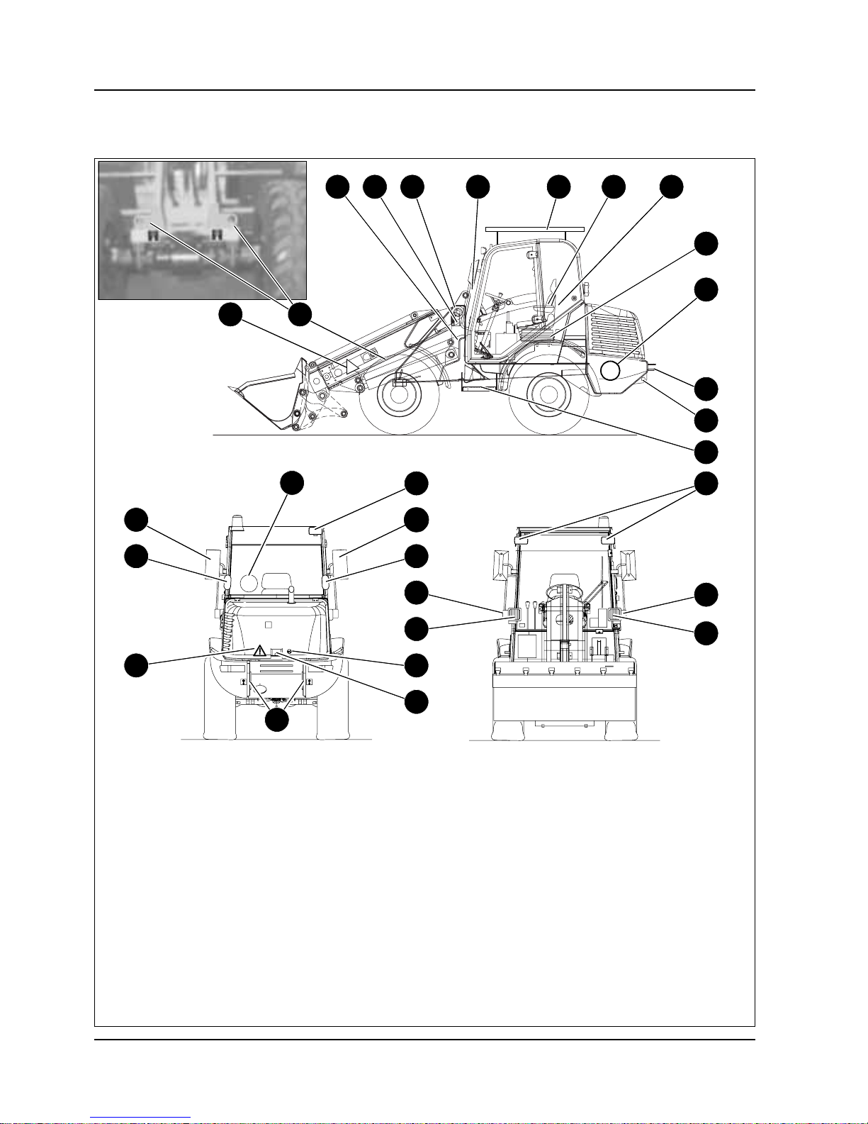
Fig.1: Machineoutside views
1 Working light (option)
2 Danger label
3 Front eye hooks – lifting and strapping down the machine
4 Wheel chock
5 Horn
6 Mark – telescopic unit position for long-haul travel
7 Access handle
8 Protective FOPS screen
9 Noise emission label
10 EC sign
11 Maximum driving speed label
12 Fuel filler inlet
13 Drawbar pin
14 Rear eye hooks – lifting and strapping down the machine
15 Step
16 Working light (option)
17 Turn indicator
18 Headlights
19 Engine cover lock
20 Label –“Do not open engine cover before engine is at a
standstill!”
Do not touch any moving or turning parts!
21 Brake light, rear light, turn indicator
22 Rearview mirror
2
20
6 8 9
4
5
10
11
13
14
21
21
2
20
11 1
16
22
17
18
17
18
7
15
19
12
22
3
20
14
!
Page 14

AP0902 1–3
Introduction
1.3 Brief description
The wheel loader model 418T is a self-propelled work machine.
Thismachine is aversatile and powerful helper for moving earth,gravel and debrison construction sites and elsewhere. The wide range of attachments accounts for the numerous
applications of the machine: as a fork lift, a snow plow, a spreader for sand, salt etc., a
sweeper or a tree replanter. See part 1.4 Applications for further applications. Fit the
machine with the respective safety devices when using it as a lifting machine (see “Applications with lifting accessories” in Part 2 Safety Instructions).
The main components of the wheel loader model 418T are:
• ROPS tested operator’s cab
• Water-cooled four cylinder PERKINS diesel engine, 58 hp (43.1 kW) at 2400 rpm (as
per DIN ISO 9249)
• Sturdy steel sheet frame in torsion-resistant box-type design
• Hydrostatic drive with electronic control, inching; 12 mph (20 km/h) max. speed
• Hydrostatic four-wheel steering with emergency steering features
• Front and rear planetary axles, rear axle with oscillation
• Service brake (mechanical or hydrostatic), mechanical disk-type parking brake
• Telescopic unit with safe load indicator
Hydrostatic drive The diesel engine drives a hydraulic pump, whose oil flow is sent to a hydraulic motor con-
nected to the rear axle. The force of the hydraulic motor is transmitted to the rear axle via
the transfer gearbox. At the same time, the front axle is driven by the cardan shaft, ensuring permanent four wheel drive.
Work hydraulics and hydro st at ic four wheel steering
Thediesel engine also drives the joint gear pump for work hydraulics and hydrostatic fourwheel steering. The oil flow of this pumpdepends on the diesel engine speed only.
Whenthe machine is in operation,the entire diesel engine outputcan be transmitted to the
gearpump forwork hydraulics and steering. Thisis madepossible by theso-called inching
whichresponds as soon as theinching brake is used, reducingor cutting off power inputof
the drive. Therefore, engine output is fully available for the telescopic unit by pressing the
accelerator pedal and the i nching brake pedal at the same time.
Cooling system A combined oil/water cooler (for the diesel engine and the hydraulic oil) is located at the
rear of the machine. The warning lights in the instrument panel 17 ensure constant monitoringof the coolant and hydraulic oil temperature. In addition, an audible signal sounds in
the machine cab as soon as there is danger of coolant or hydraulic oil overheating and in
case of low engine oil pressure.
Page 15

1–4 AP0902
Introduction
1.4 Applications
The attachments will determine where and how the machine can be used.
The following table gives an overview of the possible attachments.
Description and Model Model No. Use
Standard bucket w/ teeth
– normal material 418T
810136 Loosening, picking up, transporting and loading loose or
solid material (material density ≤ 2700 lbs/yd³ (18 kg/m³))
Pallet forks 418T 810135 Picking up and transporting pallets per load diagram
Page 16

AP0902 1–5
Introduction
1.5 Regulations
Driving license
Earth moving machinery should be driven on public roads only ifthe driver has a drivers
license.
Get informed on and follow the legal regulations of your country.
Equipment
The highway regulations of your state/province may require you to equip your machine
with:
• Slow-Moving Vehicle (SMV) emblem
• warning lights
Become informed on and follow the local highwayregulations.
Gehl will send you the original copy of this Declaration of Manufacturer at your request.
Please state name of product, model and identification number (see type label of the
attachment).
Page 17

1–6 AP0902
Introduction
1.6 Machine data
The following data provide a detailed description of your machine. Please supply your
dealer with these data for all correspondence or telephone inquiries.
Please read the data valid for your machine off the serial number plates, and enter this
data in the list. They will immediately be at hand for all inquiries or service parts orders.
Machine model: ......................................................................................................................................
Date of registration: ......................................................................................................................................
Service hours/kilometerreading: ......................................................................................................................................
Serial number: ......................................................................................................................................
Cab number: ......................................................................................................................................
Engine no.: ......................................................................................................................................
Variable displacement pump model –
identificationno.:
......................................................................................................................................
Variable displacement motor model –
identificationno.:
......................................................................................................................................
Front axle no.: ......................................................................................................................................
Rear axle no.: ......................................................................................................................................
Cab no.: ......................................................................................................................................
Optional attachments: ......................................................................................................................................
Your local dealer:
• Address:
• Telephone:
Page 18
AP0902 1–7
Introduction
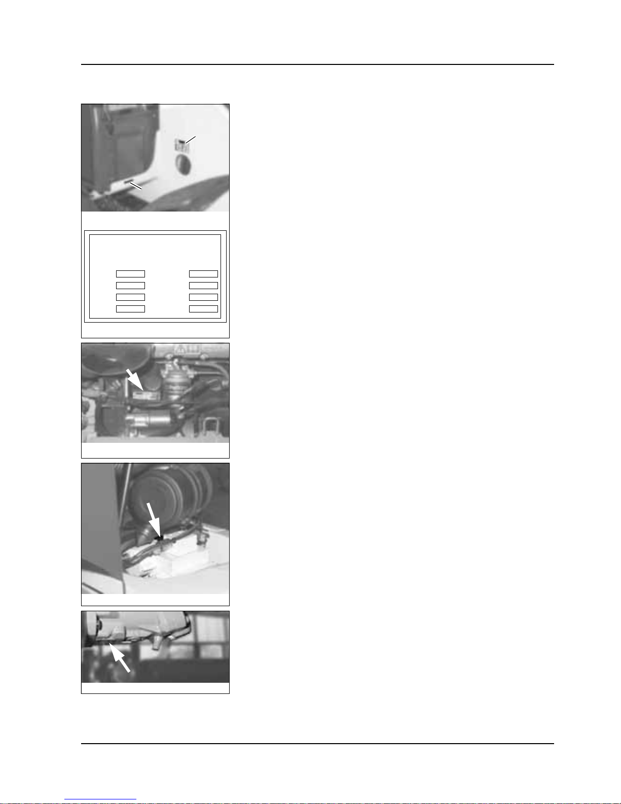
1.7 Type labels and component numbers
Type label
The type label (Fig. 3) is located at the front right of the machine frame (Fig. 2/1)
Serial number
The serial number is stamped on the machine frame (Fig. 2/2). It is also stamped on the
type label (Fig.3)
Example for wheel loader model 418T:
418T 0005
Engine number
The engine number is located on the label atthe front of the engine block (arrow, Fig. 4)
Example:
073 305
Number of hydraulic pump
The type label (arrow, Fig. 5) islocated on the pump, below the air filter
Hydraulic m otor number
Thetype label (arrow,Fig. 6) is located on the lower side of the hydraulicmotor, above the
cardan shaft
Fhzg-Typ
Model
Modèle
308
311 10
311 10 0003
2001
Typ / Ausf.
Version
Version
Fg.-Nr.
Serial no.
No. de sé rie
Baujahr
Model year
Année fabr.
Zul. Achslast vorn
Front GAWR
PNBE AV
Zul. Achslast hinten
Rear GAWR
PNBE AR
Zul. Ges. Gew.
GWR
PTAC
Leistung
Output
Performance
[ kg ]
[ kg ]
[ kg ]
[ kW ]
3750
3750
6000
43,5
31100b0230.eps
Fig.2: Type label:location
Fig.3: Type labelmodel 418T
1
2
Fig.4: Dieselengine number
Fig.5: Hydraulicpump: type label
Fig.6: Hydraulicmotor: type label
Page 19
1–8 AP0902
Introduction
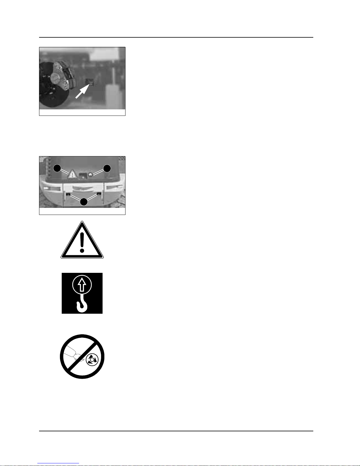
Front/rear a xle number
The axle number is located on the type label, on the right side of each axle (arrow, Fig. 7)
1.8 Safety signs and symbols
The following explains signs and symbols that do not contain explanatory text.
...on the outside of th e machine
Meaning
General indication of danger:
This sign (Fig. 9) warns persons standing or working near the machine of increased danger around the machine.
Location
Front left and right of machine frame, and at rear of machine (Fig. 8/3)
Meaning
Eye hooks/limit (Fig. 10)stops on the machine. The eye hooks are used for liftingor strapping down the machine.
Location
At the rear of the counterweight (Fig. 8/2), as well as
at the front above the front axle, left and right on the frame
Meaning
1 (Fig. 11) Do not open engine cover before engine is stopped!
2 (Fig. 11)Do not touch any movi ng or turning parts!
Location
At the rear on the engine cover (Fig. 8/1), as well as on the engine block.
Fig.7: Type labelon the front axle
Fig.8: Decalsat the rear
3
3
2
308b0360.eps
Fig.9: Dangersign
308b0680.ep
s
Fig.10: Decal: eyehooks
Fig.11: Prohibitory sign
Page 20

AP0902 1–9
Introduction
Meaning
Read and observe the operator’s manual before carrying out maintenance work!
Location
On the engine block (Fig. 12)
Fig.12: Please referto operator’smanual
Page 21
1–10 AP0902
Introduction
...inside t he operator’s compa rt ment
Meaning
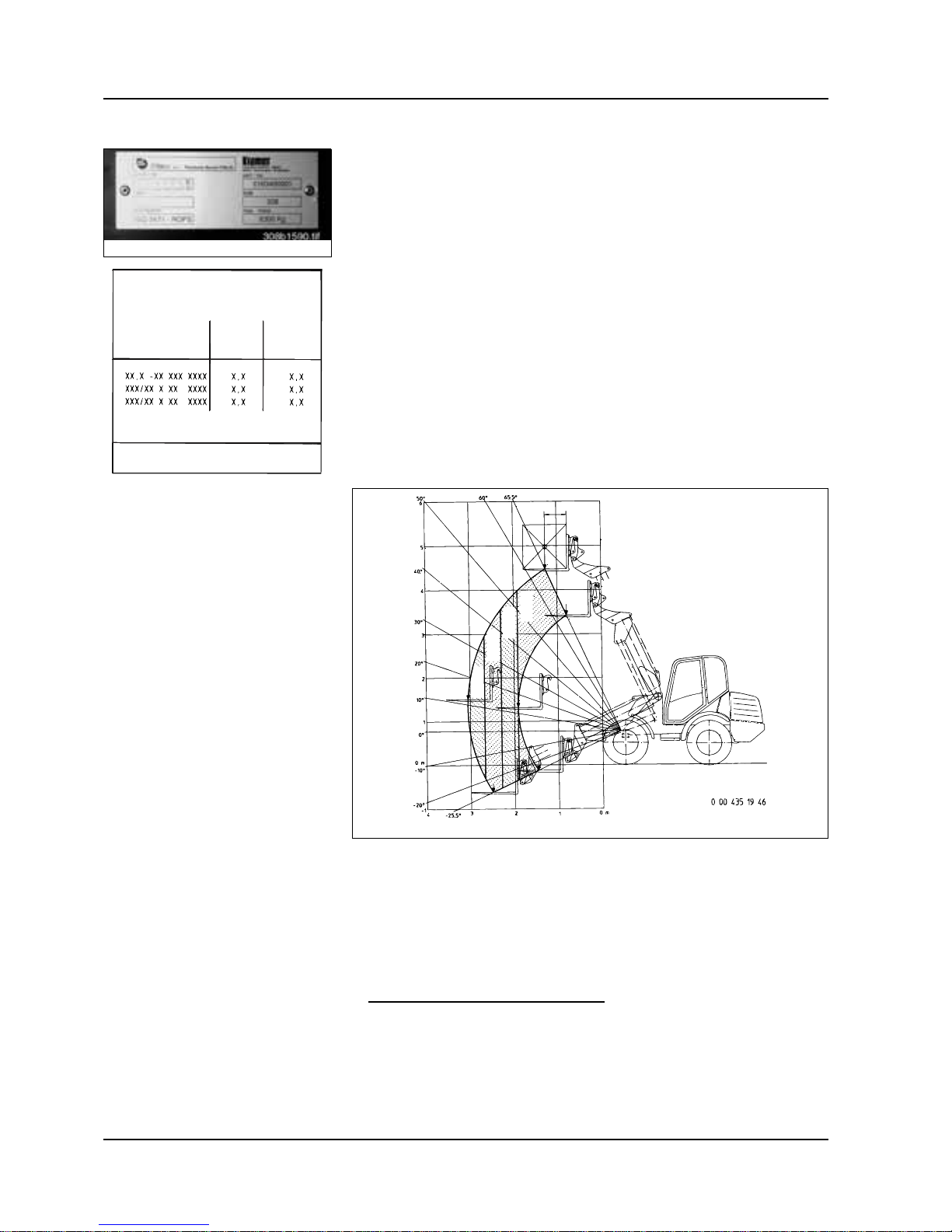
Cab type label (Fig. 13)
Location
On left side of B-column
Meaning
Tire inflation pressure table (Fig. 14)
List of authorized types of tires with prescribed tire inflation pressure
Location
Inside the cab, on left side of front window
Meaning
Load diagram (Fig. 15 for operation with pallet forks (fork arms):
The framednumbers indicate the maximum authorized load on the fork arms for industrial
(S=1.25) and off-road (S=1.67)applications respectively. The maximum load varies
accordingto the horizontal and vertical distance ofthe load center,in thediagram depicted
onthe fork armswith a distance of 500 mm to the rear of the fork arms. The telescopic unit
with fork arms moves within the dotted range.
Reading example for attachment no. 810135
:
Off-road application
➝ safetyfactor S=1.67
Distance of load to rear of fork arms = 20 inches (500 mm)
Height of fork arm above tire contact area = 61 inches (1.56 m)
Distance to tire front = 132 inches (3.36 m)
Maximum load is 2061 lbs (935 kg)!
Fig.13: Cab inspectionlabel
31100b0010.ep
s
Reifenluftdrucktabelle
Tire pressure
Reifenbezeichnung
vorn (bar)
front (bar)
AV (bar)
hinten (bar)
rear (bar)
AR (bar)
Tires
Pneumatiques
Pression pneumatiques
Bei Stapelbetrieb Luftdruck vorne um 0,5bar erhöhen!
Increase tire pressure by 0,5 bar during pallet forks operation!
Augmenter la pression pneumatique de 0,5bar en service porte-palette
!
Fig. 14: Tyre inflation pressure table model 311 00
Fig. 15: Load diagram
31100b0210.eps
S=1,25/ 1100 kg
S=1,67/ 820 kg
S=1,25/ 1270 kg
S=1,67/ 950 kg
S=1,25/ 1500 kg
S=1,67/ 1120 kg
S=1,25/ 1800 kg
S=1,67/ 1345 kg
311-00
311-10
Traglastdiagramm
Load diagram
Diagramme de charges
Gültig für Anbaugerät
Valid for attachment
Valable pour équipement
Nr. 10103-00
Nr. 10149-00
Nr. 10162-00
Nr. 10165-00
Page 22

Section 2
Safety instructions
2
Page 23

Page 24

AP0902 2–1
2
2 Safety instructions
2.1 Identification of warnings and dangers
Importantindications regarding the safety of the operating personnel and the machine are
indicated in this operator’s manual with the following terms and symbols:
DANGER!/WARNING!/CAUTION!
Failure to observe the instructions identified by this symbol may result in
personal injury or deathfor the operator or other persons.
☞Measures for avoiding danger
IMPORTANT
Failure to observe the instructions identified by this symbol may result in
damage to the machine.
☞Measures for avoiding danger for the machine
NOTE:
This symbol identifies instructions for a more efficient and economical use of the
machine.
Environment!
Failure to observe the instructions identified by this symbol may result in damage to the
environment.
The environment is in danger ifenvironmentally hazardous material (e.g. waste oil) is not
subject to proper use or disposal.
Safety instructions
Page 25

2–2 AP0902
Safety instructions
2.2 Designated uses
• The machine is intended for:
• Moving earth, gravel, coarse gravel or ballast and rubble as well as
• Working with the attachment mentioned in the present operator’s manual
Every other applicationis regarded as not designated for the use of the machine. Gehl
will not be liable for damage resulting from use other than mentioned above. The user
alone will bear the risk.
Designated use also includes observing the instructions in the operator’s manual and
observing the conditions of maintenance and service
• Observe the pertinent regulations relevant to accident prevention, other generally
acknowledged regulations regarding safety and occupational medicine, as well as the
regulations and standards relevant to motor machines and traffic. The manufacturer is
not liable for damage resulting from the failure to observe these regulations
• Thesafety of the machine canbe negatively affected by carrying out machine modifica-
tions without proper authority and by using spare parts, equipment, attachments and
optional equipment which have not been checked and approved by the manufacturer.
The manufacturer will not be liable for damage resulting from this
• The manufacturer will not be liable for personal injury and/or damage to property
caused by failure to observe the safety instructions and the operator’s manual, and by
the failure to exercise due care when:
• Handling
• Operating
• Servicing and carrying out maintenance work
• Repairing
the machine. This is also applicable in those cases in which special attention has not
been drawn to the duty to exercise due care, in the safety instructions as well as in the
operator’s and maintenance manuals (machine/engine).
Read and understand the operator’s manual before starting, servicing or repairing the
machine. Observe the safety instructions!
• The machine may not be used for transport jobs on public roads
• In applications with lifting accessories, the machine is to be used according to its desig-
nated use only if the required safety devices areinstalled and functional
Page 26

AP0902 2–3
Safety instructions
2.3 General conduct and safety instructions
Organization al measures • The machine has been designed and built in accordance with current standards and
therecognized safety regulations.Nevertheless, its use may constitute a risk to life and
limb of the user or of third parties, or cause damage to the machine and to other
material property if it is not used properly.
• The machine must only be used in mechanically good condition in accordance with its
designated use(s) and the instructions set out in the operator’s manual, and only by
safety-conscious persons who are fully aware of the risks involved in operating the
machine. Any malfunctions, especially those affecting the safety of the machine, must
therefore be corrected immediately!
Basic rule:
Before starting the machine, i nspect the machine for safety in work androad operation!
• Careful and prudent operation is the best way to avoid accidents!
• The operating instructions must always be available, and must therefore be kept in the
storage compartment provided for in the cab.
Immediately complete or replace an incomplete or illegible operator’s manual.
• In addition to the operating instructions, observe and instruct the operator in all appli-
cable legal and mandatory regulations relevant to accident prevention and environmental protection.
These compulsory regulations may also deal with the handling of hazardous
substances, issuing and/or wearing of personal protective equipment, or traffic regulations.
• With regard to specific operational features, e.g. those relevant to job organization,
work sequences or the persons doing the work, supplement the operator’s manual by
correspondinginstructions, including those relevant tosupervising and reporting duties.
• Persons who with work on the machine must have read and understood the operator’s
manual and in particular, Section 2 “Safety Instructions” before beginning work. This
applies especially to persons working only occasionally on the machine, e.g. set-up or
maintenance.
• The user/owner must check – at least from time to time – whether the persons doing
operationor maintenance ofthe machine are workingin compliance with the operator’s
manual and are aware of risks and safety factors.
• The user/owner commits himself to operate and keep the machine in a good operating
condition, and, if necessary or required by law, to require the operating or servicing
persons to wear protective clothing etc.
• In the event of safety-relevant modifications or changes on the machine or of its
behavior, stop the machine immediately and report the malfunction to the competent
authority/person.
Safety-related damage or malfunctions of the machine must be corrected immediately.
• Never make any modifications, additions or conversions to the machine and its super-
structure (cab, telescopic unit etc.), as well as to the attachments, which might affect
safety without the approval of the manuufacturer! This also applies to the i n stallation
and the adjustment of safety devices and valves, as well as to welding work on loadbearing elements.
• Service parts must comply with the technical requirements specified by the manuufac-
turer. Original service parts from the manuufacturer can be relied to do so.
• Replace hydraulic hoses within stipulated and appropriate intervals even if no safety-
related defects have been detected.
Page 27

2–4 AP0902
Safety instructions
• Before working on or withthe machine, take off jewelry, such as rings, wristwatches,
bracelets, etc., and tie back long hair, and do not wear loose-fitting garments, such as
unbuttoned or unzipped jackets, ties or scarves.
Injury may result from beingcaught up in the machinery or from rings catching on
moving parts!
• Keep the machine clean. This reduces:
• Fire hazard, e.g. due to oil-soaked rags lying around
• Danger of injury, e.g. due to dirt or debris on the steps, and
• Danger of accident e.g. due to dirt or debris on the brake or accelerator pedal!
• Observe all safety, warning and information signs and decals on the machine.
• Adhere to prescribed intervals or those specified in the operator’s manual for routine
checks/inspections and maintenance work!
• For service, inspection, maintenance or repair work, tools and workshop equipment
adapted to the task involved are absolutely indispensable.
Selection and qualification of personnel, basic responsibilities
• Any work on or with the machine must be performed by reliable personnel only. Do not
let unauthorized persons drive or work with the machine! Observe statutory minimum
age limits!
• Employ only trained or instructed staff on the machine, and set out clearly and unequiv-
ocallythe individual responsibilities of the personnel for operation, set-up,maintenance
and repair!
• Define the machine operator's responsibilities – including observing traffic regulations.
Give the operator the authority to refuse instructions by third parties that are contrary to
safety.
• Do not allow persons to be trained or instructed, or persons taking part in a general
training course, to work on or with the machine without being supervised by an experienced person!
• Work on the electrical system and equipment, on the chassis and onthe steering and
brake systems may be carried out only by skilled personnel who has been specially
trained for such work.
Work on the hydraulic system of the machine must be carried out only bypersonnel
with special knowledge and experience of hydraulic equipment!
• Seal off the area of danger should it not be possible to keep a safe distance.
Stop work if persons do not leave the area of danger in spite of w arning! Keep out of
the area of danger!
Area of danger:
Thearea of danger is the areain which persons are in dangerdue to themovements of
the
• Machine
• Work equipment
• Additional equipment, or
• Material
This also includes the area affected by falling material, equipment, or by parts that are
thrown.
Page 28

AP0902 2–5
Safety instructions
2.4 Safety instructions regarding operation
Normal operat ion • Before beginning work, familiarize yourself with the surroundings and circumstances of
the work site. These are, e.g., obstacles in the working and travelling area, the soil
bearingcapacity and any necessarybarriers separating the work site from publicroads.
• Takethe necessary precautionsto ensure thatthe machine isused only when in a safe
and reliable condition!
• Operate the machine only if all protective and safety-related devices, e.g., removable
safety-devices, soundproofing elements and mufflers etc., are in place and fully
functional!
• Check the machine at least once daily/per working shift for visible damage and defects.
Report any changes (such aschanges in the machine’s working behavior) to the
competent organization/person immediately! If necessary, stop the machine immediately and lock it!
• In the event of malfunctions, stop the machine immediately and lock it! Have any
defects corrected immediately!
• Start and operate the machine from theoperator’s seat only!
• Carryout start-upand shut-down procedures in accordancewith theoperator’s manual,
and observe the warning lights!
• Before putting the machine/attachment into operation (start-up/moving), make sure
nobody is at risk!
• Before driving the machine, and also after stopping work, check whether the brakes,
steering, signalling and light systems are functional!
• Before moving the machine always check whether the supplementary equipment and
the attachments have been safely stowed away or attached!
• When driving on public roads, observe the traffic regulations and, if necessary, make
sure beforehand that the machine is in compliance w ith these regulations!
• In conditions of poor visibility and after dark always switch on the lights!
• No lifting, lowering or carrying of persons in the
work equipment/attachments!
• No mounting of a man basket or personal work platform!
• When crossing underpasses, bridges and tunnels, or when passing under overhead
lines, always make sure there is sufficient clearance!
• Always keep at a safe distance from the edges of excavations and slopes!
• When working in buildings or in enclosed areas, look out for the
• Height of the ceiling/clearances
• Width of the entrances and
• Maximum load of ceilings and floors
Provide for sufficient room ventilation – danger of poisoning!
Page 29

2–6 AP0902
Safety instructions
• Avoid any operation that might be a risk to stability!
• During operation on slopes, drive or work uphill or downhill. If driving across a slope
cannot be avoided, bear in mind the stability limit of the machine!
Always keep the attachments/work tool close to the ground. This also applies when
driving downhill!
When driving or working across a slope, the load must be on the uphill side of the
machine.
• On sloping terrain always adapt your driving speed to the prevailing ground conditions.
Never change to a lower gear on a slope, but always before reaching it!
• Before leaving the machine
• Lower the work tool/attachments to the ground
• Before leaving the operator seat, always secure the machine against inadvertent
movement and unauthorized use!
• Before starting work, check whether
• All safety devices are properly installed and functional
• Slow Moving Vehicle (SMV) emblem installed as needed
• Warning lights installed as needed, and
• A First-aid kit is on hand
• Before moving the machine or before starting work:
• Make sure visibility is sufficient (do not forget rearview mirrors!)
• Adjust correct seat position (brake pedal must be depressed to the limit).
Never adjust the operator seat when driving or working!
• Fasten your seat belt
• Inspect the immediate area (children!). In the work area the operator is responsible
for third parties!
• Caution when handling fuel – increased danger of fire!
Make sure fuel does not come into contact with hot parts!Stop the engine during refuelling! Do not smoke during refuelling, and avoid fire and sparks!
• Never get on or off a moving machine! Never jump off the machine!
• If the lights of the machine are not sufficient for the safe execution of certain work
processes, provide additional lighting of the work area.
• Installed rear work lights must not be switched on for travel on public roads. They can
be switched on in work operation if users of public roads are not dazzled.
• Hydrostatic four-wheel steering takestime getting used to. Therefore, adjustthe driving
speed to your abilities and the circumstances. Selection and change steering mode of
machine at standstill only!
WARNING!
Exposure to crystalline silica (found in sand, soil and rocks) has been
associated with silicosis, a debilitating and often fatal lung disease. A
Hazard Review (Pub. No. 2002-129) by the U.S. National Institute for
Occupational Safety and Health (NIOSH) indicates a significant risk (at
least 1 in 100) of chronic silicosis for workers exposed to inhaled crystalline silica over a working lifetime. NIOSH recommends an exposure limit
of 0.05 mg/m
3
as a time-weighted average for up to a 10-hr workday during a 40-hr workweek. NIOSH also recommends substituting less hazardous materials when feasible, using respiratory protection, and regular
medical examinations for exposed workers.
Page 30

AP0902 2–7
Safety instructions
Applicationswith lifting accessories Definition:
Applications with lifting accessories are understood as procedures involving the lifting,
transporting and lowering of loads with help of slings and load-securing devices (e.g.
ropes, chains). In doing so, the help of persons is necessary for securingand detaching
the load. This applies, for example, to lifting and lowering of pipes, shaft rings or containers.
• Themachine may beused for applicationswith lifting accessories onlyif the prescribed
safety devices are in place and functional.
These are, e.g.:
• Accessories for slinging and securing a lifting attachment (load hook)
• Load diagrams
• The load must be secured so as to prevent it from falling or slipping.
• Persons guiding the load or securing it must stay in visual contact with the machine
operator.
• Themachine operatormust guidethe load as near aspossible tothe ground,and avoid
any oscillating or swinging movements.
• The machine may be moved with a raised load only if the path of the machine is level.
• The persons attaching or securing loads may approach the boom from the side only,
and only after the machine operator has given permission. The machine operator may
give his permission only after the machine is at a standstill and the tool/attachment is
not moving.
• Do not use any damaged lifting attachments or such lifting accessories (ropes, chains)
that are not sufficiently sized. Always wear protective gloves when working with lifting
accessories.
Page 31

2–8 AP0902
Safety instructions
Trailers and attachments • It is not permitted to use a trailer withthe towing device of the machine!
• Attachments and counterweights affect handling, as well as the steering and brake
capability of the machine!
• Fit the attachments with the specially required devices only!
• Before uncoupling or coupling hydraulic lines (hydraulic quick couplers):
• Turn off the engine, and
• Relieve the oil pressure in the hydraulic system by moving the control levers of the
hydraulic control units backand forth a couple times.
• Coupling of attachments requires special care!
• Secure the attachments against inadvertent movement!
• Operate the machine only if all safety devices are installed and are functional, and if all
brake, light and hydraulic connections are connected!
• If optional equipment is installed, all additionally required light installations, warning
lights, etc., must be provided for and functional.
• Mount the attachments only if the engine is stopped and the drive system is switched
off.
• Relievepressure in the hydraulic system before connecting or disconnecting hydraulic
lines.
• Especially when driving or working with machines with a quick hitch facility for the
attachments, be sure that the attachment is securely locked in the quick hitch facility.
The lock pin must be visible on both sides of the bores on the attachment. Check
before starting work.
• Prior to connecting attachments to the loader, secure the control lever of the hydraulic
control against unintentional movement.
• Be careful when connecting attachments to the loadert: because of the danger of
personal injury due to crushing and shearing. Be sure nobody is between the machine
and the equipment without securing the machine and the attachment against
movement.
Transport
• The machine must be towed, loaded and transported only in accordance with the
operator’s manual!
• For towing the machine observe the prescribed transport position, speed and
procedure.
• Use only appropriate means of transport, and use lifting gear of adequate capacity!
• Safelysecure the machineon the transport machine! Use suitable mountingpoints and
load-securing devices.
• The start up procedure must be strictly in accordance with the operator’s manual!
Page 32

AP0902 2–9
Safety instructions
2.5 Safety instructions for service and maintenance
• Avoid any unsafe operational mode!
• Observe the adjusting, maintenance and inspection activities and service intervals set
out in the operator’s manual, including information on the replacement of parts/partial
equipment.
These activities may be performed by skilled personnel only.
• The machine may not be serviced, repaired or test-driven by unauthorized personnel.
• Informoperatingpersonnel beforebeginning specialoperations andmaintenance work!
Appoint a person to supervise the activities!
• In any work concerning the operation, conversion or adjustment of the machine and its
safety devices, or any work related to maintenance, inspection and repair, observe the
start-up and shut-down procedures set out in the operator’s manual, and the information on maintenance work.
• If required, secure the maintenance area appropriately!
• Prior to performing service, maintenance and repair work, attach a warning label, such
as “Repair work – do not start machine!”, to the ignition lock/steering wheel or to the
control elements.
Remove the ignition key!
• Perform service, maintenance and repair work only if:
• machine is positioned on firm and level ground
• Transmission control lever is in neutral position
• Parking brake is applied
• All hydraulically movable attachments and working equipment have been lowered to
the ground
• Engine is stopped
• Ignition key is removed, and
• machine has been secured against unintentional movement
• If maintenance or repair is required with the engine running:
• Only work in groups of two
• Both persons must be authorized to operate the machine
• One person must be seated on the operator seat and maintain visual contactwith the
other person
• Observe the specific safety instructions in the respective work manual
• Keep a safe distance from all rotating and moving parts, e.g. fan blades, V-belt
drives, PTO shaft drives, fans, etc.
• Prior to performing assembly work on the machine, be sure no movable parts will roll
away or start moving.
• To avoid the risk of accidents, individual parts and large assemblies being moved for
replacement purposes must be carefully attached and securedto lifting tackle.
Use only suitable lifting gear and suspension systems in a good condition with
adequate lifting capacity!
Never work or stand under suspended loads!
Page 33

2–10 AP0902
Safety instructions
• Thefastening of loadsand the instructing of lift operators must bedone by experienced
persons only!
The person giving the instructions to the operator must be within sight or sound of him.
• For overhead assembly work, always use specially designed or otherwise safety-
oriented ladders and work platforms.
Never use machine parts or attachments/superstructures as a climbing aid!
Wear a safety harness when carrying out maintenance work at greater heights!
Keep all handles, steps, handrails, platforms, landings and ladders free from dirt, snow
and ice!
• Clean the machine, especially connections and threaded unions, of any traces of oil,
fuel or preservatives before carrying out maintenance/repair work!
Do not use aggressive detergents!
Use lint-free cleaning rags!
• Before cleaning the machine with water, steam cleaning (high-pressure cleaning) or
using detergents, cover or tape up all openings that– for safetyand functional reasons
– must be protected against water, steam or detergents. Special care must be taken
with the electrical system.
• After cleaning, remove all coversand tapes applied for that purpose!
• After cleaning, examine all fuel, lubricant and hydraulic oil lines for leaks, chafe marks
and damage!
Any defects found must be corrected without delay!
• Tighten any screw connections that have been loosened during maintenance and
repair!
• Any safety devices removed for set-up, maintenance or repair purposes must be
refitted and checked upon completion of the maintenance and repair work.
• Ensure that all fluids and replaced parts are d isposed of safely and with minimum
environmental impact!
• Do not use the work tools as lifting platforms for persons!
• Before working on a machine parts/attachments move and cause injury (bruising,
cutting), always ensure safe blocking/support of these components.
• Perform maintenance and repair work beneath a raised machine, work tool/attach-
ments or additional equipment only if a safe and secure support has been provided
(Theuse of hydraulic cylinders, jacks, etc. doesnot sufficiently secure raised machines
or equipment/attachments).
• Avoidcontact with hotparts, such as the engine block or the exhaust systemduring the
operation of the machine and for some time afterwards – danger of burns!
• Retainer pins can fly out or splinter when struck with force – be careful to avoid
personal injury!
• Do not use starting fluid (ether)! This especially applies to those cases in which a
heater plug (intake-air preheating) is used at the same time – because of the danger of
explosions!
• Use special care when working on the fuel system – because of the increased danger
of fire!
Page 34

AP0902 2–11
Safety instructions
2.6 Warning of special hazards
Electricalhazards • Use only original fuses with the specified current rating!
Turn off the machine immediately and correct the malfunction if trouble occurs in the
electrical system!
• When working with the machine, maintain a safe distance from overhead electric lines!
If work is to be carriedout close to overhead lines, the equipment/attachments must be
kept well away from them. Learn the prescribed safety distances!
• If your machine comes into contact with an electrical wire:
• Do not leave the machine
• Drive the machine out of the area of danger, if possible
• Warn others against approaching and touching the machine
• Have the electrified wire de-energized
• Do not leave the machine until the electrified wire has been safely de-energized!
• Work on the electrical system may only be performed by a skilled technician, in accor-
dance with the applicable electrical system repair procedures.
• Inspect and check the electrical system of the machine at regular intervals. Defects
such as loose connections or burned cables must be corrected immediately.
• Observe the operating voltage of the machine!
• Alwaysremove theground strapfrom thebattery whenworking onthe electricalsystem
or when performing welding work!
• Starting with a battery jump cable can be dangerous if performed improperly. Observe
the safety instructions regarding the battery!
Gas, dust, steam, smok e
• Operate the machine only in adequately ventilated locations! Before starting internal
combustion engines in enclosed locations, make sure that there is sufficient ventilation!
• Carry out welding, flame-cutting and grinding work on the machine only if it has been
expressly authorized, because there may be a risk of explosion or fire.
• Beforecarrying out welding, flame-cutting and grinding work,clean the machine and its
surroundings from dust and other flammable substances, and be sure that the
premises are adequately ventilated – because of the danger of explosions!
Page 35

2–12 AP0902
Safety instructions
Hydraulic equipm ent • Work on the hydraulic equipment of the machine may be done only bypersons having
knowledge and experience in hydraulic systems!
• Check all lines, hoses and connections regularly for leaks and damage! Repair any
damage and leaks immediately! Leaking oil may cause injury and fire.
• In accordance with the operator’s manual/instructions for theassembly, relieve the
pressure in all system sections and pressure pipes (hydraulic system, ) tobe opened
before doing any repair work!
• Hydraulic lines must be routed and fitted properly. Ensure that no connections are inter-
changed. The fittings, lengths and quality of the hoses must comply with the design
specifications.
Noise
• Wear hearing protection if necessary!
Oil, grease and other chemical substances
• When handling oil, grease and other chemical substances (e.g., battery electrolyte —
sulfuricacid), observethe product-relatedsafety regulations(material safetydata sheet
MSDS)!
• Be careful when handling fluids, because of the risk of burning or scalding!
Battery When handling the battery, observe the specific safety instructions to avoid injury. Batter-
ies contain sulfuric acid.
• Especially when charging batteries, as well as during normal operation, a hydrogen-air
mixture is formed in the cells which has a danger of explosion!
• In the case of a frozen battery or of an insufficient electrolyte level, do not try start-up
with jumper cables. The battery can burst or explode.
Tires
• Repair work on tires and rims may be carried out by skill ed personal or by an autho-
rized workshop only!
• Damaged tires and/or wrong tire pressure reduce the operational safety of the
machine. Therefore conduct regular checks of the ti res for
• Prescribed tire pressure and
• Damage
• Do not inflate tires with inflammable gas – danger of explosion!
• Conduct regular checks of the wheel nuts for tightness, at least every 600 service
hours. After changing tires check thewheel nuts after 10 service hours – tighten if
necessary!
Page 36

Section 3
Operation
Page 37

Page 38

AP0902 3-1
3
3 Operation
This chapter describing the controls contains information on the function and the use of the individual warning lights and controls in the
operator cab.
The pages listed in the table refer to the description ofthe corresponding controls.
The identification of the controls with a combination of digits or a combination of digits and letters, e.g. 40/18 or 40/A, means: Figure no.
40/control element no. 18 or position A in figure no. 40.
A figure carries no number when it is placed to the left of the text.
Unfold pages 3-2 and 3-4 for a better overview.
The symbols used in the description have the following meanings:
• This symbol stands for a list
• This symbol stands for the subdivision of an enumeration or an activity. Follow the steps in the recommended sequence
☞This symbol requiresyou to carry out the activity described
➥Description of the effects or results of an activity
n. s. = not shown
SO = option
Stated whenever controls or other components of the machine are installed as an option.
Overview: see overleaf
Page 39

31110b0062.eps
308b0950.eps
308b0960.eps
Operation
3-2 AP0902
1 2 3
19
21
22
6
8 9
10
25
7
Fig.16: Cab: overview
3.1 Overview of cab
Ref. no.
Description For more information see page
1 Door lock..................................................................................................................................................................................................3-35
2 Washer fluid tank.....................................................................................................................................................................................3-30
3 Brake inching pedal ...................................................................................................................................................................................3-9
4 Brake fluid tank....................................................................................................................................................................... 3-6, 5-27, 5-39
5 Hydrostatic steering................................................................................................................................................................................. 3-21
6 Accelerator pedal.......................................................................................................................................................................................3-9
7 Multifunctional lever...........................................................................................................................................................................3-4,3-11
8 Sun visor
9 Interior light..............................................................................................................................................................................................3-27
10 Rearwiper – rocker switch ......................................................................................................................................................................3-30
11 Hook
12 Doorholder left and right.........................................................................................................................................................................3-35
13 Driveelectronics.......................................................................................................................................................................................3-9,
14 Electronicload indicator...........................................................................................................................................................................3-43
15 Frontwiper...............................................................................................................................................................................................3-30
16 Sidewindow, locking ...............................................................................................................................................................................3-35
17 Controlpanel....................................................................................................................................................................................3-4, 3-13
18 Heatercontrol..........................................................................................................................................................................................3-29
19 Controlflap for fan................................................................................................................................................................................... 3-29
20 Cabtype label............................................................................................................................................................................................1-7
21 Controllever – telescopic.................................................................................................................................................................3-4, 3-45
22 Controllever – 3rdcontrol circuit/ attachment .........................................................................................................................................3-46
23 Lockfor control lever 22 ..........................................................................................................................................................................3-45
24 Sideconsole ..............................................................................................................................................................................................3-4
25 Parkingbrake...........................................................................................................................................................................................3-10
26 Smallstorage compartment
27 Largestorage compartment
28 Operator'sseat ........................................................................................................................................................................................3-31
29 Seatbelt...................................................................................................................................................................................................3-33
30 Toolkit
4 5
17
18
20
23
11
16
24
26
27
30
12
13
15
28
14
29
Page 40

AP0902 3-3
Overview: see overleaf Overview: see overleaf
Page 41

Operation
3-4 AP0902
30864b0091.eps
30864b0060.eps
7
31
33
34
35 36 37 38 39
40 41 42 43
44
46
45
Fig. 17: Multifunctional lever
Fig. 18: Control lever Fig.19: Control panel
Fig. 20: Side console
3.2 Overview:Multifunctional lever and consoles
Ref. no.
Description
Page
Multifunctional lever
31 Lever– turn indicator, high beam, headlight flasher............................................................................................................. 3-11, 3-27, 3-28
32 Rotaryswitch – lights (parking light and lowbeam)........................................................................................................................3-11, 3-27
33 Tipswitch – washer pump..............................................................................................................................................................3-11, 3-30
34 Tipswitch – horn.............................................................................................................................................................................3-11, 3-28
Control panel
35 WarningLight (red) – alternator charge function.....................................................................................................................................3-13
36 WarningLight (red) – coolant temperature ..............................................................................................................................................3-13
37 WarningLight (yellow) – air filter .............................................................................................................................................................3-14
38 WarningLight (red) – hydraulic oil temperature.......................................................................................................................................3-14
39 WarningLight (red) – hydraulic oil filter...................................................................................................................................................3-14
40 WarningLight (red) – engine oil pressure................................................................................................................................................3-14
41 WarningLight (red) – parking brake ........................................................................................................................................................3-14
42 WarningLight (green) – right/left turn indicator .......................................................................................................................................3-15
43 WarningLight (blue) – high beam............................................................................................................................................................3-15
44 Notassigned
45 Hourmeter...............................................................................................................................................................................................3-15
46 Fuellevel gauge ......................................................................................................................................................................................3-15
47 Rockerswitch – rotating beacon (option) ................................................................................................................................................ 3-28
48 Rockerswitch – electrically operated attachments (option).....................................................................................................................3-49
49 Notassigned
Side console
50 Fuseboxes A, B and C..............................................................................................................................................................................7-5
51 Socket/cigarettelighter ..............................................................................................................................................................................7-5
52 Preheatingstart switch .....................................................................................................................................................................3-8, 3-16
53 Rockerswitch – hazard warning system .................................................................................................................................................3-28
54 Tipswitch – lock for quickhitch facility.....................................................................................................................................................3-50
55 Rockerswitch – front wiper......................................................................................................................................................................3-30
56 Rockerswitch – fan .................................................................................................................................................................................3-29
57 Rockerswitch – front and rear working lights (option).............................................................................................................................3-27
58 Rockerswitch – drive range ....................................................................................................................................................................3-23
Telescopic unit: control lever
59 Tipswitch (green) – forward travel ...................................................................................................................................................3-8, 3-24
60 Tipswitch (yellow) – reverse travel...................................................................................................................................................3-8, 3-24
61 LED(green) – forward travel ............................................................................................................................................................3-8, 3-24
62 LED(yellow) – reverse travel............................................................................................................................................................3-8, 3-24
63 Tipswitch – extend telescopic unit ..........................................................................................................................................................3-53
64 Tipswitch – retract telescopic unit...........................................................................................................................................................3-53
32
51
52
17
24
63
21
22
23
59
6460
61
62
4847 49
53 55
56 57
54
50
58
A B C
Page 42

AP0902 3–5
Operation
3
3.3 Placing into service
3.3.1 Safety instructions
•
Only use the steps and handles provided when entering and leaving the cab
• Never use the controls or movable lines and cables as handles
• Never jump on or off a moving machine
• Refer to the corresponding load diagrams for the loader unit pallet forks
3.3.2 Placing the machine into ser vice for the first time
Importantinformation • The machine may be placed into service by authorized personnel only
• Theoperating personnel must have read and understood this operator’s manual before
placing the machine into service
• Themachine may only be usedin good conditionin accordance withits designated use
and the instructions set out in the operator’s manual, and only by personswho are fully
aware of the risks involved in operating the machine
• Go through the “Start-up” checklist in the following section
Running-in pe ri od Operatethe machine carefully during its first 100 operating hours.
The future performance and service life of the machine are heavily dependent on the
observance of the following recommendations during the running-in period.
• Donot overload the machine, butat the sametime do notdrive too cautiously either, as
the machine will never reach the proper operating temperature
• Do not run the engine at high speeds for extended periods
• Increase the load gradually while varying the engine speed
• Strictly observe the maintenance schedules in the Annex
Operation
Page 43

3–6 AP0902
Operation
3.3.3 Checklists
The check lists below are intended to assist you in checking and monitoring the machine
before, during and after operation.
These check lists cannot claim to be exhaustive; they are merely intended as an aid for
you in fulfilling your duties as a conscientious operator.
The checking and monitoring jobs listed below are described in greater detail in subsequent sections.
If the answer to one of the following questions is NO, first rectify the cause of the fault
before commencing or continuing work.
Start-up c heck li st Check the following points before taking the machine into service or starting the engine:
No. Question ✔
1 Sufficient fuel in the tank? (➠ 5-1)
2 Coolantlevel OK? (➠ 5-10)
3 Engineoil level in order? (➠ 5-7)
4 Oillevel in hydraulic oil tank in order? (➠ 5-16)
5 Brakefluid level OK? (➠ 5-27)
6 Waterlevel in windscreen washer tank in order? (➠ 3-30)
7 Telescopiclinkage lubricated? (➠ 5-28)
8 Tirecondition OK? (➠ 5-30)
9 Lights,signals, indicators, and warning lights OK?
(➠ 3-27, 3-28, 3-13)
10 Windows, mirrors, lights and steps clean?
11 Is the attachment on the telescopic correctly connected? (➠ 3-48)
12 Is the engine cover firmly locked? (➠ 3-38)
13 Especially after cleaning, maintenance or repair work:
Rags, tools and other loose objects removed?
14 Approved SMV emblem, hazard warning lights in the machine? (➠ 1-5)
15 Seat position and rearview mirror correctly adjusted? (➠ 3-16)
16 Seat belt fastened? (➠ 3-33)
Page 44

AP0902 3–7
Operation
Operation checklist After starting the engine and during operation, check and observe the following points:
Parking checklist Check and observe the following points when parking the machine:
No. Question ✔
1 WarningLights for engine oil pressure, coolant level and alternator gone out?
(➠ 3-13)
2 Brakingeffect sufficient? (➠ 3-21)
3 Temperatureindicator for engine coolant in normal range? (➠ 3-13)
4 Isthe steering working properly? (➠ 3-21)
5 Isanyone dangerously close to the machine? (➠ 2-7)
6 Safeload indicator tested and OK? (➠ 3-44)
When travelling on public roads, particular attention should be paid to the
following points:
7 Telescopicunit completely retracted? (➠ 3-53)
8 Bucketand attachments in transport position? (➠ 3-20)
9 Transportlocks installed? (➠ 3-20)
10 Control lever for lift and tilt hydraulics of the telescopic locked? (➠ 3-20)
No. Question ✔
1 Attachmentson the telescopic unit lowered to the ground? (➠ 3-26,3-45)
2 Parkingbrake applied? (➠ 3-10)
3 Machine cab locked (especially if the machine cannot be supervised)? (➠
3-35)
When parking on public roads:
4 Machineadequately secured? (➠ 3-26)
When parking on uphill and downhill gradients:
5 Machine additionally secured with chocks underthe wheels to prevent it from
rolling away? (➠ 3-26)
Page 45

3–8 AP0902
Operation
3.4 Driving the machine
3.4.1 Overview of controls:
Preheating start switch [52]
NOTE:
The engine will start only if parking brake 16/25 is applied.
Driving di re ct io n selector switc h Function
• Selection of driving direction/neutral position of drive
☞ Selection of driving direction/neutral position:
NOTE:
The joystick is in neutral when you start the engine. Neutral is selected when you
apply the parking brake or turn off the engine. Driving direction can be selected
only after releasing the parking brake!
1
0
2
3
52
Fig.21: Preheating start switch
P
Position Function Power consumer
P No function None
0 Inserting or removing ignition key None
1 ON/drive position
➥ All functions are operational
➥ Warning Light 19/41 comes on if
parking brake 16/25 is applied
2 Preheating engine (with cold starting at < 0 °C: 10 – 15 seconds)
3 Start the engine
➥ Starter is actuated
➥ Warning Lights must go out
21
59
Fig.22: Driving directionselector switch
60
61
62
Function Operation Effect
• Forward ☞ Press green tip switch 59 ➥ Green LED 61 comes on
• Reverse ☞ Press yellow tip switch 60 ➥ Yellow LED62 comes on
• Neutral position ☞ Pressboth tip switchesat the
same time
➥ Both LEDs go out
Page 46

AP0902 3–9
Operation
Drive range selector [58] Function
• Selection of drive range with rocker switch 58
Accelerator pedal [6]
The accelerator pedal 6 controls the drive speed as follows:
Brake inc hi ng pedal [3] Function
• To brake the machine irrespective of the braking effect of the drive and the position of
the accelerator pedal 6
• Inthe inching range of the brake pedal(pedal pressed inlightly), the pedal can be used
like a car’s clutch. Thedrive system is supplied with less hydraulic oil, which means the
entire engine output is available to the work hydraulics. This allows the loader to raise
more rapidly
Braking
☞ Press the brake inching pedal 3 down with force
Inching
☞ Press the brake inching pedal 3 down lightly
Fig.23: Drive rangeswitch
58
B
A
Drive range Rocker switch 58 Recommended for:
• Low
0–3mph
(0–5km/h)
☞ Press rocker switch 58 in A
(below)
Heavy work
• High
0–12mph
(0–20km/h)
☞ Press rocker switch 58 in B
(above)
Long-haul transport, road
travel
Fig.24: Acceleratorpedal
6
• Press pedal ➥ Drive speed is increased
• Release pedal slowly ➥Drive speed is reduced
• Release pedal fully ➥ Hydrostatic braking
Fig.25: Brake inchingpedal
3
Page 47

3–10 AP0902
Operation
Parking brake [25] Function
NOTE:
A driving interlock prevents the machine from driving with the parking brake
applied.
The forward/reverse driving direction can be selected via tip switches 1859/ and
18/60 and only if the parking brake is released. Applying the parking brake automatically interrupts forward/reverse driving direction, which is set to neutral (LEDs
on joystick goes out).
• Prevents the machine rolling away
• Emergency brake in case of service brake breakdown
WARNING!
Use the parking brake 25 instead of the service brake only in an emergency ,
i.e. in case of a breakdown of the service brake. The brake lights do not light
up, and the machine stops abruptly, which can be hazardous
☞In normal operation, only use brake inching pedal 16/3 as a service brake
To preven t the machine rolling away
☞ Pull up lever 25 to the last notch
➥ Warning Light 19/41 comes on
To release the parking brake
☞ Pull up lever 25 slightly
☞ Depress button a
☞ Move lever 25 all the way down
25
Fig.26: Parking brake
25
Fig.27: Applying and releasingthe parking brake
a
Page 48

AP0902 3–11
Operation
To use the parking brake as emergency brake when driving the mac hi ne
WARNING!
Operating the parking brake 25 when driving causes the machine drive to
disengage. This causes sudden deceleration at full speed, which can be
hazardous.
☞Use the parking brake 25 as service brake only in case of emergency
☞Before using the parking brake 25 reduce driving speed if possible
☞ Pull up lever 25
Multifunctional lever [7] Function
• Switch on the turn indicators with lever 31
• Switch high beam on and off with lever 31
• Flash headlight flasher with lever 31
• Switch lights (parking light and low beam) on and off with rotary switch 32
• Switch on front window washer pump with tip switch 33
• Sound horn with tip switch 34
Switches on h ig h beam and h ea dli gh t flasher with lever 31
Turn indication with lever 31
31
7
32 33
Fig.28: Multifunctionallever
34
7
Fig.29: Switching on highbeam and headlight flasher
31
I
I
0
I
Lever 31 Effect
☞Central position 0 ➥ High beam and headlight flasher OFF
➥ Low beam ON
☞Lower position I ➥High beam ON if low beam is switched
on with rotary switch 32. Warning Light
43 comes on
☞Raise to position II and hold in this
position
➥ Headlight flasher ON, warning light 43
comes on
Fig.30: Turnindicators
31
L
R
Lever 31 Effect
☞Pull upward ➥ Left turn indicators actuated, warning
light 42 flashes
☞In center position ➥ None
☞Pull backward ➥ Right turn indicators actuated, warning
light 42 flashes
Page 49

3–12 AP0902
Operation
Actuate w a sher pump with tip switch 33
Soundhornwithtipswitch34
Fig.31: Actuatingthewasher pump
33
Tip switch 33 Effect
☞Slide to the left and hold ➥ Washer pump ON
☞Release ➥Washer pump OFF
Fig.32: Actuatingthehorn
34
Tip switch 34 Effect
☞Press ➥ Horn ON
☞Release ➥Horn OFF
Page 50

AP0902 3–13
Operation
3.4.2 Warning Lights: overview
Unfold page 3-4 for a better overview!
35 Warnin g Light (red) – alternator charge function
The warning light comes on when the ignition is turned on and goes out as soon as the
engine is running.
The V-belt for the alternator, or the charging circuit of the alternator is faulty if the warning
light comes on with the engine running. The battery is not charged any more (➠ page
5-15.
Important!Important!
The coolant pump no longer runs if the V-belt is faulty.
Possibility of engine overheating or breakdown!
If warning light 1935 comes on with the engine running:
☞Switch off the engine immediately and repair or have the cause repaired
36 Warning Light (red) – coolant temperature
Comes on if coolant temperature is too high. A buzzersounds at the same time. The warning light and the buzzer go out as soon as the coolant temperature is back in the acceptable range.
WARNING!
Never open the coolant tank and never drain coolant if the engine is warm,
because the cooling system is under high pressure –
Danger of burns!
☞
Wait at least 10 minutes after turning off the engine!
☞Wear protective gloves and clothing
☞Always start by actuating the safety valve in the cap of the expansion tank.
To do this: Turn the cap to the first notch and allow the pressure to escape
Important!Important!
Possibility of engine breakdown if warning light 19/36 comesonwiththe
engine running!
☞After extreme work load:
Let the engine run at idle until the warning light goes out
☞After normal workload or if the warning light does not go out as described
above:
Turn off the engine immediately
☞Check and correct the coolant level (➠ page5-10)
Page 51

3–14 AP0902
Operation
37 Warning Light (yellow) – air filter
Indicates air filter contamination. In this case:
☞ Clean or replace the air filter (➠ page5-13)
38 Warning Light (red) – hydraulic oil tem pera tur e
Comes on if hydraulic oil temperature is too high.
Important!Important!
Possibility of hydraulic damage as soon as warning light 19/38 comes on!
☞Reduce the load on the work and drive hydraulics. To do this:
• Stop the machine in a suitable place
• Move control lever 16/21 of the loader to neutral position
• Set drive switch to neutral – see Driving direction selector switch on
page 3-8
• Run the engine at increased speeds until warning light 19/38 goes out
39 Warning Light (red) – hydraulic oil fil ter
Indicates an unacceptably high pressure in the hydraulic return line to the tank. In this
case:
☞ Replace the hydraulic oil return filter (➠ page5-20)
In cold weather warning light 19/ 39 may come on immediately when the engine is started.
This is due to increased oil viscosity. In this case:
☞ Let the engine run at idling speed for about 2 minutes
40 Warning Light (red) – engine oil pressu re
Comes on if the engine oil pressure is too low. In this case:
☞ Stop the machine
☞ Turn off the engine immediately and check the oil level (➠ page5-7)
The warning light comes on when the ignition is turned on and goes out as soon as the
engine is running.
41 Warning Light (red) – parking brake
Comes on when parking brake lever 16/25 is applied.
The electric driving interlock prevents driving the machine with the parking brake applied.
P
Page 52

AP0902 3–15
Operation
42 Warnin g Light (green) – right/left turn indicator
Flashes intermittently when the turn indicators are used (lever 17/31)
43 Warning Light (blue) – high beam
Comes on if high beam is switched on, or during headlight flashing
44 Not a ss igne d
45 Hourmeter
Counts the engine service hours with the engine running
46 Fuel level gauge
Page 53

3–16 AP0902
Operation
3
3.4.3 Before starting the engine
1
☞ Run through the “Start-up” checklist on page 3-6
☞ Adjust seat position and rearview mirror
CAUTION!
All controls must be within easy reach. You must be able to move the brake and
accelerator pedals to their limit positions!
☞ Fastening the seat belt
☞ Be sure that:
– Parking brake 16/25 is applied; and
– Control lever 16/21and 16/22 are in neutral
3.4.4 Starting the engine
General • The engine will start only if parking brake 16/25 is applied
• The starter cannot be operated if the engine is already running (start repeat interlock)
• Do not run the starter for more than 10 seconds
• Wait for about 1 minute to let the battery recover before trying again
• The engine cannot be started by towing the machine, because there is no driving
connection between the engine and gearbox when the engine is off
Procedure
☞ After you have completed the starting preparations in accordance with 3.4.3 Before
starting the engine
• Insert the ignition key into the preheating start switch 33/52
• Turn the ignition key to position “1”
• Check whether the following warning lights come on:
• Warning Light 40 for engine oil pressure
• Warning Light 35 for alternator charge function
• Warning Light 41 if the parking brake is applied
• During the warning light check, warning lights
36, 37, 38 and 39 must come on as well, and the warning buzzer must sound
• Replace defective warning lights immediately
• Press the accelerator pedal 16/6 through about a quarter of its travel
• Turn the ignition key to position “3” and hold it in this position until the engine starts
• Release the ignition key
When the engine has started ...
☞ Check that the following warning lights have gone out:
• Warning Light 34/35
• Warning Light 34/40
• Warning Lights 34/36, 37, 38 and 39
☞ Run the engine warm
1
0
2
3
Fig.33: Preheating start switch
52
35
40
41
Fig.34: Warning Lights
36
37
38
39
44
Operation
Page 54

AP0902 3–17
Operation
Starting at temperatures b el ow
32 °F (0 °C)
☞ Starting at temperatures below 32 °F (0 °C):
• Turn the ignition key to position 2 and hold it in this position for about 15 seconds
• Press the accelerator pedal 16/6 all the way down
• Turn the ignition key to position “3” and hold it in this position until the engine starts
• Release the ignition key
When the engine runs smoothly (increased engine speed):
• Release accelerator pedal 16/6
NOTE:
In general, a battery delivers less energy in cold conditions. As a result, you must
be sure the battery is always well charged.
... for a cold start at outside temp er at ures below 32 °F (0 °C):
☞ Let the engine run at increased idling speed for about 1 minute
☞ Do not exceed the average engine speed for 10 minutes,
however drive and work hydraulics may be started gently. Do not extend or retract the
hydraulic cylinders to the limits if possible
☞ Increase the diesel engine speed and hydraulic forces gradually
... for a cold start a t outside temperat ure s below 50 °F (10 °C):
☞ Increase the engine speed slowly
☞ Do not run the engine at full load for the first 10 minutes
Page 55

3–18 AP0902
Operation
Engine preheater (option)
This equipment is for cold-starting at temperatures below 29 °F (–5°C).
The following “engine preheater” versions are available for the machine:
– Engine coolant preheater (option)
– Hydraulic oil preheater (option)
– Coolant preheater (option) and hydraulic oil preheater (option)
The operation of the different versions is the same.
Heating elements in the engine block and/or in the hydraulic oil tank warm up the engine
coolant circuit and/or the hydraulic oil according to the gravity principle (warm fluid rises
and is replaced by cold fluid). The coolant or the oil can only be thoroughly warmed up to
service temperature if the engine preheater i s connected over a longer periodof time –
preferably over night.
Connecting the engine p rehe at er (option)
☞ Connect the engine preheater as follows:
• Park the machine near a 220 V socket
• First connect special cable A to machine socket B on the service panel on the left
side of the machine, then
• Insert the plug into the 220 V socket
☞ Before starting the engine:
• Pull out the plug from the 220 V socket
• Unplug special cable A from machine socket B
NOTE:
The engine preheater (option) reduces engine emissions during the warm-up
phase by up to 50%, saving fuel at the same time.
Fig. 35: Engine preheater (option)
A
B
Page 56

AP0902 3–19
Operation
Jump-starting the engine Safety instructions
• Neverjump-start theengine ifthe batteryof the machineis frozenbecause ofthe risk of
explosion!
• The machine must not touch the jump-starting machine when connected with jumper
cables because of the risk of sparking!
• The external power source must deliver a rated voltage of 12 V; higher supply voltages
will damage the electrical system of the machine!
• Use only jumper cables that are in good condition!
• The jumper cable connected to the positive (+) terminal of the starting battery must
never contact metal machine parts because of the risk of short a circuit!
• Route the jumper cables so they cannot catch on rotating components in the engine
compartment!
Proceed as follows:
• Drive the jump-starting machine close enough to the machine so that the jumper
cables can reach to connect the two batteries.
• Start the engine of the jump-starting machine.
• First connect one end of the red jumper cable (+)tothe(+) terminal of the
discharged battery, then clip the other end to the (+) terminal of the starting battery.
• Connect one end of the black jumper cable (–)tothe(–) terminal of the starting
battery.
• Clip the other end of the black jumper cable (–) onto a solid metal component
connected to the engine block or onto the engine block itself. Do not connect it to the
negative terminal of the discharged battery, because explosive gas from the battery
may ignite if sparks occur!
• Start the engine of the machine with the discharged battery
Once the engine has started:
☞ With the engine running, disconnect the jumper cables in exactly the reverse sequence
(first remove (–) terminal, then (+) terminal) – this prevents sparking in the vicinity of
the battery!
Page 57

3–20 AP0902
Operation
3.4.5 Before driving the machine
Before driving the machine:
• Check the function of:
•Brakes
• Steering and
• Lighting
• Dump out the bucket
• Adjust the bucket to transport position. To do this:
• Retract the telescopic unit completely
• Tilt the front bucket to the rear (36/B) and
• Raise the telescopic unit so that both red marks D on the lift frame and the
bulkhead are aligned
NOTE:
In transport position, two red marks D on the lift frame and on the bulkhead are
aligned (figure 37). These markings are visible from the operator's cab.
With both marks D aligned, transport ground clearance amounts to at least 9 inches
(230 mm) (36/C), with standard bucket and standard tires (12.5-20).
• Secure the control lever for the telescopic unit 21 against unintentional operation. To
do this:
Push control lever 21 down in neutral position
➥The control lever is locked in this position, it cannot be moved
• Secure the control lever for the 3rd control circuit/attachments 22 against uninten-
tional operation. To do this:
• Turn safety sleeve 23 clockwise until it is pulled down by spring action.
• Let control lever 22 lock into place in central position.
➥Thecontrol lever islocked in this positionand cannot be moved. The lock can only
be released by lifting the safety sleeve
C
B
Fig.36: Driving on publicroads
Fig.37: Marks for transportposition
D
Fig.38: Securing the controllever forthetelescopic unit
21
Fig. 39: Securing the control lever for the attachments
22
23
Page 58

AP0902 3–21
Operation
Inspection o f important functi onal
units
Steering
NOTE:
The steering system is only operational when the engine is running!
In the event of a failure of the diesel engine or of the hydraulic steering pump (e.g.
failure of the pump drive), the machine can still be steered (emergency steering
feature).
WARNING!
In case of failure of steering pump or drive:
Turning the s teering wheel requires great effort! Take this into account
especially when towing the machine!
☞Adapt towing speed to the altered steering behavior!
☞Useatowingrod!
☞ Functional check: Move the steering wheel to the left and right
Wheel synchronizationposition
Important!Important!Important!Important!
Carefully steering the front and rear wheels to their limits automatically synchronizes the steering system of the machine.
If you notice from the driving characteristics of the machine that the wheels of both axles
are not running in exactly the correct track:
☞ Drive atlow speed, turning the steeringwheel slowly to the left and rightto thelimit, and
try to keep on turning the steering wheel briefly in both final positions
☞ Slowly turn back the steering wheel to straight-ahead position
☞ Contact your dealer if this does not synchronize the wheels
Page 59

3–22 AP0902
Operation
Service brake
WARNING!
The brake lights at the rear of the machine do not light up when the
• Parking brake is applied
• Machine is braked with its hydrostatic braking effect
☞When driving on public roads and during work operation, especially for
abrupt brake maneuvers, use the brake inching pedal 16/3 to brake the
machine. Only this causes the brake lights to light up.
Dirt accumulation in the area of the brake pedal can result in brake
malfunctions –
☞Keep the brake inching pedal 16/3 clean!
☞ Check the service brake action as follows:
• Before driving machine, press down the brake inching pedal 16/3 to check whether
• After a maximum of half the pedal travel there is a firm resistance to be felt
• Brake lights come on if the brake pedal is pressed down
• After moving machine, check in the rear view mirror that no one will be hindered by a
brake maneuver
• Check the brake action at low speed
3.4.6 Driving
NOTE:
The machine can be moved only after releasing parking brake 16/25.
☞ After starting the engine, proceed as follows:
• Select driving direction with tip switch 18/59 or 18/60
• Release parking brake 16/25
➥Warning Light 19/41 goes out
• Gradually depress accelerator pedal 16/6
➥Machine moves off
• Test the brakes at low speed
Page 60

AP0902 3–23
Operation
3.4.7 Drive ranges
The m achine has 2 drive ranges.
Selecting drive range
☞ Stop the machine with brake inching pedal 16/3
☞ Press both tip switches 18/59 and18/60 at the same time
☞ Selection of drive range with rocker switch 58
WARNING!
Do not switch from high to low drive range at full speed –
➥ Machine drive system also may be damaged!
☞Switch drive ranges with the machine driving at low speed only
Fig. 40: Selection of drive range with rocker switch
58
B
A
Drive range Rocker switch 58 Recommended for:
• Low
3mph
0–5km/h
☞ Press rocker switch
58 in A (below)
Especially for short loading/unloading
cycles, truck loading, e.g.,onto a lorry,and
for work requiring precise speed adjustment, e.g. rotary broom applications
• High
12mph
0–20km/h
☞ Press rocker switch
58 in B (above)
Long-haul transport, road travel
Page 61

3–24 AP0902
Operation
Changing dire ction
WARNING!
Changingdirection at highspeed and highengine speeds causesthe machine
to stop abruptly –
➥ Machine drive system also may be damaged!
☞Switch direction only when machine us stopped.
☞ Stop the machine. Take your foot off accelerator pedal 16/6
☞ Select new driving direction as follows:
NOTE:
The joystick is in neutral when you start the engine. Neutral is selected after applying parking brake 16/25 or switching off the engine. Driving direction can be
selected only after releasing the parking brake!
Backup alar m (option)
DANGER!
When backing up with the machine:
Accident hazard!
☞
Make sure that nobody is within the area of danger of the machine when
changing the driving direction!
☞Do not rely exclusively on the backup warning system (option)!
Thebackup alarmA, isfitted to the rear top left ofthe cab. The alarm sounds when
shifting into reverse. The sound level is:
103 dB (A) at a distanc e of 40 inches (1 m), and at a frequency of 2800 Hz.
21
59
60
61
62
Fig.41: Driving directionselector switch
Function Operation Effect
• Forward ☞ Press the green tip switch 59 ➥ Green LED 61 comes on
• Reverse ☞ Press yellow tip switch 60 ➥ Yellow LED62 comes on
• Neutral position ☞ Pressboth tip switchesat the
same time
➥ Both LEDs go out
A
Fig. 42: Backup alarm (option)
Page 62

AP0902 3–25
Operation
3.4.8 Differential lock
NOTE:
A differential lock neutralizes the compensating effect of the differential, i.e. traction is distributed evenly to the frontand rear wheels. Both the front and rear axles
ofthe machineare fittedwith self-locking differentials.The lockingvalue is 40% for
each axle. The differentials are locked automatically. The differential lock cannot
be engaged or disengaged by theoperator! If a wheel loses contact with the
ground, the differential lock on the respective axle is no longer effective!
3.4.9 Stopping the machine
☞ Proceed as follows:
• Throttle back the engine: Take your foot off accelerator pedal 16/6
• Stop the machine with service brake 16/3
• Move drive lever to neutral – see Driving direction selector switch on page 3-8
• Apply the parking brake. To do this:
Pull up lever 16/25 to the last notch
➥Warning Light 19/41 comes on
Page 63

3–26 AP0902
Operation
3.4.10 Parking the machine
WARNING!
Machines parked on slopes may roll away.
☞Use the parking brake to park the machine safely and to prevent it rolling
away!
See Section 3.4.9 „Stopping the machine”
☞Additionally secure the machine by placing chocks under the downhill sides
of the wheels!
Do not park the machine with the load lifted or the telescopic unit extended –
Accident hazard!
☞
Before leaving the cab, retract the telescopic unit completely and lower the
load to the ground!
☞ Proceed as follows:
• Stop the machine
• Move drive switch to neutral. To do this:
Press down switches 59 and 60 atthesametime(bothLEDs61 and 62 go out)
• Apply the parking brake permanently – see Section 3.4.9 „Stopping the machine”
• Retract the telescopic unit. To do this:
Press tip switch 64 until the telescopic unit is completely retracted
• Lower the telescopic unit. To do this:
Push control lever 21 forward, out of neutral (C)
After operation at full power:
• Allow the engine to idle and without load for a while so that the temperature can
stabilize
• Cut off the engine. To do this:
Turn the ignition key to position “0”
• Remove the ignition key
• Lock the doors of the operator’s compartment after leaving the cab
On uphill and downhill gradients:
• Additionally secure the machine by placing chocks under the downhill sides of the
wheels!
Fig.43: Movethedriveswitchtoneutral
21
59
60
62
61
C
Fig.44: Retractingand lowering the telescopicunit
21
63
64
Page 64

AP0902 3–27
Operation
3.4.11 Light system
NOTE:
Onlythe parking lightstays lit ifthe ignition isswitched off (withlow beam switched
on) – key in preheating start switch 20/52 in position 0!
WARNING!
The working lights may temporarily blind motorists on public roads.
☞Do not use the working lights for travel on public roads, and in work opera-
tion only if no other persons are temporarily blind!
32
Fig.45: Light system: switches
Parking lights
ON
☞Turn rotary switch 32 to position I ➥ Warning Light 19/43 comes on with
high beam switched on
OFF
☞Turn rotary switch 32 to position 0 ➥ High beam and warning light 19/43 go
out
Low beam
ON
☞Turn rotary switch 32 to position II ➥ Warning Light 19/43 comes on with
high beam switched on
OFF
☞Turn rotary switch 32 to position 0 ➥ High beam and warning light 19/43 go
out
31
Fig.46: Switching on highbeam and headlight flasher
I
I
0
I
High beam
ON
☞With lowbeam switched on,move
lever downward until it locks in
position I
➥ Warning Light 19/43 comes on
OFF
☞Move lever 31 up to position 0 ➥ High beam andwarning light 19/43 go
out
Headlight flasher
ON
☞Push lever 31 up to position II ➥ Warning Light 19/43 comes on
Fig.47: Switch for workinglight
A
B
57
Working light (option)
ON
☞Press rocker switch 57 down-
wards in A (down)
➥ Warning Light in rocker switch 57
comes on
OFF
☞Press rocker switch 57 down-
wards in B (above)
➥ Warning Light in rocker switch 57
goes out
Interior light
ON
☞Press interior light 16/9
OFF
☞Press interior light 16/9 down a second time
Page 65

3–28 AP0902
Operation
3.4.12 Signalling system
Important!Important!Important!Important!
The turn indicator system is not functioning properly if warning light 19/42
flashes about twice as fast as normally!
☞Check the front and rear indicators immediately
Fig.48: Signaling system:switches
A
B
53
Hazard warning system
ON
☞Press rocker switch 53 downwards in A
(down)
➥ Warning Light in rocker
switch 53 flashes
OFF
☞Press rocker switch 53 downwards in B
(above)
➥ Warning Light in rocker
switch 53 goes out
Fig.49: Turnindicators
31
L
R
Turn indicators
LEFT
☞Push lever 31 forward ➥ Warning Light 19/42
flashes
RIGHT
☞Pull lever 31 to the rear ➥ Warning Light 19/42 goes
out
Fig.50: Switch for rotatingbeacon
A
B
47
Rotating beacon (option)
ON
☞Press rocker switch 47 in A (below) ➥ Warning Light in rocker
switch 47 flashes
OFF
☞Press rocker switch 47 in B (above) ➥ Warning Light in rocker
switch 47 goes out
Page 66

AP0902 3–29
Operation
3.4.13 Cab heating and ventilation
The heater of the machine can be set to two operating conditions:
• Ventilation
• Heating
Theflow ofair isdirected tothe windscreen via a defrostervent andto theoperator
compartment via a foot vent 16/19.
The foot vent can be closed and directed separately.
Fig.51: Fan switch
A
B
56
Ventilation, fresh air
1st fan level
☞ Press rocker switch 56 down in A (below) by one step
2nd fan level
☞ Press rocker switch 56 down in A (below) by two steps
Fan OFF
☞ Press rocker switch 56 all the way down in B (above)
A
B
18
Fig.52: Heating adjustment
Heating
Colder
☞ Slide lever 18 to position B
Warmer
☞ Slide lever 18 to position A
Page 67

3–30 AP0902
Operation
3.4.14 Window wash system
Tank for washer system 2
NOTE:
Fill with clean tap water only! Add a suitable cleaning agent if required. In winter:
Add antifreeze for washer sy stems to the water. Refer to the instructions for using
the antifreeze, which give information about concentrations.
A
B
55
Fig.53: Front wiper:switch
Front wiper
ON
☞ Press rocker switch 55 in A (below)
OFF
☞ Press rocker switch 55 in B (above)
33
Fig.54: Washer pump tipswitch
A
B
Washer pump for front and rear window
ON
☞ Press tip switch 33 to position A
OFF
☞ Release tip switch 33 (B)
Fig.55: Rear wiper: rockerswitch
10
Rear wiper
ON
☞ Press rocker switch 10 to position I
OFF
☞ Press rocker switch 10 to position 0
2
Fig. 56: Tank forwasher system
Page 68

AP0902 3–31
Operation
3.4.15 Seat adjustment
WARNING!
Never change the seat position when driving or working to avoid and accident.
☞Adjust the seat before moving the machine
The seat can b e set to the following positions:
• Weight setting a with weight indicator b
• Height setting c
• Armrest angle d
• Backrest setting (depending on version) e
• Fore-and-aft setting f
Weight setting
Important!Important!Important!Important!
Adjust the seat suspension correctly to ensure comfort. Use lever a to adjust the
seat suspension to the operator's weight. The weight indicator b shows the set
operator weight in kg.
☞ Sit down on the operator’s seat
Toadjust to a higher operator weight:
☞ Turn lever a clockwise
Toadjust to a lower operator weight:
☞ Turn lever a counterclockwise
Height se tting
Upwards:
☞ Raise seat as required until it engages with an audible click
Downwards:
☞ Raise seat as far as possible and
☞ Lower seat to bottom position
Fig. 57: Seat adjustment
b
c
af
d
e
Fig.58: Weight adjustment
a
b
Fig. 59: Height setting
c
Page 69

3–32 AP0902
Operation
Armrest setting
The armrest can be folded back as required. Set the armrest as follows:
Upwards:
☞ Turn handwheel d clockwise as required
Downwards:
☞ Turn handwheel d counterclockwise as required
Backrest setting
☞ Sit down on the operator’s seat
☞ Pull lever e upwards and at the same time
☞ Lean back to push the backrest into the required position
☞ Let lever e lock into place
Fore-and-aftsetting
☞ Sit down on the operator’s seat
☞ Pull lever f upwards and at the same time
☞ Move the operator’s seat forward or backward
Fig. 60: Armrest setting
d
Fig.61: Backrest setting
e
Fig.62: Fore-and-aftsetting
f
Page 70

AP0902 3–33
Operation
3.4.16 Seat belt
WARNING!
Do not operate machine with the seat belt unbuckled to avoid personal injury.
☞Buckle up before moving or using the machine!
• Seat bel t must not be twisted!
• Seat bel t must run over the hips – not over stomach – and must always
be applied tightly!
• Do not place seat belt over hard edged or fragile items (tools, glasses,
pen) carried inside your clothes!
• Never buckle up 2 persons (children!) with a single seat belt!
• Check seat belts regularly. Have damaged parts immediately replaced!
• Always keep seat belt clean, as dirt may impair proper functioning!
• Seat belt buckle must not be obstructed otherwise the buckle latch cannot lock into place!
WARNING!
Afteran accident the belt strapmay be stretched,and is no longer serviceable.
In an accident, the seat belt will not provide adequate protection!
☞Replace the seat belt after an accident
☞Have fastening points and seat fixture checked for loading capacity!
The seat belt 29 is designed for the driver's safety during work on construction sites and
during road travel.
To fasten seat belt 29
☞ Before starting, fasten seat belt 29 as follows:
• Hold belt on the buckle latch A and run it slowly and steadily over the hips to the
buckle B
• Insert buckle latch A into the buckle B until it engages audibly (pull test)
• Tighten seat belt by pulling at its end
➥The seat belt must always be tightly in place over the hips!
0763b0007.eps
Fig.63: Fasteningthe seat belt
29
B
A
Page 71

3–34 AP0902
Operation
To unfast en seat belt 29:
☞ Unfasten seat belt 29 as follows:
• Hold the seat belt
• Press red button C on the buckle B
➥The latch A is released from the buckle B by spring pressure
• Slowly return the seat belt the retractor (option)
Longer/shorterlap belt setting 29:
☞ Lengthen the lap belt as follows:
• Hold the buckle latch at a right angle to the seat belt and pull the seat belt to the
required length – see Fig. 65
☞ To shorten the lap belt, just pull on the free end D of the belt – see Fig. 65
NOTE:
When pulled slowly, the automatic seat belt (option) offers full freedom of movement. It l ocks however during abrupt braking.
The automatic seat belt (option) may also lock when passing through potholes or
uneven terrain.
30763b0006.eps
Fig.64: Tounfasten seatbelt
29
B
A
C
30763b0005.eps
Fig.65: Longer/shorterseatbelt setting
A
D
Page 72

AP0902 3–35
Operation
3.4.17 Driver's door and side window
Driver's door
Access to/exit from the cab is possible through the driver's door (left). In case of
emergencyhowever, the side windowon the right may be used as emergency exit.
Opening from outside:
• Press door button a
Lock door:
• Turn ignition key b in door lock to the right
Unlockdoor:
• Turn ignition key b in door lock to the left
Opening from inside:
• Pull lever 1 up
Driver's door in “open” position with the door arrester
☞ Press the operator's door against the door holder 16/12 until it engages
NOTE:
Grease the door holder at r egular intervals(min. every 600 service hours)!
Unlockingthe door arrester
☞ Press the release button in the cab (16/12)
➥ Door is released by spring action
Fig.66: Door lock ontheoutside
b
a
Fig.67: Door lock ontheinside
1
Page 73

3–36 AP0902
Operation
Side window Normal opera tion
Lock
• Turn lever 16 downward
Unlock
• Turn lever 16 upward
Opening the hinged side window
• Turn lever 16 upward
• Push lever 16 horizontally towards the outside
• To fix the window in its limit position:
Push the end of lever a downward in guide b
Fully opening the side window
☞ Turn lever 16 upward
☞ Push lever 16 horizontally towards the outside
☞ Fully open the window as follows:
Pull the end of lever a to the rear, out of guide b
Side window in “open” position with door holder 16/12
☞ Open the side window completely and push against door holder 16/12 until the door
locks into place
NOTE:
Grease the door holder at regular interv als (min. every 600 service hours)!
Unlocking the door holder 16/12
☞ Press button 16/12 in the cab at the right or actuate the lever outside the machine
➥ Side window is released by spring action
Fig. 68: Locking/unlocking the side window
16
Fig.69: Opening the hingedside window
16
b
a
Fig.70: Fully opening thesidewindow
16
b
a
Fig.71: Fully opening thesidewindow
12
Page 74

AP0902 3–37
Operation
Emergency e xit In case of emergency, the side window may be used as access to/exit from the cab.
WARNING!
To avoid personal injury, do not use the side window as an access or exit
except in case of an emergency. The right side of the machine does not have
footholds or handles that ensure a safe access/exit. Moreover, the side
window cannot be held in “open” position if locking lever 69/16 is lifted out of
guide 69/b –
Danger of personal injury!
☞
Do not use the side window as access or exit except in case of emergency!
☞Before taking up normal operation again, be sure that the end of lever 69/a
is engaged in guide 69/b
☞ To open the side window completely:
• Push end of lever 69/a upwards in guide 69/b
• Pull end of lever 69/a gently out of guide 69/b
Page 75

3–38 AP0902
Operation
3.4.18 Other controls
Fuel tank
Unlocking:
• Turn the key to the right
Closing:
• Turn the key to the left
Engine cover The engine cover can only be opened by key.
Unlocking:
• Turn the key to the right
• Pull the engine cover upwards
Closing:
• Press the engine cover firmly down
• Turn the key to the left and remove it from the lock
Fig.72: Filler cap lock
Fig.73: Engine coverlock
Page 76

AP0902 3–39
Operation
3.4.19 Towing and transporting the machine
Safety ins tru ct ions • The machine may only be towed using suitable towing equipment (towing bar or cable)
and suitable towing facilities, such as a towing coupling, hooks and eyes!
• Drive off slowly! Be sure no one is dangerously close to the towing bar.
• Themachine may only be towed with a cableif the servicebrakes and steeringare fully
operational!
When loading and transporting the machine:
• Thetransport machinemust be of adequate size– referto section Specificationsforthe
dimensions of the machine!
• Remove any mud, snow or ice from the tyres so that the machine can safely be driven
onto the ramps
• Secure the machine against unintentional movement!
• Before transporting the machine through heavy rain: Close the outlet of the exhaust
silencer with a simple cap or suitable adhesive tape
Page 77

3–40 AP0902
Operation
Towing
WARNING!
Turning the steering wheel requires greater effort if the diesel engine breaks
down. Take this into account, especially when towing the machine!
☞Useatowingrod!
Important!Important!Important!Important!
The hydrostatic drive may be damaged if the machine is towed in this
condition!
☞Switch off the engine!
☞Short-circuit the hydraulic circuit before towing (see below)
☞Do not tow the machine for more than 100 yards (100 meters) and do not
towitfasterthan2-3mph(3–4km/h)!
☞ Tow the machine as follows:
• Move drive lever to neutral – see Driving direction selector switch on page 3-8
• Apply the parking brake (➠ page 3-10)
• Switch off the engine
• Attach an adequately sized towing rod to the towing facilities
☞ Change over the valves on hydraulic pump A.Todothis:
• Depress buttons B
NOTE:
The HP valve changeover is automatically reversed when the machine is placed
back into service, as soon as the engine is started.
Fig.74: Hydraulic pump whentowing the machine
A
B
Page 78

AP0902 3–41
Operation
Loading and transporting th e
machine:
WARNING!
To avoid injury, the machine must be loaded and transported properly:
☞It is essential that you read the safety instructions at the beginning of this
chapter and follow them!
☞ Load as follows:
• Secure the transport machine with chocks to prevent it from rolling
• Attach the ramps so that the access angle is as small as possible, and ensure that
they cannot slip
• Ensure that the loading area is clear and access to it is not obstructed.
• Ensure that the ramps and the wheels of the wheel loader are free of oil, grease
and ice
• Start the engine of the wheel loader
• Raise the front bucket enough so that it will not touch the ramps
• Carefully drive the wheel loader onto the transport machine
• Move drive lever to neutral – see Driving direction selector switch on page 3-8
• Apply the parking brake of the wheel loader
• Lower the bucket to the loading area with the telescopic unit retracted
• Ensure that the authorized maximum height is not exceeded
• Cut off the engine of the wheel loader
• Secure all tyres of the wheel loader with chocks in front of, behind and at the sides of
each wheel
• Securely lash the wheel loader onto the loading area using straps and chains of
adequatesize at the lashing points provided – see section 1.2 Machine:Over view on
page 1-2
• Before transporting the machine through heavy rain:
Close the outlet of the exhaust silencer with a simple cap or suitable adhesive tape
• Make certain that the driver of the transport machine knows the overall height of his
machine before departure!
Page 79

3–42 AP0902
Operation
3
3.5 Working with the machine
3.5.1 General safety instructions
•
Neverlower the extended telescopic unitfrom a high position,because of the chance of
tipping! Retract the telescopic unit before lowering it!
• Exercise extreme caution in off-road operation:
Work on solid ground whenever possible!
• Never drive up to the edge of a pit from outside, because of the chance of cave-in!
• Never undermine the foundations of walls, because of the chance of collapse!
• Operation of the machine by unauthorized persons is prohibited!
• When excavating, look out for high-voltage cables, undergroundcables, gas and water
pipes!
• When using lifting accessories such as pallet forks, comply with the load diagrams for
this machine
• The hydraulic system of the machine remains pressurized even when the engine is not
running! Relieve the pressure in the sections of the system and hydraulic lines that are
to be opened before starting setup or repair work, e.g. fitting/removing an attachment
with hydraulic functions – see Section 3.5.6 „Relievingpressure the quick couplers on
the telescopic unit”
3.5.2 Load diagram
Observe the relevant load diagram when using pallet forks with fork arms on the telescopic. This diagram specifies maximum load on the fork arms – see section 1.8 Safety
signs and symbols on page 1-8. The maximum load varies according to the distance from
the load center.
NOTE:
The load diagrams on the front window arevalid only for applications with pallet
forks.Observe thespecific load diagramsof otherattachments used, e.g. rotary jib
boom!
Page 80

AP0902 3–43
Operation
3.5.3 Safe load indicator
WARNING!
The safe load indicator has been adjusted for industrial application (S=1.25).
Do not rely on the safe load indicator when working off-road.
☞Work in rough terrain with even more care than usual! Adapt your drive
speed and loads to the terrain. Refer tothe load diagram for the maximum
authorized loads!
A defective safe load indicator or working at more than 100% of the safe work
load may cause the machine to tilt and may result in an accident.
☞Check the safe load indicator daily!
☞A flashing indicator and an audible signal warn of loads exceeding 100%.
The operator must reduce the load below the100% limit by retracting the
telescopic unit!
Yourmachine is equipped with anelectronic load i n dicator 14 which continuouslymonitors
the weight variations on the rear axle during operation.
Visible and audible signals warn the operator of critical loads on the telescopic unit which
might cause the machine to tilt to the front.
Critical side loads however are not monitored, i.e. the operator is not warned in this case!
The LEDs a, b and c indicate theload effective on the telescopic unit – in percent of the
safeworkload.
Overview
a 6green LEDs – indication of loads between 45% and 85%
of thesafeworkload
b 2 yellow LEDs – indication of loads up to 100% of thesafeworkload
c 2red LEDs – indication of loads up to 110% of thesafeworkload
d Green LEDs tosignal readiness
e Tipswitch for checking the system
f Tip switch for adjusting the volume of the audible signal
c
b
a
d
e
f
c
14
Fig. 75: Electronic load indicator
Page 81

3–44 AP0902
Operation
What to do if... • Green LED d comes on?
➥OK; load indicator is ready
• Green LEDs a (1-6) come on?
➥OK; the load is between 45% and 90% of the safe work load
• YellowLEDs b (7-8) come on in addition?
➥Work with caution; the load is between 85% and 100% of the safeworkload
• Green a and yellow LEDs b are flashing, the acoustic signal is given?
➥Workwith extreme caution! 100% of the safe work load is reached corre-
sponding to the load diagram
• Red LEDs c come on?
➥OVERTURNING HAZARD! Reduce the load immediately by retracting the
telescopic unit! The load is between 100% and 110% of the safe work load!
• The complete indicator is flashing, the acoustic signal is given, although the TEST tip
switch has not been activated?
➥The load indicator is defective. Have it immediately checked and repaired by an
expert!
Functional check
NOTE:
The check may be performed at any time, even during operation.
☞ Proceed as follows:
• Press TESTtip switch e
All LEDs are flashing and the acoustic signal is given:
➥In working order
Acoustic signal sounds uninterruptedly for 10 seconds, then 2 red and 1, 2 or 3 green
LEDs come on in addition:
➥System error;have the safe load indicator immediately be checked and repaired by
an expert!
Adjusting signal volume
☞ Proceed as follows:
• Press TESTtip switch e
While the acoustic signal is given:
• Press the MUTE tip switch f until the desired volume is set
Page 82

AP0902 3–45
Operation
3.5.4 Control valve for the telescopic unit: overview
Control leve r fo r hydraulics of li ft a nd
tilt cylinder of telescopic unit
WARNING!
Unintentionaloperation of the control lever76/21 maycause an accidentwhen
driving on public roads
☞Lock the control lever – see Before driving the machine on page 3-20
Securing th e control lever for driving on public road s
To engage:
☞ Follow the instructions given in Section 3.4.5 „Before driving the machine”
☞ Push control lever 21 down in neutral position
➥The control lever is locked in this position, it cannot be moved
Disengaging the lock:
☞ Pull lever 21 up
21
Fig.76: Telescopicunit:control lever
A
B
C
D
Position Symbol Lever21 Function
• A ☞ To the left ➥Roll back attachment
• B ☞ To the right ➥ Tilt out attachment
• C ☞ Forward ➥ Lowers the lift arm
• D ☞ Backward ➥ Raises the lift arm
Fig.77: Securing the controllever fordriving on public
roads
21
Page 83

3–46 AP0902
Operation
Control lever for attachments and 3rd
control circuit
Lock for driving on public roads
Toengage:
☞ Turn lock sleeve 23 until it is pulled down
➥Lever 22 is locked
Toopen permanently:
☞ Pull lock sleeve 23 up to the limit and turn it until it stays in the top position
➥Lever 22 can be moved forward and backward
Toopen briefly:
☞ Pull lock sleeve 23 up to the limit and hold it in this position
➥As long as lock sleeve 23 is being pulled upward, lever 22 can be moved.
22
Fig.78: Control leverfor attachments
23
B
A
Position Lever 22 Function
A
☞ Forward ➥ Unlocks quick hitch facility
Attachment with hydraulic function:
➥ E.g. opens the multipurpose bucket
B
☞ Backward ➥ Locks quick hitch facility
Attachment with hydraulic function:
➥ E.g. closes the multipurpose bucket
Fig.79: Securing the controllever fordriving on public
roads
23
22
Page 84

AP0902 3–47
Operation
3.5.5 Lowering the telescopic unit with the engine switched off
☞ Proceed as follows:
• Make sure that no-one is dangerously close to the telescopic unit
• Push control lever 21 forward (C), until the telescopic unit is fully lowered
• Return control lever 21 to neutral
3.5.6 Relieving pressure the quick couplers on the telescopic unit
NOTE:
The hydraulic system of the 3rd control circuit/attachment is still pressurized even
when the engine is not running! The hydraulic quick couplers can be released,
however they cannot be re-attached because the pressure in the hydraulic lines is
too high. Therefore:
☞ Depressurize sections of the system and hydraulic lines whichare to be
opened before starting setup or repair work, e.g. fitting/removing an attachment!
☞ Depressurize as follows:
• Apply parking brake 16/25 –seeParking brake [25] on page 3-10
• Switch off the engine
• Move lever 22 forward and backward several times
➥Hydraulic pressure is released
C
21
Fig.80: Lowering thetelescopic unit withthe engine
switched off
22
Fig.81: Depressurizinghydraulic lines
Page 85

3–48 AP0902
Operation
3.5.7 Installing an attachment
Installing an attachment on the telescopic unit is described below for the standard bucket!
If you are fitting or removing attachments with hydraulic functions – e.g. multipurpose or
side dump bucket – you must follow the special information given in the operator’s manual
of the corresponding attachment.
Fitting att achm en ts onto the qui ck
hitch facility
WARNING!
The attachment must always be safely locked onto the quick hitch facility to
avoid accidents.
☞Before starting work, be sure that the attachment is securely locked onto
the quick hitch facility by means of the lock cylinder. You must be able to
see the lock pins on both sides of the mounting holes.
☞ Proceed as follows:
• Drivethemachineuptotheattachment
• Tilt the quick hitch facility all the way forward. To do this:
Push lever 21 to the right (B)
• Adjust the height of the pin shanks L of the quick hitch facility so that they are under
the catch hooks K of the attachment. To do this:
• Drive forward until the pin shanks L of the quick hitch facility are directly beneath the
catch hooks of the attachment K
Fig.82: Driving up to the attachment
21
K
L
Telescopic unit Lever 21
• Lower ☞ Push forward (C)
or
• Lift ☞Pull backward (D)
Fig.83: Picking up an attachment
L
K
Page 86

AP0902 3–49
Operation
• Raise loader linkage ( ). To do this:
Pull lever 21 backward (D) and
• Tilt in the quick hitch facility ( ). To do this:
Push lever 21 to the left (A)
• Secure the attachment with the lock pin of the quick hitch facility. To do this:
Pull lever 22 backward (F)
➥Lock pin G engages in the mounting bores of the attachment
• Make sure that the tool/attachment is securely locked onto the quick hitch facility!
NOTE:
You must be able to see catch bolt G onboth sides of the mounting bores on the
attachment, as in figure 86/G.
Attachmentswith hydraulic function:
• Switch off the engine
• Attach the hydraulic and, if used, electrical connections for the attachment in accor-
dance with its operator’s manual
Connection of electrically operated
attachments(option)
The m achine can be equipped with a 4 pole front socket (option). With rocker switch 48,
thepower supply for electrically operated front attachments, e.g. a spray w ater pump for a
rotary broom, can be permanently switched ON and OFF.
Fig.84: Lifting theattachment
21
Fig.85: Securing the attachment
22
G
Fig.86: Checkingthelock pins
G
Fig. 87: Switch for attachments (option)
48
B
A
Power supply for front attachments (option)
ON
☞ Press rocker switch 48 in
position A (down)
➥ The power supply at the front socket is
switched on
➥ Warning Light in switch comes on
OFF
☞ Press rocker switch 48 in
position B (above)
➥ Power supply is interrupted
➥ Warning Light goes out
Page 87

3–50 AP0902
Operation
Taking an attachment off the quick
hitch facility
WARNING!
Toavoid injury, the attachment must be placed on the ground so that it will not
fall over when removed
☞Position the attachment so that after removal it will stand safely and will not
tip over.
☞ Take the attachment off the quick hitch facility as follows:
• Drive the machine with empty attachment up to the storage location.
• Roll back the quick hitch facility ( ). To do this:
Push lever 21 to the left (A)
• Lower the loader ( ) until the attachment is about 2 – 4 in (5-10 cm) above the
ground. To do this:
Push lever 21 forward (C)
Attachmentswith hydraulic function:
• Switch off the engine
• Change round the hydraulic connections (figure 89) from the attachment to the lock
cylinder, in accordance with the operator’s manual of the attachment
• Release the lock on the quick hitch facility. To do this:
Keep tip switch 54 in position A depressed and simultaneously
• Retract the lock pin of the quick hitch facility. To do this:
Push lever forward 88/22 forward (88/E)
• Tilt quick hitch facility slightly forward ( ). To do this:
Push lever 21 to the right (B)
• Lower the bucket fully ( ). To do this:
Push lever 21 forward (C)
21
Fig.88: Lowering and tiltingin the attachment
22
Fig.89: Changing roundthe hydraulic connections
Fig.90: Unlocks the quickhitch facility
54
B
A
Fig.91: Takingoff the attachment
21
22
Page 88

AP0902 3–51
Operation
Assoon as thepin shanks L ofthe quick hitchfacility are beneath the catch hooks K of the
attachment:
• Reverse away from the attachment
3.5.8 Connecting pressurized quick couplers
WARNING!
To avoid injury, use extra care when connecting pressurized quick couplers.
☞Depressurize sections of the system and hydraulic lines that are to be
opened before starting setup or repair work, e.g. fitting/removing an attachment!
see Relievingpressure the quick couplers on the telescopic unit on page
3-47.
☞Never connect pressurized quick couplers by force
NOTE:
Oil temperature and pressure in the cylinder c an ris e if an attachment (e.g. side
dump bucket or multipurpose bucket) or the quick hitch facility is exposed to the
sun for a long period of time, without being connected to the machine. This pressure cannot be lowered by means of depressurization (as described in section3
“Relievingpressure the quick couplers on the telescopic unit” on page 3-47 ).
The following describes how to connect a pressurized quick hitch facility. Proceed accordingly for connection of pressurized attachments.
Connect pressurized quick couplers as follows:
☞ Fit the attachment onto the quick hitch facility (pressurized attachment), or remove the
hydraulic lines from the attachment (pressurized quick hitch facility)
☞ Switch off the engine
☞ Depressurize as described in section3 “Relieving pressure the quick couplers on the
telescopic unit” on page 3-47
☞ Pull lever 22 backward and lock it. To do this:
• Turn lock sleeve 23 until it is pulled down
Fig.92: Reversingfrom the attachment
L
K
22
Fig. 93: Locking the control lever
23
Page 89

3–52 AP0902
Operation
☞ Connect hydraulic lineA ( onthe right) onthe machine, to blue plug C of the quick hitch
facility (on the left, crosswise!)
☞ Remove hydraulic line A again
☞ Connect hydraulic line A to blue plug D of the quick hitch facility (on the right)
☞ Connect hydraulic line B to red plug C of the quick hitch facility (on the left)
☞ Release lock of lever 22
☞ Return lever 22 back to neutral
☞ Lock the attachment – see section 3.5.7 Installing an attachment on page 3-48
Fig.94: Depressurization
A
C
Fig.95: Connecting hydrauliclines
A
B
C
D
22
Fig.96: Releasing the lock
23
Page 90

AP0902 3–53
Operation
3.5.9 Operation of the telescopic unit
WARNING!
A defective safe load indicator or working at more than 100% of the safe work
load may cause the machine to tilt and may result in an accident.
☞Check the safe load indicator daily!
☞A flashing indicator and an audible signal warn of loads exceeding 100%.
The operator must reduce the load below the100% limit by retracting the
telescopic unit!
Lift ☞ Proceed as follows:
• Raise the retracted telescopic unit to the required height. To do this:
Pull lever 21 backward (D)
• Extend the telescopic unit. To do this:
Press the tip switch 63 andhold in this position until the telescopic unit isextended to
the required length
Fig. 97: Lifting the telescopic unit
1
21
Fig. 98: Retract the telescopic unit
2
63
Page 91

3–54 AP0902
Operation
Lower ☞ Proceed as follows:
• Retract the telescopic unit. To do this:
Press tip switch 64 until the telescopic unit is completely retracted
• Lower the retracted telescopic unit. To do this:
Push lever 21 forward (C)
1
Fig. 99: Retract the telescopic unit
64
21
Fig.100: Loweringthe telescopic unit
2
Page 92

AP0902 3–55
Operation
3.5.10 Safety device “Hose burst valve“
NOTE:
When working with lifting gear and certain attachments, the hydraulic cylinder of
the telescopic unit must be equipped with “hose burst valves” – see Applications
with lifting accessories on page 2-7.
They prevent the telescopic unit from suddenly lowering or dumping out when a
hose or pipe bursts.
WARNING!
Damage to the hydraulic system leads to activation of the “hose burst valve
and may result in an accident–
☞Unlock the emergency lowering of the hose burst valve only in an emer-
gency.
☞Have damage to the hydraulic system and to the hose burst valve immedi-
ately repaired and checked by trained personnel
In the event of damage to the hydraulic system:
☞ Immediately stop the machine
☞ Apply the parking brake
☞ First retract the push-out cylinder if possible
☞ Switch off the engine
☞ Remove the ignition key
☞ Block the machine
Environment!
Collect the drained hydraulic oil in a suitable container. Dispose of drained hydraulic oil in
an ecologically safe method!
Always contact the relevant authorities or commercial establishments in charge of oil disposal before di sposing of biodegradable oil.
☞ Collect the drained oil and dispose of it in an ecologically safe method!
Page 93

3–56 AP0902
Operation
WARNING!
Emergency lowering of telescopic unit may result in an accident.
☞First retract the push-out cylinder if possible!
☞Keep clear of the hazard zone under the telescopic unit, always approach
from the sides!
☞Do notactuate the emergencylowering of the lift cylinder from the front, but
through the lateral bore in the frame!
☞Always actuate emergency lowering with extreme care
Emergency l ow erin g on the lift cylinder
☞ Actuate the emergency lowering on the lift cylinder as follows:
• First carefully retract the push-out cylinder
• Remove locknut A
• Carefully turn out screw B by 1 to 2 turns until the telescopic unit starts lowering
• Collect the drained oil and dispose of it by an ecologically safe method!
• Carefully lower the telescopic unit to transport position
• Tighten screw B again, countering it with locknut A
• Drive the machine out of the hazard zone with the bucket lowered
☞ Have the setting of the hose burst valve checked by a specialist. Have the hose burst
valve replaced if necessary
Emergency l ower in g on the push- out
cylinder
☞ Actuate the emergency lowering on the push-out cylinder as follows:
• Do not retract the lift cylinder!
• Carefully turn out screw A by about 1/2 turn until the telescopic unit starts retracting
• Carefully retract the telescopic unit against the limit stop
• Firmly retighten screw A
• Carefully lower the telescopic unit with the lift cylinder into transport position
• Drive the machine out of the hazard zone with the bucket lowered
☞ Have the setting of the hose burst valve checked by a specialist. Have the hose burst
valve replaced if necessary
Fig.101: Hose burstvalve forlift cylinder (option)
A
B
Fig.102: Hose burstvalve on push-outcylinder (option)
A
Page 94

AP0902 3–57
Operation
Emergency l ow erin g on the tilt cylinder
☞ Actuate the emergency lowering on the tilt cylinder as follows:
• First carefully retract the push-out cylinder
• Carefully lower the telescopic unit to transport position
• Carefully extend the push-out cylinder until the bore on the left side of the telescopic
unit can be accessed
• Carefully turn out screw A by about 1/2 turn until the attachment starts dumping
• Retighten screw A
• Drive the machine out of the hazard zone with the bucket lowered
☞ Have the setting of the hose burst valve checked by a specialist. Have the hose burst
valve replaced if necessary
Fig.103: Hose burstvalve on tilt cylinder(option)
A
Page 95

3–58 AP0902
Operation
3.5.11 Working with standard bucket and pallet forks
Standard buc ket The following section describes work operations with the machine equipped with the stan-
dard bucket.
The standard bucket is mainly used for digging earth, and for loosening, lifting, transport-
ing and loading loose or solid materials.
Checking the tilt positi on of the buck et
NOTE:
Angleof red marking A on top of the bucket is the same as theangle of the cutting
blade B.
Checking the transport position of the bucket
NOTE:
The bucket is in transport position when the
• Telescopic unit is fullyretracted and
• Bucket is rolled back in completely(A) and
•MarksC on the lift frame and the machine frame are lined up (figure 106)
With both marks C aligned, transport ground clearance will be at least 10 in
(230 mm). (105/B), with standard bucket (810136) and standard tires (12.5-20).
Fig.104: Tilt positionof the bucket
A
B
B
A
Fig.105: Transport positionof the bucket
Fig.106: Marks for transportposition
C
Page 96

AP0902 3–59
Operation
Transporting with a full bucket
WARNING!
It is hazardous to transport full buckets in the raised position. Be especially
careful when turning or driving on slopes. The lower the bucket and the center
of gravity, the less chance there is of tipping over.
☞To avoid accidents:
• Completely retract the telescopic unit
• Roll back the bucket all the way
• Raise the bucket to the transport position
☞ Proceed as follows:
• Completely retract the telescopic unit
• Roll back the bucket all the way (105/A)
• Lower or raise the telescopic unit to transport position (105/B)
Page 97

3–60 AP0902
Operation
Loading l oose material
WARNING!
Do not load or push material with the telescopic unit extended as this may
result in an accident.
☞Completely retract the telescopic unit for loading or pushing material!
☞ Proceed as follows:
• Completely retract the telescopic unit
• Select low drive range
• Align theblade parallelwith theground (A) – see also “Checking thetilt positionof the
bucket”
• Lower the bucket to the ground ( B). To do this:
Push lever 21 forward (C)
• Drive forward into the material (108/A)
When the engine speed decreases:
• Raise the bucket slightly B). To do this:
Pull lever 21 backward (D)
A
Fig.107: Horizontalloweringof the telescopicunit
B
21
Fig.108: Driving into thematerial
B
A
21
Page 98

AP0902 3–61
Operation
If the m at er ia l is hard to penetrate :
☞ Proceed the same as for loading loose material, but in addition:
• Tilt the bucket gently in and out. To do this:
Move lever 21 to the left and right (A and B)
Ending loading:
☞ Proceed as follows:
• Roll back in bucket ( C). To do this:
Push lever 21 to the left (A)
• Reduce engine speed
• Reverse out of the material (A)
• Raise the bucket to transport position (B)
Fig.109: Loading,ifthe material is hard to penetrate
21
Fig.110: Roll back inthe bucket
C
21
Fig.111: Reversingout of the material
B
A
Page 99

3–62 AP0902
Operation
Removing material/digging in soft soil
WARNING!
Do not undermine foundations or walls because of the chance of collapse!
☞Never undermine foundations or walls!
☞ Proceed as follows:
• Completely retract the telescopic unit
• Select low drive range
• Place bucket to the ground ( B). To do this:
Push lever 21 forward (C)
• Set digging angle α (113/1). To do this:
Push lever 21 to the right (B)
• Drive the machine forward (114/1)
Once the bucket has penetrated the soil:
• Set digging angle α slightly flatter (114/2). To do this:
Push lever 21 to the left (A), so that:
• Layer being removed is as even as possible and
• To reduce wheel spin
• Proceed the same as for loading loose material
Fig.112: Loweringthe telescopic unit
B
21
α
Fig.113: Setting the diggingangle
1
1
21
Fig.114: Removingan evenlayer
2
1
21
Page 100

AP0902 3–63
Operation
Removingmaterial/diggingin hard soil
Proceed as follows:
• Completely retract the telescopic unit
• Select low drive range
• Lower bucket to the ground ( 115/1). To do this:
Push lever 21 forward (C)
• Set digging angle α slightly flatter (115/2) than for digging in soft soil. To do this:
Push lever 21 to the left (A)
• Drive the machine forward (115/3) and
• Press the bucket downward slightly. To do this:
Push lever 21 slightly forward (C)
Once the bucket has penetrated the soil:
• Set digging angle α slightly flatter (116/1). To do this:
Push lever 21 to the left (A), so that:
• Layer being removed is as even as possible and
• To reduce wheel spin
• Push lever 21 to the left (A), or move it alternately to the left and right (A and B), to
loosen the material
• Proceed the same as for loading material that is hard to penetrate
Fig.115: Removinghardsoil
2
1
3
21
Fig.116: Setting thediggingangle flatter
1
21
 Loading...