

Page 1

1448 Plus
Asphalt Paver
Beginning with Serial Number 18101
®
Form No.
918215
Revision C
04/07
OPERATOR’S MANUAL
Courtesy of Machine.Market
Page 2
GEHL COMPANY
WARRANTY
GEHL COMPANY, hereinafter referred to as Gehl, warrants new Gehl equipment to the
Original Retail Purchaser to be free from defects in material and workmanship for a period of
twelve (12) months from the Warranty Start Date.
GEHL WARRANTY SERVICE INCLUDES:
Genuine Gehl parts and labor costs required to repair or replace equipment at the selling dealer's
business location.
GEHL MAKES NO REPRESENTATIONS OR WARRANTIES OF ANY KIND,
EXPRESS OR IMPLIED (INCLUDING THE IMPLIED WARRANTIES OF
MERCHANTABILITY AND FITNESS FOR PARTICULAR PURPOSE), EXCEPT AS
EXPRESSLY STATED IN THIS WARRANTY STATEMENT.
ANY OF THESE LIMITATIONS EXCLUDED BY LOCAL LAW SHALL BE DEEMED
DELETED FROM THIS WARRANTY; ALL OTHER TERMS WILL CONTINUE TO APPLY.
SOME STATES DO NOT PERMIT THE EXCLUSION OR LIMITATION OF THESE
WARRANTIES AND YOU MAY HAVE GREATER RIGHTS UNDER YOUR STATE LAW.
GEHL WARRANTY DOES NOT INCLUDE:
1. Transportation to selling dealer's business location or, at the option of the Original Retail
Purchaser, the cost of a service call.
2. Used equipment.
3. Components covered by their own non-Gehl warranties, such as tires, batteries, trade
accessories and engines.
4. Normal maintenance service and expendable, high-wear items.
5. Repairs or adjustments caused by: improper use; failure to follow recommended
maintenance procedures; use of unauthorized attachments; accident or other casualty.
6. Liability for incidental or consequential damages of any type, including, but not limited
to lost profits or expenses of acquiring replacement equipment.
No agent, employee or representative of Gehl has any authority to bind Gehl to any warranty
except as specifically set forth herein.
Courtesy of Machine.Market
Page 3
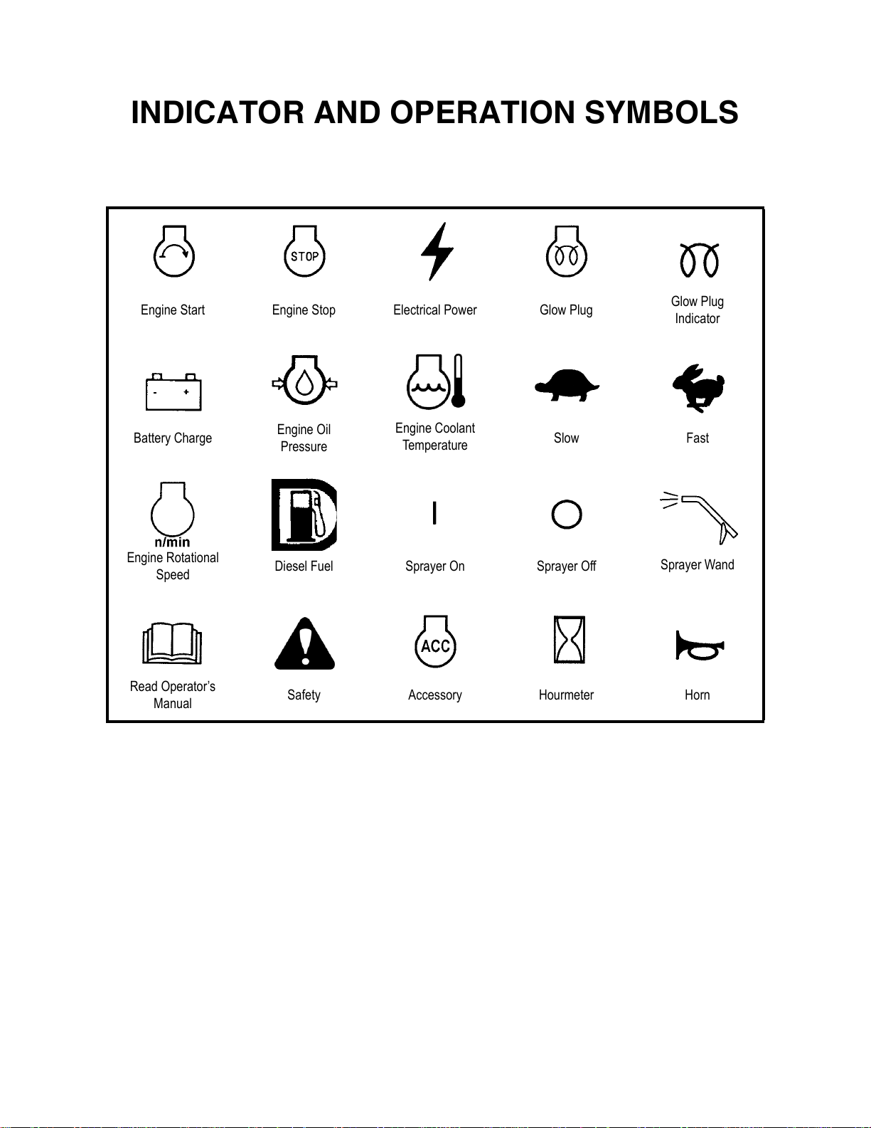
INDICATOR AND OPERATION SYMBOLS
Engine Start Engine Stop Electrical Power Glow Plug
Battery Charge
Engine Rotational
Speed
Read Operator’s
Manual
Engine Oil
Pressure
Diesel Fuel Sprayer On Sprayer Off
Safety Accessory Hourmeter Horn
Engine Coolant
Temperature
Glow Plug
Indicator
Slow Fast
Sprayer Wand
Courtesy of Machine.Market
Page 4

NOTES
Courtesy of Machine.Market
Page 5
TABLE OF CONTENTS
Chapter 1
Introduction . . . . . . . . . . . . . . . . . . . . . . . . . . . . . . . . . . . . . . . . . . . . . . . . . . . . . . . . . . . . . . . . 5
Model/Serial Number Information . . . . . . . . . . . . . . . . . . . . . . . . . . . . . . . . . . . . . . . . . . . . 6
Paver Controls/Components Identification . . . . . . . . . . . . . . . . . . . . . . . . . . . . . . . . . . . . . . 7
Chapter 2
Specifications. . . . . . . . . . . . . . . . . . . . . . . . . . . . . . . . . . . . . . . . . . . . . . . . . . . . . . . . . . . . . . . . 9
Chapter 3
Checklists. . . . . . . . . . . . . . . . . . . . . . . . . . . . . . . . . . . . . . . . . . . . . . . . . . . . . . . . . . . . . . . . . . 11
Chapter 4
Safety . . . . . . . . . . . . . . . . . . . . . . . . . . . . . . . . . . . . . . . . . . . . . . . . . . . . . . . . . . . . . . . . . . . . . 15
Mandatory Safety Shutdown Procedure . . . . . . . . . . . . . . . . . . . . . . . . . . . . . . . . . . . . . . . 15
Safety Reminders . . . . . . . . . . . . . . . . . . . . . . . . . . . . . . . . . . . . . . . . . . . . . . . . . . . . . . . . . 15
Pre-operation Safety Reminders . . . . . . . . . . . . . . . . . . . . . . . . . . . . . . . . . . . . . . . . . . . . . 16
Operation Safety Reminders . . . . . . . . . . . . . . . . . . . . . . . . . . . . . . . . . . . . . . . . . . . . . . . . 16
Service Safety Reminders . . . . . . . . . . . . . . . . . . . . . . . . . . . . . . . . . . . . . . . . . . . . . . . . . . 16
Screed Propane Heater Safety Reminders . . . . . . . . . . . . . . . . . . . . . . . . . . . . . . . . . . . . . . 17
Modifications, Nameplates, Markings and Capacities . . . . . . . . . . . . . . . . . . . . . . . . . . . . 18
Protective Guards and Warning Devices . . . . . . . . . . . . . . . . . . . . . . . . . . . . . . . . . . . . . . . 18
Replacement Parts . . . . . . . . . . . . . . . . . . . . . . . . . . . . . . . . . . . . . . . . . . . . . . . . . . . . . . . . 18
Safety Decals . . . . . . . . . . . . . . . . . . . . . . . . . . . . . . . . . . . . . . . . . . . . . . . . . . . . . . . . . . . . 19
Chapter 5
Indicators and Controls . . . . . . . . . . . . . . . . . . . . . . . . . . . . . . . . . . . . . . . . . . . . . . . . . . . . . . 23
Guards and Shields . . . . . . . . . . . . . . . . . . . . . . . . . . . . . . . . . . . . . . . . . . . . . . . . . . . . . . . 24
Circuit Breaker and In-line Fuses . . . . . . . . . . . . . . . . . . . . . . . . . . . . . . . . . . . . . . . . . . . . 24
Indicator and Control Descriptions . . . . . . . . . . . . . . . . . . . . . . . . . . . . . . . . . . . . . . . . . . . 24
Ignition Keyswitch . . . . . . . . . . . . . . . . . . . . . . . . . . . . . . . . . . . . . . . . . . . . . . . . . . . . . 24
Instrument Module . . . . . . . . . . . . . . . . . . . . . . . . . . . . . . . . . . . . . . . . . . . . . . . . . . . . . 25
Engine Throttle. . . . . . . . . . . . . . . . . . . . . . . . . . . . . . . . . . . . . . . . . . . . . . . . . . . . . . . . 25
Horn . . . . . . . . . . . . . . . . . . . . . . . . . . . . . . . . . . . . . . . . . . . . . . . . . . . . . . . . . . . . . . . . 26
Fuel Level Indicator . . . . . . . . . . . . . . . . . . . . . . . . . . . . . . . . . . . . . . . . . . . . . . . . . . . . 26
Engine Coolant Temperature Indicator . . . . . . . . . . . . . . . . . . . . . . . . . . . . . . . . . . . . . 26
Hourmeter. . . . . . . . . . . . . . . . . . . . . . . . . . . . . . . . . . . . . . . . . . . . . . . . . . . . . . . . . . . . 26
Washdown Sprayer System . . . . . . . . . . . . . . . . . . . . . . . . . . . . . . . . . . . . . . . . . . . . . . 27
Hydraulic Fluid Reservoir Fill . . . . . . . . . . . . . . . . . . . . . . . . . . . . . . . . . . . . . . . . . . . . 27
Paving Alignment Guide . . . . . . . . . . . . . . . . . . . . . . . . . . . . . . . . . . . . . . . . . . . . . . . . 27
Travel Controls. . . . . . . . . . . . . . . . . . . . . . . . . . . . . . . . . . . . . . . . . . . . . . . . . . . . . . . . 28
Hydraulic Pump Variable-Speed Control Lever . . . . . . . . . . . . . . . . . . . . . . . . . . . 28
Travel Control Levers. . . . . . . . . . . . . . . . . . . . . . . . . . . . . . . . . . . . . . . . . . . . . . . . 28
Hopper Controls . . . . . . . . . . . . . . . . . . . . . . . . . . . . . . . . . . . . . . . . . . . . . . . . . . . . . . . 29
Hopper Floor Control Lever . . . . . . . . . . . . . . . . . . . . . . . . . . . . . . . . . . . . . . . . . . . 29
Flow Gate Control Levers . . . . . . . . . . . . . . . . . . . . . . . . . . . . . . . . . . . . . . . . . . . . 29
Printed in U.S.A 1 918215/CP0407
Courtesy of Machine.Market
Page 6
TABLE OF CONTENTS 1448 PLUS
Feed Auger Control Levers . . . . . . . . . . . . . . . . . . . . . . . . . . . . . . . . . . . . . . . . . . . 29
Screed Platform Controls . . . . . . . . . . . . . . . . . . . . . . . . . . . . . . . . . . . . . . . . . . . . . . . . 29
Screed Lift Control Lever . . . . . . . . . . . . . . . . . . . . . . . . . . . . . . . . . . . . . . . . . . . . 29
Vibrator Control Lever. . . . . . . . . . . . . . . . . . . . . . . . . . . . . . . . . . . . . . . . . . . . . . . 29
Screed Extension Control Levers. . . . . . . . . . . . . . . . . . . . . . . . . . . . . . . . . . . . . . . 29
Screed Depth Adjustment . . . . . . . . . . . . . . . . . . . . . . . . . . . . . . . . . . . . . . . . . . . . 30
Side Shoe Plate Adjustment. . . . . . . . . . . . . . . . . . . . . . . . . . . . . . . . . . . . . . . . . . . 30
Mat Crown Adjustment . . . . . . . . . . . . . . . . . . . . . . . . . . . . . . . . . . . . . . . . . . . . . . 30
Screed Propane Heater Kit (Option) . . . . . . . . . . . . . . . . . . . . . . . . . . . . . . . . . . . . 30
Accessories . . . . . . . . . . . . . . . . . . . . . . . . . . . . . . . . . . . . . . . . . . . . . . . . . . . . . . . . . . . . . 31
Chapter 6
Maintenance . . . . . . . . . . . . . . . . . . . . . . . . . . . . . . . . . . . . . . . . . . . . . . . . . . . . . . . . . . . . . . . 33
Maintenance Log . . . . . . . . . . . . . . . . . . . . . . . . . . . . . . . . . . . . . . . . . . . . . . . . . . . . . . . . . 34
Chapter 7
Operation . . . . . . . . . . . . . . . . . . . . . . . . . . . . . . . . . . . . . . . . . . . . . . . . . . . . . . . . . . . . . . . . . 37
General Information . . . . . . . . . . . . . . . . . . . . . . . . . . . . . . . . . . . . . . . . . . . . . . . . . . . . . . 37
Engine Break-in . . . . . . . . . . . . . . . . . . . . . . . . . . . . . . . . . . . . . . . . . . . . . . . . . . . . . . . 37
Before Starting Engine. . . . . . . . . . . . . . . . . . . . . . . . . . . . . . . . . . . . . . . . . . . . . . . . . . 37
Starting the Engine. . . . . . . . . . . . . . . . . . . . . . . . . . . . . . . . . . . . . . . . . . . . . . . . . . . . . 37
First Time Operation . . . . . . . . . . . . . . . . . . . . . . . . . . . . . . . . . . . . . . . . . . . . . . . . . . . 38
Stopping the Paver . . . . . . . . . . . . . . . . . . . . . . . . . . . . . . . . . . . . . . . . . . . . . . . . . . . . . 38
General Paver Operation . . . . . . . . . . . . . . . . . . . . . . . . . . . . . . . . . . . . . . . . . . . . . . . . 38
Walk-around Inspection . . . . . . . . . . . . . . . . . . . . . . . . . . . . . . . . . . . . . . . . . . . . . . . . . 38
Hands-on Check . . . . . . . . . . . . . . . . . . . . . . . . . . . . . . . . . . . . . . . . . . . . . . . . . . . . . . . 38
Screed Propane Heater Kit Operation (Option) . . . . . . . . . . . . . . . . . . . . . . . . . . . . 39
Paving at the Jobsite. . . . . . . . . . . . . . . . . . . . . . . . . . . . . . . . . . . . . . . . . . . . . . . . . . . . 40
Positioning the Paver . . . . . . . . . . . . . . . . . . . . . . . . . . . . . . . . . . . . . . . . . . . . . . . . 40
Filling the Hopper . . . . . . . . . . . . . . . . . . . . . . . . . . . . . . . . . . . . . . . . . . . . . . . . . . 41
Laying the Asphalt . . . . . . . . . . . . . . . . . . . . . . . . . . . . . . . . . . . . . . . . . . . . . . . . . . 41
Precautions while Paving . . . . . . . . . . . . . . . . . . . . . . . . . . . . . . . . . . . . . . . . . . . . . . . . 42
Handling Asphalt Spills . . . . . . . . . . . . . . . . . . . . . . . . . . . . . . . . . . . . . . . . . . . . . . 42
Highway Travel . . . . . . . . . . . . . . . . . . . . . . . . . . . . . . . . . . . . . . . . . . . . . . . . . . . . . . . 43
Transporting Between Jobsites . . . . . . . . . . . . . . . . . . . . . . . . . . . . . . . . . . . . . . . . 43
Unloading with Ramps. . . . . . . . . . . . . . . . . . . . . . . . . . . . . . . . . . . . . . . . . . . . . . . 45
Towing for More Than One Block. . . . . . . . . . . . . . . . . . . . . . . . . . . . . . . . . . . . . . 46
Transporting for More Than One Day . . . . . . . . . . . . . . . . . . . . . . . . . . . . . . . . . . . 46
Theft Deterrents . . . . . . . . . . . . . . . . . . . . . . . . . . . . . . . . . . . . . . . . . . . . . . . . . . . . . . . 46
918215/CP0407 2 Printed in U.S.A
Courtesy of Machine.Market
Page 7
1448 PLUS TABLE OF CONTENTS
Chapter 8
Lubrication. . . . . . . . . . . . . . . . . . . . . . . . . . . . . . . . . . . . . . . . . . . . . . . . . . . . . . . . . . . . . . . . .47
General Information . . . . . . . . . . . . . . . . . . . . . . . . . . . . . . . . . . . . . . . . . . . . . . . . . . . . . . .47
Lubricants . . . . . . . . . . . . . . . . . . . . . . . . . . . . . . . . . . . . . . . . . . . . . . . . . . . . . . . . . . . 47
Greasing and Lubrication . . . . . . . . . . . . . . . . . . . . . . . . . . . . . . . . . . . . . . . . . . . . . . . 47
Hydraulic Fluid Reservoir . . . . . . . . . . . . . . . . . . . . . . . . . . . . . . . . . . . . . . . . . . . . 47
All Grease Fittings. . . . . . . . . . . . . . . . . . . . . . . . . . . . . . . . . . . . . . . . . . . . . . . . . . 47
Engine Crankcase Oil . . . . . . . . . . . . . . . . . . . . . . . . . . . . . . . . . . . . . . . . . . . . . . . 47
Torque Hubs Gear Oil . . . . . . . . . . . . . . . . . . . . . . . . . . . . . . . . . . . . . . . . . . . . . . . 47
Grease Fitting Locations . . . . . . . . . . . . . . . . . . . . . . . . . . . . . . . . . . . . . . . . . . . . . . . . 48
Chapter 9
Schematics . . . . . . . . . . . . . . . . . . . . . . . . . . . . . . . . . . . . . . . . . . . . . . . . . . . . . . . . . . . . . . . . .49
Electrical Schematic . . . . . . . . . . . . . . . . . . . . . . . . . . . . . . . . . . . . . . . . . . . . . . . . . . . . . . .50
Hydraulic Schematic . . . . . . . . . . . . . . . . . . . . . . . . . . . . . . . . . . . . . . . . . . . . . . . . . . . . . . .51
Chapter 10
Service and Storage . . . . . . . . . . . . . . . . . . . . . . . . . . . . . . . . . . . . . . . . . . . . . . . . . . . . . . . . . .53
General Information . . . . . . . . . . . . . . . . . . . . . . . . . . . . . . . . . . . . . . . . . . . . . . . . . . . . . . .53
Precautions. . . . . . . . . . . . . . . . . . . . . . . . . . . . . . . . . . . . . . . . . . . . . . . . . . . . . . . . . . . 53
Dealer Services . . . . . . . . . . . . . . . . . . . . . . . . . . . . . . . . . . . . . . . . . . . . . . . . . . . . . . . . . . .53
Engine Components. . . . . . . . . . . . . . . . . . . . . . . . . . . . . . . . . . . . . . . . . . . . . . . . . . . . 53
Hydraulic System Components . . . . . . . . . . . . . . . . . . . . . . . . . . . . . . . . . . . . . . . . 53
Electrical Components. . . . . . . . . . . . . . . . . . . . . . . . . . . . . . . . . . . . . . . . . . . . . . . 53
Operator Services . . . . . . . . . . . . . . . . . . . . . . . . . . . . . . . . . . . . . . . . . . . . . . . . . . . . . . . . .54
Service Every 10 Hours or Daily. . . . . . . . . . . . . . . . . . . . . . . . . . . . . . . . . . . . . . . . . . 54
Spraying Asphalt Contact Areas . . . . . . . . . . . . . . . . . . . . . . . . . . . . . . . . . . . . . . . 54
Check Fuel Tank Level . . . . . . . . . . . . . . . . . . . . . . . . . . . . . . . . . . . . . . . . . . . . . . 55
Check Engine Oil Level . . . . . . . . . . . . . . . . . . . . . . . . . . . . . . . . . . . . . . . . . . . . . 55
Check Radiator Coolant Level . . . . . . . . . . . . . . . . . . . . . . . . . . . . . . . . . . . . . . . . 55
Check Instrument Operation . . . . . . . . . . . . . . . . . . . . . . . . . . . . . . . . . . . . . . . . . . 55
Check Paver Operation and Condition . . . . . . . . . . . . . . . . . . . . . . . . . . . . . . . . . . 55
Service Every 50 Hours or Weekly . . . . . . . . . . . . . . . . . . . . . . . . . . . . . . . . . . . . . . . . 56
Check Fan Belt . . . . . . . . . . . . . . . . . . . . . . . . . . . . . . . . . . . . . . . . . . . . . . . . . . . . 56
Check Hydraulic Oil Level . . . . . . . . . . . . . . . . . . . . . . . . . . . . . . . . . . . . . . . . . . . 56
Check Battery Connections/Cables . . . . . . . . . . . . . . . . . . . . . . . . . . . . . . . . . . . . . 56
Air Cleaner Element Maintenance . . . . . . . . . . . . . . . . . . . . . . . . . . . . . . . . . . . . . 58
Lubricate Grease Points. . . . . . . . . . . . . . . . . . . . . . . . . . . . . . . . . . . . . . . . . . . . . . 58
Service Every 250 Hours. . . . . . . . . . . . . . . . . . . . . . . . . . . . . . . . . . . . . . . . . . . . . . . . 58
Check Screed Bottom Plate . . . . . . . . . . . . . . . . . . . . . . . . . . . . . . . . . . . . . . . . . . . 58
Change Hydraulic Filter . . . . . . . . . . . . . . . . . . . . . . . . . . . . . . . . . . . . . . . . . . . . . 59
Change Engine Oil and Filter . . . . . . . . . . . . . . . . . . . . . . . . . . . . . . . . . . . . . . . . . 59
Check Torque Hub Oil Level . . . . . . . . . . . . . . . . . . . . . . . . . . . . . . . . . . . . . . . . . . . . . . . .60
Service Every 500 Hours. . . . . . . . . . . . . . . . . . . . . . . . . . . . . . . . . . . . . . . . . . . . . . . . 60
Change Fuel Filter . . . . . . . . . . . . . . . . . . . . . . . . . . . . . . . . . . . . . . . . . . . . . . . . . . 60
Service Every 1000 Hours
or Each Season. . . . . . . . . . . . . . . . . . . . . . . . . . . . . . . . . . . . . . . . . . . . . . . . . . . . . . . . 61
Change Radiator Coolant. . . . . . . . . . . . . . . . . . . . . . . . . . . . . . . . . . . . . . . . . . . . . 61
Printed in U.S.A 3 918215/CP0407
Courtesy of Machine.Market
Page 8
TABLE OF CONTENTS 1448 PLUS
Replace Hydraulic Oil and Strainer . . . . . . . . . . . . . . . . . . . . . . . . . . . . . . . . . . . . . 61
Check Exhaust System. . . . . . . . . . . . . . . . . . . . . . . . . . . . . . . . . . . . . . . . . . . . . . . 62
Adjusting Variable Speed Control . . . . . . . . . . . . . . . . . . . . . . . . . . . . . . . . . . . . . . . . . 62
Storage . . . . . . . . . . . . . . . . . . . . . . . . . . . . . . . . . . . . . . . . . . . . . . . . . . . . . . . . . . . . . . 62
Before Storage . . . . . . . . . . . . . . . . . . . . . . . . . . . . . . . . . . . . . . . . . . . . . . . . . . . . . 62
During Storage . . . . . . . . . . . . . . . . . . . . . . . . . . . . . . . . . . . . . . . . . . . . . . . . . . . . . 63
After Storage . . . . . . . . . . . . . . . . . . . . . . . . . . . . . . . . . . . . . . . . . . . . . . . . . . . . . . 63
Chapter 11
Troubleshooting . . . . . . . . . . . . . . . . . . . . . . . . . . . . . . . . . . . . . . . . . . . . . . . . . . . . . . . . . . . . 65
Engine . . . . . . . . . . . . . . . . . . . . . . . . . . . . . . . . . . . . . . . . . . . . . . . . . . . . . . . . . . . . . . . . . 65
General Paver Problems During Operation . . . . . . . . . . . . . . . . . . . . . . . . . . . . . . . . . . . . . 66
Paver-Related Mat Problems . . . . . . . . . . . . . . . . . . . . . . . . . . . . . . . . . . . . . . . . . . . . . . . . 66
Material-Delivery, Compaction-Related Mat Problems . . . . . . . . . . . . . . . . . . . . . . . . . . . 67
Drive and Main Control Valves . . . . . . . . . . . . . . . . . . . . . . . . . . . . . . . . . . . . . . . . . . . . . 68
Hydraulic Pump and Motor System . . . . . . . . . . . . . . . . . . . . . . . . . . . . . . . . . . . . . . . . . . 69
Hydraulic Cylinders . . . . . . . . . . . . . . . . . . . . . . . . . . . . . . . . . . . . . . . . . . . . . . . . . . . . . . 69
Electrical System . . . . . . . . . . . . . . . . . . . . . . . . . . . . . . . . . . . . . . . . . . . . . . . . . . . . . . . . . 69
Chapter 12
Decal Locations. . . . . . . . . . . . . . . . . . . . . . . . . . . . . . . . . . . . . . . . . . . . . . . . . . . . . . . . . . . . . 73
General Information . . . . . . . . . . . . . . . . . . . . . . . . . . . . . . . . . . . . . . . . . . . . . . . . . . . . . . 73
New Decal Application . . . . . . . . . . . . . . . . . . . . . . . . . . . . . . . . . . . . . . . . . . . . . . . . . . . . 73
Index . . . . . . . . . . . . . . . . . . . . . . . . . . . . . . . . . . . . . . . . . . . . . . . . . . . . . . . . . . . . . . . . . . . . . 77
Torque Specifications . . . . . . . . . . . . . . . . . . . . . . . . . . . . . . . . . . . . . . . . . . . . . . . . . . . . . . . 79
918215/CP0407 4 Printed in U.S.A
Courtesy of Machine.Market
Page 9

Chapter 1
INTRODUCTION
The information in this Operator’s Manual was written to give the owner/operator assistance in preparing,
adjusting, maintaining and servicing of the paver. More important, this manual provides an operating plan
for safe and proper use of the machine. Major points of safe operation are detailed in the SAFETY chapter
of this manual.
GEHL Company asks that you read and understand the contents of this manual COMPLETELY and
become familiar with the machine, before operating it.
The use of this asphalt paver (referred to as paver throughout the rest of the manual) is subject to certain
hazards that cannot be eliminated by mechanical means, but only by the exercise of intelligence, care and
common sense. It is therefore essential to have competent and careful operators, who are not physically or
mentally impaired, and who are thoroughly trained in the safe operation of the equipment.
Throughout this manual information is provided that is set in italic type and introduced by the word
IMPORTANT or NOTE. Be sure to read carefully and comply with the message or directive given. Fol-
lowing this information will improve operating and maintenance efficiency, help to avoid breakdowns and
damage, and extend the machine’s life. A chart of standard hardware torques is located in the back of this
manual. “Right” and “left” are determined from a position standing on the screed and facing forward.
A storage compartment is provided on the unit for storing the Operator’s Manual. After using the manual,
please return it to the storage compartment and keep it with the unit at all times! If the machine is resold,
GEHL Company recommends that this manual be given to the new owner.
If this machine was purchased "used," or if the owner's address has changed, please provide your GEHL
dealer or GEHL Company Service Department with the owner's name and current address, along with the
machine model and serial number. This will allow the registered owner information to be updated, so that
the owner can be notified directly in case of an important product issue, such as a safety update program.
The wide GEHL dealership network stands ready to provide any assistance that may be required, including
genuine GEHL service parts. All parts should be obtained from or ordered through your GEHL dealer.
Give complete information about the part and include the model and serial number of the machine. Record
the serial number in the space provided in “Model/Serial Number Information” on page 6, as a handy
record for quick reference.
GEHL Company reserves the right to make changes or improvements in the design or construction of any
part without incurring the obligation to install such changes on any unit previously delivered.
GEHL Company, in cooperation with the Society of Automotive
Engineers, has adopted this
Safety Alert Symbol
to identify potential safety hazards, which, if not properly avoided, could
result in injury. When you see this symbol in this manual or on the
machine itself, you are reminded to BE ALERT! Your personal safety is
involved!
Printed in U.S.A 5 918215/CP0407
Courtesy of Machine.Market
Page 10
INTRODUCTION 1448 PLUS
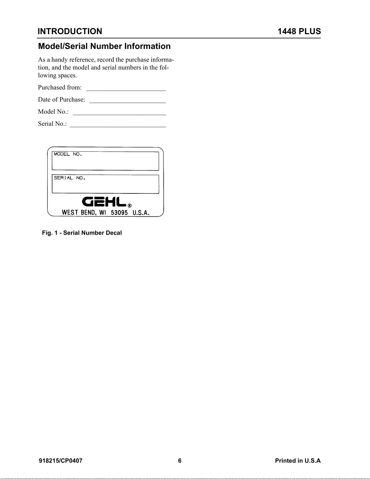
Model/Serial Number Information
As a handy reference, record the purchase informa-
tion, and the model and serial numbers in the fol-
lowing spaces.
Purchased from: ________________________
Date of Purchase: _______________________
Model No.: ____________________________
Serial No.: _____________________________
Fig. 1 - Serial Number Decal
918215/CP0407 6 Printed in U.S.A
Courtesy of Machine.Market
Page 11
1448 PLUS INTRODUCTION
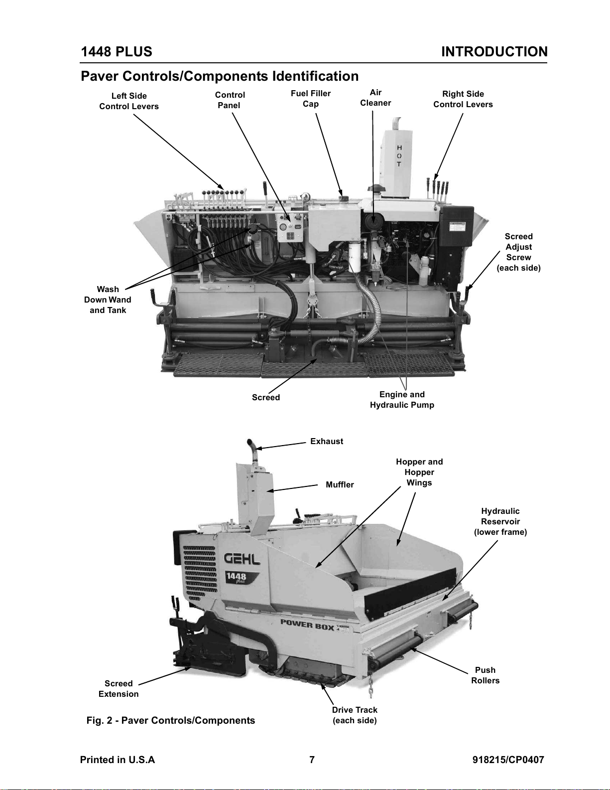
Paver Controls/Components Identification
Left Side
Control Levers
Wash
Down Wand
and Tank
Control
Panel
Fuel Filler
Cap
Air
Cleaner
Right Side
Control Levers
Screed
Adjust
Screw
(each side)
Screed
Extension
Fig. 2 - Paver Controls/Components
Screed
Exhaust
Muffler
Drive Track
(each side)
Engine and
Hydraulic Pump
Hopper and
Hopper
Wings
Hydraulic
Reservoir
(lower frame)
Push
Rollers
Printed in U.S.A 7 918215/CP0407
Courtesy of Machine.Market
Page 12

INTRODUCTION 1448 PLUS
NOTES
918215/CP0407 8 Printed in U.S.A
Courtesy of Machine.Market
Page 13

Chapter 2
SPECIFICATIONS
DIMENSIONS, MEASURES AND WEIGHTS
Overall Height (top of exhaust pipe) 6’11” (2108 mm)
Minimum Width (transport) 8’5” (2565 mm)
Maximum Width (operating) 10’9” (3277 mm)
Length 7’4” (2235 mm)
Truck Clearance (height from ground to
asphalt hopper floor)
Weight (approximate) 7775 lbs. (3527 kg)
ENGINE
Engine Model Yanmar 3TNV88-XGP
Type Vertical In-line 3-cylinder
Horsepower (net) @ Engine Speed 36 (27 kW) @ 3000 rpm
Displacement 100 cu. in. (1.642 L)
Aspiration Natural
Bore and Stroke 3.46” x 3.54” (88 x 90 mm)
Weight 342 lbs. (155 kg)
Power Take Off Location Flywheel side
Direction of Rotation Counter-clockwise (viewed from flywheel side)
Dimensions (L x W x H) 22.2 x 19.1 x 24.4” (564 x 486 x 622 mm)
Max. Torque @ Engine Speed 80 lb.-ft. (108 Nm) @ 1200 rpm
Max. Engine Speed (with no load) 3210±25 rpm
Lubricating System Forced lubrication with trochoid pump
Fuel Injection System Direct Injection
Engine Cooling System 4.0 qts. (3.8 L)
Engine Oil Capacity 7 qts. (6.7 L)
Cooling Fan 14-11/16” (373 mm) dia., 8-blade, pusher type
Starting Aid Intake Air Heater (preheating time: 15 seconds)
23” (584 mm)
Water-cooled Diesel
SCREED
Main Width 8”-12” (2438-3658 mm)
Hydraulic Vibrator 2500 vpm - maximum
Heat Medium Exhaust (standard); Propane (option)
Variable Hydraulic Screed Extension -
Max. Extension Length
Maximum Variable Crown/Invert 0”-2” (0-51 mm)
Extension Width 24” (610 mm)
Single-Span Operator Platform Type Stationary (standard)
24” (610 mm) w/ 6”strike-off
MATERIAL FLOW
Independent Hyraulic Operated Gates Standard
Gate Cut-Off Plates Option, 6”-36” (152-915 mm)
Gravity-Flow Asphalt Hopper Capacity 4 Tons (3629 Kg)
Independent Hydraulic Operating Augers Located on Gate
Printed in U.S.A 9 918215/CP0407
Courtesy of Machine.Market
Page 14
SPECIFICATIONS 1448 PLUS
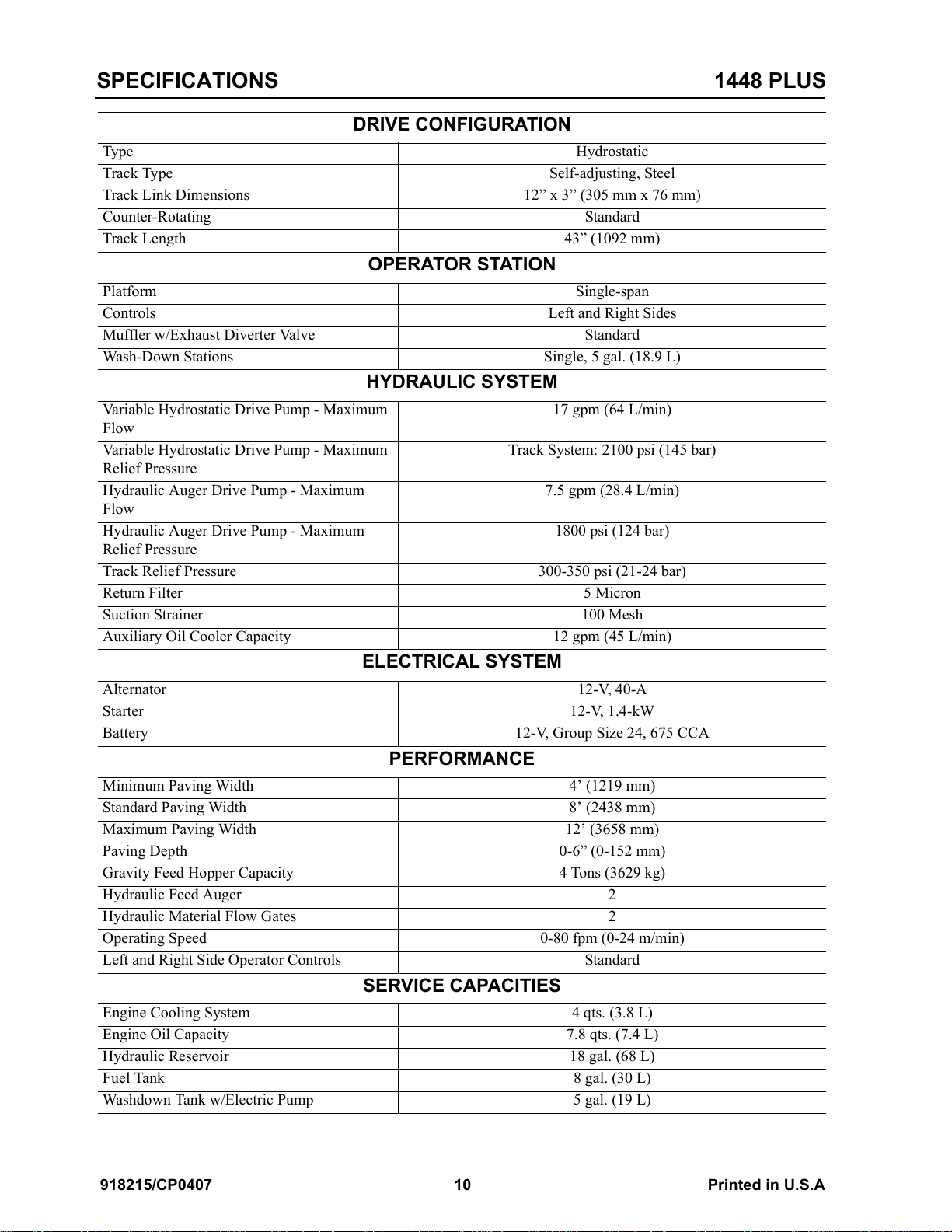
DRIVE CONFIGURATION
Type Hydrostatic
Track Type Self-adjusting, Steel
Track Link Dimensions 12” x 3” (305 mm x 76 mm)
Counter-Rotating Standard
Track Length 43” (1092 mm)
OPERATOR STATION
Platform Single-span
Controls Left and Right Sides
Muffler w/Exhaust Diverter Valve Standard
Wash-Down Stations Single, 5 gal. (18.9 L)
HYDRAULIC SYSTEM
Variable Hydrostatic Drive Pump - Maximum
Flow
Variable Hydrostatic Drive Pump - Maximum
Relief Pressure
Hydraulic Auger Drive Pump - Maximum
Flow
Hydraulic Auger Drive Pump - Maximum
Relief Pressure
Track Relief Pressure 300-350 psi (21-24 bar)
Return Filter 5 Micron
Suction Strainer 100 Mesh
Auxiliary Oil Cooler Capacity 12 gpm (45 L/min)
17 gpm (64 L/min)
Track System: 2100 psi (145 bar)
7.5 gpm (28.4 L/min)
1800 psi (124 bar)
ELECTRICAL SYSTEM
Alternator 12-V, 40-A
Starter 12-V, 1.4-kW
Battery 12-V, Group Size 24, 675 CCA
PERFORMANCE
Minimum Paving Width 4’ (1219 mm)
Standard Paving Width 8’ (2438 mm)
Maximum Paving Width 12’ (3658 mm)
Paving Depth 0-6” (0-152 mm)
Gravity Feed Hopper Capacity 4 Tons (3629 kg)
Hydraulic Feed Auger 2
Hydraulic Material Flow Gates 2
Operating Speed 0-80 fpm (0-24 m/min)
Left and Right Side Operator Controls Standard
SERVICE CAPACITIES
Engine Cooling System 4 qts. (3.8 L)
Engine Oil Capacity 7.8 qts. (7.4 L)
Hydraulic Reservoir 18 gal. (68 L)
Fuel Tank 8 gal. (30 L)
Washdown Tank w/Electric Pump 5 gal. (19 L)
918215/CP0407 10 Printed in U.S.A
Courtesy of Machine.Market
Page 15
Chapter 3
CHECKLISTS
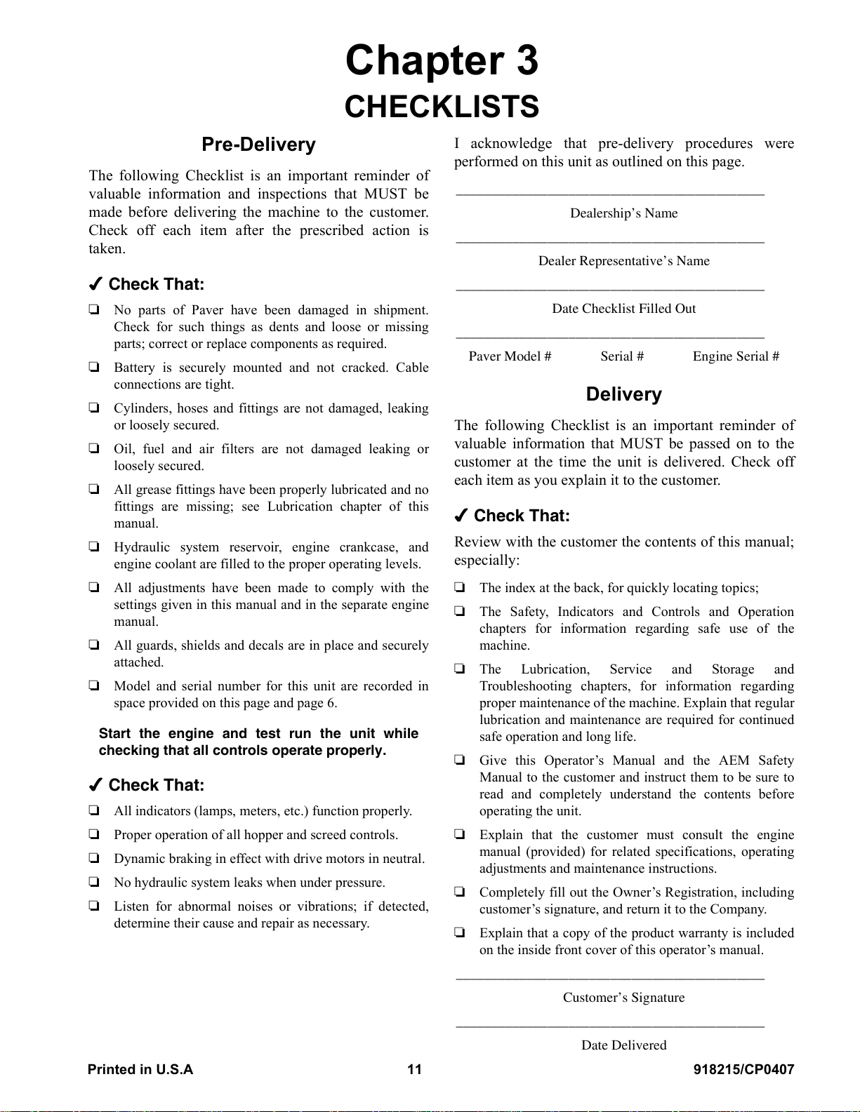
Pre-Delivery
The following Checklist is an important reminder of
valuable information and inspections that MUST be
made before delivering the machine to the customer.
Check off each item after the prescribed action is
taken.
Check That:
R No parts of Paver have been damaged in shipment.
Check for such things as dents and loose or missing
parts; correct or replace components as required.
R Battery is securely mounted and not cracked. Cable
connections are tight.
R Cylinders, hoses and fittings are not damaged, leaking
or loosely secured.
R Oil, fuel and air filters are not damaged leaking or
loosely secured.
R All grease fittings have been properly lubricated and no
fittings are missing; see Lubrication chapter of this
manual.
R Hydraulic system reservoir, engine crankcase, and
engine coolant are filled to the proper operating levels.
I acknowledge that pre-delivery procedures were
performed on this unit as outlined on this page.
____________________________________________
Dealership’s Name
____________________________________________
Dealer Representative’s Name
____________________________________________
Date Checklist Filled Out
____________________________________________
Paver Model # Serial # Engine Serial #
Delivery
The following Checklist is an important reminder of
valuable information that MUST be passed on to the
customer at the time the unit is delivered. Check off
each item as you explain it to the customer.
Check That:
Review with the customer the contents of this manual;
especially:
R All adjustments have been made to comply with the
settings given in this manual and in the separate engine
manual.
R All guards, shields and decals are in place and securely
attached.
R Model and serial number for this unit are recorded in
space provided on this page and page 6.
Start the engine and test run the unit while
checking that all controls operate properly.
Check That:
R All indicators (lamps, meters, etc.) function properly.
R Proper operation of all hopper and screed controls.
R Dynamic braking in effect with drive motors in neutral.
R No hydraulic system leaks when under pressure.
R Listen for abnormal noises or vibrations; if detected,
determine their cause and repair as necessary.
R The index at the back, for quickly locating topics;
R The Safety, Indicators and Controls and Operation
chapters for information regarding safe use of the
machine.
R The Lubrication, Service and Storage and
Troubleshooting chapters, for information regarding
proper maintenance of the machine. Explain that regular
lubrication and maintenance are required for continued
safe operation and long life.
R Give this Operator’s Manual and the AEM Safety
Manual to the customer and instruct them to be sure to
read and completely understand the contents before
operating the unit.
R Explain that the customer must consult the engine
manual (provided) for related specifications, operating
adjustments and maintenance instructions.
R Completely fill out the Owner’s Registration, including
customer’s signature, and return it to the Company.
R Explain that a copy of the product warranty is included
on the inside front cover of this operator’s manual.
____________________________________________
Customer’s Signature
____________________________________________
Date Delivered
Printed in U.S.A 11 918215/CP0407
Courtesy of Machine.Market
Page 16

CHECKLISTS 1448 PLUS
NOTES
918215/CP0407 12 Printed in U.S.A
Courtesy of Machine.Market
Page 17
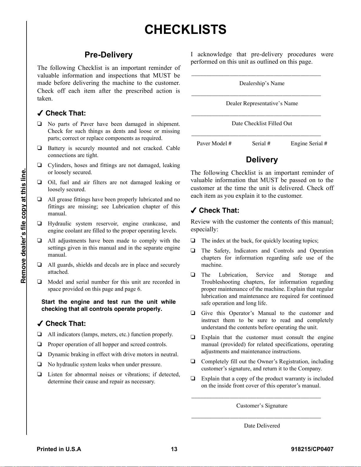
CHECKLISTS
Pre-Delivery
The following Checklist is an important reminder of
valuable information and inspections that MUST be
made before delivering the machine to the customer.
Check off each item after the prescribed action is
taken.
Check That:
R No parts of Paver have been damaged in shipment.
Check for such things as dents and loose or missing
parts; correct or replace components as required.
R Battery is securely mounted and not cracked. Cable
connections are tight.
R Cylinders, hoses and fittings are not damaged, leaking
or loosely secured.
R Oil, fuel and air filters are not damaged leaking or
loosely secured.
R All grease fittings have been properly lubricated and no
fittings are missing; see Lubrication chapter of this
manual.
R Hydraulic system reservoir, engine crankcase, and
engine coolant are filled to the proper operating levels.
I acknowledge that pre-delivery procedures were
performed on this unit as outlined on this page.
____________________________________________
Dealership’s Name
____________________________________________
Dealer Representative’s Name
____________________________________________
Date Checklist Filled Out
____________________________________________
Paver Model # Serial # Engine Serial #
Delivery
The following Checklist is an important reminder of
valuable information that MUST be passed on to the
customer at the time the unit is delivered. Check off
each item as you explain it to the customer.
Check That:
Review with the customer the contents of this manual;
especially:
R All adjustments have been made to comply with the
settings given in this manual and in the separate engine
manual.
R All guards, shields and decals are in place and securely
attached.
Remove dealer’s file copy at this line.
R Model and serial number for this unit are recorded in
space provided on this page and page 6.
Start the engine and test run the unit while
checking that all controls operate properly.
Check That:
R All indicators (lamps, meters, etc.) function properly.
R Proper operation of all hopper and screed controls.
R Dynamic braking in effect with drive motors in neutral.
R No hydraulic system leaks when under pressure.
R Listen for abnormal noises or vibrations; if detected,
determine their cause and repair as necessary.
R The index at the back, for quickly locating topics;
R The Safety, Indicators and Controls and Operation
chapters for information regarding safe use of the
machine.
R The Lubrication, Service and Storage and
Troubleshooting chapters, for information regarding
proper maintenance of the machine. Explain that regular
lubrication and maintenance are required for continued
safe operation and long life.
R Give this Operator’s Manual to the customer and
instruct them to be sure to read and completely
understand the contents before operating the unit.
R Explain that the customer must consult the engine
manual (provided) for related specifications, operating
adjustments and maintenance instructions.
R Completely fill out the Owner’s Registration, including
customer’s signature, and return it to the Company.
R Explain that a copy of the product warranty is included
on the inside front cover of this operator’s manual.
____________________________________________
Customer’s Signature
____________________________________________
Date Delivered
Printed in U.S.A 13 918215/CP0407
Courtesy of Machine.Market
Page 18

CHECKLISTS 1448 PLUS
NOTES
918215/CP0407 14 Printed in U.S.A
Courtesy of Machine.Market
Page 19
Chapter 4
SAFETY
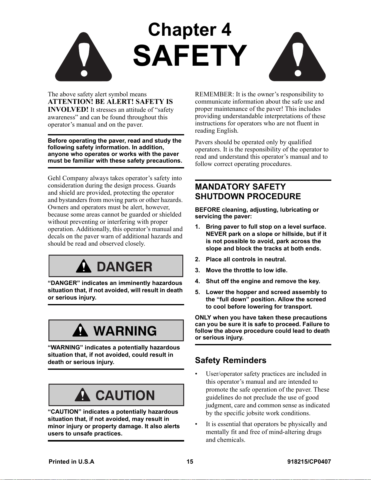
The above safety alert symbol means
ATTENTION! BE ALERT! SAFETY IS
INVOLVED! It stresses an attitude of “safety
awareness” and can be found throughout this
operator’s manual and on the paver.
Before operating the paver, read and study the
following safety information. In addition,
anyone who operates or works with the paver
must be familiar with these safety precautions.
Gehl Company always takes operator’s safety into
consideration during the design process. Guards
and shield are provided, protecting the operator
and bystanders from moving parts or other hazards.
Owners and operators must be alert, however,
because some areas cannot be guarded or shielded
without preventing or interfering with proper
operation. Additionally, this operator’s manual and
decals on the paver warn of additional hazards and
should be read and observed closely.
DANGER
REMEMBER: It is the owner’s responsibility to
communicate information about the safe use and
proper maintenance of the paver! This includes
providing understandable interpretations of these
instructions for operators who are not fluent in
reading English.
Pavers should be operated only by qualified
operators. It is the responsibility of the operator to
read and understand this operator’s manual and to
follow correct operating procedures.
MANDATORY SAFETY
SHUTDOWN PROCEDURE
BEFORE cleaning, adjusting, lubricating or
servicing the paver:
1. Bring paver to full stop on a level surface.
NEVER park on a slope or hillside, but if it
is not possible to avoid, park across the
slope and block the tracks at both ends.
2. Place all controls in neutral.
3. Move the throttle to low idle.
“DANGER” indicates an imminently hazardous
situation that, if not avoided, will result in death
or serious injury.
WARNING
“WARNING” indicates a potentially hazardous
situation that, if not avoided, could result in
death or serious injury.
CAUTION
“CAUTION” indicates a potentially hazardous
situation that, if not avoided, may result in
minor injury or property damage. It also alerts
users to unsafe practices.
4. Shut off the engine and remove the key.
5. Lower the hopper and screed assembly to
the “full down” position. Allow the screed
to cool before lowering for transport.
ONLY when you have taken these precautions
can you be sure it is safe to proceed. Failure to
follow the above procedure could lead to death
or serious injury.
Safety Reminders
• User/operator safety practices are included in
this operator’s manual and are intended to
promote the safe operation of the paver. These
guidelines do not preclude the use of good
judgment, care and common sense as indicated
by the specific jobsite work conditions.
• It is essential that operators be physically and
mentally fit and free of mind-altering drugs
and chemicals.
Printed in U.S.A 15 918215/CP0407
Courtesy of Machine.Market
Page 20
SAFETY
(Continued)
• It is essential that operators be thoroughly
trained in the safe operation of the paver. Such
training should be presented completely to all
new operators and not condensed for those
claiming previous experience.
• Some illustrations in this manual may show
doors, guards and shields open or removed.
This is for illustration purposes only. Be sure
that all doors, guards and shields are in their
proper operating positions before starting the
engine to operate the paver.
Pre-operation Safety Reminders
• Always wear personal protective equipment
appropriate for the job and working conditions.
Hard hats, safety glasses, protective shoes,
gloves, reflective vests, respirators and ear
protection are examples of types of equipment
that may be required. Do not wear loose-fitting
clothing, long hair, jewelry or loose personal
items while operating or servicing the paver.
• Always check the job site for obstructions and
bystanders.
• Always perform a daily inspection of the paver
before using it. Look for damage, loose or
missing parts, leaks, etc.
• Walk around the paver and warn all nearby
personnel before starting the paver.
Operation Safety Reminders
• Do not use ether or other starting fluids to start
the paver engine. Doing so may void the
engine warranty.
• Do not attempt to move hot asphalt mix with
your hands or feet. Contact with hot asphalt
can cause serious skin burns.
• Do not allow minors or any unqualified
personnel to operate or be near the paver
unless properly supervised.
• Do not operate the paver in an enclosed area
without adequate ventilation. Internal
combustion engines deplete the oxygen supply
within enclosed spaces and may create a
serious hazard unless the oxygen is replaced.
• Do not leave the paver unattended with the
engine running. Always lower the hopper to
“full down” position, shut off the engine, and
place all controls in neutral before leaving the
paver.
• Do not jump off the paver. Do not dismount
from the paver while it is moving.
• Check paver for proper functioning of controls
before operating. Observe all gauges and
instruments, and correct any malfunctions
before operating.
• Do not lift the hopper if pushing a dump truck
with the paver. Damage to the paver/truck may
result.
Service Safety Reminders
• Never use your hands to search for hydraulic
fluid leaks. Use a piece of paper or cardboard
instead. Escaping fluid under pressure can be
invisible and can penetrate the skin and cause
serious injury. If any fluid is injected into your
skin, see a doctor at once. Injected fluid must
be surgically removed by a doctor familiar
with this type of injury or gangrene may result.
• Never attempt to bypass the keyswitch to start
the engine. Only use the jump starting
procedure described in this manual. See
“Jump-starting” on page 57.
• Never use fuel for cleaning purposes.
• Always position the safety props up when
leaving the hopper raised for inspection,
cleaning or service.
918215/CP0407 16 Printed in U.S.A
Courtesy of Machine.Market
Page 21
SAFETY
(Continued)
• Always wear safety glasses with side shields
when striking metal against metal. In addition,
it is recommended that a softer (chip-resistent)
material be used to cushion the blow, such as a
brass drift. Failure to follow could lead to
serious injury to the eyes or other parts of the
body.
• Do not refill the fuel tank when the engine is
hot. Allow engine to cool before refilling to
prevent the hot engine from igniting any
spilled or splashed fuel.
• Do not smoke while filling the fuel tank, while
working on the fuel or hydraulic systems, or
while working around the battery or propane
heater.
• Do not attempt to loosen or disconnect any
hydraulic lines, hoses or fittings without first
relieving hydraulic circuit pressure. Also, be
careful not to touch any hydraulic components
that have been in recent operation, because
they can be extremely hot and can cause burns.
• Before performing any service/maintenance on
the paver, always disconnect the battery to
prevent unintentional starting.
• Do not attempt to remove the radiator cap after
the engine has reached operating temperature
or if it is overheated. At operating
temperatures, engine coolant is extremely hot
and under pressure. Always wait for the engine
to cool before attempting to relieve pressure
and remove the radiator cap. Failure to heed
this warning could result in severe burns.
• Dispose of all petroleum-based oils and fluids
properly. Used motor oil may pose a health
risk. Wipe oil from your hands promptly and
wash off any residue. Used motor oil is an
environmental contaminant and may only be
disposed of at approved collection facilities.
Never drain any petroleum-based product on
the ground, dispose of in municipal waste
collection containers, or in metropolitan sewer
systems or landfills. Check state and local
regulations for other requirements.
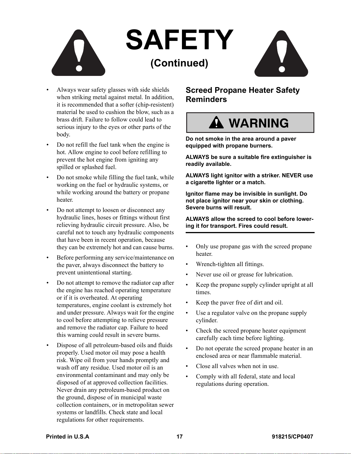
Screed Propane Heater Safety
Reminders
WARNING
Do not smoke in the area around a paver
equipped with propane burners.
ALWAYS be sure a suitable fire extinguisher is
readily available.
ALWAYS light ignitor with a striker. NEVER use
a cigarette lighter or a match.
Ignitor flame may be invisible in sunlight. Do
not place ignitor near your skin or clothing.
Severe burns will result.
ALWAYS allow the screed to cool before lower-
ing it for transport. Fires could result.
• Only use propane gas with the screed propane
heater.
• Wrench-tighten all fittings.
• Never use oil or grease for lubrication.
• Keep the propane supply cylinder upright at all
times.
• Keep the paver free of dirt and oil.
• Use a regulator valve on the propane supply
cylinder.
• Check the screed propane heater equipment
carefully each time before lighting.
• Do not operate the screed propane heater in an
enclosed area or near flammable material.
• Close all valves when not in use.
• Comply with all federal, state and local
regulations during operation.
Printed in U.S.A 17 918215/CP0407
Courtesy of Machine.Market
Page 22

SAFETY
(Continued)
Modifications, Nameplates,
Markings and Capacities
Modifications and additions that affect capacity or
safe operation of the paver must not be performed
without the prior written approval of the Gehl
Company.
Protective Guards and Warning
Devices
The paver is fitted with protective covers over the
engine area in accordance with industry standards.
They are intended to offer protection to the
operator from physical injury.
A horn is provided, which can be activated from
either side of the paver.
Replacement Parts
To ensure continued safe operation, replace
damaged or wornout parts with genuine GEHL
service parts, before operating the paver. If there is
a decal on a part that is to be replaced, be sure that
the replacement part has the decal applied to it.
918215/CP0407 18 Printed in U.S.A
Courtesy of Machine.Market
Page 23
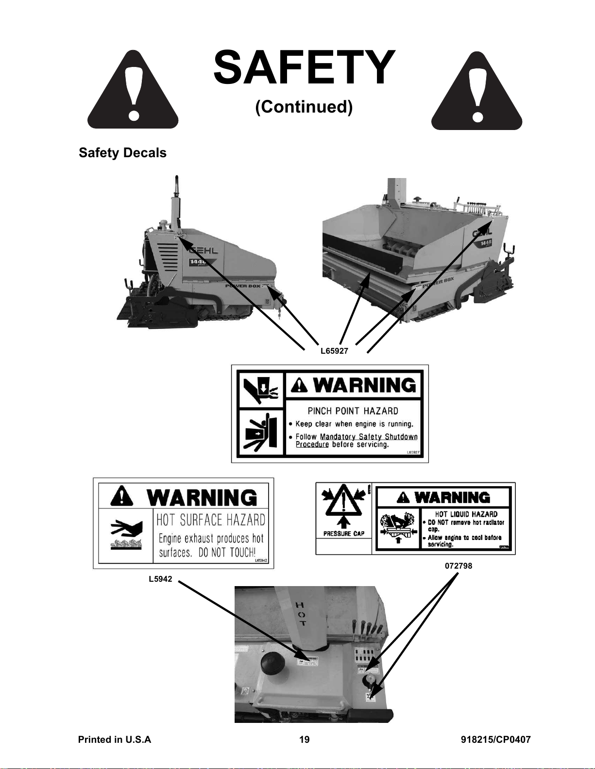
Safety Decals
SAFETY
(Continued)
L65927
072798
L5942
Printed in U.S.A 19 918215/CP0407
Courtesy of Machine.Market
Page 24
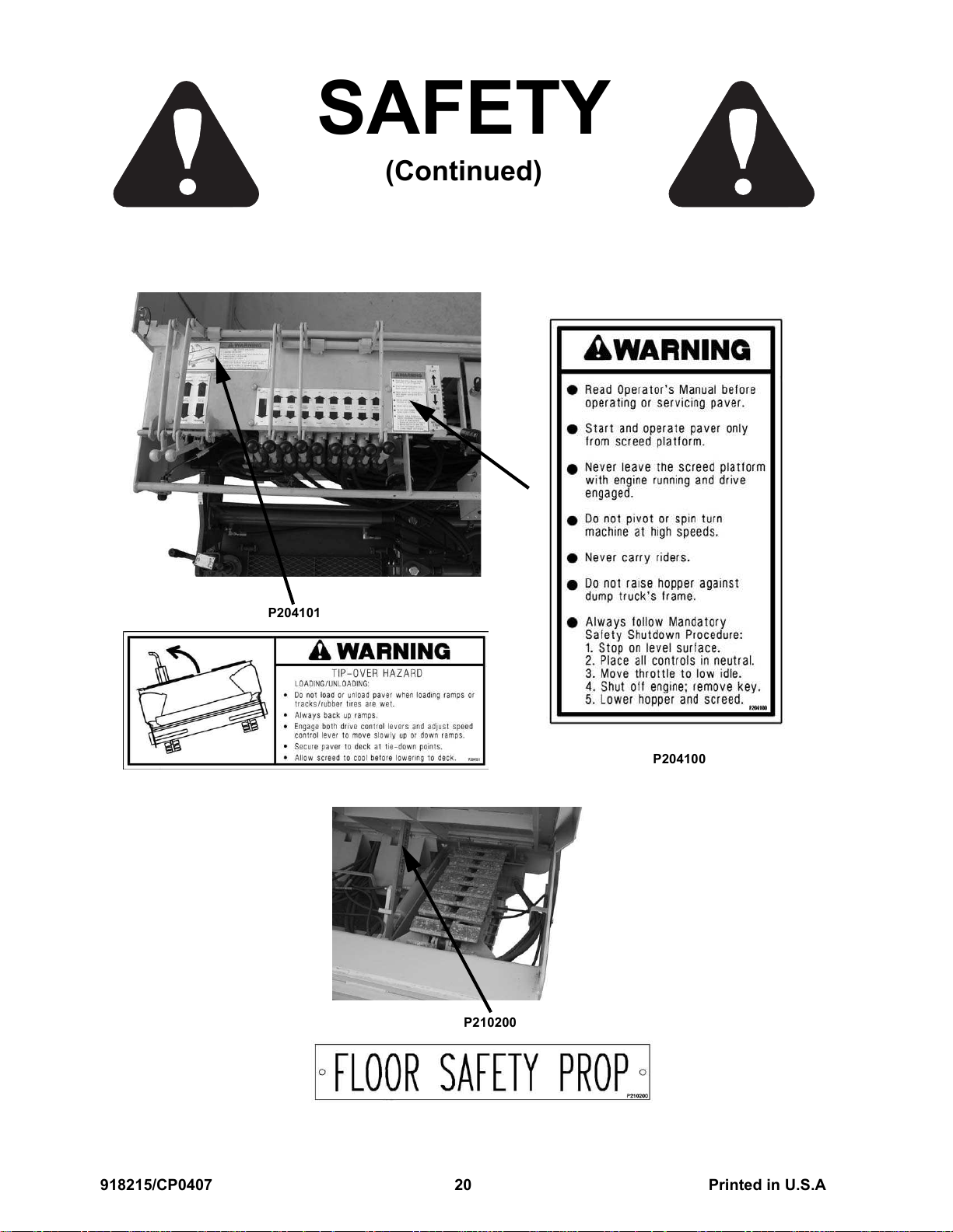
SAFETY
(Continued)
P204101
P204100
P210200
918215/CP0407 20 Printed in U.S.A
Courtesy of Machine.Market
Page 25
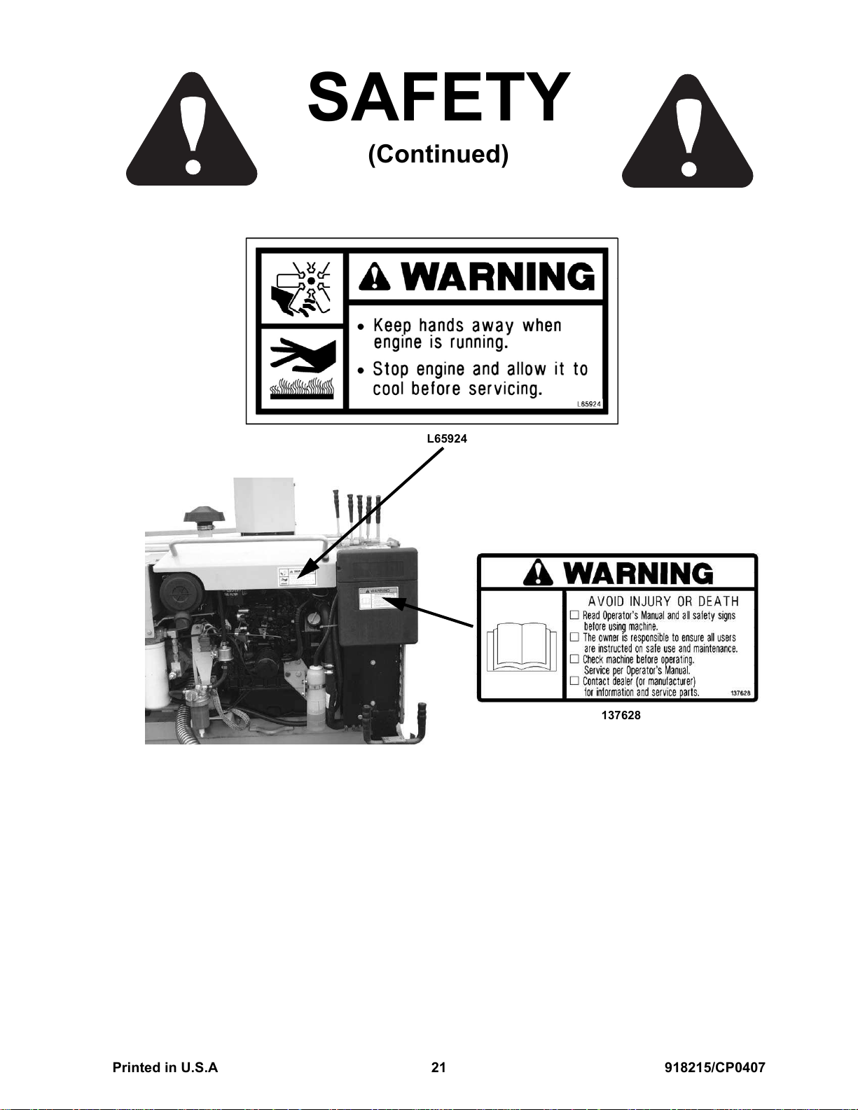
SAFETY
(Continued)
L65924
137628
Printed in U.S.A 21 918215/CP0407
Courtesy of Machine.Market
Page 26

SAFETY
(Continued)
NOTES
918215/CP0407 22 Printed in U.S.A
Courtesy of Machine.Market
Page 27

Chapter 5
INDICATORS AND CONTROLS
Left Control Panel
(backwall)
2
3
1
14
12
13
9 10
8
7
6
5
4
2
5
7
3
11
12
22
15
21
24
16
17
18
19
20
1
Paver Front
23
Right Control Panel
(backwall)
1Horn
2 Left Travel Control
3 Right Travel Control
4 Screed Vibrator Control
5 Hopper Floor Control
6 Left Auger Control
7 Right Auger Control
8 Screed Lift Control
9 Left Flow Gate Control
10 Right Flow Gate Control
11 Left Screed Extension
12 Right Screed Extension
13 Variable Speed Control
14 Fuel Level Indicator
15 Engine Coolant Temperature
16 Engine Throttle
17 Hourmeter
18 Ignition Switch
19 Instrument Module
20 Washdown Sprayer Switch
21 Releasing Agent Reservoir Fill
22 Hydraulic Fluid Reservoir Fill
23 Paving Alignment Guide
24 Exhaust Diverter
Fig. 3 - Indicators and Controls
Printed in U.S.A 23 918215/CP0407
Courtesy of Machine.Market
Page 28

INDICATORS AND CONTROLS 1448 PLUS
Indicator and Control
CAUTION
Before operating the paver, become familiar
with, and know how to use, all safety devices
and controls. Know how to stop the paver
before starting it — refer to “Mandatory Safety
Shutdown Procedure” on page 15.
Descriptions
(Refer to Fig. 3, page 23 for locations)
Ignition Keyswitch
(Item 18, Fig. 3)
Guards and Shields
Whenever possible and without affecting paver
operation, guards and shields are used to protect
potentially hazardous areas. In many places, decals
are also used to warn of potential dangers and to
communicate special operating procedures.
WARNING
Read and thoroughly understand all safety
decals on the paver before operation. Do not
operate the paver unless all factory-installed
guards and shields are properly secured in
place.
Circuit Breaker and In-line Fuses
1
Fig. 4 - Circuit Breaker
The circuit breaker (1, Fig. 4) provides protection
for the entire electrical system. If activated, the
indicator will be extended out. Push in to reset.
In-line fuses, located behind the control panel,
are provided to protect individual components.
Fig. 5 - Keyswitch
STOP Position ( ): When the key is vertical in
the keyswitch, power from the battery is
disconnected from the paver electrical circuits
(except the horn).
NOTE: This is the only position the ignition
key can be inserted or removed from the key
switch.
RUN Position ( ): When the key is rotated
clockwise one position from vertical, power from
the battery is connected to the paver electrical
circuits.
NOTE: The battery charge and engine oil
pressure indicators activate when the key is in
the RUN position. If the engine is below 40° F
(5° C), engine pre-heating is activated (see
item D in “Instrument Module” on page 25).
START Position ( ): Rotating the key clockwise
two positions from vertical activates the engine
starter. The key will automatically return to the
RUN position when the key is released.
NOTE: If ambient temperature is below 40° F
(5° C) or cold engine does not start, turn key
to RUN position and wait 15 seconds or until
preheat indicator light is off. Then start engine.
See item D in “Instrument Module” on
page 25.
918215/CP0407 24 Printed in U.S.A
Courtesy of Machine.Market
Page 29

1448 PLUS INDICATORS AND CONTROLS
ACC (Accessory) Position ( ): When the key is
rotated counter-clockwise one position from
vertical. The paver accessory electrical circuit is
activated when the key is in this position.
Instrument Module
(Item 19, Fig. 3)
The instrument module is a multi-function
indicator monitoring four engine/system functions.
During power-up, the instrument module performs
a diagnostic self-test. During the self-test, the
module beeps for 3 seconds and the indicator lights
activate. When the self-test is complete, the lights
deactivate unless an error condition is detected.
A
C
IMPORTANT: If the engine oil pressure
indicator activates during normal operation,
STOP the engine immediately. Loss of engine
oil pressure could be an indication of
insufficient engine oil. See “Check Engine Oil
Level” on page 55.
Engine Throttle
(Item 16, Fig. 3)
G
F
E
B
Fig. 6 - Instrument Module
Indicator Description
A - Battery
Charge
B - Engine
Coolant
Temperatu re
C - Engine Oil
Pressure
D - Engine
Pre-Heat
Indicator is activated if a
charge system fault is
detected. Activates if
system voltage is below
12V or over 15V.
Indicator is activated if
engine coolant temperature
exceeds 220° F (104° C).
Once activated, indicator
deactivates when coolant
temperature falls below
210° F (99° C).
Indicator is activated if a
significant loss in engine
oil pressure is detected.
Indicator is activated
during pre-heat. Pre-
heating is required under
cold starting conditions.
Fig. 7 - Engine Throttle
D
The throttle controls engine speed.
To place the throttle into idle position, loosen
the throttle lock ring (G) by rotating it counter-
clockwise, push the red throttle release button (E)
and move the throttle control knob (F) all the way
in against the lock ring (G).
To increase engine speed, loosen the throttle lock
ring (G), press the red throttle release button (E)
and pull the throttle control knob (F) out.
For fine adjustment of the throttle, rotate the
throttle control knob (F) counter-clockwise to
increase engine speed; clockwise to decrease
engine speed.
To lock the throttle in position, rotate the throttle
lock ring (G) clockwise until it is tightened/
engaged.
NOTE: The throttle can be quickly placed into
the idle position by firmly pushing against the
throttle release button.
For normal operation, move the throttle release
button (E) and the throttle control knob (F) as a
unit to prevent undue wear to the throttle
mechanism.
Printed in U.S.A 25 918215/CP0407
Courtesy of Machine.Market
Page 30

INDICATORS AND CONTROLS 1448 PLUS
Horn
(Item 1, Fig. 3)
Fig. 8 - Horn (Either Side of Control Panel)
The horn is activated by pressing the button on
either side of the control panel.
Fuel Level Indicator
(Item 14, Fig. 3)
The exhaust diverter diverts engine exhaust. Pull
the knob OUT to divert engine exhaust through the
screed. This heats up the bottom of the screed
surface when paving. Push the knob IN to divert
engine exhaust out through the muffler.
Engine Coolant Temperature Indicator
(Item 15, Fig. 3)
Fig. 11 - Temperature Indicator
Fig. 9 - Fuel Level Indicator
The fuel level gauge shows the amount of fuel
remaining in the fuel tank.
Exhaust Diverter
(Item 24, Fig. 3)
Fig. 10 - Exhaust Diverter
The engine coolant temperature indicator shows
engine coolant temperature. Normal operating
temperature is 180-200° F (82-93° C).
Hourmeter
(Item 17, Fig. 3)
Fig. 12 - Hourmeter
The hourmeter indicates total paver operating time
and is activated whenever the paver is running. Use
the hourmeter to determine paver maintenance
intervals. See “Maintenance” on page 33.
918215/CP0407 26 Printed in U.S.A
Courtesy of Machine.Market
Page 31

1448 PLUS INDICATORS AND CONTROLS
Washdown Sprayer System
(Items 20 & 21, Fig. 3)
Washdown
Reservoir Fill
and Switch
Washdown
Spray
Nozzle
Hydraulic Fluid Reservoir Fill
(Item 22, Fig. 3)
H
Fig. 14 - Hydraulic Fluid Reservoir Fill
Remove the hydraulic reservoir fill plug to check
the hydraulic fluid level or to add hydraulic fluid.
NOTE: Before removing the hydraulic
reservoir fill plug (H), allow the fluid to cool
for 10-15 minutes. Slowly loosen the breather
cap on the backwall top console to release
system pressure (shown in “Change Hydraulic
Filter” on page 59).
Fig. 13 - Washdown Fill and Spray Nozzle
The washdown sprayer system is used periodically
each day to wash down parts of the paver with an
asphalt releasing agent.
IMPORTANT: Use only releasing agents
approved for use according to environmental
regulations applicable to the area of paver
operation.
WARNING
Do NOT spray releasing agent on a hot engine.
Paving Alignment Guide
(Item 23, Fig. 3)
I
Fig. 15 - Paving Alignment Guide
The adjustable paving alignment guide (I) is used
to align the paver with a curb or the edge of a
previously laid mat of asphalt.
Printed in U.S.A 27 918215/CP0407
Courtesy of Machine.Market
Page 32

INDICATORS AND CONTROLS 1448 PLUS
Travel Controls
The travel controls are used to maneuver the paver
around on the jobsite and for road travel. Decals on
the backwall top console area provide graphic
representation of the various control actions.
Hydraulic Pump Variable-Speed Control
Lever
(Item 13, Fig. 3)
NOTE: Variable-Speed Control Lever
Shown in Neutral Position
These two levers control forward, rearward and
turning travel. The travel levers are mechanically
linked together on both sides of the paver to
provide control from either side.
Travel Type Lever Position
Forward Both levers forward
Reverse Both levers back
Stop both levers returned to
neutral
Left Turn Right lever forward
Right Turn Left lever forward
Spin (paver spins
around its center)
Right/left levers in opposite
directions
NOTE: Turn and/or spin the paver at slow
speeds only.
Fig. 16 - Variable-Speed Control Lever
This lever increases or decreases oil flow to the
drive motors. Push the lever forward to increase
speed; pull rearward to decrease speed. Place the
lever in neutral when not operating to prevent
creating excess heat in the hydraulic system.
NOTE: Lever must be all the way back
(neutral position) to start the engine.
If the paver does not completely stop traveling
when the speed control lever is in the neutral
position, adjustment is required. See “Adjusting
Variable Speed Control” on page 62.
Travel Control Levers
(Items 2 & 3, Fig. 3)
Fig. 18 - Travel Controls
Fig. 17 - Travel Control
918215/CP0407 28 Printed in U.S.A
Courtesy of Machine.Market
Page 33

1448 PLUS INDICATORS AND CONTROLS
Hopper Controls
HOPPER CONTROLS — LEFT SIDE
6
75
HOPPER CONTROLS — RIGHT SIDE
7
Fig. 19 - Hopper Controls
Screed Platform Controls
SCREED CONTROLS — LEFT SIDE
8
10
9
5
Fig. 20 - Screed Platform Controls
4
SCREED CONTROLS — RIGHT SIDE
12
11
12
Hopper Floor Control Lever
(Item 5, Fig. 3 and Fig. 19)
Move the hopper control lever rearward to raise
hopper, forward to lower the hopper. These hopper
control levers are mechanically linked together on
both sides of the paver.
Flow Gate Control Levers
(Items 9 and 10, Fig. 3 and Fig. 19)
The right and left flow gate control levers control
the flow of asphalt out of the hopper. One lever
controls each gate.
Move the levers rearward to open the gates,
forward to close the gates.
Feed Auger Control Levers
(Items 6 and 7, Fig. 3 and Fig. 19)
The feed auger controls are used only with screed
extensions “out.” On the left side of the paver, one
lever controls either the right or left auger with the
right feed auger control lever mechanically linked
to another lever on the right side of the paver.
Move the levers rearward to activate the augers.
Move the levers to “neutral” to deactivate the
augers.
Screed Lift Control Lever
(Item 8, Fig. 3 and Fig. 20)
Move the screed lift control lever rearward to
lower the screed into the paving position. Make
sure the cylinder is fully extended. Move the lever
forward to raise the screed.
Vibrator Control Lever
(Item 4, Fig. 3 and Fig. 20)
The screed vibrator assists in compacting the
asphalt mat passing under the screed. Move the
vibrator control lever rearward to turn the vibrator
on, forward to turn the vibrator off.
Screed Extension Control Levers
(Items 11 and 12, Fig. 3 and Fig. 20)
The screed extensions allow paving an area wider
than eight feet.
On the left side of the paver, one lever controls
either the right or left screed extension with the
right screed extension control lever mechanically
linked to another lever on the right side of the
paver.
Printed in U.S.A 29 918215/CP0407
Courtesy of Machine.Market
Page 34

INDICATORS AND CONTROLS 1448 PLUS
Move the levers forward to move the extensions
inward, rearward to move the extensions outward.
Screed Depth Adjustment
A
Fig. 21 - Screed Depth Adjustment
Screed depth adjustment is controlled with
manually operated adjustment screws (A, Fig. 21)
on both sides of the screed. The adjustment screws
set the thickness of the asphalt mat. Rotate the
screws clockwise to increase the depth, counter-
clockwise to decrease the depth.
NOTE: Indicators on the adjustment screws
provide a reference for mat thickness, but
actual mat thickness must be measured with a
depth gauge.
Mat Crown Adjustment
D
C
Fig. 23 - Mat Crown Adjustment
Mat crown adjustment is controlled by moving the
rod ends (C, Fig. 23) inward or outward using a
ratchet handle (D, Fig. 23). Mat crown is increased
when the rod ends move outward. Mat crown is
decreased when the rod ends move inward.
Screed Propane Heater Kit (Option)
CAUTION
Side Shoe Plate Adjustment
B
Fig. 22 - Side Shoe Plate
Wing nuts (B, Fig. 22) are used to adjust the side
shoe plates on both sides of the screed. Loosen the
wing nuts to adjust the side shoe plates and
re-tighten when the adjustment is complete.
Do NOT smoke in the area around the paver
when equipped with propane burners.
F
Fig. 24 - Screed Propane Heater
A propane heater for the screed is available as an
option. It provides even heating across the bottom
of the screed.
918215/CP0407 30 Printed in U.S.A
Courtesy of Machine.Market
Page 35

1448 PLUS INDICATORS AND CONTROLS
The propane tank regulator (F, Fig. 24) controls
and indicates the pressure of the propane gas
flowing out of the propane tank.
For information about using the propane screed
heating system, see “Screed Propane Heater Kit
Operation (Option)” on page 39.
Accessories
Gehl offers special accessories such as hopper
cut-off and block-off plates, and bolt-on screed
extensions. Contact your area Gehl dealer for
specifications and ordering information.
NOTE: All accessories are field-installed
unless otherwise noted. Information and parts
for field installation of all accessories are
provided by the factory or Gehl paver dealers.
Printed in U.S.A 31 918215/CP0407
Courtesy of Machine.Market
Page 36

INDICATORS AND CONTROLS 1448 PLUS
NOTES
918215/CP0407 32 Printed in U.S.A
Courtesy of Machine.Market
Page 37

Chapter 6
MAINTENANCE
The Maintenance Interval Chart contains the main-
tenance intervals for the service procedures located
in “Service and Storage” on page 53. The “Mainte-
nance Log” on page 34 is for recording the service
procedures performed.
MAINTENANCE INTERVAL CHART
SERVICE
PROCEDURE
Check Fuel Tank Level
Check Fuel Filter
Check Engine Oil
Check Radiator
Coolant Level
Check Fan Belt Tension
Check Instruments
Operation
Clean Areas Contacting
Asphalt
Check General Machine
Operation and Condition
Lubricate Appropriate
Grease Points
Check Hydraulic
Oil Level
Check Battery
Every 10
Hours
(or
Daily)
•
•
•
•
•
•
•
Every 50
Hours
(or
Weekly)
•
•
•
•
IMPORTANT:Under extreme operating
conditions, more frequent maintenance than
the recommended intervals may be required.
Every
1000
Hours
(or Yearly)
First 50
Hours
Every
250
Hours
Every
500
Hours
Change Engine Oil
and Filter
Check Screed Bottom
Plate Wear
Change Hydraulic Filter
Elements
Change Air Cleaner
Element
Printed in U.S.A 33 918215/CP0407
••
•
••
•
Courtesy of Machine.Market
Page 38

MAINTENANCE 1448 PLUS
SERVICE
PROCEDURE
Change Engine Oil
and Filter
Check Torque Hubs
Oil Level
Change Fuel Filter
Inspect Fuel Injection
System
Change Air Cleaner
Element
Change Radiator Coolant
Check Exhaust System
Change Hydraulic Reser-
voir Oil & Sump Strainer
Check Engine
Compression
Every 10
Hours
(or
Daily)
Every 50
Hours
(or
Weekly)
First 50
Hours
Every
250
Hours
•
•
Every
500
Hours
•
•
Every
1000
Hours
(or Yearly)
•
•
•
•
•
NOTE: Recording the 10-hour (or daily) service intervals in the Maintenance Log is not
recommended.
MAINTENANCE LOG
Date Hours Service Procedure
918215/CP0407 34 Printed in U.S.A
Courtesy of Machine.Market
Page 39

1448 PLUS MAINTENANCE
Date Hours Service Procedure
Printed in U.S.A 35 918215/CP0407
Courtesy of Machine.Market
Page 40

MAINTENANCE 1448 PLUS
Date Hours Service Procedure
918215/CP0407 36 Printed in U.S.A
Courtesy of Machine.Market
Page 41

Chapter 7
OPERATION
GENERAL INFORMATION
CAUTION
BEFORE starting the engine and operating the
paver, review and comply with all safety
recommendations in the SAFETY chapter of
this manual. Know how to stop the paver
before starting it.
ENGINE BREAK-IN
IMPORTANT: Do not suddenly change
engine speed or carry heavy loads during the
first 50 hours of operation because this may
damage the engine and shorten engine life.
The paver does not use a special engine "break-in"
oil. Do not add special additives or "break-in"
components to the crankcase. The oil in the engine
crankcase is the same as used for regular oil
changes. Check the oil level frequently and refill as
necessary. See “Check Engine Oil Level” on
page 55. Change the oil and the oil filter at the
intervals in “Service Every 250 Hours” on page 58.
BEFORE STARTING ENGINE
Complete the following steps to start the engine:
1. Turn the keyswitch to the STOP position.
2. Set the throttle control to 1/3 open.
NOTE: If starting a cold engine and the
outside temperature is below 40° F (4° C), turn
the keyswitch to the RUN position and leave it
there for 15 seconds before starting the
engine. Turn key to START position to start
engine. See item D in “Instrument Module” on
page 25.
3. Turn the keyswitch to the START position.
If the engine does not start, turn the keyswitch
to the STOP position. Wait 30 seconds to
allow battery voltage to recover and follow the
cold start procedure noted above.
IMPORTANT: Do not crank the starter for
longer than 15 seconds because the starter
motor overheats. Do not crank the starter if the
engine is either not completely stopped or in
operation because the starter motor pinion or
ring gear will be damaged.
4. After the engine starts, release the keyswitch.
The keyswitch moves to the RUN position.
Before starting the engine and running the paver,
see “Indicators and Controls” on page 23.
STARTING THE ENGINE
Before mounting the screed platform, walk
completely around the paver to make sure no one
is on or close to it. Let others near the paver know
you are going to start the engine and do not start
the engine until everyone has moved away from
the paver.
Place all hydraulic function controls and the
hydraulic pump speed control lever in "neutral"
position.
Printed in U.S.A 37 918215/CP0407
5. Run the engine at a low, consistent speed for
five minutes before operating any controls.
Listen for any abnormal sounds during this
time.
IMPORTANT: Do not run the engine with a
load while the engine is cold because black
smoke is emitted and the life of the engine
may be shortened.
6. Check that indicators are in normal condition.
7. Check the color of the exhaust gas. It should be
light blue or colorless.
8. Check that there are no fuel, oil or engine
coolant leaks.
9. Check that there are no abnormal noises or
vibrations.
Courtesy of Machine.Market
Page 42

OPERATION 1448 PLUS
If the battery is discharged and cannot start the
engine, either charge the battery or jump start the
paver. See “Jump-starting” on page 57.
CAUTION
BEFORE starting the engine and operating the
paver, review and comply with all safety
recommendations in the SAFETY chapter of
this manual. Know how to stop the paver
before starting it.
FIRST TIME OPERATION
Complete the following steps if you are operating
the paver for the first time:
1. Be sure the engine is warm.
2. Learn the control levers.
3. Raise the screed.
4. Move the paver travel control levers
forward and rearward.
5. Make left and right turns using the
travel control levers.
6. Stop the paver, lower the screed, and
activate the vibrator.
7. Divert the exhaust down to the screed.
8. Position the side gates and extensions
in and out.
9. Raise and lower the hopper.
10. Turn the auger motors on and off.
5. Run the engine at a low, consistent speed for
five minutes. Listen for any abnormal sounds
during this time.
6. Shut off the engine and remove the key. Refer
to the “Mandatory Safety Shutdown Proce-
dure” on page 15.
WARNING
Do not turn the keyswitch to “STOP” position
before completing step 5. Turning the key-
switch to “STOP” position before completing
step 5 causes the engine temperature to rise
rapidly and this may cause fire and injury.
IMPORTANT: Do not stop the engine
immediately after removing the load because
the temperature of the engine rises suddenly
when this occurs. If the coolant system is not
allowed to cool the engine before it is shut
down, the engine may be damaged.
GENERAL PAVER OPERATION
Walk-around Inspection
1. Inspect the hydraulic suction hose to be sure it
is firm and not soft.
2. Check for hydraulic leaks.
3. Check the hopper sides and floor clearance.
4. Inspect the screed.
5. Check that safety guards and covers are
in place.
STOPPING THE PAVER
1. Bring paver to full stop on a level surface.
NEVER park on a slope or hillside, but if it is
not possible to avoid, park across the slope and
block the tracks at both ends.
2. Place all controls in neutral.
3. Move the throttle to low idle.
4. Lower the hopper and screed assembly to the
“full down” position. Allow the screed to cool
before lowering for transport.
918215/CP0407 38 Printed in U.S.A
Hands-on Check
1. Check the fuel gauge. Fill the tank before
paving and when necessary.
2. Check the engine oil level and add oil
if necessary.
Courtesy of Machine.Market
Page 43

1448 PLUS OPERATION
IMPORTANT: Follow the manufacturer's
recommendations regarding the use of fuel,
lubricants and oil.
WARNING
To prevent a fire or explosion, allow the engine
to cool down before refilling the fuel tank. A hot
engine could ignite spilled fuel and burn you.
Also, do not smoke while refilling the fuel tank.
3. Check the cooling air intake on the radiator.
4. Check the air cleaner for cleanliness and make
sure that components are tight to prevent
intake of unfiltered air.
5. Check the hourmeter against the fuel filter
change schedule in the maintenance log. See
“Maintenance” on page 33.
6. Check the pump speed control lever for full
travel movement.
If the paver needs repair, is unsafe, or contributes
to an unsafe condition, inform the appropriate
person immediately. Do not operate the machine
until it is repaired or the unsafe condition is
corrected.
Screed Propane Heater Kit Operation
(Option)
1. Check propane heating equipment carefully
each time before lighting.
2. Do NOT operate the propane heater in
enclosed areas or near flammable materials.
CAUTION
Do NOT smoke in the area around the paver
when equipped with propane burners.
E
WARNING
Clean external surface of tracks with asphalt
releasing agent, using the washdown sprayer.
Do not spray releasing agent into tracks imme-
diately before loading or unloading the paver
on a truck/trailer. Wet tracks can slip and lose
traction.
7. Clean the external area of both tracks three to
four times during the work day.
8. Clean all asphalt buildup in the screed platform
exhaust ports located on each end of the
screed.
9. Clean all asphalt buildup inside the tracks.
10. Inspect the paver for loose hardware and
components.
11. Be sure safety guards and covers are in place.
WARNING
F
Fig. 25 - Screed Propane Heater
3. Close the tank valve (E, Fig. 25) and the valves
on the “Y” valve (F, Fig. 25).
4. Slowly open the tank valve.
5. Adjust regulator 15-20 psi (103-138 kPa).
CAUTION
Always light the burners with a striker. NEVER
use a match.
NEVER operate the paver with safety guards or
covers removed.
Printed in U.S.A 39 918215/CP0407
Courtesy of Machine.Market
Page 44

OPERATION 1448 PLUS
• Hopper, augers, and underside of the screed
• Push rollers
• Hydraulic fluid reservoir
G
• Asphalt depth adjustment screws
• External track and sprockets
• Any part of the paver that contacts asphalt
H
Fig. 26 - Burner and Support Tubes
6. Remove one burner (G, Fig. 26) from the
burner support tube (H, Fig. 26) and light with
a striker. Place the burner back into the burner
support tube.
7. Light the second burner in the same way.
8. Re-adjust the regulator to 15-20 psi
(103-138 kPa).
CAUTION
The burner flame may be invisible in sunlight.
Do NOT place the burner near your skin or
clothing. Severe burns may result.
WARNING
Do NOT spray tracks before loading or unload-
ing paver on a truck or trailer, because this
could cause loss of traction.
Positioning the Paver
1. Warm-up the engine.
2. Place throttle in full “open” position. See
“Indicators and Controls” on page 23.
3. Pull out the exhaust diverter knob. The exhaust
will preheat the screed in preparation to lay
asphalt. The throttle should always be at full
speed. The exhaust can be periodically re-
diverted through the muffler.
4. Use the travel control levers to move the paver
into position for laying asphalt.
5. Move the screed control lever to "down" and
hold it until the screed lift cylinder fully
extends (this allows the screed to float freely).
Screed surfaces will be HOT. Do NOT touch.
Severe burns will result.
9. Do NOT leave the paver unattended with the
burners on. If the flame is extinguished
quickly, close valves. Wait five minutes before
re-lighting the burners to allow fumes to
dissipate.
10. When the burners are not in use, close valve on
the tank, crack and close valves on the “Y”
valve to release gas pressure in the hoses.
PAVING AT THE JOBSITE
The following areas should be "sprayed down"
with asphalt releasing agent using the washdown
hose before paving and four times or more during
the work day. The following areas should also be
cleaned thoroughly after every use of the paver:
918215/CP0407 40 Printed in U.S.A
6. Lower the screed onto a starting pad of asphalt
or blocks that are equal in height to the desired
paving thickness.
7. Manually adjust the screed depth control
screws to a neutral position.
8. Slowly turn the screws toward the "up"
position until a slight amount of tension is felt.
After the tension is felt, the screed is ready to
lay asphalt that measures the approximate
thickness of the starting pad or blocks.
9. Move the right and left flow gate control levers
to the "closed" position and hold until both
gates are fully closed.
10. Set the alignment guide on each side of the
lower front frame.
Courtesy of Machine.Market
Page 45

1448 PLUS OPERATION
Filling the Hopper
1. Have the dump truck back up to the front of the
paver until the truck tires are one to two inches
(25-50 mm) from the push rollers.
2. Move the paver forward until the push rollers
contact the rear tires of the truck. Do not raise
the screed.
3. Move the hopper control lever to the "up" posi-
tion and hold it in this position until the hopper
almost touches the dump body of the truck.
4. Have the dump truck driver slowly raise the
dump body so that asphalt flows from the
dump body into the hopper.
IMPORTANT: Be prepared to lower the
hopper to prevent the dump body from
striking the hopper.
5. Fill the hopper with asphalt.
6. Move the flow gate control levers to the "open"
position and hold them in this position until the
flow gates are completely open. Asphalt will
then gravity feed and form a head of asphalt at
the leading edge of the screed.
If the area to be paved is level and pushing the
truck is desired, move the hydraulic pump
speed control lever forward approximately 1/3.
The engine throttle should be set at full power.
2. Move the speed/travel control levers to the for-
ward position. Adjust the speed control levers
to obtain the desired travel speed. Lay asphalt/
push the truck approximately 36 to 48 inches
(900 -1200 mm).
3. Make the screed vibrate by moving the
vibrator control lever to the "on" position while
moving the speed control lever "forward" to
the desired travel speed.
4. Move the speed control lever to the "neutral"
position to stop the paver.
Move the vibrator control lever to the "off"
position when stopping forward motion of the
paver. If a truck is being pushed and is moving,
have the dump truck driver stop.
NOTE: When pushing a truck, the dump
truck should not be in gear and the dump truck
driver should not "ride" the brakes. Tell the
dump truck driver about the procedure for
pushing the truck with the paver.
5. Check the thickness/depth of asphalt in the 36
to 48 inch (900-1200 mm) mat and make any
necessary adjustments using the manual depth
adjustment screws.
Slowly make adjustments up or down to avoid
porpoising effect or ripples in the mat because
of adjusting too much in either direction.
If using the paver by itself, without a dump
truck, skip step 7 in “Filling the Hopper.”
7. Have the dump truck driver leave the truck
in neutral with the dump body raised to a
sufficient height to allow asphalt to flow
slowly but continuously into the hopper.
IMPORTANT: Do not lift the hopper if
pushing a dump truck with the paver.
Damage to the paver/truck may result.
Laying the Asphalt
1. If the paving width is wider than eight feet.
(2438 mm), adjust the paving width by using
the extension control levers.
Printed in U.S.A 41 918215/CP0407
If the base that the asphalt is being laid on is
graded and level, only make infrequent adjust-
ments after setting the asphalt thickness/depth.
NOTE: See “Troubleshooting” on page 65
for paver-related and/or material delivery and
compaction-related paving mat application
problems.
6. Move the speed control lever "forward" and
continue to pave until the truck is empty and/or
the hopper is approximately 50% full.
Courtesy of Machine.Market
Page 46

OPERATION 1448 PLUS
NOTE: Leave a small head of asphalt at the
leading edge of the screed while waiting for
the next load of asphalt. If the wait is longer
than 10 to 15 minutes, pave 12 to 18 inches
(300-450 mm) and leave a small head of
asphalt at the leading edge of the screed.
Repeat this every 10 to 15 minutes using
asphalt remaining in the hopper until the next
load arrives.
7. After the hopper is fully loaded, have the truck
driver lower the dump body to stop the flow of
asphalt to the paver. At the same time, move
the hopper control lever to the "up" position.
This raises the hopper and avoids asphalt spills
from the front of the hopper.
8. Have the truck driver move forward to the next
reloading place to reload the paver. The next
reloading place may be in front of the paver at
a location where the paver operator expects the
hopper to be emptied, or another location on
the jobsite.
If the hopper is loaded and the operator wants to
close the flow gates (to transport material to an
area inaccessible to the truck, reposition the paver
for the next pass, etc.), complete the following
steps:
1. Lower the hopper as low as possible without
spilling asphalt. This decreases the weight
being lifted by each flow gate.
2. Close both flow gates.
3. Close the screed extensions.
When paving uphill, lower the hopper as needed.
This places more weight directly over the tracks to
increase traction.
Handling Asphalt Spills
IMPORTANT: Remove all asphalt spills from
the path of the paver tracks to prevent loose
asphalt from getting into the tracks or building
up on the sprockets.
PRECAUTIONS WHILE PAVING
The right side control levers for auger, extension,
travel and hopper modes require a two-person
operation. The two-person operation helps avoid
making "blind" joints and reduces cycle time when
paving in two directions.
Only operate the screed vibrator when the paver is
moving to avoid compaction in the mat when the
paver is stopped.
Do not raise the hopper against the truck frame or
dump body.
When pushing a truck on level ground, the truck
should not be in gear and the truck brakes should
not be held. The paver should not push a truck with
the brakes on.
Only use the two independently-operated augers
when the extensions are out, and then only occa-
sionally. The augers are only used for keeping the
extended area fully charged with asphalt.
NOTE: DO NOT leave the augers operating
continuously unless required!
WARNING
Do not attempt to move hot asphalt mix with
your hands or feet. Contact can cause serious
skin burns!
Complete the following steps if the asphalt truck
moves away from the paver and spills asphalt in
front of the paver:
1. Stop the paver.
2. Lower the hopper as low as possible without
spilling asphalt. This decreases the weight
being lifted by the flow gates.
3. Close both flow gates.
4. Windrow spilled asphalt to the center and in
front of the paver. Be sure that the asphalt is
removed from the path of the paver tracks.
5. Move the speed control lever "forward,"
and continue to pave with asphalt gravity fed
from the hopper. As the asphalt head from the
hopper begins to run thin, the windrow asphalt
should be at the leading edge of the screed.
If this is the case, continue to pave using the
windrow asphalt and open both flow gates
918215/CP0407 42 Printed in U.S.A
Courtesy of Machine.Market
Page 47

1448 PLUS OPERATION
when the windrow asphalt begins to run thin.
If this is not the case, open both flow gates
about 1/3 and maintain a full head of asphalt at
the leading edge of the screed until it strikes
the windrow asphalt. Continue to pave.
IMPORTANT: Failure to follow this
procedure results in asphalt build-up and
eventual damage to the flow gate cylinders
and tracks.
HIGHWAY TRAVEL
For short distance highway travel, attach a
Slow-Moving Vehicle (SMV) emblem (purchased
locally) to the back of the paver.
NOTE: Always follow all state and local
regulations for operating equipment on or
across public roads! If there is a long distance
between jobsites or if operating on public
roads is prohibited, transport the paver by
using a vehicle.
TRANSPORTING BETWEEN JOBSITES
Fig. 27 - Ramps and Center Supporting Blocks
2. Firmly attach the ramps to the truck or trailer
bed with no step between the truck or trailer
bed and the ramps.
3. Position the incline of the ramps to be less
than 15°.
4. Block the front and rear of the tires on the
truck or trailer, and if equipped, engage the
parking brake.
When transporting the paver, know the overall
height to allow clearance of obstructions. Remove
or tape over the Slow-Moving Vehicle (SMV)
emblem if it is visible to traffic.
WARNING
Always follow the recommended procedures
and guidelines when using ramps to load the
paver onto (or unload it from) a truck or trailer.
Failure to follow this warning can result in
damage to equipment and serious personal
injury or death!
1. Use a pair of matching ramps that can support
the weight of the paver. The ramp width must
be at least 1-1/2 times the track width, and the
ramp length must be at least four times the
ramp height. It is best to use strong wood-cov-
ered steel ramps with center supporting blocks
(Fig. 27).
WARNING
NEVER attempt to adjust travel direction (even
slightly) while traveling on the ramps. Instead,
back off of the ramps, and re-align the paver
with the ramps.
Do not walk beside, behind or in front of
the paver during loading and unloading
procedures.
ALWAYS place the pump speed control lever in
"slow" position when operating the paver on
the truck or trailer bed. ALWAYS load the paver
in "reverse" and unload in "forward" direction.
Check for and remove oil, grease, fuel or other
substance on the ramps that may cause the
tracks to lose traction or slip.
Do not wash down the paver with asphalt
releasing agent just before loading or
unloading on the vehicle. The paver tracks
may become wet and may slip on the ramps.
Printed in U.S.A 43 918215/CP0407
Courtesy of Machine.Market
Page 48

OPERATION 1448 PLUS
Loading with Ramps
1. Align the paver with the ramps so that the
paver can load in reverse.
2. Stop the paver.
3. Use the screed control lever to raise the screed
to the "full up" position.
4. Turn the depth adjustment screws counter-
clockwise seven or eight turns to avoid
bumping the rear edge of the screed on the
ramps (Fig. 29).
5. Move the travel control levers rearward.
6. Place the throttle control at full-open position.
7. Move the pump speed control lever forward so
that the paver moves slowly up the ramps.
NOTE: The operator should ride on the
paver with both hands on the travel control
levers to stop the paver if it is not traveling
straight.
13. Lower the screed and place chains through the
two tie-down points at the rear of the paver
(Fig. 28). Drive the paver forward, allowing
the chains to tighten slightly.
Tie-down points are located at the front of the
hydraulic reservoir section of the frame and at the
lower rear sides of the backwall. Chains can be
inserted through these brackets and slots while
securing the paver for transport.
NOTE: Follow the “Mandatory Safety
Shutdown Procedure” on page 15.
14. Place a tie-down chain through the tie-down
point(s) on the front of the paver and bind it to
the vehicle bed (Fig. 28).
15. Turn the keyswitch to the "off" position and
remove the key.
8. Stop the paver immediately after it is on the
vehicle bed.
9. Move the pump speed control lever to
"slow" position and reduce the throttle to
"idle" position.
10. Using the travel control levers, maneuver the
paver while it is on the vehicle bed to obtain
the best transporting and most balanced
position.
11. If not rear loading, proceed to step 12. If rear
loading, after the paver is on the vehicle bed,
place one track lever in - and the other in
"reverse." This rotates the paver sideways on
the vehicle bed to legal width for
transporting.
12. Return the screed to flat position by turning the
depth adjustment screws clockwise seven or
eight turns.
1
2
1 Rear tie-down points (each side)
2 Front tie-down points
Fig. 28 - Front and Rear Tie-Down Points
WARNING
Always allow the screed to cool before lower-
ing it for transport. Fires could result.
918215/CP0407 44 Printed in U.S.A
Courtesy of Machine.Market
Page 49

1448 PLUS OPERATION
Unloading with Ramps
WARNING
ALWAYS place the pump speed control lever in
"slow" position when operating the paver on
the truck bed. ALWAYS unload the paver in
"forward."
Do not walk beside, behind or in front of the
paver during unloading procedures.
1. Remove the chain binders from tie-down
points on the front of the paver (Fig. 28).
2. Start the engine. See “Starting the Engine” on
page 37.
3. Move the travel control levers to "reverse" and
open the throttle approximately 1/4.
4. Move the pump speed control lever to "slow."
The paver will move rearward, releasing
tension from the two tie-down chains on the
rear of the paver.
5. Stop the paver.
6. Remove the chains from both tie-down points
on the rear of the paver (Fig. 28).
7. Move the screed control lever to "up" position
and hold until screed is completely raised.
8. Turn the depth adjustment screws seven or
eight turns counter-clockwise to avoid
bumping the rear edge of the screed on the
bottom of the ramps. This raises the rear edge
of the screed approximately 1" (25 mm)
(Fig. 29).
1
1. Adjustment screw
Fig. 29 - Rear Edge of the Screed
9. Align the paver with the ramps by using the
travel control levers. If unloading from the
rear, rotate and align the paver tracks. Rotate
by placing one travel control lever in "forward"
and the other in "reverse."
10. Move the paver forward to the ramps. Stop the
paver by placing both travel control levers in
"neutral."
11. Make sure the pump speed control lever is in
the "slow" position. This position prevents the
machine from "freewheeling" down the ramps.
12. The throttle should be set between 1/2
and full open.
13. Clear the area at the bottom of the ramps of all
personnel and obstructions.
14. Place both travel control levers in "forward."
Move the pump speed control lever forward so
that the paver travels to the ground.
NOTE: The operator should ride on the
paver with both hands on the travel control
levers. Place both travel control levers in
"neutral" to stop.
Printed in U.S.A 45 918215/CP0407
Courtesy of Machine.Market
Page 50

OPERATION 1448 PLUS
Towing for More Than One Block
CAUTION
Completing the steps in “Towing for More Than
One Block” de-activates the drive system and
places the paver into “neutral.” Be sure to keep
the power attached to the towing vehicle to pre-
vent free-wheeling when the torque hub is in
“neutral.”
If towing the paver for more than one block:
1. Remove the cover plate (two bolts) (Fig. 30).
1
IMPORTANT: Do not tow the paver unless it
is an emergency, such as loss of hydraulic
power or engine failure. The travel control
levers must be locked into the "float" position.
Remove the lock lever, move the control
levers all the way forward, and then replace
the lock lever. Do not tow the paver rearward
or at high speeds!
Transporting for More Than One Day
If transporting the paver for more than one day:
1. Disconnect the battery.
2. Clean all bright surfaces and coat them with
heavy, very high flash-point grease to prevent
rusting.
THEFT DETERRENTS
Gehl Company has records of component and
serial numbers. Complete the following to
discourage vandalism, theft, and to help recovery
if theft occurs:
1. Remove keys from unattended pavers.
1. Cover Plate
Fig. 30 - Torque Hub
2. Turn the cover plate over.
3. Re-install the cover plate and bolts.
NOTE: The “bulb” in the center of the cover
plate pushes in a pin inside the torque hub,
placing it in neutral.
CAUTION
Complete step 4 before operating the paver.
4. Repeat steps 1 through 3 after towing the paver
to place the torque hub in the “drive” position.
2. Inspect the gates and fences of the vehicle
storage yard. If possible, keep pavers in well-
lighted areas. Ask local law enforcement to
frequently inspect storage and work sites,
especially at night, during weekends and on
holidays.
3. Report any theft to your dealer and insurance
company. Provide the model and serial
numbers. Request that your dealer forward
this information to Gehl Company.
918215/CP0407 46 Printed in U.S.A
Courtesy of Machine.Market
Page 51

Chapter 8
LUBRICATION
GENERAL INFORMATION
WARNING
NEVER lubricate or service the paver when any
part of the machine is in motion. ALWAYS exer-
cise the MANDATORY SAFETY SHUTDOWN
PROCEDURE on page 15 before lubricating or
servicing the paver.
NOTE: See “Maintenance” on page 33 to
record the dates and hourmeter readings after
lubricating or other servicing. Lubrication
prevents excessive part wear and early failure.
Hydraulic Fluid Reservoir
Use SUNVIS 846, or equivalent
that contains anti-rust, anti-foam and antioxida-
tion additives and conforms to ISO VG46.
Capacity:
18 Gallons (68 Liters)
All Grease Fittings
Use No. 2 lithium-based grease
Engine Crankcase Oil
Grade*
SAE 10W30 or 15W40
LUBRICANTS
The "Greasing and Lubrication" chart on this page
lists the locations, temperature ranges, and types of
recommended lubricants. Refer to the engine man-
ual for additional information about recommended
engine lubricants, quantities required, and grades.
NOTE: See “Service and Storage” on
page 53 for lubricant checking and refilling
information.
GREASING AND LUBRICATION
This section contains greasing location and
frequency information. Wipe dirt from the
grease fittings before greasing them to prevent
contamination. Avoid excessive greasing to
minimize dirt buildup. Replace any missing or
damaged fittings.
*Service Classification: API - CD or higher
Capacity:
7 Quarts (6.7 Liters) - Diesel Engine
Torque Hubs Gear Oil
Use API-GL-5 80W90
Capacity (each hub):
17 ounces (500 cc)
Fig. 31 - Greasing and Lubrication Chart
IMPORTANT: Always dispose of waste
lubricating oils, anti-freeze, and hydraulic
fluids according to environmental laws or take
them to a recycling center for disposal. DO
NOT pour them onto the ground or into a
drain.
Printed in U.S.A 47 918215/CP0407
Courtesy of Machine.Market
Page 52

LUBRICATION 1448 PLUS
GREASE FITTING LOCATIONS
Engine
Every 50 Hours (or weekly):
1. Grease depth adjustment screws (2 each)
2. Grease track adjuster yokes (8 per track)
3. Grease pump speed control linkage (2 places)
4. Grease screed adjustment linkage (4 places)
Oil Filter Element Gehl P/N 137500
Fuel Filter Element Gehl P/N 182130
Hydraulic System Filters
Screw-On Filter
Element
Reservoir Sump
Strainer
Gehl P/N 074830
Gehl P/N 128299
Air Cleaner
Dry Element Gehl P/N 420-36075
Fig. 32 - Replacement Filters Chart
1
3
2
4
918215/CP0407 48 Printed in U.S.A
Courtesy of Machine.Market
Page 53

Chapter 9
SCHEMATICS
This chapter contains hydraulic and electrical sche-
matics.
HYDRAULIC SCHEMATIC
Use the hydraulic schematic for valves, pumps,
motors, cylinders, and as a guide for
troubleshooting and service reference. See
“Hydraulic Schematic” on page 51.
ELECTRICAL SCHEMATIC
Use the electrical schematic for instrumentation,
components, switch connections, and as a guide
for troubleshooting and service reference.
See “Electrical Schematic” on page 50.
Printed in U.S.A 49 918215/CP0407
Courtesy of Machine.Market
Page 54

SCHEMATICS 1448 PLUS
Electrical Schematic
Fig. 33 - Electrical Schematic
918215/CP0407 50 Printed in U.S.A
Courtesy of Machine.Market
Page 55

1448 PLUS SCHEMATICS
Hydraulic Schematic
Fig. 34 - Hydraulic Schematic
Printed in U.S.A 51 918215/CP0407
Courtesy of Machine.Market
Page 56

SCHEMATICS 1448 PLUS
NOTES
918215/CP0407 52 Printed in U.S.A
Courtesy of Machine.Market
Page 57

Chapter 10
SERVICE AND STORAGE
GENERAL INFORMATION
This chapter contains procedures to follow when
performing routine maintenance checks,
adjustments, and replacements. Many procedures
are also referred to in “Troubleshooting” on
page 65 and in “Maintenance” on page 33. For
engine-related adjustments and servicing
procedures, refer to the engine manual.
WARNING
BEFORE performing any service on the paver,
exercise the MANDATORY SAFETY
SHUTDOWN PROCEDURE on page 15.
After service has been performed, BE SURE to
restore all guards, shields and covers to their
original positions BEFORE resuming paver
operation.
NOTE: All service routines, except those
described under "Dealer Services," are owner-
operator responsibilities. Refer to “Lubrication”
on page 47 of this manual for lubrication
information.
Precautions
DEALER SERVICES
The following areas of internal components service
replacement and operating adjustments should only
be performed by (or under the direction of) an
authorized Gehl dealer.
Engine Components
All service procedures related to the internal
components are precise and critical for proper
engine operation. Special training and tools are
required for servicing.
NOTE: If the engine is not operating properly,
contact your Gehl dealer.
Hydraulic System Components
Valves, pumps, motors and cylinders are
assemblies that require special training and tools
for servicing. All cylinders are designed with
strokes, diameters, checks, and hose connections
specifically for paver application requirements.
Use the hydraulic schematic as a guide for
troubleshooting and service reference. See
“Hydraulic Schematic” on page 51.
Internal service on any of these components should
only be performed by (or under the direction of) an
authorized Gehl dealer.
Do not perform any maintenance or repair without
the owner's prior authorization. Allow only trained
personnel to service the paver.
Only Gehl dealers are authorized to perform
warranty repairs. Dealers know the components
covered under the terms of the Gehl Warranty and
the components covered under the terms of vendor
warranties.
Electrical Components
Use the electrical schematic when servicing
instrumentation, components, switch connections,
and as a guide for troubleshooting and service
reference. See “Electrical Schematic” on page 50.
IMPORTANT: Always dispose of waste
lubricating oils, anti-freeze, and hydraulic
fluids according to environmental laws or take
them to a recycling center for disposal. DO
NOT pour them onto the ground or into a
drain.
Printed in U.S.A 53 918215/CP0407
Courtesy of Machine.Market
Page 58

SERVICE AND STORAGE 1448 PLUS
OPERATOR SERVICES
Some of the operator services require access to
components located underneath shields, hoods,
covers, and other areas inside of the paver chassis.
Choose a clean, level work area. Make sure you
have sufficient room, clearances, and ventilation.
Clean the walking and working surfaces. Remove
oil, grease, and water to eliminate slippery areas. If
necessary, use sand or oil-absorbing compounds
while servicing the paver.
Before inspecting and repairing the paver, move it
onto a level surface, shut down the engine, and
release all hydraulic pressure. Refer to “Mandatory
Safety Shutdown Procedure” on page 15. Always
lower the hopper to the "full down" position. If the
area under the hopper requires service, raise the
hopper to "full up" and swing up the two safety
props. Place all controls in "neutral."
Disconnect the battery and then remove the
ignition key and take it with you. Only remove
guards or covers that prevent needed access to
components located inside of the superstructure.
Wipe away excess grease and oil. Replace any
worn, cracked, or damaged parts, these parts can
cause injury or death.
Use only genuine Gehl replacement service parts.
Be sure not to damage polished surfaces. Clean or
replace all damaged or painted over plates and
decals that cannot be read.
NOTE: Never leave guards or access covers
removed when the paver is unattended. Keep
bystanders away if access covers are
removed.
Check the work performed after servicing. Re-
install all guards, covers and reconnect the battery.
WARNING
Do not smoke or allow any open flames in the
area while checking or servicing hydraulic,
battery, fuel or propane systems; all contain
highly flammable liquids or explosive gases,
which can cause an explosion or fire if ignited.
Wear a face shield when disassembling spring-
loaded components or work with battery acid.
Wear a helmet or goggles with special lenses
when welding or cutting with a torch.
When working beneath a raised machine,
always use blocks, jack-stands or other rigid
and stable supports. Wear appropriate
protective clothing, gloves, shoes. Keep feet,
clothing, hands and hair away from moving
parts.
Always wear safety glasses or goggles for eye
protection from electric arcs from shorts, fluids
under pressure, and flying debris or loose
material when the engine is running or tools
are used for grinding or pounding.
NEVER weld on hopper, screed or frame
without the consent of the manufacturer.
Special metals may be used, which require
special welding techniques or have a design
that should not have weld repairs. NEVER cut
or weld on fuel lines or tanks.
If repair welding is ever required, be sure to
attach the ground (-) cable from the welder as
close as possible to the area to be repaired.
Remove positive (+) battery terminal connec-
tion before proceeding to weld.
SERVICE EVERY 10 HOURS OR DAILY
Spraying Asphalt Contact Areas
Spray the following areas with asphalt releasing
agent before paving, at least four times while
paving, and after each use of the paver.
• Hopper and augers
• Screed (bottom)
• Push roller assembly
• Hydraulic fluid reservoir
• Drive tracks
• Any other part of the machine that contacts
asphalt
918215/CP0407 54 Printed in U.S.A
Courtesy of Machine.Market
Page 59

1448 PLUS SERVICE AND STORAGE
Check Radiator Coolant Level
WARNING
Do not spray releasing agent into tracks before
loading or unloading the paver on a truck or
trailer, because this could cause loss of
traction.
Do not spray releasing agent on a hot engine.
Do not spray releasing agent while the screed
propane heaters are in use.
Check Fuel Tank Level
After daily operation, fill the fuel tank to prevent
water from condensing in the tank. Remove the
filler cap and add fuel.
IMPORTANT: DO NOT discharge fuel onto
the ground. Contain and dispose of fuel
according to environmental laws and waste
regulations.
Check Engine Oil Level
Complete the following steps to check the engine
oil level:
1. Move the paver to level ground and stop the
engine for at least ten minutes.
WARNING
DO NOT remove the radiator cap when the
engine is running hot or overheated. Coolant is
extremely hot and under pressure and it can
burn your skin. Allow sufficient time for the
radiator to cool before relieving the pressure
and removing the radiator cap.
1. Check the radiator coolant level by viewing the
coolant level in the overflow bottle. If there is
no coolant in the overflow bottle, proceed to
step 2.
2. Move the paver to level ground, allow the
engine to cool and remove the radiator cap.
3. Add clean engine coolant as required. Refer to
the engine operator’s manual for coolant type
requirements.
4. Re-install the radiator cap.
IMPORTANT: Operating the engine with a
loose or damaged radiator cap will defeat the
pressure bypass and may damage the engine.
Check Instrument Operation
2. Remove the engine dipstick, wipe it clean, re-
insert it, and then remove it again. Read the oil
level on the dipstick.
3. If the oil level is below the ADD mark, add oil
until the level has reached the FULL mark.
Refer to the engine operator’s manual for
engine oil type requirements.
Allow the engine to warm up for about five
minutes before beginning operation. Indicator
lamps should not be lit and gauges should register
normal readings.
Check Paver Operation and Condition
Check the following:
• Are any decals missing or damaged?
• Are all guards, shields and covers in place?
• Do all controls function smoothly and
properly?
• Are there any abnormal vibrations or noises?
• Are any hoses or fitting connections leaking?
• Is the engine exhaust color normal (normal
color is light blue or colorless)?
Printed in U.S.A 55 918215/CP0407
Courtesy of Machine.Market
Page 60

SERVICE AND STORAGE 1448 PLUS
SERVICE EVERY 50 HOURS OR
WEEKLY
Also complete the service checks in: “Service
Every 10 Hours or Daily” on page 54.
Check Fan Belt
If the belt is worn, cut, cracked, or damaged, it
should be replaced. Order a replacement belt from
your Gehl dealer. Refer to the engine manual to
learn proper belt replacement and tension
adjustment procedures.
Check Hydraulic Oil Level
The fluid must be cool when checking the reservoir
level (Fig. 35) or changing the filter. This reduces
the possibility of overfilling the hydraulic system
and potential injury due to hot fluid.
Cold
NOTE: Use a 3/4” drive socket wrench handle
to remove the fill plug.
1
1. Fill plug
Fig. 36 - Removing Fill Plug
IMPORTANT: Be sure that no dirt or other
foreign matter enters the hydraulic system
while the cap is removed. DO NOT
OVERFILL.
See “Lubricants” on page 47 for recommended
hydraulic oils.
Hot
Fig. 35 - Checking Hydraulic Oil Level
WARNING
ALWAYS protect face and eyes whenever a
pressure plug or cap is removed. NEVER
assume that no pressure exists in a pressure
vessel or system.
Before removing the fill plug (Fig. 36), release
hydraulic system pressure by loosening the fill
plug or the breather cap on the top of the backwall
console (shown in “Change Hydraulic Filter” on
page 59).
Check Battery Connections/Cables
Check cables for corrosion or loose connection.
NOTE: The battery on the paver is warranted
by the supplier. See the label on the top of the
battery for warranty information.
Cleaning the Battery
Always keep the top of the battery clean. Clean the
battery with a brush dipped in an alkaline solution
(ammonia or baking soda and water). After the
foaming has stopped, flush the top of the battery
with clean water. If the terminals and cable
connection clamps are corroded or dirty,
disconnect the cables and clean the terminals and
clamps with the same alkaline solution.
918215/CP0407 56 Printed in U.S.A
Courtesy of Machine.Market
Page 61

1448 PLUS SERVICE AND STORAGE
WARNING
Explosive gas is produced while a battery is in
use or being charged. Keep flames or sparks
away from the battery area. Be sure battery is
charged in a well-ventilated area.
NEVER lay a metal object on top of a battery as
a short circuit can result.
Battery acid is harmful on contact with skin or
fabrics. If acid spills, follow these first aid tips:
1. IMMEDIATELY remove any clothing on
touched by acid spills.
2. If acid contacts the skin, rinse the affected
area with running water for 10 to 15 minutes.
3. If acid comes in contact with the eyes, flood
the eyes with running water for 10 to 15
minutes. See a doctor at once. NEVER use any
medication or eye drops unless prescribed by
the doctor.
4. To neutralize acid spilled on the floor, use
one of the following mixtures:
• 1 pound (0.5 kg) of baking soda in 1 U.S.
gallon (4 liters) of water.
• 1 pint (0.5 liters) of household ammonia in
1 U.S. gallon (4 liters) of water.
Whenever the battery is removed from the
paver, BE SURE to disconnect the negative (-)
battery terminal connection cable first.
Jump-starting
If the battery becomes discharged or does not have
enough power to start the engine, the paver can be
jump-started. Complete the following steps to
jump-start the engine.
IMPORTANT: BE SURE that the jumper
battery is 12-volt D.C. and that the vehicle
used for jump starting has a negative-ground
electrical system.
WARNING
The ONLY safe method for jump-starting a
discharged battery is for TWO PEOPLE to
perform the following procedure. The second
person is needed for removing the jumper
cables so that the operator does not have to
leave the operator's position while the engine
is running. NEVER make the jumper cable
connections directly to the starter solenoid of
either engine. DO NOT start the engine from
any position other than the operator's position,
and then ONLY after being sure all controls are
in "neutral."
Closely follow the jump-start procedures, in the
order listed, to avoid personal injury. In
addition, wear safety glasses to protect your
eyes and avoid leaning over the battery while
jump-starting.
DO NOT attempt to jump-start the paver if the
battery is frozen, because this may cause it to
rupture or explode.
1. Turn the keyswitches on both vehicles to
"OFF." Be sure that both vehicles are in
"neutral" and are not touching.
2. Connect one end of the positive (+) jumper
cable to the positive (+) battery terminal on the
disabled vehicle.
IMPORTANT: Do NOT allow the positive (+)
cable clamps to touch any metal other than
the positive (+) battery terminal.
3. Connect the other end of the positive (+)
jumper cable to the jumper battery positive (+)
terminal.
4. Connect one end of the negative (-) jumper
cable to the jumper battery negative (-)
terminal.
5. Connect the other end of the negative (-)
jumper cable to the disabled paver's engine
block or frame (ground), and not to the
disabled battery negative post. If making the
connection to the engine, keep the jumper
clamp away from the battery, fuel lines and
moving parts.
Printed in U.S.A 57 918215/CP0407
Courtesy of Machine.Market
Page 62

SERVICE AND STORAGE 1448 PLUS
NOTE: Twist the jumper cable clamps on the
battery terminals to ensure a good electrical
connection.
6. Start the paver. If it does not start immediately,
start the jumper vehicle to avoid excessive
drain on the booster battery.
7. After the paver is started and running
smoothly, the second person should remove the
jumper cables, negative (-) jumper cable first,
from the jumper vehicle battery.
8. Remove the jumper cables from the paver. Do
not short the cables by allowing them to come
together.
Allow time for the paver alternator to build up a
charge in the battery before operating the paver or
shutting off the engine.
NOTE: If the battery frequently becomes
discharged, check the battery for dead cells
and troubleshoot the electrical system for
possible short circuits or damaged wire
insulation.
6. Re-install the air cleaner cover (2) on the
housing and secure with latches (1).
3
1
2
Fig. 37 - Air Cleaner
Lubricate Grease Points
See “Grease Fitting Locations” on page 48 for
fitting locations and details.
SERVICE AT 50 HOURS
(New Paver Only)
Air Cleaner Element Maintenance
IMPORTANT: NEVER use an air cleaner
element that is damaged. Engine wear and
failure can result if dirt enters the engine
through a hole in the element.
1. Open the latches (1, Fig. 37) securing the air
cleaner cover (2).
2. Remove the cover and the air cleaner element
(3).
3. Refer to the engine manual for air cleaner
element servicing information, or replace the
element with a new one.
4. Clean the inside of the air cleaner cover (2).
5. Re-install the air cleaner element (3) into the
air cleaner housing.
The following oil and filter changes should be
performed after 50 hours on a new paver: After
performing these changes for the first time,
thereafter, perform them according to the regular
maintenance schedule. Refer to “Service Every
250 Hours” on page 58.
• Engine oil and filter
• Hydraulic filter elements
• After performing these changes, perform them
according to the regular maintenance schedule.
Refer to “Service Every 250 Hours” on
page 58.
SERVICE EVERY 250 HOURS
Also complete the service checks in: “Service
Every 10 Hours or Daily” on page 54; and “Service
Every 50 Hours or Weekly” on page 56.
Check Screed Bottom Plate
Inspect the bottom plate of the screed for wear.
918215/CP0407 58 Printed in U.S.A
Courtesy of Machine.Market
Page 63

1448 PLUS SERVICE AND STORAGE
Change Hydraulic Filter
1. Perform the Mandatory Safety Shutdown
procedure on page 15.
WARNING
Hydraulic fluid is hot during operation. Allow
the hydraulic system to cool before relieving
system pressure by loosening breather cap on
top of the backwall.
2. Loosen the hydraulic breather cap (1, Fig. 38)
to relieve hydraulic system pressure.
1
4. Wipe the sealing surface on the mounting head
(3) with a clean cloth.
5. Apply a thin coat of clean oil to the new oil
filter gasket.
6. Install a new hydraulic filter element (2) on the
filter head and hand-tighten.
Change Engine Oil and Filter
Replace the engine oil filter when changing the
engine oil.
1. Run the engine until it reaches operating
temperature.
2. Perform the Mandatory Safety Shutdown
Procedure on page 15.
3. Prepare a waste oil container to collect the
engine oil as it drains.
4. Remove the engine crankcase drain plug.
Allow the oil to drain into the waste oil
container.
Fig. 38 - Hydraulic System Breather Cap
3. Unscrew and remove the hydraulic filter
element (2, Fig. 39) and discard.
3
2
IMPORTANT: DO NOT discharge engine oil
onto the ground. Contain and dispose of
engine oil according to environmental laws
and waste regulations.
5. Remove all metallic filings from the drain
plug. Re-install and tighten the drain plug.
6. Remove and discard the engine oil filter
(1, Fig. 40).
1
Fig. 40 - Engine Oil Filter
Fig. 39 - Hydraulic Filter Components
Printed in U.S.A 59 918215/CP0407
7. Wipe the oil filter gasket sealing area on the
engine block with a clean cloth.
Courtesy of Machine.Market
Page 64

SERVICE AND STORAGE 1448 PLUS
NOTE: Use only genuine OEM engine
replacement filters.
8. Apply a thin coat of clean oil to the gasket on
the new oil filter.
9. Install and tighten the new filter until the filter
gasket contacts the engine sealing surface.
10. Use a filter wrench to tighten the filter another
3/4 turn.
11. Refill the crankcase with new oil. Follow
specifications in “Lubrication” on page 47 for
oil type and viscosity.
12. Test run the engine at idle speed until the oil
pressure lamp on the instrument module is
OFF. Check the drain plug and around the oil
filter for leakage. Tighten as required to stop
any leaking.
Check Torque Hub Oil Level
SERVICE EVERY 500 HOURS
Along with all service checks in this section, also
complete the service checks in “Service Every 10
Hours or Daily” on page 54; “Service Every 50
Hours or Weekly” on page 56; and “Service Every
250 Hours” on page 58.
Change Fuel Filter
The cleanliness of available fuel, the care used in
storing fuel supplies, and the operating conditions
in which the paver is used may require more
frequent fuel filter changing intervals.
1. Perform the Mandatory Safety Shutdown
Procedure on page 15. Allow the engine to
cool completely.
WARNING
NEVER service the fuel system while smoking,
while near an open flame, or when the engine
is hot.
2
1
Fig. 41 - Fill and Check Plugs
1. After raising the hopper, position the track so
that one plug is in the 3 or 9 o'clock position
and the other plug is in the 12 o'clock position.
2. Remove the check plug (1, Fig. 41) at the 3 or
9 o’clock position. If oil appears, replace the
plug. If oil does not appear, remove the fill
plug (2) and add oil until it flows from the
check plug.
3. Replace both plugs. Repeat for the other torque
hub.
2. Close the fuel shut-off valve (1, Fig. 42) on the
oil/water separator
1
Fig. 42 - Fuel Shut-Off and Fuel Filter
2
918215/CP0407 60 Printed in U.S.A
Courtesy of Machine.Market
Page 65

1448 PLUS SERVICE AND STORAGE
3. Using a filter wrench, unscrew the fuel filter
(2). Hold the bottom of the fuel filter with a
piece of rag to prevent the fuel from dripping.
Wipe up any fuel spills completely.
NOTE: Fuel will flow from the filter head after
the filter is removed. Contain and dispose of
spilled fuel according to environmental laws
and local waste disposal regulations.
4. Wipe the fuel filter gasket sealing area on filter
mount with a clean cloth.
5. Apply a thin coat of oil to the gasket on a new
fuel filter.
6. Install and tighten the new filter until the filter
gasket contacts the mount sealing surface.
7. Use a filter wrench to tighten the filter up to
another full turn.
8. Bleed the fuel system according to the engine
manual.
SERVICE EVERY 1000 HOURS
OR EACH SEASON
Along with all service checks in this section, also
complete the service checks in “Service Every 10
Hours or Daily” on page 54; in “Service Every 50
Hours or Weekly” on page 56; in
“Service Every 250 Hours” on page 58; and in
“Service Every 500 Hours” on page 60.
Change Radiator Coolant
Drain, flush, and refill the cooling system as
follows:
3. Remove the radiator drain plug and drain the
coolant into a suitable container. After all
coolant is drained, flush the system with clean,
fresh water.
IMPORTANT: DO NOT discharge coolant
onto the ground. Contain and dispose of
coolant according to environmental laws and
waste regulations.
4. After the coolant is drained, replace and
tighten the radiator drain plug. Clean the
cooling fins in the radiator with water pressure
or steam.
IMPORTANT: When cold weather is
expected, fill the cooling system with the
proper coolant as directed in the engine
manual.
5. Inspect the radiator cap seal before installing it
and replace it if it appears defective. The
pressure cap and engine thermostat work in
conjunction with each other to maintain proper
engine cooling.
NOTE: Check the coolant temperature
indicator every minute or two after changing
the coolant because air pockets may form. It
may be necessary to add coolant after a short
period of use due to air bleeding out of the
system.
Replace Hydraulic Oil and Strainer
Clean all dirt and debris off of the area where the
hydraulic system suction (large) hose connects to
the inside wall of the hydraulic reservoir.
1. Perform the Mandatory Safety Shutdown
Procedure on page 15. Allow the engine to
cool completely.
2. Loosen the radiator cap to release any system
pressure. Remove the cap after all pressure is
bled off.
WARNING
Remove the radiator cap only when the engine
is cool, or painful burns could result.
Printed in U.S.A 61 918215/CP0407
1. Remove the drain plug from the bottom of the
reservoir. Allow all of the oil to drain out into a
suitable container.
IMPORTANT: DO NOT discharge hydraulic
oil onto the ground. Contain and dispose of
hydraulic oil according to environmental laws
and waste regulations.
2. Disconnect the suction hose and remove the
sump strainer from inside of the reservoir.
Inspect the sump strainer.
3. If the sump strainer shows any damage, holes,
etc. it should be replaced. If it does not need to
be replaced, wash it clean with an industrial
Courtesy of Machine.Market
Page 66

SERVICE AND STORAGE 1448 PLUS
solvent, dry with a towel, and coat it with fresh
hydraulic oil.
4. Flush out the bottom of the reservoir with
clean hydraulic oil. Install the sump strainer
and drain plug and connect the suction hose.
5. Fill the reservoir with fresh hydraulic oil.
Follow specifications in “Lubrication” on
page 47.
IMPORTANT: Hydraulic fluid and filters
should be replaced any time contamination is
detected.
Check Exhaust System
Check the muffler and pipes for leaks, holes, and
loose clamps. Tighten all loose clamps and replace
the pipes or muffler if they are leaking or have
holes.
ADJUSTING VARIABLE SPEED
CONTROL
3. Locate neutral linkage (Fig. 43) underneath the
console, against the backwall, behind the
hydraulic pump..
D
C
Fig. 43 - Neutral Linkage
4. Loosen jam nuts (C) and adjust link (D) as
required for the paver to be at a complete stop
when the travel and speed controls levers are in
the neutral positions and the engine is running.
IMPORTANT: Perform the following steps
only if the paver does not completely stop trav-
eling after the variable speed control lever is
placed into neutral.
WARNING
Closely follow the procedure in the order listed
to avoid personal injury.
1. Place the travel control and variable speed
control levers into the neutral positions.
2. Turn off the engine.
5. Start the engine and run it at full throttle.
6. Place the travel control levers into forward and
put the speed control lever into the neutral
position.
7. If the paver still moves, turn off the engine.
8. Adjust link again, (D) as directed in step 4.
9. Repeat steps 5 through 9, as required.
10. Stop the engine.
11. Tighten jam nuts (C).
STORAGE
If the paver will not be operated for a long period
of time, put it into storage by following the
procedures below:
Before Storage
1. Wash off the entire paver.
2. Lubricate all grease points as described in the
“Lubrication” chapter, page 47.
3. Change engine oil; see “Check Engine Oil
Level,” page 55.
918215/CP0407 62 Printed in U.S.A
Courtesy of Machine.Market
Page 67

1448 PLUS SERVICE AND STORAGE
4. Apply grease to all exposed hydraulic cylinder
rod areas.
5. Add stabilizer to fuel per fuel supplier's
recommendation.
6. Disconnect the battery cable clamps and cover
or remove the battery from the paver and store
it separately.
7. If the ambient temperature (at any time during
the storage period) is expected to drop below
freezing, make sure that the engine coolant is
either completely drained from the radiator and
engine block or that the amount of anti-freeze
in it is adequate to keep the coolant from
freezing. Refer to the engine operator’s manual
for anti-freeze recommendations and
quantities.
During Storage
1. Once each month, connect the battery and
check all fluid levels to make sure that they are
at the proper level before starting the engine.
2. Start the engine, run it until it warms up, and
then move the machine a short distance to help
lubricate the internal parts.
3. Run the engine until the battery charges and
then shut it off.
IMPORTANT: If operating the hydraulic
cylinders, wipe the protective grease and any
dirt from the hydraulic cylinder rods before
starting the engine.
After Storage
After removing the paver from storage and before
operating it, perform the following:
1. Refer to the engine manual for proper engine
operation procedures following storage.
2. Change the engine oil and filter to remove
condensation and any other contamination.
3. Wipe off grease off the hydraulic cylinder rods.
4. Lubricate all grease fittings.
5. Read the Safety chapter, page 15.
6. Follow start and warm-up procedures.
(See “Operation” chapter, page 37).
Printed in U.S.A 63 918215/CP0407
Courtesy of Machine.Market
Page 68

SERVICE AND STORAGE 1448 PLUS
NOTES
918215/CP0407 64 Printed in U.S.A
Courtesy of Machine.Market
Page 69

Chapter 11
TROUBLESHOOTING
This troubleshooting guide lists possible causes of
problems and the corrective actions required to
solve the problems.
If a problem occurs, do not overlook simple causes.
For example, an engine failing to start could be
caused by an empty fuel tank. After a mechanical
failure has been corrected, be sure to locate the root
cause of the problem.
IMPORTANT: Do not attempt to service or
repair major components unless authorized to
do so by your Gehl dealer. Unauthorized
repairs may void the Warranty.
ENGINE
Problem Possible Cause Corrective Action
Engine will not turn over Fuse in control module is blown Replace fuse
Faulty relay Replace relay
Circuit breaker is tripped Reset circuit breaker
Starter motor defective Repair/replace starter
Faulty wiring connections Repair wiring connections
Starter motor does not have
enough power to turn the
engine over
Engine cranks over but will
not start
Engine cuts out abruptly Fuel tank is empty Add fuel
Engine runs rough Fuel filter is clogged Clean/replace fuel filter
Engine overheats Low radiator coolant Add coolant
Battery defective Charge battery
Starter motor defective Repair/replace starter
Wiring connections are broken or loose Repair/replace and/or tighten
connections
Fuel tank is empty Add fuel
Engine crankcase oil is too heavy Drain and replace crankcase oil with
proper viscosity oil
Engine is cold Preheat engine
Fuel filter is clogged Clean/replace fuel filter
Air is trapped in the fuel system Bleed the fuel system. Refer to the
engine manual
Air is trapped in the fuel system Bleed the fuel system. Refer to the
engine manual.
Air cleaner is clogged Clean/replace air cleaner
Radiator clogged Clean radiator
Low crankcase oil level Add oil as required
Exhaust is restricted After engine cools, remove restriction
Printed in U.S.A 65 918215/CP0407
Courtesy of Machine.Market
Page 70

TROUBLESHOOTING 1448 PLUS
GENERAL PAVER PROBLEMS DURING OPERATION
Problem Possible Cause Corrective Action
Engine operation erratic See “Engine” on page 65
Paver difficult to steer
(normal lead off to one side
may be as much as 1 to 2 ft.
in 100 ft. of travel under low or
no load conditions)
Paver slowing down or exces-
sive power loss (travel speed
is 0-80 FPM)
Hydraulic controls stall too
freely or do not operate under
a load
Screed not hot enough Ports at end of screed plugged Clear ports
One forward/reverse lever not fully
engaged
Linkage for dual controls binding Free up linkage
Tracks not properly aligned Align tracks
Engine not running at rated speed Check fuel filter
Failure of hydraulic system component
(filter, motor, pump, etc.)
Hydraulic system leaks Locate leaks and repair
Outside air too cold and/or windy Use propane heater while paving
Engage lever
See “Hydraulic Pump and Motor System”
on page 69. Disassemble drive valve and
clean load checks.
Repair faulty component
See “Hydraulic Pump and Motor System”
on page 69. Disassemble drive valve and
clean load checks.
PAVER-RELATED MAT PROBLEMS
Problem Possible Cause Corrective Action
Wavy surface (ripples) 1. Fluctuating head of materials Maintain full head of material
2. Finisher speed too fast Reduce speed with the pump speed
control lever
3. Excessive play in screed’s mechanical
connection
4. Screed riding on lift cylinder Lower lift cylinder completely
Wavy surface (long waves) See Causes 1, 3, 4
5. Overcorrecting thickness control
screws
6. Running hopper empty between loads Stop paver before head of material
7. Sitting long period between loads Empty hopper completely if waiting period
Tearing of mat (full width) See Cause 2
8. Screed plates worn or warped Replace wear plate
9. Cold screed Check ports in screed
Tearing of mat (center streak) See Causes 8, 9
10. Too little lead crown in screed Increase lead crown
Tearing of mat
(outside streak)
See Causes 8, 9
11. Too much lead crown in screed Decrease lead crown
12. Screed extensions adjusted
incorrectly
Replace attaching pullarm bolt, one of
two rear bolts attached to screed and
depth adjustment assembly
Make moderate corrections as seldom as
possible
reaches screed area
lets asphalt cool
Raise extension leading edge
918215/CP0407 66 Printed in U.S.A
Courtesy of Machine.Market
Page 71

1448 PLUS TROUBLESHOOTING
Problem Possible Cause Corrective Action
Mat texture not uniform See Causes 1, 2, 4, 7-9, 12
Screed marks See Cause 3
Screed not responding to
correction
Poor pre-compaction See Cause 2, 4
Poor longitudinal joint 13. Improper joint overlap Limit overlap to 2” maximum
Poor transverse joint See Causes 3, 4
See Causes 2-4
14. Incorrect nulling of screed Increase “pitch” of screed before starting
MATERIAL-DELIVERY, COMPACTION-RELATED MAT PROBLEMS
Problem Possible Cause Corrective Action
Wavy surface
(short waves - ripples)
Wavy surface (long waves) See Causes 1, 5, 6
Tearing of mat (full width) See Causes 3-7
Mat texture
(center or outside streaks)
Mat texture (non uniform) See Causes 1, 3-6, 11, 12
Screed marks See Causes 7, 8
Screed not responding to
correction
Auger shadows See Causes 3-4, 5
Poor pre-compaction See Causes 1, 11, 12
Poor longitudinal or
transverse joint
1. Improper base preparation Review base installation
2. Improper rolling operation Decrease speed
3. Improper mix design (aggregate)
4. Improper mix design (asphalt)
5. Mix segregation Asphalt plant mixing too long
6. Variation of mix temperature Asphalt plant burners not heating
consistently
7. Trucks bumping finisher Stop truck short of paver and drive paver
to truck
8. Truck holding brakes Driver must apply brakes only as required
for the truck to stay “in Paver”
9. Reversing or turning rollers too quickly Cycle must be slow but deliberate
10. Parking roller on hot mat Move to cooler surface before parking
Park at 45
11. Improper mat thickness Check that the mat thickness is twice the
size of the largest aggregate
12. Cold mix temperature Check with asphalt facility for hotter
asphalt mix
See Cause 12
See Causes 6, 11, 12
See Causes 2, 12
o
angle
Printed in U.S.A 67 918215/CP0407
Courtesy of Machine.Market
Page 72

TROUBLESHOOTING 1448 PLUS
Problem Possible Cause Corrective Action
Transverse cracking
(checking)
Mat shoving under roller See Causes 1-4, 6, 9, 13
Bleeding or fat spots in mat See Causes 3, 4, 6, 13
Roller marks See Causes 1, 2, 6, 9, 10
Poor mix compaction See Causes 1-4, 6, 9, 10, 12, 13
See Causes 1-4, 6
DRIVE AND MAIN CONTROL VALVES
Problem Possible Cause Corrective Action
Incapable of maintaining the
load
Spool sticking or does not
move
Oil leaking at seals Paint sticking at seal Remove and clean the seal
Controls feel heavy Foreign matter in control valve spool Clean control valve
Internal oil leak at the spool Replace entire valve housing and spool
Oil leaking at relief valve port Disassemble and clean or replace relief
valve
Load check poppet or seat damaged
(located inside sections)
Hydraulic oil contaminated Drain oil, replace with fresh oil
Valve clogged with dirt Remove dirt and clean assembly
Inside of plunger cap filled with oil Replace seal on end of cap
Restriction at spool internal stop Remove restriction
Pressure too high Adjust pressure
Lever or link bent Remove and replace lever or link
Spool bent Replace entire valve assembly
Return spring failing Replace spring
Return spring or cap misaligned Loosen, align and tighten spring or cap
System oil temperature distribution not
uniform
Back-pressure in valve Replace hydraulic oil filter
Dirt in seal Remove and clean the seal
Seal plate has loosened Replace valve housing as assembly
Seal broken or damaged Remove and replace seal
Valve spool sticking Replace entire valve housing
Control linkage lacking lubrication Properly lubricate linkage
Replace poppet and seat assembly
Replace filters
Replace entire valve section and spool
assembly
Allow sufficient warm-up for entire
system
918215/CP0407 68 Printed in U.S.A
Courtesy of Machine.Market
Page 73

1448 PLUS TROUBLESHOOTING
HYDRAULIC PUMP AND MOTOR SYSTEM
Problem Possible Cause Corrective Action
System will not operate in
either direction
System is loud 8. Air in system Low oil level in reservoir
Slow response to
acceleration or deceleration
Oil leaking from pump or
motor
1. Oil supply low Check oil level and fill
2. Oil filters clogged Replace filter
3. Oil too heavy Use proper viscosity oil
4. Control linkage misadjusted Check to see if control linkage is binding
or unfastened
5. Low charge pressure See corrective action for Causes 6-9
6. Relief valve stuck open Remove, clean or replace
7. Damaged check valve Disassemble and check if valve is faulty
or damaged
9. Loose suction line Tighten fittings and/or hose
10. Clogged suction filter Replace suction filter
11. Internal pump or motor damage Disassemble, inspect, repair, or replace
See cause 8 See corrective action for Causes 1-3, 8,
and 9
See cause 11 See corrective action for Causes 1-3, 9,
and 11
12. Low charge pressure See corrective action for Causes 6, 7,
and 9
13. Relief valve dirty or damaged Remove, clean, or replace
14. Defective seal Replace seal and/or complete assembly
HYDRAULIC CYLINDERS
Problem Possible Cause Corrective Action
Insufficient hydraulic cylinder
power
Hydraulic cylinder external oil
leakage
Piston does not move
smoothly
Relief valve pressure setting decreased
Cylinder internal oil leakage
Cylinder piston or seals defective
Control valve internal oil leakage
Cylinder seals defective
Cylinder rod damaged
Oil temperature is abnormally high
Air being taken into system
Seals defective
ELECTRICAL SYSTEM
Readjust valve pressure setting
Replace seals
Replace piston or seals
Replace entire valve housing
Replace seals
Replace rod
Lower the oil temperature
Replenish oil and tighten suction
connections
Replace seals
Printed in U.S.A 69 918215/CP0407
Courtesy of Machine.Market
Page 74

TROUBLESHOOTING 1448 PLUS
Problem Possible Cause Corrective Action
Starter will not turn Faulty relay Replace
Control module fuse blown Replace
Circuit breaker tripped Reset
Ignition is in OFF or RUN position Turn ignition to START position
Speed control not in NEUTRAL START
position
Faulty wiring Troubleshoot circuit and repair
Faulty terminations
Fuse open
Faulty starter switch Replace switch
Battery not charged Recharge battery
Battery discharges and/or will
not recharge
Horn does not function Fuse blown or breaker tripped Replace fuse
Control module does not
activate before engine starts
Terminals and/or cables are loose
or corroded
Battery defective Retighten or replace battery
Alternator defective Contact authorized service center and
Alternator defective Replace alternator
Battery not charged Recharge battery
Move speed control to NEUTRAL START
position
Clean terminals and/or cables
have them check alternator
918215/CP0407 70 Printed in U.S.A
Courtesy of Machine.Market
Page 75

1448 PLUS TROUBLESHOOTING
NOTES
Printed in U.S.A 71 918215/CP0407
Courtesy of Machine.Market
Page 76

TROUBLESHOOTING 1448 PLUS
918215/CP0407 72 Printed in U.S.A
Courtesy of Machine.Market
Page 77

Chapter 12
DECAL LOCATIONS
GENERAL INFORMATION
Decal location information is provided to assist in
the proper selection and application of new decals,
in the event the original decals become damaged or
the machine is repainted. Refer to the listing for the
illustration reference number, part number,
description and quantity of each decal provided in
the kit. Refer to the illustrations for appropriate
replacement locations.
To ensure proper selection of the correct replace-
ment decals, compare all of the various close-up
location drawings to the machine before starting to
refinish the unit. Then circle each decal shown
(applicable to the machine) while checking off its
part number in the listing. After verifying all the
decals needed for replacement, place any extra
unnecessary decals aside for disposal. If there is a
decal on a part that is to be replaced, be sure that
the replacement part has the decal applied to it.
NOTE: Refer to the SAFETY chapter of this
Operator's Manual for the specific information
provided on the various safety decals
furnished in the decal kit.
NEW DECAL APPLICATION
Surfaces MUST be free from dirt, dust, grease and
other foreign material before applying the new
decal. To apply, remove the smaller portion of the
decal backing paper and apply this part of the
exposed adhesive backing to the clean surface
while maintaining proper position and alignment.
Slowly peel off the other portion of the backing
paper while applying hand pressure to smooth out
the decal surface.
CAUTION
PAIN T NOT ICE
Use this list to order paint for refinishing:
167788 4 qts. Construction Yellow (GEHL)
167758 4 qts. Charcoal Gray (GEHL)
167789 6 (12.8 oz. Spray Cans) Yellow (GEHL)
167760
6 (12.8 oz. Spray Cans) Charcoal Gray (GEHL)
The decal kit for the model 1448 Plus Paver is
listed below:
Ref.
No.
1
2
3
4
5
6
7
8
9
10
11
12
13
14
15
16
17
18
19
20
21
22
23
24
25
26
Part
No.
176060 Decal Kit - 1448 Plus
072798 WARNING - Coolant Under Pressure
137628 WARNING - Avoid Injury or Death
175862 Maintenance Chart
P204100 WARNING - Read Manual
P204015 Pump Variable Speed Control
P204012 Left Side Control Levers
P204013 Right Side Control Levers
P201400 Indicator (2 Places)
L65942 WARNING - Hot Surface
L65927 WARNING - Pinch Point (5 Places)
L65924 DANGER - Rotating Components
P471840 Exhaust Diverter
P471816 Asphalt Release
P214000 Up-Down (2 Places)
P212750 Drive Control
P210200 Safety Prop (2 Places)
P204107 Horn (2 Places)
P204101 WARNING - Tip-Over Hazard
175981 Pressure Test Points
175805 Filter Reference
137632 Hydraulic Oil
137634 Diesel Fuel
140516 Flag
101481 Power Box (2 Places)
175899 1448 Plus/Right
175933 1448 Plus//Left
183963 GEHL 3.75 X 15.92 (2 Places)
Description & Quantity
ALWAYS follow safety precautions on decals.
Replace the decals if they are damaged, or if
the unit is repainted. If repainting, BE SURE all
applicable decals are affixed to the unit.
Printed in U.S.A 73 918215/CP0407
Courtesy of Machine.Market
Page 78

DECAL LOCATIONS 1448 PLUS
17
11
2
20
26
25
19
10
3
7
22
1
9
23
26
21
24
25
24
10
918215/CP0407 74 Printed in U.S.A
Courtesy of Machine.Market
Page 79

1448 PLUS DECAL LOCATIONS
18
15
8
6
4
14
12
13
5
16
17
Printed in U.S.A 75 918215/CP0407
Courtesy of Machine.Market
Page 80

DECAL LOCATIONS 1448 PLUS
NOTES
918215/CP0407 76 Printed in U.S.A
Courtesy of Machine.Market
Page 81

INDEX
C
Checklists . . . . . . . . . . . . . . . . . . . . . . . . .11
D
Decal Locations . . . . . . . . . . . . . . . . . . . . .73
Drive System Specifications . . . . . . . . .9, 10
G
GEHL Dealer Service Network . . . . . . . . . .6
H
Hydraulic System . . . . . . . . . . . . . . . . . . .10
I
Index . . . . . . . . . . . . . . . . . . . . . . . . . . . . .77
Indicators and Controls . . . . . . . . . . . . . . .23
International Indicator and Operation Symbols
. . . . . . . . . . . . . . . . . . . . . . . . . . . . . . . . . . ii
Introduction . . . . . . . . . . . . . . . . . . . . . . . . .5
O
Operation . . . . . . . . . . . . . . . . . . . . . . . . . 37
Operator’s Manual Introduction . . . . . . . . . 6
P
Paver Controls/Components Identification 7
Performance Specifications . . . . . . . . . . . 10
S
Safety . . . . . . . . . . . . . . . . . . . . . . . . . . . . 15
Schematics . . . . . . . . . . . . . . . . . . . . . . . . 49
Service and Storage . . . . . . . . . . . . . . . . . 53
Service Capacities . . . . . . . . . . . . . . . . . . 10
Specifications . . . . . . . . . . . . . . . . . . . . . . . 9
Starting the Engine . . . . . . . . . . . . . . . . . . 37
T
Torque Specifications . . . . . . . . . . . . . . . . 79
Troubleshooting . . . . . . . . . . . . . . . . . . . . 65
L
Lubrication . . . . . . . . . . . . . . . . . . . . . . . .47
Printed in U.S.A 77 918215/CP0407
Courtesy of Machine.Market
Page 82

INDEX 1448 PLUS
NOTES
918215/CP0407 78 Printed in U.S.A
Courtesy of Machine.Market
Page 83

TORQUE SPECIFICATIONS
Use these torque values when tightening hardware (excluding locknuts, and self-tapping, thread-forming,
and sheet metal screws) unless otherwise specified.
UNIFIED
NATIONAL
THREAD
8-32
8-36
10-24
10-32
1/4-20
1/4-28
5/16-18
5/16-24
3/8-16
3/8-24
7/16-14
7/16-20
1/2-13
1/2-20
9/16-12
9/16-18
5/8-11
5/8-18
3/4-10
3/4-16
7/8-9
7/8-14
1-8
1-12
GRADE 2 GRADE 5 GRADE 8
DRY LUBED DRY LUBED DRY LUBED
19*
20*
27*
31*
66*
76*
11
12
20
23
32
36
50
55
70
80
100
110
175
200
170
180
250
270
14*
15*
21*
23*
50*
56*
9
9
15
17
24
27
35
40
55
60
75
85
130
150
125
140
190
210
30*
31*
43*
49*
9
10
17
19
30
35
50
55
75
90
110
120
150
180
260
300
430
470
640
710
22*
23*
32*
36*
75*
86*
13
14
23
25
35
40
55
65
80
90
110
130
200
220
320
360
480
530
41*
43*
60*
68*
12
14
25
25
45
50
70
80
110
120
150
170
220
240
380
420
600
660
900
1000
31*
32*
45*
51*
9
10
18
20
35
35
55
60
80
90
110
130
170
180
280
320
460
500
680
740
METRIC
COARSE
THREAD
M6-1
M8-1.25
M10-1.5
M12-1.75
M14-2
M16-2
*All torque values are in ft.-lbs. except those marked with an *, which are in lbs.
For metric torque value (N·m), multiply ft.-lbs. value by 1.355, or the in.-lbs. value by 0.113.
GRADE 8.8
DRY LUBED DRY LUBED DRY LUBED
8
19
37.5
65
103.5
158.5
6
14
28
48
76.5
117.5
GRADE
10.9
11
27
53
91.5
145.5
223.5
8
20
39
67.5
108
165.5
GRADE
12.9
13.5
32.5
64
111. 5
176.5
271
10
24
47
82
131
200
Printed in U.S.A 79 918215/CP0407
Courtesy of Machine.Market
Page 84

WARNING
THIS OPERATOR'S MANUAL IS
PROVIDED FOR OPERATOR USE
DO NOT REMOVE
FROM THIS MACHINE
Do not start, operate or work on the machine until you carefully
read and thoroughly understand the contents of this Operator’s
Manual.
Failure to follow safety, operating and maintenance instructions
can result in serious injury to the operator or bystanders, poor
operation, and costly breakdowns.
If you have any questions on proper operation, adjustment or main-
tenance of the machine, contact your dealer or the Gehl Company
Service Department before starting or continuing operation.
California Proposition 65 Warnings:
Diesel engine exhaust and some of its constituents are known to the State of
California to cause cancer and birth defects and other reproductive harm.
Battery post, terminals and related accessories contain lead and lead com-
pounds, chemicals known to the State of California to cause cancer and birth
defects and other reproductive harm. Wash hands after handling battery.
®
Powered by TCPDF (www.tcpdf.org)
Gehl Company 143 Water Street, P.O. Box 179, West Bend, WI 53095-0179 U.S.A.
www.gehl.com
918215/CP0407 © 2007 GEHL Company. All rights reserved. Printed in U.S.A
Courtesy of Machine.Market
 Loading...