

Page 1
1162/1165
Disc Mower
Form No.
909793
Revision B
OPERATOR’S MANUAL
Page 2

GEHL
NEW AGRICULTURAL EQUIPMENT
DISC MOWER
WARRANTY
GEHL AGRICULTURE DIVISION of the GEHL COMPANY, hereinafter referred to as Gehl,
warrants new Gehl Disc Mowers and attachments, to the Original Retail Purchaser to be free
from defects in material and workmanship for a period of twelve (12) months
for commercial/custom use} from the Warranty Start Date.
GEHL AGRICULTURE WARRANTY INCLUDES:
Genuine Gehl parts and labor costs required to repair or replace equipment at the selling
dealer’s business location.
GEHL MAKES NO REPRESENTATIONS OR WARRANTIES OF ANY KIND,
EXPRESS OR IMPLIED (INCLUDING THE IMPLIED WARRANTIES OF
MERCHANTABILITY AND FITNESS FOR PARTICULAR PURPOSE), EXCEPT AS
EXPRESSLY STATED IN THIS WARRANTY STATEMENT.
{ninety (90) days
GEHL WARRANTY DOES NOT INCLUDE:
1. Transportation to selling dealer’s business location or, at the option of the Original Retail Purchaser,
the cost of a service call.
2. Used equipment.
3. Components covered by their own non-Gehl warranties, such as tires, trade accessories and
engines.
4. Normal maintenance service and expendable, high wear items.
5. Repairs or adjustments caused by: improper use; non- intended use; failure to follow recommended
maintenance procedures; use of unauthorized attachments; accident or other casualty.
6. Liability for incidental or consequential damages of any type, including, but not limited to lost profits
or expenses of acquiring replacement equipment.
No agent, employee or representative of Gehl has any authority to bind Gehl to any warranty except as
specifically set forth herein. Any of these limitations excluded by local law shall be deemed deleted from this
warranty; all other terms will continue to apply.
Page 3

TABLE OF CONTENTS
Warranty Inside Front Cover. . . . . . . . . . . . . . . . . . . . . . . . . . . . . . . . . . . . . . . . . . . . . . . . . . . . . . .
Chapter 1
Introduction 2. . . . . . . . . . . . . . . . . . . . . . . . . . . . . . . . . . . . . . . . . . . . . . . . . . . . . . . . . . . .
Chapter 2
Specifications 3. . . . . . . . . . . . . . . . . . . . . . . . . . . . . . . . . . . . . . . . . . . . . . . . . . . . . . . . . .
Chapter 3
Checklists 5. . . . . . . . . . . . . . . . . . . . . . . . . . . . . . . . . . . . . . . . . . . . . . . . . . . . . . . . . . . . .
Chapter 4
Safety 8. . . . . . . . . . . . . . . . . . . . . . . . . . . . . . . . . . . . . . . . . . . . . . . . . . . . . . . . . . . . . . . .
Chapter 5
Controls & Safety Equipment 14. . . . . . . . . . . . . . . . . . . . . . . . . . . . . . . . . . . . . . . . . . . . . .
Chapter 6
Operation 18. . . . . . . . . . . . . . . . . . . . . . . . . . . . . . . . . . . . . . . . . . . . . . . . . . . . . . . . . . . . . .
Chapter 7
Adjustments 20. . . . . . . . . . . . . . . . . . . . . . . . . . . . . . . . . . . . . . . . . . . . . . . . . . . . . . . . . . . .
Chapter 8
Lubrication 24. . . . . . . . . . . . . . . . . . . . . . . . . . . . . . . . . . . . . . . . . . . . . . . . . . . . . . . . . . . .
Chapter 9
Service 26. . . . . . . . . . . . . . . . . . . . . . . . . . . . . . . . . . . . . . . . . . . . . . . . . . . . . . . . . . . . . . . .
Chapter 10
Preparing for Field Operation 30. . . . . . . . . . . . . . . . . . . . . . . . . . . . . . . . . . . . . . . . . . . . . .
Chapter 11
Transporting 34. . . . . . . . . . . . . . . . . . . . . . . . . . . . . . . . . . . . . . . . . . . . . . . . . . . . . . . . . . . .
Chapter 12
Storage 36. . . . . . . . . . . . . . . . . . . . . . . . . . . . . . . . . . . . . . . . . . . . . . . . . . . . . . . . . . . . . . . .
Chapter 13
Troubleshooting 37. . . . . . . . . . . . . . . . . . . . . . . . . . . . . . . . . . . . . . . . . . . . . . . . . . . . . . . . .
Chapter 14
Set-up & Assembly 38. . . . . . . . . . . . . . . . . . . . . . . . . . . . . . . . . . . . . . . . . . . . . . . . . . . . . .
Chapter 15
Optional Equipment & Accessories 45. . . . . . . . . . . . . . . . . . . . . . . . . . . . . . . . . . . . . . . . .
Chapter 16
Decal Locations 46. . . . . . . . . . . . . . . . . . . . . . . . . . . . . . . . . . . . . . . . . . . . . . . . . . . . . . . . .
Index 48. . . . . . . . . . . . . . . . . . . . . . . . . . . . . . . . . . . . . . . . . . . . . . . . . . . . . . . . . . . . . . . . . . . .
Standard Hardware Torque Inside Back Cover. . . . . . . . . . . . . . . . . . . . . . . . . . . . . . . . . . . . . . .
Printed in U.S.A. 1 909793/BP0805
Page 4

CHAPTER 1
INTRODUCTION
This Operator’s Manual provides information about
maintaining and servicing the DM1162 and DM1165
disc mowers. More important, this manual provides an
operating plan for safe and proper use of the machine.
Major points of safe operation are detailed in the Safety
chapter.
Please read and understand the contents of this manual
completely and become familiar with the machine
before operating it. See your authorized Gehl dealer
with any questions concerning information in the
manual, for additional manuals or for information
concerning availability of manuals in other languages.
Throughout this manual, information is provided that is
set in italic type and introduced by the word NOTE or
IMPORTANT. BE SURE to read carefully and comply
with the message — it will improve operating and
maintenance efficiency, help avoid breakdowns or
damage, and extend machine life.
This Operator’s Manual and an AEM Safety Manual are
provided with the machine. These manuals should stay
with the machine at all times, and should remain with
the machine if it is resold.
If the machine was purchased used, or if the owner’s
address has changed, please provide the Gehl dealer or
Gehl Company Service Department with the current
owner’s name and address, along with the machine
model and serial number. This will allow the owner to
be notified directly in case of an important product
issue, such as a safety update program.
M O D E L N O .
DM116
(Fill In)
S E R I A L N O .
(Fill In)
COMPANY
W E S T B E N D ,
Typical Model & Serial Number Plate
W I 5 3 0 9 5 U S
DO NOT use the machine for any applications or
purposes other that those described in this manual.
Before using the machine with special attachments
other than those approved by Gehl, consult your Gehl
dealer. Any person using non-approved attachments is
responsible for the consequences.
The Gehl dealership network stands ready to provide
any assistance that may be required, including providing genuine Gehl service parts. All service parts should
be obtained from a Gehl dealer. Give complete information about the part and include the model and serial
numbers of machine. Record the serial number in the
space provided above, for quick reference.
The model number and serial number for the machine
are on a plate located on a gusset on the main frame.
“Right” and “left” are determined from a position
standing behind the unit and facing the direction of
travel. From this position, the support leg is on the “left”
side.
A
909793/BP0805 2 Printed in U.S.A.
Gehl Company strives to continuously improve its
products and reserves the right to make changes and
improvements in the design and construction of any part
without incurring the obligation to install such changes
on any machine previously delivered.
Page 5

CHAPTER 2
SPECIFICATIONS
All Dimensions are in Inches (Millimeters) Unless Otherwise Noted
Models & Description:
DM1162 & DM1165 Disc Mower
Cutting Width:
DM1162 94 (2388). . . . . . . . . . . . . . . . . . . .
DM1165 110 (2794). . . . . . . . . . . . . . . . . . .
Minimum Power Required:
DM1162 42 hp (30 kW). . . . . . . . . . . . . . . .
DM1165 50 hp (36 kW). . . . . . . . . . . . . . . .
PTO Drive Speed 540 RPM. . . . . . . . . . . . . . . . . . . .
Hitch Type Category II 3-point. . . . . . . . . . . . . . . . .
Number of Discs:
DM1162 6. . . . . . . . . . . . . . . . . . . . . . . . . . .
DM1165 7. . . . . . . . . . . . . . . . . . . . . . . . . . .
Disc Speed 2986 RPM. . . . . . . . . . . . . . . . . . . . . . . .
Total Number of Knives:
DM1162 12. . . . . . . . . . . . . . . . . . . . . . . . . .
DM1165 14. . . . . . . . . . . . . . . . . . . . . . . . . .
Transport Width 10 (254) plus width of tractor. . . .
Approximate weight:
DM1162 1180 lbs. (536 kg). . . . . . . . . . . . . .
DM1165 1250 lbs. (568 kg). . . . . . . . . . . . .
Hardware Metric. . . . . . . . . . . . . . . . . . . . . . . . . . . .
Oil Capacities:
Main Drive Gearbox 0.5 U.S. qts. (0.45 Liter). . . . .
Cutterbar 2.1 U.S. qts. (2.0 Liters). . . . . . . . . . . . . . .
Standard Features:
Hydraulic Lift Cylinder & Hoses
Flexible Safety Shield - Supported on Left Side Only
Disc Protection Plates & Skid Shoes
Heavy Duty, Category II, 3-Point Hitch Mount with
Adjustable Lower Link Pins
Heavy Duty PTO with Overrunning Clutch
Six (DM1162) and Seven (DM1165) Disc, Low Pro-
file
Cutterbar with Heavy Duty Gears & Bearings
Easily Replaceable Disc Drive Stations
Right Side Swathing Wheel
Self-supporting when Removed from Tractor
Transport Lock Controlled from Operator’s Seat
Outer Swath Wheel
Optional Features:
Side Deflector Kit
V-type Knives
Printed in U.S.A. 3 909793/BP0805
Page 6

Chapter 2 - Specifications
INTENTIONALLY BLANK
909793/BP0805 4 Printed in U.S.A.
Page 7

CHAPTER 3
CHECKLIST
PRE- DELIVERY
After the disc mower has been completely set-up, the
following inspections MUST be made before delivering it to the customer. Check off each item after it is
completed.
Check that:
Disc mower has been assembled correctly according to
o
instructions in the Set-up & Assembly chapter of the operator’s manual.
The pressure relief valve, which is located in the side of
o
the angle gearbox, is free to operate and not seized up.
All grease fittings have been properly lubricated (see the
o
Lubrication chapter for locations).
The gearbox and cutterbar have been filled to their proper
o
operating levels (see the Lubrication chapter).
All guards, shields and decals are in place and securely at-
o
tached.
All fasteners are properly secured.
o
All adjustments have been made to comply with settings
o
Remove Dealer’s File Copy at Perforation
given in the Adjustments chapter.
Model and serial numbers for the machine are recorded in
o
spaces provided in both checklist pages.
Hook the unit up to a 540 RPM tractor and test
run the unit while making sure that proper
operation is exhibited by all components.
Check that:
The telescoping PTO driveline rotates freely inside the
o
properly chain anchored PTO shields.
All blades and discs are turning freely.
o
All mechanisms are operating smoothly.
o
All hydraulic hose connections are not leaking under pres-
o
sure.
The lift mechanism is operating smoothly and properly.
o
I acknowledge that pre-delivery procedures were performed on the machine as outlined above.
Dealership’s Name
DELIVERY
The following checklist is an important reminder of
valuable information that MUST be passed on to the
customer at the time the machine is delivered. Check off
each item as you explain it to the customer.
Check that:
Give the operator’s manual to the customer. Instruct the
o
customer to be sure to read and completely understand the
operator’s manual BEFORE operating the machine.
Explain how to use the Index in the operator’s manual as
o
a quick page number locating guide.
Explain the Safety chapter in the operator’s manual and
o
review it with the customer.
Explain that the machine requires regular lubrication for
o
continued proper operation and long life. Review the Lubrication chapter in the manual with the customer, emphasizing that the oil in the cutterbar and the gearbox MUST
be changed after the first 10 hours of operation.
Explain the function of the PTO slip clutch.
o
Explain the function of the transport lock and how it oper-
o
ates.
Explain the function of the cutterbar breakaway mecha-
o
nism.
Explain the function and value of the PTO safety chain
o
and the flexible sheet cutterbar guard.
Demonstrate the proper use of the spring-loaded PTO
o
locking couplers.
Completely fill out the Owner’s Registration, including
the customer’s signature, and return it to the company.
Customer’s Signature
Date Delivered
(Dealer’s File Copy)
Dealer Representative’s Name
Date Checklist Filled-out
Model Number Serial Number
Printed in U.S.A. 5 909793/BP0805
Page 8

INTENTIONALLY BLANK
(To be removed as Dealer’s File Copy)
909793/BP0805 6 Printed in U.S.A.
Page 9

CHAPTER
CHECKLIST
PRE- DELIVERY
After the disc mower has been completely set-up, the
following inspections MUST be made before delivering
it to the customer. Check off each item after it is
completed.
Check that:
Disc mower has been assembled correctly according to in-
o
structions in the Set-up & Assembly chapter of the operator’s manual.
The pressure relief valve, which is located in the side of
o
the angle gearbox, is free to operate and not seized up.
All grease fittings have been properly lubricated (see the
o
Lubrication chapter for locations).
The gearbox and cutterbar have been filled to their proper
o
operating levels (see the Lubrication chapter).
All guards, shields and decals are in place and securely at-
o
tached.
All fasteners are properly secured.
o
All adjustments have been made to comply with settings
o
Remove Dealer’s File Copy at Perforation
given in the Adjustments chapter.
Model and serial numbers for the machine are recorded in
o
spaces provided on both checklist pages.
Hook the unit up to a 540 RPM tractor and test
run the unit while making sure that proper
operation is exhibited by all components.
Check that:
The telescoping PTO driveline rotates freely inside the
o
properly chain anchored PTO shields.
All blades and discs are turning freely.
o
All mechanisms are operating smoothly.
o
All hydraulic hose connections are not leaking under pres-
o
sure.
The lift mechanism is operating smoothly and properly.
o
I acknowledge that pre-delivery procedures were performed on the machine as outlined above.
DELIVERY
The following Checklist is an important reminder of
valuable information that MUST be passed on to the
customer at the time the machine is delivered. Check off
each item as you explain it to the customer.
Check that:
Give the operator’s manual to the customer. Instruct the
o
customer to be sure to read and completely understand the
operator’s manual BEFORE operating the machine.
Explain how to use the Index in the operator’s manual as
o
a quick page number locating guide.
Explain the Safety chapter in the operator’s manual and
o
review it with the customer.
Explain that the machine requires regular lubrication for
o
continued proper operation and long life. Review the Lubrication chapter in the manual with the customer, empha-
sizing that the oil in the cutterbar and the gearbox MUST
be changed after the first 10 hours of operation.
Explain the function of the PTO slip clutch.
o
Explain to the customer the function of the transport lock
o
and how it operates.
Explain the function of the cutterbar breakaway mecha-
o
nism.
Explain the function and value of the PTO safety chain
o
and the flexible sheet cutterbar guard.
Demonstrate the proper use of the spring-loaded PTO
o
locking couplers.
Completely fill out the Owner’s Registration, including
the customer’s signature, and return it to the company.
Customer’s Signature
Dealership’s Name
Dealer Representative’s Name
Date Checklist Filled-out
Model Number Serial Number
Printed in U.S.A. 7 909793/BP0805
Date Delivered
(Pages 5 & 6 Have Been Removed
at Perforation)
Page 10

CHAPTER 4
SAFETY
The above Safety Alert Symbol means ATTENTION!
BE ALERT! YOUR SAFETY IS INVOLVED! It
stresses an attitude of ‘‘Heads Up for Safety’’ and can be
found throughout this Operator’s Manual and on the
machine itself.
BEFORE YOU ATTEMPT TO OPERATE THE
MACHINE, READ AND STUDY THE FOLLOWING SAFETY INFORMATION. BE SURE THAT
EVERYONE WHO OPERATES OR WORKS
WITH THIS EQUIPMENT IS FAMILIAR WITH
THESE SAFETY PRECAUTIONS.
Gehl Company ALWAYS takes operator safety into
consideration during product design, guarding exposed
moving parts for operator protection wherever possible.
Some areas, however, cannot be guarded or shielded
without adversely effecting operation.
Information in this manual and decals on the machine
warn of hazards. Both this manual and the decals should
be read and observed closely.
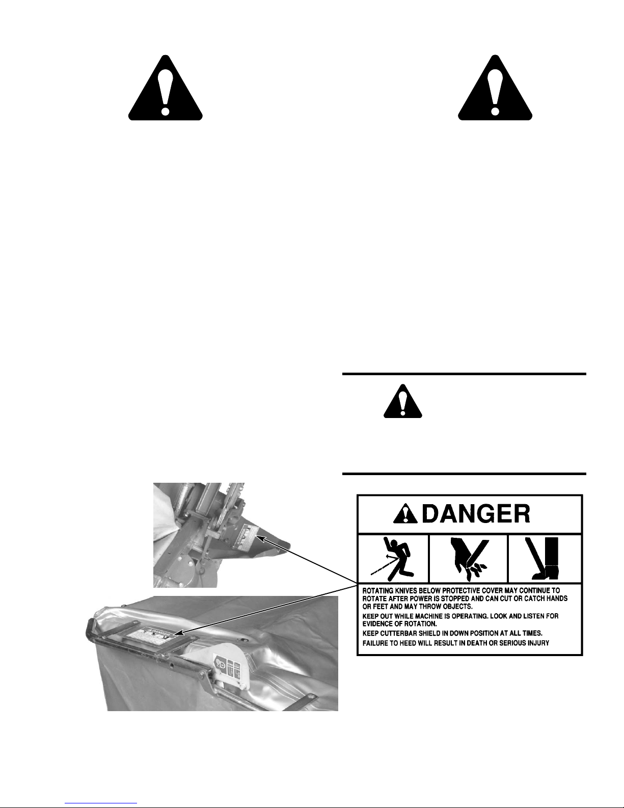
DANGER
‘‘DANGER’’ indicates an imminently hazardous situation which, if not avoided, will result
in death or serious injury.
MANDATORY SAFETY SHUTDOWN
PROCEDURE
Work of any type on machinery is always more
hazardous when the machine is in operation.
Therefore, unless expressly instructed to the
contrary, BEFORE unclogging, cleaning, adjusting, lubricating or servicing the machine,
the following MANDATORY SAFETY SHUTDOWN PROCEDURE should ALWAYS be followed:
BEFORE unclogging, cleaning, adjusting, lubricating or servicing the machine:
1. Disengage the tractor PTO.
2. Place the tractor transmission in park and/or
lock brake pedals to prevent tractor movement, then shut off the tractor engine. Lower
the machine until it is resting on firm ground.
3. Remove the tractor ignition key and take it
with you.
4. Wait for all movement to stop.
5. Remove the telescoping PTO drive.
ONLY when you have taken these precautions can
you be sure it is safe to proceed. Failure to follow the
above procedure could lead to death or serious
bodily injury!
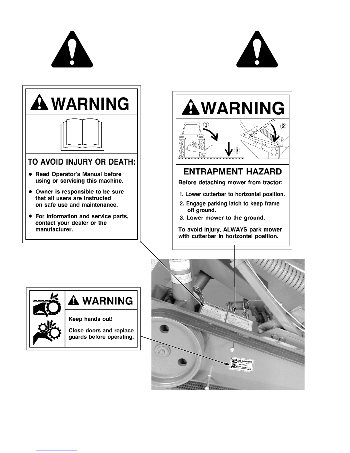
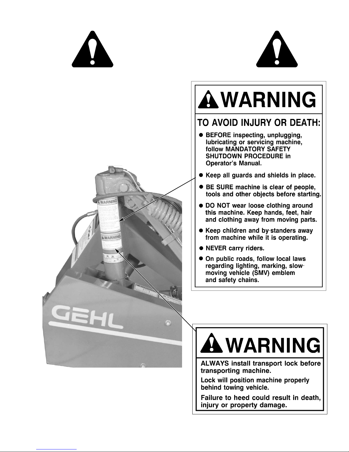
WARNING
‘‘WARNING’’ indicates a potentially hazardous situation which, if not avoided, could result in death or serious injury.
CAUTION
‘‘CAUTION’’ indicates a potentially hazardous
situation which, if not avoided, may result in
minor or moderate injury. May also alert
against unsafe practices.
909793/BP0805 8 Printed in U.S.A.
SAFETY REMINDERS
It is recommended that the towing tractor be equipped
with an enclosed operator’s cab with safety glass or
polycarbonate windows, or with protective mesh
screens.
Some photographs used in this manual may show doors,
guards and shields open or removed for illustration
purposes ONLY. BE SURE all doors, guards and shields
are in their proper operating positions and securely
attached BEFORE operating the machine.
ALWAYS wear safety glasses with side shields when
striking metal against metal. It is further recommended
that a softer (chip-resistant) material be used to cushion
the blow. Failure to follow these instructions could lead
to serious injury to the eyes or other parts of the body.
Page 11
SAFETY
(Continued)
BEFORE using the disc mower, inspect the cutting
knives, discs and attaching hardware. Do not straighten
bent knives — they must be replaced. Knives MUST be
replaced in pairs.
To ensure continued safe operation, replace damaged or
worn-out parts with genuine Gehl service parts, BEFORE operating the machine.
Regularly inspect the disc mower’s curtain. Replace the
curtain if it is worn or damaged. NEVER operate the
machine unless the protective curtain is in place and
folded down.
NEVER search for hydraulic fluid leaks using your bare
hands — use a piece of cardboard instead. Escaping
fluid under pressure can be invisible and can penetrate
skin and cause serious injury! If any fluid is injected into
the skin, see a doctor at once! Injected fluid MUST BE
surgically removed by a doctor familiar with this type of
injury or gangrene may result.
To avoid injury when changing from the “transport”
position to “operating” position, or “operating” to
“transport” position, BE SURE the immediate area is
clear of people and obstructions BEFORE changing
positions!
Fields to be mowed must be free of obstructions. Keep
people 50 feet (15 m) or more away from the machine
during operation. If an obstruction is encountered
during mowing, stop the unit immediately — follow the
MANDATORY SAFETY SHUTDOWN PROCEDURE! Check the entire disc mower before continuing
use.
DO NOT go near the machine until the discs have
stopped rotating! The mechanism can continue to
operate after the PTO is disengaged!
DO NOT attempt to hand feed or kick any crop or
material into the machine!
DO NOT attempt to mow crop in reverse!
DO NOT mow crop until you ARE SURE that the field
to be mowed is free of obstructions!
REMEMBER, it is the owner’s responsibility to com-
municate information about the safe use and proper
maintenance of the machine.
WARNING
DO NOT use the DM1162 or DM1165 Mower for
roadside cutting. DO NOT operate near
people.
Printed in U.S.A. 9 909793/BP0805
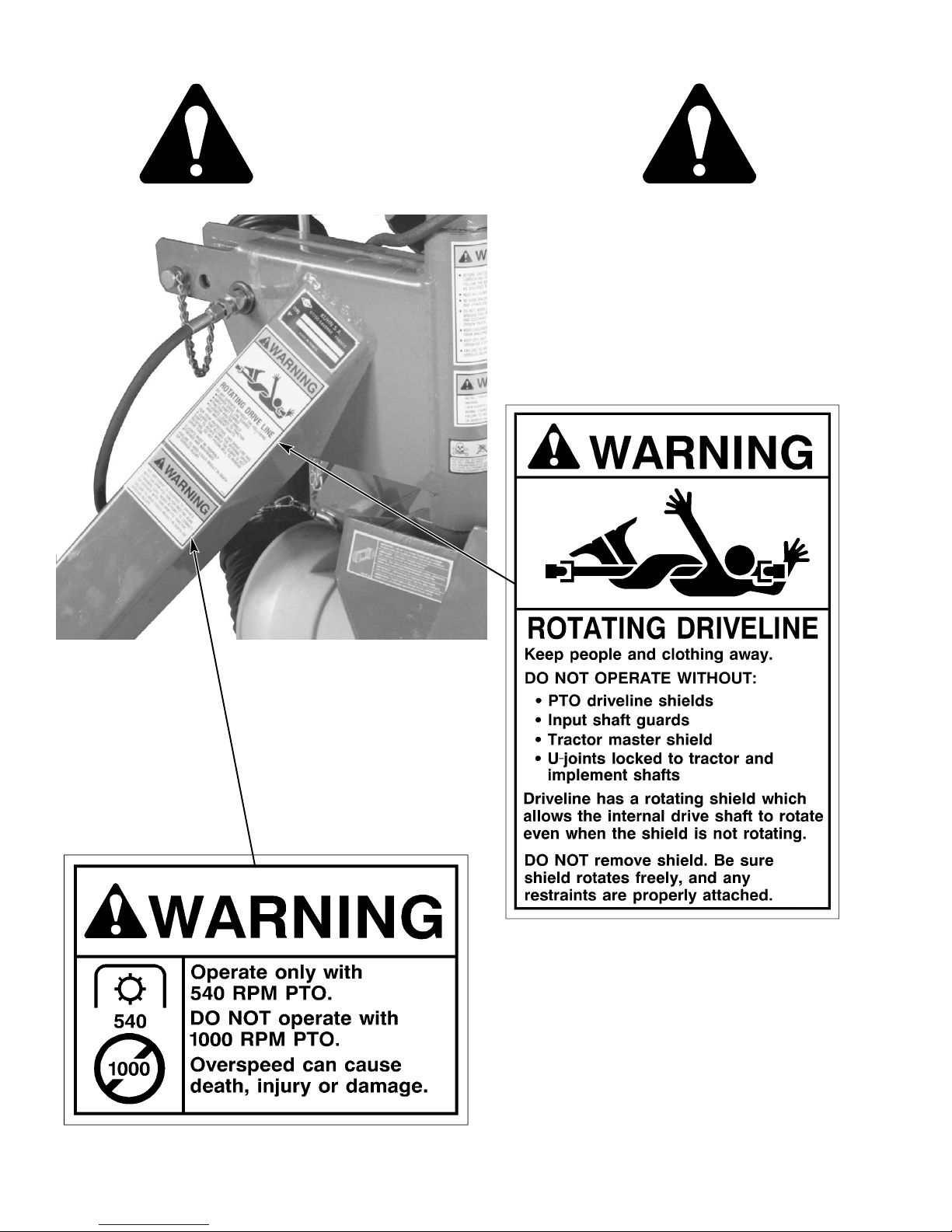
125476
Page 12
SAFETY
(Continued)
093367
163957
142375
909793/BP0805 10 Printed in U.S.A.
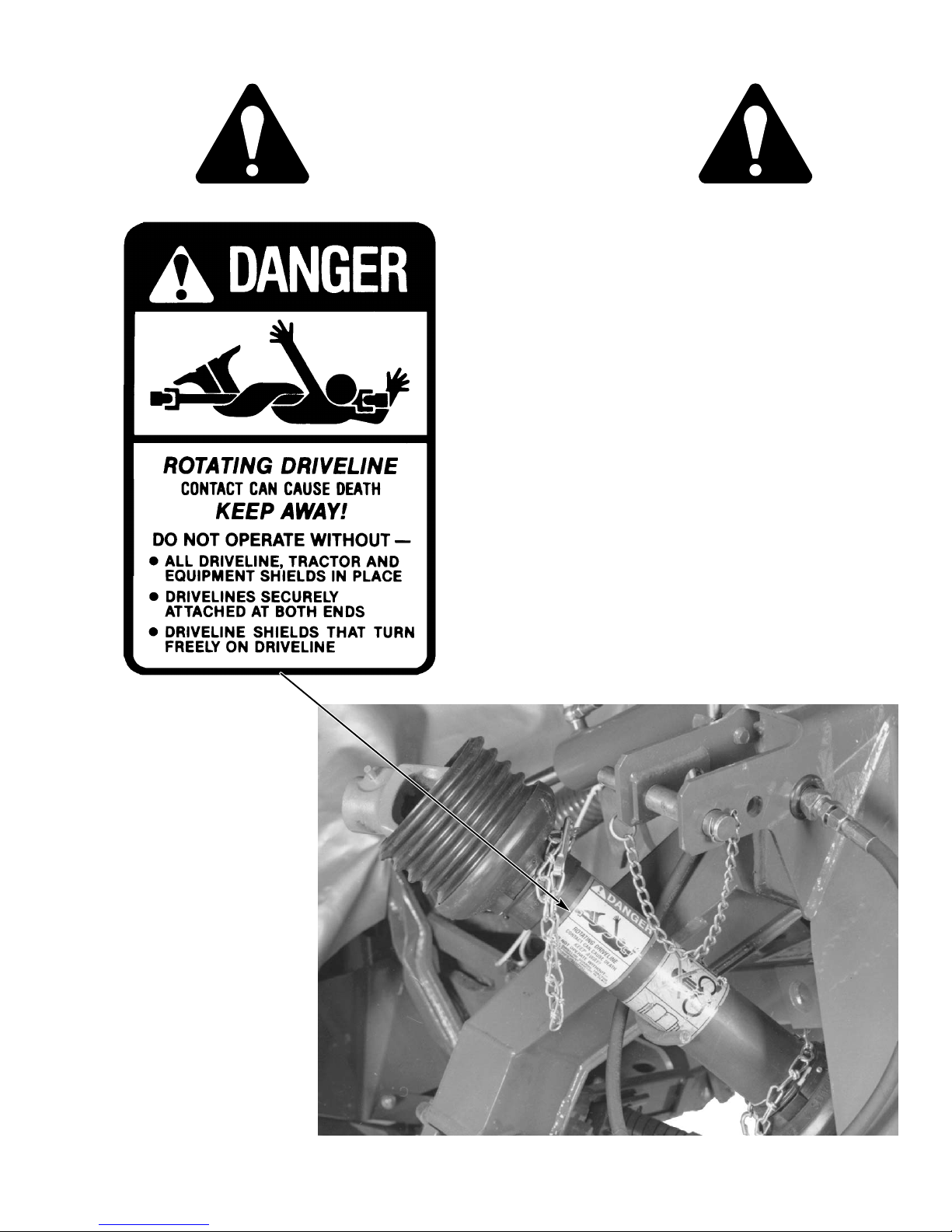
Page 13
SAFETY
(Continued)
Printed in U.S.A. 11 909793/BP0805
093373
093381
Page 14
SAFETY
(Continued)
909793/BP0805 12 Printed in U.S.A.
093653
093466
Page 15
SAFETY
(Continued)
091444
Printed in U.S.A. 13 909793/BP0805
Page 16
CHAPTER 5
CONTROLS & SAFETY EQUIPMENT
CAUTION
Become familiar with and know how to use
ALL safety devices and controls on the disc
mower BEFORE operating it. Know how to
stop disc mower operation before starting.
2
4
3
GUARDS, COVERS & SHIELDS
Where possible (without affecting machine operation),
guards, covers and shields are used to protect potentially
hazardous areas. In many places, decals are also
provided to warn of potential hazards as well as to
display special operating procedures.
WARNING
Read and observe ALL warnings on the machine BEFORE operating it. DO NOT operate
the machine unless ALL factory-installed
guards, covers and shields are in place and
properly secured.
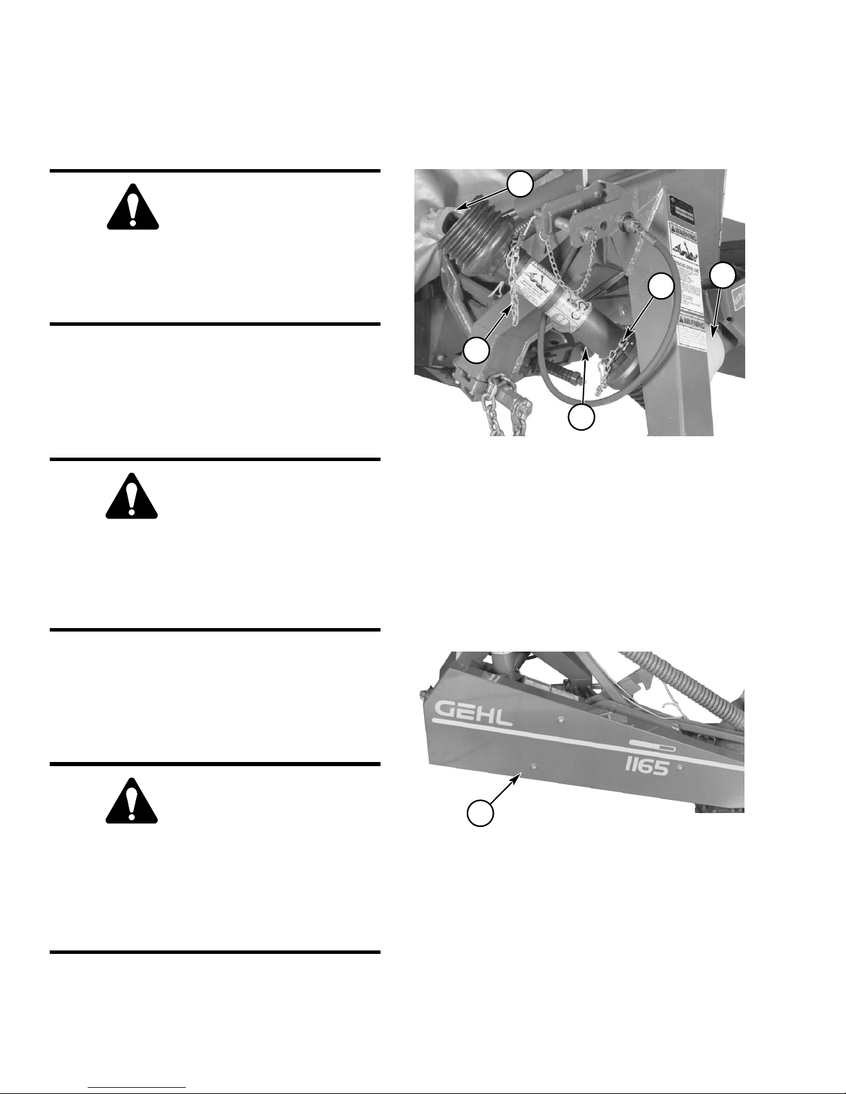
Drive Line Shields (Fig . 1)
The telescoping PTO drive, between the disc mower
input shaft and tractor PTO shaft, is equipped with guard
tubes which are held stationary by chains. Be sure the
front chain is attached to tractor and the rear chain is
attached to the disc mower.
3
1
1 - PTO Drive Shield
2 - PTO Drive Coupler
3 - PTO Guard Tube Chain (2 places)
4 - Disc Mower PTO Shield
Fig. 1: Telescoping PTO Driveline Shields
Belt Drive Cover (Fig. 2)
A cover is provided to protect and prevent contact with
the moving drive belts. Be sure the cover is in place and
tightly secured whenever the disc mower is in operation.
WARNING
BEFORE starting the tractor engine, BE SURE
the PTO is properly coupled to the tractor PTO
shaft and mower input shaft. Also, BE SURE
that the PTO guard tubes are properly chained
to the tractor PTO guard and disc mower to
prevent the tubes from turning.
909793/BP0805 14 Printed in U.S.A.
1
1 - Drive Belt Cover
Fig. 2
Page 17

1
2
1 - Protective Cover
2 - Cover Lock Mechanism (Also see Fig. 4)
Fig. 3: Protective Cover in Operating Position
(Folded Down)
Cutterbar Protective Cover (Fig. 3)
WARNING
Chapter 5 - Controls & Safety Equipment
To raise the cover and place it in the transport position:
1. Insert the handle-end of the special box wrench
(Fig. 4, Ref. 3) into the access hole (Fig. 4, Ref.
2). The special box wrench is provided with the
disc mower.
Be sure that the protective cover is in the operating position and properly secured BEFORE starting the tractor engine. The cover
will stop most debris and foreign objects that
might be propelled by the rotating knives and
discs below it, but it may not stop all such material. DO NOT operate near people. NEVER
operate the disc mower with the protective
cover in the raised position.
The protective cover (Fig. 3, Ref. 1) is designed to
contain MOST debris and foreign objects that could be
expelled by the rotating knives and discs below it. This
cover MUST ALWAYS be in the operating position
while the mower is running.
PROTECTIVE COVER LOCK
(Figs. 4 & 5)
The protective cover is provided with a lock (Fig. 4, Ref.
1) which automatically engages when the front half of
the cover is raised and folded over the rear half. This
locking feature secures the cover front half during
transport (when the cutterbar is raised into the vertical
position).
2. Push to release the lock while pulling up on the
cover front half as shown.
3. Fold the cover back until it locks into the transport
position.
1
3
2
1 - Protective Cover Lock Mechanism
2 - Release Access Hole
3 - Special Box Wrench
Fig. 4: Releasing Protective Cover Lock
to Place Cover into Transport Position
Printed in U.S.A. 15 909793/BP0805
Page 18

Chapter 5 - Controls & Safety Equipment
1
1 - Release Lever
Fig. 5: Releasing Protective Cover Lock
To lower the cover and place it in the operating position:
1. Lower the cutterbar into the operating position
(refer to the transport locks section later in this
chapter for proper procedure).
TRANSPORT & OPERATING
POSITION LOCKS (Fig. 6)
Stop lock (Ref. 1) - When in the operating position, this
lock is provided to prevent raising the cutterbar to the
transport position.
Transport hook- type lock (Ref. 2) - When the cutterbar
is moved into the transport position, this lock is
automatically engaged to prevent the cutterbar from
lowering.
Cylinder stroke limiter Lock (Ref. 5) - When in the
operating position and with the hydraulic control set to
“float” position, this lock prevents the cylinder rod
clevis from bottoming against the cylinder packing
gland.
All three of these locks are released by pulling on the
rope release mechanism (Ref. 4).
NOTE: Refer to the Transporting chapter for
proper procedures to place the cutterbar in the
transport and operating positions.
2. Use your fingers or the palm of your hand to apply
pressure on the lever (Fig. 5, Ref. 1) to release the
protective cover lock.
3. While applying pressure to the lever, fold the cover front half forward and down as shown.
4. Release the lever and continue to fold the cover
down until it locks into the operating position.
3
5
4
2
1
3
CAUTION
BEFORE transporting the disc mower on a
public highway or from one field to another,
BE SURE the transport hook lock is properly
engaged.
6
5
4
2
1
1 - Stop Lock
2 - Hook - type Transport Lock
3 - Rope Control Lift Points
Fig. 6: Transport & Operating Position Locks
909793/BP0805 16 Printed in U.S.A.
4 - Rope Control
5 - Cylinder Stroke Limiter
6 - Parking Lock
Page 19

Chapter 5 - Controls & Safety Equipment
PARKING LOCK (See Fig. 6)
The mower is equipped with a parking lock (Fig. 6, Ref.
6) which keeps the 3 - point hitch raised when the mower
is detached from the tractor.
NOTE: Refer to the Transporting chapter for
proper use of the parking lock.
BREAKAWAY LATCH (Fig. 7)
The mower is equipped with a breakaway latch and if an
obstruction is hit, the cutterbar must be free to swing
back. If the latch releases, stop the tractor immediately
and disengage the PTO. To reset the cutterbar, back the
mower until the cutterbar is in its normal position. DO
NOT raise the cutterbar to re-latch the breakaway.
Check for any cutterbar damage before resuming
operation after an obstruction is encountered.
1
2
3
4
IMPORTANT: Before using the mower, BE
SURE all sliding areas (Ref. 1) of the breakaway
latch mechanism are well greased and the
mechanism is operating properly.
Tension on the breakaway latch is determined by the
amount of compression on the spring washer stack (Ref.
3). The tension as set at the factory will be suitable for
most conditions. If the cutterbar continues to break
away, turn the adjustment bolt (Ref. 4) clockwise to
increase the breakaway pressure. (Refer to the Adjustments chapter for additional information.)
IMPORTANT: DO NOT overtighten the
adjustment bolt.
IMPORTANT: In rough field conditions, ground
speed should be reduced to protect the machine
from damage.
TELESCOPING DRIVE COUPLER
(See Fig. 1)
The telescoping drive is equipped with spring-loaded
locking devices to positively lock it onto the tractor PTO
shaft and the disc mower input shaft. Depress the
locking device against the spring tension and slide the
yoke onto the tractor PTO shaft. Release the locking
device and move the yoke ahead or back until the lock
engages into the groove of the PTO shaft. The same
process is used to install the other end of the telescoping
drive line to the disc mower input shaft.
1 - Sliding Area
2 - Latch Mechanism in “Latched” Position
3 - Spring Washer Stack
4 - Adjustment Bolt
Fig. 7: Breakaway Latch
Printed in U.S.A. 17 909793/BP0805
Page 20

CHAPTER 6
OPERATION
FIRST TIME OPERATION
WARNING
If this is the first time you are using the machine, DO NOT start, operate or service it until
you have read and understand the contents of
this manual.
NORMAL OPERATION
CAUTION
BEFORE operating the disc mower, review
and comply with ALL SAFETY recommendations set forth in the SAFETY chapter of this
manual.
WARNING
DO NOT use the DM1162 or DM1165 mower for
roadside cutting. DO NOT operate near
people.
START- UP
WARNING
BE SURE ALL factory- installed guards and
shields are in place and properly secured BEFORE starting the tractor engine. DO NOT operate near people. The protective cover will
contain most debris and foreign objects but
may NOT stop all such material.
When changing the cutterbar from the transport to the
normal operating position and BEFORE engaging the
PTO, ALWAYS allow several minutes for the oil in the
cutterbar to spread. To avoid unnecessary strain on the
disc mower components, ALWAYS engage the tractor
PTO slowly and with the tractor engine at less than half
throttle. Bring the unit to PTO speed BEFORE starting
to cut.
IMPORTANT: Always operate the mower at 540
rpm PTO speed! Operating above 540 rpm could
cause excessive vibration, wear and possible
component failure. Operating the unit below 540
rpm will increase the chances of plugging.
UNPLUGGING
EMERGENCY SHUTDOWN
If crop material is clogging the cutterbar or a foreign
object enters the cutting area, STOP cutting material
IMMEDIATELY by disengaging the tractor PTO and
stopping forward movement. Then, exercise the MANDATORY SAFETY SHUTDOWN PROCEDURE
(page 8) BEFORE leaving the tractor seat to remedy the
problem.
GROUND SPEED
The disc mower can be operated in a wide range of
ground speeds depending on crop conditions and
terrain. Any change in ground speed should be made by
changing tractor gears and NOT by increasing or
decreasing tractor engine RPM.
909793/BP0805 18 Printed in U.S.A.
In certain crop conditions, it is possible for the disc
mower to plug. When plugging occurs, the drive belts
will slip.
To clear a plugging condition in the area of the discs:
1. Disengage the PTO.
2. Raise the mower several inches.
3. Exercise the MANDATORY SAFETY SHUTDOWN PROCEDURE (page 8) and apply the
tractor parking brake.
4. Carefully clear the plug from the cutterbar area.
If the plugging occurs frequently, refer to the Troubleshooting chapter for additional directives.
Page 21

Chapter 6 - Operation
ADVERSE FIELD CONDITIONS
WARNING
Use extra caution in fields that may contain
rocks. Use a slower ground speed and tilt cutterbar back towards horizontal. Use of optional v-type knives should be considered.
Extra care and precautions should be taken when
working in rough or difficult terrain. To minimize the
possibility of foreign objects being deflected by the
cutterbar blades, the following adjustments should be
made when operating in adverse field conditions:
1. Adjust the top link (Ref. 1) of the tractor 3-point
hitch to tilt the cutterbar back towards horizontal
and raise the cutting height of the knives.
IMPORTANT: NEVER tilt the cutterbar back past
horizontal as this will lead to premature blade wear.
2. Use a slower ground speed.
3. Be sure the cutting knives can pivot if an obstruction is hit.
1
2
1 - Tractor 3- Point Hitch Top Link
2 - Cutterbar in Horizontal Position
(Maximum Cutting Height - Result when Top
Link is Shorter)
3 - Cutterbar Tilted Forward
(Normal Cutting Height - Result when Top Link
is Longer)
Fig. 8: Cutting Height Adjustment
3
Printed in U.S.A. 19 909793/BP0805
Page 22

CHAPTER 7
ADJUSTMENTS
The DM1162 and DM1165 disc mowers have been
designed and factory adjusted to function properly
under most field operating conditions. However, due to
the wide range of operating conditions that could be
encountered, additional adjustments may be required.
WARNING
BEFORE adjusting the disc mower, exercise
the MANDATORY SAFETY SHUTDOWN PROCEDURE (page 8).
4
CUTTING HEIGHT ADJUSTMENT
(Fig. 9)
The cutting height can be changed by tilting the
cutterbar. To tilt the cutterbar, turn the tractor top link on
the 3-point hitch until the desired cutting height is
obtained.
IMPORTANT: If the field being cut is very uneven
or may contain rocks, reduce the cutting angle and
gound speed. Cutting too close to the ground will
cause excessive wear on the cutterbar discs and
knives. In down, tangled and lodged crops, use a
steeper disc angle to obtain a clean cut.
1
1 - 2” (50 mm) Maximum Cutting Height
2 - 1-1/4” (30 mm) Minimum Cutting Height
Fig. 9: Cutting Height Adjustment
3
2
3 - 3-Point Hitch Top Link
4 - Disc Mower Frame
909793/BP0805 20 Printed in U.S.A.
Page 23

DRIVE BELT TENSION (Fig. 10)
The belts MUST be properly tensioned at all times to
prevent slipping. Loose belts will wear out faster and
cause poor cutting.
To tighten the belts:
Use the 18 mm box wrench (Ref. 1 - provided with the
mower) to turn the adjustment bolt until the spacer tube
(Ref. 2) is in contact with the main frame (Ref. 3) and
the washer (Ref. 4).
Chapter 7 - Adjustments
1
NOTE: During initial assembly and when fitting
new V-belts, give two additional complete turns on
the adjustment bolt.
IMPORTANT: It is very important that the belt
tension be checked and adjusted properly,
especially after the first few hours of use. Replace
belts ONLY as a complete set. If one of them
becomes damaged, the whole set must be
replaced.
3
2
1
2
3
4
1 - Sliding Area
2 - Latch Mechanism in “Latched” Position
3 - Spring Washer Stack
4 - Adjustment Nut
Fig. 11: Breakaway Latch
Tension Adjustment
Tension on the breakaway latch is determined by the
length of the spring washer stack (Fig. 12, Ref. 1). The
tension as set at the factory [3-3/4 in. (95 mm)] will be
suitable for most conditions. If the cutterbar continues
to break away, turn the adjustment nut (Fig. 11, Ref. 4)
clockwise to increase the breakaway pressure.
IMPORTANT: The length of the spring stack
(Fig. 11, Ref. 1) MUST NOT be less than 3-9/16 in.
(91 mm).
BE SURE that the spring washers are stacked as shown
in Fig. 12.
2
4
1 - 18 mm Box Wrench
2 - Spacer Tube
3 - Main Frame
4 - Washer
Fig. 10: Drive Belt Tension Adjustment
BREAKAWAY LATCH TENSION
ADJUSTMENT (Figs. 11 & 12)
IMPORTANT: BE SURE all sliding areas (Fig.
11, Ref. 1) of the breakaway latch mechanism are
well greased and the mechanism is operating
properly.
Printed in U.S.A. 21 909793/BP0805
1
1 - Factory Setting 3 - 3/4” (95mm)
2 - Spring Washer Stack
Fig. 12: Breakaway Latch Spring Washer
Stack Detail
Page 24

Chapter 7 - Adjustments
GROUND PRESSURE
ADJUSTMENT (Fig. 13)
The amount of tension on the compensating spring (Ref.
1) determines the mower ground pressure. The ground
pressure can be increased or decreased by making the
distance (Ref. 2) between the lock nut (Ref. 3) and the
center of the anchor pin longer or shorter, respectively.
The distance as set at the factory [3-1/2” (90 mm)] will
be suitable for most conditions.
When the terrain is rough and less ground pressure is
desired, adjust the compensating spring tension as
follows:
1. Raise the cutterbar until the compensating spring
is slack.
2. Loosen the lock nut.
3. Turn the compensating spring to make the lock
nut-to-anchor pin distance (Ref. 2) shorter
4. After making the adjustment, tighten the lock nut.
.
3
2
1
1 - Compensating Spring
2 - Distance - Lock Nut -toAnchor Pin Center
[Factory Setting for Normal Ground Pressure
is 3-1/2 in. (90 mm)]
3 - Lock Nut
Fig. 13: Ground Pressure Adjustment
909793/BP0805 22 Printed in U.S.A.
Page 25

Notes
Chapter 7 - Adjustments
Printed in U.S.A. 23 909793/BP0805
Page 26

CHAPTER 8
LUBRICATION
GENERAL INFORMATION
WARNING
NEVER attempt to lubricate the machine when
any part of the unit is in motion. ALWAYS BE
SURE to exercise the MANDATORY SAFETY
SHUTDOWN PROCEDURE (page 8), BEFORE
lubricating the machine.
Proper lubrication of the disc mower will prevent
excessive part wear and early failure.
IMPORTANT: Whenever service is performed
on hydraulic components (valves, cylinders,
hoses, etc.) or transmission, care must be taken
to prevent discharging fluid onto the ground.
Catch and dispose of fluid according to
environmental law.
BEVEL GEARBOX (Fig. 14)
A plug (Ref. 1) is provided for checking the oil level in
the gearbox when the cutterbar is in the horizonal
position. This plug is also used as a gearbox drain when
the cutterbar is in the vertical transport position. The oil
should be changed every 200 hours of operation or
annually (more often if operated under heavy loads). An
oil fill plug (Ref. 2) is provided on the top of the gearbox
for adding or changing oil. The gearbox holds 0.5 U.S.
qts. (0.45 L). Use SAE 80W90 GL5 EP oil.
A pressure relief valve (Ref. 3) is located on the side of
the gearbox and must be removed and cleaned each time
the gearbox oil is changed. BE SURE that the ball detent
moves freely to relieve pressure.
The gearbox should be checked occasionally for oil
drips and dust accumulation around the seals. Oil drips
or dust accumulation indicate that seals are leaking. Oil
which is tan in color and foams excessively indicates
that it has water present.
IMPORTANT: The oil in the gearbox MUST be
changed after the first 10 hours of operation. BE
SURE to also clean and check the pressure relief
valve at this time.
2
1
3
1 - Check Oil Level & Drain Plug
2 - Oil Fill Plug
3 - Pressure Relief Valve
Fig. 14: Gearbox Lubrication Detail
CUTTERBAR (Fig. 15)
To check the oil in the cutterbar, park the tractor on level
ground and place the cutterbar in the vertical transport
position. A plug (Ref. 1) is provided for checking the oil
level in the cutterbar. The oil level is correct when the
oil just begins to flow out of the hole. The oil should be
changed every 200 hours or annually (more often if
operated under heavy loads). The following procedure
MUST be followed:
1. Operate the disc mower for 10 minutes so that the
cutterbar reaches operating temperature.
2. Raise the disc mower to the vertical transport position and be sure the transport lock is engaged.
3. Exercise the MANDATORY SAFETY SHUTDOWN PROCEDURE (page 8).
4. Remove the magnetic drain plug (Ref. 2) and the
oil level/fill plug, allowing the oil to drain completely. Wait for the dripping to stop.
5. BE SURE to clean the magnetic drain plug thoroughly before installation.
6. Refill the cutterbar with SAE 80W90 GL5 oil.
The cutterbar holds 2.1 U.S. qts. (2 L). and reinstall the oil level/fill plug.
909793/BP0805 24 Printed in U.S.A.
Page 27

Chapter 8 - Lubrication
IMPORTANT: The oil in the cutterbar MUST be
changed after the first 10 hours of operation.
The cutterbar should be checked daily for oil drips and
dust accumulation around the seals. Oil drips or dust
accumulation indicate that seals are leaking. Oil which
is tan in color and foams excessively indicates that it has
water present.
NOTE: There will be signs of oil at the overflow
plug. A small amount of oil in this location should
be considered normal.
IMPORTANT: If the cutterbar is to be operated at
angles in excess of ± 20° from horizontal for long
periods of time, the quantity of cutterbar oil should
be reduced by 25%. If the quantity of oil is reduced,
the cutterbar MUST be operated in a horizontal
position for a few minutes every 1/2 hour.
1
GREASING
IMPORTANT: Grease all fittings at the intervals
listed, before and after storage, and as noted. Use
a good grade of lithium- based grease.
Wipe dirt from the fittings BEFORE greasing to prevent
any dirt from being forced into the fittings. Replace any
missing fittings, when noted. To minimize dirt build-up,
avoid excessive greasing.
Grease Fitting Locations (Fig. 16)
Grease Every 8 hours (or Daily)
1. Telescoping PTO drive crosses (2 places)
2. Overrunning clutch
Grease Every 20 hours (or twice
Weekly)
3. Inner telescoping PTO section
Grease Every 40 hours (or Weekly)
2
1 - Check Oil Level & Fill Plug (Cutterbar Vertical)
2 - Magnetic Drain Plug
Fig. 15: Cutterbar Lubrication Detail
SEALED BEARINGS
Sealed bearings are used throughout the disc mower to
provide trouble-free operation. These bearings are
sealed and lubricated for life. Relubrication is NOT
required, NOR should it be attempted.
OILING
4. Telescoping PTO guards (2 places)
5. Spring loaded PTO locking coupler
Grease as Required
6. Grease the inside of the outer guard tube in winter
to prevent freezing.
7. All break-away components
1
5
4
3
4
2
5
1
Oil all linkage and pivot points every 50 hours of
operation using a good grade of motor oil.
Printed in U.S.A. 25 909793/BP0805
Fig. 16: PTO Grease Fitting Locations
Page 28

CHAPTER 9
SERVICE
GENERAL INFORMATION
WARNING
BEFORE servicing the disc mower, exercise
the MANDATORY SAFETY SHUTDOWN PROCEDURE (page 8).
NOTE: All services, detailed in this chapter are
owner/operator responsibilities. Where indicated,
certain service routines should only be carried out
by (or under the direction of) an authorized Gehl
equipment dealer.
CUTTERBAR
All service to the internal parts of the cutterbar MUST
be carried out by (or under the direction of) an
authorized Gehl equipment dealer.
DISCS, KNIVES AND HARDWARE
Discs, knives, bolts and nuts are fabricated from high
quality steel and undergo a special heat treatment
process to ensure a tough wear resistance and longer
life.
Knife Hardware (Fig. 17)
If any of the following conditions exist, the knife
retaining hardware MUST be replaced. See Fig. 17 for
details.
1. When a visible deformation is found.
2. When the locking compound on the bolt threads
has worn away or if the locking compound has
become inoperative due to contamination by
water, oil or dirt.
3. When a wear groove deeper than 1/8” (3mm) has
formed on the bearing shoulder of the knife bolt
(Ref. 2).
4. When wear on the bolt head reaches the contact
area of the knife (Ref. 3).
5. When the contact washer of the knife retaining nut
has lost its elasticity or the washer becomes loose
from the nut (Ref. 5).
6. When wear on the nut reaches a depth equal to half
the height of the nut (Ref. 6).
7. When the retaining hardware has been removed 5
times.
WARNING
To avoid creating hazardous out-of-balance
forces, ALWAYS replace missing, damaged or
worn knives and hardware in pairs!
IMPORTANT: Worn or damaged items MUST be
replaced immediately with genuine GEHL service
parts, otherwise the warranty is void.
WARNING
Use ONLY genuine GEHL service parts.
909793/BP0805 26 Printed in U.S.A.
1
4
1 - Acceptable Bolt with Locking Compound Intact
2 - Unacceptable Bolt with Wear Groove
3 - Unacceptable Bolt with Edge Wear
4 - Acceptable Nut with Contact Washer
5 - Unacceptable Nut with Contact Washer Crushed
6 - Unacceptable Nut with Edge Wear
2
5
Fig. 17
3
6
Page 29

Chapter 9 - Service
Knife Removal & Replacement
(See Fig. 18)
Knives should be inspected systematically each time
before the disc mower is operated. Failure to replace
knives as required will result in an increase in the risk
of accidents, a deterioration in the quality of cut and
a risk of damage to the cutterbar. Both knives on each
disc MUST be replaced in pairs to maintain balance
if any of the following conditions exist:
1. If any sign of cracking is found.
2. Refer to Fig. 18. The width of a knife (Ref. 2),
measured at a distance of 3/8” (10 mm) away from
the edge of the disc (Ref. 1), MUST be greater
1-3/8” (34 mm).
3. The hole in the knife for the retaining bolt MUST
NOT be worn oval by more than 1/16” (2 mm).
See Fig. 18, Ref. 3.
1
2
than
When replacing a knife (knives MUST BE replaced in
sets) on the disc mower, the following steps MUST be
followed:
1. Clean around the self-locking nut to be removed.
2. Position the disc to allow the knife retaining bolt
to drop through the access hole in the front, center
of the skid shoe.
3. Remove the self-locking nut with the box wrench
provided with the disc mower (or an 18 mm socket).
4. Fit a new knife or turn the worn knife over to use
second cutting edge. BE SURE that the knife is
positioned with the small arrow pointing in the direction of rotation of the corresponding disc.
5. BE SURE the bolt is in good condition BEFORE
reusing.
6. Torque locknuts to 90 ft.-lbs. (120 Nm).
WARNING
Use ONLY genuine Gehl service parts.
3
1 - 3/8” (10 mm)
2 - 1-3/8” (34 mm)
3 - Maximum Out-of-round 1/16” (2 mm)
Fig. 18
IMPORTANT: To ensure proper knife retention,
the retaining hardware MUST be replaced after
having been removed five times.
WARNING
ALWAYS replace damaged knives in pairs.
NEVER attempt to straighten a bent knife or
replace a single knife.
Printed in U.S.A. 27 909793/BP0805
Page 30

Chapter 9 - Service
Disc Removal & Replacement
(Figs. 19, 20 & 21)
NOTE: Place a block of wood between the discs
so the discs will NOT rotate when removing the
mounting hardware.
Left Disc
1. Remove four self-locking cap screws (Fig. 21,
Ref. 1) to remove the flat cover (Ref. 2).
2. Remove four each cap screws (Ref. 3) and conical
spring washers (Ref. 4).
3. Remove the left disc assembly (Ref. 5); if the disc
is tight, pry up with two levers at opposite sides of
the disc.
4. The spacer (Ref. 6) is only used if the clearance
between the knife mounting bolt head and the cutterbar guard is less than 1/32” (1 mm). Refer to
Fig. 19 for measurement details.
5. Position the new disc and spacer, if required, on
the cutterbar hub. BE SURE the disc is rotated 90°
from the adjacent disc and that each knife is positioned with the small arrow pointing in the direction of disc rotation. Secure the disc with four each
cap screws and conical spring washers. Tighten
the cap screws to 90 ft.-lbs. (120 Nm) torque.
IMPORTANT: BE SURE the conical spring
washers are positioned with the crown up as
shown in Fig. 20.
6. Install the flat cover (Ref. 2) using four self-locking cap screws (Ref. 1). Tighten the cap screws to
65 ft.-lbs. (85 Nm) torque.
1
1 - Conical Spring Washer
Fig. 20
Right Disc
1. Remove four self-locking cap screws (Fig. 21,
Ref. 1) to remove the curved cover (Ref. 9).
2. Remove four each cap screws (Ref. 3) and conical
spring washers (Ref. 4).
3. Remove the right disc assembly (Ref. 10). If the
disc is tight, pry up with two levers at opposite
sides of the disc.
4. The spacer (Ref. 6) is only used if the clearance
between the knife mounting bolt head and the cutterbar guard is less than 1/32” (1 mm). Refer to
Fig. 19 for measurement details.
5. Position the new disc and spacer, if required, on
the cutterbar hub. BE SURE the disc is rotated 90°
from the adjacent disc and that each knife is positioned with the small arrow pointing in the direction of disc rotation. Secure the disc with four each
cap screws and conical spring washers. Tighten
the cap screws to 90 ft.-lbs. (120 Nm) torque.
IMPORTANT: BE SURE the conical spring
washers are positioned with the crown up as
shown in Fig. 20.
6. Install the curved cover (Ref. 9) using four selflocking cap screws (Ref. 1). Tighten the cap
screws to 65 ft.-lbs. (85 Nm) torque
1
1 - 1/32 in. (1 mm) Minimum Clearance
Fig. 19
909793/BP0805 28 Printed in U.S.A.
Flat (Intermediate) Discs
1. Remove two cap screws (Fig. 21, Ref. 3) and conical spring washers (Ref. 4) to remove the conical
cover (Ref. 7).
2. Remove the remaining two cap screws (Ref. 3)
and conical spring washers (Ref. 4) to remove the
disc (Ref. 8). If the disc is tight, pry up with two
levers at opposite sides of the disc.
3. The spacer (Ref. 6) is only used if the clearance
between the knife mounting bolt head and the cutterbar guard is less than 1/32” (1 mm). Refer to
Fig. 19 for measurement details.
Page 31

Chapter 9 - Service
4. Position the new disc and spacer, if required, on
the cutterbar hub. BE SURE the disc is rotated 90°
from the adjacent disc and that each knife is positioned with the small arrow pointing in the direction of disc rotation.
5. Secure the disc with two cap screws and conical
spring washers. Torque the cap screws to 90 ft.lbs. (120 Nm).
2
1
3
IMPORTANT: BE SURE the conical spring
washers are positioned with the crown up as
shown in Fig. 20.
6. Install the conical cover (Ref. 7) using two cap
screws and conical spring washers. Torque the cap
screws to 90 ft.-lbs. (120 Nm).
9
10
7
8
4
5
6
1 - Self-locking Cap Screw (8 used each model)
2 - Flat Cover
3 - Cap Screw (24 used on DM1162, 28 used on DM1165)
4 - Conical Spring Washer
(24 used on DM1162, 28 used on DM1165)
5 - Left Disc Assembly
6 - 1/32″ (1 mm) Spacer
Fig. 21: Disc Replacement (DM1165 Shown)
11
7 - Conical Cover (4 used on DM1162, 5 used on DM1165)
8 - Flat Disc (4 used on DM1162, 5 used on DM1165)
9 - Curved Cover
10 - Right Disc Assembly
11 - Cutterbar Assembly (Reference)
TELESCOPING DRIVES
IMPORTANT: For safety reasons, service on the
telescoping PTO drives should ONLY be
performed by (or under the direction of) an
authorized Gehl equipment dealer.
Printed in U.S.A. 29 909793/BP0805
Over time, the telescoping drive universal joints may
become worn and noisy and require service. As
necessary, remove the drive(s) from the disc mower and
take them to your dealer.
Page 32

CHAPTER 10
PREPARING FOR FIELD OPERATION
TRACTOR REQUIREMENTS
The tractor used to operate the disc mower MUST have:
1. A 540 RPM PTO.
2. A minimum power rating of 42 hp (30 kW) for the
DM1162 and 50 hp (36 kW) for the DM1165.
3. A Category II 3-point hitch.
4. One remote hydraulic output capable of powering
a single-acting cylinder.
5. The tractor should be equipped with a cab.
ADAPTING MOWER TO TRACTOR
The disc mower is provided with adjustable hitch pins
to accommodate various tractor sizes and rear wheel
spacing arrangements.
Refer to Figs. 22 & 23. The mower must be positioned
so that the inside cutting path of the left disc (Ref. 2) is
approximately 2″ (50 mm) to the right of the outside of
the right tractor tire (see Ref. 1). If necessary, loosen the
four cap screws (Fig. 22, Ref. 2) at each lower hitch pin
(Ref. 4) mounting location to slide the mower 3-point
frame left or right. Be sure the distance (Ref. 3) is
maintained. After the correct position is obtained,
tighten the eight cap screws (Ref. 2) to 90 ft.-lbs. (120
Nm) torque.
NOTE: The stop chain (Fig. 22, Ref. 4) is pro-
vided with the mower. This chain is used only when
the tractor IS NOT equipped with 3-point hitch hydraulic positioning control. (Refer to the “Setting
Mower Frame Working Height” topic later in this
chapter.)
1
3
3
2
4
1 - Mower 3-point Hitch Frame
2 - Cap Screw (4 used for each Hitch Pin)
3 - Lower Hitch Pins
4 - Stop Chain (see NOTE, above)
2
Fig. 22
4
1 - 2″ (50 mm)
2 - Cutting Path of Left Disc Assembly
Fig. 23: Mower- to - Tractor Position
909793/BP0805 30 Printed in U.S.A.
1
3
2
4
3 - 32-1/2″ (825 mm)
4 - Lower Hitch Pin (2 used)
Page 33

ATTACHING MOWER TO TRACTOR
1. Clean all paint from the hitch pins.
2. Refer to Fig. 24. Back the tractor to the mower and
attach the lower links to the hitch pins. Secure
links with lynch pins (Ref. 1) provided.
2
3
Chapter 10 - Preparing For Field Operation
1
2
1 - Retainer
2 - Parking Lock
Fig. 25
SETTING MOWER FRAME
WORKING HEIGHT
1
1 - Lynch Pins
2 - Tractor Top Link
3 - Top Link Pin
Fig. 24: Connecting Mower to Tractor
3. Attach the top link to the mower. Secure the link
with the pin provided. Two positions are available
to install the top link retaining pin, depending on
the diameter of the top link ball joint.
4. Connect the hydraulic lift cylinder hose to the
tractor.
5. Raise the mower with the tractor 3-point hitch
system. Fold the mower parking lock (Ref. 2) upward (see arrow) until it engages in the retainer
(Ref. 1). Raise the cutterbar in and out of the transport position several times to purge the air out of
the hydraulic system.
IMPORTANT: ALWAYS position the parking lock
in the upper position while transporting or
operating the disc mower.
For Tractors Equipped with Hydraulic
Position Control of 3-Point Hitch
Refer to Fig. 26. On level ground, adjust the mower with
the tractor hydraulic 3-point lift system so that the
centers of the lower hitch pins are at a height of 15″ (420
mm) from the ground, as shown.
1
2
1 - Center of Lower Hitch Pin
2 - Adjustment Height of 15″ (420 mm)
Fig. 26
Printed in U.S.A. 31 909793/BP0805
Page 34

Chapter 10 - Preparing For Field Operation
For Tractors without 3-Point Hitch
Hydraulic Position Control
Refer to Fig. 27.
1. On level ground, adjust the mower with the tractor
3-point lift system so that the centers of the lower
hitch pins are at a height of 15″ (420 mm) as
shown.
2. Attach the chain to the tractor clevis (or to an
available hole in the tractor top link) with the
chain hook.
3
1
2
1 - Center of Lower Hitch Pin
2 - Adjustment Height of 15″ (420 mm)
3 - Chain
Fig. 27
3. Lower the mower into the working position. the
height adjustment is correct when:
a. the cutterbar is resting on the ground.
b. the chain is tight.
c. the distance between the hitch pins and the
ground is 15″ (420 mm).
NOTE: Use a hairpin cotter to attach the sur-
plus end of the chain to the used portion.
PTO SHAFT
Before the PTO is connected to the tractor, the PTO
driveline MUST be sized.
IMPORTANT: When the PTO driveline is in its
maximum extended position, the drive tubes
MUST overlap a minimum of 10″ (250 mm). Also,
the PTO MUST BE short enough to prevent
bottoming out (see the PTO sizing section, below).
Failure to properly size the PTO WILL result in
premature failure.
PTO Sizing (Fig. 28)
1. Separate the two PTO half shafts. Connect the end
with the free-wheeling hub to the disc mower input shaft (Ref. 2) and the other half to the tractor
PTO (Ref. 1). BE SURE both ends lock in place.
2. Raise or lower the mower to find the position
where the PTO shaft would be in its shortest position.
3. Hold the tractor half of the PTO next to the mower
half.
4. When the PTO is in its maximum retracted position, a 3/8″ (10 mm) gap (Ref. 5) MUST exist be-
tween the end of the tractor-half drive tube (Ref.
7) and the mower-half PTO yoke (Ref. 6). If the
gap is less then specified, shorten both PTO drive
tubes and both guard tubes as follows:
a. Mark off the total length to remove (Ref. A)
so that there is a 3/8″ (10 mm) gap between
the end of the tractor-half PTO drive tube
and the mower-half PTO yoke (shown as
Refs. 5, 6 & 7).
b. Divide the total amount to be removed by
two - so that the same amount will be removed from each PTO half. The result is
Ref. B.
c. Cut off equal amounts (Ref. B) from the
ends of both guard tubes and both drive
tubes.
Remove the sharp edges from the cut tubes and clean out
all chips and filings. Apply grease to the inside of the
outer telescoping tube.
Assemble the two PTO half shafts and connect the
complete PTO assembly to the tractor PTO and the disc
mower input shaft. BE SURE to connect the free end of
the safety chains to a fixed point on the tractor and disc
mower.
909793/BP0805 32 Printed in U.S.A.
Page 35

Chapter 10 - Preparing For Field Operation
1
B
1 - Tractor PTO Shaft
2 - Disc Mower Input Shaft
3 - Guard Tube
4 - Tractor-half Drive Tube
5 - 3/8″ (10mm) Gap
4
3
Fig. 28: Sizing the PTO
3
A
2
4
7
5
6
6 - Mower-half PTO Yoke
7 - Desired Location of Tractor-half Drive Tube
when PTO is Fully Retracted
A - Total Length to Cut Off
B - Cut Off Locations (One - half of “A”)
WARNING
BEFORE operating the disc mower, BE SURE
that the PTO driveline shields are properly
chained to the tractor PTO guard and disc
mower to prevent them from turning.
NOTE: The angle of the Telescoping PTO
MUST NOT exceed 30°. BE SURE to also disen-
gage the PTO when the tractor 3- point hitch is
raised to the maximum height.
BREAK- IN
Before starting to cut, it is recommended that the disc
mower be broken in by running it empty for approximately 30 minutes. This initial run-in MUST be done
with the cutterbar in the cutting position.
The break-in should consist of a 25 minute low-speed,
and a 5 minute high-speed, run-in period. First, run the
machine for 25 minutes with the tractor engine close to
idle RPM. Next, stop the machine and exercise the
MANDATORY SAFETY SHUTDOWN PROCEDURE (page 8) before leaving the tractor seat to inspect
the disc mower. After inspection is complete, reconnect
the PTO, restart the tractor, engage the PTO near engine
idle speed and gradually increase the speed to proper
operating RPM and continue running the machine for 5
minutes. After another inspection, the disc mower is
ready for use.
IMPORTANT: The oil in the cutterbar and the
gearbox MUST be changed after 10 hours of
operation. For details, see the Lubrication chapter.
NOTE: The drive belts MUST be adjusted after
10 hours of operation. For details, see the Adjustments chapter.
TRANSPORTING
BEFORE transporting the disc mower, refer to the
Transporting chapter for transporting information.
Printed in U.S.A. 33 909793/BP0805
Page 36

CHAPTER 11
TRANSPORTING
TRANSPORT LOCK
To transport the mower on the highway or from one field
to another, proceed as follows:
1. Disengage the PTO drive and wait for all movement to stop.
2. Raise the mower off the ground with the tractor
3-point hitch system.
3. Refer to Fig. 29. Use the handle-end of the box
wrench (Ref. 3) provided with the mower to release the protective cover lock (Ref. 1). Then, fold
the cover up and back until it locks in the transport
position.
1
3
IMPORTANT: ALWAYS position the parking lock
in the upper position while transporting or
operating the disc mower.
1
2
1 - Retainer
2 - Parking Lock
Fig. 30
5. Refer to Fig. 31 for steps 5, 6 and 7. Use the tractor
hydraulic control to lower the cutterbar slightly to
allow the stop lock (Fig. 31, Ref. 1) to move away
from the frame stop.
6. Pull on the rope to release the stop lock (Ref. 1)
and use the hydraulic cylinder control to raise the
cutterbar. Maintain tension on the rope until the
stop lock is clear of the frame stop. As the cutterbar nears the vertical position, release the tension
on the rope — the hook-type transport lock (Ref.
2) will automatically engage.
2
1 - Protective Cover Lock Mechanism
2 - Release Access Hole
3 - Special Box Wrench
Fig. 29: Releasing Protective Cover Lock
to Place Cover into Transport Position
4. Refer to Fig. 30. Fold the mower parking lock
(Ref. 2) upward (see arrow) until it engages in the
retainer (Ref. 1).
909793/BP0805 34 Printed in U.S.A.
CAUTION
BEFORE transporting the disc mower on a
public highway or from one field to another,
BE SURE the transport lock is properly engaged.
7. BE SURE the transport lock is fully engaged.
Page 37

Chapter 11 - Transporting
To place the cutterbar into the operating position:
1. Using the tractor hydraulic control, raise the cutterbar slightly (to free the hook lock) while pulling
on the rope to release the hook lock (Ref. 2).
3
5
4
2
1
1 - Stop Lock
2 - Hook-type Transport Lock
3 - Rope Control Lift Points
3
Fig. 31: Transport & Operating Position Locks
2. Keep pulling on the rope while using the tractor
hydraulic control to lower the cutterbar to the horizontal position.
3. Let go of the rope and bring the cutterbar up until
the stop lock is against the frame stop.
6
5
4
2
1
4 - Rope Control
5 - Cylinder Stroke Limiter
6 - Parking Lock
Printed in U.S.A. 35 909793/BP0805
Page 38

CHAPTER 12
STORAGE
After the harvesting season is over, store the disc mower
in a dry place where it is not exposed to weather or
livestock.
BEFORE STORING
Perform the following preparations on the disc mower,
before placing the unit into off-season storage:
1. Remove the drive belts and store them in a dry
place.
2. Wash the entire machine. Take special care to remove gum and accumulated dirt from the cutterbar.
3. Remove trash and debris which may be wrapped
around shafts or lodged against bearings.
4. Drain oil from the cutterbar and gearbox and refill
according to the Lubrication chapter.
5. Brush clean motor oil on the cutterbar.
6. Lubricate the entire machine and apply motor oil
to the adjusting bolt threads.
7. Apply grease to any exposed cylinder rods.
8. Repaint any areas where the paint has been worn
off.
9. Take note of any damaged or missing parts or attaching hardware and order and replace them during the off-season.
10. Check all hydraulic components, hoses and fittings for damage or leaks. Make repairs or corrections, as required.
11. Store the machinewith the cutterbar in the operating position.
AFTER STORING
After taking the disc mower out of storage and before the start
of the harvesting season, carefully check the machine over
and make the following inspections and preparations:
1. Install all removed guards, shields and covers.
2. Review and review all safety precautions according to the Safety chapter.
3. Remove any trash or debris which may have accumulated on the machine during storage.
4. Install the drive belts. Adjust the drive belt tension
according to the Adjustments chapter.
5. Inspect the cutterbar knives.
6. Inspect the break-away latch and be sure that the
components are not rusted tight.
7. Inspect the mower for loose or missing parts or attaching hardware.
8. Lubricate the entire machine according to the Lubrication chapter.
After the above steps have been performed, attach the
disc mower to the tractor and connect the PTO drive.
Start the machine and run it at half speed for about 15
minutes. Then, exercise the MANDATORY SAFETY
SHUTDOWN PROCEDURE (page 8) and make the
following inspections:
• Check for overheated bearings
• Check for excessively worn bearings
• Check for loose attaching hardware
909793/BP0805 36 Printed in U.S.A.
Page 39

CHAPTER 13
TROUBLESHOOTING
NOTE: This Troubleshooting guide presents problems, causes and suggested remedies beyond the ex-
tent of loose, worn or missing parts and it was developed with the understanding that the machine is in
otherwise good operating condition. Refer to the index at the back of this manual for chapter and sectcion
page references. BE SURE to exercise the MANDATORY SAFETY SHUTDOWN PROCEDURE (page 8),
BEFORE making any adjustments or repairs.
MISCELLANEOUS PROBLEMS
PROBLEM
Uneven stubble. Cutting height set too low. Adjust top link on tractor 3-point
Low PTO speed. Run PTO at 540 RPM.
Low disc speed. Check drive belts for proper ten-
Excessive forward speed. Reduce forward speed.
Knives NOT installed correctly. Install knives with arrows pointing
Knives dull or broken. Install new Knives.
Stubble too long. Cutting height set too high. Adjust top link on tractor 3-point
Too much cutterbar down pressure.
Soil build-up on front of cutterbar. Very wet conditions. Adjust main frame height to in-
CAUSE REMEDY
hitch to increase cutting height
(see Adjustments chapter).
sion (see Adjustments chapter).
in the direction of disc rotation
(see Service chapter).
hitch to decrease cutting height
(see Adjustments chapter).
Adjust compensating spring tension (see Adjustments chapter).
crease distance between lower
hitch pins and ground (see Preparing for Field Operation chapter).
Cutterbar not floating. Main frame setting incorrect. Adjust main frame to specifica-
Machine breaking back too easily. Insufficient tension on break-
Crop being pushed forward before being cut.
Printed in U.S.A. 37 909793/BP0805
Too much cutterbar down pressure.
away spring.
Wind turbulence created by knives when working in very light
crop.
Adjust compensating spring tension (see Adjustments chapter).
tions (see Preparing for Field Operation chapter).
Adjust break-away spring washer
stack tension (see Adjustments
chapter).
Reduce PTO speed or increase
forward speed.
Page 40

CHAPTER 14
SET- UP & ASSEMBLY
UNCRATE UNIT
The DM1162 or DM1165 disc mowers are shipped from
the factory in two bundles consisting of two
frames and two
divide the components into two DM1162 or DM1165
groups.
cutterbars. Uncrate both bundles and
main
ASSEMBLY
Assemble each disc mower using the following steps:
CAUTION
The main sub-assemblies of the disc mower
are awkward and heavy and an overhead hoist
and wood blocking should be used to assist
in the safe assembly of the disc mowers.
NOTE: Some of the following steps may have
been completed at the factory
Cutterbar Installation
1. Refer to Figure 32. Clean and lubricate the bore of
the bushing (Ref. 1). Remove all protective paint
6
5
from the front cover of the gearbox (Ref. 2) where
the bushing makes contact.
3
1
1 - Bushing
2 - Gearbox
3 - Hinge Plate
Fig. 32
2. Refer to Fig. 33. Block the frame as necessary.
Then, attach the frame (Ref. 1) to the cutterbar
(Ref. 2) using two each self-locking cap screws
and bevel washers (Ref. 3 & 4) as shown. Tighten
the cap screws to 220 ft.-lbs. (300 Nm). If not already preassembled, use a roll pin (Ref. 6) to secure the compensating spring rod (Ref. 5) to the
frame.
2
3
1
1 - Frame
2 - Cutterbar
3 - M16 x 50 Self-locking Cap Screw - Tighten
to 220 ft.-lbs. (300 Nm) (2 places)
909793/BP0805 38 Printed in U.S.A.
4
3
4
3
2
4 - 16.5 mm ID x 60 mm OD Bevel Washer (2 places)
5 - Compensating Spring Rod End
6 - 8 x 50 mm Roll Pin
Fig. 33
Page 41

Chapter 14 - Set-up & Assembly
Break-away Latch Installation
3. Refer to Fig. 34. Use two pins (Ref. 4) and four roll
pins (Ref. 5) to install the break-away latch assembly (Ref. 1) to the mower 3-point hitch frame (Ref.
2) and the main frame (Ref. 3).
2
3
5
1 - Break-away Latch
2 - Mower 3-point Hitch Frame
3 - Main Frame
4 - Pin (2 used)
5 - 6 x 36 mm Roll Pin (4 used)
Fig. 34: Break-away Latch Installation
4
1
5
5. Refer to Fig. 36. To obtain the correct initial belt
tension, use the 18 mm box wrench (Ref 1. — included with the mower) to turn the adjustment bolt
(Ref. 2) clockwise until the spacer tube (Ref. 3) is
in contact with the main frame (Ref. 4). Then, continue to turn the bolt two complete revolutions.
4
3
1
2
1 - 18 mm Box Wrench
2 - Adjustment Bolt
3 - Spacer Tube
4 - Main Frame
Fig. 36: Drive Belt Tension Adjustment
Drive Belts and Shields Installation
4. Refer to Fig. 35. If not already preassembled, use
three spacer bolts (Ref. 3) to install the inner belt
shield (Ref. 2). Then, install the drive belts (Ref.
1). Slide the closing plate (Ref. 4) into position if
it is not already in place as shown.
2
3
4
3
1 - Drive Belts (Matched Set of 4)
2 - Inner Belt Shield
3 - Spacer Bolts (3)
4 - Closing Plate
Fig. 35: Drive Belt Installation
1
3
6. Refer to Fig. 37. Use (three each) washers and cap
nuts (Ref. 2) and a self-locking cap screw (Ref. 3)
to install the outer belt shield (Ref. 1).
3
2
1
1 - Outer Belt Shield
2 - Washers and Cap Nuts (3 each)
3 - M8 x 16 mm Self-lock Cap Screw
Fig. 37: Outer Belt Shield Installation
Printed in U.S.A. 39 909793/BP0805
Page 42

Chapter 14 - Set-up & Assembly
Protective Cover Frame Installation
7. Refer to Fig. 38. Making sure the mating surfaces
are clean, use four M16 x 40 mm cap screws (Ref.
2) to attach the cover frame (Ref. 1) to the gearbox
(Ref. 3). Tighten the cap screws to 155 ft.- lbs.
(210 Nm) torque. Connect the outer link (Ref. 4)
to the pin (Ref. 5) on the cover frame. Use a roll
pin (Ref. 6) to secure the link.
1
6
4
5
2
3
8. Refer to Fig. 39. Use two 8 x 40 mm roll pins (Ref.
3) to attach the compensating spring (Ref. 1) to the
pin (Ref. 2) on the protective cover frame (Ref. 5).
One roll pin goes to the inside of the spring clevis
(Ref. 4) and other to the outside.
1
3
5
2
4
1 - Compensating Spring
2 - Pin
3 - 6 x 36 mm Roll Pin (2 used)
4 - Spring Clevis
5 - Protective Cover Frame
Fig. 39
Inner Shoe and Inner Deflector Shield
Installation
1 - Protective Cover Frame
2 - M16 x 40 mm Cap Screw (4 used)
3 - Gearbox
4 - Outer Link
5 - Pin
6 - 6 x 36 mm Roll Pin
Fig. 38
3
4
9. Refer to Fig. 40. Use four each M10 x 25 mm
carriage bolts and M10 lock nuts (Ref. 2) to
loosely attach the inner shoe (Ref. 1) to the bottom of the cutterbar. Use four each M10 x 20
mm carriage bolts, M10 flat washers and M10
lock nuts (Ref. 4) to attach the inner deflector
shield (Ref. 3) to the bottom of the cutterbar and
inner shoe. Tighten all hardware.
1
3
1
1 - Inner Shoe
2 - M10 x 25 mm CB and LN (2 of 4 shown)
909793/BP0805 40 Printed in U.S.A.
2
Fig. 40: Inner Shoe & Inner Deflector Shield Installation
4
3 - Inner Deflector Shield
4 - M10 x 20 mm CB, FW and LN (3 of 4 shown)
Page 43

Chapter 14 - Set-up & Assembly
Outer Disc Installation
10. Refer to Fig. 41. Position the outer disc assembly
(Ref. 1) on the rightmost cutterbar hub so that the
knives are positioned at a right angle in relation to
the adjacent disc as shown at “A”. Then, install the
disc using four M12 x 20 mm cap screws (Ref. 2),
four conical washers (with conical center up - see
“B”, Ref. 3) and, if necessary, a shim plate (Ref.
4) — see NOTE, below. Tighten the cap screws to
90 ft.-lbs. (120 Nm) torque.
“A”
1
NOTE: Use a 1 mm thick shim plate (Ref. 4) be-
tween the disc and the hub ONLY if the clearance
(Ref. 6) between the knife mounting bolts and the
top of the cutterbar is less than 3/64 in. (1 mm).
11. Install the curved cover (with the turned-up corners facing up, Ref. 7) using four self-locking cap
screws (Ref. 8). Tighten the cap screws to 65 ft.lbs. (85 Nm) torque.
8
7
1
2
“C”
1 - Outer Disc Assembly
2 - M12 x 20mm Cap Screws (4 used)
3 - Conical Washer (4 used)
4 - 1 mm Thick Shim Plate
1
6
5 - Cutterbar Rightmost Hub
6 - 3/64 in. (1 mm) Clearance Minimum
7 - Curved Cover
8 - Self-locking Cap Screws
Fig. 41: Outer Disc Installation
3
4
5
“B”
Printed in U.S.A. 41 909793/BP0805
Page 44

Chapter 14 - Set-up & Assembly
Outer Swath Wheel Installation
12. Refer to Fig. 42. Loosely install the swath wheel
assembly (Ref. 1) to the outer skid shoe (Ref. 5)
using two M12 x 35 mm carriage bolts (Ref. 2),
two conical washers (Ref. 3 - with conical center
towards the lock nut, as shown) and two M12 lock
nuts (Ref. 4). Make sure the swath wheel is at least
5/8 to 1 in. (15 to 25 mm) away from the corners
of the curved cover and the blades, as shown as
Ref. C.
C
1
C
13. The angular position of the swath wheel determines the flow of the cut crop towards the rear. For
most working conditions and crops, the swath
wheel should be set at the maximum angle (Ref.
A). In difficult working conditions (long, dense,
bent over crops) position it more towards the minimum angle (Ref. B).
14. After setting the swath wheel to the desired position, tighten the lock nuts (Ref. 4).
4
5
1 - Swath Wheel Assembly
2 - M12 x 35mm Carriage Bolt (2 used)
3 - 13mm Diameter Conical Washer (2 used)
4 - M12 Lock Nut
3
2
Fig. 42: Outer Swath Wheel Installation
1
1
A
B
5 - Outer Skid Shoe
A - Maximum Angle (Normal Position)
B - Minimum Angle (Difficult Crop Position)
C - 5/8 to 1 in. (15 to 25 mm)
909793/BP0805 42 Printed in U.S.A.
Page 45

Protective Cover Installation
Chapter 14 - Set-up & Assembly
15
Front
16
13
A
12
A
A
1
2
5
3
6
9
14
11
4
8
7
1 - Front Safety Bar
2 - Hinge (1 of 3)
3 - M10 x 25 mm CB (10 used)
4 - M10 LN (10 used)
5 - M12 x 75 mm CS (3 used)
6 - M12 LN (3 used)
7 - Protective Cover Frame
8 - Rear Safety Bar
Fig. 43: Protective Cover Installation
15. Refer to Fig. 43. If not already assembled, attach
the three hinges (Ref. 2) to the front safety bar
(Ref. 1) using five each carriage bolts (Ref. 3) and
lock nuts (Ref. 4).
4
10
9 - Plug
10 - Protective Cover
11 - Stop Rod
12 - Locking Device (Preassembled at the Factory)
13 - M10 x 35 mm CB (3 used)
14 - 11 x 24 x 2 mm FW (3 used)
15 - Rubber Bumper
16 - M8 LN
16. Install the front safety bar (with hinges) to the protective cover frame (Ref. 7) using three each cap
screws (Ref. 5) and lock nuts (Ref. 6). DO NOT
overtighten the cap screws — the front safety bar
must be able to pivot.
Printed in U.S.A. 43 909793/BP0805
Page 46

Chapter 14 - Set-up & Assembly
17. Install the rear safety bar (Ref. 8) with five carriage bolts (Ref. 3) and five lock nuts (Ref. 4).
18. Install the plug (Ref. 9) on the rear safety bar (Ref.
8).
19. Position the protective cover (Ref. 10) over the
frame as shown. Buckle all off the straps around
the frame and front and rear safety bars. These
straps are attached to the insude of the protective
cover.
20. Punch three holes in the protective cover where
the locking device (Ref. 12) will be installed —
see reference (A). Then use three each carriage
bolts (Ref. 13), flat washers (Ref. 14) and lock
nuts (Ref. 4) to loosely attach the following components on the outside arms of the safety bars:
• locking device (Ref. 12)
• protective cover (Ref. 10); and
• stop rod (Ref. 11).
NOTE: Be sure that the pivot axis of the locking
device (Ref. 12) is lined up with the pivot axis of the
front safety bar before tightening the lock nuts (Ref.
4).
NOTE: The protective cover locking device
(Ref. 12) is operated with an 18 mm box wrench
which is included with the mower. Refer to the Controls and Safety Equipment chapter for proper use
of this tool.
Transport Position Stop Bumper
Installation
21. Install the rubber bumper (Ref. 15) on the protective cover frame using a lock nut (Ref. 16).
Transport Lock Control Cords
22. Refer to Fig. 44. Thread first cord from stop plate
through first eyelet. Attach the metallic hook to
the hole at the top of the transport latch and close
the hook’s eyelet with a pair of pliers. This cord is
factory installed to the stop plate.
23. Refer to Fig. 44. Thread the cord with handle attached through the eyelet at the top of the hitch and
down to the hole at the top of the transport latch.
Secure with a knot. See Figure 44.
2
1
3
6
5
2
CAUTION
ALWAYS operate the disc mower with the protective cover in place and the front safety bar
lowered. Never lean against or stand on the
cover. NEVER operate with the protective cover in the raised position.
NOTE: The protective cover locking device
(Ref. 12) is operated with an 18mm box wrench
which is included with the mower. Refer to the Controls and Safety Equipment chapter in this manual
for proper use of this device.
4
1 - Cord
2 - Cord Routing Eyelet
3 - Metal Hook
4 - Stop Plate
5 - Transport Latch
6 - Knot in hole at top of Transport Latch
Fig. 44
PTO Drive
Attach the PTO driveline following the instructions
contained in the Preparing for Field Operation chapter.
909793/BP0805 44 Printed in U.S.A.
Page 47

CHAPTER 15
OPTIONAL EQUIPMENT & ACCESSORIES
SIDE DEFLECTOR KIT (after serial
number DM1162-7909 and
DM1165-9875)
A side deflector kit is available to improve the flow of
crop between the outer cone and swath wheel when
mowing in difficult conditions such as dense and down
crops that can cause clogging. Order part number
159595 for units after serial number DM1162-7909 and
DM1165-9875.
SIDE DEFLECTOR KIT (before serial
number DM1162-7910 and
DM1165-9876)
A side deflector kit is available to improve the flow of
crop between the outer cone and swath wheel when
mowing in difficult conditions such as dense and down
crops that can cause clogging. Order part number
159594 for units before serial number DM1162-7910
and DM1165-9876.
V-TYPE KNIVES
V-Type knives are available for better cutting in certain
crop or field conditions. Order part number P156027 for
a packet of 12 knives.
Printed in U.S.A. 45 909793/BP0805
Page 48

CHAPTER 16
DECAL LOCATIONS
GENERAL INFORMATION
Decal location information is provided to assist in the
proper selection and application of new decals, in the
event the original decals become damaged or the
machine is repainted. Refer to the listing for the
illustration reference number, part number, description
and quantity of each decal provided in the kit. Refer to
the appropriate illustrations for replacement locations.
To ensure proper selection of the correct replacement
decals, before starting to refinish the machine, compare
all of the various closeup location photographs to the
machine. Then circle each pictured decal (otherwise
applicable to your machine) while checking-off its part
number in the listing. After you have verified decals
needed for replacement, place any unnecessary decals
aside for disposal.
NEW DECAL APPLICATION
Surfaces MUST be free from dirt, dust, grease and other
foreign material before applying the new decal. To
apply, remove the smaller portion of the decal backing
paper and apply this part of the exposed adhesive
backing to the clean surface while maintaining proper
position and alignment. Peel the other portion of the
backing paper off slowly while applying hand pressure
to smooth out the decal surface.
PAINT NOTICE
906316 6 (12 oz. Spray Cans) AG Red Paint
906315 One Gal. AG Red
CAUTION
ALWAYS observe safety rules shown on
decals. If decals become damaged, or if the
unit is repainted, replace the decals. If
repainting, BE SURE that ALL decals from
the kit(s) that apply are affixed to the machine.
The decal set number for the DM1162 is 153177 and
DM1165 is 142473. The sets include the following:
Ref. Part
No. Number Description & Quantity
1 091444 DANGER - Rotating Driveline
2 163957 WARNING - Rotating Component
3 093367 WARNING - Manual
4 093373 WARNING - General
5 093381 WARNING - Lock Pin
6 093466 WARNING - 540 RPM
7 093653 WARNING - Rotating Driveline
8 125476 DANGER - Rotating Knives (2 places)
9 126345 Decal - GEHL
10 126354 Decal - Proper Knives
11 144017 Decal - 1162 & Colorbar
142364 Decal - 1165 & Colorbar
12 142375 WARNING - Parking Mower
13 142376 Decal - Stripe
14 153180 Decal - Belt Tension
15 153179 Decal - Curtain Lock
909793/BP1001 46 Printed in U.S.A.
Page 49

Chapter 16 - Decal Locations
4
14
10
5
3
13
12
11
9
2
8
8
15
Printed in U.S.A. 47 909793/BP0805
7
1
6
Page 50

Index
A
Adjustments, 20–23
C
Capacities, 3
Checklists, 5–7
Controls & Safety Equipment, 14–17
Cutterbar, 26
D
Decal Locations, 46–47
Discs, service, 26–29
I
Introduction, 2
K
Knives
See also Knives
service, 26–29
L
Lubrication, 24–25
Operator’s Manual, storing, 2
Optional Equipment & Accessories, 45
V-Type knives, 45
Optional equipment & accessories, Side deflector kit
After serial number DM1162-7909 and DM1165-9875,
45
Before serial number DM1162-7910 and
DM1165-9876, 45
P
Preparing for Field Operation, 30–33
S
Safety, 8–13
Service, 26–29
Set-up & Assembly, 38–44
Specifications, 3
Storage, 36
T
Torque Specification Chart, Inside Rear Cover
Transporting, 34–35
Troubleshooting, 37
M
Mandatory Safety Shutdown Procedure, 8
O
Operation, 18–19
V
V-Type Knives, 45
W
Warranty, Inside Front Cover
909793/BP0805 48 Printed in U.S.A
Page 51

TORQUE SPECIFICATIONS
8-3
30
8-32
19
14
30
22
41
31
32*60
10-24
27
21
43
32
60
45
0
66*50*975
9
1/4-20
66
50
91075
1214 9
5/16-18
3 18
5/16-18
11
171913
18
3/8-162015
302345
3/8-16
202315173035232545
3
50
3570 55
7/16-14
32362427505535407080 55
3
50
3575
55110 80
1/2-13
5055354075905565110
80
9/16
0
55110
80150
0
9/16-12
70805560110
8090150
110
5/8
0075150110220
0
5/8-11
100
7585150
110
220
170
3/
0175130260200
380 280
3/4-10
175
130
260
200
380
280
9170125430
320
600 460
7/8-9
170
125
430
320
600
460
8250190
640480
900 680
1-8
250
190
640
480
900
680
NOTE: Use these torque values when tightening GEHL hardware (excluding: locknuts and self - tap-
ping, thread forming and sheet metal screws) unless specified otherwise.
All torque values are in Lb- Ft, except those marked with an * which are Lb-In.
(For metric torque value Nm, multiply Lb-Ft value by 1.355 or Lb-In value by 0.113)
Unified
National Thread
2 19* 14*
8-36
10-24 27* 21* 43*
10-32
1/4-2
1/4-28
5/16-24
3/8-24
7/16-14
7/16-20
1/2-1
1/2-20
-12 7
9/16-18
-11 1
5/8-18
Grade 2 Grade 5 Grade 8
Dry Lubed Dry Lubed Dry Lubed
20*
31*
76*
11
12
2 24
110
15*
23*
56*
9
* 22* 41* 31*
31*
49*
17 1
120
180
23*
36*
* 12
86*
14
130
43*
* 45*
68*
25
50
120
170
240
32*
51*
10
20
35
60
90
11
130
17
180
4-1
3/4-16
7/87/8-14
11-14
Metric
Course Thread
M6-1 8 6 11 8 13.5 10
M8-1.25 19 14 27 20 32.5 24
M10-1.5 37.5 28 53 39 64 47
M12-1.75 65 48 91.5 67.5 111.5 82
M14-2 103.5 76.5 145.5 108 176.5 131
M16-2 158.5 117.5 223.5 165.5 271 200
200
180
270
Grade 8.8
Dry Lubed Dry Lubed Dry Lubed
150
140
210
8.8
300
470
710
Grade 10.9
220
360
530
10.9
420
660
1000
Grade 12.9
320
500
740
12.9
Page 52

WARNING
THIS OPERATOR’S MANUAL IS
PROVIDED FOR OPERATOR USE
DO NOT REMOVE
FROM THIS MACHINE
THANK YOU
DO NOT START, OPERATE OR WORK ON THIS MACHINE UNTIL
YOU HAVE CAREFULLY READ AND THOROUGHLY
UNDERSTAND THE CONTENTS OF THE OPERATOR’S MANUAL.
FAILURE TO FOLLOW SAFETY, OPERATING AND
MAINTENANCE INSTRUCTIONS COULD RESULT IN SERIOUS
INJURY TO THE OPERATOR OR BYSTANDERS, POOR
OPERATION, AND COSTLY BREAKDOWN.
IF YOU HAVE ANY QUESTIONS ON PROPER OPERATION,
ADJUSTMENT OR MAINTENANCE OF THIS MACHINE,
CONTACT YOUR DEALER OR THE SERVICE DEPARTMENT OF
GEHL COMPANY BEFORE STARTING OR CONTINUING
OPERATION.
Gehl Company 143 Water Street, P.O. Box 179, West Bend, WI 53095-0179 U.S.A.
909793/BP0805 2001, 2005 GEHL Company. All rights reserved. Printed in U.S.A.
 Loading...