

Solid State
1L1
A
3L2
B
5L3
C
L
FControl Supply
Main Supply
N
4
5
6
7
8
9
19
21
28
29
30
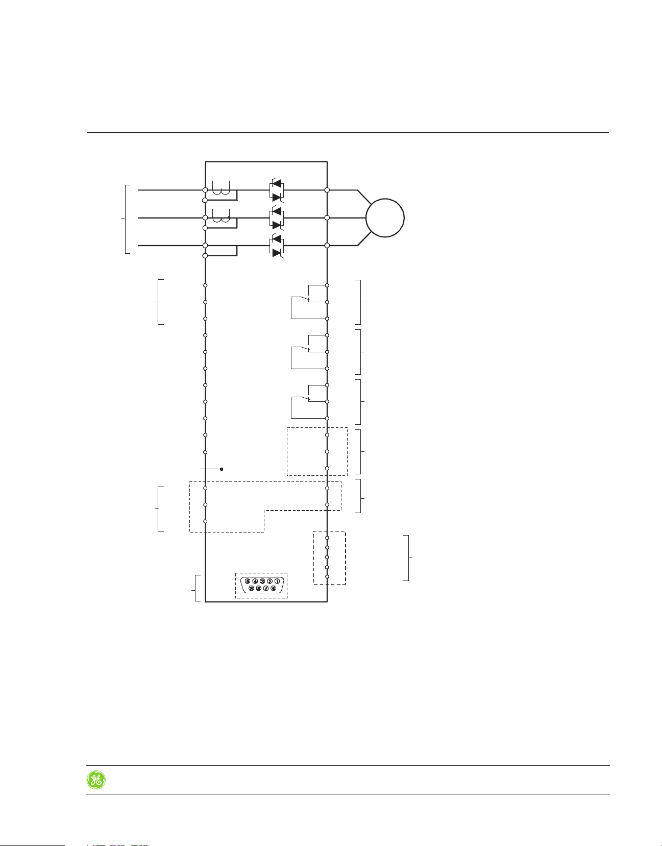
Stop
Soft Stop
Start
E.Save/Slow Speed/Reset
D. Adj./Reversing/Reset
Common
External Fault Input
Neutral
Ground
Ground
T2
T1
Grd
CT1
CT2
2T1
4T2
6T3
M
3ph
10
11
12
13
14
15
16
17
18
SG
D-
3132(-)
(+)
D+
Inmediate
RUN
Fault Relay
EOR (End Of Ramp)
Relay
RS485 Port
Analog Output
Profibus Comm
(Option)
Thermistor Input
VCL
Dr
CH
V+
Power Supply
Signal CAN-H
Drain
Signal CAN-L
Power Supply
DeviceNet (Option)
ASTAT XT Soft Starter
Technical Specifications
I/O Wiring, Basic scheme
Section 2Reduced Voltage Starters
Rev. 8/15
Prices and data subject to
change without notice
Control Catalog
2-9
Solid State
A1
L1
Q1
12345
6
F1
1L12T1
M
3
~
U1 V1 W1
L2
3L24T2L35L36T3
Q2
132
4
GND
T1
Q3
12
L
N
STOP 4
0 STOP
I START
SOFT STOP 5
START 6
18
EOR
R
17 16 15
FAULT
R
14 13 12
RUN
R
11 10
A1
L1
Q1
12345
6
F1
1L12T1
M
3
~
U1 V1 W1
L2
3L24T2L35L36T3
Q2
132
4
GND
T1
Q3
12
L
N
STOP 4
SOFT STOP 5
0 STOP
I START
START 6
18
EOR
R
17 16 15
FAULT
R
14 13 12
RUN
R
11 10
A1
L1
Q1
12345
6
F1
1L12T1
M
3
~
U1 V1 W1
L2
3L24T2L35L36T3
Q2
132
4
GND
T1
Q3
12
L
N
STOP 4
STOP
SOFT STOP 5
START
START 6
18
EOR
R
17 16 15
FAULT
R
14 13 12
RUN
R
11 10
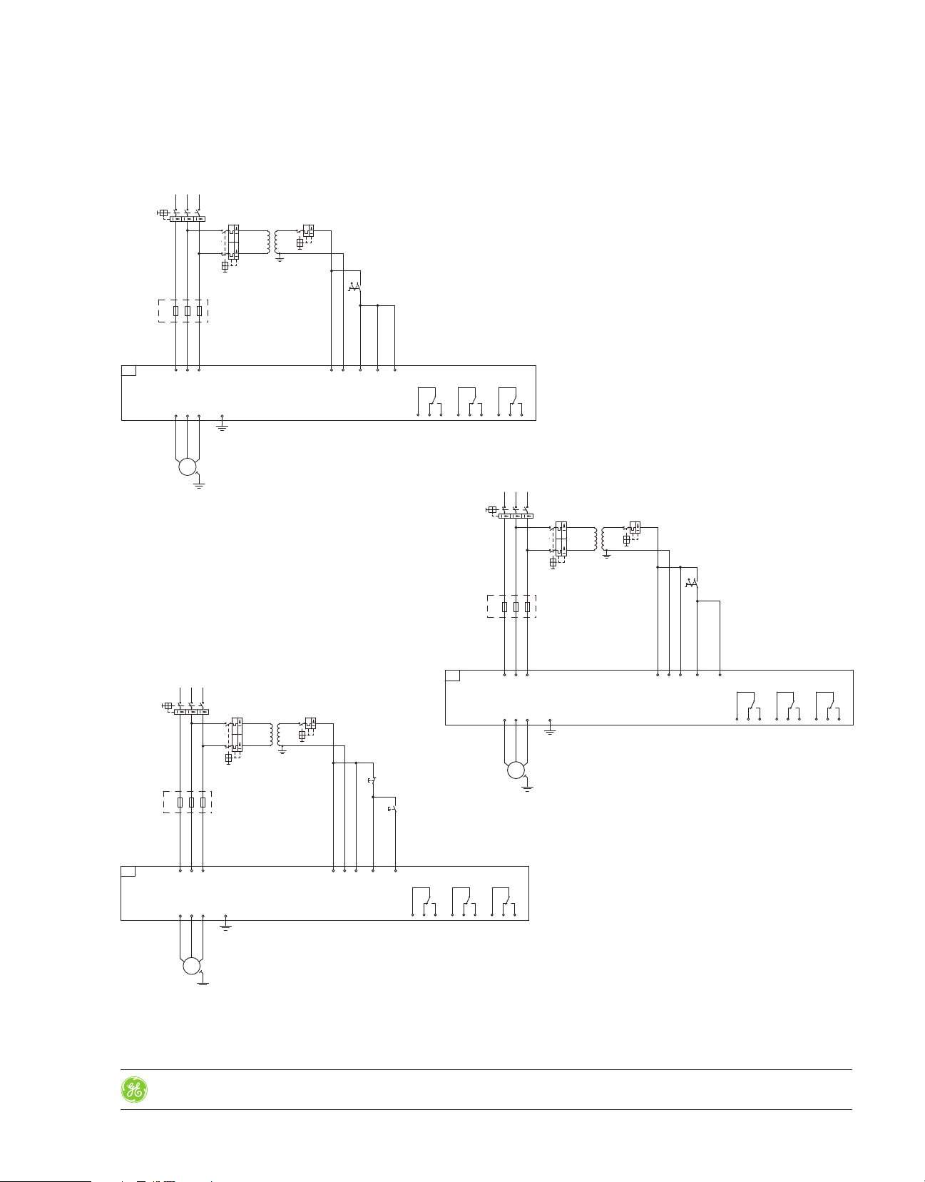
ASTAT XT Soft Starter
Application Wiring Diagrams - Basic Diagram without Line Contactor
Section 2Reduced Voltage Starters
With Soft Start and Coast to St op by
Permanent Command Contro l
With Soft Start and Soft S top by
Permanent Command Contro l
Rev. 8/15
Prices and data subject to
change without notice
With Soft Start and Soft S top by
Push B ut ton Control
Notes:
- Check coordination tables for proper selection of Breaker and Line contactor.
- Control Voltage and Control Input voltage are from same source in above example. Please check
manuals if you have different sources for Control Voltage and Control input Voltage.
- Semiconductor Fuses “F” are only required for Type 2 coordination. Please check coordination
tables
- ASTAT XT Soft Starter can operate without line contactor, however the use of a line contactor
will increase the operation safety, and provide a way to switch off the Breaker in case of an
emergency.
Control Catalog
2-11

Reduced Voltage Starters
A1
L1
Q1
12345
6
KM1
1
2
.8
F1
1L12T1
M
3
~
U1 V1 W1
L2
3
4
3L24T2
L3
5
6
5L36T3
Q2
132
4
GND
T1
Q3
12
L
N
K1
21
24
STOP 4
SOFT STOP 5
START 6
A1
FAULT
RELAY
18
Q1
13
14
.3
STOP
START
13
15
K1
A1
A2
EOR
R
17 16
K1
11
14
A1
15
RUN
RELAY
FAULT
R
14
KM1
13
14
10
12
KM1
A1
A2
13 12
K1
31
34
RUN
R
11 10
A1
L1
Q1
12345
6
KM1
1
2
.8
F1
1L12T1
M
3
~
U1 V1 W1
L2
3
4
3L24T2
L3
5
6
5L36T3
Q2
132
4
GND
T1
Q3
12
L
N
STOP 4
K1
21
24
SOFT STOP 5
START 6
A1
FAULT
RELAY
18
Q1
13
14
.3
STOP
START
13
15
K1
A1
A2
EOR
R
17 16
K1
11
14
A1
15
RUN
RELAY
FAULT
R
14
KM1
13
14
10
12
KM1
A1
A2
13 12
K1
31
34
RUN
R
11 10
Solid State
ASTAT XT Soft Starter
Application Wiring Diagrams - Basic Diagram with Line Contactor
Section 2
With Soft Start and Coast to St op by Push Button Control
With Soft Start and Soft S top by Pu sh Button Control
2-12
Control Catalog
Notes:
- Check coordination tables for proper selection of Breaker and Line contactor.
- Control Voltage and Control Input Voltage are from same source in above example. Please check
manuals if you have different sources for Control Voltage and Control Input Voltage.
- Semiconductor Fuses “F” are only required for Type 2 coordination. Please check coordination
tables
Rev. 8/15
Prices and data subject to
change without notice

Solid State
BPC
KM2
1
2
345
6
A1
A B C
L1
Q1
12345
6
KM1
1
2
F1
1L12T1
M
3
~
U1 V1 W1
L2
3
4
3L24T2
L3
5
6
5L36T3
Q2
132
4
GND
T1
Q3
12
L
N
STOP 4
K1
21
24
SOFT STOP 5
START 6
A1
FAULT
RELAY
18
Q1
13
14
STOP
START
13
15
K1
A1
A2
EOR
R
17 16
K1
11
14
A1
15
RUN
RELAY
FAULT
R
14
KM1
13
14
10
12
KM1
A1
A2
13 12
K1
31
34
RUN
R
11 10
A1
EOA
RELAY
16
18
KM2
A1
A2
KM3
1
2
345
6
BPC
KM2
1
2
345
6
A1
A B C
L1
Q1
12345
6
KM1
1
2
F1
1L12T1
U1U2V1V2W1
PE
W2
L2
3
4
3L24T2
L3
5
6
5L36T3
Q2
132
4
GND
T1
Q3
12
L
N
STOP 4
K1
21
24
SOFT STOP 5
START 6
A1
FAULT
RELAY
18
Q1
13
14
STOP
START
13
15
K1
A1
A2
EOR
R
17 16
K1
11
14
A1
15
RUN
RELAY
FAULT
R
14
KM1
13
14
10
12
KM1
A1
A2
13 12
K1
31
34
KM3
A1
A2
RUN
R
11 10
A1
EOA
RELAY
16
18
KM2
A1
A2
ASTAT XT Soft Starter
Application Wiring Diagrams
Section 2Reduced Voltage Starters
Basic Di ag ra m with Line a nd Bypass Contact or s
With Soft Start and Soft S top by Pu sh Button Control
With Soft Start and Soft S top by Pu sh Button Control
Rev. 8/15
Prices and data subject to
change without notice
Basic Di ag ra m in “Inside De lt a” Configuration
with L in e and Bypa ss Contactors
Notes:
- Check coordination tables for proper selection of Breaker and Line contactor.
- Control Voltage and Control Input Voltage are from same source in above example. Please check
manuals if you have different sources for Control Voltage and Control Input Voltage.
- Semiconductor Fuses “F” are only required for Type 2 coordination. Please check
coordination tables
Wrong connection of the motor, or the ASTAT XT Soft Starter when it is
Inside-delta connected may seriously damage the motor or the ASTAT
XT Soft Starter. Please check additional details given in the ASTAT XT
Soft Starter instruction manual.
Control Catalog
2-13
 Loading...