

Heavy-Duty 22.5 mm Watertight/Oiltight Push Buttons
Conformity to standards
Approvals
Finger protection at terminals
Enclosure ratings
Operating Storage
-13° to + 158°F
-25° to + 70°C
Climate Type
Temperature
Wet
Hot Wet
Variable Wet
50%
83%
92%
83% to 92%
Resistance to vibration
Resistance to shock
Operating force
Terminal Torque
12 in.-lb.
12 in.-lb.
12 in.-lb.
12 in.-lb.
12 in.-lb.
10-12 in.-lb.
10-12 in.-lb.
7-12 in.-lb.
Quick connect terminals
Electrical reliability data
Dust resistance
Thermal current
Insulation voltage
Protection from electrical shock
Insulation category
Dielectric strength
Short circuit protection
Volts (V )
Continuous (A)
Making (A)
Breaking (A)
12
10
60
10
24
10
60
10
48
10
60
10
60
10
60
10
120
10
60
6
240
10
30
3
480
10
15
1.5
600
10
12
1.2
Volts (V )
Continuous (A)
Making (A)
Breaking (A)
12
2.5
2.5
2.5
24
2.5
2.5
2.5
48
2.5
1.4
1.4
60
2.5
1.1
1.1
125
2.5
0.55
0.55
250
2.5
0.27
0.27
300
2.5
0.23
0.23
10A type gG fuse, per IEC 269.1 & 269.3
A600 (maximum make volt-amperes = 7200; maximum break volt-amperes = 720; PF = .25)
Q300 (maximum make or break volt-amperes = 69)
Group "C" per VDE 0110
2500 Volts
Suitable for use in NEMA Types 1, 3, 3R, 3S, 4, 4X, 12, and 13 enclosures. (Multi-function push buttons are suitable for NEMA Type
1 enclosures only unless used with protective rubber cap accessory.) IP66 per IEC 529, when mounted in enclosures with equal or
superior seal.
Relative HumidityTemperature
-40° to + 158°F
-40° to + 70°C
CSA C22.2 No. 14-M91 (Canada)
IEC 947.5. 1 (International)
UTE (France)
NFC 63140 (France)
JIS (Japan)
UL listed —File Number E66677
CSA Certified —File Number 16661-63
Manufacturing facility is registered to ISO 9000
Ambient temperature
Climate suitablility/humidity
Pilot duty ratings
Suitable for one female tab connector measuring 0.25 x 0.03 inches (6.35 x 0.8 mm) or two female tab connectors measuring 0.11 x 0.03
inches (2.8 x 0.8 mm).
Electrical life and reliability in low level current: 80 million operations at 12V, 5mA, resistive load. (32 contacts tested successfully for 2.5
million operations.)
In extremely dusty environments, electrical life at low level current is 250,000 operations at 12 V, 5mA, resistive load. In a clean
environment, electrical life at low level current is 10 million operations at 12 V, 5mA, resistive load.
Class I per IEC 536 for metal operators
Class II (double insulation) per IEC 536 for plastic operators
Ith = 10A per IEC 947-5-1
Ui = 660 Volts ac/dc (opposite polarity) except 2NO and 2NC blocks 300 Vac/dc
Suitable for #22-#12 AWG stranded or solid copper wires, single or parallel conductors of same size. Terminal torque: 7-12 in./lb. Parallel
conductor size combinations (stranded or solid wire):
IP2X according to IEC 529
Terminal identification per CENELEC EN 50013
UL508 (USA)
NEMA ICS-2 (USA)
VDE 0660 (Germany)
BSI (Great Britain)
CEI EN60947.5. 1 (Italy)
CENELEC EN 5000 7 (Europe)
74°F (23°C)
74°F (23°C)
104°F (40°C
)
74° to 104°F (23° to 40°C)
Wire capacity and terminal
torque requirements
(for all power supplies and contact
blocks)
Per IEC 68-2-6. 16g with a frequency from 40-500 Hz and maximum peak-to-peak amplitude of 0.75mm.
According to MIL 202B, method 202A. Test was performed for 1/2 sinusoid for 11ms, 38g max for all operators with transformers and
100g for all other operators.
Standard push button operator: 2.5 lbs. (11N)
Each contact block: 1.3 lbs. (6N)
Selector switch operator: 2.4 in.-lb. (0.27 N-m)
#12 with #14
#14 with #16
#16 with #18
#16 with #20
#16 with #22
#18 with #22
#18 with #20
#20 with #22
Parallel Conductor Size Combinations (Stranded or Solid Wire)
C-2000
Technical Data
600 VAC Max., 300 VDC Max.
10 Amps Continuous AC, 2.5 Amps Continuous DC
General Specifications
Section 9Pilot and Signaling Devices
Wire Terminals
Contact Data
Rev. 4/16
Prices and data subject
to change without notice
Control Catalog
9-119
Pilot and Signaling Devices
Ue (V)
Ie (A)
12
10
24
10
48
10
60
10
110
6
220
3
380
2
500
1.5
600
1.2
Ue (V)
Ie (A)
12
2.5
24
2.5
48
1.4
60
1.0
110
0.55
220
0.27
300
0.2
Acceptable panel thickness .040-.236 inches (1-6mm)
NC: slow make, double break (positive opening)
NO: slow make, double break
Self-cleaning (wiping action) contact
Double-bridge contacts with four points of contact
AC15 Control of AC Electromagnetic Loads
DC13 Control of DC Electromagnets
Contact characteristics
IEC utilization categories
Rated operational voltage and current
Rated operational voltage and current
Logic reed contact data
Force required to forcibly remove
contact blocks and flange
NC: Single break
NO: Single break
120 Vac maximum, 0.15A maximum, 8VA maximum
30 Vdc maximum, .15A maximum, 4.5W maximum
Contact block or power supply from flange: 27 lbs. (118 N)
3- or 5-block flange from metal operator: 88 lbs. (392 N)
3- or 5-block flange from plastic operator: 66 lbs. (294 N)
Operator locking ring torque 26 in./lb. (3 N-m)
Contact fidelity
Contact resistance ≤25mOhm per IEC 255.7 category 3 @ 24V, 1 amp
Minimum current: 5mA
Minimum voltage: 12 Vac/dc, maximum resistance—2 ohms
Operators Number of Operations
Standard push buttons 3,000,000
Illuminated push buttons
1,000,000—3,000,000
1
Momentary mushroom-head push buttons 3,000,000
Maintained mushroom-head push buttons 500,000
Push-to-latch, turn-to-release mushroom-head push buttons 300,000
3-position mushroom-head push buttons 300,000
Nonilluminated selector switches 1,000,000
Illuminated selector switches 500,000
Joysticks 500,000
Toggle switches 500,000
Wobble sticks 1,000,000
Key-operated push buttons 500,000
Selector push buttons 1,000,000
1
Number of operations dependent on the operating duration of the lamp. If the lamp is left on for long periods of time,
its heat can reduce mechanical life. All illuminated push buttons meet at least 1,000,000 operations.
Heavy-Duty 22.5 mm Watertight/Oiltight Push Buttons
C-2000
Technical Data
600 VAC Max., 300 VDC Max.
10 Amps Continuous AC, 2.5 Amps Continuous DC
Contact Data
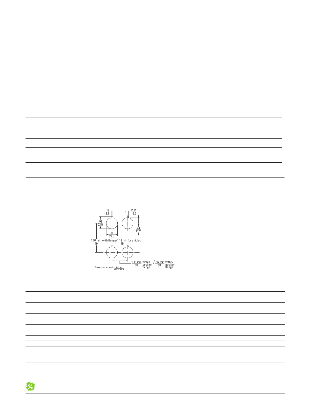
Mounting
Section 9
Mou ntin g Di mens ions
Mechanical Life Ratings for Operators
9-120
Control Catalog
Rev. 4/16
Prices and data subject
to change without notice
Pilot and Signaling Devices
Heavy-Duty 22.5 mm Watertight/Oiltight Push Buttons
C-2000
Technical Data
600 VAC Max., 300 VDC Max.
10 Amps Continuous AC, 2.5 Amps Continuous DC
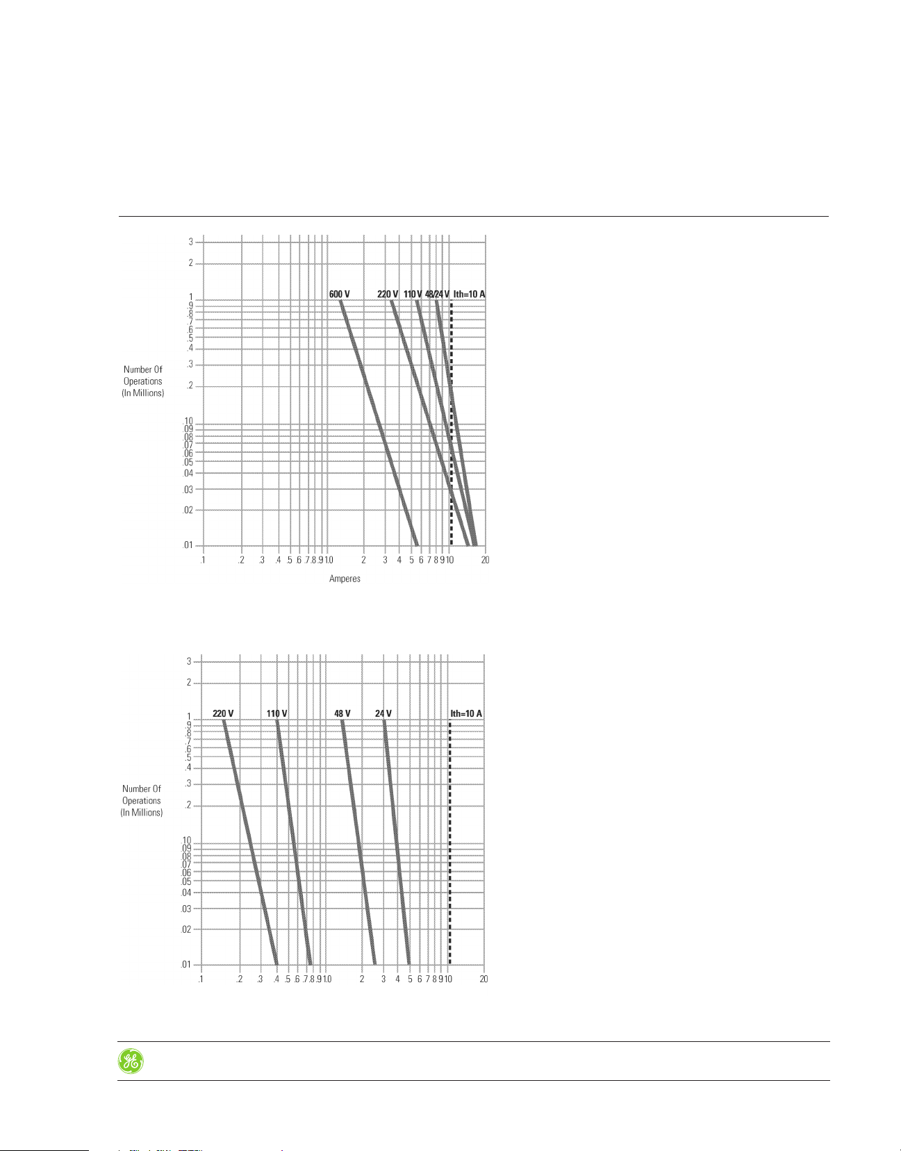
Electrical Life Ratings for Contacts
Section 9
Electrical L if e— 50 /6 0 Hz alternating curren t (inductive)
per ut il iz at io n category AC15
Electrical L if e— di rect curre nt (inductive)
per ut il iz at io n category DC13
Rev. 4/16
Prices and data subject
to change without notice
Control Catalog
9-121
 Loading...