

IEC Protective Relays
Technical Data
Section 10Logic Control
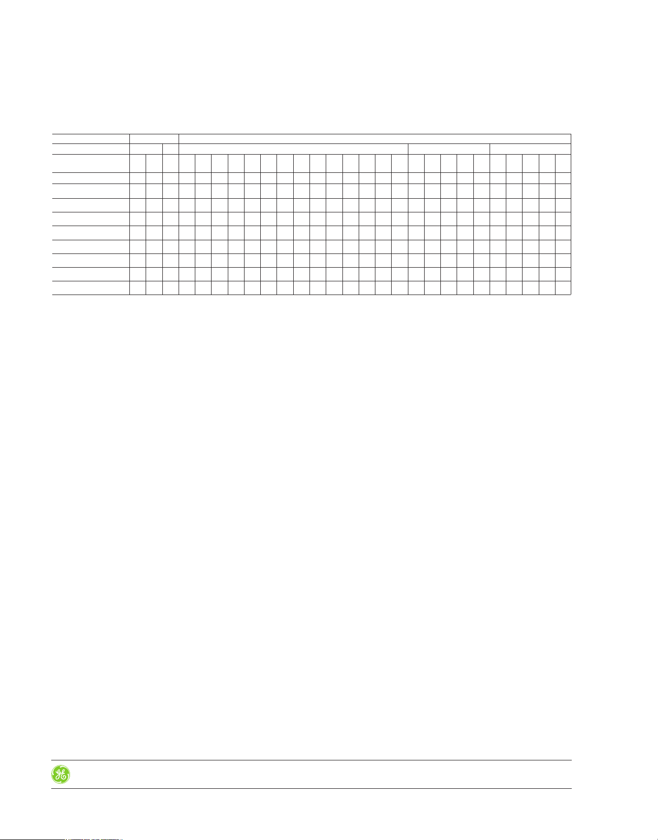
**Available Input Voltages
Direct supply Supplied with internal transformer
Current AC/DC DC AC (50/60Hz) AC (50Hz) AC (60Hz)
Voltage 240 24 24 24 48 125 110 125 220 230 230 240 400 380 400 440 500 220 240 380 440 500 220 240 380 440 500
Product Number Code None CD CD AD AG AJ AJ AK AN EN AP AR AU AU AV AX AY EN AR AU AX AY EN AR AU AX AY
RCF1
RMM 2
RPDF2-50
RPDF2-60
RS01N
RSFF1-50
RSFF1-60
RSR1
no recommended stock
•
recommended stock
••
24- 110- 220- 380-
•• •• ••••
•• •• •••••••
•••••
•• ••
•••• ••••
•••
••
•••• ••••
10-28
Control Catalog
Rev. 8/15
Prices and data subject
to change without notice
IEC Protective Relays
Technical Data
Section 10Logic Control
DINIL-02
Control Voltage
Single Voltage Dual Voltage
Terminals 2-10 220-230 VAC (Terminals 2-10)
10-30
Control Catalog
380-400 VAC (Terminals 2-11)
DINIL-02E
Rev. 8/15
Prices and data subject
to change without notice

IEC Protective Relays
Technical Data
RPDF Unbalance and Phase Failure Relays
The RPDF-electronic relay is intended for the protection of lines or electronic motors
against unbalance between phases or failure of one or more phases. Detection of
unbalance or phase failure is done by measuring phase change and not by voltage
levels. This guarantees proper operation even when there are return paths due to
motors running which are connected to the main network to be protected.
The relay is made when all conditions are normal (contact 11-14 closed); the contacts
open in the event of a failure. In this way, any failure, including that of the relay supply
voltage, will cause disconnection and prevent the supply from being left unprotected.
Setting unbalance
The unbalance of phases is a limiting factor in the life of an electric motor. The graph
below right shows the percentage temperature increase in a three-phase motor as a
function of the degree of unbalance (See standards NEMA MG 1-1433 and 34).
The percent unbalance is calculated as follows:
Section 10Logic Control
% unbalance = x 100
max. voltage deviation from average voltage
average voltage
Tripping is adjustable between 2.5 and 10%. Consequently protection is provided for
motors working closely adjusted to rated power, to others more generously sized, and
even power lines. In any case adjustments should be made so that on failure of one
phase, the relay will disconnect.
Product Number RPDF2-50 RPDF2-60
Number of Selectable NO-NC Contacts 22
Output Contacts Rated Insulation Voltage: Ui AC 400V 400V
Output Contacts Rated Insulation Voltage: Ui DC 250V 250V
Output Contacts Thermal Current Ith 6A 6A
Utilization Category AC15 Rated Voltage Ue 120/240V 120/240V
Utilization Category AC15 Rated Current Ie 2.5/1.3A 2.5/1.3A
Utilization Category DC13 Rated Voltage Ue 110/220V 110/220V
Utilization Category DC13 Rated Current Ie 0.2/0.1A 0.2/0.1A
Supply Voltage: AC (with transformer) Un 500V, 440V, 380V, 240V, 220V 500V, 440V, 240V, 220V
Line Voltage Frequency 50Hz 60Hz
Supply Voltage Tolerance +10/-20% +10/-20%
Repeat Accuracy 2% 2%
Consumption 3 VA 3 VA
Input Circuit Test Voltage 4 kV 4 kV
Unbalance Tripping (adjustable) 2.5 to 10% Un 2.5 to 10% Un
Switch ON Response Time 100 ms 100 ms
Reset Hysteresis (% of tripping value) 2% 2%
Weight 0.250, .55 lbs. 0.250, .55 lbs.
Approval & Standards VDE 0106 VDE 0106
For ambient conditions data see page 10-37, Table 2.
1
For supply voltage less than 300V.
EN 50001 EN 50001
EN 50005 EN 50005
EN 50011 EN 50011
DIN 46199 DIN 46199
IEC 947.5.1 IEC 947.5.1
UNE 20-119 UNE 20-119
UL508
1
UL508
1
RPDF
10-32
Control Catalog
Rev. 8/15
Prices and data subject
to change without notice

Logic Control
IEC Protective Relays
Technical Data
RSFF Phase Sequence and Phase Failure Relays
The RSFF relay is designed to detect phase sequence errors and/or phase failures in
three phase lines by measuring the three phase voltage angle and amplitude. An external potentiometer is used to adjust the level of acceptable unbalance (2.5% to 10.0%).
Product Number RSFF1-50 RSFF1-60
Number of Selectable NO-NC Contacts 11
Output Contacts Rated Insulation Voltage: Ui AC 400V 400V
Output Contacts Rated Insulation Voltage: Ui DC 250V 250V
Output Contacts Thermal Current Ith 6A 6A
Utilization Category AC15 Rated Voltage Ue 120/240V 120/240V
Utilization Category AC15 Rated Current Ie 2.5/1.3A 2.5/1.3A
Utilization Category DC13 Rated Voltage Ue 110/220V 110/220V
Utilization Category DC13 Rated Current Ie 0.2/0.1A 0.2/0.1A
Supply Voltage: AC (with transformer) Un 440V, 380-400V, 220-230V 380-400V, 220-230V
Line Voltage Frequency 50Hz 60Hz
Supply Voltage Tolerance +15/-20% +15/-20%
Repeat Accuracy 2% 2%
Consumption 3 VA 3 VA
Input Circuit Test Voltage 4 kV 4 kV
Switch ON Response Time 200 ms 200 ms
Switch OFF Response Time 1s 1s
Weight 0.230, .50 lbs. 0.230, .50 lbs.
Approval & Standards VDE 0106, EN 50001, VDE 0106, EN 50001,
For ambient conditions data see page 10-37, Table 2.
Note: The relay has one LED that lights when the output contact is made.
1
For supply voltage less than 300V.
EN 50005, EN 50011, EN 50005, EN 50011,
DIN 46199, IEC 947.5.1, DIN 46199, IEC 947.5.1,
UNE 20-119, UL508
1
UNE 20-119, UL508
1
Section 10
RSFF
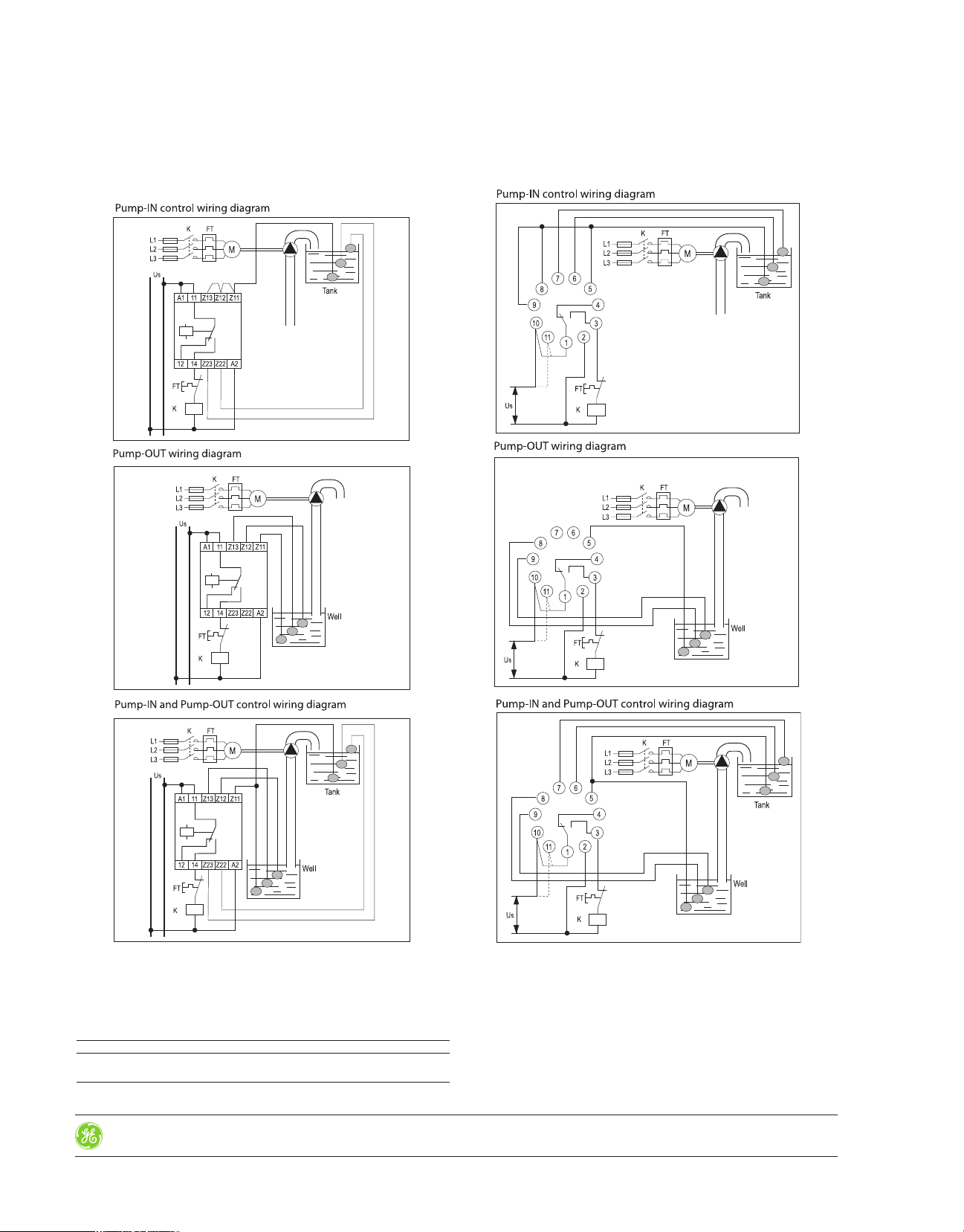
RMM 2 Maximum and Minimum Voltage Protection (Three Phase) Relays
These voltage-sensitive relays with two selectable output contacts remain closed (contact between 11-14 or between 21-24) when voltage is within tolerance limits, and open
when voltage surpasses these limits. The relays can be used to detect low or over voltage in balanced single or three-phase systems, and maximum and minimum tripping
values are adjustable by means of two potentiometers.
Product Number RMM 2
Number of Selectable NO-NC Contacts 2
Output Contacts Rated Insulation Voltage: Ui AC 400V
Output Contacts Rated Insulation Voltage: Ui DC 250V
Output Contacts Thermal Current Ith 6A
Utilization Category AC15 Rated Voltage Ue 120/240V
Utilization Category AC15 Rated Current Ie 2.5/1.3A
Utilization Category DC13 Rated Voltage Ue 110/220V
Utilization Category DC13 Rated Current Ie 0.2/0.1A
Supply Voltage: AC (with transformer) Un 500V, 440V, 400V, 380V,
Supply Voltage Un: DC/AC (direct) 24V
Line Voltage Frequency 50/60 Hz
Supply Voltage Tolerance +15/-20%
Repeat Accuracy 2%
Consumption 3 VA
Input Circuit Test Voltage 4 kV
Low Voltage Tripping (adjustable) -5 to +20%
Overvoltage Tripping (adjustable) +5 to +15%
Switch ON Response Time 100 ms
Reset Hysteresis (% of tripping value) 5% approx.
Weight 0.250, .55 lbs.
Approval & Standards VDE 0106, EN 50001, EN 50005,
For ambient conditions data see page 10-37, Table 2.
Note: The relay has one LED that lights when the output contact is made.
1
For supply voltage less than 300V.
240V, 220V, 125V, 110V, 24V
EN 50011, DIN 46199, IEC 947.5.1,
UNE 20119, UL508
1
RMM 2
Rev. 8/15
Prices and data subject
to change without notice
Control Catalog
10-33

IEC Protective Relays
Technical Data
RS01N Thermistor Relays
This thermal probe relay is sensitive to the resistance of several thermal probes (thermistors,
RTD) connected to P1 and P2 and defects overheating in motor windings, transformers, etc.
The relay disconnects when probe resistance exceeds 2500 ohms and cannot reset until
resistance is lower than 1500 ohms. The absence of control voltage to the A1 and A2
terminals causes the relay to trip. When the relay trips due to motor overheating it can
be reset either manually, automatically or remotely.
The RS01N detects those cases of shortcircuited probe cables (resistance lower than 20
ohms) or cut probe cables (resistance higher than 2.5 k ohms). The resistance at 77°C of
the probe circuit must be within a range of 40 to 600 ohms.
Product Number RS01N
Number of Selectable NO-NC Contacts 1
Output Contacts Rated Insulation Voltage: Ui AC 400V
Output Contacts Rated Insulation Voltage: Ui DC 250V
Output Contacts Thermal Current Ith 6A
Utilization Category AC15 Rated Voltage Ue 120/240V
Utilization Category AC15 Rated Current Ie 2.5/1.3A
Utilization Category DC13 Rated Voltage Ue 110/220V
Utilization Category DC13 Rated Current Ie 0.2/0.1A
Supply Voltage: AC (with transformer) Un 380-400, 240 220-230, 125 110, 48
Line Voltage Frequency 50/60 Hz
Supply Voltage Tolerance +10/-15%
Repeat Accuracy 2%
Consumption 3VA
Input Circuit Test Voltage 4 kV
Switch OFF Response Time 100 ms
Hysteresis 1 k ohms
Probe Resistance min. (at 25°C) 40 Ohms
Probe Resistance max. (at 25°C) 600 Ohms
Max. Voltage in Terminals P1-P2 for R=2.5kV < 1.6 V
Repeat Accuracy with 0.85 - 1.1 Un 2%
Weight 0.250, .55 lbs.
Approval & Standards VDE 0106, EN 50001, EN 50005, UL508, EN 50011, DIN 46199,
For ambient conditions data see page 10-37, Table 2.
Note: The relay has one LED that lights when the output contact is made.
DIN VDE 0660-303, UNE 20119, IEC 947.5.1, IEC 34-11-2
Section 10Logic Control
RS01N
RSR1 Adjustable Thermistor Relays
This relay has been designed for temperature control by type PT100 temperature probes.
The relay is normally ON (contacts 11-14 closed). The relay turns OFF (1) when the
detected temperature exceeds the threshold value, (2) if the probe wires are cut or (3) if
the control voltage is interrupted.
Product Number RSR1…
Number of Selectable NO-NC Contacts 1
Output Contacts Rated Insulation Voltage: Ui AC 400V
Output Contacts Rated Insulation Voltage: Ui DC 250V
Output Contacts Thermal Current Ith 6A
Utilization Category AC15 Rated Voltage Ue 120/240V
Utilization Category AC15 Rated Current Ie 2.5/1.3A
Utilization Category DC13 Rated Voltage Ue 110/220V
Utilization Category DC13 Rated Current Ie 0.2/0.1A
Supply Voltage: AC (with transformer) Un 380-400V, 240V, 220-230V, 125V, 110V, 48V
Line Voltage Frequency 50/60 Hz
Supply Voltage Tolerance +10/-15%
Repeat Accuracy 2%
Consumption 3VA
Input Circuit Test Voltage 4 kV
Switch OFF Response Time 100 ms
Hysteresis 10%
Weight 0.260, 0.57 lbs.
Approval & Standards VDE 0106, EN 50001, EN 50005, UL508
For ambient conditions data see page 10-37, Table 2.
Note: The relay has one LED that lights when the output contact is made.
1
For supply voltage less than 300V.
DIN 46199, UNE 20119, IEC 947.5.1
1
, EN 50011,
RSR1
10-34
Control Catalog
Rev. 8/15
Prices and data subject
to change without notice

Logic Control
IEC Protective Relays
Technical Data
RCF-1 Frequency Control Relays
The frequency control relay is sensitive to the frequency of the signal applied to terminals
B1 and B2. The output contacts close when the frequency falls below the selected
threshold (adjustable by potentiometer).
There are three frequency setting ranges: 5-15 Hz, 15-45 Hz, 45-135 Hz. Switching is
independent of the input signal’s amplitude being monitored at B1-B2. The signal’s wave
form can be sinusoidal, square, triangular, etc. This relay is suitable for suppression of
rotor resistance in slip-ring asynchronous motor starters, speed reversal detector in
wound rotor motors and frequency control in generating sets.
Product Number RCF-1…
Number of Selectable NO-NC Contacts 1
Output Contacts Rated Insulation Voltage: Ui AC 400V
Output Contacts Rated Insulation Voltage: Ui DC 250V
Output Contacts Thermal Current Ith 6A
Utilization Category AC15 Rated Voltage Ue 120/240V
Utilization Category AC15 Rated Current Ie 2.5/1.3A
Utilization Category DC13 Rated Voltage Ue 110/220V
Utilization Category DC13 Rated Current Ie 0.2/0.1A
Supply Voltage: AC (with transformer) Un 380-400V, 240V, 220-230V, 125V, 110V, 48V, 24V
Line Voltage Frequency 50/60 Hz
Supply Voltage Tolerance +10/-15%
Voltage between B1-B2 terminals 15V to 500V
Repeat Accuracy 2%
Consumption 3VA
Input Circuit Test Voltage 4 kV
Switch ON Response Time 100 ms
Switch OFF Response Time 800 ms
Hysteresis 1.5 Hz approx.
Repeat Accuracy with 0.85 - 1.1 Un 2%
Weight 0.280, .61 lbs.
Approval & Standards VDE 0106, EN 50001, EN 50005, UL508
For ambient conditions data see page 10-37, Table 2.
Note: The relay has one LED that lights when the output contact is closed.
1
For supply voltage less than 300V.
DIN 46199, UNE 20119, IEC 947.5.1
1
, EN 50011,
Section 10
RCF-1
Rev. 8/15
Prices and data subject
to change without notice
Control Catalog
10-35
 Loading...