

Page 1
Dry Type Transformers
Buck-Boost
Encapsulated
For Bucking and Boosting Voltage
Product Description
Buck boost transformers are small, single-phase, dry type distribution transformers designed and shipped as insulating/isolating
transformers. They have a dual voltage primary and a dual voltage secondary. These transformers can be connected for a wide
range of voltage combinations. The most common use is to buck
(lower) or boost (raise) the supply voltage a small amount, usually 5 to 27%. Buck boost transformers comply with NEC Article
210-9, Exception 1, when field connected as an autotransformer.
GE bucking and boosting transformers provide an economical
and convenient means for bucking or boosting voltage, usually
no more than ±20% on single- and three-phase circuits. They are
compact, relatively light in weight, and can be easily installed for
indoor or outdoor service.
Buck-boost transformers are employed primarily for boosting
single-and three-phase circuits by connecting them as autotransformers. When connected as an autotransformer, only the
low-voltage, high-current capacity secondary windings are
required to carry the load. Because this load is only transformed
over a small change in voltage, the buck-boost transformer can
handle loads many times its nameplate kVA rating.
The transformers with series-multiple 12/24, 24/48, or 16/32 Volt
secondary windings are suitable for a wide variety of applications. Two or more units can be used in various combinations to
obtain many other special voltages. (For fluctuating voltage conditions, refer to Power Conditioning Equipment Products section
starting on page 10-36).
Advantages
—Efficient insulating materials permit compact size and
light weight
—Dual voltage primary and dual voltage secondary for
maximum versatility
—Large, front-accessible wiring compartment permits fast,
easy wiring
—Convenient conduit knockouts located on side, bottom and
back of wiring compartment
—GE Buck-Boost Transformer Selector makes selection fast
and easy
—Many GE buck-boost transformers fit competitor mounting
footprints
—Indoor or outdoor service
Key Features
—Convenient and least expensive method of matching line
voltage with equipment voltage
—More efficient than equivalent isolation transformers
—Ability to handle loads up to 20 times nameplate rating when
connected as an autotransformer
—Ideal for changing line voltages by small amounts
—Primary voltages include 120V, 240V and 480V
—Secondary voltages include 12V, 16V, 24V, 32V, 48V
—UL and cUL Listed
Section 10
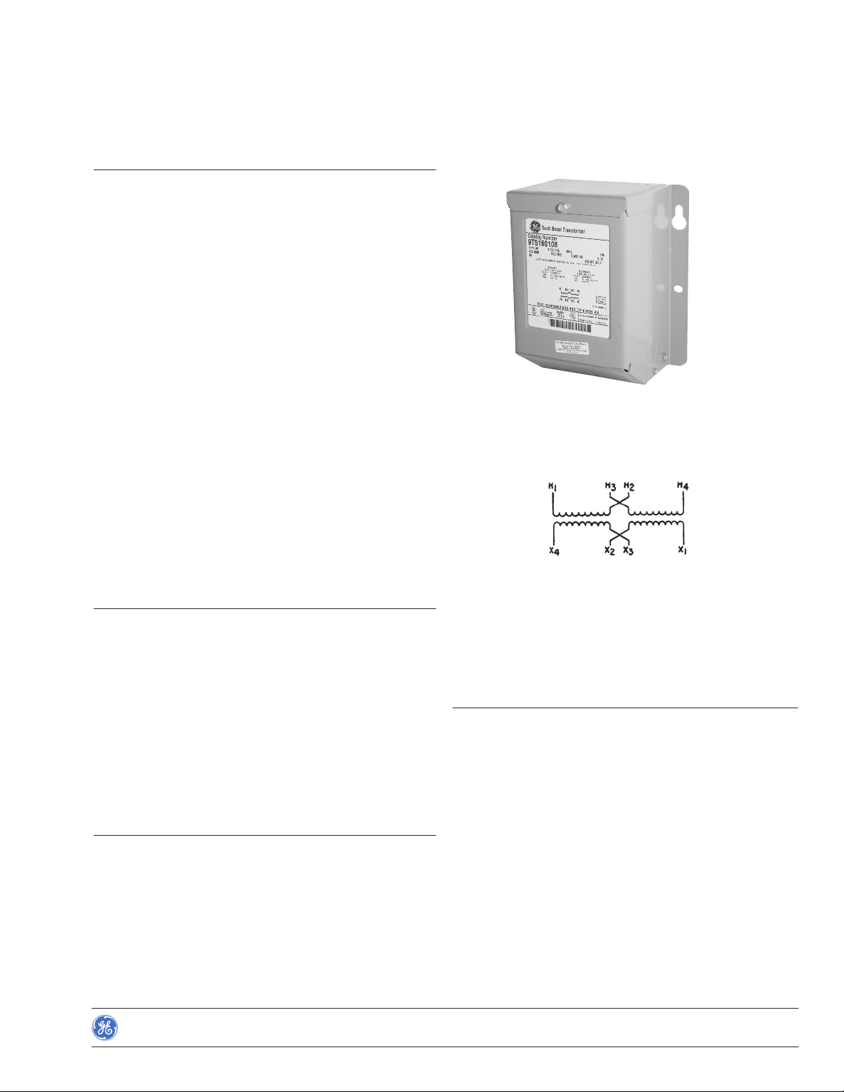
Indoor/Outdoor Typ e QB Transformer; Single-Phase
Wiring Diagram for Lo w Volt ag e Loads
—Qualified to the seismic requirements of IEEE-693-1997 and
IBC-2003
—ABS (American Bureau of Shipping) Type Approved
Applications
—International voltage adaptation
—Commercial and industrial air conditioning
—Heating systems
—Induction motors
—Voltage line drop correction
—Landscape lighting
—Low-voltage lighting
—Marine and Offshore - ABS Classed Vessels
Efficient operation of electrical equipment requires that line voltage be at or near the nameplate rating of the equipment. In
order to match available line voltage (whether it be too high or
low) with equipment voltage, buck-boost transformers provide
the most
Do not use buck-boost transformers to solve a fluctuating voltage
problem. They should be used to compensate for high- or lowvoltage conditions only when the available line voltage is
reasonably constant.
convenient and least expensive method.
Rev. 11/13
Data subject to change
without notice
BuyLog™Catalog
10-51
Page 2

Dry Type Transformers
Section 10
Buck-Boost
Encapsulated
For Bucking and Boosting Voltage
Single-Phase Indoor/Outdoor Type QB 60 Hz UL Listed C-UL Listed
Input Voltage Output Voltage kVA Height (in) Width (in) Depth (in) Weight (Lbs.) Size Number
120/240 Volts 12/24 Volts 0.05 6.38 5.12 3.25 6 6100 9T51B0102
120/240 Volts 12/24 Volts 0.075 6.38 5.12 3.25 6 6200 9T51B0103
120/240 Volts 12/24 Volts 0.1 6.38 5.12 3.25 6 6200 9T51B0104
120/240 Volts 12/24 Volts 0.15 7.38 6.12 4.25 10 8175 9T51B0105
120/240 Volts 12/24 Volts 0.25 7.38 6.12 4.25 10 8175 9T51B0107
120/240 Volts 12/24 Volts 0.5 8.38 6.88 4.88 20 10225 9T51B0108
120/240 Volts 12/24 Volts 0.75 9.62 7.88 5.50 25 12200 9T51B0109
120/240 Volts 12/24 Volts 1 9.62 7.88 5.50 25 12225 9T51B0110
120/240 Volts 12/24 Volts 1.5 11.12 9.38 6.72 40 14200 9T51B0111
120/240 Volts 12/24 Volts 2 11.12 9.38 6.72 50 14300 9T51B0112
120/240 Volts 12/24 Volts 3 9.38 6.72 55 14350 9T51B0113
120/240 Volts 16/32 Volts 0.05 6.38 5.12 3.25 6 6100 9T51B0122
120/240 Volts 16/32 Volts 0.075 6.38 5.12 3.25 6 6200 9T51B0123
120/240 Volts 16/32 Volts 0.1 6.38 5.12 3.25 6 6200 9T51B0124
120/240 Volts 16/32 Volts 0.15 7.38 6.12 4.25 10 8175 9T51B0125
120/240 Volts 16/32 Volts 0.25 7.38 6.12 4.25 10 8175 9T51B0127
120/240 Volts 16/32 Volts 0.5 8.38 6.88 4.88 20 10225 9T51B0128
120/240 Volts 16/32 Volts 0.75 9.62 7.88 5.50 25 12200 9T51B0129
120/240 Volts 16/32 Volts 1 9.62 7.88 5.50 30 12300 9T51B0130
120/240 Volts 16/32 Volts 1.5 11.12 9.38 6.72 40 14200 9T51B0131
120/240 Volts 16/32 Volts 2 11.12 9.38 6.72 50 14300 9T51B0132
120/240 Volts 16/32 Volts 3 9.38 6.72 55 14350 9T51B0133
240/480 Volts 24/48 Volts 0.05 6.38 5.12 3.25 6 6100 9T51B0202
240/480 Volts 24/48 Volts 0.075 6.38 5.12 3.25 6 6200 9T51B0203
240/480 Volts 24/48 Volts 0.1 6.38 5.12 3.25 6 6200 9T51B0204
240/480 Volts 24/48 Volts 0.15 7.38 6.12 4.25 10 8175 9T51B0205
240/480 Volts 24/48 Volts 0.25 7.38 6.12 4.25 10 8175 9T51B0207
240/480 Volts 24/48 Volts 0.5 8.38 6.88 4.88 20 10225 9T51B0208
240/480 Volts 24/48 Volts 0.75 9.62 7.88 5.50 25 12200 9T51B0209
240/480 Volts 24/48 Volts 1 9.62 7.88 5.50 30 12275 9T51B0210
240/480 Volts 24/48 Volts 1.5 11.12 9.38 6.72 40 14200 9T51B0211
240/480 Volts 24/48 Volts 2 11.12 9.38 6.72 50 14300 9T51B0212
240/480 Volts 24/48 Volts 3 11.12 9.38 6.72 55 14350 9T51B0213
Approx. Net Frame Product
Single-Phase Indoor/Outdoor Type QMS 60 Hz UL Listed C-UL Listed
Input Voltage Output Voltage kVA Height (in) Width (in) Depth (in) Weight (Lbs.) Size Number
120/240 Volts 12/24 Volts 5 14.5 10.62 11 103 16350 9T21B1037G02
120/240 Volts 16/32 Volts 5 14.5 10.62 11 115 16400 9T21B1040G02
Approx. Net Frame Product
Single-Phase Indoor/Outdoor Type QMS 50 Hz UL Listed C-UL Listed
Input Voltage Output Voltage kVA Height (in) Width (in) Depth (in) Weight (Lbs.) Size Number
120/240 Volts 12/24 Volts 5 14.5 10.62 11 115 16400 9T21B1061G02
120/240 Volts 16/32 Volts 5 14.5 10.62 11 127 16450 9T21B1064G02
NOTE: In addition to bucking or boosting low circuit voltages to related value, these transformers can be used as two winding transformers to supply the rated nameplate
low voltages, 12 to 48 Volts, two-wire or 12/24 to 24/48 Volts, three-wire. Also available in 50/60 Hz ratings.
Approx. Net Frame Product
10-52
BuyLog™Catalog
Rev. 11/13
Data subject to change
without notice
Page 3

Dry Type Transformers
Buck-Boost Selection Tables
Encapsulated
For Bucking and Boosting Voltage
5-Step Selection
The tables on these pages greatly facilitate buck-boost transformer selection. Simply follow these five easy steps:
1. Refer to the table having the same “output voltage” as the
equipment you want to operate. For example, if you are
installing a 230 Volt single-phase air conditioner, use the
230 Volt table.
2. Different available “line voltages” are listed across the top of
each table. Select the line voltage column closest to your
actual supply. If your available line voltage is exactly midway
between two listed voltage levels, you may use either voltage
column. For example, in the 230 Volt table, if you have 212
available, use either the 208 or the 216 column.
3. Read down the available line voltage column until you reach
the rated load kVA of the equipment you want to operate or
“the next higher kVA” rating. For example, in the 230 Volt table
under the 208 available line voltage column, you want to operate an air conditioner rated 2 kVA. Since 2 kVA is not list ed as
such, you must read down to the next higher value or 2.4 kVA.
Section 10
4. Once you have established this point, read across to the far
left column for the exact GE buck-boost model number for
your application. For example, the 230 Volt table under the
208 column for a 2 kVA air conditioner, read across from 2.4
(next higher kVA rating) and the model number is 9T51B0107.
5. Connect the buck-boost transformer you have selected per
the connection diagram specified at the “bottom” of the available line voltage column you used. For example, if you used
the 208 column, you would connect the buck-boost transformer per connection diagram A. That’s all there is to it! The
transformer you’ve selected will meet your exact requirements
when connected in the specified manner.
The formula for calculating single-phase kVA is:
Load Voltage × Full Load Amps
1000
The formula for calculating three-phase kVA is:
1.732 × Load Voltage × Load Amps
1000
Table 1
230 Volts Output, 60 Hertz, Single-Phase
Available Line Voltage
192 203 208 216 219 242 245 353 261 276
Product Number Load kVA
9T51B0102 ——0.480 — 0.960 1.0 — 0.530 ——
9T51B0122 — 0.360 — 0.720 ——0.770 — 0.410 —
9T51B0202 0.240 ————————0.288
9T51B0103 ——0.720 — 1.5 1.6 — 0.800 ——
9T51B0123 — 0.540 — 1.1 ——1.2 — 0.620 —
9T51B0203 0.359 ————————0.431
9T51B0104 ——0.960 — 2.0 2.1 — 1.1 ——
9T51B0124 — 0.720 — 1.5 ——1.6 — 0.820 —
9T51B0204 0.479 ————————0.575
9T51B0105 ——1.5 — 2.9 3.1 — 1.6 ——
9T51B0125 — 1.1 — 2.2 ——2.3 — 1.3 —
9T51B0205 0.719 ————————0.863
9T51B0107 ——2.4 — 4.8 5.1 — 2.7 ——
9T51B0127 — 1.8 — 3.6 ——3.9 — 2.1 —
9T51B0207 1.2 ————————1.4
9T51B0108 ——4.8 — 9.6 10.1 — 5.3 ——
9T51B0128 — 3.6 — 7.2 ——7.7 — 4.1 —
9T51B0208 2.4 ————————2.9
9T51B0109 ——7.2 — 14.4 15.2 — 7.9 ——
9T51B0129 — 5.4 — 10.8 ——11.5 — 6.2 —
9T51B0209 3.6 ————————4.3
9T51B0110 ——9.6 — 19.2 20.2 — 10.6 ——
9T51B0130 — 7.2 — 14.4 ——15.4 — 8.2 —
9T51B0210 4.8 ————————5.7
9T51B0111 ——14.4 — 28.8 30.3 — 15.9 ——
9T51B0131 — 10.8 — 21.6 ——23.0 — 12.3 —
9T51B0211 7.2 ————————8.6
9T51B0112 ——19.1 — 38.4 40.4 — 21.1 ——
9T51B0132 — 14.4 — 28.8 ——30.7 — 16.4 —
9T51B0212 9.6 ————————11.5
9T51B0113 ——28.7 — 57.5 60.5 — 31.7 ——
9T51B0133 — 21.6 — 43.2 ——46.0 — 24.5 —
9T51B0213 14.4 ————————17.3
9T21B1037G02 ——47.8 — 95.9 100.9 — 52.7 ——
9T21B1040G02 — 36.0 — 72.0 ——77.0 — 40.8 —
Connection Diagram
Page 10-60
1
The load kVA is the maximum load at voltages shown when transformers are connected as autotransformers according to the diagram referenced.
CAABBBBAAC
1
Rev. 11/13
Data subject to change
without notice
BuyLog™Catalog
10-53
Page 4

Dry Type Transformers
Section 10
Buck-Boost Selection Tables
Encapsulated
For Bucking and Boosting Voltage
Table 2
240 Volts Output, 60 Hertz, Single-Phase
200 212 218 225 229 252 256 264 272 288
Product Number Load kVA
9T51B0102 ——0.500 — 1.0 1.1 — 0.6 ——
9T51B0122 — 0.380 — 0.750 ——0.800 — 0.430 —
9T51B0202 0.250 ————————0.300
9T51B0103 ——0.750 — 1.5 1.6 — 0.825 ——
9T51B0123 — 0.570 — 1.2 ——1.2 — 0.640 —
9T51B0203 0.375 ————————0.391
9T51B0104 ——1.0 — 2.0 2.1 — 1.1 ——
9T51B0124 — 0.750 — 1.5 ——1.6 — 0.850 —
9T51B0204 0.500 ————————0.522
9T51B0105 ——1.5 — 3.0 3.2 — 1.7 ——
9T51B0125 — 1.2 — 2.3 ——2.4 — 1.3 —
9T51B0205 0.750 ————————0.782
9T51B0107 ——2.5 — 5.0 5.3 — 2.8 ——
9T51B0127 — 1.9 — 3.8 ——4.0 — 2.2 —
9T51B0207 1.3 ————————1.4
9T51B0108 ——5.0 — 10.0 10.5 — 5.5 ——
9T51B0128 — 3.8 — 7.5 ——8.0 — 4.3 —
9T51B0208 2.5 ————————2.6
9T51B0109 ——7.5 — 15.0 15.8 — 8.3 ——
9T51B0129 — 5.7 — 11.3 ——12.0 — 6.4 —
9T51B0209 3.8 ————————4.0
9T51B0110 ——10.0 — 20.0 21.0 — 11.0 ——
9T51B0130 — 7.5 — 15.0 ——16.0 — 8.5 —
9T51B0210 5.0 ————————5.2
9T51B0111 ——15.0 — 30.0 31.5 — 16.5 ——
9T51B0131 — 11.3 — 22.5 ——24.0 — 12.8 —
9T51B0211 7.5 ————————7.8
9T51B0112 ——20.0 — 40.0 42.6 — 22.0 ——
9T51B0132 — 15.0 — 30.0 ——32.0 — 17.0 —
9T51B0212 10.0 ————————10.4
9T51B0113 ——30.0 — 60.0 63.0 — 33.0 ——
9T51B0133 — 22.5 — 45.0 ——48.0 — 25.5 —
9T51B0213 15.0 ————————15.6
9T21B1037G02 ——50.0 — 100.0 105.0 — 55.0 ——
9T21B1040G02 — 37.5 — 75.0 ——80.0 — 42.5 —
Connection Diagram
Page 10-60
1
The load kVA is the maximum load at voltages shown when transformers are connected as autotransformers according to the diagram referenced.
CAABBBBAAC
Available Line Voltage
1
10-54
BuyLog™Catalog
Rev. 11/13
Data subject to change
without notice
Page 5

Dry Type Transformers
Section 10
Buck-Boost Selection Tables
Encapsulated
For Bucking and Boosting Voltage
Table 3
115 Volts Output, 60 Hertz, Single-Phase
91 96 101 105 127 130 138 146
Product Number Load kVA
9T51B0102 — 0.240 — 0.480 0.539 — 0.290 —
9T51B0122 0.180 — 0.360 ——0.410 — 0.230
9T51B0103 — 0.360 — 0.720 0.800 — 0.440 —
9T51B0123 0.270 — 0.540 ——0.610 — 0.350
9T51B0104 — 0.480 — 0.960 1.1 — 0.580 —
9T51B0124 0.360 — 0.720 ——0.820 — 0.460
9T51B0105 — 0.720 — 1.5 1.6 — 0.870 —
9T51B0125 0.540 — 1.1 ——1.3 — 0.690
9T51B0107 — 1.2 — 2.4 2.7 — 1.5 —
9T51B0127 0.900 — 1.8 ——2.1 — 1.2
9T51B0108 — 2.4 — 4.8 5.3 — 2.9 —
9T51B0128 1.8 — 3.6 ——4.1 — 2.3
9T51B0109 — 3.6 — 7.2 8.0 — 4.4 —
9T51B0129 2.7 — 5.4 ——6.1 — 3.5
9T51B0110 — 4.8 — 9.6 10.6 — 5.8 —
9T51B0130 3.6 — 7.2 ——8.2 — 4.6
9T51B0111 — 7.2 — 14.4 15.9 — 8.6 —
9T51B0131 5.4 — 10.8 ——12.2 — 6.9
9T51B0112 — 9.6 — 19.2 21.2 — 11.5 —
9T51B0132 7.2 — 14.4 ——16.3 — 9.2
9T51B0113 — 14.4 — 28.8 31.8 — 17.3 —
9T51B0133 10.8 — 21.6 ——24.4 — 13.7
9T21B1061G02 — 24.0 — 48.0 53.0 — 28.8 —
9T21B1037G02 — 24.0 — 48.0 53.0 — 28.8 —
9T21B1064G02 18.0 — 36.0 ——41.0 — 22.9
9T21B1040G02 18.0 — 36.0 ——41.0 — 22.9
Connection Diagram
Page 10-60
1
The load kVA is the maximum load at voltages shown when transformers are connected as autotransformers according to the diagram referenced.
CC D D D D C C
Available Line Voltage
1
Table 4
120 Volts Output, 60 Hertz, Single-Phase
Available Line Voltage
95 100 106 109 132 136 144 152
Product Number Load kVA
9T51B0102 — 0.250 — 0.500 0.550 — 0.300 —
9T51B0122 0.190 — 0.380 ——0.430 — 0.240
9T51B0103 — 0.380 — 0.750 0.830 — 0.450 —
9T51B0123 0.290 — 0.570 ——0.640 — 0.360
9T51B0104 — 0.500 — 1.0 1.1 — 0.600 —
9T51B0124 0.380 — 0.750 ——0.850 — 0.480
9T51B0105 — 0.750 — 1.5 1.7 — 0.900 —
9T51B0125 0.570 — 1.2 ——1.3 — 0.720
9T51B0107 — 1.3 — 2.5 2.8 — 1.5 —
9T51B0127 0.940 — 1.9 ——2.2 — 1.2
9T51B0108 — 2.5 — 5.0 5.5 — 3.0 —
9T51B0128 1.9 — 3.8 ——4.3 — 2.4
9T51B0109 — 3.8 — 7.5 8.3 — 4.5 —
9T51B0129 2.9 — 5.7 ——6.4 — 3.6
9T51B0110 — 5.0 — 10.0 11.0 — 6.0 —
9T51B0130 3.8 — 7.5 ——8.5 — 4.8
9T51B0111 — 7.5 — 15.0 16.5 — 9.0 —
9T51B0131 5.7 — 11.3 ——12.8 — 7.2
9T51B0112 — 10.0 — 20.0 22.0 — 12.0 —
9T51B0132 7.5 — 15.0 ——17.0 — 9.5
9T51B0113 — 15.0 — 30.0 33.0 — 18.0 —
9T51B0133 11.3 — 22.5 ——25.5 — 14.3
9T21B1061G02 — 25.0 — 50.0 55.0 — 30.0 —
9T21B1037G02 — 25.0 — 50.0 55.0 — 30.0 —
9T21B1064G02 18.8 — 38.0 ——43.0 — 23.8
9T21B1040G02 18.8 — 38.0 ——43.0 — 23.8
Connection Diagram
Page 10-60
1
The load kVA is the maximum load at voltages shown when transformers are connected as autotransformers according to the diagram referenced.
CC D D D D C C
1
Rev. 11/13
Data subject to change
without notice
BuyLog™Catalog
10-55
Page 6

Dry Type Transformers
Section 10
Buck-Boost Selection Tables
Encapsulated
For Bucking and Boosting Voltage
Table 5
230 Volts, 3-Wire Output , 60 Hertz, Three-Phase
Quantity Required Product
Per Bank Number Load kVA
3 9T51B0102 — 0.830 — 1.7 —
3 9T51B0122 0.620 — 1.3 ——
3 9T51B0202 ————0.480
3 9T51B0103 — 1.2 — 2.5 —
3 9T51B0123 0.930 — 1.9 ——
3 9T51B0203 ————0.720
3 9T51B0104 — 1.7 — 3.4 —
3 9T51B0124 1.2 — 2.5 ——
3 9T51B0204 ————0.960
3 9T51B0105 — 2.5 — 5.0 —
3 9T51B0125 1.9 — 3.7 ——
3 9T51B0205 ————1.44
3 9T51B0107 — 4.2 — 8.3 —
3 9T51B0127 3.1 — 6.2 ——
3 9T51B0207 ————2.4
3 9T51B0108 — 8.3 — 16.6 —
3 9T51B0128 6.2 — 12.5 ——
3 9T51B0208 ————4.8
3 9T51B0109 — 12.5 — 25.0 —
3 9T51B0129 9.3 — 18.7 ——
3 9T51B0209 ————7.2
3 9T51B0110 — 16.6 — 33.2 —
3 9T51B0130 12.5 — 25.0 ——
3 9T51B0210 ————9.6
3 9T51B0111 — 25.0 — 50.0 —
3 9T51B0131 18.7 — 37.0 ——
3 9T51B0211 ————14.4
3 9T51B0112 — 33.0 — 66.0 —
3 9T51B0132 25.0 — 50.0 ——
3 9T51B0212 ————19.2
3 9T51B0113 — 50.0 — 100.0 —
3 9T51B0133 37.5 — 75.0 ——
3 9T51B0213 ————28.8
3 9T21B1037G02 — 83.0 — 167.0 —
3 9T21B1040G02 62.0 — 125.0 ——
1
The load kVA is the maximum load at voltages shown when transformers are connected as autotransformers according to the diagram referenced.
2
See Caution page 10-58, footnote 1.
Connection Diagram
Page 10-60
181Y/105 192Y/111 203Y/117 208Y/120 277Y/160
2
Available Line Voltage
1
FFGGF
10-56
BuyLog™Catalog
Rev. 11/13
Data subject to change
without notice
Page 7

Dry Type Transformers
Section 10
Buck-Boost Selection Tables
Encapsulated
For Bucking and Boosting Voltage
Table 6
240 Volts, 3-Wire Output , 60 Hertz, Three-Phase
189Y/109 200Y/115 208Y/120
Quantity Required Product
Per Bank Number Load kVA
3 9T51B0102 — 0.870 — 1.7 —
3 9T51B0122 0.650 — 1.3 ——
3 9T51B0202 ————0.500
3 9T51B0103 — 1.3 — 2.6 —
3 9T51B0123 0.970 — 2.0 ——
3 9T51B0203 ————0.750
3 9T51B0104 — 1.7 — 3.5 —
3 9T51B0124 1.3 — 2.6 ——
3 9T51B0204 ————1.0
3 9T51B0105 — 2.6 — 5.2 —
3 9T51B0125 2.0 — 3.9 ——
3 9T51B0205 ————1.5
3 9T51B0107 — 4.3 — 8.7 —
3 9T51B0127 3.2 — 6.5 ——
3 9T51B0207 ————2.5
3 9T51B0108 — 8.7 — 17.3 —
3 9T51B0128 6.5 — 13.0 ——
3 9T51B0208 ————5.0
3 9T51B0109 — 13.0 — 26.0 —
3 9T51B0129 9.7 — 19.5 ——
3 9T51B0209 ————7.5
3 9T51B0110 — 17.3 — 34.6 —
3 9T51B0130 13.0 — 26.0 ——
3 9T51B0210 ————10.0
3 9T51B0111 — 26.0 — 52.0 —
3 9T51B0131 19.5 — 39.0 ——
3 9T51B0211 ————15.0
3 9T51B0112 — 35.0 — 70.0 —
3 9T51B0132 26.0 — 52.0 ——
3 9T51B0212 ————20.0
3 9T51B0113 — 52.0 — 104.0 —
3 9T51B0133 39.0 — 78.0 ——
3 9T51B0213 ————30.0
3 9T21B1037G02 — 87.0 — 173.0 —
3 9T21B1040G02 65.0 — 130.0 ——
1
The load kVA is the maximum load at voltages shown when transformers are connected as autotransformers according to the diagram referenced.
2
See Caution page 10-58, footnote 1.
3
When 208Y/120 Volts is the available line voltage, the 212Y/122 column may be used to obtain 236 Volts which should be satisfactory for most applications.
Connection Diagram
Page 10-60
2
Available Line Voltage
FFGGF
212Y/122
3
1
218Y/126 288Y/166
Rev. 11/13
Data subject to change
without notice
BuyLog™Catalog
10-57
Page 8

Dry Type Transformers
Section 10
Buck-Boost Selection Tables
Encapsulated
For Bucking and Boosting Voltage
Table 7
460 Volts, 3-Wire Output , 60 Hertz, Three-Phase
Quantity Required Product
Per Bank Number Load kVA
3 9T51B0102 ——1.66 — 3.32
3 9T51B0122 — 1.25 — 2.49 —
3 9T51B0202 0.830 ————
3 9T51B0103 ——2.48 — 4.96
3 9T51B0123 — 1.87 — 3.73 —
3 9T51B0203 1.2 ————
3 9T51B0104 ——3.31 — 6.62
3 9T51B0124 — 2.49 — 4.97 —
3 9T51B0204 1.7 ————
3 9T51B0105 ——4.97 — 9.94
3 9T51B0125 — 3.73 — 3.9 —
3 9T51B0205 2.5 ————
3 9T51B0107 ——8.28 — 16.6
3 9T51B0127 — 6.22 — 6.5 —
3 9T51B0207 4.2 ————
3 9T51B0108 ——16.6 — 33.2
3 9T51B0128 — 12.5 — 13.0 —
3 9T51B0208 8.3 ————
3 9T51B0109 ——24.8 — 59.6
3 9T51B0129 — 18.7 — 19.5 —
3 9T51B0209 12.5 ————
3 9T51B0110 ——33.1 — 66.2
3 9T51B0130 — 24.9 — 26.0 —
3 9T51B0210 16.6 ————
3 9T51B0111 ——49.7 — 99.4
3 9T51B0131 — 37.3 — 39.0 —
3 9T51B0211 24.9 ————
3 9T51B0112 ——66.3 — 133.0
3 9T51B0132 — 49.7 — 52.0 —
3 9T51B0212 33.2 ————
3 9T51B0113 ——99.3 — 198.6
3 9T51B0133 — 74.6 — 78.0 —
3 9T51B0213 49.8 ————
3 9T21B1037G02 ——166.0 — 322.0
3 9T21B1040G02 — 125.0 — 130.0 —
1
Caution: If input is 3-wire Delta or 4-wire midtapped Delta, the neutral established from the bank of buck-boost transformers must be insulated and isolated
from the input power neutral and/or ground.
2
The load kVA is the maximum load at voltages shown when transformers are connected as autotransformers according to the diagram referenced.
Connection Diagram
Page 10-60
1
Available Line Voltage — 3- or 4-Wire
385 406 418 432 438
2
FHHII
10-58
BuyLog™Catalog
Rev. 11/13
Data subject to change
without notice
Page 9

Dry Type Transformers
Section 10
Buck-Boost Selection Tables
Encapsulated
For Bucking and Boosting Voltage
Table 8
480 Volts, 3-Wire Output , 60 Hertz, Three-Phase
Quantity Required Product
Per Bank Number Load kVA
3 9T51B0122 — 1.3 — 2.6
3 9T51B0202 0.866 ———
3 9T51B0103 ——2.6 —
3 9T51B0123 — 1.95 — 3.9
3 9T51B0203 1.3 ———
3 9T51B0104 ——3.5 —
3 9T51B0124 — 2.6 — 5.2
3 9T51B0204 1.7 ———
3 9T51B0105 ——5.2 —
3 9T51B0125 — 3.9 — 7.8
3 9T51B0205 2.6 ———
3 9T51B0107 ——8.7 —
3 9T51B0127 — 6.3 — 13.0
3 9T51B0207 4.3 ———
3 9T51B0108 ——17.4 —
3 9T51B0128 — 13.0 — 26.0
3 9T51B0208 8.7 ———
3 9T51B0109 ——26.0 —
3 9T51B0129 — 19.5 — 39.0
3 9T51B0209 13.0 ———
3 9T51B0110 ——35.0 —
3 9T51B0130 — 26.0 — 52.0
3 9T51B0210 17.3 ———
3 9T51B0111 ——52.2 —
3 9T51B0131 — 39.0 — 78.0
3 9T51B0211 26.0 ———
3 9T51B0112 ——69.0 —
3 9T51B0132 — 52.0 — 104.0
3 9T51B0212 34.6 ———
3 9T51B0113 ——104.0 —
3 9T51B0133 — 78.0 — 156.0
3 9T51B0213 51.9 ———
3 9T21B1037G02 ——174.0 —
3 9T21B1040G02 — 130.0 — 260.0
9T51B0102 ——1.74 —
Connection Diagram
Page 10-60
1
Available Line Voltage — 3- or 4-Wire
400 424 436 450
2
FHHI
Table 9
208 Volts, 3-Wire, 60 Hertz, Three-Phase
Quantity Required Product
Per Bank Number Load kVA
2 9T51B0102 1.6 — 0.800 —
2 9T51B0122 — 1.2 — 0.640
2 9T51B0103 2.3 — 1.2 —
2 9T51B0123 — 1.8 — 0.960
2 9T51B0104 3.2 — 1.6 —
2 9T51B0124 — 2.4 — 1.3
2 9T51B0105 4.7 — 2.5 —
2 9T51B0125 — 3.6 — 1.9
2 9T51B0107 7.8 — 4.1 —
2 9T51B0127 — 6.0 — 3.2
2 9T51B0108 16 — 8.0 —
2 9T51B0128 — 12.0 — 6.4
2 9T51B0109 23.6 — 12.4 —
2 9T51B0129 — 18.0 — 9.6
2 9T51B0110 31.5 — 16.5 —
2 9T51B0130 — 24.0 — 12.7
2 9T51B0111 47.5 — 24.8 —
2 9T51B0131 — 36.0 — 19.1
2 9T51B0112 63.0 — 33.0 —
2 9T51B0132 — 48.0 — 25.6
2 9T51B0113 94 — 49.6 —
2 9T51B0133 — 72.0 — 38.3
1
Caution: If input is 3-wire Delta or 4-wire midtapped Delta, the neutral established from the bank of buck-boost transformers must be insulated and isolated
from the input power neutral and/or ground.
2
The load kVA is the maximum load at voltages shown when transformers are connected as autotransformers according to the diagram referenced.
Connection Diagram
Page 10-60
1
Available Line Voltage — 3- or 4-Wire
218 222 229 236
2
JJZZ
Rev. 11/13
Data subject to change
without notice
BuyLog™Catalog
10-59
Page 10

Dry Type Transformers
Buck-Boost Connection Diagrams
Encapsulated
For Bucking and Boosting Voltage
Connection Diagrams
Section 10
10-60
BuyLog™Catalog
Rev. 11/13
Data subject to change
without notice
 Loading...