

Page 1

Order codes
B.2 Series M - Auxiliary contactors
B.6 Series RL - Auxiliary contactors
Series M - Auxiliary contactors
B.9 Technical data
B.15 Terminal numbering
B.17 Dimensions
Series RL - Auxiliary contactors
B.18 Technical data
B.21 Terminal numbering
B.24 Dimensions
Auxiliary Contactors
B.26 Alphabetical index
POWER DEVICES Contactors and overload relays
Auxiliary contactors
Motor protection devices
Applications
Control and signalling units
Intro
A
B
C
D
E
B.1
Page 2
Auxiliary contactors
Intro
A
B
C
Series M
Standards
IEC/EN 60947-5-1
IEC/EN 60947-1
EN 50002
EN 50005
EN 50011
UL 508
Approvals
BS 4794
CENELEC HD 420
NFC 63-110
NFC 63-140
CSA C22.2/14
VDE 0660
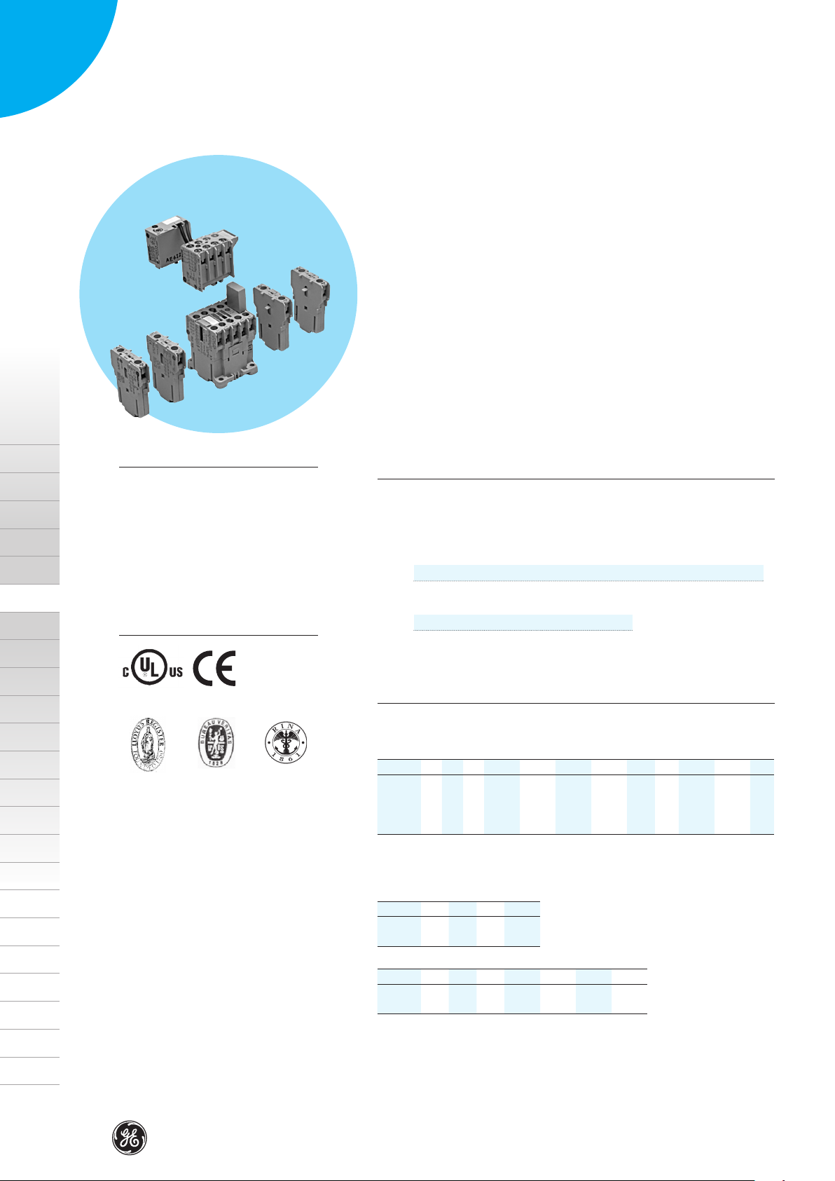
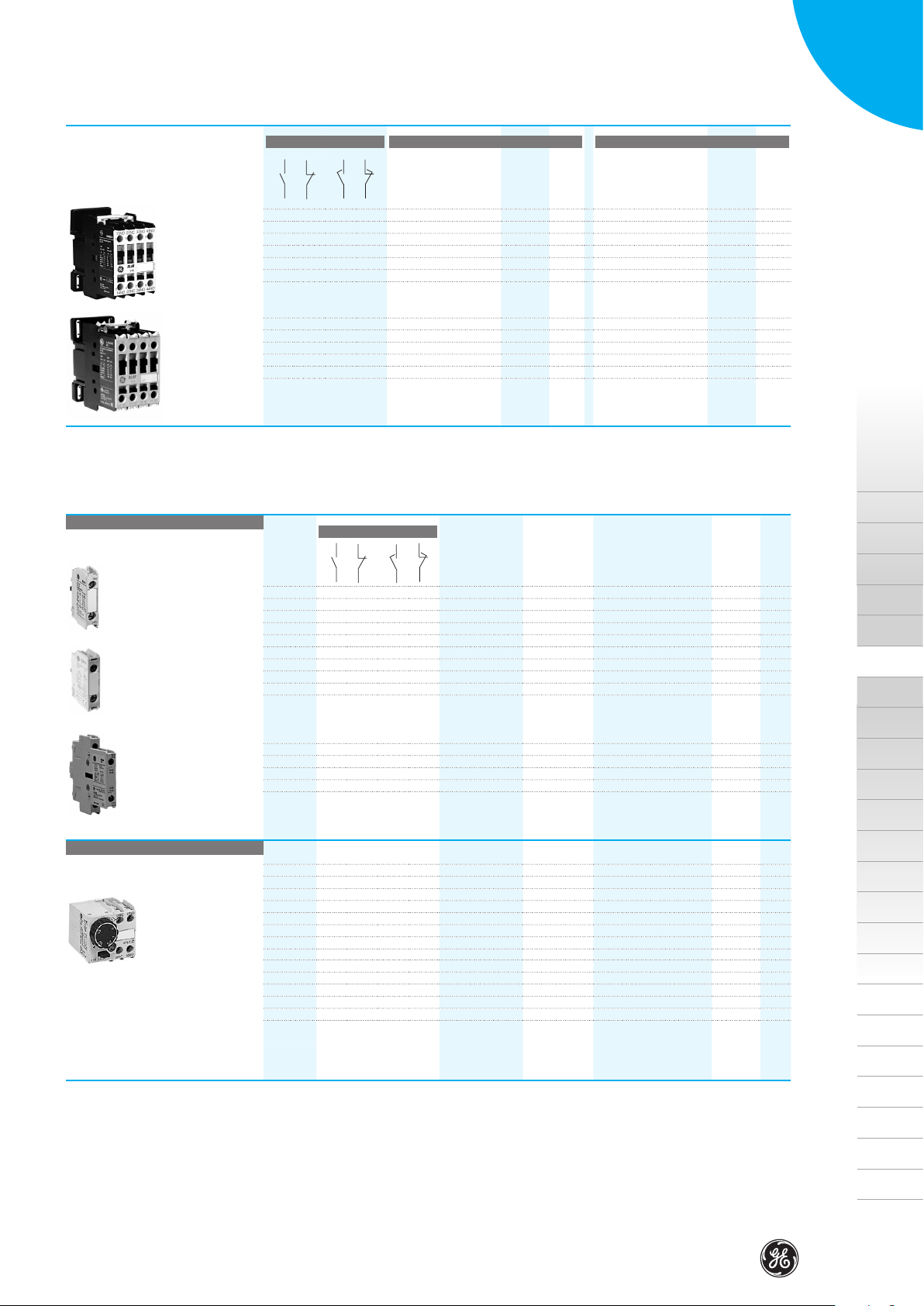
Auxiliary contactors Ith = 16A
• Control circuit: Alternating current up to 600V
Direct current up to 250V
• Terminal numbering in accordance with EN 50011
• Fixing system for rapid and simple mounting by clamping onto standard
35mm DIN rail (EN 50022).
• 6kV rated impulse withstand strength
• Screw and push-on terminals protected against accidental contacts in
accordance with VDE 0106 T.100 and VBG4.
• Printed circuit version.
• Ring terminal version.
• Facility to mount instant or timed auxiliary contact blocks and voltage
supressor blocks.
• Maximum number of auxiliary contacts to add: 6
• Degree of protection IP20 (EN 60529).
• According to IEC/EN 60947-1.
General data
Maximum number of contacts (MCR...) 4
Rated thermal current (Ith) θ ≤ 60º (A) 16
Rated operational voltage (Ue) acc. IEC 60947-1
Insulation voltage (Ui) acc. IEC 60947-1
Utilisation category:
V 110 220/240 380/400 415 440 500 660/690
AC-15
A 6 6 4 4 3 2.5 1.5
V 24 48 110 220
DC-13
A 5 3.5 1.2 0.6
(V) 750
(V) 690
D
E
cULus
Lloyd’s
Register
Auxiliary contacts blocks!page B.3
CE
Bureau
Veritas
Order codes!page B.3
Accessories!page B.4
Technical data!page B.18
Dimensions!page B.24
RINA
Standard voltages
To complete the catalogue number, replace the symbol © by the code
corresponding to the voltage and frequency of the control circuit.
AC Coils
AC 1 2 9 J K M 6 7 N U W Y
50/60Hz
Voltage operating limits of dual-frequency coil:
at 60Hz = 0.85 a 1.1 x Us
at 50Hz = 0.8 a 1.1 x Us for uninterrupted duty (ED=100%), temperature = 40ºC
DC Coils
Voltage
DC Wide Range Coils
Voltage
Operating voltage limits with DC coils:
Standard = 0.8 to 1.1 x Us
Wide range = 0.7 to 1.3 x Us
24 42 48 220-230 240
50 Hz
60Hz
- B D G J
12 24 48 110
- WD WG WI WJ WL WN WS
24 48 72 110 125 220 250
110-115 115-127 380-400 415-440 500
110-120 208-220 277 440 480 600
B.2
Page 3
Series M
•
1
•
2
•
3
•
4
•
1
•
2
•
1
•
2
•
3
•
4
•
1
•
2
•
1
•
2
•
3
•
4
•
1
•
2
•
1
•
2
•
3
•
4
•
1
•
2
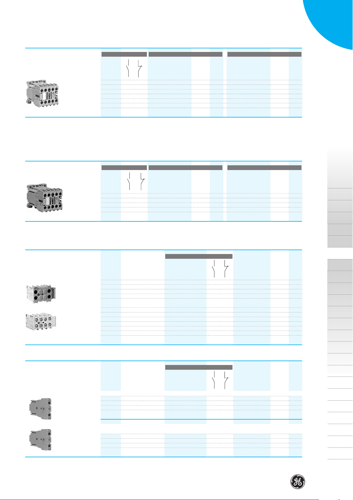
Auxiliary contactors*
Contacts acc. EN 50011 Control circuit: alternating current
Screw terminal
40E 4 0
31E 3 1
22E 2 2
13E 1 3
04E 0 4
(1) To complete the catalogue number, replace the symbol ♦ by the code corresponding to the voltage and
frequency of the control circuit. (see pag. B.8).
(2) Terminal: - with wire 1.5mm
Insulated terminal type B 2.8 x 0.8 with wire 1mm
Faston terminal 1 x 6.3 on request, replace the letter F by H in the catalogue number
(*) Only available order codes listed in the alphabetical index
MCRA040AT ♦
MCRA031AT ♦
MCRA022AT ♦
MCRA013AT ♦
MCRA004AT ♦
2
(1)
Cat. no.
: Ie = 16A - with wire 1mm2: Ie = 10A
Ref. no. Pack.
see bottom see bottom
5
5
5
5
5
2
: Ie = 8A to DIN 46247
Auxiliary contactors interface
Contacts acc. EN 50011 Control circuit: direct current 24V / 1.2W
Operating limits from 19 to 30V
(0.8-1.25 x us
Cat. no. Ref. no. Pack. Cat. no. Ref. no. Pack.
Screw terminal
40E 4 0
31E 3 1
22E 2 2
MCRI040ATD
MCRI031ATD
MCRI022ATD
100530 5
100531 5
100532 5
(3)
Control circuit: direct current
(1)
Cat. no.
MCRC040AT ♦
MCRC031AT ♦
MCRC022AT ♦
MCRC013AT ♦
MCRC004AT ♦
Control circuit: direct current 24V / 2W
Operating limits from 17 to 30V
(0.7-1.25 x Us)
MCRK040ATD
MCRK031ATD
MCRK022ATD
Ref. no. Pack.
100533 10
100534 10
100535 10
10
10
10
10
10
Order codes
(4)
Intro
(3) No possibility of adding instantaneous auxiliary blocks.
(4) Facility to mount instantaneous auxiliary contact block of two contacts (MARN2...)
or two instantaneous auxiliary contact blocks of one contact (MARL1...).
Instantaneous auxiliary contacts blocks
Number of
contacts
Front mounting Screw terminal
Screw terminal
MCRA040AT ♦ (40E)
according to EN 50011
2 60E 20 2 0
2 51E 11 1 1
2 42E 02 0 2
4 80E 40 4 0
4 71E 31 3 1
4 62E 22 2 2
4 53E 13 1 3
4 44E 04 0 4
Instantaneous auxiliary contacts blocks
Number of
contacts
• One or two blocks to cover combinations of 5 or 6 contacts without increasing the height of the basic unit.
Front mounting Screw terminal
MCRA040AT © (40E)
according to EN 50011
1 50E 10 1 0
1 - 01 0 1
Combination with
Combination with
Contacts acc. to EN 50005
Designation
(block marking)
Contacts acc. to EN 50005
Designation
(block marking)
Cat. no. Ref. no. Pack.
MARN220AT
MARN211AT
MARN202AT
MARN440AT
MARN431AT
MARN422AT
MARN413AT
MARN404AT
Cat. no. Ref. no. Pack.
MARL110AT
MARL101AT
100994 10
100993 10
100992 10
100991 10
100990 10
100989 10
100988 10
100987 10
100513 10
100514 10
A
B
C
D
E
• One or two additional blocks, when 9 or 10 contacts are required (combination possible with the front mounting block)
• One or two additional blocks on both sides, to cover up to 8 contacts (combination only possible with lateral blocks)
Screw terminal
1 50E 10 1 0
1 - 01 0 1
2
Insulated terminal type B 2.8 x 0.8 with wire 1mm
: Ie = 8A
MARL110ATS
MARL101ATS
100519 10
100520 10
B.3
Page 4
Series M
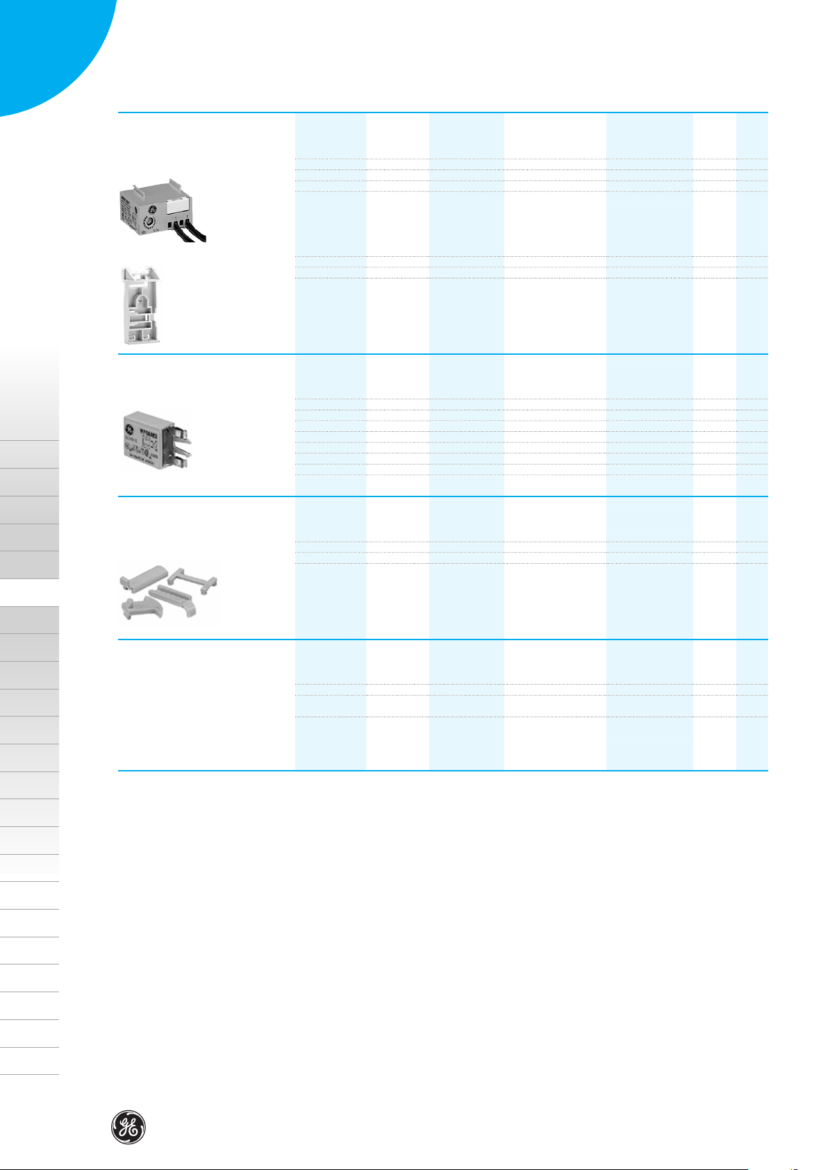
Electronic timer block
Accessories
For use
with
Lateral or front fixing on the contactor
MCR..MC_ ... 0.5 - 60 sec. Delay ON 24 to 250V AC/DC
MCR..MC_ ... 0.2 - 24 sec. Delay ON 24 to 250V AC/DC
Time
Function Ue
Cat. no. Ref. no. Pack.
MREBC10AC2
MREBC20AC2
100541 10
100542 10
Auxiliary minicontactors
Intro
A
B
C
D
Timer fitment
Voltage suppresor block
Mechanical interlock
Identification
For fixing onto 35mm DIN-rail (EN 5022)
MREBC...
For use
with
Connection and (plug-in) fixing onto front of the contactor
MCRA,MC_ ... RC AC 12 to 60V 50/60Hz
MCRA,MC_ ... RC AC 72 to 250V 50/60Hz
MCRC,MC_ ... Diode DC 6 to 250V DC
MCRC,MC_ ... Varistor AC/DC 24-48V
MCRC,MC_ ... Varistor AC/DC 50-127V
MCRC,MC_ ... Varistor AC/DC 130-250V
For use
with
Kit comprising mechanical interlock and contactor jointing parts
MCR, MC_ ...
For use
with
MCR, MC_ ... Sheets of labels (10 sheets of 260 labels each)
MCR, MC_ ... Labelling plate base. Plug-in labelling plate bases
Type Control Ue Cat. no. Ref. no. Pack.
(50 pieces in one pack)
MVB0R
MP0AAE1
MP0AAE2
MP0CAE3
MP0DAE4
MP0DAE5
MP0DAE6
Cat. no. Ref. no. Pack.
MMH0
Cat. no. Ref. no. Pack.
EAT 260
SPR
100543 10
100544 10
100545 10
100546 10
100536 10
204848 10
204849 10
100547 10
100547 10
100549 10
E
B.4
Page 5

Dimensioni
Intro
A
B
Everything is under control
C
D
E
F
G
H
I
X
Page 6
Auxiliary contactors
Intro
A
B
C
Series RL
Standards
IEC/EN 60947-5-1
IEC/EN 60947-1
EN 90947
EN 60947
EN 50005
EN 50011
UL 508
NEMA ICS 1
Approvals/Marking
BS 4794
CENELEC HD410
CENELEC HD420
NFC 63-110
NFC 63-140
CSA C22.2/14
VDE 0660/102
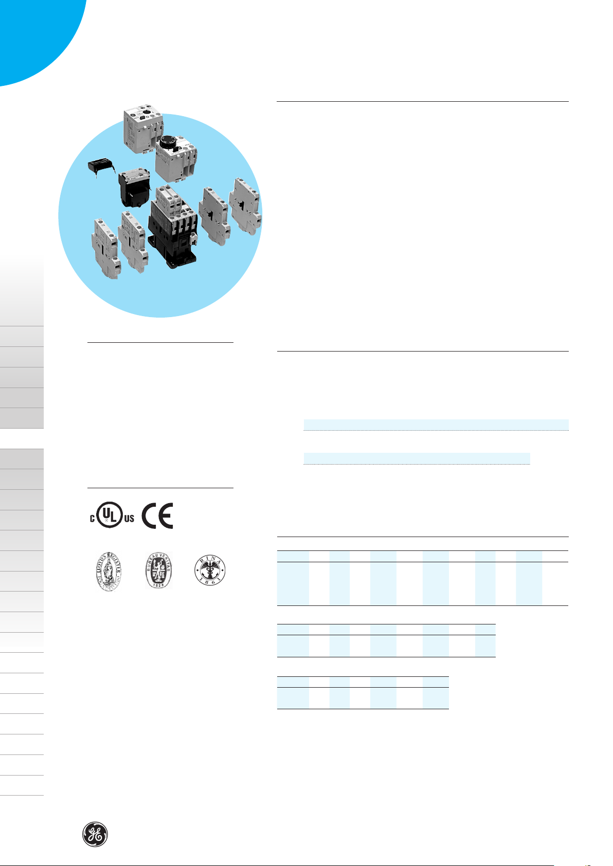
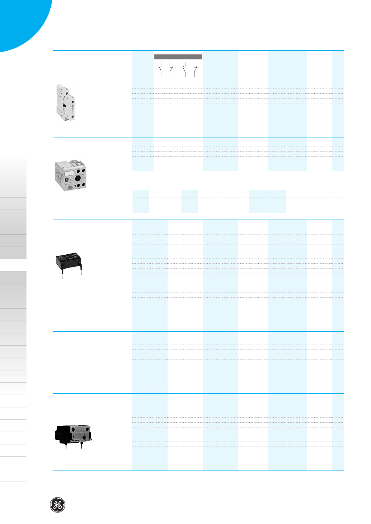
Auxiliary contactors
Ith = 20A
• Control circuit: Alternating current up to 690V
Direct current up to 440V
• Terminal numbering in accordance with EN 50005 and EN 50011
• Fixing system for rapid and simple mounting onto standard 35mm
DIN-rail (EN 50022-35)
• Terminals protected against accidental contact in accordance with
VDE 0106 T.100, VBG4
• Ring terminal versions
• Three coil terminals
• Facility to mount side and/or front instantaneous contact blocks, timed
auxilary contacts, mechanical latch, voltage supressor blocks and interface
modules.
• Degree of protection IP20 (EN 60529)
General data
Maximum number of contacts (RL...) 4
Rated thermal current (Ith) θ ≤ 55º (A) 20
Rated operational voltage (Ue)
Insulation voltage (Ui)
Utilisation category:
V 120 230/220 400/380 440/415 500 690/660
AC-15
A 10 10 6 5 4 2
V 24 48 110 220 440
DC-13
A 6 4 2 0.7 0.35
(V) 1000
(V) 690
D
E
cULus
Lloyd’s
Register
CE
Bureau
Veritas
Order codes!page B.7
Accessories!page B.8
Technical data!page B.9
Dimensions!page B.24
RINA
Standard voltages
AC Coils
- 1 2 9 J K L 6 7 N U Y
50/60Hz
50 Hz
DC Coils
Voltage
DC Wide Range Coils
Voltage
24 42 48 220-230 240
110-115 127 380-400 500
60Hz
- B D G H J K N T
12 24 48 60 110 120-125 220 250
- WD WE WG WI WJ WN
24 33 48 72 110 220
110-120 208 277 440 600
B.6
Page 7
Instantaneous
5
•
•
•
5
•
6
•
1
•
2
•
3
•
4
•
1
•
2
•
•
•
5
•
6
•
1
•
2
•
3
•
4
•
1
•
2
Series RL
Auxiliary contactors*
Contacts
7
8
Screw terminal
4 0 0 0
3 1 0 0
2 2 0 0
0 4 0 0
1 1 1 1
Ring terminal
4 0 0 0
3 1 0 0
2 2 0 0
0 4 0 0
(1) To complete the catalogue number, replace the symbol © by the code corresponding to the voltage and
frequency of the control circuit. (see page B.6).
(*) Only available order codes listed in the alphabetical index
Auxiliary contactors
Number of
contacts
Control circuit: alternating current up to 690V
•
6
•
RL4RA040T ©
RL4RA031T ©
RL4RA022T ©
RL4RA004T ©
RL4RA022G ©
RL4RA040R ©
RL4RA031R ©
RL4RA022R ©
RL4RA004R ©
Contacts Function Time Cat . no.
7
•
Cat. no.
5
•
(1)
Ref. no. Pack.
see bottom see bottom
Control circuit: Direct current up to 440V
Cat. no.
5
5
5
5
5
5
5
5
5
RL4RD040T ©
RL4RD031T ©
RL4RD022T ©
RL4RD004T ©
RL4RD022G ©
RL4RD040R ©
RL4RD031R ©
RL4RD022R ©
RL4RD004R ©
(1)
Ref. no. Pack.
Ref. no.
10
10
10
10
10
10
10
10
10
Pack.
Order codes
Intro
Frontal mounting Screw terminal
Ring terminal
Side mounting Screw terminal
Pneumatic timer blocks
Frontal mounting Screw terminal
Ring terminal
Sealing cover protection for pneumatic timer
6
8
1 1 0 0 0
1 0 1 0 0
1 0 0 1 0
1 0 0 0 1
1 1 0 0 0
1 0 1 0 0
2 2 0 0 0
2 1 1 0 0
2 0 2 0 0
2 0 0 1 1 Delayed ON 0.1 - 30 sec.
2 0 0 1 1 Delayed ON 1 - 60 sec.
2 0 0 1 1 Delayed OFF 0.1 - 30 sec.
2 0 0 1 1 Delayed OFF 1 - 60 sec.
2 0 0 1 1 Delayed ON 0.1 - 30 sec.
2 0 0 1 1 Delayed ON 1 - 60 sec.
2 0 0 1 1 Delayed OFF 0.1 - 30 sec.
2 0 0 1 1 Delayed OFF 1 - 60 sec.
BCLF10
BCLF01
BCLF10G
BCLF01G
BCRF10
BCRF01
BRLL20
BRLL11
BRLL02
BTLF30C
BTLF60C
BTLF30D
BTLF60D
BTRF30C
BTRF60C
BTRF30D
BTRF60D
BTLFX
104700 10
104701 10
104702 10
104703 10
108901 10
108902 10
104704 10
104705 10
106622 10
104709 10
104710 10
104711 10
104712 10
108903 10
108904 10
108905 10
108906 10
113001 5
A
B
C
D
E
B.7
Page 8
Series RL
•
•
•
5
•
6
•
1
•
2
•
3
•
4
•
1
•
2
Mechanical interlock Mechanical
Accessories
Number of
contacts
- - - - -
Mechanical / electrical
2 0 2 - -
Contacts Cat. no.
5
7
•
•
6
8
BELA
BELA02
Ref. no.
104723 5
104724 5
Pack.
Auxiliary contactors
Intro
A
B
C
D
Mechanical latch blocks
Transient voltage
supressor block
Frontal mounted to the contactor
(1) To complete the catalogue number, replace the symbol © by the code corresponding to the voltage and
frequency of the control circuit.
© D G J N U
50Hz 24, 32 42, 48 110, 115, 120, 127 220, 230, 240 380, 400, 415, 440, 480
60HZ 24, 32 48, 60 110, 115, 120, 127 208, 220, 240, 277 380, 400, 415, 440, 480
DC 24, 32, 36 42, 48 110, 120, 125 220, 230, 240, 250 440
For use with Type Control circ. Ue Cat. no.
Directly connected parallel to the coil terminals,
allows simultaneous use with auxiliary contact blocks.
RL4RA... R/C AC 12V ... 48V
RL4RA... R/C AC 50V ... 127V
RL4RA... R/C AC 130V ... 250V
RL4RD... Diode DC
RL4RA..., RL4RD... Varistor AC / DC 24V ... 48V
RL4RA..., RL4RD... Varistor AC / DC 50V ... 127V
RL4RA..., RL4RD... Varistor AC / DC 130V ... 250V
RL4RA..., RL4RD... Varistor AC / DC 277V ... 500V
RL4RA..., RL4RD...
RMLF ©
BSLR2G
BSLR2K
BSLR2R
BSLDZ
BSLV3G
BSLV3K
BSLV3R
BSLV3U
see bottom 20
Ref. no.
104713 10
104714 10
104715 10
104719 10
104720 10
104721 10
104722 10
110836 10
Pack.
E
Identification
Electronic timer
module
B.8
For use with Cat. no.
RL4RA..., RL4RD... Sheets of labels (10 sheets of 260 labels each)
RL4RA..., RL4RD... Labelling plate base. Plug-in labeling plate bases
For use with Control circuit Function Time Cat. no.
Directly connected parallel to the coil terminals,
allows simultaneous use with auxiliary contact blocks.
RL4... 24-250V AC/DC Delayed ON 0.1 - 2 sec.
RL4... 24-250V AC/DC Delayed ON 1.5 - 45 sec.
RL4... 24-250V AC/DC Delayed OFF 0.1 - 2 sec.
RL4... 24-250V AC/DC Delayed OFF 1.5 - 45 sec.
(50 pieces in one pack)
EAT 260
BETL02C
BETL45C
BETL02D
BETL45D
SPR
Ref. no.
100548 1
100549 1
Ref. no.
113602 5
113603 5
113604 5
113605 5
Pack.
Pack.
Page 9

Technical data
Series M
General
Maximum number of contacts (MCR...) 4
Rated thermal current (Ith) θ ≤ 60º 16A
Rated operational voltage (Ue) acc. IEC 60947.1 690V
Insulation voltage (Ui) acc. IEC 60947.1 750V
Conformity to standards
IEC / EN 60947-5-1 IEC / EN 60947-1 BS 4794
EN 50002 EN 50005 EN 50011
NFC 63-110 NFC 63-140 CENELEC HD 420
CSA C22.2/14 VDE 0660 UL 508
Approvals
cULus DEMKO NEMKO
SEMKO SETI RINA
Lloyd’s Register Bureau Veritas CE
Ambient conditions
Storage temperature -55ºC to +80ºC
Operation temperature -40ºC to +60ºC
Altitude up to 3000m Nominal values
from 3000 to 4000m 90%Ie 80%Ue
from 4000 to 5000m 80%Ie 75%Ue
Climatic resistance (IEC 68-2)
Continuous tests 40 / 125 / 56
Cold (72h)
Temperature -40ºC
Dry heat (96h)
Temperature +125ºC
Relative humidity < 50%
Humid heat (56 days)
Temperature +40ºC
Relative humidity 95%
Cyclical tests (6 cycles)
Humid heat
First half-cycle (12h)
Low temperature +25ºC
Relative humidity 93%
Second half-cycle (12h)
Low temperature +55ºC
Relative humidity 95%
Shock resistance (IEC 68-2-27)
Continously closed (at 0.8Us)
Admissible acceleration 25 g
Impulse duration 11ms
Continously opened (no voltage)
Admissible acceleration 20 g
Impulse duration 11ms
Mounting positions
With the same pick-up and drop-out voltage
With the same rated power
-7% of connection voltage
+4% of disconnection voltage
With the same rated power
-7% of connection voltage
+4% of disconnection voltage
With the same rated power
Terminal capacity
Terminal with screw M3.5 Tightening torque
(with pozidrive head and safety flange) 0.8 Nm - 7 Lb-in
Solid wire mm
Flexible wire without terminal mm
Flexible wire with terminal with cap mm
mm
Ring terminal cap 0.8 Nm - 7 Lb/in
Fast-on 2.8 - 2 insulated terminals mm
Terminal for printed circuit (Ø of PCB hole) 1.8mm
Ring terminal cap 7.8mm
Fork terminal cap 6.5mm
2
0.75 to 2 x 2 w.
2
0.75 to 2.5 x 2 w.
2
0.75 to 2.5 x 1 w
2
0.75 to 1 x 2 w
2
1 x 2 w.
Coil Terminal capacity and
tightening torque
Tightening torque 0.8Nm - 7Lb/in
Solid wire (mm
Flexible wire without terminal (mm
Flexible wire without terminal with cap (mm
2
) 0.75 to 2x2
2
) 0.75 to 2.5x2
2
) 0.75 to 2.5x21
Technical data
Intro
A
B
C
D
E
Vibration resistance (IEC 68-2-6)
Continously closed (at 0.8Us)
Admissible acceleration 15 g
Sweep between 10 - 200Hz
Continously opened (no voltage)
Admissible acceleration 5 g AC - 3.5g DC
Sweep between 10 - 200Hz
B.9
Page 10

Auxiliary minicontactors
Intro
A
B
C
Series M
Control circuit
MCRA... MCRC... MCRC... MCRI...
Rated insulation voltage (Ui) (V) 750 750 750 750 750
Standard voltages (Us)
50Hz (V) 24...690 – – – –
60Hz (V) 6...600 – – – –
DC (V) – 6...440 12...440 24 24
(1)
Voltage
Operating limits xUs 0.8...1.1 0.8...1.1 0.7...1.3 0.8...1.25 0.7...1.25
Drop-out xUs 0.35...0.55 0.15...0.3 0.15...0.3 0.15...0.3 0.13...0.35
Consumption
Pick-up (VA) 26 – – – –
Seal (VA) 4 – – – –
DC (W) – 3 4 1.2 2
Power factor
Pick-up (cos ϕ) 0.8 – – – –
Seal (cos ϕ) 0.35 – – – –
Power dissipation (W) 1.4 3 4 1.2 2
Opening and closing times
Values between ± %Us % +10...-20 +10...-20 +30...-30 +25...-20 +25...-20
Time at energisation NO
Time at de-energisation NC
Time at energisation NC
Time at de-energisation NO
Values at Us
Time at energisation NO
Time at de-energisation NC
Time at energisation NC
Time at de-energisation NO
Maximum time without voltage (ms) 3 3 3 3 3
(without effecting the closed magnetic circuit)
Mechanical endurance
Monofrequency x10
Dual-frequency x10
DC x10
Maximum rate (no load)
Monofrequency n° ops./h 9000 – – – –
Dual-frequency n° ops./h 3600 – – – –
DC n° ops./h – 9000 9000 9000 9000
(ms) 6...13 22...36 17...28 30...70 20...50
(ms) 8...16 9...12 9...12 9...16 9...16
(ms) 5...11 18...27 12...25 20...45 18...35
(ms) 6...13 5...7 5...7 5...9 5...9
(ms) 7...12 24...27 19...23 25...45 25...40
(ms) 8...16 9...11 9...11 9...16 9...16
(ms) 6...10 20...26 15...21 25...35 20...30
(ms) 6...13 5...8 5...8 5...9 5...9
6
ops. 15 – – – –
6
ops. 10 – – – –
6
ops. – 10 10 10 10
MCRK...
D
E
Contact sequence (distance in mm)
Auxiliary contact
NO
0 1.95 3.5
Auxiliary contact MCR.....
0 2.1 3.5
Auxiliary MAR.....
contact
blocks
Open
Auxiliary contact
NC
0 1.2 3.5
0 0.7 3.5
Closed
B.10
Page 11

Series M
.
.
.
.
.
.
.
.
.
.
.
.
.
.
.
.
.
.
.
.
.
Internal auxiliary contacts
MCR.....
Rated insulation voltage (Ui) acc. IEC 60947-1 750V
Rated thermal current (Ith) θ ≤ 60ºC
Making capacity (r.m.s.) acc. IEC 60947-5
AC-15 Ue ≤ 440V 50/60Hz 160A
DC-13 Ue ≤ 220V DC 3A
Breaking capacity (r.m.s.) acc. IEC 60947-5
AC-15 Ue ≤ 440V 50/60Hz 106A
DC-13 (L/R = 100 ms) Ue ≤ 220V DC 1.2A
Ue = 110V DC 3A
Ue = 48V DC 10A
Rated voltage and rated current Ue-Ie
AC-15 according to IEC 947 110/120V - 6A
220/240V - 6A
380/400V - 4A
415/440V - 4A
500V - 2.5A
660/690V - 1.5A
according to UL, CSA A600
DC-13 according to IEC 24V - 5A
48V - 3.5 A
110V - 1.2A
220V - 0.6A
440V - 0.25A
according to UL, CSA P600
Minimum operational power (operational safety) 5mA, 17V
Short-circuit protection 10A
(max.class gl fuse without welding)
Insulation resistance
between contacts > 10MΩ
between input and output > 10MΩ
Guaranted no overlap of the contacts
Space 1.1mm
minimum time > 2ms
Impedance 2.3mΩ
Terminal capacity Same as
main circuit
(1)
16A
between contacts and earth
> 10MΩ
Tripping characteristics Ie/ue
Inductive circuit. DC-13 L/R ≤ 100 ms
DC
Electrical endurance 10
Inductive circuit. DC-13 L/R ≤ 15ms
DC
Electrical endurance 10
6
ops.
6
ops.
(1) 1 pole in series
(2) 2 poles in series
(3) 3 poles in series
Technical data
Intro
A
B
Tripping characteristics (AC)
AC-15
AC
Electrical endurance
DC
Inductive circuit DC-13 L/R ≤ 1ms
Electrical endurance 10
6
ops.
(1) 1 pole in series
(2) 2 poles in series
(3) 3 poles in series
(1) 1 pole in series
(2) 2 poles in series
(3) 3 poles in series
C
D
E
B.11
Page 12

Series M
.
.
.
.
.
.
.
.
.
.
.
.
.
.
.
.
.
.
.
.
.
Auxiliary minicontactors
Intro
A
B
C
D
E
External auxilary contact blocks
MARN..., MARL...
Rated insulation voltage (Ui) acc. IEC 60947-1 750V
Rated thermal current (Ith) θ ≤ 60ºC
Making capacity (r.m.s.) acc. IEC 60947-5
AC-15 Ue ≤ 220V 50/60Hz 73A
Ue = 380V 50/60Hz 38A
Ue = 690V 50/60Hz 22A
DC-13
Ue = 220V DC 1A
Ue = 440V DC 0.6A
Breaking capacity (r.m.s.) acc. IEC 60947-5
AC-15 Ue ≤ 220V 50/60Hz 73A
Ue = 380V 50/60Hz 38A
Ue = 690V 50/60Hz 22A
DC-13 L/R = 100 ms Ue ≤ 100V DC 2A
Ue = 220V DC 0.8A
Ue = 440V DC 0.4A
Rated voltage and rated current Ue-Ie
AC-15 according to IEC 60947 110/120V - 6A
220/240V - 6A
380/400V - 3A
415/440V - 3A
500V - 1A
660/680V - 1A
according to UL, CSA A600
DC-13 according to IEC 60947 24V - 4A
48V - 2A
110V - 0.7A
220V - 0.3A
440V - 0.1A
according to UL, CSA Q600
Minimum operational power (operational safety) 5mA, 17V
Short-circuit protection 10A
(max.class gl fuse without welding)
Insulation resistance
between contacts > 10MΩ
between input and output > 10MΩ
Guaranteed no overlap of the contacts
Space 0.5mm
minimum time > 2ms
Impedance 2.4mΩ
Terminal capacity Same as
main circuit
L/R = 100 ms
Ue ≤ 100V DC 2.6A
(1)
10A
between contacts and earth
> 10MΩ
Tripping characteristics Ie/ue
Inductive circuit. DC-13 L/R ≤ 100ms
DC
Electrical endurance 10
Inductive circuit. DC-13 L/R ≤ 15ms
DC
Electrical endurance 10
DC
Inductive circuit. DC-13 L/R ≤ 1ms
Electrical endurance 10
6
ops.
6
ops.
6
ops.
(1) 1 pole in series
(2) 2 poles in series
(3) 3 poles in series
(1) 1 pole in series
(2) 2 poles in series
(3) 3 poles in series
B.12
Tripping characteristics (AC)
AC-15
AC
Electrical endurance
(1) 1 pole in series
(2) 2 poles in series
(3) 3 poles in series
Page 13

Electronic timer block
MREBC...
Rated insulation voltage (Ui) 750V
Rated thermal current (Ith) θ ≤ 60ºC
Standard voltages (AC y DC) 24 to 250V
Operation limits 0.80 to 1.1 Us
(0.85 to 1.1 Us at 12V)
Voltage drop < 3V
Maximum load current at
20ºC 0.9A
40ºC 0.72A
60ºC 0.55A
Minimum load for safe operation > 10mA
Maximum current (peak) 10A for 40ms
Leakage current at 220V < 5mA
Operational current
AC-15 0.7A
DC-13 0.9A
Timing range (delay ON) 0.5 to 60s (± 6s)
Rearragement time < 100ms
Repeatibility (accuracy) ± 1%
Ambient temperature
Storage from –55 up to + 80ºC
Operation from –5 up to + 60ºC
Degree of protection IP20
Mounting position any
Terminals : 2 free cables 1mm
250mm
(1)
0.55V
2
(AWG 17)
Series M
Technical data
Intro
MREBC _ 0AC2
A
B
C
D
E
B.13
Page 14

Series M
Auxiliary minicontactors
Intro
Terminal numbering
Auxiliary contactors. According to EN 50011
MCR_040_ _ _ MCR_031_ _ _
MCR_022_ _ _ MCR_013_ _ _
MCR_004_ _ _
Auxiliary contact blocks
According to EN 50005 & EN 50011
MARL110A _ MARL101A _ MARL110A _ S
MARL101A _ S MARN220A _ MARN211A _
MARN202A _ MARN440A _ MARN431A _
MARN422A _ MARN413A _ MARN404A _
A
B
C
D
E
Transient voltage suppressor block
MP0AAE _ MP0CAE3
MP0DAE4
B.14
Page 15

Series M
Terminal numbering in accordance with EN 50011
By combining other basic auxiliary contactors with auxiliary contact blocks MAR..., it is possible to obtain other combinations, and positions of
contacts which are not covered by the table. But in all cases the maximum number of auxiliary contacts should be ten.
Type E
Standard contact combination in
which the interchangeability of the
devices does not affect the cabling
or the diagram. Specifies a particular
contact numbering and positioning.
Type E
Final structure of
the combination
Auxiliary contacts
Combination
Description
40E
31E
22E
13E 1 3
04E 0 4
60E 6 0
51E 5 1
42E 4 2
80E 8 0
71E 7 1
62E 6 2
NO NC
4 0
3 1
2 2
Auxiliary contactor
+ Auxiliary contact blocks to be added
MCRA040A..
MCRA031A..
MCRA022A..
MCRA013A..
MCRA004A..
MCRA040A..
+ MARN220A..
MCRA040A..
+ MARN211A..
MCRA040A..
+ MARN202A..
MCRA040A..
+ MARN440A..
MCRA040A..
+ MARN431A..
MCRA040A..
+ MARN422A..
Technical data
Intro
A
B
C
D
53E 5 3
44E 4 4
50E 5 0
41E 4 1
32E 3 2
23E 2 3
14E 1 4
05E 0 5
MCRA040A..
+ MARN413A..
MCRA040A..
+ MARN404A..
MCRA040A..
+ MARL110A..
MCRA031A..
+ MARL110A..
MCRA022A..
+ MARL110A..
MCRA013A..
+ MARL110A..
MCRA013A..
+ MARL101A..
MCRA004A..
+ MARL101A..
E
B.15
Page 16

Series M
Terminal numbering in accordance with EN 50011 (continued)
By combining other basic auxiliary contactors with auxiliary contact blocks MAR..., it is possible to obtain other combinations, and positions of
contacts which are not covered by the table. But in all cases the maximum number of auxiliary contacts should be ten.
Type Z
Contact combination the same as
Type E. Interchangeability of the devices may affect the cabling and the
diagram. Neither contact numbering
nor positioning are retained.
Type X
Contact combination the same as
Type E. Interchangeability of the devices may affect the cabling but not
the diagram.The contact numbering
is maintained but not their position.
Type Y
Contact combination which differs
from Type E, although it is obtained
by a combination of devices provided for this Type E.
Auxiliary minicontactors
Intro
A
B
C
D
E
Type Z
Type X
Type Y
Final structure of
the combination
Auxiliary contacts
Combination
Description
60Z
51Z 5 1
42Z 4 2
100Z 10 0
55Z 5 5
80X 8 0
71X 7 1
62X 6 2
53X 5 3
44X 4 4
91X 9 1
82X 8 2
73X 7 3
64X 6 4
42Y 4 2
NO NC
6 0
Auxiliary contactor
+ Auxiliary contact blocks to be added
MCRA040A..
+ MARL110A.. + MARL110A..
MCRA040A..
+ MARL110A.. + MARL101A..
MCRA040A..
+ MARL101A.. + MARL101A..
MCRA040A..
+ MARN440A.. + MARL110A..S
+ MARL110A..S
MCRA040A..
+ MARN413A.. + MARL101A..S
+ MARL101A..S
MCRA040A..
+ MARL110A.. + MARL110A..
+ MARL110A..S + MARL110A..S
MCRA040A..
+ MARL110A.. + MARL101A..
+ MARL110A..S + MARL110A..S
MCRA040A..
+ MARL110A.. + MARL101A..
+ MARL101A..S + MARL110A..S
MCRA040A..
+ MARL110A.. + MARL101A..
+ MARL101A..S + MARL101A..S
MCRA040A..
+ MARL101A.. + MARL101A..
+ MARL101A..S + MARL101A..S
MCRA040A..
+ MARN431A.. + MARL110A..S
+ MARL110A..S
MCRA040A..
+ MARN431A.. + MARL101A..S
+ MARL110A..S
MCRA040A..
+ MARN422A.. + MARL101A..S
+ MARL110A..S
MCRA040A..
+ MARN422A.. + MARL101A..S
+ MARL101A..S
MCRA031A..
+ MARL110A.. + MARL101A..
B.16
33Y 3 3
42Y 4 2
33Y 3 3
53Y 5 3
44Y 4 4
MCRA022A..
+ MARL110A.. + MARL101A..
MCRA031A..
+ MARN211A..
MCRA022A..
+ MARN211A..
MCRA031A..
+ MARN422A..
MCRA022A..
+ MARN422A..
Page 17

Dimensional drawings
.
.
.
.
.
Series M
Auxiliary contact blocks. Front mountingAuxiliary minicontactors
Slotted screw Slotted screw
MCRA_ _ _ AT◆
.
.
0.170kg
MCRC_ _ _ AT◆
MCRI _ _ _ ATD
MCRK_ _ _ ATD
.
.
0.210kg
0.225kg
0.225kg
.
MARN2 _ _AT
MARN4 _ _AT
Electronic timer blockAuxiliary contact blocks. Lateral mounting
Slotted screw
MARL_ _ _AT, ATS
(1) AC-control.
(2) DC-control
0.013kg
.
MREBC _0AC2
(1) Frontal mounting
(2) Lateral mounting
0.040kg
0.025kg
0.040kg
Dimensions
Intro
A
Voltage suppressor block
MP0A_AE_
MP0C_AE3
0.010kg
0.010kg
B
C
D
E
Dimensions in mm (inch = mm x 0.03937) - Weight in kg (lb = kg x 2.2046 )
B.17
Page 18

Series RL
Auxiliary Contactors
Intro
A
B
C
D
E
General
Maximum number of contacts 4
Rated thermal current (Ith) θ < 55ºC 20A
Rated operational voltage (Ue) 690V
Insulation voltage (Ui) 1000V
Conformity to standards
IEC / EN 60947-1 IEC / EN 60947-5-1 ASE 1025
EN 50005 EN 50011 VDE 0660 / 102
NFC 63-110 NFC 63-140
CENELEC HD 410 CENELEC HD 420
NEMA ICS 1 CSA C22.2/14
UL 508 BS 4794
Approvals/Marking
cULus DEMKO NEMKO
SEMKO FI CE
Lloyd’s Register Bureau Veritas
Ambient conditions
Storage temperature -55ºC to +80ºC
Operation temperature -40ºC to +60ºC
Altitude up to 3000m Nominal values
from 3000 to 4000m 90%Ie 80%Ue
from 4000 to 5000m 80%Ie 75%Ue
Climatic resistance (IEC 68-2)
Continuous tests 40 / 125 / 56
Cold (72h)
Temperature -40ºC
Dry heat (96h)
Temperature +125ºC
Relative humidity < 50%
Humid heat (56 days)
Temperature +40ºC
Relative humidity 95%
Cyclical tests (6 cycles)
Humid heat
First half-cycle (12h)
Low temperature +25ºC
Relative humidity 93%
Second half-cycle (12h)
Low temperature +55ºC
Relative humidity 95%
Mounting positions
With the same pick-up and drop-out voltage
With the same rated power
Control circuit
RL4RA...
Rated insulation voltage Ui (V) 1000 1000 1000
Standard voltages Us
50Hz (V) 24 ... 690 – –
60Hz (V) 24 ... 600 – –
DC (V) – 12 ... 440 12 ... 440
(1)
Voltage
Operating limits xUs 0.8 ... 1.1 0.8 ... 1.1 0.7 ... 1.3
Pick-up xUs 0.65 ... 0.75 0.45 ... 0.65 0.45 ... 0.55
Seal xUs 0.4 ... 0.55 0.15 ... 0.3 0.15 ... 0.3
Consumption
AC Magnetic circuit closed (VA) 6 – –
Magnetic circuit open (VA) 45 – –
DC Magnetic circuit closed (W) – 5.5 6.5
Magnetic circuit open (W) – 5.5 6.5
Power dissipation
Power factor
Magnetic circuit closed cos ϕ 0.34 – –
Magnetic circuit open cos ϕ 0.82 – –
Opening and closing times
at 0.8 to 1.1 Us
Closing time NO
Opening time NO (ms)
at Us
Closing time NO
Opening time NO (ms)
Mechanical endurance 10
Maximum rate no load ops./h 9000 3600 3600
(W) 2.4 5.5 6.5
(ms) 6 ... 25 35 ... 65 25 ... 65
(ms) 8 ... 20 35 ... 45 25 ... 55
6 ... 13 6 ... 13 6 ... 13
6 ... 13 7 ... 12 6 ... 13
6
ops 15 15 15
RL4RD...
RL4RD...W
B.18
Contact sequence (distance in mm)
Auxiliary contact
NO
Auxiliary RL4R......◆
contactor
RL4R...G◆
Auxiliary BC_F.../
contact BRLL...
blocks
BCLF...G
0 3.35 4.7
0 1.85 4.7
0 3.3 4.7
0 1.8 4.7
Auxiliary contact
NC
0 1.3 4.7
0 2.8 4.7
0 1.3 4.7
0 2.8 4.7
Open
Closed
Page 19

Series RL
.
.
.
Internal auxiliary contacts
RL4.....
Rated insulation voltage (Ui) acc. IEC 60947-5 1000V
Rated thermal current (Ith) θ < 55ºC 20A
Making capacity (r.m.s.) acc. IEC 60947-5
AC-15 Ue ≤ 400V, 50/60Hz 250A
DC-13 Ue ≤ 220V DC 250A
Breaking capacity (r.m.s.) acc. IEC 60947-5
AC-15 Ue ≤ 400V, 50/60Hz 250A
DC-13 Ue ≤ 220V DC 2A (4A with 2
contacts in series
Ue ≤ 110V DC 7A (12A with 2
contacts in series)
Ue ≤ 48V DC 10A (18A with 2
contacts in series)
Rated voltage and rated current Ue-Ie
AC-15 according to IEC 110/120V - 10A
220/240V - 10A
380/400V - 6A
415/440V - 5A
500V - 4A
660/690V - 2A
according to UL, CSA A600
DC-13 according to IEC 24V - 6A
48V - 4 A
110V - 2A
220V - 0.7A
440V - 0.35A
according to UL, CSA P600
Electrical endurance 1 x 10
Minimum operational voltage (operational safety) 17V
Minimun operational current 5mA
Short-circuit protection
max. fus. class gL fuse 20A
without welding 10A
Insulation resistance
between contacts > 10mΩ
between contacts and earth > 10mΩ
between input and output > 10mΩ
Guaranteed no overlap between NO and NC contacts
space 1.3mm
minimum time 1.5ms
Impedance 1.28mΩ
6
ops.
Terminal capacity
Solid, stranded and finely stranded mm2 2 x 0.5 to 6
without end sleeve
Finely stranded with end sleeve mm
AWG wires, solid and stranded mm
Tightening torque 1.1 Nm / 10 Lb.in
Ring terminals 1.6 Nm / 15 Lb.in
2
2 x 1 to 6
2
2 x 20 to 12
Instantaneous auxiliary contact blocks
BCLF../BCRF../BRLL..
Rated insulation voltage (Ui) acc. IEC 60947-5 1000V
Rated thermal current (Ith) θ < 55ºC 10A
Making capacity (r.m.s.) acc. IEC 60947-5
AC-15 Ue ≤ 440V, 50/60Hz 90A
DC-13 Ue ≤ 220V DC 90A
Breaking capacity (r.m.s.) acc. IEC 60947-5
AC-15 Ue ≤ 400V, 50/60Hz 60A
DC-13 Ue ≤ 220V DC 0.95A
Rated voltage and rated current Ue-Ie
AC-15 according to IEC 110/120V - 6A
220/240V - 6A
380/400V - 4A
415/440V - 3.5A
500V - 2.5A
660/690V - 1.5A
according to UL, CSA A600
DC-13 24V - 4A
48V - 2A
110V - 0.7A
220V - 0.3A
415/440V - 0.15A
according to UL, CSA Q600
Electrical endurance 1 x 10
Minimum operational voltage (operational safety) 17V
Minimun operational current 5mA
Short-circuit protection (without welding) gL 10A
Insulation resistance
between contacts > 10mΩ
between contacts and earth > 10mΩ
between input and output > 10mΩ
Guaranteed no overlap between NO and NC contacts
Space 1.3mm
minimum time 1.5ms
Impedance of the contacts 1.28mΩ
6
ops.
Terminal capacity
Solid, stranded and finely stranded mm2 2 x 0.5 to 2.5
without end sleeve 2 x 2.5 to 4
Finely stranded with end sleeve mm
2 x 2.5 to 4
AWG wires, solid and stranded mm
Tightening torque 0.8 Nm / 7 Lb.in
Ring terminals 0.8 Nm / 7 Lb.in
2
2 x 0.5 to 2.5
2
2 x 20 to 10
Technical data
Intro
A
B
C
D
E
Coil Terminal capacity and
tightening torque
Tightening torque 0.8Nm - 7Lb/in
Solid wire (mm
Flexible wire without terminal (mm
Flexible wire without terminal with cap (mm
2
) 0.75 to 2x2
2
) 0.75 to 2.5x2
2
) 0.75 to 2.5x21
B.19
Page 20

Series RL
.
.
Auxiliary Contactors
Intro
A
B
C
D
Timed auxiliary contact blocks
BTLF... / BTRF...
Rated insulation voltage (Ui) acc. IEC 60947-5 1000V
Rated thermal current (Ith) θ < 55ºC 10A
Making capacity (r.m.s.) acc. IEC 60947-5
AC-15 Ue ≤ 440V, 50/60Hz 90A
DC-13 Ue ≤ 220V DC 90A
Breaking capacity (r.m.s.) acc. IEC 60947-5
AC-15 Ue ≤ 400V, 50/60Hz 60A
DC-13 Ue ≤ 220V DC 0.95A
Rated voltage and rated current Ue-Ie
AC-15 according to IEC 110/120V - 6A
220/240V - 6A
380/400V - 4A
415/440V - 3.5A
500V - 2.5A
660/690V - 1.5A
according to UL, CSA A600
DC-13 according to IEC 24V - 4A
48V - 2A
110V - 0.7A
220V - 0.3A
415/440V - 0.15A
according to UL, CSA Q600
Electrical endurance 1 x 10
Minimum operational voltage (operational safety) 17V
Minimum operational current 5mA
Short-circuit protection (without welding) gL 10A
Insulation resistance
between contacts > 10mΩ
between contacts and earth > 10mΩ
between input and output > 10mΩ
Guaranteed no overlap between NO and NC contacts
space 1.3mm
minimum time 1.5ms
Timing
(Ambient temperature between – 25 and + 55ºC)
Accuracy ± 5%
Loss of accuracy after 0.5 x 10
Loss of accuracy per rise ºC (0 - 55ºC) + 0.75 % per °C
Impedance of the contacts 1.28mΩ
Mechanical endurance 5 x 10
Peak current
during 1 s. 50A
during 0.1 s. 100A
6
ops. + 20%
6
ops.
6
ops.
Mechanical latch blocks
RMLF.....
Rated insulation voltage(Ui) 1000V
Standard voltages (Us); 50-60Hz and direct current 24 ... 690V
Operating limits 0.75 to 1.1 xUs
Consumption for unlatching (auto cut-out) 210W /VA (24-72V)
130W /VA (110-440V)
Unlatching control
Electrical Min.impuls 10 ms
Maintained auto
cut-out by integral
contact 55-56
(only AC slots)
Manual By local (0)
push-button
Contactor control
Electrical Min.impuls 40 ms
Manual By local (I)
push-button
Mechanical endurance RL4 3 x 10
(1)
6
(1200ops./h
Terminal capacity
Solid, stranded and finely stranded mm2 2 x 0.5 to 2.5
without end sleeve 2 x 2.5 to 4
Finely stranded with end sleeve mm
2 x 2.5 to 4
AWG wires, solid and stranded mm
Tightening torque 0.8 Nm / 7 Lb.in
2
2 x 0.5 to 2.5
2
2 x 20 to 10
E
B.20
Terminal capacity
Solid, stranded and finely stranded (mm2) 2 x 0.5 to 2.5
without end sleeve 2 x 2.5 to 4
Finely stranded with end sleeve (mm
2 x 2.5 to 4
AWG wires, solid and stranded (mm
Tightening torque 0.8 Nm / 7 Lb.in
Ring terminals 0.8 Nm / 7 Lb.in
2)
2)
2 x 0.5 to 2.5
2 x 20 to 10
Page 21

Terminal numbering
Series RL
Auxiliary contactors
RL4R_040_ _ RL4R_031_ _
RL4R_022_ _ RL4R_004_ _
RL4R_022G_
Auxiliary contact blocks. Front mounting
BC_F10 BCLF01GBC_F01 BCLF10G
Mechanical (-/electrical) interlock
BELA, BEL BELA02, BEL02
Mechanical latch block
RMLF
AC AC/DC
Voltage suppressor blocks
BSLR2 BSLDZ BSLV3
Technical data
Intro
A
Auxiliary contact blocks. Lateral mounting
BRLL20 BRLL11
Pneumatic timer blocks
BT_F_C BT_F_D
Electronic timer blocks
BETL_ _C BETL_ _D
B
C
D
E
B.21
Page 22

Series RL
Terminal numbering in accordance with EN 50011
By combining other basic auxiliary contactors with auxiliary contact blocks BLC..., it is possible to obtain other combinations, and positions of
contacts which are not covered by the table. But in all cases the maximum number of additional auxiliary contacts should be four.
Type E
Standard contact combination in
which the interchangeability of the
devices does not affect the cabling
or the diagram. Specifies a particular
contact numbering and positioning.
Auxiliary Contactors
Intro
A
B
C
D
Type E
Final structure of
the combination
Auxiliary contacts
Combination
Description
40E
31E 3 1
22E 2 2
04E 0 4
50E
41E 4 1
32E 3 2
23E 2 3
14E 1 4
05E 0 5
60E 6 0
NO NC
4 0
5 0
Auxiliary contactor
+Auxiliary contact blocks to be added
RL4RA040...
RL4RA031...
RL4RA022...
RL4RA004...
RL4RA040...
+ BC_F10
RL4RA031...
+ BC_F10
RL4RA022...
+ BC_F10
RL4RA022...
+ BC_F01
RL4RA004...
+ BC_F10
RL4RA004...
+ BC_F01
RL4RA040...
+ BC_F10 + BC_F10
E
B.22
51E 5 1
42E 4 2
80E 8 0
71E 7 1
62E 6 2
53E 5 3
44E 4 4
RL4RA040...
+ BC_F10 + BC_F01
RL4RA040...
+ BC_F01 + BC_F01
RL4RA040...
+ BC_F10 + BC_F10
+ BC_F10 + BC_F10
RL4RA040...
+ BC_F10 + BC_F01
+ BC_F10 + BC_F10
RL4RA040...
+ BC_F10 + BC_F01
+ BC_F01 + BC_F10
RL4RA040...
+ BC_F10 + BC_F01
+ BC_F01 + BC_F01
RL4RA040...
+ BC_F01 + BC_F01
+ BC_F01 + BC_F01
Page 23

Series RL
Terminal numbering in accordance with EN 50011 (continued)
By combining other basic auxiliary contactors with auxiliary contact blocks BLC..., it is possible to obtain other combinations, and positions of contacts which
are not covered by the table. But in all cases the maximum number of additional auxiliary contacts should be four.
Type Z
Contact combination the same as
Type E.
Interchangeability of the devices
may affect the cabling and the diagram. Neither contact numbering
nor positioning are retained.
Type Y
Contact combination which differs
from Type E, although it is obtained
by a combination of devices provided for this Type E.
Final structure of
the combination
Auxiliary contacts
Combination
Auxiliary contactor
+Auxiliary contact blocks to be added
Type Z
Type Y
Description
60Z
51Z 5 1
80Z 8 0
71Z 7 1
62Z 6 2
42Y 4 2
42Y 4 2
53Y 5 3
44Y 4 4
33Y 3 3
NO NC
6 0
RL4RA040...
+ BRLL20
RL4RA040...
+ BRLL11
RL4RA040...
+ BRLL20 + BRLL20
RL4RA040...
+ BRLL11 + BRLL20
RL4RA040...
+ BRLL11 + BRLL11
RL4RA031...
+ BC_F10 + BC_F01
RL4RA031...
+ BRLL11
RL4RA031...
+ BC_F10 + BC_F01
+ BC_F01 + BC_F10
RL4RA022...
+ BC_F10 + BC_F01
+ BC_F01 + BC_F10
RL4RA022...
+ BC_F10 + BC_F01
Technical data
Intro
A
B
C
D
E
33Y 3 3
RL4RA022...
+ BRLL11
RL4RA040...
+ BTLF...C + BRLL20
RL4RA040...
+ BTLF...D + BRLL20
RL4RA040...
+ BTLF...C + BRLL11
RL4RA040...
+ BTLF...D + BRLL11
B.23
Page 24

Series RL
.
.
10.3
29
44.5
.
.
.
10.3
29
46.5
Dimensional drawings
Instantaneous auxiliary contact blocksAuxiliary contactors
Auxiliary Contactors
Intro
A
Screw terminal
AC
RL4RA_ _ _ T◆
Ring terminal
AC
RL4RA_ _ _ R◆
0.280kg
0.280kg
.
Screw terminal
Instantaneous, frontal mounting
BCLF_ _ _
Screw terminal
Instantaneous, lateral mounting
BRLL_ _ _
.
.
0.015kg
0.048kg
B
C
D
E
DC
RL4RD_ _ _ T◆
DC
RL4RD_ _ _ R◆
0.490kg
0.490kg
Ring terminal
Frontal mounting
BCRF_ _ _
.
.
0.015kg
B.24
.
Dimensions in mm (inch = mm x 0.03937) - Weight in kg (lb = kg x 2.2046 )
Page 25

Timed auxiliary contact blocks
.
.
Series RL
Screw terminal
Front mounting
BTLF_ _ _
BELA
BELA02
0.085kg
0.025kg
0.025kg
Ring terminal
Front mounting
BTRF_ _ _
Mechanical latch blockMechanical (-/electrical) interlock
RMLF_ _
0.085kg
Dimensions
0.082kg
Intro
A
BSLR2_
BSLDZ_
BSLV3_
Interface
IMR_
IMRF_
IMSSD
IMAMS
0.020kg
0.020kg
0.020kg
0.060kg
0.050kg
0.045kg
0.045kg
Electronic timer blockVoltage suppressor blocks
BETL_ _ C
BETL_ _ D
0.040kg
0.040kg
B
C
D
E
Dimensions in mm (inch = mm x 0.03937) - Weight in kg (lb = kg x 2.2046 )
B.25
Page 26

Auxiliary Contactors Alphabetical Index
Cat. no. Ref. no.
MCRA004AT6
MCRA004AT7 102103
MCRA004ATJ 100043
MCRA004ATN 100044
MCRA004ATW 102095
MCRA013AT1 102076
MCRA013AT6 102081
MCRA013AT7 102082
MCRA013ATJ 100033
MCRA013ATM 102070
MCRA013ATN 100034
MCRA013ATU 100035
MCRA013ATW 101969
MCRA013ATY 101985
MCRA022AT1 102055
MCRA022AT2 102056
MCRA022AT6 102060
MCRA022AT7 102061
MCRA022AT9 108236
MCRA022ATJ 100023
MCRA022ATK 102048
MCRA022ATM 102049
MCRA022ATN 100024
MCRA022ATU 100025
MCRA022ATW 102053
MCRA022ATY 102054
MCRA031AT1 102034
MCRA031AT2 102035
MCRA031AT6 102039
MCRA031AT9 108238
MCRA031ATJ 100013
Alphabetical index
Intro
A
B
C
D
E
MCRA031ATK 102027
MCRA031ATM 102028
MCRA031ATN 100014
MCRA031ATU 100015
MCRA031ATW 102032
MCRA040AT1 102013
MCRA040AT6 102018
MCRA040AT7 102019
MCRA040AT9 108237
MCRA040ATJ 100003
MCRA040ATK 102006
MCRA040ATM 102007
MCRA040ATN 100004
MCRA040ATU 100005
MCRA040ATW 102011
MCRC004ATWG 101990
MCRC004ATWJ 220398
MCRC004ATWL 220399
MCRC004ATWN 220400
MCRC013ATWN 220448
MCRC022ATB 100020
MCRC022ATD 100026
MCRC022ATG 100027
MCRC022ATJ 100028
MCRC022ATWD 220408
MCRC022ATWD 102485
MCRC022ATWG 100082
MCRC022ATWJ 220405
MCRC022ATWL 220456
MCRC022ATWN 220402
MCRC031ATB 100010
MCRC031ATD 100016
MCRC031ATG 100017
MCRC031ATJ 100018
MCRC031ATWD 220409
MCRC031ATWD 102348
MCRC031ATWG 100070
MCRC031ATWJ 220406
MCRC031ATWL 220457
MCRC031ATWN 220403
MCRC040ATB 100000
MCRC040ATD 100006
MCRC040ATG 100007
MCRC040ATJ 100008
MCRC040ATWD 220410
MCRC040ATWG 220463
MCRC040ATWJ 220407
MCRC040ATWL 220458
MCRC040ATWN 220404
MCRC040ATWN 102572
MCRC022ATWL 220456
MCRC031ATWL 220457
MCRC040ATWL 220458
MCRC040ATWG 220463
MCRA013ATW 101969
MCRA013ATY 101985
MCRC004ATWG 101990
102102
Cat. pg
Cat. no. Ref. no.
B.3
RL4RA040TJ 104003
B.3
RL4RA040TN 104004
B.3
RL4RA040TU 104005
B.3
RL4RA031TJ 104013
B.3
RL4RA031TN 104014
B.3
RL4RA031TU 104015
B.3
RL4RA022TJ 104023
B.3
RL4RA022TN 104024
B.3
RL4RA022TU 104025
B.3
RL4RA004TJ 104033
B.3
RL4RA004TN 104034
B.3
RL4RA004TU 104035
B.3
RL4RA022GK 104908
B.3
RL4RA022GN 104912
B.3
RL4RA022G1 104921
B.3
RL4RD004TWJ 104974
B.3
RL4RA040TK 109005
B.3
RL4RA040T1 109016
B.3
RL4RA040T6 109021
B.3
RL4RA040T7 109022
B.3
RL4RA031TK 109029
B.3
RL4RA031TL 109030
B.3
RL4RA031TY 109038
B.3
RL4RA031T1 109040
B.3
RL4RA031T6 109045
B.3
RL4RA031T7 109046
B.3
RL4RA022TK 109053
B.3
RL4RA022TL 109054
B.3
RL4RA022TY 109062
B.3
RL4RA022T1 109064
B.3
RL4RA022T2 109065
B.3
RL4RA022T6 109069
B.3
RL4RA022T7 109070
B.3
RL4RA004T1 109088
B.3
RL4RA004T6 109093
B.3
RL4RA004T7 109094
B.3
RL4RD040TWJ 109421
B.3
RL4RD040TB 113000
B.3
RL4RD022TWJ 113002
B.3
RL4RD022TWI 113004
B.3
RL4RD040TD 113006
B.3
RL4RD040TG 113007
B.3
RL4RD040TJ 113008
B.3
RL4RD040TN 113009
B.3
RL4RD040TWD 113012
B.3
RL4RD022TWD 113014
B.3
RL4RD031TWJ 113015
B.3
RL4RD031TD 113016
B.3
RL4RD031TG 113017
B.3
RL4RD031TJ 113018
B.3
RL4RD031TN 113019
B.3
RL4RD022TB 113020
B.3
RL4RD022TD 113026
B.3
RL4RD022TG 113027
B.3
RL4RD022TJ 113028
B.3
RL4RD022TN 113029
B.3
RL4RD004TD 113036
B.3
RL4RD004TG 113037
B.3
RL4RD004TJ 113038
B.3
RL4RD004TN 113039
B.3
RL4RD040TK 113054
B.3
RL4RD040TT 113057
B.3
RL4RD031TH 113061
B.3
RL4RD031TK 113063
B.3
RL4RD022TH 113070
B.3
RL4RD022TK 113072
B.3
RL4RD022TT 113075
B.3
RL4RD004TK 113081
B.3
RL4RD004TT 113084
B.3
RL4RA031T9 113964
B.3
RL4RD031TWN 247007
B.3
RL4RD022TWN 247939
B.3
B.3
B.3
B.3
B.3
B.3
B.3
B.3
B.3
Cat. pg
B.7
B.7
B.7
B.7
B.7
B.7
B.7
B.7
B.7
B.7
B.7
B.7
B.7
B.7
B.7
B.7
B.7
B.7
B.7
B.7
B.7
B.7
B.7
B.7
B.7
B.7
B.7
B.7
B.7
B.7
B.7
B.7
B.7
B.7
B.7
B.7
B.7
B.7
B.7
B.7
B.7
B.7
B.7
B.7
B.7
B.7
B.7
B.7
B.7
B.7
B.7
B.7
B.7
B.7
B.7
B.7
B.7
B.7
B.7
B.7
B.7
B.7
B.7
B.7
B.7
B.7
B.7
B.7
B.7
B.7
B.7
B.7
B.26
 Loading...