

Page 1
GE Consumer & Industrial
Electrical Distribution
AF-650 GP
TM
General Purpose Drive
(230V to 50HP, 460/575V to 100HP)
Operating Instructions
Page 2

Contents
AF-650 GP Operating Instructions
1 How to Read these Operating Instructions
Approvals 3
Symbols 4
Abbreviations 4
2 Safety Instructions and General Warning
High Voltage 5
Avoid Unintended Start 7
Safe Stop of AF-650 GP 7
Safe Stop Installation 8
IT Mains 8
3 How to Install
Mechanical Installation 14
Electrical Installation 16
Connection to Mains and Earthing 17
Motor Connection 19
Fuses 22
3
5
9
Electrical Installation, Control Terminals 26
Connection Examples 27
Electrical Installation, Control Cables 28
Switches S201, S202, and S801 31
Additional Connections 34
Mechanical Brake Control 34
Motor Thermal Protection 34
How to Connect a PC to the frequency converter 35
The AF-650 GP PC Software 35
4 How to Program
The Graphical Keypad 37
How to Program on the Graphical Keypad 37
Quick Setup Parameter List 39
Parameter Lists 46
K-## Keypad Set-up 47
F-## Fundamental Parameters 48
E-## Digital In/Outs 49
37
C-## Frequency Control Functions 51
P-## Motor Data 52
H-## High Perf Parameters
AN-## Analog In / Out 55
SP-## Special Functions 56
53
1
Page 3

AF-650 GP Operating Instructions
O-## Options/Comms 57
DN-## DevicNet 58
PB-## Profibus 59
ID-## Drive Information 60
DR-## Data Readouts 62
LC-## Logic Controller 64
B-## Braking Functions 65
PI-## PID Controls 66
EC-## Feedback Option 67
RS-## Resolver Interface 68
5 General Specifications
Electrical Data - 200-240 V 69
Electrical Data - 380-500 V 71
Electrical Data - 525-600 V 74
6 Troubleshooting
Warnings/Alarm Messages 83
Index
69
83
90
2
Page 4

AF-650 GP Operating Instructions
1 How to Read these Operating Instructions
1.1.1 How to Read these Operating Instructions
AF-650 GP is designed to provide high shaft performance on electrical motors. Please read this manual carefully for proper use. Incorrect handling of the frequency
converter may cause improper operation of the frequency converter or related equipment, shorten lifetime or cause other troubles.
These Operating Instructions will help you get started, install, program, and troubleshoot your AF-650 GP.
. AF-650 GP is a high performance frequency converter for asynchronous as well as permanent motors and handles various kinds of motor control principles such
as volts/hertz, advanced vector control, sensorless vector, and full flux vector control.
Chapter 1, How to Read these Operating Instructions, introduces the manual and informs you about the approvals, symbols, and abbreviations used in this
literature.
Chapter 2, Safety Instructions and General Warnings, entails instructions on how to handle the AF-650 GP correctly.
Chapter 3, How to Install, guides you through mechanical and technical installation.
Chapter 4, How to Program, shows you how to operate and program the AF-650 GP via the Keypad.
1
Chapter 5, General Specifications, contains technical data about AF-650 GP.
Chapter 6, Troubleshooting, assists you in solving problems that may occur when using AF-650 GP.
Available Literature for AF-650 GP
- The AF-650 GP Design Guide entails all technical information about the drive design and applications including encoder, resolver and relay options.
- The AF-650 GP Profibus Operating Instructions provide the information required for controlling, monitoring and programming the drive via a Profibus
network.
- The AF-650 GP DeviceNet Operating Instructions provide the information required for controlling, monitoring and programming the drive via a DeviceNet
network.
- The AF-650 GP DCT 10 Operating Instructions provide information for installation and use of the software on a PC.
- The AF-650 GP IP21 / Nema 1 kit Instruction provides information for installing the IP21 / Nema 1 field installed option kits..
- The AF-650 GP 24 V DC Backup Instruction provides information for installing the 24 V DC Backup option.
GE technical literature is also available online at www.geelectrical/drives.
1.1.2 Approvals
3
Page 5

1.1.3 Symbols
Symbols used in this Operating Instructions.
1
NB!
Indicates something to be noted by the reader.
Indicates a general warning.
Indicates a high-voltage warning.
AF-650 GP Operating Instructions
∗
Indicates default setting
1.1.4 Abbreviations
Alternating current AC
American wire gauge AWG
Ampere/AMP A
Current limit I
Degrees Celsius °C
Direct current DC
Drive Control Tool PC Software DCT 10
Drive Dependent D-TYPE
Electro Magnetic Compatibility EMC
Electronic Thermal Overload Elec. OL
Gram g
Hertz Hz
Kilohertz kHz
Meter m
Millihenry Inductance mH
Milliampere mA
Millisecond ms
Minute min
Nanofarad nF
Newton Meters Nm
Nominal motor current I
Nominal motor frequency f
Nominal motor power P
Nominal motor voltage U
Parameter par.
Protective Extra Low Voltage PELV
Printed Circuit Board PCB
Rated Inverter Output Current I
Revolutions Per Minute RPM
Regenerative terminals Regen
Second s
Synchronous Motor Speed n
Torque limit T
Volts V
LIM
M,N
M,N
M,N
M,N
INV
s
LIM
4
Page 6

2 Safety Instructions and General Warning
Equipment containing electrical components may not be disposed of together with domestic waste.
It must be separately collected with electrical and electronic waste according to local and currently valid legislation.
The DC link capacitors remain charged after power has been disconnected. To avoid electrical shock hazard, disconnect the frequency con-
verter from mains before carrying out maintenance. When using a PM-motor, make sure it is disconnected. Before doing service on the
frequency converter wait at least the amount of time indicated below:
AF-650 GP Operating Instructions
2
380 - 500 V 0.25 - 7.5 kW 4 minutes
11 - 75 kW 15 minutes
90 - 200 kW 20 minutes
250 - 800 kW 40 minutes
525 - 690 V 37 - 315 kW 20 minutes
355 - 1000 kW 30 minutes
AF-650 GP
Operating Instructions
Software version: 4.9x
These Operating Instructions can be used for all AF-650 GP frequency converters with software version 4.9x.
The software version number can be seen from par. ID-43 Software Version.
2.1.1 High Voltage
The voltage of the frequency converter is dangerous whenever the frequency converter is connected to mains. Incorrect installation or oper-
ation of the motor or frequency converter may cause damage to the equipment, serious personal injury or death. The instructions in this
manual must consequently be observed, as well as applicable local and national rules and safety regulations.
5
Page 7
2
AF-650 GP Operating Instructions
Installation in high altitudes
380 - 500 V: At altitudes above 3 km, please contact GE regarding PELV.
525 - 690 V: At altitudes above 2 km, please contact GE regarding PELV.
The voltage of the frequency converter is dangerous whenever connected to mains. Incorrect installation of the motor, frequency converter
or network may cause damage to the equipment, serious personal injury or death. Consequently, the instructions in this manual, as well as
national and local rules and safety regulations, must be complied with.
Safety Regulations
1. The mains supply to the frequency converter must be disconnected whenever repair work is to be carried out. Check that the mains supply has been
disconnected and that the necessary time has elapsed before removing motor and mains supply plugs.
2. The [OFF] button on the control panel of the frequency converter does not disconnect the mains supply and consequently it must not be used as a safety
switch.
3. The equipment must be properly earthed, the user must be protected against supply voltage and the motor must be protected against overload in
accordance with applicable national and local regulations.
4. The earth leakage current exceeds 3.5 mA.
5. Protection against motor overload is not included in the factory setting. If this function is desired, set par. F-10 Electronic Overload to data value Elec.
OL trip 1 [4] or data value Elec. OL warning 1 [3].
6. Do not remove the plugs for the motor and mains supply while the frequency converter is connected to mains. Check that the mains supply has been
disconnected and that the necessary time has elapsed before removing motor and mains plugs.
7. Please note that the frequency converter has more voltage sources than L1, L2 and L3, when load sharing (linking of DC intermediate circuit) or external
24 V DC are installed. Check that all voltage sources have been disconnected and that the necessary time has elapsed before commencing repair work.
2.1.2 General Warning
Warning:
Touching the electrical parts may be fatal - even after the equipment has been disconnected from mains.
Also make sure that other voltage inputs have been disconnected, such as load-sharing (linkage of DC intermediate circuit), as well as the
motor connection for kinetic back-up.
Using AF-650 GP: wait at least 15 minutes.
Shorter time is allowed only if indicated on the nameplate for the specific unit.
Leakage Current
The earth leakage current from the frequency converter exceeds 3.5 mA. To ensure that the earth cable has a good mechanical connection
to the earth connection (terminal 95), the cable cross section must be at least 10 mm
Residual Current Device
This product can cause a D.C. current in the protective conductor. Where a residual current device (RCD) is used for extra protection, only an
RCD of Type B (time delayed) shall be used on the supply side of this product.
Protective earthing of the AF-650 GP and the use of RCD's must always follow national and local regulations.
NB!
For vertical lifting or hoisting applications it is strongly recommended to ensure that the load can be stopped in case of an emergency or a malfunction of a
single part such as a contactor, etc.
If the frequency converter is in alarm mode or in an over voltage situation, the mechanical brake cuts in.
2
or 2 times rated earth wires terminated separately.
6
Page 8

AF-650 GP Operating Instructions
2.1.3 Before Commencing Repair Work
1. Disconnect the frequency converter from mains
2. Disconnect DC bus terminals 88 and 89 from load share applications
3. Wait for discharge of the DC-link. See period of time on the warning label
4. Remove motor cable
2.1.4 Avoid Unintended Start
While the frequency converter is connected to mains, the motor can be started/stopped using digital commands, bus commands, references or via the Keypad.
• Disconnect the frequency converter from mains whenever personal safety considerations make it necessary to avoid unintended start.
• To avoid unintended start, always activate the [OFF] key before changing parameters.
• An electronic fault, temporary overload, a fault in the mains supply, or lost motor connection may cause a stopped motor to start. Frequency converter
with Safe Stop provides protection against unintended start, if the Safe Stop Terminal 37 is on low voltage level or disconnected.
2.1.5 Safe Stop of AF-650 GP
The AF-650 GP can perform the safety function Safe Torque Off (As defined by IEC 61800-5-2) or Stop Category 0 (as defined in EN 60204-1).
2
It is designed and approved suitable for the requirements of Safety Category 3 in EN 954-1. This functionality is called Safe Stop. Prior to integration and use of
Safe Stop in an installation, a thorough risk analysis on the installation must be carried out in order to determine whether the Safe Stop functionality and safety
category are appropriate and sufficient. In order to install and use the Safe Stop function in accordance with the requirements of Safety Category 3 in EN 954-1,
the related information and instructions of the AF-650 GP Design Guide must be followed! The information and instructions of the Operating Instructions are not
sufficient for a correct and safe use of the Safe Stop functionality!
7
Page 9
AF-650 GP Operating Instructions
2.1.6 Safe Stop Installation
To carry out an installation of a Category 0 Stop (EN60204) in conform-
ance with Safety Category 3 (EN954-1), follow these instructions:
1. The bridge (jumper) between Terminal 37 and 24 V DC must be re-
2
moved. Cutting or breaking the jumper is not sufficient. Remove it
entirely to avoid short-circuiting. See jumper on illustration.
2. Connect terminal 37 to 24 V DC by a short-circuit protected cable.
The 24 V DC voltage supply must be interruptible by an EN954-1
Category 3 circuit interrupt device. If the interrupt device and the
frequency converter are placed in the same installation panel, you
can use a regular cable instead of a protected one.
3. The Safe Stop function only fulfills EN 954-1 Category 3 if it is pro-
tected by a Nema 12 or Nema 4 drive. Open Chassis or Nema 1
drives must be mounted in a Nema 12 or higher cabinet to meet
protection requirements for the Safe Stop functionality.
The illustration below shows a Stopping Category 0 (EN 60204-1) with safety Category 3 (EN 954-1). The circuit interrupt is caused by an opening door contact.
The illustration also shows how to connect a non-safety related hardware coast.
Illustration 2.1: Bridge jumper between terminal 37 and 24 VDC
Illustration 2.2: Illustration of the essential aspects of an installation to achieve a Stopping Category 0 (EN 60204-1) with safety Category 3 (EN 954-1).
2.1.7 IT Mains
par. SP-50 RFI Filter can be used to disable the factory installed A1/B1 RFI filter option. If this is done it will reduce the RFI performance to A2 level. For the 525 -
690 V frequency converters, par. SP-50 RFI Filter is not available as there is no A1/B1 Factory Installed RFI Filter option.
8
Page 10
3 How to Install
3.1.1 About How to Install
This chapter covers mechanical and electrical installations to and from power terminals and control card terminals.
Electrical installation of options is described in the relevant Operating Instructions and Design Guide.
3.1.2 How to Get Started
AF-650 GP is designed to achieve a quick installation by following the steps described below.
Read the safety instructions before installing the unit.
Mechanical Installation
• Mechanical mounting
Electrical Installation
• Connection to Mains and Protecting Earth
• Motor connection and cables
• Fuses and circuit breakers
• Control terminals - cables
Quick setup
• Keypad
• Auto Tuning of drive
• Programming
AF-650 GP Operating Instructions
3
Illustration 3.1: Diagram showing basic installation including mains, motor,
start/stop key, and potentiometer for speed adjustment.
9
Page 11

3
AF-650 GP Operating Instructions
Mechanical Dimensions, 1X Unit Sizes
12/13 15
Unit Sizes 12 13 15
IP
NEMA
Height
Height of back plate A 268 mm 375 mm 268 mm 375 mm 420 mm
Height with de-coupling plate A 374 mm 374 mm - Distance between mounting holes a 257 mm 350 mm 257 mm 350 mm 402 mm
Width
Width of back plate B 90 mm 90 mm 130 mm 130 mm 242 mm
Width of back plate with one C option B 130 mm 130 mm 170 mm 170 mm 242 mm
Width of back plate with two C options B 150 mm 150 mm 190 mm 190 mm 242 mm
Distance between mounting holes b 70 mm 70 mm 110 mm 110 mm 215 mm
Depth
Depth without option A/B C 205 mm 207 mm 205 mm 207 mm 195 mm
With option A/B C 220 mm 222 mm 220 mm 222 mm 195 mm
Screw holes
c 8.0 mm 8.0 mm 8.0 mm 8.0 mm 8.25 mm
d ø11 mm ø11 mm ø11 mm ø11 mm ø12 mm
e ø5.5 mm ø5.5 mm ø5.5 mm ø5.5 mm ø6.5 mm
f 9 mm 9 mm 9 mm 9 mm 9 mm
Max weight 4.9 kg 5.3 kg 6.6 kg 7.0 kg 13.5/14.2 kg
0.25-3 kW
(200-240 V)
0.37-4.0 kW
(380-480/ 500 V)
0.75-4 kW
(525-600 V)
20
Chassis
21
Nema 1
(380-480/ 500 V)
20
Chassis
3.7 kW
(200-240 V)
5.5-7.5 kW
5.5-7.5 kW
(525-600 V)
21
Nema 1
0.25-3.7 kW
(200-240 V)
0.37-7.5 kW
(380-480/ 500 V)
0.75-7.5 kW
(525-600 V)
55/66
Nema 12/Nema 4
10
Page 12

Mechanical Dimensions, 2X Unit Sizes
21/22 23 24
AF-650 GP Operating Instructions
3
Unit Sizes 21 22 23 24
IP
NEMA
Height
Height of back
plate
Height with decoupling plate
Distance between
mounting holes
Width
Width of back plate B 242 mm 242 mm 165 mm 230 mm
Width of back plate
with one C option
Width of back plate
with two C options
Distance between
mounting holes
Depth
Depth without option A/B
With option A/B C 260 mm 260 mm 262 mm 242 mm
Screw holes
Max weight 23 kg 27 kg 12 kg 23.5 kg
A 480 mm 650 mm 399 mm 520 mm
A - - 420 mm 595 mm
a 454 mm 624 mm 380 mm 495 mm
B 242 mm 242 mm 205 mm 230 mm
B 242 mm 242 mm 225 mm 230 mm
b 210 mm 210 mm 140 mm 200 mm
C 260 mm 260 mm 249 mm 242 mm
c 12 mm 12 mm 8 mm
d ø19 mm ø19 mm 12 mm
e ø9 mm ø9 mm 6.8 mm 8.5 mm
f 9 mm 9 mm 7.9 mm 15 mm
5.5-7.5 kW
(200-240 V)
11-15 kW
(380-480/500 V)
11-15 kW
(525-600 V)
21/ 55/66
Nema 1/Nema 12
11 kW
(200-240 V)
18.5-22 kW
(380-480/ 500 V)
18.5-22 kW
(525-600 V)
55/66
Nema 12/Nema 4
5.5-7.5 kW
(200-240 V)
11-15 kW
(380-480/500 V)
11-15 kW
(525-600 V)
20
Chassis
11-15 kW
(200-240 V)
18.5-30 kW
(380-480/ 500 V)
18.5-30 kW
(525-600 V)
20
Chassis
11
Page 13

Mechanical Dimensions,3X Unit Sizes
3
AF-650 GP Operating Instructions
31/ 32 33/ 34
Unit Sizes 31 32 33 34
IP
NEMA
Height
Height of back plate A 680 mm 770 mm 550 mm 660 mm
Height with de-coupling plate
Distance between
mounting holes
Width
Width of back plate B 308 mm 370 mm 308 mm 370 mm
Width of back plate
with one C option
Width of back plate
with two C options
Distance between
mounting holes
Depth
Depth without option A/B
With option A/B C 310 mm 335 mm 333 mm 333 mm
Screw holes
Max weight 45 kg 65 kg 35 kg 50 kg
A 630 mm 800 mm
a 648 mm 739 mm 521 mm 631 mm
B 308 mm 370 mm 308 mm 370 mm
B 308 mm 370 mm 308 mm 370 mm
b 272 mm 334 mm 270 mm 330 mm
C 310 mm 335 mm 333 mm 333 mm
c 12.5 mm 12.5 mm
d ø19 mm ø19 mm
e ø9 mm ø9 mm 8.5 mm 8.5 mm
f 9.8 mm 9.8 mm 17 mm 17 mm
15-22 kW
(200-240 V)
30-45 kW
(380-480/ 500 V)
30-45 kW
(525-600 V)
55/66
Nema 12/Nema 4
30-37 kW
(200-240 V)
55-75 kW
(380-480/ 500 V)
55-90
kW (525-600 V)
55/66
Nema 12/Nema 4
18.5-22 kW
(200-240 V)
37-45 kW
(380-480/ 500 V)
37-45 kW
(525-600 V)
20
Chassis
30-37 kW
(200-240 V)
55-75 kW
(380-480/ 500 V)
55-90 kW
(525-600 V)
20
Chassis
12
Page 14
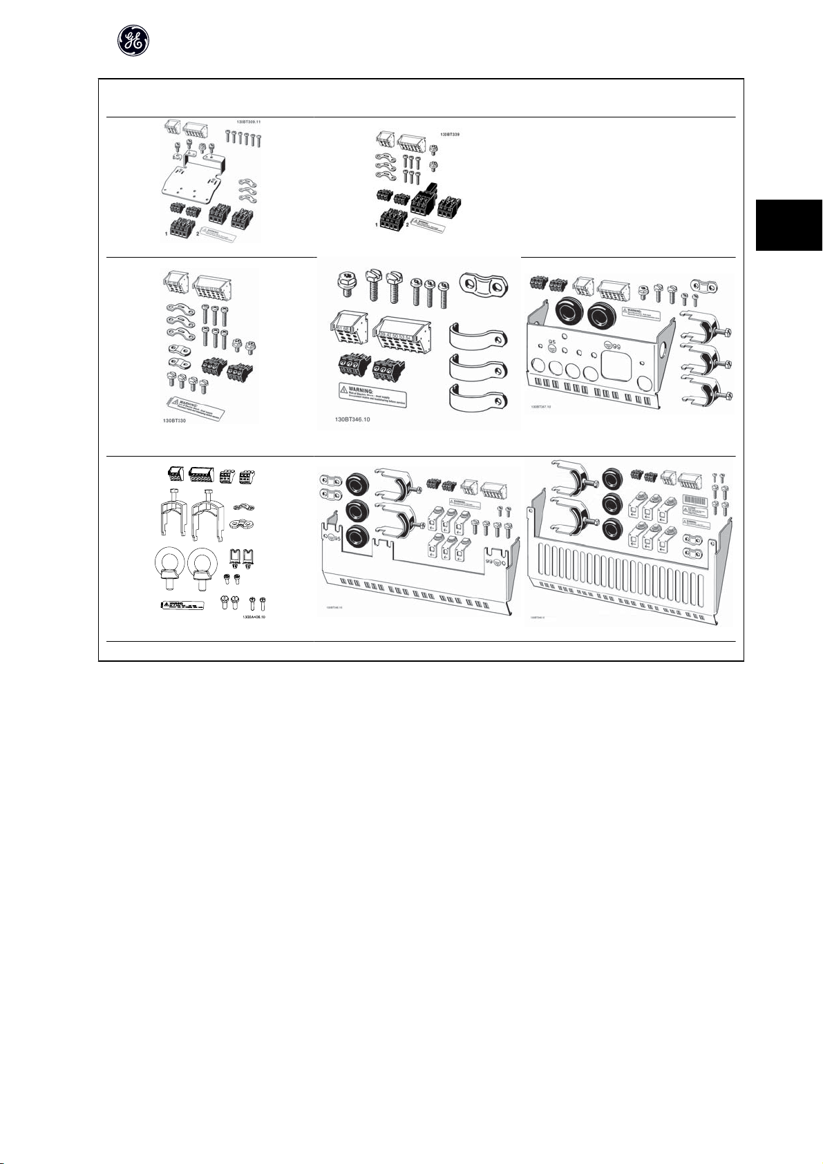
Accessory Bags: Find the following parts included in the frequency converter accessory bags
Unit Sizes 22 and 23, IP20 Open Chassis Unit Size 15, Nema 12 or Nema 4
AF-650 GP Operating Instructions
3
Unit Sizes 21 and 22
IP55/Type 12
Unit Sizes 31 and 32, IP55/Nema 12, IP66/Nema 4 Unit Size 23, IP20 Open Chassis Unit Size 24, IP20 Open Chassis
1 + 2 only available in units with brake chopper. For DC link connection (Load sharing) the connector 1 can be ordered separately
Unit Size 23, IP20 Open Chassis Unit Size 24, IP20 Open Chassis
13
Page 15
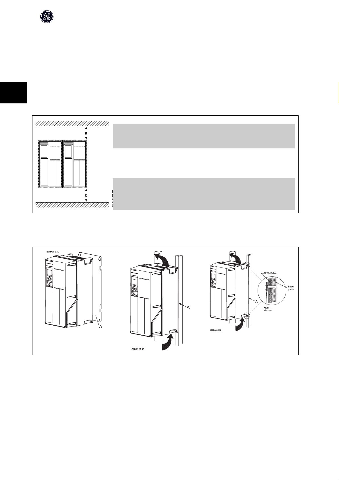
3.2 Mechanical Installation
3.2.1 Mechanical mounting
All IP20 .
If the P21/Nema 1 field installed option kits are installed, there must be a clearance of a minimum of 50mm or 2 inches between drives.
3
For optimal cooling conditions allow a free air passage above and below the frequency converter. See table below.
Air passage for different Unit Sizes
AF-650 GP Operating Instructions
Unit
Size:
a (mm): 100 100 100 200 200 200 200 200 225 200 225
b (mm): 100 100 100 200 200 200 200 200 225 200 225
Table 3.1:
1. Drill holes in accordance with the measurements given.
2. You must provide screws suitable for the surface on which you want to mount the frequency converter. Retighten all four screws.
12 13 15 21 22 23 24 31 32 33 34
Table 3.2: Mounting Unit Sizes 15, 21, 22, 23, 24, 31, 32, 33 and 34 on a non-solid back wall, the drive must be provided with a back plate A due to insufficient
cooling air over the heat sink.
14
Page 16

AF-650 GP Operating Instructions
3.2.2 Panel Through Mounting
A Panel Through Mount Kit is available for frequency converter series AF-600 FP, .
In order to increase heatsink cooling and reduce panel depth, the frequency converter may be mounted in a through panel. Furthermore the in-built fan can then
be removed.
The kit is available for Unit Sizes 15 through 32 (230V, 1/3 to 50HP and 460V/575V 1/2 to 100HP) .
NB!
This kit cannot be used with cast front covers. No cover or imminent plastic cover must be used instead.
For more information please contact GE.
3
15
Page 17

AF-650 GP Operating Instructions
3.3 Electrical Installation
NB!
Cables General
All cabling must comply with national and local regulations on cable cross-sections and ambient temperature. Copper (60/75°C) conductors are recommended.
Aluminium Conductors
3
Terminals can accept aluminium conductors but the conductor surface has to be clean and the oxidation must be removed and sealed by neutral acid-free
Vaseline grease before the conductor is connected.
Furthermore the terminal screw must be retightened after two days due to softness of the aluminium. It is crucial to keep the connection a gas tight joint, otherwise
the aluminium surface will oxidize again.
Tightening-up Torque
Unit Size 200 - 240 V 380 - 500 V 525 - 690 V Cable for: Tightening up torque
11 0.25-1.5 kW 0.37-1.5 kW - Mains, Brake resistor, load sharing, Motor ca12 0.25-2.2 kW 0.37-4 kW 0.75-4 kW
13 3-3.7 kW 5.5-7.5 kW 5.5-7.5 kW
15 3-3.7 kW 5.5-7.5 kW 0.75-7.5 kW
21 5.5-7.5 kW 11-15 kW - Mains, Brake resistor, load sharing, Motor ca-
22 11 kW 18.5-22 kW - Mains, Brake resistor, load sharing cables 4.5 Nm
23 5.5-7.5 kW 11-15 kW - Mains, Brake resistor, load sharing, Motor ca-
24 11-15 kW 18.5-30 kW - Mains, Brake resistor, load sharing, Motor ca-
31 15-22 kW 30-45 kW - Mains, Brake resistor, load sharing cables 10 Nm
32 30-37 kW 55-75 kW - Mains, motor cables
33 18.5-22 kW 30-37 kW - Mains, Brake resistor, load sharing, Motor ca-
34 37-45 kW 55-75 kW - Mains, motor cables
bles
bles
Relay 0.5-0.6 Nm
Earth 2-3 Nm
Motor cables 4.5 Nm
Relay 0.5-0.6 Nm
Earth 2-3 Nm
bles
Relay 0.5-0.6 Nm
Earth 2-3 Nm
bles
Relay 0.5-0.6 Nm
Earth 2-3 Nm
Motor cables 10 Nm
Relay 0.5-0.6 Nm
Earth 2-3 Nm
Load Sharing, brake cables 14 Nm
Relay 0.5-0.6 Nm
Earth 2-3 Nm
bles
Relay 0.5-0.6 Nm
Earth 2-3 Nm
Load Sharing, brake cables 14 Nm
Relay 0.5-0.6 Nm
Earth 2-3 Nm
0.5-0.6 Nm
1.8 Nm
1.8 Nm
4.5 Nm
14 Nm (up to 95 mm2)
24 Nm (over 95 mm
10 Nm
14 Nm (up to 95 mm2)
24 Nm (over 95 mm
2
)
2
)
3.3.1 Removal of Knockouts for Extra Cables
1. Remove cable entry from the frequency converter (Avoiding foreign parts falling into the frequency converter when removing knockouts)
2. Cable entry has to be supported around the knockout you intend to remove.
3. The knockout can now be removed with a strong mandrel and a hammer.
4. Remove burrs from the hole.
5. Mount Cable entry on frequency converter.
16
Page 18

AF-650 GP Operating Instructions
3.3.2 Connection to Mains and Earthing
NB!
The plug connector for power is plugable on frequency converters up to 7.5 kW.
1. Fit the two screws in the de-coupling plate, slide it into place and tighten the screws.
2. Make sure the frequency converter is properly earthed. Connect to earth connection (terminal 95). Use screw from the accessory bag.
3. Place plug connector 91(L1), 92(L2), 93(L3) from the accessory bag onto the terminals labelled MAINS at the bottom of the frequency converter.
4. Attach mains wires to the mains plug connector.
5. Support the cable with the supporting enclosed brackets.
NB!
Check that mains voltage corresponds to the mains voltage of the name plate.
IT Mains
Do not connect 400 V frequency converters with RFI-filters to mains supplies with a voltage between phase and earth of more than 440 V.
3
The earth connection cable cross section must be at least 10 mm2 or 2 x rated mains wires terminated separately according to EN 50178.
The mains connection is fitted to the mains switch if this is included.
Mains connection for Unit Sizes 12 and 13 IP20 Open Chassis drive types
(230V to 5HP, 460V/575V to 10HP):
17
Page 19

Mains connector (IP 55/66)Unit Size 15 Nema 12 or Nema 4 drive types
(230V to 5HP, 460V/575V to 10HP)
3
AF-650 GP Operating Instructions
Illustration 3.2: Mains connection for unit sizes 21 and 22 Nema 12 or Nema
4 drive types (230V, 7.5 to 15HP, 460V/575V, 15 to 30HP).
Illustration 3.4: Mains connection for unit size 24 IP20 Open Chassis drive
type (230V, 15 to 20HP, 460V/575V, 25 to 40HP).
Illustration 3.3: Mains connection for unit size 23 IP20 Open Chassis drive
type (230V, 7.5 to 10HP, 460V/575V, 15 to 25HP).
Illustration 3.5: Mains connection for unit sizes 31 and 32 Nema 12 or Nema
4 drive types (230V, 20 to 50HP, 460V, 40 to 100HP, 575V, 40 to 125HP).
18
Page 20

AF-650 GP Operating Instructions
3
Illustration 3.6: Mains connection for unit size 33 IP20 Open Chassis drive
type (230V, 25 to 30HP, 460V/575V, 50 to 60HP).
Illustration 3.7: Mains connection for unit size 34 IP20 Open Chassis drive
type (230V, 40 to 50HP, 460V, 75 to 100HP, 575V, 75 to 125HP).
3.3.3 Motor Connection
NB!
Use a screened/armoured motor cable to comply with EMC emission specifications. For more information, see EMC Test Results.
See section General Specifications for correct dimensioning of motor cable cross-section and length.
Screening of cables: Avoid installation with twisted screen ends (pigtails). If it is necessary to break the screen to install a motor isolator or motor contactor, the
screen must be continued at the lowest possible HF impedance.
Connect the motor cable screen to both the decoupling plate of the frequency converter and to the metal housing of the motor.
Make the screen connections with the largest possible surface area (cable clamp). This is done by using the supplied installation devices in the frequency converter.
If it is necessary to split the screen to install a motor isolator or motor relay, the screen must be continued with the lowest possible HF impedance.
Cable-length and cross-section: The frequency converter has been tested with a given length of cable and a given cross-section of that cable. If the cross-section
is increased, the cable capacitance - and thus the leakage current - may increase, and the cable length must be reduced correspondingly. Keep the motor cable
as short as possible to reduce the noise level and leakage currents.
Switching frequency: When frequency converters are used together with Sine-wave filters to reduce the acoustic noise from a motor, the switching frequency
must be set according to the Sine-wave filter instruction in par. F-26 Motor Noise (Carrier Freq).
1. Fasten decoupling plate to the bottom of the frequency converter with screws and washers from the accessory bag.
2. Attach motor cable to terminals 96 (U), 97 (V), 98 (W).
3. Connect to earth connection (terminal 99) on decoupling plate with screws from the accessory bag.
4. Insert plug connectors 96 (U), 97 (V), 98 (W) (up to 7.5 kW) and motor cable to terminals labelled MOTOR.
5. Fasten screened cable to decoupling plate with screws and washers from the accessory bag.
All types of three-phase asynchronous standard motors can be connected to the frequency converter. Normally, small motors are star-connected (230/400 V, Y).
Large motors are normally delta-connected (400/690 V, Δ). Refer to the motor name plate for correct connection mode and voltage.
19
Page 21

3
Illustration 3.8: Motor connection for units sizes 12 and 13 IP20 Open Chassis
drive types (230V to 5HP, 460V/575V to 10HP)
AF-650 GP Operating Instructions
Illustration 3.9: Motor connection for unit size 15 Nema 12 or Nema 4 drive
types (230V to 5HP, 460V/575V to 10HP)
Illustration 3.10: Motor connection for unit sizes 21 and 22 Nema 12 or Nema
4 drive types (230V, 7.5 to 15HP, 460V/575V, 15 to 30HP)
Illustration 3.12: Motor connection for for unit size 24 IP20 Open Chassis
drive type (230V, 15 to 20HP, 460V/575V, 25 to 40HP).
Illustration 3.11: Motor connection for for unit size 23 IP20 Open Chassis
drive type (230V, 7.5 to 10HP, 460V/575V, 15 to 25HP).
20
Page 22

Illustration 3.13: Motor connection for unit sizes 31 and 32 Nema 12 or Nema
4 drive types (230V, 20 to 50HP, 460V, 40 to 100HP, 575V, 40 to 125HP)
AF-650 GP Operating Instructions
3
Illustration 3.14: Motor connection for unit sizes 33 and 34 IP20 Open Chas-
sis drive types (230V, 25 to 50HP, 460V, 50 to 100HP, 575V, 50 to 125HP).
Illustration 3.15: Cable entry holes for unit size 21. The suggested use of the
holes are purely recommendations and other solutions are possible.
Illustration 3.16: Cable entry holes for unit size 22. The suggested use of the
holes are purely recommendations and other solutions are possible.
Term. no.
U1 V1 W1
U1 V1 W1
1)
Protected Earth Connection
96 97 98 99
U V W
W2 U2 V2 6 wires out of motor
1)
Motor voltage 0-100% of mains voltage.
PE
Delta-connected
1)
PE
1)
Star-connected U2, V2, W2
PE
Illustration 3.17: Cable entry holes for unit size 31. The suggested use of the
holes are purely recommendations and other solutions are possible.
Illustration 3.18: Cable entry holes for unit size 32. The suggested use of the
holes are purely recommendations and other solutions are possible.
3 wires out of motor
U2, V2 and W2 to be interconnected separately.
21
Page 23

AF-650 GP Operating Instructions
3
3.3.4 Fuses
Branch circuit protection:
In order to protect the installation against electrical and fire hazard, all branch circuits in an installation, switch gear, machines etc., must be short-circuited and
overcurrent protected according to national/international regulations.
Short-circuit protection:
The frequency converter must be protected against short-circuit to avoid electrical or fire hazard. GE recommends using the fuses mentioned below to protect
service personnel and equipment in case of an internal failure in the drive. The frequency converter provides full short-circuit protection in case of a short-circuit
on the motor output.
Overcurrent protection:
Provide overload protection to avoid fire hazard due to overheating of the cables in the installation. Fuses or circuit breakers can be used to provide the overcurrent
protection in the installation. Overcurrent protection must always be carried out according to national regulations.
The AF-650 GP drive is suitable in a circuit capable of supplying a maximum of 100,000 A
Non UL compliance
If UL/cUL is not to be complied with, we recommend using the following fuses, which will ensure compliance with EN50178:
In case of malfunction, not following the recommendation may result in unnecessary damage to the frequency converter.
AF-650 GP
1/3 to 1 HP 10A 200-240 V type gG
2 to 3 HP 20A 200-240 V type gG
5 HP 32A 200-240 V type gG
7.5 to 10 HP 63A 380-500 V type gG
15 HP 80A 380-500 V type gG
20 to 25 HP 125A 380-500 V type gG
30 HP 160A 380-500 V type aR
40 HP 200A 380-500 V type aR
50 HP 250A 380-500 V type aR
1) Max. fuses - refer to national/international regulations to select an appropriate fuse size.
AF-650 GP
3 to 5 HP 10A 380-500 V type gG
3 to 5 HP 20A 380-500 V type gG
7.5 to 10 HP 32A 380-500 V type gG
15 to 25 HP 63A 380-500 V type gG
30 HP 80A 380-500 V type gG
40 HP 100A 380-500 V type gG
50 HP 125A 380-500 V type gG
60 HP 160A 380-500 V type aR
75 to 100 HP 250A 380-500 V type aR
Max. fuse size
Max. fuse size
1)
1)
(symmetrical), 500 V maximum.
rms
Voltage Type
Voltage Type
22
Page 24

UL Compliance
200-240 V
AF-650 GP Operating Instructions
AF-650 GP
HP Type RK1 Type J Type T Type CC Type CC Type CC
1/3 to 1/2 HP KTN-R05 JKS-05 JJN-06 FNQ-R-5 KTK-R-5 LP-CC-5
1 HP KTN-R10 JKS-10 JJN-10 FNQ-R-10 KTK-R-10 LP-CC-10
2 HP KTN-R15 JKS-15 JJN-15 FNQ-R-15 KTK-R-15 LP-CC-15
3 HP KTN-R20 JKS-20 JJN-20 FNQ-R-20 KTK-R-20 LP-CC-20
5 HP KTN-R30 JKS-30 JJN-30 FNQ-R-30 KTK-R-30 LP-CC-30
7.5 HP KTN-R50 KS-50 JJN-50 - - 10 HP KTN-R60 JKS-60 JJN-60 - - 15 HP KTN-R80 JKS-80 JJN-80 - - 20 to 25 HP KTN-R125 JKS-150 JJN-125 - - -
AF-650 GP SIBA Littel fuse
HP Type RK1 Type RK1 Type CC Type RK1
1/3 to 1/2 HP 5017906-005 KLN-R05 ATM-R05 A2K-05R
1 HP 5017906-010 KLN-R10 ATM-R10 A2K-10R
2 HP 5017906-016 KLN-R15 ATM-R15 A2K-15R
3 HP 5017906-020 KLN-R20 ATM-R20 A2K-20R
5 HP 5012406-032 KLN-R30 ATM-R30 A2K-30R
7.5 HP 5014006-050 KLN-R50 - A2K-50R
10 HP 5014006-063 KLN-R60 - A2K-60R
15 HP 5014006-080 KLN-R80 - A2K-80R
20 to 25 HP 2028220-125 KLN-R125 - A2K-125R
AF-650 GP Bussmann SIBA Littel fuse
HP Type JFHR2 Type RK1 JFHR2 JFHR2
30 HP FWX-150 2028220-150 L25S-150 A25X-150
40 HP FWX-200 2028220-200 L25S-200 A25X-200
50 HP FWX-250 2028220-250 L25S-250 A25X-250
Bussmann Bussmann Bussmann Bussmann Bussmann Bussmann
Ferraz-
Shawmut
Ferraz-
Shawmut
Ferraz-
Shawmut
3
KTS-fuses from Bussmann may substitute KTN for 240 V frequency converters.
FWH-fuses from Bussmann may substitute FWX for 240 V frequency converters.
KLSR fuses from LITTEL FUSE may substitute KLNR fuses for 240 V frequency converters.
L50S fuses from LITTEL FUSE may substitute L50S fuses for 240 V frequency converters.
A6KR fuses from FERRAZ SHAWMUT may substitute A2KR for 240 V frequency converters.
A50X fuses from FERRAZ SHAWMUT may substitute A25X for 240 V frequency converters.
380-500 V
AF-650 GP
HP Type RK1 Type J Type T Type CC Type CC Type CC
1/2 to 1 HP KTS-R6 JKS-6 JJS-6 FNQ-R-6 KTK-R-6 LP-CC-6
2 to 3 HP KTS-R10 JKS-10 JJS-10 FNQ-R-10 KTK-R-10 LP-CC-10
5 HP KTS-R20 JKS-20 JJS-20 FNQ-R-20 KTK-R-20 LP-CC-20
7.5 HP KTS-R25 JKS-25 JJS-25 FNQ-R-25 KTK-R-25 LP-CC-25
10 HP KTS-R30 JKS-30 JJS-30 FNQ-R-30 KTK-R-30 LP-CC-30
15 HP KTS-R40 JKS-40 JJS-40 - - 20 HP KTS-R50 JKS-50 JJS-50 - - 25 HP KTS-R60 JKS-60 JJS-60 - - 30 HP KTS-R80 JKS-80 JJS-80 - - 40 HP KTS-R100 JKS-100 JJS-100 - - 50 HP KTS-R125 JKS-150 JJS-150 - - 60 HP KTS-R150 JKS-150 JJS-150 - - -
Bussmann Bussmann Bussmann Bussmann Bussmann Bussmann
23
Page 25

AF-650 GP Operating Instructions
3
AF-650 GP SIBA Littel fuse
HP Type RK1 Type RK1 Type CC Type RK1
1/2 to 1 HP 5017906-006 KLS-R6 ATM-R6 A6K-6R
2 to 3 HP 5017906-010 KLS-R10 ATM-R10 A6K-10R
5 HP 5017906-020 KLS-R20 ATM-R20 A6K-20R
7.5 HP 5017906-025 KLS-R25 ATM-R25 A6K-25R
10 HP 5012406-032 KLS-R30 ATM-R30 A6K-30R
15 HP 5014006-040 KLS-R40 - A6K-40R
20 HP 5014006-050 KLS-R50 - A6K-50R
25 HP 5014006-063 KLS-R60 - A6K-60R
30 HP 2028220-100 KLS-R80 - A6K-80R
40 HP 2028220-125 KLS-R100 - A6K-100R
50 HP 2028220-125 KLS-R125 - A6K-125R
60 HP 2028220-160 KLS-R150 - A6K-150R
AF-650 GP Bussmann Bussmann Bussmann Bussmann
HP JFHR2 Type H Type T JFHR2
75 HP FWH-200 - - 100 HP FWH-250 - - -
AF-650 GP SIBA Littel fuse
HP Type RK1 JFHR2 JFHR2 JFHR2
75 HP 2028220-200 L50S-225 - A50-P225
100 HP 2028220-250 L50S-250 A50-P250
Ferraz-Shawmut A50QS fuses may be substituted for A50P fuses.
170M fuses shown from Bussmann use the -/80 visual indicator. –TN/80 Type T, -/110 or TN/110 Type T indicator fuses of the same size and amperage
may be substituted.
550 - 600V
AF-650 GP
HP Type RK1 Type J Type T Type CC Type CC Type CC
1 to 2 HP KTS-R-5 JKS-5 JJS-6 FNQ-R-5 KTK-R-5 LP-CC-5
3 to 5 HP KTS-R10 JKS-10 JJS-10 FNQ-R-10 KTK-R-10 LP-CC-10
7.5 to 10 HP KTS-R20 JKS-20 JJS-20 FNQ-R-20 KTK-R-20 LP-CC-20
Bussmann Bussmann Bussmann Bussmann Bussmann Bussmann
Ferraz-
Shawmut
Ferraz-
Shawmut
Ferraz-
Shawmut
Ferraz-
Shawmut
AF-650 GP SIBA Littel fuse
HP Type RK1 Type RK1 Type RK1
1 to 2 HP 5017906-005 KLSR005 A6K-5R
3 to 5 HP 5017906-010 KLSR010 A6K-10R
7.5 to 10 HP 5017906-020 KLSR020 A6K-20R
AF-650 GP Bussmann SIBA
HP JFHR2 Type RK1 Type RK1
50 HP 170M3013 2061032.125 6.6URD30D08A0125
60 HP 170M3014 2061032.160 6.6URD30D08A0160
75 HP 170M3015 2061032.200 6.6URD30D08A0200
100 HP 170M3015 2061032.200 6.6URD30D08A0200
170M fuses shown from Bussmann use the -/80 visual indicator. –TN/80 Type T, -/110 or TN/110 Type T indicator fuses of the same size and amperage
may be substituted.
Ferraz-
Shawmut
Ferraz-
Shawmut
24
Page 26

3.3.5 Access to Control Terminals
All terminals to the control cables are located underneath the terminal cover
on the front the IP20 Open Chassis and IP20 with Nema 1 field installed kits..
Remove the terminal cover with a screwdriver.
Remove front-cover of Nema 12 and Nema 4 drive types to access control
terminals. When replacing the front-cover, please ensure proper fastening by
applying a torque of 2 Nm.
AF-650 GP Operating Instructions
3
130BT248
Illustration 3.19: Access to control terminals for unit sizes 12, 13, 23, 24, 33,
and 34
130BT334.11
Illustration 3.20: Access to control terminals for unit sizes 15, 21, 22, 31, and
32
25
Page 27

3.3.6 Electrical Installation, Control Terminals
To mount the cable to the terminal:
1. Strip insulation of 9-10 mm
1)
in the square hole.
1)
in the square hole.
1.
3
2.
Insert a screwdriver
3. Insert the cable in the adjacent circular hole.
4. Remove the screw driver. The cable is now mounted to the terminal.
To remove the cable from the terminal:
1.
Insert a screwdriver
2. Pull out the cable.
1)
Max. 0.4 x 2.5 mm
AF-650 GP Operating Instructions
2.
3.
26
Page 28

3.4 Connection Examples
3.4.1 Start/Stop
Terminal 18 = par. E-01 Terminal 18 Digital Input [8] Start
Terminal 27 = par. E-03 Terminal 27 Digital Input [0] No operation (Default
coast inverse)
Terminal 37 = Safe stop
AF-650 GP Operating Instructions
3
3.4.2 Pulse Start/Stop
Terminal 18 = par. E-01 Terminal 18 Digital InputLatched start, [9]
Terminal 27= par. E-03 Terminal 27 Digital InputStop inverse, [6]
Terminal 37 = Safe stop
27
Page 29

3.4.3 Speed Up/Down
Terminals 29/32 = Speed up/down:.
Terminal 18 = par. E-01 Terminal 18 Digital Input Start [9] (default)
Terminal 27 = par. E-03 Terminal 27 Digital Input Freeze reference
[19]
Terminal 29 = par. E-04 Terminal 29 Digital Input Speed up [21]
Terminal 32 = par. E-05 Terminal 32 Digital Input Speed down [22]
3
3.4.4 Potentiometer Reference
Voltage reference via a potentiometer:
Reference Source 1 = [1] Analog input 53 (default)
Terminal 53, Low Voltage = 0 Volt
Terminal 53, High Voltage = 10 Volt
Terminal 53, Low Ref./Feedback = 0 RPM
Terminal 53, High Ref./Feedback = 1500 RPM
Switch S201 = OFF (U)
AF-650 GP Operating Instructions
28
Page 30

3.5.1 Electrical Installation, Control Cables
AF-650 GP Operating Instructions
3
Illustration 3.21: Diagram showing all electrical terminals without options.
Terminal 37 is the input to be used for Safe Stop. For instructions on Safe Stop installation please refer to the section Safe Stop Installation of the AF-650 GP
Design Guide.
Very long control cables and analogue signals may in rare cases and depending on installation result in 50/60 Hz earth loops due to noise from mains supply
cables.
If this occurs, it may be necessary to break the screen or insert a 100 nF capacitor between screen and chassis.
The digital and analogue inputs and outputs must be connected separately to the common inputs (terminal 20, 55, 39) of the frequency converter to avoid ground
currents from both groups to affect other groups. For example, switching on the digital input may disturb the analog input signal.
29
Page 31

Input polarity of control terminals
3
NB!
Control cables must be screened/armoured.
AF-650 GP Operating Instructions
See section entitled Earthing of Screened/Armoured Control Cables for the
correct termination of control cables.
130BA681.10
130BA681.10
30
Page 32

AF-650 GP Operating Instructions
3.5.2 Switches S201, S202, and S801
Switches S201 (A53) and S202 (A54) are used to select a current (0-20 mA) or a voltage (-10 to 10 V) configuration of the analog input terminals 53 and 54 respectively.
Switch S801 (BUS TER.) can be used to enable termination on the RS-485 port (terminals 68 and 69).
See drawing Diagram showing all electrical terminals in section Electrical Installation.
Default setting:
S201 (A53) = OFF (voltage input)
S202 (A54) = OFF (voltage input)
S801 (Bus termination) = OFF
When changing the function of S201, S202 or S801 be careful not to use force for the switch over. It is recommended to remove the Keypad
fixture (cradle) when operating the switches. The switches must not be operated with power on the frequency converter.
3
130BT310.10
31
Page 33

3.6.1 Final Set-Up and Test
To test the set-up and ensure that the frequency converter is running, follow these steps.
Step 1. Locate the motor name plate
NB!
The motor is either star- (Y) or delta- connected (). This information is located on the motor name plate data.
3
AF-650 GP Operating Instructions
Step 2. Enter the motor name plate data in this parameter list.
To access this list first press the [QUICK MENU] key then select “Quick Setup”.
Use the up and down arrow keys to navigate to the parameters associated
with the motor nameplate values.
Step 3. Activate the Auto Tune
Performing an Auto Tune will ensure optimum performance. The Auto Tune measures the values from the motor model equivalent diagram.
1. Connect terminal 37 to terminal 12 (if terminal 37 is available).
2. Connect terminal 27 to terminal 12 or set par. E-03 Terminal 27 Digital Input to 'No function'.
3. Activate the Auto Tune par. P-04 Auto Tune.
4. Choose between complete or reduced Auto Tune. If a Sine-wave filter is connected, run only the reduced Auto Tune, or remove the Sine-wave filter and
run complete Auto Tune..
5. Press the [OK] key. The display shows “Press [Hand] to start”.
6. Press the [Hand] key. A progress bar indicates if the Auto Tune is in progress.
Stop the Auto Tune during operation
1. Press the [OFF] key - the frequency converter enters into alarm mode and the display shows that the Auto Tune was terminated by the user.
Successful Auto Tune
1. The display shows “Press [OK] to finish Auto Tune”.
2. Press the [OK] key to exit the Auto Tune state.
1.
2. par. F-05 Motor Rated Voltage
3. par. F-04 Base Frequency
4. par. P-03 Motor Current
5. par. P-06 Base Speed
par. P-07 Motor Power [kW]
par. P-02 Motor Power [HP]
32
Page 34

AF-650 GP Operating Instructions
Unsuccessful Auto Tune
1. The frequency converter enters into alarm mode. A description of the alarm can be found in the Warnings and Alarms chapter.
2. "Report Value” in the [Alarm Log] shows the last measuring sequence carried out by the Auto Tune, before the frequency converter entered alarm mode.
This number along with the description of the alarm will assist you in troubleshooting. If you contact GE for service, make sure to mention number and
alarm description.
NB!
Unsuccessful Auto Tune is often caused by incorrectly entering motor name plate data or a too big difference between the motor power size and the frequency
converter power size.
Step 4. Set speed limit and accel/decel times
par. F-52 Minimum Reference
par. F-53 Maximum Reference
Table 3.3: Set up the desired limits for speed and ramp time.
par. F-18 Motor Speed Low Limit [RPM] or par. F-16 Motor Speed Low
Limit [Hz]
par. F-17 Motor Speed High Limit [RPM] or par. F-15 Motor Speed High
Limit [Hz]
par. F-07 Accel Time 1
par. F-08 Decel Time 1
3
33
Page 35

3.7 Additional Connections
3.7.1 Mechanical Brake Control
In hoisting/lowering applications, it is necessary to be able to control an electro-mechanical brake:
• Control the brake using any relay output or digital output (terminal 27 or 29).
• Keep the output closed (voltage-free) as long as the frequency converter is unable to ‘support’ the motor, for example due to the load being too heavy.
3
• Select Mechanical brake control [32] in E-2# for applications with an electro-mechanical brake.
• The brake is released when the motor current exceeds the preset value in par. B-20 Release Brake Current.
• The brake is engaged when the output frequency is less than the frequency set in par. B-21 Activate Brake Speed [RPM]or par. B-22 Activate Brake Speed
[Hz], and only if the frequency converter carries out a stop command.
If the frequency converter is in alarm mode or in an over-voltage situation, the mechanical brake immediately cuts in.
3.7.2 Parallel Connection of Motors
The frequency converter can control several parallel-connected motors. The
total current consumption of the motors must not exceed the rated output
current I
for the frequency converter.
M,N
AF-650 GP Operating Instructions
NB!
Installations with cables connected in a common joint as in the illustration
below, is only recommended for short cable lengths.
NB!
When motors are connected in parallel, par. P-04 Auto Tune cannot be used.
NB!
The electronic thermal overload of the frequency converter cannot be used
as motor protection for the individual motor in systems with parallel-con-
nected motors. Provide furthe r motor protection by e.g. thermistors in each
motor or individual thermal relays (circuit breakers are not suitable as pro-
tection).
Problems may arise at start and at low RPM values if motor sizes are widely different because small motors' relatively high ohmic resistance in the stator calls for
a higher voltage at start and at low RPM values.
3.7.3 Motor Thermal Protection
The electronic thermal overload in the frequency converter has received UL-approval for single motor protection, when par. F-10 Electronic Overloadis set for
Elec. OL Trip and par. P-03 Motor Current is set to the rated motor current (see motor name plate).
34
Page 36

3.7.4 How to Connect a PC to the frequency converter
To control the frequency converter from a PC, install the DCT-10 Drive Control Tool
Software.
The PC is connected via a standard (host/device) USB cable, or via the RS485
interface as shown in the section Bus Connection in the Programming Guide.
NB!
The USB connection is galvanically isolated from the supply voltage (PELV)
and other high-voltage terminals. The USB connection is connected to pro-
tection earth on the frequency converter. Use only isolated laptop as PC
connection to the USB connector on the frequency converter.
3.7.5 The DCT-10 Drive Control Tool Software
AF-650 GP Operating Instructions
3
Illustration 3.22: USB connection.
Data storage in PC via DCT-10 Drive Control Tool Software:
1. Connect a PC to the unit via USB com port
2. Open DCT-10 Drive Control Tool Software
3. Select in the “network” section the USB port
4. Choose “Copy”
5. Select the “project” section
6. Choose “Paste”
7. Choose “Save as”
All parameters are now stored.
Data transfer from PC to drive via DCT-10 Drive Control Tool Software:
1. Connect a PC to the unit via USB com port
2. Open DCT-10 Drive Control Tool Software
3. Choose “Open”– stored files will be shown
4. Open the appropriate file
5. Choose “Write to drive”
All parameters are now transferred to the drive.
A separate manual for DCT-10 Drive Control Tool Software as part of the software.
35
Page 37

4
AF-650 GP Operating Instructions
36
Page 38

4 How to Program
4.1 The Graphical Keypad
The easiest programming of the frequency converter is performed by the Graphical Keypad.
4.1.1 How to Program on the Graphical Keypad
The following instructions are valid for the graphical Keypad:
The keypad is divided into four functional groups:
1. Graphical display with Status lines.
2. Menu keys and indicator lights - changing parameters and switch-
ing between display functions.
3. Navigation keys and indicator lights (LEDs).
4. Operation keys and indicator lights (LEDs).
All data is displayed in the display, which can show up to five items of oper-
ating data while displaying [Status].
AF-650 GP Operating Instructions
4
Display lines:
a. Status line: Status messages displaying icons and graphic.
b. Line 1-2: Operator data lines displaying data defined or chosen by
the user. By pressing the [Status] key, up to one extra line can be
added.
c. Status line: Status messages displaying text.
37
Page 39

AF-650 GP Operating Instructions
4.1.2 Initial Commissioning
The easiest way of carrying out the initial commissioning is by using the Quick Menu button and follow the quick set-up procedure using Keypad (read table from
left to right). The example applies to open loop applications:
Press
Q2 Quick Set-Up
par. K-01 Language Set language
4
par. K-02 Motor Speed Unit Set motor speed in Hz or RPM
par. P-02 Motor Power [HP] or par. P-07 Motor
Power [kW]
par. F-05 Motor Rated Voltage Set Nameplate voltage
par. F-04 Base Frequency
par. P-03 Motor Current Set Nameplate current
par. P-06 Base Speed
par. F-01 Frequency Setting 1 Set reference source
par. F-02 Operation Method
par. F-07 Accel Time 1
par. F-08 Decel Time 1
par. F-10 Electronic Overload Set motor thermal protection
par. F-15 Motor Speed High Limit [Hz] or par.
F-17 Motor Speed High Limit [RPM]
par. F-16 Motor Speed Low Limit [Hz] or par.
F-18 Motor Speed Low Limit [RPM]
Set Motor nameplate power
Set Nameplate frequency
Set Nameplate speed in RPM
Select which reference site to activate
Set the accel time with reference to synchronous motor speed, n
Set the decel time time with reference to synchronous motor speed,
n
s
Set motor speed high limit in Hz or RPM
Set motor speed low limit in Hz or RPM
s
par. H-08 Reverse Lock
par. P-04 Auto Tune
38
Set allowed rotation direction
Set desired auto tune function. Enable complete auto tune is recommended
Page 40

4.2 Quick Setup Parameter List
K-01 Language
Option: Function:
Defines the language to be used in the display.
The frequency converter is delivered with 4 different languages.
[0] * English Part of Language packages 1 - 4
K-02 Motor Speed Unit
Option: Function:
This parameter cannot be adjusted while the motor is running.
The display showing depends on settings in par. K-02 Motor Speed Unit and par. K-03 Regional Settings.
The default setting of par. K-02 Motor Speed Unit and par. K-03 Regional Settings depends on which region
of the world the frequency converter is supplied to, but can be re-programmed as required.
NB!
Changing the Motor Speed Unit will reset certain parameters to their initial value. It is recommended to
select the motor speed unit first, before modifying other parameters.
AF-650 GP Operating Instructions
4
[0] RPM Selects display of motor speed variables and parameters (i.e. references, feedbacks and limits) in terms
of motor speed (RPM).
[1] * Hz Selects display of motor speed variables and parameters (i.e. references, feedbacks and limits) in terms
of output frequency to the motor (Hz).
P-02 Motor Power [HP]
Range: Function:
4.00 hp* [0.09 - 3000.00 hp] Enter the nominal motor power in HP according to the motor nameplate data. The default value corre-
sponds to the nominal rated output of the unit. This parameter is visible in Keypad if par. K-03 Region-
al Settings is US [1]
P-07 Motor Power [kW]
Range: Function:
4.00 kW* [0.09 - 3000.00 kW] Enter the nominal motor power in kW according to the motor nameplate data. The default value corre-
sponds to the nominal rated output of the unit.
This parameter cannot be adjusted while the motor is running. This parameter is visible in Keypad if par.
K-03 Regional Settings is International [0].
F-05 Motor Rated Voltage
Range: Function:
400. V* [10. - 1000. V] Enter the nominal motor voltage according to the motor nameplate data. The default value corresponds
to the nominal rated output of the unit.
This parameter cannot be adjusted while the motor is running.
F-04 Base Frequency
Range: Function:
50. Hz* [20 - 1000 Hz] Min - Max motor frequency: 20 - 1000 Hz.
Select the motor frequency value from the motor nameplate data. If a value different from 50 Hz or 60
Hz is selected, it is necessary to adapt the load independent settings in par. H-50 Motor Magnetisation at
Zero Speed to par. H-53 Model Shift Frequency. For 87 Hz operation with 230/400 V motors, set the name-
plate data for 230 V/50 Hz. Adapt par. F-17 Motor Speed High Limit [RPM] and par. F-53 Maxi-
mum Reference to the 87 Hz application.
39
Page 41

4
AF-650 GP Operating Instructions
P-03 Motor Current
Range: Function:
7.20 A* [0.10 - 10000.00 A] Enter the nominal motor current value from the motor nameplate data. This data is used for calculating
motor torque, motor thermal protection etc.
NB!
This parameter cannot be adjusted while the motor is running.
P-06 Base Speed
Range: Function:
1420. RPM* [100 - 60000 RPM] Enter the nominal motor speed value from the motor nameplate data. This data is used for calculating
automatic motor compensations.
NB!
This parameter cannot be changed while the motor is running.
F-01 Frequency Setting 1
Option: Function:
Select the reference input to be used for the first reference signal. par. F-01 Frequency Setting 1, par.
C-30 Frequency Command 2 and par. C-34 Frequency Command 3 define up to three different reference
signals. The sum of these reference signals defines the actual reference.
[0] No function
[1] * Analog Input 53
[2] Analog Input 54
[7] Frequency input 29
[8] Frequency input 33
[11] Local bus reference
[20] Digital Potentiometer
[21] Analog input X30-11 (OPCGPIO - General Purpose I/O Option Module)
[22] Analog input X30-12 (OPCGPIO - General Purpose I/O Option Module)
F-02 Operation Method
Option: Function:
Select which reference site to activate.
[0] * Linked to Hand / Auto Use local reference when in Hand mode; or remote reference when in Auto mode.
[1] Remote Use remote reference in both Hand mode and Auto mode.
[2] Local Use local reference in both Hand mode and Auto mode.
NB!
When set to Local [2], the frequency converter will start with this setting again following a 'power down'.
F-07 Accel Time 1
Range: Function:
3.00 s* [0.01 - 3600.00 s] Enter the accel time, i.e. the acceleration time from 0 RPM to the synchronous motor speed nS. Choose a
accel time such that the output current does not exceed the current limit in par. F-43 Current Limit during
ramping. The value 0.00 corresponds to 0.01 sec. in speed mode. See decel time in par. F-08 Decel Time
1.
40
Page 42

AF-650 GP Operating Instructions
t
s x
n
Par. F
− 07 =
acc
ref RPM
F-08 Decel Time 1
Range: Function:
3.00 s* [0.01 - 3600.00 s] Enter the decel time, i.e. the deceleration time from the synchronous motor speed ns to 0 RPM. Choose a
decel time such that no over-voltage arises in the inverter due to regenerative operation of the motor,
and such that the generated current does not exceed the current limit set in par. F-43 Current Limit. The
value 0.00 corresponds to 0.01 s in speed mode. See accel time in par. F-07 Accel Time 1.
t
s x
Par. F
− 08 =
dec
ref RPM
F-10 Electronic Overload
Option: Function:
The frequency converter determines the motor temperature for motor protection in two different ways:
• Via a thermistor sensor connected to one of the analog or digital inputs (par. F-12 Motor Ther-
mistor Input).
• Via calculation of the thermal load, based on the actual load and time. The calculated thermal
load is compared with the rated motor current I
calculations estimate the need for a lower load at lower speed due to less cooling from the fan
incorporated in the motor.
RPM
s
n
RPM
s
and the rated motor frequency f
M,N
. The
M,N
4
[0] * No protection Continuously overloaded motor, when no warning or trip of the frequency converter is required.
[1] Thermistor warning Activates a warning when the connected thermistor or KTY-sensor in the motor reacts in the event of
motor over-temperature.
[2] Thermistor trip Stops (trips) frequency converter when connected thermistor in motor reacts in the event of motor over-
temperature.
The thermistor cut-out value must be > 3 k.
Integrate a thermistor (PTC sensor) in the motor for winding protection.
[3] Electronic Overload Warning 1
[4] Electronic Overload Trip 1
[5] Electronic Overload Warning 2
[6] Electronic Overload Trip 2
[7] Electronic Overload Warning 3
[8] Electronic Overload Trip 3
[9] Electronic Overload Warning 4
[10] Electronic Overload Trip 4
41
Page 43

AF-650 GP Operating Instructions
Motor protection can be implemented using a range of techniques: PTC or KTY sensor (see also section KTY Sensor Connection) in motor windings; mechanical
thermal switch (Klixon type); or Electronic Thermal Overload.
Using a digital input and 24 V as power supply:
Example: The frequency converter trips when the motor temperature is too high
Parameter set-up:
Set par. F-10 Electronic Overload to Thermistor Trip [2]
Set par. F-12 Motor Thermistor Input to Digital Input [6]
4
Using a digital input and 10 V as power supply:
Example: The frequency converter trips when the motor temperature is too high.
Parameter set-up:
Set par. F-10 Electronic Overload to Thermistor Trip [2]
Set par. F-12 Motor Thermistor Input to Digital Input [6]
42
Page 44

Using an analog input and 10 V as power supply:
Example: The frequency converter trips when the motor temperature is too high.
Parameter set-up:
Set par. F-10 Electronic Overload to Thermistor Trip [2]
Set par. F-12 Motor Thermistor Input to Analog Input 54 [2]
AF-650 GP Operating Instructions
4
Input
Digital/analog
Digital 24 V < 6.6 k - > 10.8 k
Digital 10 V < 800 - > 2.7 k
Analog 10 V < 3.0 k - > 3.0 k
NB!
Check that the chosen supply voltage follows the specification of the used thermistor element.
Select Electronic Overload Warning 1-4, to activate a warning on the display when the motor is overloaded.
Select Electronic Overload Trip 1-4 to trip the frequency converter when the motor is overloaded.
Programme a warning signal via one of the digital outputs. The signal appears in the event of a warning and if the frequency converter trips (thermal warning).
Electronic Overload functions 1-4 will calculate the load when the set-up where they were selected is active. For example Electronic Overload 3 starts calculating
when setup 3 is selected. For the North American market: The Electronic Overload functions provide class 20 motor overload protection in accordance with NEC.
Supply Voltage
Volt
Threshold
Cut-out Values
F-15 Motor Speed High Limit (Hz)
Range: Function:
50/60.0 Hz* [par. H-12 - par. H-19 Hz] Enter the maximum limit for motor speed. The Motor Speed High Limit can be set to correspond to the
manufacturer’s recommended maximum of the motor shaft. The Motor Speed High Limit must exceed
the in par. F-16 Frequency Limiter (Low). Only par. F-18 Speed Limiter (Low) or par. F-16 Frequency Limiter
(Low) will be displayed depending on other parameters in the Main Menu and depending on default
settings dependant on global location.
NB!
Max. output frequency cannot exceed 10% of the inverter frequency (par. F-26 Motor Noise (Carrier Freq)).
43
Page 45

4
AF-650 GP Operating Instructions
F-16 Motor Speed Low Limit [Hz]
Range: Function:
0 Hz* [0.0 - par. H-14 Hz] Enter the minimum limit for motor speed. The Motor Speed Low Limit can be set to correspond to the
minimum output frequency of the motor shaft. The Motor Speed Low Limit must not exceed the setting
in par. F-15 Motor Speed High Limit (Hz).
F-17 Motor Speed High Limit [RPM]
Range: Function:
3600. RPM* [par. H-11 - 60000. RPM] Enter the maximum limit for motor speed. The Motor Speed High Limit can be set to correspond to the
manufacturer’s maximum rated motor speed. The Motor Speed High Limit must exceed the setting in
par. F-18 Motor Speed Low Limit [RPM].
NB!
Max. output frequency cannot exceed 10% of the inverter switching frequency (par. F-26 Motor Noise (Carrier Freq)).
F-18 Motor Speed Low Limit [RPM]
Range: Function:
0 RPM* [0 - par. H-13 RPM] Enter the minimum limit for motor speed. The Motor Speed Low Limit can be set to correspond to the
manufacturer’s recommended minimum motor speed. The Motor Speed Low Limit must not exceed the
setting in par. F-17 Motor Speed High Limit [RPM].
H-08 Reverse Lock
Option: Function:
Select the motor speed direction(s) required. Use this parameter to prevent unwanted reversing. When
par. H-40 Configuration Mode is set to Process [3], par. H-08 Reverse Lock is set to Clockwise [0] as default.
The setting in par. H-08 Reverse Lock does not limit options for setting par. F-15 Motor Speed High Limit
(Hz) or par. F-17 Motor Speed High Limit [RPM].
This parameter cannot be adjusted while the motor is running.
[0] * Clockwise
[1] Counter clockwise
[2] Both directions
P-04 Auto Tune
Option: Function:
The Auto Tune function optimises dynamic motor performance by au tomatically optimising the advanced
motor parameters (par. P-30 Stator Resistance (Rs) to par. P-35 Main Reactance (Xh)) at motor standstill.
Activate the Auto Tune function by pressing [Hand] after selecting [1] or [2]. See also the section Auto
Tuning in the AF-650 GP Design Guide. After a normal sequence, the display will read: "Press [OK] to finish
Auto Tune". After pressing the [OK] key the frequency converter is ready for operation.
This parameter cannot be adjusted while the motor is running.
[0] * Off
[1] Enable complete Auto Tune
[2] Enable reduced Auto Tune
Note:
• For the best results run Auto Tune on a cold motor.
• Auto Tune cannot be performed while the motor is running.
• Auto Tune cannot be performed on permanent magnet motors.
44
Page 46

AF-650 GP Operating Instructions
NB!
It is important to set motor par. F-04, F-05, and P-02 to P-08 correctly, since these form part of the Auto Tune algorithm. An Auto Tune should be performed to
achieve optimum dynamic motor performance. It may take up to 10 min, depending on the power rating of the motor.
NB!
Avoid generating external torque during Auto Tune.
NB!
If one of the settings in par. F-04, F-05, or P-02 to P-08 is changed, par. P-30 Stator Resistance (Rs) to par. P-01 Motor Poles, the advanced motor parameters,
will return to default setting.
NB!
Auto Tune will work problem-free on 1 motor size down, typically work on 2 motor sizes down, rarely work on 3 sizes down and never work on 4 sizes down.
Please keep in mind that the accuracy of the measured motor data will be poorer when you operate on motors smaller than nominal drive size.
4
45
Page 47

4.3 Parameter Lists
4
AF-650 GP Operating Instructions
46
Page 48

AF-650 GP Operating Instructions
Type
Conver-
sion index
tion
4
Par. No. # Parameter description Default value 4-set-up Change during opera-
4.3.1 K-## Keypad Set-up
K-0#
K-01 Language [0] English 1 set-up TRUE - Uint8
K-02 Motor Speed Unit [0] RPM 2 set-ups FALSE - Uint8
K-04 Operating State at Power-up [1] Forced stop, ref=old All set-ups TRUE - Uint8
K-10 Active Set-up [1] Set-up 1 1 set-up TRUE - Uint8
K-11 Edit Set-up [1] Set-up 1 All set-ups TRUE - Uint8
K-12 This Set-up Linked to [0] Not linked All set-ups FALSE - Uint8
K-14 Readout: Edit Set-ups / Channel 0 N/A All set-ups TRUE 0 Int32
K-20 Display Line 1.1 Small ExpressionLimit All set-ups TRUE - Uint16
K-21 Display Line 1.2 Small ExpressionLimit All set-ups TRUE - Uint16
K-22 Display Line 1.3 Small ExpressionLimit All set-ups TRUE - Uint16
K-24 Display Line 3 Large ExpressionLimit All set-ups TRUE - Uint16
K-3#
K-30 Unit for Custom Readout [0] None All set-ups TRUE - Uint8
K-31 Min Value of Custom Readout 0.00 CustomReadoutUnit All set-ups TRUE -2 Int32
K-4#
K-40 [Hand] Button on Keypad [1] Enabled All set-ups TRUE - Uint8
K-41 [Off] Button on Keypad [1] Enabled All set-ups TRUE - Uint8
K-43 [Reset] Button on Keypad [1] Enabled All set-ups TRUE - Uint8
K-50 Keypad Copy [0] No copy All set-ups FALSE - Uint8
K-51 Set-up Copy [0] No copy All set-ups FALSE - Uint8
K-6#
K-60 Main Menu Password 100 N/A 1 set-up TRUE 0 Int16
K-61 Access to Main Menu w/o Password [0] Full access 1 set-up TRUE - Uint8
K-03 Regional Settings [1] US 2 set-ups FALSE - Uint8
K-1#
K-13 Readout: Linked Set-ups 0 N/A All set-ups FALSE 0 Uint16
K-2#
K-23 Display Line 2 Large ExpressionLimit All set-ups TRUE - Uint16
K-25 Quick Start ExpressionLimit 1 set-up TRUE 0 Uint16
K-32 Max Value of Custom Readout 100.00 CustomReadoutUnit All set-ups TRUE -2 Int32
K-42 [Auto] Button on Keypad [1] Enabled All set-ups TRUE - Uint8
K-5#
K-66 Access to Quick Menu w/o Password [0] Full access 1 set-up TRUE - Uint8
K-65 Quick Menu Password 200 N/A 1 set-up TRUE 0 Int16
K-67 Bus Password Access 0 N/A All set-ups TRUE 0 Uint16
47
Page 49

AF-650 GP Operating Instructions
Type
Conver-
sion index
4
tion
Par. No. # Parameter description Default value 4-set-up Change during opera-
F-0#
F-01 Frequency Setting 1 null All set-ups TRUE - Uint8
F-02 Operation Method [0] Linked to Hand / Auto All set-ups TRUE - Uint8
F-04 Base Frequency ExpressionLimit All set-ups FALSE 0 Uint16
F-07 Accel Time 1 ExpressionLimit All set-ups TRUE -2 Uint32
F-09 Torque Boost 100 % All set-ups TRUE 0 Int16
F-10 Electronic Overload [0] No protection All set-ups TRUE - Uint8
F-08 Decel Time 1 ExpressionLimit All set-ups TRUE -2 Uint32
F-1#
F-05 Motor Rated Voltage ExpressionLimit All set-ups FALSE 0 Uint16
4.3.2 F-## Fundamental Parameters
F-03 Max Output Frequency 1 132.0 Hz All set-ups FALSE -1 Uint16
48
F-11 Motor External Fan [0] No All set-ups TRUE - Uint16
F-12 Motor Thermistor Input [0] None All set-ups TRUE - Uint8
F-16 Motor Speed Low Limit [Hz] ExpressionLimit All set-ups TRUE -1 Uint16
F-18 Motor Speed Low Limit [RPM] ExpressionLimit All set-ups TRUE 67 Uint16
F-22 Start Speed [RPM] ExpressionLimit All set-ups TRUE 67 Uint16
F-23 Start Speed [Hz] ExpressionLimit All set-ups TRUE -1 Uint16
F-24 Holding Time 0.0 s All set-ups TRUE -1 Uint8
F-26 Motor Noise (Carrier Freq) null All set-ups TRUE - Uint8
F-29 Start Current 0.00 A All set-ups TRUE -2 Uint32
F-37 Adv. Switching Pattern [1] SFAVM All set-ups TRUE - Uint8
F-38 Overmodulation [1] On All set-ups FALSE - Uint8
F-4#
F-40 Torque Limiter (Driving) ExpressionLimit All set-ups TRUE -1 Uint16
F-41 Torque Limiter (Braking) 100.0 % All set-ups TRUE -1 Uint16
F-5#
F-50 Reference Range null All set-ups TRUE - Uint8
F-51 Reference/Feedback Unit null All set-ups TRUE - Uint8
F-53 Maximum Reference ExpressionLimit All set-ups TRUE -3 Int32
F-6#
F-62 Catch up/slow Down Value 0.00 % All set-ups TRUE -2 Int16
F-64 Preset Relative Reference 0.00 % All set-ups TRUE -2 Int32
F-9#
F-90 Step Size 0.10 % All set-ups TRUE -2 Uint16
F-91 Accel/Decel Time 1.00 s All set-ups TRUE -2 Uint32
F-93 Maximum Limit 100 % All set-ups TRUE 0 Int16
F-15 Motor Speed High Limit [Hz] ExpressionLimit All set-ups TRUE -1 Uint16
F-17 Motor Speed High Limit [RPM] ExpressionLimit All set-ups TRUE 67 Uint16
F-2#
F-25 Start Function [2] Coast/delay time All set-ups TRUE - Uint8
F-3#
F-27 Motor Tone Random [0] Off All set-ups TRUE - Uint8
F-43 Current Limit ExpressionLimit All set-ups TRUE -1 Uint32
F-54 Reference Function [0] Sum All set-ups TRUE - Uint8
F-52 Minimum Reference 0 ReferenceFeedbackUnit All set-ups TRUE -3 Int32
F-68 Relative Scaling Reference Resource [0] No function All set-ups TRUE - Uint8
F-95 Accel/Decel Ramp Delay ExpressionLimit All set-ups TRUE -3 TimD
F-94 Minimum Limit -100 % All set-ups TRUE 0 Int16
F-92 Power Restore [0] Off All set-ups TRUE - Uint8
Page 50

AF-650 GP Operating Instructions
Type
Conver-
sion index
tion
4
Par. No. # Parameter description Default value 4-set-up Change during opera-
4.3.3 E-## Digital In/Outs
E-0#
E-00 Digital I/O Mode [0] PNP All set-ups FALSE - Uint8
E-01 Terminal 18 Digital Input null All set-ups TRUE - Uint8
E-03 Terminal 27 Digital Input null All set-ups TRUE - Uint8
E-05 Terminal 32 Digital Input [0] No operation All set-ups TRUE - Uint8
E-07 Terminal 37 Safe Stop [1] Safe Stop Alarm 1 set-up TRUE - Uint8
E-10 Accel Time 2 ExpressionLimit All set-ups TRUE -2 Uint32
E-11 Decel Time 2 ExpressionLimit All set-ups TRUE -2 Uint32
E-12 Accel Time 3 ExpressionLimit All set-ups TRUE -2 Uint32
E-14 Accel Time 4 ExpressionLimit All set-ups TRUE -2 Uint32
E-2#
E-20 Terminal 27 Digital Output null All set-ups TRUE - Uint8
E-21 Terminal 29 Digital Output null All set-ups TRUE - Uint8
E-26 On Delay, Relay 0.01 s All set-ups TRUE -2 Uint16
E-3#
E-30 Terminal X46/1 Digital Input [0] No operation All set-ups TRUE - Uint8
E-31 Terminal X46/3 Digital Input [0] No operation All set-ups TRUE - Uint8
E-33 Terminal X46/7 Digital Input [0] No operation All set-ups TRUE - Uint8
E-35 Terminal X46/11 Digital Input [0] No operation All set-ups TRUE - Uint8
E-5#
E-51 Terminal 27 Mode [0] Input All set-ups TRUE - Uint8
E-52 Terminal 29 Mode [0] Input All set-ups TRUE - Uint8
E-54 Terminal X30/3 Digital Input [0] No operation All set-ups TRUE - Uint8
E-56 Term X30/6 Digi Out (OPCGPIO) null All set-ups TRUE - Uint8
E-6#
E-60 Term. 29 Low Frequency 100 Hz All set-ups TRUE 0 Uint32
E-61 Term. 29 High Frequency 100 Hz All set-ups TRUE 0 Uint32
E-63 Term. 29 High Ref./Feedb. Value ExpressionLimit All set-ups TRUE -3 Int32
E-65 Term. 33 Low Frequency 100 Hz All set-ups TRUE 0 Uint32
E-67 Term. 33 Low Ref./Feedb. Value 0.000 ReferenceFeedbackUnit All set-ups TRUE -3 Int32
E-02 Terminal 19 Digital Input null All set-ups TRUE - Uint8
E-04 Terminal 29 Digital Input null All set-ups TRUE - Uint8
E-13 Decel Time 3 ExpressionLimit All set-ups TRUE -2 Uint32
E-06 Terminal 33 Digital Input [0] No operation All set-ups TRUE - Uint8
E-1#
E-15 Decel Time 4 ExpressionLimit All set-ups TRUE -2 Uint32
E-24 Function Relay null All set-ups TRUE - Uint8
E-27 Off Delay, Relay 0.01 s All set-ups TRUE -2 Uint16
E-32 Terminal X46/5 Digital Input [0] No operation All set-ups TRUE - Uint8
E-34 Terminal X46/9 Digital Input [0] No operation All set-ups TRUE - Uint8
E-36 Terminal X46/13 Digital Input [0] No operation All set-ups TRUE - Uint8
E-53 Terminal X30/2 Digital Input [0] No operation All set-ups TRUE - Uint8
E-55 Terminal X30/4 Digital Input [0] No operation All set-ups TRUE - Uint8
E-57 Term X30/7 Digi Out (OPCGPIO) null All set-ups TRUE - Uint8
E-64 Pulse Filter Time Constant #29 100 ms All set-ups FALSE -3 Uint16
E-62 Term. 29 Low Ref./Feedb. Value 0.000 ReferenceFeedbackUnit All set-ups TRUE -3 Int32
E-66 Term. 33 High Frequency 100 Hz All set-ups TRUE 0 Uint32
E-69 Pulse Filter Time Constant #33 100 ms All set-ups FALSE -3 Uint16
E-68 Term. 33 High Ref./Feedb. Value ExpressionLimit All set-ups TRUE -3 Int32
49
Page 51

AF-650 GP Operating Instructions
Type
Conver-
sion index
4
tion
Par. No. # Parameter description Default value 4-set-up Change during opera-
50
E-7#
E-70 Terminal 27 Pulse Output Variable null All set-ups TRUE - Uint8
E-72 Pulse Output Max Freq #27 ExpressionLimit All set-ups TRUE 0 Uint32
E-75 Pulse Output Max Freq #29 ExpressionLimit All set-ups TRUE 0 Uint32
E-78 Pulse Output Max Freq #X30/6 ExpressionLimit All set-ups TRUE 0 Uint32
E-80 Term 32/33 Pulses Per Revolution 1024 N/A All set-ups FALSE 0 Uint16
E-81 Term 32/33 Encoder Direction [0] Clockwise All set-ups FALSE - Uint8
E-9#
E-90 Digital & Relay Bus Control 0 N/A All set-ups TRUE 0 Uint32
E-93 Pulse Out #27 Bus Control 0.00 % All set-ups TRUE -2 N2
E-95 Pulse Out #29 Bus Control 0.00 % All set-ups TRUE -2 N2
E-94 Pulse Out #27 Timeout Preset 0.00 % 1 set-up TRUE -2 Uint16
E-73 Terminal 29 Pulse Output Variable null All set-ups TRUE - Uint8
E-76 Terminal X30/6 Pulse Output Variable null All set-ups TRUE - Uint8
E-8#
E-96 Pulse Out #29 Timeout Preset 0.00 % 1 set-up TRUE -2 Uint16
Page 52

AF-650 GP Operating Instructions
Type
Conver-
sion index
tion
4
Par. No. # Parameter description Default value 4-set-up Change during opera-
C-0#
C-01 Jump Frequency From [Hz] ExpressionLimit All set-ups TRUE -1 Uint16
C-02 Jump Speed From [RPM] ExpressionLimit All set-ups TRUE 67 Uint16
C-04 Jump Frequency To [Hz] ExpressionLimit All set-ups TRUE -1 Uint16
C-2#
C-20 Jog Speed [Hz] ExpressionLimit All set-ups TRUE -1 Uint16
4.3.4 C-## Frequency Control Functions
C-03 Jump Speed To [RPM] ExpressionLimit All set-ups TRUE 67 Uint16
C-21 Jog Speed [RPM] ExpressionLimit All set-ups TRUE 67 Uint16
C-05 Multi-step Frequency 1 - 8 0.00 % All set-ups TRUE -2 Int16
C-22 Jog Accel/Decel Time ExpressionLimit All set-ups TRUE -2 Uint32
C-23 Quick Stop Decel Time ExpressionLimit 2 set-ups TRUE -2 Uint32
C-30 Frequency Command 2 null All set-ups TRUE - Uint8
C-34 Frequency Command 3 null All set-ups TRUE - Uint8
C-3#
51
Page 53

AF-650 GP Operating Instructions
Type
Conver-
sion index
4
tion
4.3.5 P-## Motor Data
52
Par. No. # Parameter description Default value 4-set-up Change during opera-
P-0#
P-01 Motor Poles ExpressionLimit All set-ups FALSE 0 Uint8
P-02 Motor Power [HP] ExpressionLimit All set-ups FALSE -2 Uint32
P-04 Auto Tune [0] Off All set-ups FALSE - Uint8
P-06 Base Speed ExpressionLimit All set-ups FALSE 67 Uint16
P-09 Slip Compensation ExpressionLimit All set-ups TRUE 0 Int16
P-10 Slip Compensation Time Constant ExpressionLimit All set-ups TRUE -2 Uint16
P-2#
P-20 Motor Construction [0] Asynchron All set-ups FALSE - Uint8
P-3#
P-30 Stator Resistance (Rs) ExpressionLimit All set-ups FALSE -4 Uint32
P-31 Rotor Resistance (Rr) ExpressionLimit All set-ups FALSE -4 Uint32
P-33 Stator Leakage Reactance (X1) ExpressionLimit All set-ups FALSE -4 Uint32
P-35 Main Reactance (Xh) ExpressionLimit All set-ups FALSE -4 Uint32
P-03 Motor Current ExpressionLimit All set-ups FALSE -2 Uint32
P-05 Motor Cont. Rated Torque ExpressionLimit All set-ups FALSE -1 Uint32
P-07 Motor Power [kW] ExpressionLimit All set-ups FALSE 1 Uint32
P-1#
P-34 Rotor Leakage Reactance (X2) ExpressionLimit All set-ups FALSE -4 Uint32
P-37 d-axis Inductance (Ld) ExpressionLimit All set-ups FALSE -6 Int32
P-36 Iron Loss Resistance (Rfe) ExpressionLimit All set-ups FALSE -3 Uint32
Page 54

AF-650 GP Operating Instructions
Type
Conver-
sion index
tion
4
4.3.6 H-## High Perf Parameters
Par. No. # Parameter description Default value 4-set-up Change during opera-
H-0#
H-03 Restore Factory Settings [0] Normal operation All set-ups TRUE - Uint8
H-04 Auto-Reset (Times) [0] Manual reset All set-ups TRUE - Uint8
H-07 Accel/Decel Time 1 Type [0] Linear All set-ups TRUE - Uint8
H-09 Start Mode [0] Disabled All set-ups FALSE - Uint8
H-20 Motor Feedback Loss Function [2] Trip All set-ups TRUE - Uint8
H-21 Motor Feedback Speed Error 300 RPM All set-ups TRUE 67 Uint16
H-22 Motor Feedback Loss Timeout 0.05 s All set-ups TRUE -2 Uint16
H-40 Configuration Mode null All set-ups TRUE - Uint8
H-41 Motor Control Principle null All set-ups FALSE - Uint8
H-42 Flux Motor Feedback Source [1] 24V encoder All set-ups FALSE - Uint8
H-44 Constant or Variable Torque OL [0] High torque All set-ups FALSE - Uint8
H-46 Back EMF at 1000 RPM ExpressionLimit All set-ups FALSE 0 Uint16
H-5#
H-50 Motor Magnetisation at Zero Speed 100 % All set-ups TRUE 0 Uint16
H-51 Min Speed Normal Magnetising [RPM] ExpressionLimit All set-ups TRUE 67 Uint16
H-53 Model Shift Frequency ExpressionLimit All set-ups FALSE -1 Uint16
H-56 U/f Characteristic - F ExpressionLimit All set-ups TRUE -1 Uint16
H-61 High Speed Load Compensation 100 % All set-ups TRUE 0 Int16
H-64 Resonance Dampening 100 % All set-ups TRUE 0 Uint16
H-65 Resonance Dampening Time Constant 5 ms All set-ups TRUE -3 Uint8
H-7#
H-70 Warning Current Low 0.00 A All set-ups TRUE -2 Uint32
H-71 Warning Current High ImaxVLT (P1637) All set-ups TRUE -2 Uint32
H-73 Warning Speed High outputSpeedHighLimit (P413) All set-ups TRUE 67 Uint16
H-75 Warning Reference High 999999.999 N/A All set-ups TRUE -3 Int32
H-77 Warning Feedback High 999999.999 ReferenceFeedbackUnit All set-ups TRUE -3 Int32
H-76 Warning Feedback Low -999999.999 ReferenceFeedbackUnit All set-ups TRUE -3 Int32
H-05 Auto-Reset (Reset Interval) 10 s All set-ups TRUE 0 Uint16
H-08 Reverse Lock null All set-ups FALSE - Uint8
H-2#
H-4#
H-43 Torque Characteristics [0] Constant torque All set-ups TRUE - Uint8
H-45 Local Mode Configuration [2] As mode par H-40 All set-ups TRUE - Uint8
H-47 Motor Angle Offset 0 N/A All set-ups FALSE 0 Int16
H-52 Min Speed Normal Magnetising [Hz] ExpressionLimit All set-ups TRUE -1 Uint16
H-55 U/f Characteristic - U ExpressionLimit All set-ups TRUE -1 Uint16
H-6#
H-72 Warning Speed Low 0 RPM All set-ups TRUE 67 Uint16
H-66 Min. Current at Low Speed 100 % All set-ups TRUE 0 Uint8
H-74 Warning Reference Low -999999.999 N/A All set-ups TRUE -3 Int32
H-78 Missing Motor Phase Function null All set-ups TRUE - Uint8
53
Page 55

AF-650 GP Operating Instructions
Type
Conver-
sion index
4
tion
Par. No. # Parameter description Default value 4-set-up Change during opera-
54
H-8#
H-80 Function at Stop [0] Coast All set-ups TRUE - Uint8
H-81 Min Speed for Function at Stop [RPM] ExpressionLimit All set-ups TRUE 67 Uint16
H-83 Precise Stop Function [0] Precise ramp stop All set-ups FALSE - Uint8
H-85 Precise Stop Speed Compensation Delay 10 ms All set-ups TRUE -3 Uint8
H-88 Minimum Inertia ExpressionLimit All set-ups FALSE -4 Uint32
H-9#
H-95 KTY Sensor Type [0] KTY Sensor 1 All set-ups TRUE - Uint8
H-82 Min Speed for Function at Stop [Hz] ExpressionLimit All set-ups TRUE -1 Uint16
H-84 Precise Stop Counter Value 100000 N/A All set-ups TRUE 0 Uint32
H-87 Load Type [0] Passive load All set-ups TRUE - Uint8
H-89 Maximum Inertia ExpressionLimit All set-ups FALSE -4 Uint32
H-96 KTY Thermistor Input [0] None All set-ups TRUE - Uint8
H-97 KTY Threshold level 80 °C 1 set-up TRUE 100 Int16
Page 56

AF-650 GP Operating Instructions
Type
Conver-
sion index
tion
4
4.3.7 AN-## Analog In / Out
Par. No. # Parameter description Default value 4-set-up Change during opera-
AN-0#
AN-00 Live Zero Timeout Time 10 s All set-ups TRUE 0 Uint8
AN-01 Live Zero Timeout Function [0] Off All set-ups TRUE - Uint8
AN-10 Terminal 53 Low Voltage 0.07 V All set-ups TRUE -2 Int16
AN-11 Terminal 53 High Voltage 10.00 V All set-ups TRUE -2 Int16
AN-12 Terminal 53 Low Current 0.14 mA All set-ups TRUE -5 Int16
AN-14 Terminal 53 Low Ref./Feedb. Value 0 ReferenceFeedbackUnit All set-ups TRUE -3 Int32
AN-16 Terminal 53 Filter Time Constant 0.001 s All set-ups TRUE -3 Uint16
AN-20 Terminal 54 Low Voltage 0.07 V All set-ups TRUE -2 Int16
AN-21 Terminal 54 High Voltage 10.00 V All set-ups TRUE -2 Int16
AN-22 Terminal 54 Low Current 0.14 mA All set-ups TRUE -5 Int16
AN-24 Terminal 54 Low Ref./Feedb. Value 0 ReferenceFeedbackUnit All set-ups TRUE -3 Int32
AN-26 Terminal 54 Filter Time Constant 0.001 s All set-ups TRUE -3 Uint16
AN-30 Terminal X30/11 Low Voltage 0.07 V All set-ups TRUE -2 Int16
AN-31 Terminal X30/11 High Voltage 10.00 V All set-ups TRUE -2 Int16
AN-34 Term. X30/11 Low Ref./Feedb. Value 0 ReferenceFeedbackUnit All set-ups TRUE -3 Int32
AN-36 Term. X30/11 Filter Time Constant 0.001 s All set-ups TRUE -3 Uint16
AN-40 Terminal X30/12 Low Voltage 0.07 V All set-ups TRUE -2 Int16
AN-41 Terminal X30/12 High Voltage 10.00 V All set-ups TRUE -2 Int16
AN-44 Term. X30/12 Low Ref./Feedb. Value 0 ReferenceFeedbackUnit All set-ups TRUE -3 Int32
AN-46 Term. X30/12 Filter Time Constant 0.001 s All set-ups TRUE -3 Uint16
AN-50 Terminal 42 Output null All set-ups TRUE - Uint8
AN-51 Terminal 42 Output Min Scale 0.00 % All set-ups TRUE -2 Int16
AN-52 Terminal 42 Output Max Scale 100.00 % All set-ups TRUE -2 Int16
AN-54 Terminal 42 Output Timeout Preset 0.00 % 1 set-up TRUE -2 Uint16
AN-60 Terminal X30/8 Output null All set-ups TRUE - Uint8
AN-61 Terminal X30/8 Min. Scale 0.00 % All set-ups TRUE -2 Int16
AN-62 Terminal X30/8 Max. Scale 100.00 % All set-ups TRUE -2 Int16
AN-70 Terminal X45/1 Output null All set-ups TRUE - Uint8
AN-71 Terminal X45/1 Min. Scale 0.00 % All set-ups TRUE -2 Int16
AN-72 Terminal X45/1 Max. Scale 100.00 % All set-ups TRUE -2 Int16
AN-74 Terminal X45/1 Output Timeout Preset 0.00 % 1 set-up TRUE -2 Uint16
AN-80 Terminal X45/3 Output null All set-ups TRUE - Uint8
AN-81 Terminal X45/3 Min. Scale 0.00 % All set-ups TRUE -2 Int16
AN-82 Terminal X45/3 Max. Scale 100.00 % All set-ups TRUE -2 Int16
AN-1#
AN-13 Terminal 53 High Current 20.00 mA All set-ups TRUE -5 Int16
AN-15 Terminal 53 High Ref./Feedb. Value ExpressionLimit All set-ups TRUE -3 Int32
AN-2#
AN-23 Terminal 54 High Current 20.00 mA All set-ups TRUE -5 Int16
AN-25 Terminal 54 High Ref./Feedb. Value ExpressionLimit All set-ups TRUE -3 Int32
AN-3#
AN-35 Term. X30/11 High Ref./Feedb. Value ExpressionLimit All set-ups TRUE -3 Int32
AN-4#
AN-45 Term. X30/12 High Ref./Feedb. Value ExpressionLimit All set-ups TRUE -3 Int32
AN-5#
AN-53 Terminal 42 Output Bus Control 0.00 % All set-ups TRUE -2 N2
AN-6#
AN-7#
AN-73 Terminal X45/1 Bus Control 0.00 % All set-ups TRUE -2 N2
AN-8#
AN-84 Terminal X45/3 Output Timeout Preset 0.00 % 1 set-up TRUE -2 Uint16
AN-83 Terminal X45/3 Bus Control 0.00 % All set-ups TRUE -2 N2
55
Page 57

AF-650 GP Operating Instructions
Type
Conver-
sion index
4
tion
Par. No. # Parameter description Default value 4-set-up Change during opera-
4.3.8 SP-## Special Functions
SP-1#
56
SP-10 Line failure [0] No function All set-ups FALSE - Uint8
SP-11 Line Voltage at Input Fault ExpressionLimit All set-ups TRUE 0 Uint16
SP-2#
SP-23 Typecode Setting null 2 set-ups FALSE - Uint8
SP-24 Trip Delay at Current Limit 60 s All set-ups TRUE 0 Uint8
SP-26 Trip Delay at Drive Fault ExpressionLimit All set-ups TRUE 0 Uint8
SP-29 Service Code 0 N/A All set-ups TRUE 0 Int32
SP-30 Current Lim Cont, Proportional Gain 100 % All set-ups FALSE 0 Uint16
SP-31 Current Lim Contr, Integration Time 0.020 s All set-ups FALSE -3 Uint16
SP-4#
SP-40 VT Level 66 % All set-ups FALSE 0 Uint8
SP-41 Energy Savings Min. Magnetisation ExpressionLimit All set-ups TRUE 0 Uint8
SP-43 Motor Cosphi ExpressionLimit All set-ups TRUE -2 Uint16
SP-50 RFI Filter [1] On 1 set-up FALSE - Uint8
SP-52 Fan Operation [0] Auto All set-ups TRUE - Uint8
SP-53 Fan Monitor [1] Warning All set-ups TRUE - Uint8
SP-56 Capacitance Output Filter 2.0 uF 1 set-up FALSE -7 Uint16
SP-59 Actual Number of Inverter Units ExpressionLimit 1 set-up FALSE 0 Uint8
SP-63 Option Supplied by External 24VDC [1] Yes 2 set-ups FALSE - Uint8
SP-7#
SP-71 Accel Time 1 S-ramp Ratio at Accel. Start 50 % All set-ups TRUE 0 Uint8
SP-72 Accel Time 1 S-ramp Ratio at Accel. End 50 % All set-ups TRUE 0 Uint8
SP-73 Decel Time 1 S-ramp Ratio at Decel. Start 50 % All set-ups TRUE 0 Uint8
SP-76 Accel/Decel Time 2 Type [0] Linear All set-ups TRUE - Uint8
SP-8#
SP-80 Accel Time 2 S-ramp Ratio at Accel. End 50 % All set-ups TRUE 0 Uint8
SP-81 Decel Time 2 S-ramp Ratio at Decel. Start 50 % All set-ups TRUE 0 Uint8
SP-84 Accel/Decel Ramp 3 Type [0] Linear All set-ups TRUE - Uint8
SP-88 Accel Time 3 S-ramp Ratio at Accel. End 50 % All set-ups TRUE 0 Uint8
SP-9#
SP-90 Decel Time 3 S-ramp Ratio at Decel. End 50 % All set-ups TRUE 0 Uint8
SP-92 Accel/Decel Ramp 4 Type [0] Linear All set-ups TRUE - Uint8
SP-96 Accel Time 4 S-ramp Ratio at Accel. End 50 % All set-ups TRUE 0 Uint8
SP-12 Function at Line Imbalance [0] Trip All set-ups TRUE - Uint8
SP-25 Trip Delay at Torque Limit 60 s All set-ups TRUE 0 Uint8
SP-3#
SP-28 Production Settings [0] No action All set-ups TRUE - Uint8
SP-42 Energy Savings Min. Frequency 10 Hz All set-ups TRUE 0 Uint8
SP-5#
SP-55 Output Filter [0] No Filter 1 set-up FALSE - Uint8
SP-57 Inductance Output Filter 7.000 mH 1 set-up FALSE -6 Uint16
SP-6#
SP-74 Decel Time 1 S-ramp Ratio at Decel. End 50 % All set-ups TRUE 0 Uint8
SP-79 Accel Time 2 S-ramp Ratio at Accel. Start 50 % All set-ups TRUE 0 Uint8
SP-82 Decel Time 2 S-ramp Ratio at Decel. End 50 % All set-ups TRUE 0 Uint8
SP-87 Accel Time 3 S-ramp Ratio at Accel. Start 50 % All set-ups TRUE 0 Uint8
SP-89 Decel Time 3 S-ramp Ratio at Decel. Start 50 % All set-ups TRUE 0 Uint8
SP-98 Decel Time 4 S-ramp Ratio at Decel. End 50 % All set-ups TRUE 0 Uint8
SP-95 Accel Time 4 S-ramp Ratio at Accel. Start 50 % All set-ups TRUE 0 Uint8
SP-97 Decel Time 4 S-ramp Ratio at Decel. Start 50 % All set-ups TRUE 0 Uint8
Page 58

AF-650 GP Operating Instructions
Type
Conver-
sion index
tion
4
4.3.9 O-## Options/Comms
Par. No. # Parameter description Default value 4-set-up Change during opera-
O-0#
O-01 Control Site [0] Digital and ctrl.word All set-ups TRUE - Uint8
O-02 Control Word Source null All set-ups TRUE - Uint8
O-04 Control Word Timeout Function [0] Off 1 set-up TRUE - Uint8
O-06 Reset Control Word Timeout [0] Do not reset All set-ups TRUE - Uint8
O-1#
O-10 Control Word Profile [0] Drive Profile All set-ups TRUE - Uint8
O-13 Configurable Status Word STW [1] Profile Default All set-ups TRUE - Uint8
O-3#
O-30 Protocol [0] Drive 1 set-up TRUE - Uint8
O-31 Address 1 N/A 1 set-up TRUE 0 Uint8
O-33 Drive port parity [0] Even Parity, 1 Stop Bit 1 set-up TRUE - Uint8
O-36 Max Response Delay ExpressionLimit 1 set-up TRUE -3 Uint16
O-4#
O-40 Telegram Selection [1] Standard telegram 1 2 set-ups TRUE - Uint8
O-5#
O-50 Coasting Select [3] Logic OR All set-ups TRUE - Uint8
O-51 Quick Stop Select [3] Logic OR All set-ups TRUE - Uint8
O-53 Start Select [3] Logic OR All set-ups TRUE - Uint8
O-55 Set-up Select [3] Logic OR All set-ups TRUE - Uint8
O-8#
O-80 Bus Message Count 0 N/A All set-ups TRUE 0 Uint32
O-81 Bus Error Count 0 N/A All set-ups TRUE 0 Uint32
O-83 Slave Error Count 0 N/A All set-ups TRUE 0 Uint32
O-90 Bus Jog 1 Speed 100 RPM All set-ups TRUE 67 Uint16
O-03 Control Word Timeout Time 1.0 s 1 set-up TRUE -1 Uint32
O-05 End-of-Timeout Function [1] Resume set-up 1 set-up TRUE - Uint8
O-07 Diagnosis Trigger [0] Disable 2 set-ups TRUE - Uint8
O-14 Configurable Control Word CTW [1] Profile default All set-ups TRUE - Uint8
O-32 Drive Port Baud Rate null 1 set-up TRUE - Uint8
O-35 Minimum Response Delay 10 ms All set-ups TRUE -3 Uint16
O-37 Max Inter-Char Delay ExpressionLimit 1 set-up TRUE -5 Uint16
O-52 DC Brake Select [3] Logic OR All set-ups TRUE - Uint8
O-54 Reversing Select [3] Logic OR All set-ups TRUE - Uint8
O-56 Preset Reference Select [3] Logic OR All set-ups TRUE - Uint8
O-82 Slave Messages Rcvd 0 N/A All set-ups TRUE 0 Uint32
O-9#
O-91 Bus Jog 2 Speed 200 RPM All set-ups TRUE 67 Uint16
57
Page 59

AF-650 GP Operating Instructions
Type
Conver-
sion index
4
tion
4.3.10 DN-## DevicNet
58
Par. No. # Parameter description Default value 4-set-up Change during opera-
DN-0#
DN-00 DeviceNet Protocol null 2 set-ups FALSE - Uint8
DN-01 Baud Rate Select null 2 set-ups TRUE - Uint8
DN-05 Readout Transmit Error Counter 0 N/A All set-ups TRUE 0 Uint8
DN-07 Readout Bus Off Counter 0 N/A All set-ups TRUE 0 Uint8
DN-10 Process Data Type Selection null All set-ups TRUE - Uint8
DN-11 Process Data Config Write ExpressionLimit All set-ups TRUE - Uint16
DN-12 Process Data Config Read ExpressionLimit All set-ups TRUE - Uint16
DN-14 Net Reference [0] Off 2 set-ups TRUE - Uint8
DN-18 internal_process_data_config_write ExpressionLimit All set-ups TRUE 0 Uint16
DN-2#
DN-20 COS Filter 1 0 N/A All set-ups FALSE 0 Uint16
DN-21 COS Filter 2 0 N/A All set-ups FALSE 0 Uint16
DN-23 COS Filter 4 0 N/A All set-ups FALSE 0 Uint16
DN-30 Array Index 0 N/A 2 set-ups TRUE 0 Uint8
DN-31 Store Data Values [0] Off All set-ups TRUE - Uint8
DN-32 Devicenet Revision ExpressionLimit All set-ups TRUE 0 Uint16
DN-34 DeviceNet Product Code ExpressionLimit 1 set-up TRUE 0 Uint16
DN-02 MAC ID ExpressionLimit 2 set-ups TRUE 0 Uint8
DN-06 Readout Receive Error Counter 0 N/A All set-ups TRUE 0 Uint8
DN-1#
DN-13 Warning Parameter 0 N/A All set-ups TRUE 0 Uint16
DN-19 internal_process_data_config_read ExpressionLimit All set-ups TRUE 0 Uint16
DN-15 Net Control [0] Off 2 set-ups TRUE - Uint8
DN-22 COS Filter 3 0 N/A All set-ups FALSE 0 Uint16
DN-3#
DN-5#
DN-33 Store Always [0] Off 1 set-up TRUE - Uint8
DN-39 Devicenet F Parameters 0 N/A All set-ups TRUE 0 Uint32
Page 60

AF-650 GP Operating Instructions
Type
Conver-
sion index
tion
4
Par. No. # Parameter description Default value 4-set-up Change during opera-
PB-0#
PB-00 Setpoint 0 N/A All set-ups TRUE 0 Uint16
PB-07 Actual Value 0 N/A All set-ups FALSE 0 Uint16
4.3.11 PB-## Profibus
PB-1#
PB-15 PCD Write Configuration ExpressionLimit 2 set-ups TRUE - Uint16
PB-16 PCD Read Configuration ExpressionLimit 2 set-ups TRUE - Uint16
PB-18 Node Address 126 N/A 1 set-up TRUE 0 Uint8
PB-22 Telegram Selection [108] PPO 8 1 set-up TRUE - Uint8
PB-23 Parameters for Signals 0 All set-ups TRUE - Uint16
PB-27 Parameter Edit [1] Enabled 2 set-ups FALSE - Uint16
PB-3#
PB-31 Safe Address 0 N/A 1 set-up TRUE 0 Uint16
PB-4#
PB-44 Fault Message Counter 0 N/A All set-ups TRUE 0 Uint16
PB-45 Fault Code 0 N/A All set-ups TRUE 0 Uint16
PB-5#
PB-52 Fault Situation Counter 0 N/A All set-ups TRUE 0 Uint16
PB-53 Profibus Warning Word 0 N/A All set-ups TRUE 0 V2
PB-63 Actual Baud Rate [255] No baudrate found All set-ups TRUE - Uint8
PB-64 Device Identification 0 N/A All set-ups TRUE 0 Uint16
PB-65 Profile Number 0 N/A All set-ups TRUE 0 OctStr[2]
PB-68 Status Word 1 0 N/A All set-ups TRUE 0 V2
PB-71 Profibus Save Data Values [0] Off All set-ups TRUE - Uint8
PB-72 ProfibusDriveReset [0] No action 1 set-up FALSE - Uint8
PB-8#
PB-80 Defined Parameters (1) 0 N/A All set-ups FALSE 0 Uint16
PB-81 Defined Parameters (2) 0 N/A All set-ups FALSE 0 Uint16
PB-83 Defined Parameters (4) 0 N/A All set-ups FALSE 0 Uint16
PB-9#
PB-90 Changed Parameters (1) 0 N/A All set-ups FALSE 0 Uint16
PB-91 Changed Parameters (2) 0 N/A All set-ups FALSE 0 Uint16
PB-93 Changed parameters (4) 0 N/A All set-ups FALSE 0 Uint16
PB-2#
PB-28 Process Control [1] Enable cyclic master 2 set-ups FALSE - Uint8
PB-47 Fault Number 0 N/A All set-ups TRUE 0 Uint16
PB-6#
PB-7#
PB-67 Control Word 1 0 N/A All set-ups TRUE 0 V2
PB-82 Defined Parameters (3) 0 N/A All set-ups FALSE 0 Uint16
PB-84 Defined Parameters (5) 0 N/A All set-ups FALSE 0 Uint16
PB-92 Changed Parameters (3) 0 N/A All set-ups FALSE 0 Uint16
PB-94 Changed parameters (5) 0 N/A All set-ups FALSE 0 Uint16
PB-99 Profibus Revision Counter 0 N/A All set-ups TRUE 0 Uint16
59
Page 61

AF-650 GP Operating Instructions
Type
Conver-
sion index
4
tion
Par. No. # Parameter description Default value 4-set-up Change during opera-
ID-0#
4.3.12 ID-## Drive Information
ID-00 Operating Hours 0 h All set-ups FALSE 74 Uint32
60
ID-01 Running Hours 0 h All set-ups FALSE 74 Uint32
ID-03 Power Up's 0 N/A All set-ups FALSE 0 Uint32
ID-05 Over Volt's 0 N/A All set-ups FALSE 0 Uint16
ID-07 Reset Running Hours Counter [0] Do not reset All set-ups TRUE - Uint8
ID-10 Trending Source 0 2 set-ups TRUE - Uint16
ID-11 Trending Interval ExpressionLimit 2 set-ups TRUE -3 TimD
ID-12 Trigger Event [0] False 1 set-up TRUE - Uint8
ID-14 Samples Before Trigger 50 N/A 2 set-ups TRUE 0 Uint8
ID-20 Historic Log: Event 0 N/A All set-ups FALSE 0 Uint8
ID-21 Historic Log: Value 0 N/A All set-ups FALSE 0 Uint32
ID-22 Historic Log: Time 0 ms All set-ups FALSE -3 Uint32
ID-30 Fault Log: Error Code 0 N/A All set-ups FALSE 0 Uint8
ID-31 Fault Log: Value 0 N/A All set-ups FALSE 0 Int16
ID-32 Fault Log: Time 0 s All set-ups FALSE 0 Uint32
ID-40 Drive Type 0 N/A All set-ups FALSE 0 VisStr[6]
ID-41 Power Section 0 N/A All set-ups FALSE 0 VisStr[20]
ID-42 Voltage 0 N/A All set-ups FALSE 0 VisStr[20]
ID-44 Ordered Typecode String 0 N/A All set-ups FALSE 0 VisStr[40]
ID-46 GE Product No. 0 N/A All set-ups FALSE 0 VisStr[8]
ID-48 Keypad ID Number 0 N/A All set-ups FALSE 0 VisStr[20]
ID-5#
ID-50 SW ID Power Card 0 N/A All set-ups FALSE 0 VisStr[20]
ID-51 Drive Serial Number 0 N/A All set-ups FALSE 0 VisStr[10]
ID-6#
ID-60 Option Mounted 0 N/A All set-ups FALSE 0 VisStr[30]
ID-61 Option SW Version 0 N/A All set-ups FALSE 0 VisStr[20]
ID-02 kWh Counter 0 kWh All set-ups FALSE 75 Uint32
ID-04 Over Temp's 0 N/A All set-ups FALSE 0 Uint16
ID-06 Reset kWh Counter [0] Do not reset All set-ups TRUE - Uint8
ID-43 Software Version 0 N/A All set-ups FALSE 0 VisStr[5]
ID-1#
ID-13 Trending Mode [0] Trend always 2 set-ups TRUE - Uint8
ID-2#
ID-3#
ID-4#
ID-45 Actual Typecode String 0 N/A All set-ups FALSE 0 VisStr[40]
ID-47 Power Card Ordering No 0 N/A All set-ups FALSE 0 VisStr[8]
ID-49 SW ID Control Card 0 N/A All set-ups FALSE 0 VisStr[20]
ID-53 Power Card Serial Number 0 N/A All set-ups FALSE 0 VisStr[19]
ID-63 Option Serial No 0 N/A All set-ups FALSE 0 VisStr[18]
ID-62 Option Ordering No 0 N/A All set-ups FALSE 0 VisStr[8]
Page 62

AF-650 GP Operating Instructions
Type
Conver-
sion index
tion
4
Par. No. # Parameter description Default value 4-set-up Change during opera-
ID-7#
ID-70 Option in Slot A 0 N/A All set-ups FALSE 0 VisStr[30]
ID-71 Slot A Option SW Version 0 N/A All set-ups FALSE 0 VisStr[20]
ID-73 Slot B Option SW Version 0 N/A All set-ups FALSE 0 VisStr[20]
ID-75 Slot C0 Option SW Version 0 N/A All set-ups FALSE 0 VisStr[20]
ID-77 Slot C1 Option SW Version 0 N/A All set-ups FALSE 0 VisStr[20]
ID-92 Defined Parameters 0 N/A All set-ups FALSE 0 Uint16
ID-93 Modified Parameters 0 N/A All set-ups FALSE 0 Uint16
ID-72 Option in Slot B 0 N/A All set-ups FALSE 0 VisStr[30]
ID-74 Option in Slot C1 0 N/A All set-ups FALSE 0 VisStr[30]
ID-76 Option in Slot C2 0 N/A All set-ups FALSE 0 VisStr[30]
ID-98 Drive Identification 0 N/A All set-ups FALSE 0 VisStr[40]
ID-9#
ID-99 Parameter Metadata 0 N/A All set-ups FALSE 0 Uint16
61
Page 63

AF-650 GP Operating Instructions
Type
Conver-
sion index
4
tion
Par. No. # Parameter description Default value 4-set-up Change during opera-
DR-0#
DR-00 Control Word 0 N/A All set-ups FALSE 0 V2
DR-01 Reference [Unit] 0.000 ReferenceFeedbackUnit All set-ups FALSE -3 Int32
DR-03 Status Word 0 N/A All set-ups FALSE 0 V2
DR-09 Custom Readout 0.00 CustomReadoutUnit All set-ups FALSE -2 Int32
DR-02 Reference % 0.0 % All set-ups FALSE -1 Int16
4.3.13 DR-## Data Readouts
DR-05 Main Actual Value [%] 0.00 % All set-ups FALSE -2 N2
62
DR-1#
DR-10 Power [kW] 0.00 kW All set-ups FALSE 1 Int32
DR-11 Power [hp] 0.00 hp All set-ups FALSE -2 Int32
DR-12 Motor Rated Voltage 0.0 V All set-ups FALSE -1 Uint16
DR-14 Motor Current 0.00 A All set-ups FALSE -2 Int32
DR-16 Torque [Nm] 0.0 Nm All set-ups FALSE -1 Int16
DR-18 Motor Thermal 0 % All set-ups FALSE 0 Uint8
DR-2#
DR-20 Motor Angle 0 N/A All set-ups TRUE 0 Uint16
DR-22 Torque [%] 0 % All set-ups FALSE 0 Int16
DR-3#
DR-30 DC Link Voltage 0 V All set-ups FALSE 0 Uint16
DR-32 Brake Energy /s 0.000 kW All set-ups FALSE 0 Uint32
DR-34 Heatsink Temp. 0 °C All set-ups FALSE 100 Uint8
DR-36 Drive Nominal Current ExpressionLimit All set-ups FALSE -2 Uint32
DR-38 Logic Controller State 0 N/A All set-ups FALSE 0 Uint8
DR-4#
DR-40 Trending Buffer Full [0] No All set-ups TRUE - Uint8
DR-5#
DR-50 External Reference 0.0 N/A All set-ups FALSE -1 Int16
DR-51 Pulse Reference 0.0 N/A All set-ups FALSE -1 Int16
DR-53 Digi Pot Reference 0.00 N/A All set-ups FALSE -2 Int16
DR-60 Digital Input 0 N/A All set-ups FALSE 0 Uint16
DR-61 Terminal 53 Switch Setting [0] Current All set-ups FALSE - Uint8
DR-62 Analog Input 53 0.000 N/A All set-ups FALSE -3 Int32
DR-64 Analog Input 54 0.000 N/A All set-ups FALSE -3 Int32
DR-66 Digital Output [bin] 0 N/A All set-ups FALSE 0 Int16
DR-13 Frequency 0.0 Hz All set-ups FALSE -1 Uint16
DR-15 Frequency [%] 0.00 % All set-ups FALSE -2 N2
DR-17 Speed [RPM] 0 RPM All set-ups FALSE 67 Int32
DR-19 KTY sensor temperature 0 °C All set-ups FALSE 100 Int16
DR-25 Torque [Nm] High 0.0 Nm All set-ups FALSE -1 Int32
DR-33 Brake Energy /2 min 0.000 kW All set-ups FALSE 0 Uint32
DR-35 Drive Thermal 0 % All set-ups FALSE 0 Uint8
DR-37 Drive Max. Current ExpressionLimit All set-ups FALSE -2 Uint32
DR-52 Feedback [Unit] 0.000 ReferenceFeedbackUnit All set-ups FALSE -3 Int32
DR-39 Control Card Temp. 0 °C All set-ups FALSE 100 Uint8
DR-6#
DR-63 Terminal 54 Switch Setting [0] Current All set-ups FALSE - Uint8
DR-65 Analog Output 42 [mA] 0.000 N/A All set-ups FALSE -3 Int16
DR-68 Freq. Input #33 [Hz] 0 N/A All set-ups FALSE 0 Int32
DR-67 Freq. Input #29 [Hz] 0 N/A All set-ups FALSE 0 Int32
DR-69 Pulse Output #27 [Hz] 0 N/A All set-ups FALSE 0 Int32
Page 64

AF-650 GP Operating Instructions
Type
Conver-
sion index
tion
4
Par. No. # Parameter description Default value 4-set-up Change during opera-
DR-7#
DR-70 Pulse Output #29 [Hz] 0 N/A All set-ups FALSE 0 Int32
DR-71 Relay Output [bin] 0 N/A All set-ups FALSE 0 Int16
DR-73 Counter B 0 N/A All set-ups TRUE 0 Int32
DR-75 Analog In X30/11 0.000 N/A All set-ups FALSE -3 Int32
DR-77 Analog Out X30/8 [mA] 0.000 N/A All set-ups FALSE -3 Int16
DR-79 Analog Out X45/3 [mA] 0.000 N/A All set-ups FALSE -3 Int16
DR-80 Fieldbus CTW 1 0 N/A All set-ups FALSE 0 V2
DR-82 Fieldbus REF 1 0 N/A All set-ups FALSE 0 N2
DR-84 Comm. Option STW 0 N/A All set-ups FALSE 0 V2
DR-86 Drive Port REF 1 0 N/A All set-ups FALSE 0 N2
DR-90 Alarm Word 0 N/A All set-ups FALSE 0 Uint32
DR-91 Alarm Word 2 0 N/A All set-ups FALSE 0 Uint32
DR-92 Warning Word 0 N/A All set-ups FALSE 0 Uint32
DR-72 Counter A 0 N/A All set-ups TRUE 0 Int32
DR-74 Prec. Stop Counter 0 N/A All set-ups TRUE 0 Uint32
DR-76 Analog In X30/12 0.000 N/A All set-ups FALSE -3 Int32
DR-78 Analog Out X45/1 [mA] 0.000 N/A All set-ups FALSE -3 Int16
DR-8#
DR-85 Drive Port CTW 1 0 N/A All set-ups FALSE 0 V2
DR-9#
DR-93 Warning Word 2 0 N/A All set-ups FALSE 0 Uint32
DR-94 Ext. Status Word 0 N/A All set-ups FALSE 0 Uint32
63
Page 65

AF-650 GP Operating Instructions
Type
Conver-
sion index
4
tion
4.3.14 LC-## Logic Controller
64
Par. No. # Parameter description Default value 4-set-up Change during opera-
LC-0#
LC-00 Logic Controller Mode null 2 set-ups TRUE - Uint8
LC-01 Start Event null 2 set-ups TRUE - Uint8
LC-03 Reset Logic Controller [0] Do not reset Logic Controller All set-ups TRUE - Uint8
LC-10 Comparator Operand null 2 set-ups TRUE - Uint8
LC-11 Comparator Operator null 2 set-ups TRUE - Uint8
LC-12 Comparator Value ExpressionLimit 2 set-ups TRUE -3 Int32
LC-20 Logic Controller Timer ExpressionLimit 1 set-up TRUE -3 TimD
LC-4#
LC-40 Logic Rule Boolean 1 null 2 set-ups TRUE - Uint8
LC-41 Logic Rule Operator 1 null 2 set-ups TRUE - Uint8
LC-42 Logic Rule Boolean 2 null 2 set-ups TRUE - Uint8
LC-44 Logic Rule Boolean 3 null 2 set-ups TRUE - Uint8
LC-51 Logic Controller Event null 2 set-ups TRUE - Uint8
LC-02 Stop Event null 2 set-ups TRUE - Uint8
LC-1#
LC-2#
LC-43 Logic Rule Operator 2 null 2 set-ups TRUE - Uint8
LC-52 Logic Controller Action null 2 set-ups TRUE - Uint8
LC-5#
Page 66

AF-650 GP Operating Instructions
Type
Conver-
sion index
tion
4
4.3.15 B-## Braking Functions
Par. No. # Parameter description Default value 4-set-up Change during opera-
B-0#
B-00 DC Hold Current 50 % All set-ups TRUE 0 Uint8
B-01 DC Brake Current 50 % All set-ups TRUE 0 Uint16
B-03 DC Brake Cut In Speed [RPM] ExpressionLimit All set-ups TRUE 67 Uint16
B-1#
B-10 Brake Function null All set-ups TRUE - Uint8
B-11 Brake Resistor (ohm) ExpressionLimit All set-ups TRUE -2 Uint32
B-13 Braking Thermal Overload [0] Off All set-ups TRUE - Uint8
B-16 AC brake Max. Current 100.0 % All set-ups TRUE -1 Uint32
B-2#
B-20 Release Brake Current ImaxVLT (P1637) All set-ups TRUE -2 Uint32
B-21 Activate Brake Speed [RPM] ExpressionLimit All set-ups TRUE 67 Uint16
B-23 Activate Brake Delay 0.0 s All set-ups TRUE -1 Uint8
B-25 Brake Release Time 0.20 s All set-ups TRUE -2 Uint16
B-02 DC Braking Time 10.0 s All set-ups TRUE -1 Uint16
B-04 DC Brake Cut In Speed [Hz] ExpressionLimit All set-ups TRUE -1 Uint16
B-12 Brake Power Limit (kW) ExpressionLimit All set-ups TRUE 0 Uint32
B-17 Over-voltage Control [0] Disabled All set-ups TRUE - Uint8
B-15 Brake Check [0] Off All set-ups TRUE - Uint8
B-22 Activate Brake Speed [Hz] ExpressionLimit All set-ups TRUE -1 Uint16
B-27 Torque Ramp Time 0.2 s All set-ups TRUE -1 Uint8
B-26 Torque Ref 0.00 % All set-ups TRUE -2 Int16
B-24 Stop Delay 0.0 s All set-ups TRUE -1 Uint8
B-28 Gain Boost Factor 1.00 N/A All set-ups TRUE -2 Uint16
65
Page 67

AF-650 GP Operating Instructions
Type
Conver-
sion index
4
tion
4.3.16 PI-## PID Controls
66
Par. No. # Parameter description Default value 4-set-up Change during opera-
PI-0#
PI-00 Speed PID Feedback Source null All set-ups FALSE - Uint8
PI-02 Speed PID Proportional Gain ExpressionLimit All set-ups TRUE -4 Uint32
PI-04 Speed PID Differentiation Time ExpressionLimit All set-ups TRUE -4 Uint16
PI-06 Speed PID Lowpass Filter Time 10.0 ms All set-ups TRUE -4 Uint16
PI-08 Speed PID Feed Forward Factor 0 % All set-ups FALSE 0 Uint16
PI-12 Torque PI Proportional Gain 100 % All set-ups TRUE 0 Uint16
PI-13 Torque PI Integration Time 0.020 s All set-ups TRUE -3 Uint16
PI-2#
PI-20 Process CL Feedback 1 Resource [0] No function All set-ups TRUE - Uint8
PI-22 Process CL Feedback 2 Resource [0] No function All set-ups TRUE - Uint8
PI-30 Process PID Normal/ Inverse Control [0] Normal All set-ups TRUE - Uint8
PI-31 Process PID Anti Windup [1] On All set-ups TRUE - Uint8
PI-32 Process PID Start Speed 0 RPM All set-ups TRUE 67 Uint16
PI-34 Process PID Integral Time 10000.00 s All set-ups TRUE -2 Uint32
PI-36 Process PID Diff. Gain Limit 5.0 N/A All set-ups TRUE -1 Uint16
PI-03 Speed PID Integral Time ExpressionLimit All set-ups TRUE -4 Uint32
PI-05 Speed PID Diff. Gain Limit 5.0 N/A All set-ups TRUE -1 Uint16
PI-07 Speed PID Feedback Gear Ratio 1.0000 N/A All set-ups FALSE -4 Uint32
PI-1#
PI-3#
PI-33 Process PID Proportional Gain 0.01 N/A All set-ups TRUE -2 Uint16
PI-35 Process PID Differentiation Time 0.00 s All set-ups TRUE -2 Uint16
PI-39 On Reference Bandwidth 5 % All set-ups TRUE 0 Uint8
PI-38 Process PID Feed Forward Factor 0 % All set-ups TRUE 0 Uint16
Page 68

AF-650 GP Operating Instructions
Type
Conver-
sion index
tion
4
Par. No. # Parameter description Default value 4-set-up Change during opera-
4.3.17 EC-## Feedback Option
EC-1#
EC-10 Signal Type [1] RS422 (5V TTL) All set-ups FALSE - Uint8
EC-11 Resolution (PPR) 1024 N/A All set-ups FALSE 0 Uint16
EC-20 Protocol Selection [0] None All set-ups FALSE - Uint8
EC-21 Resolution (Positions/Rev) ExpressionLimit All set-ups FALSE 0 Uint32
EC-24 SSI Data Length 13 N/A All set-ups FALSE 0 Uint8
EC-26 SSI Data Format [0] Gray code All set-ups FALSE - Uint8
EC-6#
EC-60 Feedback Direction [0] Clockwise All set-ups FALSE - Uint8
EC-2#
EC-25 Clock Rate ExpressionLimit All set-ups FALSE 3 Uint16
EC-61 Feedback Signal Monitoring [1] Warning All set-ups TRUE - Uint8
EC-34 HIPERFACE Baudrate [4] 9600 All set-ups FALSE - Uint8
67
Page 69

AF-650 GP Operating Instructions
Type
Conver-
sion index
4
tion
Par. No. # Parameter description Default value 4-set-up Change during opera-
4.3.18 RS-## Resolver Interface
68
RS-5#
RS-50 Poles 2 N/A 1 set-up FALSE 0 Uint8
RS-51 Input Voltage 7.0 V 1 set-up FALSE -1 Uint8
RS-53 Transformation Ratio 0.5 N/A 1 set-up FALSE -1 Uint8
RS-52 Input Frequency 10.0 kHz 1 set-up FALSE 2 Uint8
RS-59 Resolver Interface [0] Disabled All set-ups FALSE - Uint8
Page 70

5 General Specifications
5.1 Electrical Data - 200-240 V
Mains Supply 3 x 200 - 240 VAC
AF-650 GP/AF-650 GP
Output current
Max. input current
0.25 - 3.7 kW only available as 160% high overload.
Typical Shaft Output [kW] 0.25 0.37 0.55 0.75 1.1 1.5 2.2 3 3.7
Typical Shaft Output [HP] at 208 V 0.3 0.5 0.7 1.0 1.5 2.0 2.9 4.0 4.9
Unit Size IP 20/IP 21 12 12 12 12 12 12 12 13 13
Unit Size IP 20 (AF-650 GP only) 11 11 11 11 11 11 - - Unit Size IP 55, 66 15 15 15 15 15 15 15 15 15
Continuous
(3 x 200-240 V ) [A]
Intermittent
(3 x 200-240 V ) [A]
Continuous
KVA (208 V AC) [KVA]
Max. cable size (mains, motor,
brake) [mm
Continuous
(3 x 200-240 V ) [A]
Intermittent
(3 x 200-240 V ) [A]
Max. pre-fuses1) [A]
Environment
Estimated power loss
at rated max. load [W]
Weight, Unit Size IP20 [kg] 4.7 4.7 4.8 4.8 4.9 4.9 4.9 6.6 6.6
11 (IP20) 2.7 2.7 2.7 2.7 2.7 2.7 - - 15 (IP55, 66) 13.5 13.5 13.5 13.5 13.5 13.5 13.5 13.5 13.5
Efficiency
2
(AWG2))]
4)
4)
AF-650 GP Operating Instructions
1.8 2.4 3.5 4.6 6.6 7.5 10.6 12.5 16.7
2.9 3.8 5.6 7.4 10.6 12.0 17.0 20.0 26.7
0.65 0.86 1.26 1.66 2.38 2.70 3.82 4.50 6.00
0.2 - 4 (24 - 10)
1.6 2.2 3.2 4.1 5.9 6.8 9.5 11.3 15.0
2.6 3.5 5.1 6.6 9.4 10.9 15.2 18.1 24.0
10 10 10 10 20 20 20 32 32
21 29 42 54 63 82 116 155 185
0.94 0.94 0.95 0.95 0.96 0.96 0.96 0.96 0.96
5
Mains Supply 3 x 200- 240 VAC
AF-650 GP/AF-650 GP
High/ Normal Load* HO NO HO NO HO NO
Typical Shaft Output [kW] 5.5 7.5 7.5 11 11 15
Typical Shaft Output [HP] at 208 V 7.5 10 10 15 15 20
Unit Size IP55, 66 21 21 22
Output current
Max. input current
* High overload = 160% torque during 60 s, Normal overload = 110% torque during 60 s
Unit Size IP20 23 23 24
Unit Size IP21 21 21 22
Continuous
(3 x 200-240 V) [A]
Intermittent
(60 sec overload)
(3 x 200-240 V) [A]
Continuous
KVA (208 V AC) [KVA]
Continuous
(3 x 200-240 V ) [A]
Intermittent
(60 sec overload)
(3 x 200-240 V ) [A]
Max. cable size [mm2 (AWG)]
Max. pre-fuses [A]
Estimated power loss
at rated max. load [W]
Weight,
Unit Size IP21, IP 55, 66 [kg]
Efficiency
1
4)
4)
2)
24.2 30.8 30.8 46.2 46.2 59.4
38.7 33.9 49.3 50.8 73.9 65.3
8.7 11.1 11.1 16.6 16.6 21.4
22 28 28 42 42 54
35.2 30.8 44.8 46.2 67.2 59.4
16 (6) 16 (6) 35 (2)
63 63 80
239 310 371 514 463 602
23 23 27
0.964 0.959 0.964
69
Page 71

5
AF-650 GP Operating Instructions
Mains Supply 3 x 200- 240 VAC
AF-650 GP/AF-650
GP
High/ Normal Load* HO NO HO NO HO NO HO NO HO NO
Typical Shaft Output [kW] 15 18.5 18.5 22 22 30 30 37 37 45
Unit Size IP55, 66 31 31 31 32 32
Output current
Max. input current
* High overload = 160% torque during 60 s, Normal overload = 110% torque during 60 s
Typical Shaft Output [HP]
at 208 V
Unit Size IP20 24 33 33 34 34
Unit Size IP21 31 31 31 32 32
Continuous
(3 x 200-240 V) [A]
Intermittent
(60 sec overload)
(3 x 200-240 V) [A]
Continuous
KVA (208 V AC) [KVA]
Continuous
(3 x 200-240 V ) [A]
Intermittent
(60 sec overload)
(3 x 200-240 V ) [A]
Max. cable size, IP20
2
2)
(AWG)]
[mm
Max. cable size, IP
21/55/66 [mm
Max. pre-fuses [A]
Estimated power loss
at rated max. load [W]
Weight,
Unit Size IP21, IP 55, 66 [kg]
Efficiency
2
(AWG)]
1
4)
20 25 25 30 30 40 40 50 50 60
59.4 74.8 74.8 88 88 115 115 143 143 170
89.1 82.3 112 96.8 132 127 173 157 215 187
21.4 26.9 26.9 31.7 31.7 41.4 41.4 51.5 51.5 61.2
54 68 68 80 80 104 104 130 130 154
81 74.8 102 88 120 114 156 143 195 169
35 (2) 90 (3/0) 90 (3/0) 120 (4/0) 120 (4/0)
2)
4)
90 (3/0) 90 (3/0) 90 (3/0) 120 (4/0) 120 (4/0)
125 125 160 200 250
624 737 740 845 874 1140 1143 1353 1400 1636
45 45 45 65 65
0.96 0.97 0.97 0.97 0.97
70
Page 72

AF-650 GP Operating Instructions
5.2 Electrical Data - 380-500 V
Mains Supply 3 x 380 - 500 VAC (AF-650 GP), 3 x 380 - 480 VAC (AF-650 GP)
AF-650 GP/AF-650 GP
Typical Shaft Output [kW]
Typical Shaft Output [HP] at 460V 0.5 0.7 1.0 1.5 2.0 2.9 4.0 5.0 7.5 10
Unit Size IP20/IP21 12 12 12 12 12 12 12 12 13 13
Unit Size IP20 (AF-650
GP only)
Unit Size IP55, 66 15 15 15 15 15 15 15 15 15 15
Output current
High overload 160% for 1 minute
Max. input current
0.37 - 7.5 kW only available as 160% high overload.
Shaft output [kW] 0.37 0.55 0.75 1.1 1.5 2.2 3 4 5.5 7.5
Continuous
(3 x 380-440 V) [A]
Intermittent
(3 x 380-440 V) [A]
Continuous
(3 x 441-500 V) [A]
Intermittent
(3 x 441-500 V) [A]
Continuous KVA
(400 V AC) [KVA]
Continuous KVA
(460 V AC) [KVA]
Max. cable size
(mains, motor, brake)
2)
[mm2]
[AWG]
Continuous
(3 x 380-440 V ) [A]
Intermittent
(3 x 380-440 V ) [A]
Continuous
(3 x 441-500 V) [A]
Intermittent
(3 x 441-500 V) [A]
Max. pre-fuses1)[A]
Environment
Estimated power loss
at rated max. load [W]
Weight,
Unit Size IP20
Unit Size IP55, 66 13.5 13.5 13.5 13.5 13.5 13.5 13.5 13.5 14.2 14.2
4)
Efficiency
0.37 0.55 0.75 1.1 1.5 2.2 3 4 5.5 7.5
11 11 11 11 11
1.3 1.8 2.4 3 4.1 5.6 7.2 10 13 16
2.1 2.9 3.8 4.8 6.6 9.0 11.5 16 20.8 25.6
1.2 1.6 2.1 2.7 3.4 4.8 6.3 8.2 11 14.5
1.9 2.6 3.4 4.3 5.4 7.7 10.1 13.1 17.6 23.2
0.9 1.3 1.7 2.1 2.8 3.9 5.0 6.9 9.0 11.0
0.9 1.3 1.7 2.4 2.7 3.8 5.0 6.5 8.8 11.6
24 - 10 AWG
0.2 - 4 mm
1.2 1.6 2.2 2.7 3.7 5.0 6.5 9.0 11.7 14.4
1.9 2.6 3.5 4.3 5.9 8.0 10.4 14.4 18.7 23.0
1.0 1.4 1.9 2.7 3.1 4.3 5.7 7.4 9.9 13.0
1.6 2.2 3.0 4.3 5.0 6.9 9.1 11.8 15.8 20.8
10 10 10 10 10 20 20 20 32 32
4)
35 42 46 58 62 88 116 124 187 255
4.7 4.7 4.8 4.8 4.9 4.9 4.9 4.9 6.6 6.6
0.93 0.95 0.96 0.96 0.97 0.97 0.97 0.97 0.97 0.97
2
24 - 10 AWG
0.2 - 4 mm
5
2
71
Page 73

5
AF-650 GP Operating Instructions
Mains Supply 3 x 380 - 500 VAC (AF-650 GP), 3 x 380 - 480 VAC (AF-650 GP)
AF-650 GP/AF-650 GP
High/ Normal Load* HO NO HO NO HO NO HO NO
Typical Shaft output [kW] 11 15 15 18.5 18.5 22.0 22.0 30.0
Unit Size IP20 23 23 24 24
Unit Size IP21 21 21 22 22
Unit Size IP55, 66 21 21 22 22
Output current
Max. input current
* High overload = 160% torque during 60 s, Normal overload = 110% torque during 60 s
Typical Shaft Output [HP] at
460 V
Continuous
(3 x 380-440 V) [A]
Intermittent (60 sec overload)
(3 x 380-440 V) [A]
Continuous
(3 x 441-500 V) [A]
Intermittent (60 sec overload)
(3 x 441-500 V) [A]
Continuous KVA
(400 V AC) [KVA]
Continuous KVA
(460 V AC) [KVA]
Continuous
(3 x 380-440 V ) [A]
Intermittent (60 sec overload)
(3 x 380-440 V ) [A]
Continuous
(3 x 441-500 V) [A]
Intermittent (60 sec overload)
(3 x 441-500 V) [A]
Max. cable size [mm
2)
Max. pre-fuses [A]
Estimated power loss
at rated max. load [W]
Weight, Unit Size IP20 12 12 23.5 23.5
Weight,
Unit Size IP21, IP 55, 66 [kg]
4)
Efficiency
2
1
/ AWG]
4)
15 20 20 25 25 30 30 40
24 32 32 37.5 37.5 44 44 61
38.4 35.2 51.2 41.3 60 48.4 70.4 67.1
21 27 27 34 34 40 40 52
33.6 29.7 43.2 37.4 54.4 44 64 57.2
16.6 22.2 22.2 26 26 30.5 30.5 42.3
21.5 27.1 31.9 41.4
22 29 29 34 34 40 40 55
35.2 31.9 46.4 37.4 54.4 44 64 60.5
19 25 25 31 31 36 36 47
30.4 27.5 40 34.1 49.6 39.6 57.6 51.7
16/6 16/6 35/2 35/2
63 63 63 80
291 392 379 465 444 525 547 739
23 23 27 27
0.98 0.98 0.98 0.98
72
Page 74

AF-650 GP Operating Instructions
Mains Supply 3 x 380 - 500 VAC (AF-650 GP), 3 x 380 - 480 VAC (AF-650 GP)
AF-650 GP/AF-650 GP
High/ Normal Load* HO NO HO NO HO NO HO NO HO NO
Unit Size IP20 24 33 33 34 34
Unit Size IP21 31 31 31 32 32
Unit Size IP55, 66 31 31 31 32 32
Output current
Max. input current
* High overload = 160% torque during 60 s, Normal overload = 110% torque during 60 s
Typical Shaft output
[kW]
Typical Shaft Output [HP]
at 460V
Continuous
(3 x 380-440 V) [A]
Intermittent (60 sec
overload)
(3 x 380-440 V) [A]
Continuous
(3 x 441-500 V) [A]
Intermittent (60 sec
overload)
(3 x 441-500 V) [A]
Continuous KVA
(400 V AC) [KVA]
Continuous KVA
(460 V AC) [KVA]
Continuous
(3 x 380-440 V ) [A]
Intermittent (60 sec
overload)
(3 x 380-440 V ) [A]
Continuous
(3 x 441-500 V) [A]
Intermittent (60 sec
overload)
(3 x 441-500 V) [A]
Max. cable size IP20,
mains and motor [mm
(AWG2))]
Max. cable size IP20,
load share and brake
2
[mm
(AWG2))]
Max. cable size,
IP21/55/66 [mm
(AWG2))]
Max. pre-fuses [A]
Estimated power loss
at rated max. load [W]
Weight,
Unit Size IP21, IP 55, 66
[kg]
Efficiency
1
4)
30 37 37 45 45 55 55 75 75 90
40 50 50 60 60 75 75 100 100 120
61 73 73 90 90 106 106 147 147 177
91.5 80.3 110 99 135 117 159 162 221 195
52 65 65 80 80 105 105 130 130 160
78 71.5 97.5 88 120 116 158 143 195 176
42.3 50.6 50.6 62.4 62.4 73.4 73.4 102 102 123
51.8 63.7 83.7 104 128
55 66 66 82 82 96 96 133 133 161
82.5 72.6 99 90.2 123 106 144 146 200 177
47 59 59 73 73 95 95 118 118 145
70.5 64.9 88.5 80.3 110 105 143 130 177 160
2
2
4)
35 (2) 50 (1) 50 (1) 95 (4/0) 150 (300mcm)
35 (2) 50 (1) 50 (1) 95 (4/0) 95 (4/0)
90 (3/0) 90 (3/0) 90 (3/0) 120 (4/0) 120 (4/0)
100 125 160 250 250
570 698 697 843 891 1083 1022 1384 1232 1474
45 45 45 65 65
0.98 0.98 0.98 0.98 0.99
5
73
Page 75

5.3 Electrical Data - 525-600 V
Mains Supply 3 x 525 - 600 VAC (AF-650 GP only)
AF-650 GP
Output current
5
Max. input current
Typical Shaft Output [kW] 0.75 1.1 1.5 2.2 3 4 5.5 7.5
Typical Shaft Output [HP] at 575V 1.0 1.5 2.0 2.9 4.0 5.0 7.5 10
Unit Size IP20, 21 12 12 12 12 12 12 13 13
Unit Size IP55 15 15 15 15 15 15 15 15
Continuous
(3 x 525-550 V ) [A]
Intermittent
(3 x 525-550 V ) [A]
Continuous
(3 x 551-600 V ) [A]
Intermittent
(3 x 551-600 V ) [A]
Continuous kVA (525 V AC) [kVA] 1.7 2.5 2.8 3.9 5.0 6.1 9.0 11.0
Continuous kVA (575 V AC) [kVA] 1.7 2.4 2.7 3.9 4.9 6.1 9.0 11.0
Max. cable size
(mains, motor, brake)
2)
[AWG]
[mm2]
Continuous
(3 x 525-600 V ) [A]
Intermittent
(3 x 525-600 V ) [A]
Max. pre-fuses1) [A]
Environment
Estimated power loss
at rated max. load [W]
Weight,
Unit Size IP20 [kg]
Weight,
Unit Size IP55 [kg]
4)
Efficiency
AF-650 GP Operating Instructions
1.8 2.6 2.9 4.1 5.2 6.4 9.5 11.5
2.9 4.2 4.6 6.6 8.3 10.2 15.2 18.4
1.7 2.4 2.7 3.9 4.9 6.1 9.0 11.0
2.7 3.8 4.3 6.2 7.8 9.8 14.4 17.6
24 - 10 AWG
0.2 - 4 mm
1.7 2.4 2.7 4.1 5.2 5.8 8.6 10.4
2.7 3.8 4.3 6.6 8.3 9.3 13.8 16.6
10 10 10 20 20 20 32 32
4)
35 50 65 92 122 145 195 261
6.5 6.5 6.5 6.5 6.5 6.5 6.6 6.6
13.5 13.5 13.5 13.5 13.5 13.5 14.2 14.2
0.97 0.97 0.97 0.97 0.97 0.97 0.97 0.97
2
24 - 10 AWG
0.2 - 4 mm
2
74
Page 76

AF-650 GP Operating Instructions
Mains Supply 3 x 525 - 600 VAC
AF-650 GP
High/ Normal Load* HO NO HO NO HO NO HO NO HO NO
Output current
Max. input current
Typical Shaft Output [kW] 11 15 15 18.5 18.5 22 22 30 30 37
Typical Shaft Output [HP] at
575V
Unit Size IP 21, 55, 66 21 21 22 22 31
Unit Size IP20 23 23 24 24 24
Continuous
(3 x 525-550 V ) [A]
Intermittent
(3 x 525-550 V ) [A]
Continuous
(3 x 525-600 V ) [A]
Intermittent
(3 x 525-600 V ) [A]
Continuous kVA (550 V AC)
[kVA]
Continuous kVA (575 V AC)
[kVA]
Max. cable size IP20
(mains, motor, load share and
brake)
2)
[AWG]
[mm2]
Max. cable size IP21, 55, 66
(mains, motor, load share and
brake)
2)
[mm2]
[AWG]
Continuous
at 550 V [A]
Intermittent
at 550 V [A]
Continuous
at 575 V [A]
Intermittent
at 575 V [A]
Max. pre-fuses1) [A]
Environment
Estimated power loss
at rated max. load [W]
Weight,
Unit Size IP21, 55 [kg]
Weight,
Unit Size IP20 [kg]
4)
Efficiency
4)
15 20 20 25 25 30 30 40 40 50
19 23 23 28 28 36 36 43 43 54
30 25 37 31 45 40 58 47 65 59
18 22 22 27 27 34 34 41 41 52
29 24 35 30 43 37 54 45 62 57
18.1 21.9 21.9 26.7 26.7 34.3 34.3 41.0 41.0 51.4
17.9 21.9 21.9 26.9 26.9 33.9 33.9 40.8 40.8 51.8
16(6) 35(2)
16(6) 35(2) 90 (3/0)
17.2 20.9 20.9 25.4 25.4 32.7 32.7 39 39 49
28 23 33 28 41 36 52 43 59 54
16 20 20 24 24 31 31 37 37 47
26 22 32 27 39 34 50 41 56 52
63 63 63 80 100
225 285 329 700 700
23 23 27 27 27
12 12 23.5 23.5 23.5
0.98 0.98 0.98 0.98 0.98
5
75
Page 77
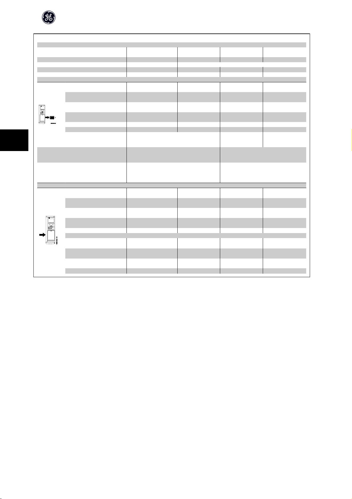
5
Mains Supply 3 x 525 - 600 VAC
AF-650 GP
High/ Normal
Load*
Output current
Max. input current
Typical Shaft Output [kW] 37 45 45 55 55 75 75 90
Typical Shaft Output [HP] at 575V
Unit Size IP21, 55, 66 31 31 31 32 32
Unit Size IP20 33 33 33 34 34
Continuous
(3 x 525-550 V ) [A]
Intermittent
(3 x 525-550 V ) [A]
Continuous
(3 x 525-600 V ) [A]
Intermittent
(3 x 525-600 V ) [A]
Continuous kVA (550 V AC) [kVA]
Continuous kVA (575 V AC) [kVA] 51.8 61.7 61.7 82.7 82.7 99.6 99.6 130.5
Max. cable size IP20
(mains, motor)
2)
[AWG]
[mm2]
Max. cable size IP20
(load share, brake)
2)
[AWG]
[mm2]
Max. cable size IP21, 55, 66
(mains, motor, load share and
brake)
2)
[mm2]
[AWG]
Continuous
at 550 V [A]
Intermittent
at 550 V [A]
Continuous
at 575 V [A]
Intermittent
at 575 V [A]
Max. pre-fuses
Environment
Estimated power loss
at rated max. load [W]
Weight,
Unit Size IP20 [kg]
Weight,
Unit Size IP21, 55 [kg]
Efficiency
AF-650 GP Operating Instructions
HO NO HO NO HO NO HO NO
50 60 60 74 74 100 100 120
54 65 65 87 87 105 105 137
81 72 98 96 131 116 158 151
52 62 62 83 83 100 100 131
78 68 93 91 125 110 150 144
51.4 61.9 61.9 82.9 82.9 100.0 100.0 130.5
50 (1) 95 (4/0) 150 (300mcm)
50 (1) 95 (4/0)
90 (3/0) 120 (4/0)
49 59 59 78.9 78.9 95.3 95.3 124.3
74 65 89 87 118 105 143 137
47 56 56 75 75 91 91 119
70 62 85 83 113 100 137 131
1)
[A]
4)
4)
850 1100 1400 1500
125 160 250 250
35 35 50 50
45 45 65 65
0.98 0.98 0.98 0.98
76
Page 78

AF-650 GP Operating Instructions
Mains supply (L1, L2, L3):
Supply voltage 200-240 V ±10%
Supply voltage 380-500 V ±10%
Supply voltage 525-690 V ±10%
Supply frequency 50/60 Hz
Max. imbalance temporary between mains phases 3.0 % of rated supply voltage
True Power Factor () ≥ 0.9 nominal at rated load
Displacement Power Factor (cos ϕ) near unity (> 0.98)
Switching on input supply L1, L2, L3 (power-ups) ≤ 7.5 kW maximum 2 times/min.
Switching on input supply L1, L2, L3 (power-ups) 11-75 kW maximum 1 time/min.
Switching on input supply L1, L2, L3 (power-ups) ≥ 90 kW maximum 1 time/2 min.
Environment according to EN60664-1 overvoltage category III/pollution degree 2
The unit is suitable for use on a circuit capable of delivering not more than 100,000 RMS symmetrical Amperes, 240/500/600/ 690 V maximum.
Motor output (U, V, W):
Output voltage 0 - 100% of supply voltage
Output frequency (0.25-75 kW) 0 - 1000 Hz
Output frequency (90-1000 kW) 0 - 800* Hz
Output frequency in Flux Mode 0 - 300 Hz
Switching on output Unlimited
Ramp times 0.01 - 3600 sec.
* Voltage and power dependent
5
Torque characteristics:
Starting torque (Constant torque) maximum 160% for 60 sec.
Starting torque maximum 180% up to 0.5 sec.
Overload torque (Constant torque) maximum 160% for 60 sec.
Starting torque (Variable torque) maximum 110% for 60 sec.
Overload torque (Variable torque) maximum 110% for 60 sec.
*Percentage relates to the nominal torque.
Digital inputs:
Programmable digital inputs 4 (6)
Terminal number 18, 19, 271), 291), 32, 33,
Logic PNP or NPN
Voltage level 0 - 24 V DC
Voltage level, logic'0' PNP < 5 V DC
Voltage level, logic'1' PNP > 10 V DC
Voltage level, logic '0' NPN
Voltage level, logic '1' NPN
Maximum voltage on input 28 V DC
Pulse frequency range 0 - 110 kHz
(Duty cycle) Min. pulse width 4.5 ms
Input resistance, R
2)
2)
i
> 19 V DC
< 14 V DC
approx. 4 k
*
*
*
*
77
Page 79

AF-650 GP Operating Instructions
Safe stop Terminal 372) (Terminal 37 is fixed PNP logic):
Voltage level 0 - 24 V DC
Voltage level, logic'0' PNP < 4 V DC
Voltage level, logic'1' PNP >20 V DC
Nominal input current at 24 V 50 mA rms
Nominal input current at 20 V 60 mA rms
Input capacitance 400 nF
All digital inputs are galvanically isolated from the supply voltage (PELV) and other high-voltage terminals.
1) Terminals 27 and 29 can also be programmed as output.
2) Terminal 37 is only available in AF-650 GP. It can only be used as safe stop input. Terminal 37 is suitable for category 3 installations according to EN 954-1 (safe
stop according to category 0 EN 60204-1) as required by the EU Machinery Directive 98/37/EC. Terminal 37 and the Safe Stop function are designed in conformance
with EN 60204-1, EN 50178, EN 61800-2, EN 61800-3, and EN 954-1. For correct and safe use of the Safe Stop function follow the related information and instructions
in the AF-650 GP Design Guide.
5
Analog inputs:
Number of analog inputs 2
Terminal number 53, 54
Modes Voltage or current
Mode select Switch S201 and switch S202
Voltage mode Switch S201/switch S202 = OFF (U)
Voltage level -10 to +10 V (scaleable)
Input resistance, R
Max. voltage ± 20 V
Current mode Switch S201/switch S202 = ON (I)
Current level 0/4 to 20 mA (scaleable)
Input resistance, R
Max. current 30 mA
Resolution for analog inputs 10 bit (+ sign)
Accuracy of analog inputs Max. error 0.5% of full scale
Bandwidth 100 Hz
The analog inputs are galvanically isolated from the supply voltage (PELV) and other high-voltage terminals.
i
i
approx. 10 k
approx. 200
78
Page 80

AF-650 GP Operating Instructions
Pulse/encoder inputs:
Programmable pulse/encoder inputs 2/1
Terminal number pulse/encoder 29, 331) / 322), 33
Max. frequency at terminal 29, 32, 33 110 kHz (Push-pull driven)
Max. frequency at terminal 29, 32, 33 5 kHz (open collector)
Min. frequency at terminal 29, 32, 33 4 Hz
Voltage level see section on Digital input
Maximum voltage on input 28 V DC
Input resistance, R
Pulse input accuracy (0.1 - 1 kHz) Max. error: 0.1% of full scale
Encoder input accuracy (1 - 110 kHz) Max. error: 0.05 % of full scale
The pulse and encoder inputs (terminals 29, 32, 33) are galvanically isolated from the supply voltage (PELV) and other high-voltage terminals.
1) Pulse inputs are 29 and 33
2) Encoder inputs: 32 = A, and 33 = B
Digital output:
Programmable digital/pulse outputs 2
Terminal number 27, 29
Voltage level at digital/frequency output 0 - 24 V
Max. output current (sink or source) 40 mA
Max. load at frequency output 1 k
Max. capacitive load at frequency output 10 nF
Minimum output frequency at frequency output 0 Hz
Maximum output frequency at frequency output 32 kHz
Accuracy of frequency output Max. error: 0.1 % of full scale
Resolution of frequency outputs 12 bit
1) Terminal 27 and 29 can also be programmed as input.
The digital output is galvanically isolated from the supply voltage (PELV) and other high-voltage terminals.
i
approx. 4 k
2)
5
1)
Analog output:
Number of programmable analog outputs 1
Terminal number 42
Current range at analog output 0/4 - 20 mA
Max. load GND - analog output 500
Accuracy on analog output Max. error: 0.5 % of full scale
Resolution on analog output 12 bit
The analog output is galvanically isolated from the supply voltage (PELV) and other high-voltage terminals.
Control card, 24 V DC output:
Terminal number 12, 13
Output voltage 24 V +1, -3 V
Max. load 200 mA
The 24 V DC supply is galvanically isolated from the supply voltage (PELV), but has the same potential as the analog and digital inputs and outputs.
Control card, 10 V DC output:
Terminal number 50
Output voltage 10.5 V ±0.5 V
Max. load 15 mA
The 10 V DC supply is galvanically isolated from the supply voltage (PELV) and other high-voltage terminals.
79
Page 81

AF-650 GP Operating Instructions
Control card, RS 485 serial communication:
Terminal number 68 (P,TX+, RX+), 69 (N,TX-, RX-)
Terminal number 61 Common for terminals 68 and 69
The RS 485 serial communication circuit is functionally separated from other central circuits and galvanically isolated from the supply voltage (PELV).
Control card, USB serial communication:
USB standard 1.1 (Full speed)
USB plug USB type B “device” plug
Connection to PC is carried out via a standard host/device USB cable.
The USB connection is galvanically isolated from the supply voltage (PELV) and other high-voltage terminals.
The USB ground connection is
converter.
Relay outputs:
5
Programmable relay outputs 2 Form C
Relay 01 Terminal number 1-3 (break), 1-2 (make)
Max. terminal load (AC-1)1) on 1-3 (NC), 1-2 (NO) (Resistive load) 240 V AC, 2 A
Max. terminal load (AC-15)1) (Inductive load @ cos 0.4) 240 V AC, 0.2 A
Max. terminal load (DC-1)1) on 1-2 (NO), 1-3 (NC) (Resistive load) 60 V DC, 1A
Max. terminal load (DC-13)1) (Inductive load) 24 V DC, 0.1A
Relay 02 Terminal number 4-6 (break), 4-5 (make)
Max. terminal load (AC-1)1) on 4-5 (NO) (Resistive load)
Max. terminal load (AC-15)1) on 4-5 (NO) (Inductive load @ cos 0.4) 240 V AC, 0.2 A
Max. terminal load (DC-1)1) on 4-5 (NO) (Resistive load) 80 V DC, 2 A
Max. terminal load (DC-13)1) on 4-5 (NO) (Inductive load) 24 V DC, 0.1A
Max. terminal load (AC-1)1) on 4-6 (NC) (Resistive load) 240 V AC, 2 A
Max. terminal load (AC-15)1) on 4-6 (NC) (Inductive load @ cos 0.4) 240 V AC, 0.2A
Max. terminal load (DC-1)1) on 4-6 (NC) (Resistive load) 50 V DC, 2 A
Max. terminal load (DC-13)1) on 4-6 (NC) (Inductive load) 24 V DC, 0.1 A
Min. terminal load on 1-3 (NC), 1-2 (NO), 4-6 (NC), 4-5 (NO) 24 V DC 10 mA, 24 V AC 20 mA
Environment according to EN 60664-1 overvoltage category III/pollution degree 2
1) IEC 60947 part 4 and 5
The relay contacts are galvanically isolated from the rest of the circuit by reinforced isolation (PELV).
2) Overvoltage Category II
3) UL applications 300 V AC 2A
not galvanically isolated from protection earth. Use onl y an isolated l aptop as P C connect ion to the USB conne ctor on th e frequency
2)3)
Overvoltage cat. II 400 V AC, 2 A
Cable lengths and cross sections for control cables*:
Max. motor cable length, screened 150 m
Max. motor cable length, unscreened 300 m
Maximum cross section to control terminals, flexible/ rigid wire without cable end sleeves 1.5 mm2/16 AWG
Maximum cross section to control terminals, flexible wire with cable end sleeves 1 mm2/18 AWG
Maximum cross section to control terminals, flexible wire with cable end sleeves with collar 0.5 mm2/20 AWG
Minimum cross section to control terminals 0.25 mm2/ 24 AWG
* Power cables, see tables in section “Electrical Data” of the AF-650 GP Design Guide
80
Page 82

AF-650 GP Operating Instructions
Control card performance:
Scan interval AF-650 GP: 1 ms
Control characteristics:
Resolution of output frequency at 0 - 1000 Hz +/- 0.003 Hz
Repeat accuracy of Precise start/stop (terminals 18, 19) ≤± 0.1 msec
System response time (terminals 18, 19, 27, 29, 32, 33) ≤ 2 ms
Speed control range (open loop) 1:100 of synchronous speed
Speed control range (closed loop) 1:1000 of synchronous speed
Speed accuracy (open loop) 30 - 4000 rpm: error ±8 rpm
Speed accuracy (closed loop), depending on resolution of feedback device 0 - 6000 rpm: error ±0.15 rpm
All control characteristics are based on a 4-pole asynchronous motor
Surroundings:
Enclosure IP20 Open Chassis, Nema 1 with field installed kit, Nema 12, and Nema 4
Vibration test 1.0 g
Max. relative humidity 5% - 93%(IEC 721-3-3; Class 3K3 (non-condensing) during operation
Aggressive environment (IEC 60068-2-43) H2S test
Ambient temperature Max. 50 °C
1) Only for ≤ 3.7 kW (200 - 240 V), ≤ 7.5 kW (400 - 480/ 500 V)
≤
2) As enclosure kit for
3) Derating for high ambient temperature, see special conditions in the Design Guide
Minimum ambient temperature during full-scale operation
Minimum ambient temperature at reduced performance - 10 °C
Temperature during storage/transport -25 - +65/70 °C
Maximum altitude above sea level without derating 1000 m
Derating for high altitude, see special conditions in the Design Guide
EMC standards, Emission
EMC standards, Immunity
See section on special conditions in the Design Guide. Please see www.geelectrical.com/drives for more information.
Protection and Features:
• Electronic thermal motor protection against overload.
• Temperature monitoring of the heatsink ensures that the frequency converter trips if the temperature reaches a predefined level. An overload temper-
ature cannot be reset until the temperature of the heatsink is below the values stated in the tables on the following pages (Guideline - these temperatures
may vary for different power sizes, Unit Sizes, enclosure ratings etc.).
• The frequency converter is protected against short-circuits on motor terminals U, V, W.
• If a mains phase is missing, the frequency converter trips or issues a warning (depending on the load).
• Monitoring of the intermediate circuit voltage ensures that the frequency converter trips if the intermediate circuit voltage is too low or too high.
• The frequency converter constantly checks for critical le vels of internal temperature, load current, high voltage on the inte rmediate circuit and low motor
speeds. As a response to a critical level, the frequency converter can adjust the switching frequency and/ or change the switching pattern in order to
ensure the performance of the drive.
3.7 kW (200 - 240 V), ≤ 7.5 kW (400 - 480/ 500 V)
EN 61800-3, EN 61000-6-3/4, EN 55011
EN 61800-3, EN 61000-6-1/2,
EN 61000-4-2, EN 61000-4-3, EN 61000-4-4, EN 61000-4-5, EN 61000-4-6
class Kd
0 °C
5
81
Page 83

6
AF-650 GP Operating Instructions
82
Page 84

AF-650 GP Operating Instructions
6 Troubleshooting
6.1.1 Warnings/Alarm Messages
A warning or an alarm is signalled by the relevant LED on the front of the frequency converter and indicated by a code on the display.
A warning remains active until its cause is no longer present. Under certain circumstances operation of the motor may still be continued. Warning messages may
be critical, but are not necessarily so.
In the event of an alarm, the frequency converter will have tripped. Alarms must be reset to restart operation once their cause has been rectified.
This may be done in three ways:
1. By using the [RESET] control button on the Keypad control panel.
2. Via a digital input with the “Reset” function.
3. Via serial communication/optional network.
NB!
After a manual reset using the [RESET] button on the Keypad, the [AUTO] button must be pressed to restart the motor.
If an alarm cannot be reset, the reason may be that its cause has not been rectified, or the alarm is trip-locked (see also table on following page).
Alarms that are trip-locked offer additional protection, meaning that the mains supply must be switched off before the alarm can be reset. After being switched
back on, the frequency converter is no longer blocked and may be reset as described above once the cause has been rectified.
Alarms that are not trip-locked can also be reset using the automatic reset function in par. H-04 Auto-Reset (Times) (Warning: automatic wake-up is possible!)
If a warning and alarm is marked against a code in the table on the following page, this means that either a warning occurs before an alarm, or else that you can
specify whether it is a warning or an alarm that is to be displayed for a given fault.
This is possible, for instance, in par. F-10 Electronic Overload. After an alarm or trip, the motor carries on coasting, and the alarm and warning flash. Once the
problem has been rectified, only the alarm continues flashing until the frequency converter is reset.
6
83
Page 85

AF-650 GP Operating Instructions
6
No. Description Warning Alarm/Trip Alarm/Trip Lock Parameter
1 10 Volts low X
2 Live zero error (X) (X) par. AN-01 Live Zero Time-
3 No motor (X) par. H-80 Function at Stop
4 Mains phase loss (X) (X) (X) par. SP-12 Function at Line
5 DC link voltage high X
6 DC link voltage low X
7 DC over-voltage X X
8 DC under voltage X X
9 Inverter overloaded X X
10 Motor Electronic OL over temperature (X) (X) par. F-10 Electronic Over-
11 Motor thermistor over temperature (X) (X) par. F-10 Electronic Over-
12 Torque limit X X
13 Over Current X X X
14 Earth Fault X X X
15 Hardware mismatch X X
16 Short Circuit X X
17 Control word time-out (X) (X) par. O-04 Control Word
22 Hoist Mech. Brake
23 Internal Fan Fault X
24 External Fan Fault X par. SP-53 Fan Monitor
25 Brake resistor short-circuited X
26 Brake resistor power limit (X) (X) par. B-13 Braking Thermal
27 Brake chopper short-circuited X X
28 Brake check (X) (X) par. B-15 Brake Check
29 Heatsink temp X X X
30 Motor phase U missing (X) (X) (X) par. H-78 Missing Motor
31 Motor phase V missing (X) (X) (X) par. H-78 Missing Motor
32 Motor phase W missing (X) (X) (X) par. H-78 Missing Motor
33 Inrush Fault X X
34 Network communication fault X X
36 Mains failure X X
38 Internal Fault X X
39 Heatsink sensor X X
40 Overload of Digital Output Terminal 27 (X) par. E-00 Digital I/O Mode,
41 Overload of Digital Output Terminal 29 (X) par. E-00 Digital I/O Mode,
42 Overload of Digital Output On X30/6 (X) par. E-56 Term X30/6 Digi
42 Overload of Digital Output On X30/7 (X) par. E-57 Term X30/7 Digi
46 Pwr. card supply X X
47 24 V supply low X X X
48 1.8 V supply low X X
49 Speed limit X
50 Auto Tune calibration failed X
51 Auto Tune check U
52 Auto Tune low I
53 Auto Tune motor too big X
nom
nom
and I
nom
X
X
Reference
out Function
Imbalance
load
load
Timeout Function
Overload
Phase Function
Phase Function
Phase Function
par. E-51 Terminal 27 Mode
par. E-52 Terminal 29 Mode
Out (OPCGPIO)
Out (OPCGPIO)
Table 6.1: Alarm/Warning code list
84
Page 86

AF-650 GP Operating Instructions
No. Description Warning Alarm/Trip Alarm/Trip Lock Parameter
54 Auto Tune motor too small X
55 Auto Tune parameter out of range X
56 Auto Tune interrupted by user X
57 Auto Tune time-out X
58 Auto Tune internal fault X X
59 Current limit X
61 Tracking Error (X) (X) par. H-20 Motor Feedback
62 Output Frequency at Maximum Limit X
63 Mechanical Brake Low (X) par. B-20 Release Brake
64 Voltage Limit X
65 Control Board Over-temperature X X X
66 Heat sink Temperature Low X
67 Option Module Configuration has Changed X
68 Safe Stop (X)
69 Pwr. Card Temp X X
70 Illegal Drive configuration X
71 Safe Stop X
72 Dangerous Failure
73 Safe Stop Auto Restart
77 Reduced power mode X par. SP-59 Actual Number
79 Illegal PS config X X
80 Drive Restored to Factory Settings X
81 CSIV corrupt
82 CSIV parameter error
85 Profibus/Profisafe Error
90 Encoder Loss (X) (X) par. EC-61 Feedback Sig-
91 Analog input 54 wrong settings X S202
243 Brake IGBT X X
244 Heatsink temp X X X
245 Heatsink sensor X X
246 Pwr.card supply X X
247 Pwr.card temp X X
248 Illegal PS config X X
250 New spare part X
251 New Model Number X X
1)
(X)
1)
X
1)
X
Reference
Loss Function
Current
par. E-07 Terminal 37 Safe
Stop
par. E-07 Terminal 37 Safe
Stop
par. E-07 Terminal 37 Safe
Stop
of Inverter Units
nal Monitoring
6
Table 6.2: Alarm/Warning code list
(X) Dependent on parameter
1) Can not be Auto reset via par. H-04 Auto-Reset (Times)
A trip is the action when an alarm has appeared. The trip will coast the motor and can be reset by pressing the reset button or make a reset by a digital input (Par.
E-1# [1]). The origin event that caused an alarm cannot damage the frequency converter or cause dangerous conditions. A trip lock is an action when an alarm
occurs, which may cause damage to frequency converter or connected parts. A Trip Lock situation can only be reset by a power cycling.
LED indication
Warning yellow
Alarm flashing red
Trip locked yellow and red
85
Page 87

6
AF-650 GP Operating Instructions
Alarm Word Extended Status Word
Bit Hex Dec Alarm Word Alarm Word 2 Warning Word Warning
0 00000001 1 Brake Check ServiceTrip, Read/
1 00000002 2 Pwr. Card Temp ServiceTrip, (re-
2 00000004 4 Earth Fault ServiceTrip, Type-
3 00000008 8 Ctrl.Card Temp ServiceTrip, (re-
4 00000010 16 Ctrl. Word TO ServiceTrip, (re-
5 00000020 32 Over Current Over Current Feedback High
6 00000040 64 Torque Limit Torque Limit Feedback Low
7 00000080 128 Motor Th Over Motor Th Over Output Current High
8 00000100 256 Motor Electronic OL
Over
9 00000200 512 Drive Overld. Drive Overld. Output Freq High
10 00000400 1024 DC under Volt DC under Volt Output Freq Low
11 00000800 2048 DC over Volt DC over Volt Brake Check OK
12 00001000 4096 Short Circuit DC Voltage Low Braking Max
13 00002000 8192 Inrush Fault DC Voltage High Braking
14 00004000 16384 Mains ph. Loss Mains ph. Loss Out of Speed Range
15 00008000 32768 Auto Tune Not OK No Motor OVC Active
16 00010000 65536 Live Zero Error Live Zero Error AC Brake
17 00020000 131072 Internal Fault KTY error 10V Low KTY Warn Password Timelock
18 00040000 262144 Brake Overload Fans error Brake Overload Fans Warn Password Protection
19 00080000 524288 U phase Loss ECB error Brake Resistor ECB Warn
20 00100000 1048576 V phase Loss Brake IGBT
21 00200000 2097152 W phase Loss Speed Limit
22 00400000 4194304 Network Fault Network Fault Unused
23 00800000 8388608 24 V Supply Low 24V Supply Low Unused
24 01000000 16777216 Mains Failure Mains Failure Unused
25 02000000 33554432 1.8V Supply Low Current Limit Unused
26 04000000 67108864 Brake Resistor Low Temp Unused
27 08000000 134217728 Brake IGBT Voltage Limit Unused
28 10000000 268435456 Option Change Encoder loss Unused
29 20000000 536870912 Drive Restored to
factory settings
30 40000000 1073741824 Safe Stop (A68) Safe Stop (A71) Safe Stop (W68) Safe Stop
31 80000000 2147483648 Mech. brake low Dangerous Failure
Write
served)
code/Sparepart
served)
served)
Output freq. lim. Unused
(A72)
Brake Check Ramping
Pwr. Card Temp Auto Tune Running
Earth Fault Start CW/CCW
Ctrl.Card Temp Slow Down
Ctrl. Word TO Catch Up
Motor Electronic OL Over Output Current Low
Extended Status Word Unused
Word 2
(W71)
Extended
Status Word
Unused
Table 6.3: Description of Alarm Word, Warning Word and Extended Status Word
The alarm words, warning words and extended status words can be read out via serial bus or optional network for diagnose. See alsopar. DR-94 Ext. Status
Word.
WARNING 1, 10 Volts low:
The 10 V voltage from terminal 50 on the control card is below 10 V.
Remove some of the load from terminal 50, as the 10 V supply is overloaded.
Max. 15 mA or minimum 590 .
WARNING/ALARM 2, Live zero error:
The signal on terminal 53 or 54 is less than 50% of the value set in par.
AN-10 Terminal 53 Low Voltage, par. AN-12 Terminal 53 Low Current, par.
AN-20 Terminal 54 Low Voltage, or par. AN-22 Terminal 54 Low Current re-
spectively.
WARNING/ALARM 3, No motor:
No motor has been connected to the output of the frequency converter.
WARNING/ALARM 4, Mains phase loss:
A phase is missing on the supply side, or the mains voltage imbalance is too
high.
This message also appears in case of a fault in the input rectifier on the fre-
quency converter.
Check the supply voltage and supply currents to the frequency converter.
WARNING 5, DC link voltage high:
The intermediate circuit voltage (DC) is higher than the overvoltage limit of
the control system. The frequency converter is still active.
WARNING 6, DC link voltage low
The intermediate circuit voltage (DC) is below the undervoltage limit of the
control system. The frequency converter is still active.
WARNING/ALARM 7, DC over voltage:
If the intermediate circuit voltage exceeds the limit, the frequency converter
trips after a time.
Possible corrections:
Connect a brake resistor
Extend the ramp time
Activate functions in par. B-10 Brake Function
Increase par. SP-26 Trip Delay at Drive Fault
86
Page 88

AF-650 GP Operating Instructions
Alarm/warning limits:
Undervoltage 185 373 532
Voltage warning low 205 410 585
Voltage warning
high (w/o brake - w/
brake)
Overvoltage 410 855 975
The voltages stated are the intermediate circuit v oltage of the frequency
converter with a tolerance of ± 5 %. The corresponding mains voltage
is the intermediate circuit voltage (DC-link) divided by 1.35
WARNING/ALARM 8, DC under voltage:
If the intermediate circuit voltage (DC) drops below the “voltage warning low”
limit (see table above), the frequency converter checks if 24 V backup supply
is connected.
If no 24 V backup supply is connected, the frequency converter trips after a
given time depending on the unit.
To check whether the supply voltage matches the frequency converter, see
General Specifications.
WARNING/ALARM 9, Drive overloaded:
The frequency converter is about to cut out because of an overload (too high
current for too long). The counter for electronic, thermal inverter protection
gives a warning at 98% and trips at 100%, while giving an alarm. You
not reset the frequency converter until the counter is below 90%.
The fault is that the frequency converter is overloaded by more than 100%
for too long.
WARNING/ALARM 10, Motor electronic overload over temperature:
According to the electronic thermal protection, the motor is too hot. You can
choose if you want the frequency converter to give a warning or an alarm
when the counter reaches 100% in par. F-10 Electronic Overload. The fault is
that the motor is overloaded by more than 100% for too long. Check that the
motor par. P-03 Motor Current is set correctly.
WARNING/ALARM 11, Motor thermistor over temp:
The thermistor or the thermistor connection is disconnected. You can choose
if you want the frequency converter to give a warning or an alarm when the
counter reaches 100% in par. F-10 Electronic Overload. Check that the ther-
mistor is connected correctly between terminal 53 or 54 (analog voltage input)
and terminal 50 (+ 10 V supply), or between terminal 18 or 19 (digital input
PNP only) and terminal 50. If aKTY sensoris used, check for correct connection
between terminal 54 and 55.
WARNING/ALARM 12, Torque limit:
The torque is higher than the value in par. F-40 Torque Limiter (Driving) (in
motor operation) or the torque is higher than the value in par. F-41 Tor-
que Limiter (Braking) (in regenerative operation).
WARNING/ALARM 13, Over Current:
The inverter peak current limit (approx. 200% of the rated current) is exceeded.
The warning will last approx. 8-12 sec., then the frequency converter trips and
issues an alarm. Turn off the frequency converter and check if the motor shaft
can be turned and if the motor size matches the frequency converter.
If extended mechanical brake control is selected, trip can be reset externally.
ALARM 14, Earth fault:
There is a discharge from the output phases to earth, either in the cable be-
tween the frequency converter and the motor or in the motor itself.
Turn off the frequency converter and remove the earth fault.
3 x 200 - 240 V 3 x 380 - 500 V 3 x 525 - 600 V
[VDC] [VDC] [VDC]
390/405 810/840 943/965
can-
ALARM 15, Incomplete hardware:
A fitted option is not handled by the present control board (hardware or soft-
ware).
ALARM 16, Short-circuit
There is short-circuiting in the motor or on the motor terminals.
Turn off the frequency converter and remove the short-circuit.
WARNING/ALARM 17, Control word timeout:
There is no communication to the frequency converter.
The warning will only be active when par. O-04 Control Word Timeout Func-
tion is NOT set to OFF.
If par. O-04 Control Word Timeout Function is set to Stop and Trip, a warning
appears and the frequency converter ramps down until it trips, while giving
an alarm.
par. O-03 Control Word Timeout Time could possibly be increased.
WARNING 23, Internal fan fault:
The fan warning function is an extra protection function that checks if the fan
is running / mounted. The fan warning can be disabled in par.
SP-53 Fan Monitor (set to [0] Disabled).
WARNING 24, External fan fault:
The fan warning function is an extra protection function that checks if the fan
is running / mounted. The fan warning can be disabled in par.
SP-53 Fan Monitor (set to [0] Disabled).
WARNING 25, Brake resistor short-circuited:
The brake resistor is monitored during operation. If it short-circuits, the brake
function is disconnected and the warning appears. The frequency converter
still works, but without the brake function. Turn off the frequency converter
and replace the brake resistor (see par. B-15 Brake Check).
ALARM/WARNING 26, Brake resistor power limit:
The power transmitted to the brake resistor is calculated as a percentage, as
a mean value over the last 120 s, on the basis of the resistance value of the
brake resistor (par. B-11 Brake Resistor (ohm)) and the intermediate circuit
voltage. The warning is active when the dissipated braking power is higher
than 90%. If Trip [2] has been selected in par. B-13 Braking Thermal Over-
load, the frequency converter cuts out and issues this alarm, when the
dissipated braking power is higher than 100%.
ALARM/ WARNING 27, Brake chopper fault:
The brake transistor is monitored during operation and if it short-circuits, the
brake function disconnects and the warning comes up. The frequency con-
verter is still able to run, but since the brake transistor has short-circuited,
substantial power is transmitted to the brake resistor, even if it is inactive.
Turn off the frequency converter and remove the brake resistor.
This alarm/ warning could also occur should the brake resistor overheat. Ter-
minal 104 to 106 are available as brake resistor. Klixon inputs, see section
Brake Resistor Temperature Switch.
Warning: There is a risk of substantial power being trans-
mitted to the brake resistor if the brake transistor is short-
circuited.
ALARM/WARNING 28, Brake check failed:
Brake resistor fault: the brake resistor is not connected/working.
ALARM 29, Drive over temperature:
If the drive type is IP20 Open Chassis, IP20 with Nema 1 kit, or Nema 1 the
cut-out temperature of the heat-sink is 95
cannot be reset, until the temperature of the heatsink is below 70
o
C +5 oC. The temperature fault
o
C +5 oC.
6
87
Page 89

AF-650 GP Operating Instructions
The fault could be:
- Ambient temperature too high
- Too long motor cable
ALARM 30, Motor phase U missing:
Motor phase U between the freq uency converter and the the motor is missing.
Turn off the frequency converter and check motor phase U.
ALARM 31, Motor phase V missing:
Motor phase V between the frequency converter and the motor is missing.
Turn off the frequency converter and check motor phase V.
ALARM 32, Motor phase W missing:
Motor phase W between the frequency converter and the motor is missing.
Turn off the frequency converter and check motor phase W.
ALARM 33, Inrush fault:
Too many power ups have o ccured within a short time period. See the chapter
General Specifications for the allowed number of power ups within one mi-
nute.
WARNING/ALARM 34, Network communication fault:
6
The network option card is not working correctly. Please check parameters
associated with the module and make sure module is properly inserted in Slot
A of the drive.
WARNING/ALARM 36, Mains failure:
This warning/alarm is only active if the supply voltage to the frequency con-
verter is lost and par. SP-10 Line failure is NOT set to OFF. Possible correction:
check the fuses/circuit breaker connected to the frequency converter
ALARM 38, Internal fault:
Internal drive fault. Please contact your GE supplier. Some typical alarm mes-
sages:
0 The serial port cannot be initialized. Serious hardware fail-
ure
256 The power EEPROM data is defected or outdated.
512 The control board EEPROM data is defected or outdated.
513 Communication time out Reading EEPROM data
514 Communication time out Reading EEPROM data
515 The Application Orientated Control cannot recognize the
EEPROM data
516 Cannot write write to the EEPROM because a write com-
mand is on progress
517 The write command is under time out
518 Failure in the EEPROM
519 Missing or invalid BarCode data in EEPROM 1024 – 1279
CAN telegram cannot be sent. (1027 indicate a possible
hardware failure)
1281 Digital Signal Processor flash time-out
1282 Power micro software version mismatch
1283 Power EEPROM data version mismatch
1284 Cannot read Digital Signal Processor software version
1299 Option SW in slot A is outdated
1300 Option SW in slot B is outdated
1311 Option SW in slot C0 is outdated
1312 Option SW in slot C1 is outdated
1315 Option SW in slot A is not supported (not allowed)
1316 Option SW in slot B is not supported (not allowed)
1317 Option SW in slot C0 is not supported (not allowed)
1318 Option SW in slot C1 is not supported (not allowed)
1536 An exception in the Application Orientated Control is reg-
istered. Debug information written in Keypad
1792 DSP watchdog is active. Debugging of power part data
Motor Orientated Control data not transferred correctly
2049 Power data restarted
2315 Missing SW version from power unit
2816 Stack overflow Control board module
2817 Scheduler slow tasks
2818 Fast tasks
2819 Parameter thread
2820 Keypad stack overflow
2821 Serial port overflow
2822 USB port overflow
3072-512
2
5376-6231Out of memory
WARNING 40, Overload of Digital Output Terminal 27
Check the load connected to terminal 27 or remove short-circuit connection.
Check par. E-00 Digital I/O Mode and par. E-51 Terminal 27 Mode.
WARNING 41, Overload of Digital Output Terminal 29:
Check the load connected to terminal 29 or remove short-circuit connection.
Check par. E-00 Digital I/O Mode and par. E-52 Terminal 29 Mode.
WARNING 42, Overload of Digital Output On X30/6 :
Check the load connected to X30/6 or remove short-circuit connection. Check
par. E-56 Term X30/6 Digi Out (OPCGPIO).
WARNING 42, Overload of Digital Output On X30/7 :
Check the load connected to X30/7 or remove short-circuit connection. Check
par. E-57 Term X30/7 Digi Out (OPCGPIO).
WARNING 47, 24 V supply low:
The external 24 V DC backup power supply may be overloaded, otherwise
Contact your GE supplier.
WARNING 48, 1.8 V supply low:
Contact your GE supplier.
WARNING 49, Speed limit:
The speed is not within the specified range in par. F-18 Motor Speed Low Limit
[RPM] and par. F-17 Motor Speed High Limit [RPM].
ALARM 50, Auto Tune calibration failed:
Contact your GE supplier.
ALARM 51, Auto Tune check Unom and Inom:
The setting of motor voltage, motor current, and motor power are set set
correctly. Please check parameters (P-##).
ALARM 52, Auto Tune low Inom:
The motor current is too low. Check the settings.
ALARM 53, Auto Tune motor too big:
The motor is too big for the Auto Tune to be carried out.
ALARM 54, Auto Tune motor too small:
The motor is too small for the Auto Tune to be carried out.
ALARM 55, Auto Tune par. out of range:
The motor parameter values set for the motor are outside acceptable range.
ALARM 56, Auto Tune interrupted by user:
The Auto Tune has been interrupted by the user.
ALARM 57, Auto Tune timeout:
Try to start the Auto Tune again a number of times, until the Auto Tune is
carried out. Please note that repeated runs may heat the motor to a level
where the resistance Rs and Rr are increased. In most cases, however, this is
not critical.
Parameter value is outside its limits. Perform a initialization.
Parameter number causing the alarm: Subtract the code
from 3072. Ex Error code 3238: 3238-3072 = 166 is outside
the limit
5123 Option in slot A: Hardware incompatible wi th Control board
hardware
5124 Option in slot B: Hardware incompatible with Control board
hardware
5125 Option in slot C0: Hardware incompatible with Control
board hardware
5126 Option in slot C1: Hardware incompatible with Control
board hardware
88
Page 90

AF-650 GP Operating Instructions
ALARM 58, Auto Tune internal fault:
Contact your GE supplier.
WARNING 59, Current limit:
The current is higher than the value in par. F-43 Current Limit.
WARNING 61, Tracking Error:
An error has been detected between calculated speed and speed measure-
ment from feedback device. The function Warning/Alarm/Disabling setting is
in par. H-20 Motor Feedback Loss Function. Accepted error setting in par.
H-21 Motor Feedback Speed Error and the allowed time the error occur setting
in par. H-22 Motor Feedback Loss Timeout. During a commissioning procedure
the function may be effective.
WARNING 62, Output Frequency at Maximum Limit:
The output frequency is higher than the value set in par. F-03 Max Output
Frequency 1
ALARM 63, Mechanical Brake Low:
The actual motor current has not exceeded the “release brake” current within
the “Start delay” time window.
WARNING 64, Voltage Limit:
The load and speed combination demands a motor voltage higher than the
actual DC link voltage.
WARNING/ALARM/TRIP 65, Control Card Over Temperature:
Control card over temperature: The cut-out temperature of the control card
is 80° C.
WARNING 66, Heatsink Temperature Low:
The heat sink temperature is measured as 0° C. This could indicate that the
temperature sensor is defect and thus the fan speed is increased to the max-
imum in case the power part or control card is very hot.
ALARM 67, Option Module Configuration has Changed:
One or more options modules have either been added or removed since the
last power down.
ALARM 68, Safe Stop:
Safe Stop has been activated. To resume normal operation, apply 24 V DC to
terminal # 37,, then send a reset signal (via Bus, Digital I/O, or by pressing
[RESET]).
WARNING 68, Safe Stop:
Safe Stop has been activated. Normal operation is resumed when Safe Stop
is disabled. Warning: Automatic Restart!
ALARM 70, Illegal Drive Configuration:
Actual combination of control board and power board is illegal.
ALARM 71, 1 Safe Stop:
Safe Stop has been activated from external source. Normal operation can be
resumed when 24V dc is applied to terminal # 37. When that happens, a reset
signal must be is be sent (via Bus, Digital I/O, or by pressing [RESET]).
WARNING 71, Safe Stop:
Safe Stop has been activated from external source. Normal operation can be
resumed when 24V dc is applied to terminal # 37.. Warning: Automatic Re-
start.
ALARM 72, Dangerous Failure:
Safe Stop with Trip Lock. Unexpected signal levels on Safe Stop.
ALARM 80, Drive Restored to Factory Settings:
Parameter settings are restored to factory settings after a manual (three-
finger) reset.
ALARM 90, Encoder loss:
Check the connection to encoder option and eventually replace the OPCENC
or MCB 103.
ALARM 91, Analogue Input 54 Wrong Settings:
Switch S202 has to be set in position OFF (voltage input) when a KTY sensor
is connected to analogue input terminal 54.
ALARM 250, New Spare Part:
The power or Switch Mode Power Supply has been exchanged. The frequency
converter model number must be restored in the EEPROM. Remember to se-
lect ‘Save to EEPROM’ to complete.
ALARM 251, New Model Number:
The Frequency Converter has got a new model number.
6
89
Page 91

AF-650 GP Operating Instructions
Index
A
Abbreviations 4
Accel Time 1 40
Access To Control Terminals 25
Alarm Messages 83
Analog Inputs 78
Analog Output 79
Approvals 3
Auto Tune 32, 44
B
Base Frequency 39
Brake Control 87
C
Cable Lengths And Cross Sections 80
Cable Lengths And Cross Sections-continued 81
Connection To Mains 17
Control Cables 30
Control Cables 29
Control Card Performance 81
Control Card, +10 V Dc Output 79
Control Card, 24 V Dc Output 79
Control Card, Rs 485 Serial Communication 79
Control Card, Usb Serial Communication 80
Control Characteristics 81
Control Terminals 26
Cooling 41
Cooling Conditions 14
D
Dc Backup 3
Dc Link 86
Dct 10 3
Decel Time 1 41
Decoupling Plate 19
Devicenet 3
Digital Inputs: 77
Digital Output 79
Disposal Instruction 5
E
Electrical Installation 26, 29
Electrical Terminals 29
Electronic Overload 87
Electronic Overload 41
F
Frequency Setting 1 40
Fuses 22
G
General Warning 6
Graphical Display 37
I
Intermediate Circuit 86
Ip21 / Nema 1 Kit 3
90
Page 92

AF-650 GP Operating Instructions
K
Kty Sensor 87
L
Language 39
Language Package 1 0, 0
Language Package 2 0
Language Package 3 0
Language Package 4 0
Leakage Current 6
Leds 37
M
Main Reactance 0
Mains Supply 69, 74, 75, 76
Mains Supply (l1, L2, L3) 77
Mechanical Brake Control 34
Mechanical Dimensions 10
Mechanical Mounting 14
Motor Connection 19
Motor Current 40
Motor Name Plate 32
Motor Output 77
Motor Power [hp] 39
Motor Power [kw] 39
Motor Protection 41, 81
Motor Rated Voltage 39
Motor Speed Unit 39
Motor Thermal Protection 34
N
Name Plate Data 32
Non Ul Compliance 22
O
Output Performance (u, V, W) 77
P
Panel Through Mounting 15
Parallel Connection Of Motors 34
Potentiometer Reference 28
Profibus 3
Protection 22
Protection And Features 81
Pulse Start/stop 27
Pulse/encoder Inputs 79
R
Reference Site, 3-13 40
Relay Outputs 80
Removal Of Knockouts For Extra Cables 16
Repair Work 7
Residual Current Device 6
S
Safe Stop 7
Safety Precautions 6
Screened/armoured 30
Serial Communication 80
Speed Up/down 28
Start/stop 27
91
Page 93

AF-650 GP Operating Instructions
Stator Leakage Reactance 0
Status Messages 37
Surroundings 81
Switches S201, S202, And S801 31
Symbols 4
T
Thermistor 41
Torque Characteristics 77
U
Unintended Start 7
V
Voltage Level 77
Voltage Reference Via A Potentiometer 28
W
Warnings 83
92
Page 94

 Loading...