

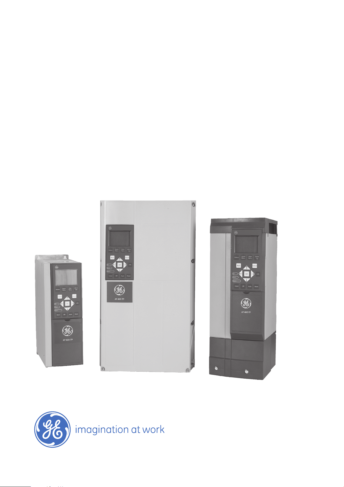
GE Consumer & Industrial
Electrical Distribution
AF-600 FP
TM
Fan and Pump Drive
Design Guide

Contents
AF-600 FP Design Guide
1 How to Read this Design Guide
Copyright, Limitation of Liability and Revision Rights 3
Approvals 4
Symbols 4
Abbreviations 5
Definitions 5
2 Introduction to AF-600 FP
Safety 11
CE Labelling 13
Aggressive Environments 14
Vibration and Shock 15
Application Examples 22
Control Structures 28
General Aspects of EMC 35
Galvanic Isolation (PELV) 39
PELV - Protective Extra Low Voltage 39
Earth Leakage Current 40
3
11
Extreme Running Conditions 40
3 AF-600 FP Selection
Options and Accessories 45
4 How to Install
Mechanical Dimensions 59
Lifting 64
Electrical Installation 66
Electrical Installation and Control Cables 67
Final Set-Up and Test 82
Additional Connections 84
Motor Insulation 86
Motor Bearing Currents 87
Installation of Misc. Connections 88
Safety 90
EMC-correct Installation 90
Residual Current Device 93
45
57
5 Application Examples
Start/Stop 95
Pulse Start/Stop 95
Potentiometer Reference 96
95
1

AF-600 FP Design Guide
Auto Tune 96
Logic Controller 96
Logic Controller Programming 97
LC Application Example 97
BASIC Cascade Controller 99
Pump Staging with Lead Pump Alternation 100
System Status and Operation 100
Fixed Variable Speed Pump Wiring Diagram 101
Lead Pump Alternation Wiring Diagram 102
Cascade Controller Wiring Diagram 103
Start/Stop Conditions 103
6 RS-485 Installation and Set-up
RS-485 Installation and Set-up 105
Drive Protocol Overview 107
Network Configuration 109
Drive Protocol Message Framing Structure 109
Examples 114
Modbus RTU Overview 116
Modbus RTU Message Framing Structure 117
How to Access Parameters 121
Examples 122
GE Drive Control Profile 128
7 General Specifications and Troubleshooting
Mains Supply Tables 133
General Specifications 145
Efficiency 149
Acoustic Noise 150
Peak Voltage on Motor 150
105
133
Special Conditions 155
Troubleshooting 157
Alarms and Warnings 157
Alarm Words 161
Warning Words 162
Extended Status Words 163
Fault Messages 164
Index
169
2
1 How to Read this Design Guide
AF-600 FP
Software version: 1.02
AF-600 FP Design Guide
1
This guide can be used with all AF-600 FP frequency converters with
software version 1.02 or later.
The actual software version number can be read from
par. ID-43 Software Version.
1.1.1 Copyright, Limitation of Liability and Revision Rights
This publication contains information proprietary to GE. By accepting and using this manual the user agrees that the information contained herein will be used
solely for operating equipment from GE or equipment from other vendors provided that such equipment is intended for communication with GE equipment over
a serial communication link. This publication is protected under the Copyright laws of Denmark and most other countries.
GE does not warrant that a software program produced according to the guidelines provided in this manual will function properly in every physical, hardware or
software environment.
Although GE has tested and reviewed the documentation within this manual, GE makes no warranty or representation, neither expressed nor implied, with respect
to this documentation, including its quality, performance, or fitness for a particular purpose.
In no event shall GE be liable for direct, indirect, special, incidental, or consequential damages arising out of the use, or the inability to use information contained
in this manual, even if advised of the possibility of such damages. In particular, GE is not responsible for any costs, including but not limited to those incurred as
a result of lost profits or revenue, loss or damage of equipment, loss of computer programs, loss of data, the costs to substitute these, or any claims by third
parties.
GE reserves the right to revise this publication at any time and to make changes to its contents without prior notice or any obligation to notify former or present
users of such revisions or changes.
3
1.1.2 Available Literature for AF-600 FP
AF-600 FP Design Guide
1
- Operating Instructions provide the necessary information for getting the drive up and running.
- Design Guide entails all technical information about the drive and customer design and applications.
- Programming Guide provides information on how to program and includes complete parameter descriptions.
GE technical literature is available in print from your local GE Sales Office or online at: www.geelectrical.com/drives
- AF-600 FP Built-in network manuals are available separately.
1.1.3 Approvals
1.1.4 Symbols
Symbols used in this guide.
NB!
Indicates something to be noted by the reader.
Indicates a general warning.
Indicates a high-voltage warning.
Indicates default setting
*
4

1.1.5 Abbreviations
AF-600 FP Design Guide
Alternating current AC
American wire gauge AWG
Ampere/AMP A
Current limit I
Degrees Celsius °C
Direct current DC
Drive Control Tool PC Software DCT 10
Drive Dependent D-TYPE
Electro Magnetic Compatibility EMC
Electronic Thermal Overload Elec. OL
Gram g
Hertz Hz
Kilohertz kHz
Meter m
Millihenry Inductance mH
Milliampere mA
Millisecond ms
Minute min
Nanofarad nF
Newton Meters Nm
Nominal motor current I
Nominal motor frequency f
Nominal motor power P
Nominal motor voltage U
Parameter par.
Protective Extra Low Voltage PELV
Printed Circuit Board PCB
Rated Inverter Output Current I
Revolutions Per Minute RPM
Regenerative terminals Regen
Second s
Synchronous Motor Speed n
Torque limit T
Volts V
LIM
M,N
M,N
M,N
M,N
INV
s
LIM
1
1.1.6 Definitions
Drive:
I
DRIVE,MAX
The maximum output current.
I
DRIVE,N
The rated output current supplied by the frequency converter.
U
DRIVE, MAX
The maximum output voltage.
Input:
Control command
You can start and stop the connected motor by means of keypad and the
digital inputs.
Functions are divided into two groups.
Functions in group 1 have higher priority than functions in group 2.
Group 1
Group 2
Reset, Coasting stop, Reset and Coasting stop, Quick-stop, DC braking, Stop and the "Off" key.
Start, Pulse start, Reversing, Start reversing, Jog and Freeze output
5
Motor:
f
1
JOG
The motor frequency when the jog function is activated (via digital terminals).
f
M
The motor frequency.
f
MAX
The maximum motor frequency.
f
MIN
The minimum motor frequency.
f
M,N
The rated motor frequency (nameplate data).
I
M
The motor current.
I
M,N
The rated motor current (nameplate data).
AF-600 FP Design Guide
n
M,N
The rated motor speed (nameplate data).
P
M,N
The rated motor power (nameplate data).
T
M,N
The rated torque (motor).
U
M
The instantaneous motor voltage.
U
M,N
The rated motor voltage (nameplate data).
Break-away torque
DRIVE
The efficiency of the frequency converter is defined as the ratio between the power output and the power input.
6

Start-disable command
A stop command belonging to the group 1 control commands - see this group.
AF-600 FP Design Guide
Stop command
See Control commands.
References:
Analog Reference
A signal transmitted to the analog inputs 53 or 54, can be voltage or current.
Bus Reference
A signal transmitted to the serial communication port (drive port).
Preset Reference
A defined preset reference to be set from -100% to +100% of the reference range. Selection of eight preset references via the digital terminals.
Pulse Reference
A pulse frequency signal transmitted to the digital inputs (terminal 29 or 33).
Ref
MAX
Determines the relationship between the reference input at 100% full scale value (typically 10 V, 20mA) and the resulting reference. The maximum reference value
set in par. F-53 Maximum Reference.
Ref
MIN
Determines the relationship between the reference input at 0% value (typically 0V, 0mA, 4mA) and the resulting reference. The minimum reference value set in
par. F-52 Minimum Reference
1
Miscellaneous:
Advanced Vecter Control
If compared with standard voltage/frequency ratio control, Advanced Vecter Control improves the dynamics and the stability, both when the speed reference is
changed and in relation to the load torque.
Analog Inputs
The analog inputs are used for controlling various functions of the frequency converter.
There are two types of analog inputs:
Current input, 0-20 mA and 4-20 mA
Voltage input, 0-10 V DC.
Analog Outputs
The analog outputs can supply a signal of 0-20 mA, 4-20 mA, or a digital signal.
Auto Tune
Auto Tune algorithm determines the electrical parameters for the connected motor at standstill.
CT Characteristics
Constant torque characteristics used for screw and scroll refrigeration compressors.
Digital Inputs
The digital inputs can be used for controlling various functions of the frequency converter.
Digital Outputs
The frequency converter features two Solid State outputs that can supply a 24 V DC (max. 40 mA) signal.
7

AF-600 FP Design Guide
DSP
Digital Signal Processor.
1
Relay Outputs:
The frequency converter features two programmable Relay Outputs.
Electronic Thermal Overload
Electronic Thermal Overload is a thermal load calculation based on present load and time. Its purpose is to estimate the motor temperature.
Initialising
If initialising is carried out (par. H-03 Restore Factory Settings), the programmable parameters of the frequency converter return to their default settings.
Intermittent Duty Cycle
An intermittent duty rating refers to a sequence of duty cycles. Each cycle consists of an on-load and an off-load period. The operation can be either periodic duty
or none-periodic duty.
keypad
The keypad makes up a complete interface for control and programming of the frequency converter. The is detachable and can be installed up to 3 metres from
the frequency converter, i.e. in a front panel by means of the installation kit option.
lsb
Least significant bit.
MCM
2
Short for Mille Circular Mil, an American measuring unit for cable cross-section. 1 MCM ≡ 0.5067 mm
msb
Most significant bit.
On-line/Off-line Parameters
Changes to on-line parameters are activated immediately after the data value is changed. Changes to off-line parameters are not activated until you enter [OK]
on the keypad.
PID Controller
The PID controller maintains the desired speed, pressure, temperature, etc. by adjusting the output frequency to match the varying load.
RCD
Residual Current Device.
Set-up
You can save parameter settings in four Set-ups. Change between the four parameter Set-ups and edit one Set-up, while another Set-up is active.
SFAVM
Switching pattern called
Slip Compensation
The frequency converter compensates for the motor slip by giving the frequency a supplement that follows the measured motor load keeping the motor speed
almost constant.
Stator Flux oriented Asynchronous V ector M odulation (par. F-37 Adv. Switching Pattern).
.
Logic Controller (LC)
The LC is a sequence of user defined actions executed when the associated user defined events are evaluated as true by the LC.
Thermistor:
A temperature-dependent resistor placed where the temperature is to be monitored (frequency converter or motor).
8

AF-600 FP Design Guide
Trip
A state entered in fault situations, e.g. if the frequency converter is subject to an over-temperature or when the frequency converter is protecting the motor,
process or mechanism. Restart is prevented until the cause of the fault has disappeared and the trip state is cancelled by activating reset or, in some cases, by
being programmed to reset automatically. Trip may not be used for personal safety.
Trip Locked
A state entered in fault situations when the frequency converter is protecting itself and requiring physical intervention, e.g. if the frequency converter is subject
to a short circuit on the output. A locked trip can only be cancelled by cu tting off mains, removing the cause of the fault, and reconnecting th e frequency converter.
Restart is prevented until the trip state is cancelled by activating reset or, in some cases, by being programmed to reset automatically. Trip locked may not be
used for personal safety.
VT Characteristics
Variable torque characteristics used for pumps and fans.
60° AVM
Switching pattern called 60°
1.1.7 Power Factor
Asynchronous Vector Modulation (See par. F-37 Adv. Switching Pattern).
1
The power factor is the relation between I1 and I
The power factor for 3-phase control:
The power factor indicates to which extent the frequency converter imposes
a load on the mains supply.
The lower the power factor, the higher the I
In addition, a high power factor indicates that the different harmonic currents are low.
The frequency converters' built-in DC coils produce a high power factor, which minimizes the imposed load on the mains supply.
.
RMS
for the same kW performance.
RMS
Power factor
I
cos
×
1
=
I
RMS
I
RMS
2
=
I
1
=
ϕ1
+
3 × U ×
3 × U ×
I
1
=
I
RMS
2
+
I
I
5
since cos
2
+ . . +
7
I
1 ×
COS
I
RMS
ϕ1=1
2
I
n
ϕ
9

2
AF-600 FP Design Guide
10
2 Introduction to AF-600 FP
2.1 Safety
AF-600 FP Design Guide
2.1.1 Safety Note
The voltage of the frequency converter is dangerous whenever connected to mains. Incorrect installation of the motor, frequency converter
or network may cause death, serious personal injury or damage to the equipment. Consequently, the instructions in this manual, as well as
national and local rules and safety regulations, must be complied with.
Safety Regulations
1. The frequency converter must be disconnected from mains if repair work is to be carried out. Check that the mains supply has been disconnected and
that the necessary time has passed before removing motor and mains plugs.
2. The [STOP/RESET] key on the keypad of the frequency converter does not disconnect the equipment from mains and is thus not to be used as a safety
switch.
3. Correct protective earthing of the equipment must be established, the user must be protected against supply voltage, and the motor must be protected
against overload in accordance with applicable national and local regulations.
4. The earth leakage currents are higher than 3.5 mA.
5. Protection against motor overload is set by par. F-10 Electronic Overload . If this function is desired, set par. F-10 Electronic Overload to data value
[Electronic Thermal Overload trip] (default value) or data value [Electronic Thermal Overload warning]. Note: The function is initialized at 1.16 x rated
motor current and rated motor frequency. For the North American market: The Electronic Thermal Overload functions provide class 20 motor overload
protection in accordance with NEC.
6. Do not remove the plugs for the motor and mains supply while the frequency converter is connected to mains. Check that the mains supply has been
disconnected and that the necessary time has passed before removing motor and mains plugs.
7. Please note that the frequency converter has more voltage inputs than L1, L2 and L3, when load sharing (linking of DC intermediate circuit) and external
24 V DC have been installed. Check that all voltage inputs have been disconnected and that the necessary time has passed before commencing repair
work.
Installation at high altitudes
Installation at high altitude:
380 - 480 V, unit sizes 1x, 2x and 3x: At altitudes above 2 km, please contact GE regarding PELV.
380 - 480 V, unit sizes 4x, 5x and 6x: At altitudes above 3 km, please contact GE regarding PELV.
525 - 690 V: At altitudes above 2 km, please contact GE regarding PELV.
2
Warning against Unintended Start
1. The motor can be brought to a stop by means of digital commands, bus commands, references or a local stop, while the frequency converter is connected
to mains. If personal safety considerations make it necessary to ensure that no unintended start occurs, these stop functions are not sufficient.
2. While parameters are being changed, the motor may start. Consequently, the stop key [STOP/RESET] must always be activated; following which data
can be modified.
3. A motor that has been stopped may start if faults occur in the electronics of the frequency converter, or if a temporary overload or a fault in the supply
mains or the motor connection ceases.
Warning:
Touching the electrical parts may be fatal - even after the equipment has been disconnected from mains.
Also make sure that other voltage inputs have been disconnected, such as external 24 V DC, load sharing (linkage of DC intermediate circuit), as well as the motor
connection for kinetic back up. Refer to the Operating Instructions for further safety guidelines.
11

2
AF-600 FP Design Guide
2.1.2 Caution
The frequency converter DC link capacitors remain charged after power has been disconnected. To avoid an electrical shock hazard, disconnect
the frequency converter from the mains before carrying out maintenance. Wait at least as follows before doing service on the frequency
converter:
Voltage (V) Min. Waiting Time (Minutes)
4 15 20 30 40
200 - 240 1.1 - 3.7 kW 5.5 - 45 kW
380 - 480 1.1 - 7.5 kW 11 - 90 kW 110 - 250 kW 315 - 1000 kW
525 - 600 1.1 - 7.5 kW 11 - 90 kW
525 - 690 110 - 400 kW 450 - 1200 kW
Be aware that there may be high voltage on the DC link even when the LEDs are turned off.
12

AF-600 FP Design Guide
2.1.3 Disposal Instruction
Equipment containing electrical components may not be disposed of together with domestic waste.
It must be separately collected with electrical and electronic waste according to local and currently
valid legislation.
2.2 CE Labelling
2.2.1 CE Conformity and Labelling
What is CE Conformity and Labelling?
The purpose of CE labelling is to avoid technical trade obstacles within EFTA and the EU. The EU has introduced the CE label as a simple way of showing whether
a product complies with the relevant EU directives. The CE label says nothing about the specifications or quality of the product. Frequency converters are regulated
by three EU directives:
The machinery directive (98/37/EEC)
All machines with critical moving parts are covered by the machinery directive of January 1, 1995. Since a frequency converter is largely electrical, it does not fall
under the machinery directive. However, if a frequency converter is supplied for use in a machine, we provide information on safety aspects relating to the
frequency converter. We do this by means of a manufacturer's declaration.
The low-voltage directive (73/23/EEC)
Frequency converters must be CE labelled in accordance with the low-voltage directive of January 1, 1997. The directive applies to all electrical equipment and
appliances used in the 50 - 1000 V AC and the 75 - 1500 V DC voltage ranges. GE CE-labels in accordance with the directive and issues a declaration of conformity
upon request.
The EMC directive (89/336/EEC)
EMC is short for electromagnetic compatibility. The presence of electromagnetic compatibility means that the mutual interference between different components/
appliances does not affect the way the appliances work.
The EMC directive came into effect January 1, 1996. GE CE-labels in accordance with the directive and issues a declaration of conformity upon request. To carry
out EMC-correct installation, see the instructions in this Design Guide. In addition, we specify which standards our products comply with. We offer the filters
presented in the specifications and provide other types of assistance to ensure the optimum EMC result.
2
The frequency converter is most often used by professionals of the trade as a complex component forming part of a larger appliance, system or installation. It
must be noted that the responsibility for the final EMC properties of the appliance, system or installation rests with the installer.
2.2.2 What Is Covered
The EU "Guidelines on the Application of Council Directive 89/336/EEC" outline three typical situations of using a frequency converter. See below for EMC coverage
and CE labelling.
1. The frequency converter is sold directly to the end-consumer. The frequency converter is for example sold to a DIY market. The end-consumer is a
layman. He installs the frequency converter himself for use with a hobby machine, a kitchen appliance, etc. For such applications, the frequency converter
must be CE labelled in accordance with the EMC directive.
2. The frequency converter is sold for installation in a plant. The plant is built up by professionals of the trade. It could be a production plant or a heating/
ventilation plant designed and installed by professionals of the trade. Neither the frequency converter nor the finished plant has to b e CE lab elled und er
the EMC directive. However, the unit must comply with the basic EMC requirements of the directive. This is ensured by using components, appliances,
and systems that are CE labelled under the EMC directive.
3. The frequency converter is sold as part of a complete system. The system is being marketed as complete and could e.g. be an air-conditioning system.
The complete system must be CE labelled in accordance with the EMC directive. The manufacturer can ensure CE labelling under the EMC directive either
by using CE labelled components or by testing the EMC of the system. If he chooses to use only CE labelled components, he does not have to test the
entire system.
13

AF-600 FP Design Guide
2.2.3 GE Frequency Converter and CE Labelling
CE labelling is a positive feature when used for its original purpose, i.e. to facilitate trade within the EU and EFTA.
However, CE labelling may cover many different specifications. Thus, you have to check what a given CE label specifically covers.
2
The covered specifications can be very different and a CE label may therefore give the installer a false feeling of security when using a frequency converter as a
component in a system or an appliance.
GE CE labels the frequency converters in accordance with the low-voltage directive. This means that if the frequency converter is installed correctly, we guarantee
compliance with the low-voltage directive. GE issuesWe issue a declaration of conformity that confirms our CE labelling in accordance with the low-voltage
directive.
The CE label also applies to the EMC directive provided that the instructions for EMC-correct installation and filtering are followed. On this basis, a declaration of
conformity in accordance with the EMC directive is issued.
The Design Guide offers detailed instructions for installation to ensure EMC-correct installation. Furthermore, GE specifies which our different products comply
with.
GE provides other types of assistance that can help you obtain the best EMC result.
2.2.4 Compliance with EMC Directive 89/336/EEC
As mentioned, the frequency converter is mostly used by professionals of the trade as a complex component forming part of a larger appliance, system, or
installation. It must be noted that the responsibility for the final EMC properties of the appliance, system or installation rests with the installer. As an aid to the
installer, GE has prepared EMC installation guidelines for the Power Drive system. The standards and test levels stated for Power Drive systems are complied with,
provided that the EMC-correct instructions for installation are followed, see the section EMC Immunity.
The frequency converter has been designed to meet the IEC/EN 60068-2-3 standard, EN 50178 pkt. 9.4.2.2 at 50°C.
2.4.1 Aggressive Environments
A frequency converter contains a large number of mechanical and electronic components. All are to some extent vulnerable to environmental effects.
The frequency converter should not be installed in environments with airborne liquids, particles, or gases capable of affecting and damaging
the electronic components. Failure to take the necessary protective measures increases the risk of stoppages, thus reducing the life of the
frequency converter.
Liquids can be carried through the air and condense in the frequency converter and may cause corrosion of components and metal parts. Steam, oil, and salt
water may cause corrosion of components and metal parts. In such environments, use equipment with Unit Size rating IP 54/55. As an extra protection, coated
printed circuit boards can be ordered as an option.
Airborne
Particles such as dust may cause mechanical, electrical, or thermal failure in the frequency converter. A typical indicator of excessive levels of airborne
particles is dust particles around the frequency converter fan. In very dusty environments, use equipment with Unit Size rating IP 54/55 or a cabinet for IP 00/IP
20/TYPE 1 equipment.
In environments with high temperatures and humidity,
frequency converter components.
Such chemical reactions will rapidly affect and damage the electronic components. In such environments, mount the equipment in a cabinet with fresh air
ventilation, keeping aggressive gases away from the frequency converter.
An extra protection in such areas is a coating of the printed circuit boards, which can be ordered as an option.
corrosive gases such as sulphur, nitrogen, and chlorine compounds will cause chemical processes on the
14
AF-600 FP Design Guide
NB!
Mounting frequency converters in aggressive environments increases the risk of stoppages and considerably reduces the life of the converter.
Before installing the frequency converter, check the ambient air for liquids, particles, and gases. This is done by observing existing installations in this environment.
Typical indicators of harmful airborne liquids are water or oil on metal parts, or corrosion of metal parts.
Excessive dust particle levels are often found on installation cabinets and existing electrical installations. One in dicator of aggressive airborne gases is blackening
of copper rails and cable ends on existing installations.
NB!
Unit Sizes 4x and 5x have a stainless steel back-channel option to provide additional protection in aggressive environments. Proper ventilation is still required
for the internal components of the drive. Contact GE for additional information.
2.5 Vibration and Shock
The frequency converter has been tested according to the procedure based on the shown standards:
The frequency converter complies with requirements that exist for units mounted on the walls and floors of production premises, as well as in panels bolted to
walls or floors.
2
IEC/EN 60068-2-6: Vibration (sinusoidal) - 1970
IEC/EN 60068-2-64: Vibration, broad-band random
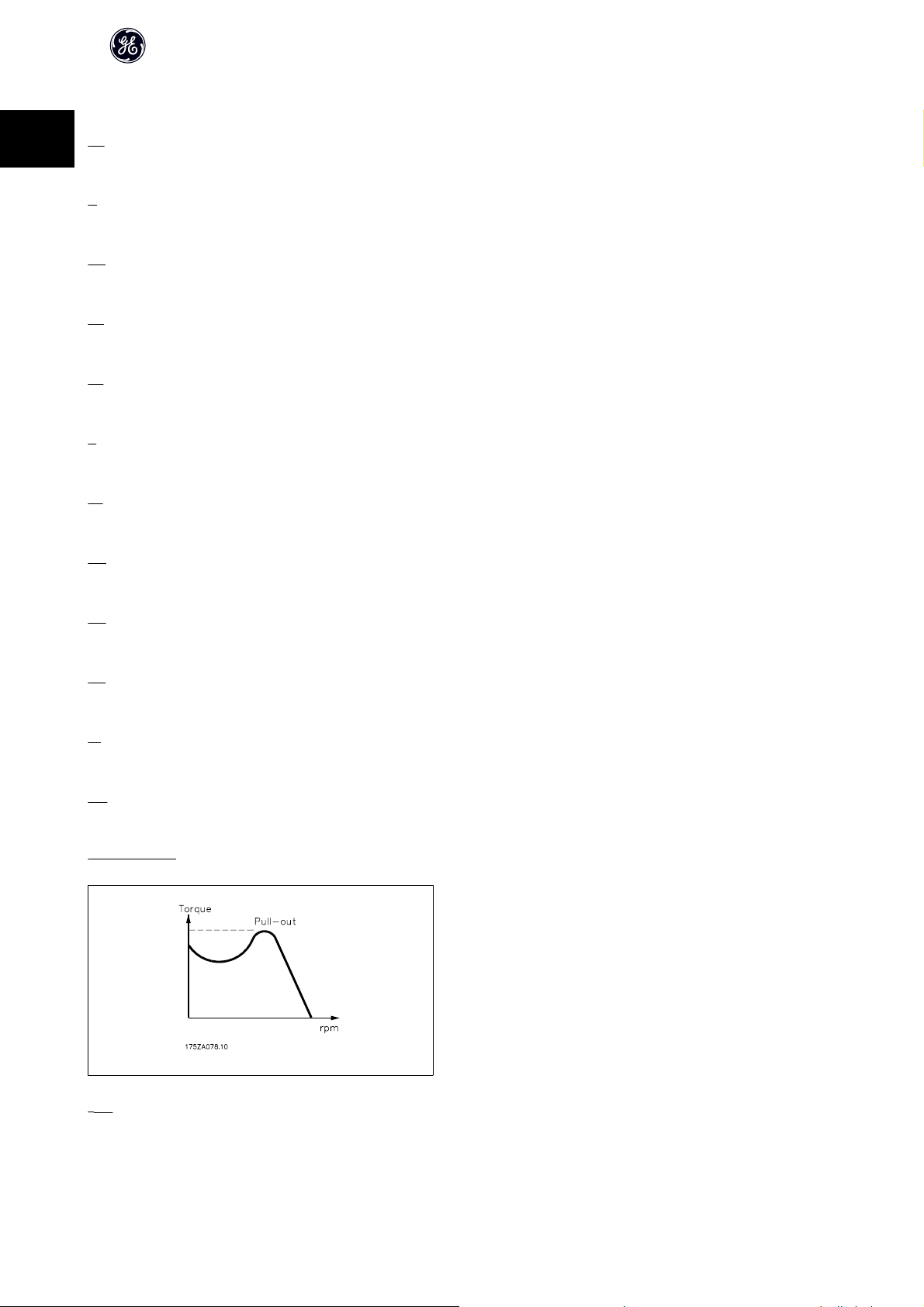
2.7 Advantages
2.7.1 Why use a Frequency Converter for Controlling Fans and Pumps?
A frequency converter takes advantage of the fact that centrifugal fans and pumps follow the laws of proportionality for such fans and pumps. For further
information see the text The Laws of Proportionality.
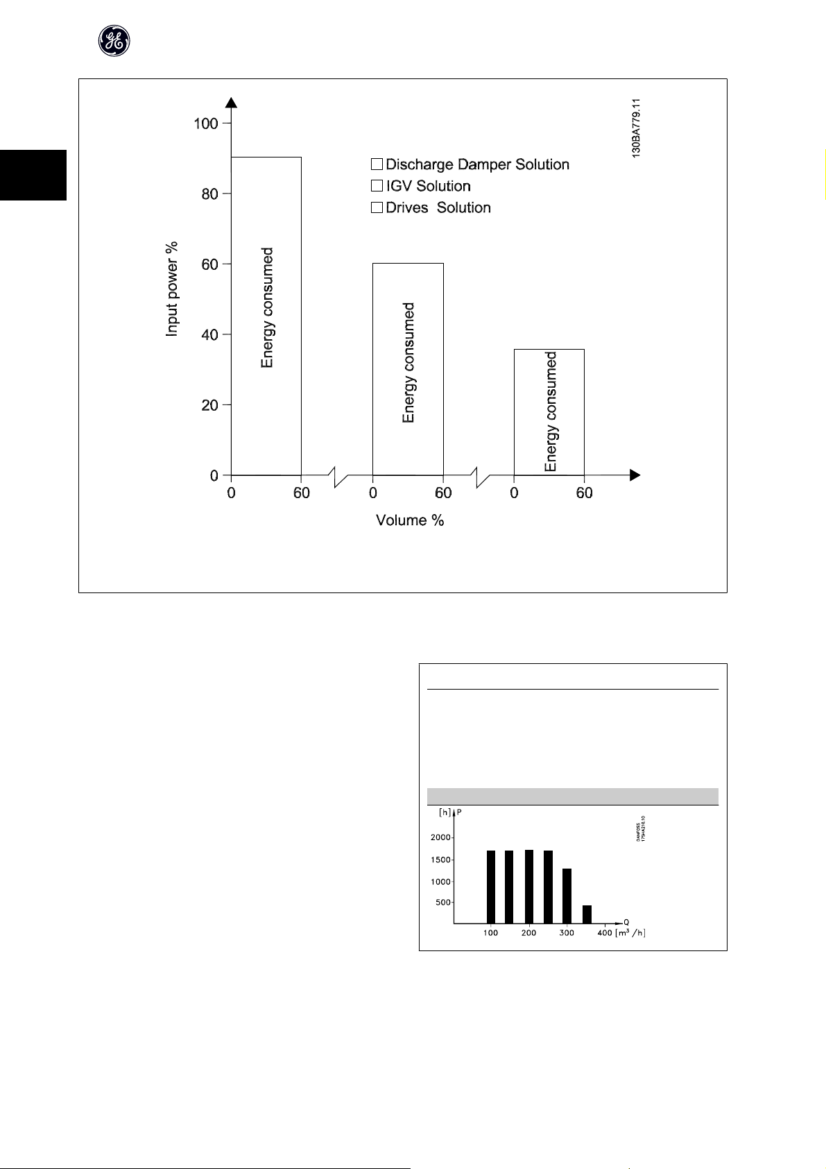
2.7.2 The Clear Advantage - Energy Savings
The very clear advantage of using a frequency converter for controlling the speed of fans or pumps lies in the electricity savings.
When comparing with alternative control systems and technologies, a frequency converter is the optimum energy control system for controlling fan and pump
systems.
Illustration 2.1: The graph is showing fan curves (A, B and C) for
reduced fan volumes.
15
2
AF-600 FP Design Guide
Illustration 2.2: When using a freq uency converter to reduce fan
capacity to 60% - more than 50% energy savings may be ob-
tained in typical applications.
2.7.3 Example of Energy Savings
As can be seen from the figure (the laws of proportionality), the flow is controlled by changing the RPM. By reducing the speed only 20% from the rated speed,
the flow is also reduced by 20%. This is because the flow is directly proportional to the RPM. The consumption of electricity, however, is reduced by 50%.
If the system in question only needs to be able to supply a flow that corresponds to 100% a few days in a year, while the average is below 80% of the rated flow
for the remainder of the year, the amount of energy saved is even more than 50%.
The laws of proportionality
The figure below describes the dependence of flow, pressure and power consumption on RPM.
Q = Flow P = Power
Q1 = Rated flow P1 = Rated power
= Reduced flow P2 = Reduced power
Q
2
H = Pressure n = Speed regulation
H1 = Rated pressure n1 = Rated speed
= Reduced pressure n2 = Reduced speed
H
2
16
Q
n
1
Flow
:
Pressure
Power
:
Q
:
2
P
P
=
H
H
1
2
1
2
=
1
n
2
=
n
(
n
n
2
1
(
)
n
2
3
1
)
2
2.7.4 Comparison of Energy Savings
The GE frequency converter solution offers major savings compared with
traditional energy saving solutions. This is because the frequency converter
is able to control fan speed according to thermal load on the system and the
fact that the frequency converter has a build-in facility that enables the fre-
quency converter to function as a Building Management System, BMS.
AF-600 FP Design Guide
2
The graph below illustrates typical energy savings obtainable with 3 well-
known solutions when fan volume is reduced to i.e. 60%.
As the graph shows, more than 50% energy savings can be achieved in typical
applications.
Illustration 2.3: The three common energy saving systems.
17
2
AF-600 FP Design Guide
Illustration 2.4: Discharge dampers reduce power consumption somewhat. Inlet Guide Vans offer a 40% reduction but are expensive to install. The
GEfrequency converter solution reduces energy consumption with more than 50% and is easy to install.
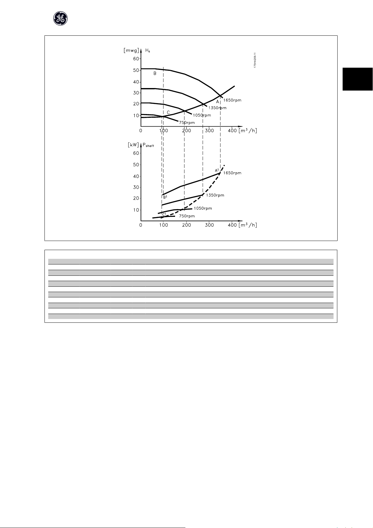
2.7.5 Example with Varying Flow over 1 Year
The example below is calculated on the basis of pump characteristics ob-
tained from a pump datasheet.
The result obtained shows energy savings in excess of 50% at the given flow
distribution over a year. The pay back period depends on the price per kwh
and price of frequency converter. In this example it is less than a year when
compared with valves and constant speed.
Energy savings
P
shaft=Pshaft output
Flow distribution over 1 year
18
AF-600 FP Design Guide
2
m3/h
Distribution Valve regulation Frequency converter control
% Hours Power Consumption Power Consumption
A1 - B
350 5 438 42,5 18.615 42,5 18.615
300 15 1314 38,5 50.589 29,0 38.106
250 20 1752 35,0 61.320 18,5 32.412
200 20 1752 31,5 55.188 11,5 20.148
150 20 1752 28,0 49.056 6,5 11.388
100 20 1752 23,0 40.296 3,5 6.132
Σ 100 8760 275.064 26.801
1
kWh A1 - C
1
kWh
2.7.6 Better Control
If a frequency converter is used for controlling the flow or pressure of a system, improved control is obtained.
A frequency converter can vary the speed of the fan or pump, thereby obtaining variable control of flow and pressure.
Furthermore, a frequency converter can quickly adapt the speed of the fan or pump to new flow or pressure conditions in the system.
Simple control of process (Flow, Level or Pressure) utilizing the built in PID control.
2.7.7 Cos φ Compensation
Generally speaking, a frequency converter with a cos of 1 provides power factor correction for the cos of the motor, which means that there is no need to
make allowance for the cos of the motor when sizing the power factor correction unit.
19
AF-600 FP Design Guide
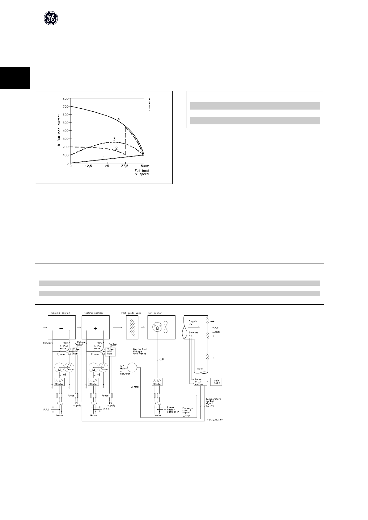
2.7.8 Star/Delta Starter or Soft-starter not Required
When larger motors are started, it is necessary in many countries to use equipment that limits the start-up current. In more traditional systems, a star/delta starter
or soft-starter is widely used. Such motor starters are not required if a frequency converter is used.
As illustrated in the figure below, a frequency converter does not consume more than rated current.
2
1 = AF-600 FP
2 = Star/delta starter
3 = Soft-starter
4 = Start directly on mains
2.7.9 Using a Frequency Converter Saves Money
The example on the following page shows that a lot of equipment is not required when a frequency converter is used. It is possible to calculate the cost of installing
the two different systems. In the example on the following page, the two systems can be established at roughly the same price.
2.7.10 Without a Frequency Converter
The figure shows a fan system made in the traditional way.
D.D.C. = Direct Digital Control E.M.S. = Energy Management system
V.A.V. = Variable Air Volume
Sensor P = Pressure Sensor T = Temperature
20

2.7.11 With a Frequency Converter
The figure shows a fan system controlled by frequency converters.
AF-600 FP Design Guide
2
21

AF-600 FP Design Guide
2.7.12 Application Examples
The next few pages give typical examples of applications within HVAC.
2.7.13 Variable Air Volume
2
VAV or Variable Air Volume systems, are used to control both the ventilation and temperature to satisfy the requirements of a building. Central VAV systems are
considered to be the most energy efficient method to air condition buildings. By designing central systems instead of distributed systems, a greater efficiency can
be obtained.
The efficiency comes from utilizing larger fans and larger chillers which have much higher efficiencies than small motors and distributed air-cooled chille rs. Savings
are also seen from the decreased maintenance requirements.
2.7.14 The AF-600 FP Solution
While dampers and IGVs work to maintain a constant pressure in the ductwork, a frequency converter solution saves much more energy and reduces the complexity
of the installation. Instead of creating an artificial pressure drop or causing a decrease in fan efficiency, the frequency converter decreases the speed of the fan
to provide the flow and pressure required by the system.
Centrifugal devices such as fans behave according to the centrifugal laws. This means the fans decrease the pressure and flow they produce as their speed is
reduced. Their power consumption is thereby significantly reduced.
The return fan is frequently controlled to maintain a fixed difference in airflow between the supply and return. The advanced PID controller of the HVAC frequency
converter can be used to eliminate the need for additional controllers.
Pressu re
Cooling coil
D1
D2
D3
Heating coil
Fil t e r
sig n al
Su pp l y f an
3
Ret ur n f a n
VAV b oxe s
Pressu re
transmitter
Flo w
Flo w
3
vav2.10
T
22

e
AF-600 FP Design Guide
2.7.15 Constant Air Volume
CAV, or Constant Air Volume systems are central ventilation systems usually used to supply large common zones with the minimum amounts of fresh tempered
air. They preceded VAV systems and therefore are found in older multi-zoned commercial buildings as well. These systems preheat amounts of fresh air utilizing
Air Handling Units (AHUs) with a heating coil, and many are also used to air condition buildings and have a cooling coil. Fan coil units are frequently used to assist
in the heating and cooling requirements in the individual zones.
2.7.16 The AF-600 FP Solution
With a frequency converter, significant energy savings can be obtained while maintaining decent control of the building. Temperature sensors or CO2 sensors
can be used as feedback signals to frequency converters. Whether controlling temperature, air quality, or both, a CAV system can be controlled to operate based
on actual building conditions. As the number of people in the controlled area decreases, the need for fresh air decreases. The CO
decreases the supply fans speed. The return fan modulates to maintain a static pressure setpoint or fixed difference between the supply and return air flows.
With temperature control, especially used in air conditioning systems, as the outside temperature varies as well as the number of people in the controlled zone
changes, different cooling requirements exist. As the temperature decreases below the set-point, the supply fan can decrease its speed. The return fan modulates
to maintain a static pressure set-point. By decreasing the air flow, energy used to heat or cool the fresh air is also reduced, adding further savings.
Several features of the GE dedicate d frequency converter can be utilized to improve the performance of your CAV system. One concern of controllin g a ventilation
system is poor air quality. The programmable minimum frequency can be set to maintain a minimum amount of supply air regardless of the feedback or reference
signal. The frequency converter also includes a 3-zone, 3 setpoint PID controller which allows monitoring both temperature and air quality. Even if the temperature
requirement is satisfied, the frequency converter will maintain enough supply air to satisfy the air quality sensor. The controller is capable of monitoring and
comparing two feedback signals to control the return fan by maintaining a fixed differential air flow between the supply and return ducts as well.
sensor detects lower levels and
2
2
Tem p er at u re
Cooling coil
D1
D2
D3
Heating coil
Fi lt er
sig n al
Su p pl y f an
Pressu r e
sig n al
Re t ur n f a n
Tem p er at u r
transmitter
Pressu r e
transmitter
23
AF-600 FP Design Guide
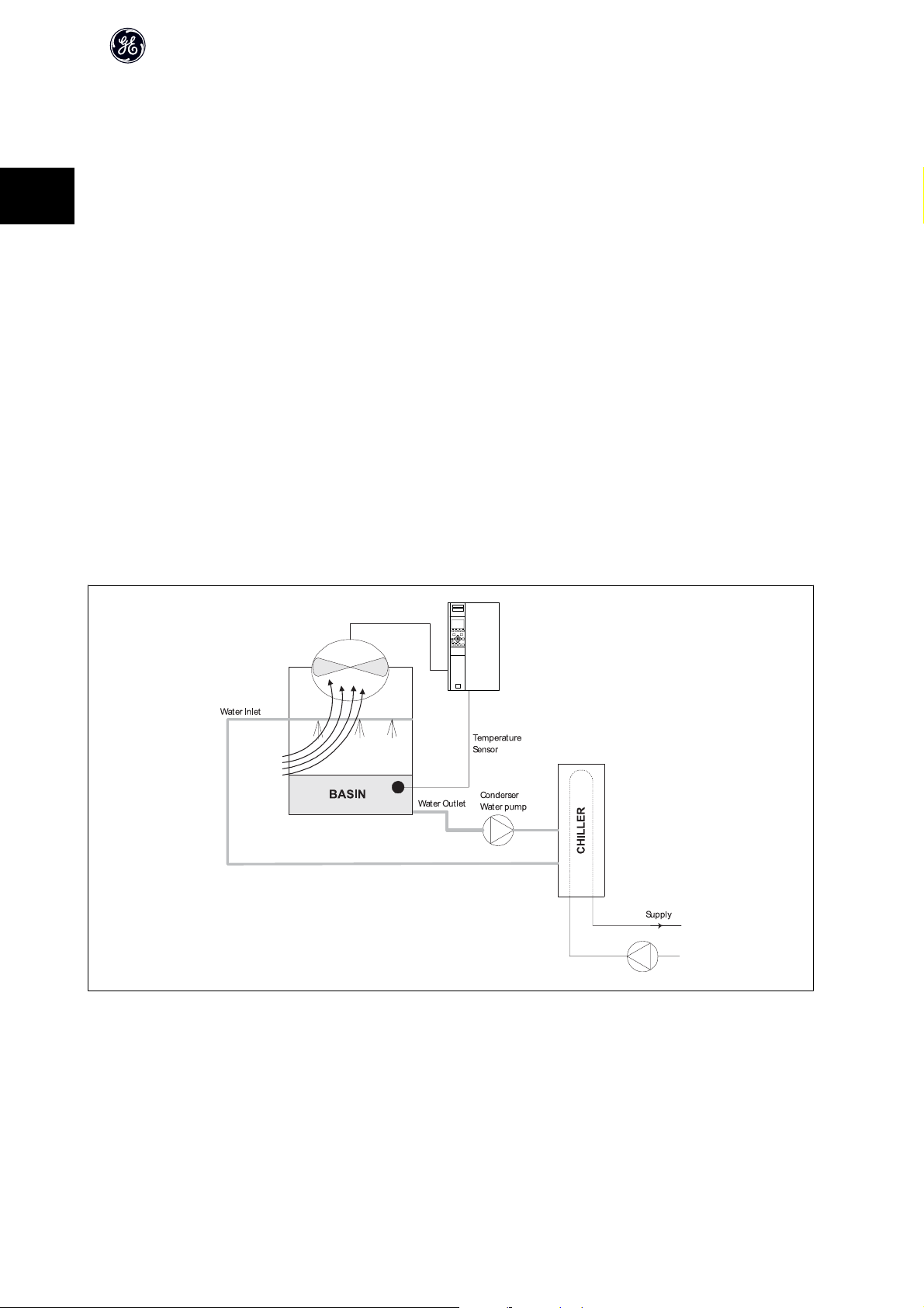
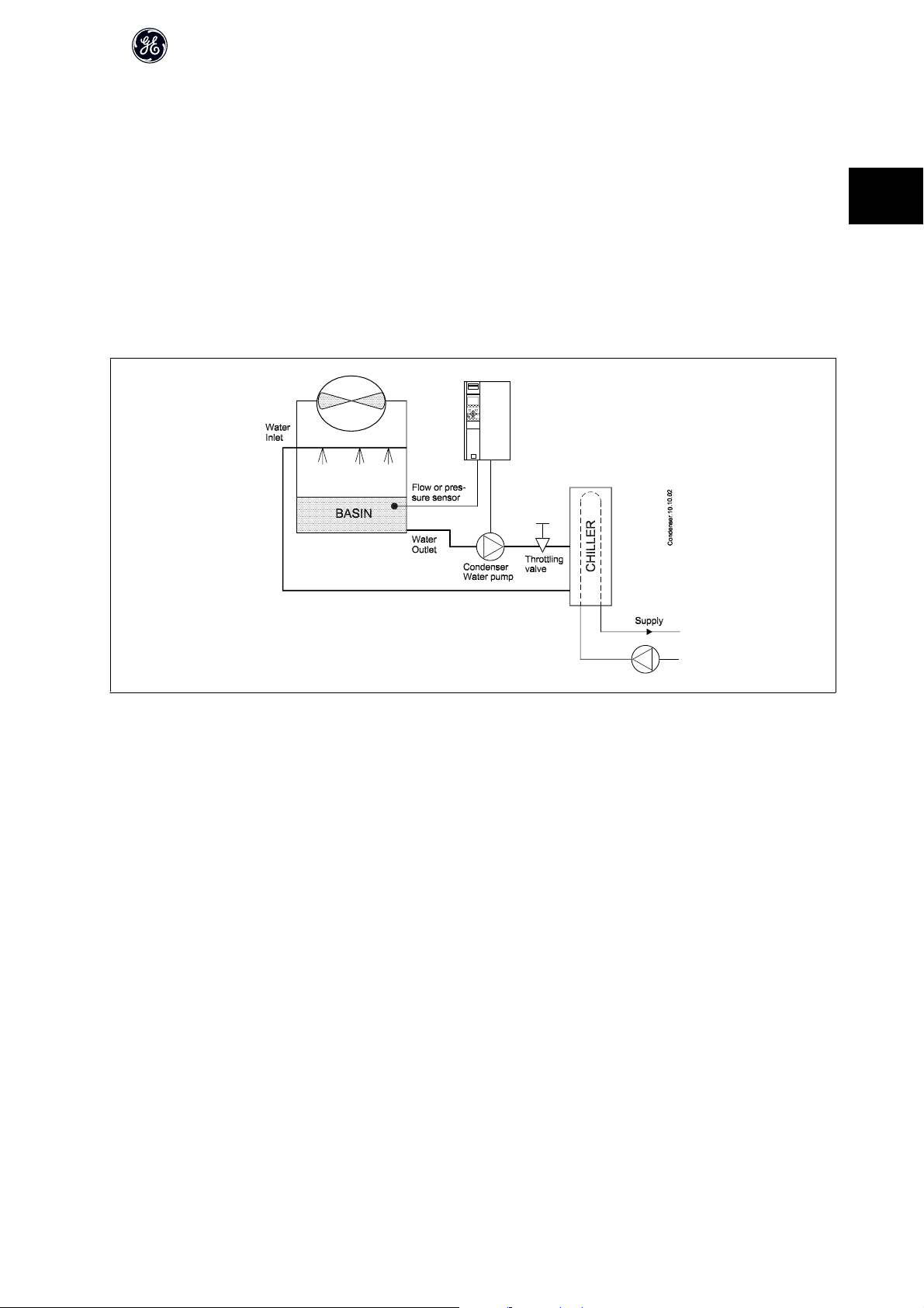
2.7.17 Cooling Tower Fan
Cooling Tower Fans are used to cool condenser water in water cooled chiller systems. Water cooled chillers provide the most efficient means of creating chilled
water. They are as much as 20% more efficient than air cooled chillers. Depending on climate, cooling towers are often the most energy efficient method of cooling
the condenser water from chillers.
They cool the condenser water by evaporation.
2
The condenser water is sprayed into the cooling tower onto the cooling towers “fill” to increase its surface area. The tower fan blows air through the fill and sprayed
water to aid in the evaporation. Evaporation removes energy from the water dropping its temperature. The cooled water collects in the cooling towers basin
where it is pumped back into the chillers condenser and the cycle is repeated.
2.7.18 The AF-600 FP solution
With a frequency converter, the cooling towers fans can be controlled to the required speed to maintain the condenser water temperature. The frequency
converters can also be used to turn the fan on and off as needed.
Several features of the GE dedicated frequency converter, the HVAC frequency converter can be utilized to improve the performance of your cooling tower fans
application. As the cooling tower fans drop below a certain speed, the effect the fan has on cooling the water becomes small. Also, when utilizing a gear-box to
frequency control the tower fan, a minimum speed of 40-50% may be required.
The customer programmabl e minimum frequency setting is available to main tain this minimum frequency even as the feedback or speed reference calls for lower
speeds.
Also as a standard feature, you can program the frequency converter to enter a “sleep” mode and stop the fan until a higher speed is required. Additionally, some
cooling tower fans have undesireable frequencies that may cause vibrations. These frequencies can easily be avoided by programming the bypass frequency
ranges in the frequency converter.
24
AF-600 FP Design Guide
2.7.19 Condenser Pumps
Condenser Water pumps are primarily used to circulate water through the condenser section of water cooled chillers and their associated cooling tower. The
condenser water absorbs the heat from the chiller's condenser section and releases it into the atmosphere in the cooling tower. These systems are used to provide
the most efficient means of creating chilled water, they are as much as 20% more efficient than air cooled chillers.
2.7.20 The AF-600 FP solution
Frequency converters can be added to condenser water pumps instead of balancing the pumps with a throttling valve or trimming the pump impeller.
Using a frequency converter instead of a throttling valve simply saves the energy that would have been absorbed by the valve. This can amount to savings of
15-20% or more. Trimming the pump impeller is irreversible, thus if the conditions change and higher flow is required the impeller must be replaced.
2
25
AF-600 FP Design Guide
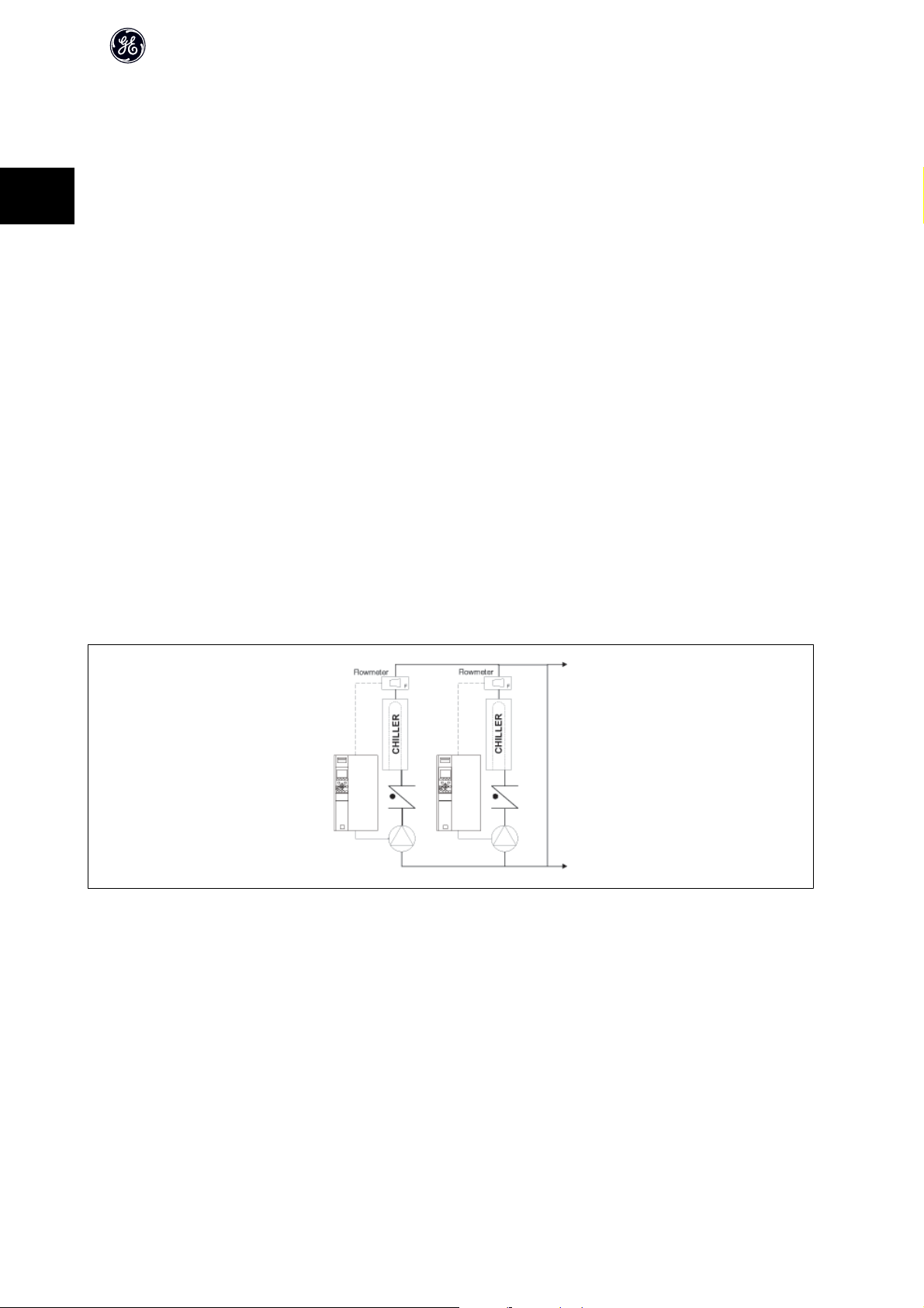
2.7.21 Primary Pumps
Primary pumps in a primary/secondary pumping system can be used to maintain a constant flow through devices that encounter operation or control difficulties
when exposed to variable flow. The primary/ secondary pumping technique decouples the “primary” production loop from the “secondary” distribution loop. This
allows devices such as chillers to obtain constant design flow and operate properly while allowing the rest of the system to vary in flow.
2
As the evaporator flow rate decreases in a chiller, the chilled water begins to become over-chilled. As this happens, the chiller attempts to decrease its cooling
capacity. If the flow rate drops far enough, or too quickly, the chiller cannot shed its load sufficiently and the chiller’s low evaporator temperature safety trips the
chiller requiring a manual reset. This situation is common in large installations especially when two or more chillers in parallel are installed if primary/ secondary
pumping is not utilized.
2.7.22 The AF-600 FP Solution
Depending on the size of the system and the size of the primary loop, the energy consumption of the primary loop can become substantial.
A frequency converter can be added to the primary system, to replace the throttling valve and/or trimming of the impellers, leading to reduced operating expenses.
Two control methods are common:
The first method uses a flow meter. Because the desired flow rate is known and is constant, a flow meter installed at the discharge of each chiller, can be used
to control the pump directly. Using the built-in PID controller, the frequency converter will always maintain the appropriate flow rate, even compensating for the
changing resistance in the primary piping loop as chillers and their pumps are staged on and off.
The other method is local speed determination. The operator simply decreases the output frequency until the design flow rate is achieved.
Using a frequency converter to decrease the pump speed is very similar to trimming the pump impelle r, except it doesn’t require any labor and the pump efficiency
remains higher. The balancing contractor simply decreases the speed of the pump until the proper flow rate is achieved and leaves the speed fixed. The pump
will operate at this speed any time the chiller is staged on. Because the primary loop doesn’t have control valves or oth er devices that can cause the system curve
to change and the variance due to staging pumps and chillers on and off is usually small, this fixed speed will remain appropriate. In the event the flow rate needs
to be increased later in the systems life, the frequency converter can simply increase the pump speed instead of requiring a new pump impeller.
26
AF-600 FP Design Guide
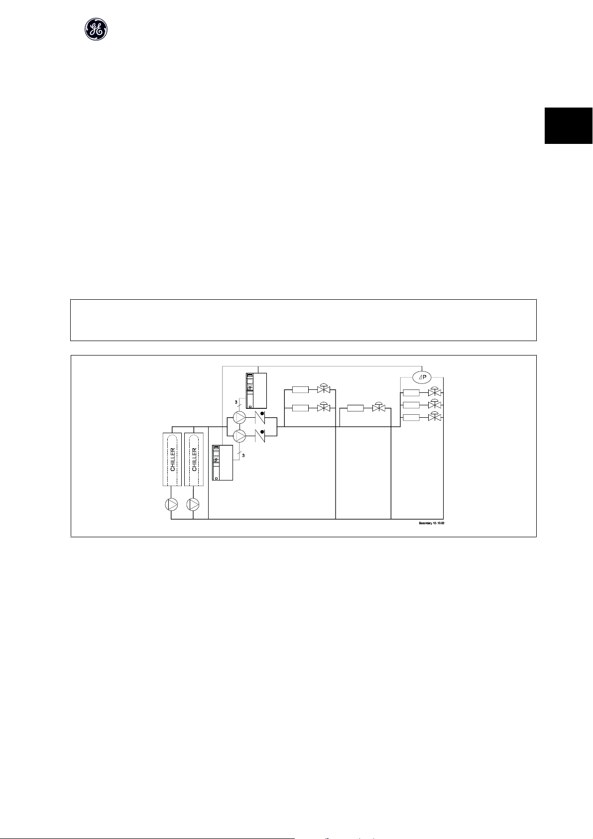
2.7.23 Secondary Pumps
Secondary pumps in a primary/secondary chilled water pumping system are used to distribute the chilled water to the loads from the primary production loop.
The primary/secondary pumping system is used to hydronically de-couple one piping loop from another. In this case. The primary pump is used to maintain a
constant flow through the chillers while allowing the secondary pumps to vary in flow, increase control and save energy.
If the primary/secondary design concept is not used and a variable volume system is designed, when the flow rate drops far enough or too quickly, the chiller
cannot shed its load properly. The chiller’s low evaporator temperature safety then trips the chiller requiring a manual reset. This situation is common in large
installations especially when two or more chillers in parallel are installed.
2.7.24 The AF-600 FP Solution
While the primary-secondary system with two-way valves improves energy savings and eases system control problems, the true energy savings and control
potential is realized by adding frequency converters.
With the proper sensor location, the addition of frequency converters allows the pumps to vary their speed to follow the system curve instead of the pump curve.
This results in the elimination of wasted energy and eliminates most of the over-pressurization, two-way valves can be subjected too.
As the monitored loads are reached, the two-way valves close down. This increases the differential pressure measured across the load and two-way valve. As
this differential pressure starts to rise, the pump is slowed to maintain the control head also called setpoint value. This set-point value is calculated by summing
the pressure drop of the load and two way valve together under design conditions.
NB!
Please note that when running multiple pumps in parallel, they must run at the same speed to maximize energy savings, either with individual dedicated drives
or one frequency converter running multiple pumps in parallel.
2
27

2.8 Control Structures
2.8.1 Control Principle
2
Illustration 2.5: Control structures.
AF-600 FP Design Guide
The frequency converter is a high performance unit for demanding applications. It can handle various kinds of motor control principles such as U/f special motor
mode and advanced vector control and can handle normal squirrel cage asynchronous motors.
Short circuit behavior on this drive depends on the 3 current transducers in the motor phases.
In par. H-40 Configuration Mode it can be selected if open or closed loop is to
be used
2.8.2 Control Structure Open Loop
Illustration 2.6: Open Loop structure.
In the configuration shown in the illustration above, par. H-40 Configuration Mode is set to Open loop [0]. The resulting reference from the reference handling
system or the local reference is received and fed through the ramp limitation and speed limitation before being sent to the motor control.
The output from the motor control is then limited by the maximum frequency limit.
28
AF-600 FP Design Guide
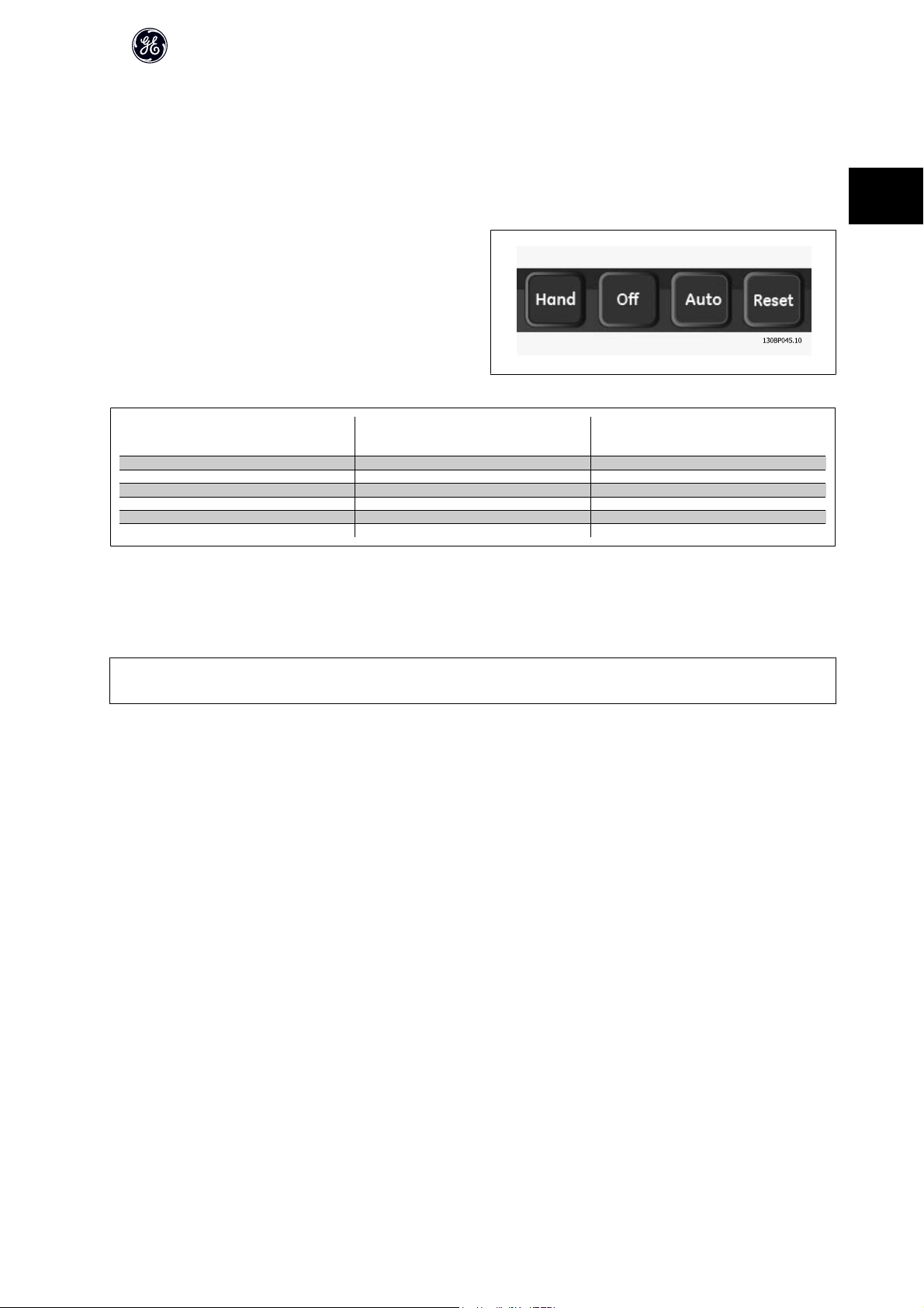
2.8.3 Local (Hand) and Remote (Auto) Control
The frequency converter can be operated manually via keypad or remotely via analog/digital inputs or serial bus.
If allowed in par. K-40 [Hand] Button on Keypad, par. K-41 [Off] Button on Keypad, par. K-42 [Auto] Button on Keypad, and par. K-43 [Reset] Button on Keypad, it is
possible to start and stop the frequency converter bykeypad using the [Hand] and [Off] keys. Alarms can be reset via the [RESET] key. After pressing the [Hand]
key, the frequency converter goes into Hand Mode and follows (as default) the Local reference set by using the keypad arrow keys up [
After pressing the [Auto] key, the frequency converter goes into Auto mode
and follows (as default) the Remote reference. In this mode, it is possible to
control the frequency converter via the digital inputs and various serial in-
terfaces (RS-485, USB, or an optional network). See more about starting,
stopping, changing ramps and parameter set-ups etc. par. group O-5# (serial
communication).
] and down [▼].
▲
2
Hand Off
Auto
keypad Keys
Hand Linked to Hand / Auto Local
Hand -> Off Linked to Hand / Auto Local
Auto Linked to Hand / Auto Remote
Auto -> Off Linked to Hand / Auto Remote
All keys Local Local
All keys Remote Remote
The table shows under which conditions either the Local Reference or the Remote Reference is active. One of them is always active, but both can not be active
at the same time.
Local reference will force the configuration mode to open loop, independent on the setting of par. H-40 Configuration Mode.
NB!
Local Reference will be restored at power-down.
Reference Site
par. F-02 Operation Method
Active Reference
2.8.4 Control Structure Closed Loop
The closed loop controller allows the drive to become an integral part of the controlled system. The drive receives a feedback signal from a sensor in the system.
It then compares this feedback to a set-point reference value and determines the error, if any, between these two signals. It then adjusts the speed of the motor
to correct this error.
For example, consider a pump application where the speed of a pump is to be controlled so that the static pressure in a pipe is constant. The desired static pressure
value is supplied to the drive as the set-point reference. A static pressure sensor measures the actual static pressure in the pipe and supplies this to the drive as
a feedback signal. If the feedback signal is greater than the set-point reference, the drive will slow down to reduce the pressure. In a similar way, if the pipe
pressure is lower than the set-point reference, the drive will automatically speed up to increase the pressure provided by the pump.
29

AF-600 FP Design Guide
2
NB!
While the default values for the drive’s Closed Loop controller will often provide satisfactory performance, the control of the system can often be optimized by
adjusting some of the Closed Loop controller’s parameters. It is also possible to autotune the PI constants.
The figure is a block diagram of the drive’s Closed Loop controller. The details of the Reference Handling block and Feedback Handling block are described in their
respective sections below.
2.8.5 Feedback Handling
A block diagram of how the drive processes the feedback signal is shown below.
Feedback handling can be configured to work with applications requiring advanced control, such as multiple setpoints and multiple feedbacks. Three types of
control are common.
Single Zone, Single Setpoint
Single Zone Single Setpoint is a basic configuration. Setpoint 1 is added to any other reference (if any, see Reference Handling) and the feedback signal is selected
using par. CL-20 Feedback Function.
Multi Zone, Single Setpoint
Multi Zone Single Setpoint uses two or three feedback sensors but only one setpoint. The feedbacks can be added, subtracted (only feedback 1 and 2) or averaged.
In addition, the maximum or minimum value may be used. Setpoint 1 is used exclusively in this configuration.
If Multi Setpoint Min [13] is selected, the setpoint/feedback pair with the largest difference controls the speed of the drive. Multi Setpoint Maximum [14] attempts
to keep all zones at or below their respective setpoints, while Multi Setpoint Min [13] attempts to keep all zones at or above their respective setpoints.
30

AF-600 FP Design Guide
Example:
A two zone two setpoint application Zone 1 setpoint is 15 bar and the feedback is 5.5 bar. Zone 2 setpoint is 4.4 bar and the feedback is 4.6 bar. If Multi Setpoint
Max [14] is selected, Zone 1’s setpoint and feedback are sent to the PID controller, since this has the smaller difference (feedback is higher than setpoint, resulting
in a negative difference). If Multi Setpoint Min [13] is selected, Zone 2’s setpoint and feedback is sent to the PID controller, since this has the larger difference
(feedback is lower than setpoint, resulting in a positive difference).
2.8.6 Feedback Conversion
In some applications it may be useful to convert the feedback signal. One example of this is using a pressure signal to provide flow feedback. Since the square
root of pressure is proportional to flow, the square root of the pressure signal yields a value proportional to the flow. This is shown below.
2
31

2.8.7 Reference Handling
Details for Open Loop and Closed Loop operation.
A block diagram of how the drive produces the Remote Reference is shown below:.
2
AF-600 FP Design Guide
32

AF-600 FP Design Guide
The Remote Reference is comprised of:
• Preset references.
• External references (analog inputs, pulse frequency inputs, digital potentiometer inputs and serial communication bus references).
• The Preset relative reference.
• Feedback controlled setpoint.
Up to 8 preset references can be programmed in the drive. The active preset reference can be selected using digital inputs or the serial communications bus. The
reference can also be supplied externally, most commonly from an analog input. This external source is selected by one of the 3 Reference Source parameters
(par. F-01 Frequency Setting 1, par. C-30 Frequency Command 2 and par. C-34 Frequency Command 3). Digipot is a digital potentiometer. This is also commonly
called a Speed Up/Speed Down Control or a Floating Point Control. To set it up, one digital input is programmed to increase the reference while another digital
input is programmed to decrease the reference. A third digital input can be used to reset the Digipot reference. All reference resources and the bus reference are
added to produce the total External Reference. The External Reference, the Preset Reference or the sum of the two can be selected to be the active reference.
Finally, this reference can by be scaled using par. F-64 Preset Relative Reference.
The scaled reference is calculated as follows:
Reference
Where X is the external reference, the preset reference or the sum of these and Y is par. F-64 Preset Relative Reference in [%].
NB!
If Y, par. F-64 Preset Relative Reference is set to 0%, the reference will not be affected by the scaling
= X + X ×
(
Y
100
)
2
2.8.8 Example of Closed Loop PID Control
The following is an example of a Closed Loop Control for a ventilation system:
In a ventilation system, the temperature is to be maintained at a constant value. The desired temperature is set between -5 and +35°C using a 0-10 volt poten-
tiometer. Because this is a cooling application, if the temperature is above the set-point value, the speed of the fan must be increased to provide more cooling
air flow. The temperature sensor has a range of -10 to +40°C and uses a two-wire transmitter to provide a 4-20 mA signal. The output frequency range of the
frequency converter is 10 to 50 Hz.
33

2
AF-600 FP Design Guide
1. Start/Stop via switch connected between terminals 12 (+24 V) and 18.
2. Temperature reference via a potentiometer (-5 to +35°C, 0 10 V) connected
to terminals 50 (+10 V), 53 (input) and 55 (common).
3. Temperature feedback via transmitter (-10-40°C, 4-20 mA) connected to
terminal 54. Switch S202 behind the keypad set to ON (current input).
2.8.9 Programming Order
Function Par. no. Setting
1) Make sure the motor runs properly. Do the following:
Set the motor parameters using nameplate data.
Run Auto Tune. P-04 Enable complete Auto Tune [1] and then run the Auto Tune
2) Check that the motor is running in the right direction.
Run Motor Rotation Check. P-08 If the motor runs in the wrong direction, remove power tem-
3) Make sure the frequency converter limits are set to safe values
Check that the ramp settings are within capabilities of the drive
and allowed application operating specifications.
Prohibit the motor from reversing (if necessary) H-08 Clockwise [0]
Set acceptable limits for the motor speed. F-16
Switch from open loop to closed loop. H-40 Closed Loop [3]
4) Configure the feedback to the PID controller.
Select the appropriate reference/feedback unit.
5) Configure the set-point reference for the PID controller.
Set acceptable limits for the set-point reference.
Choose current or voltage by switches S201 / S202
6) Scale the analog inputs used for set-point reference and feedback.
Scale Analog Input 53 for the pressure range of the potentiometer (0 - 10 Bar, 0 - 10 V).
Scale Analog Input 54 for pressure sensor (0 - 10 Bar, 4 - 20 mA) AN-22
7) Tune the PID controller parameters.
Adjust the drive’s Closed Loop Controller, if needed.
8) Finished!
Save the parameter setting to the keypad for safe keeping
P-0# & F-04, F-05 As specified by motor name plate
function.
porarily and reverse two of the motor phases.
F-07
F-08
F-15
F-03
CL-12 Bar [71]
CL-13
CL-14
AN-10
AN-11
AN-14
AN-15
AN-23
AN-24
AN-25
CL-93
CL-94
K-50 All to keypad [1]
60 sec.
60 sec.
Depends on motor/load size!
Also active in Hand mode.
10 Hz, Motor min speed
50 Hz, Motor max speed
50 Hz, Drive max output frequency
0 Bar
10 Bar
0 V
10 V (default)
0 Bar
10 Bar
4 mA
20 mA (default)
0 Bar
10 Bar
See Optimization of the PID Controller, below.
34

AF-600 FP Design Guide
2.8.10 Tuning the Drive Closed Loop Controller
Once the drive’s Closed Loop Controller has been set up, the performance of the controller should be tested. In many cases, its performance may be acceptable
using the default values of par. CL-93 PID Proportional Gain and par. CL-94 PID Integral Time. However, in some cases it may be helpful to optimize these parameter
values to provide faster system response while still controlling speed overshoot.
2.8.11 Manual PID Adjustment
1. Start the motor
2. Set par. CL-93 PID Proportional Gain to 0.3 and increase it until the feedback signal begins to oscillate. If necessary, start and stop the drive or make
step changes in the set-point reference to attempt to cause oscillation. Next reduce the PID Proportional Gain until the feedback signal stabilizes. Then
reduce the proportional gain by 40-60%.
3. Set par. CL-94 PID Integral Time to 20 sec. and reduce it until the feedback signal begins to oscillate. If necessary, start and stop the drive or make step
changes in the set-point reference to attempt to cause oscillation. Next, increase the PID Integral Time until the feedback signal stabilizes. Then increase
of the Integral Time by 15-50%.
4. par. CL-95 PID Differentiation Time should only be used for very fast-acting systems. The typical value is 25% of par. CL-94 PID Integral Time. The differential
function should only be used when the setting of the proportional gain and the integral time has been fully optimized. Make sure that oscillations of the
feedback signal are sufficiently dampened by the low-pass filter for the feedback signal (par. AN-16, AN-26, E-64 or E-69 as required).
2.9 General Aspects of EMC
2
2.9.1 General Aspects of EMC Emissions
Electrical interference is usually conducted at frequences in the range 150 kHz to 30 MHz. Airborne interference from the drive system in the range 30 MHz to 1
GHz is generated from the inverter, motor cable, and the motor.
As shown in the illustration below, capacitive currents in the motor cable coupled with a high dV/dt from the motor voltage generate leakage currents.
The use of a screened motor cable increases the leakage current (see illustration below) because screened cables have higher capacitance to earth than
unscreened cables. If the leakage current is not filtered, it will cause greater interference on the mains in the radio frequency range below approximately 5 MHz.
Since the leakage current (I
motor cable according to the below figure.
The screen reduces the radiated interference but increases the low-frequency interference on the mains. The motor cable screen must be connected to the
frequency converter enclosure a s well as on the motor enclosure. This is best done by using integrated screen clamps so as to avoid twisted screen ends (pigtails).
These increase the screen impedance at higher frequencies, which reduces the screen effect and increases the leakage current (I
If a screened cable is used for networknetwork, relay, control cable, signal interface and brake, the screen must be mounted on the enclosure at both ends. In
some situations, however, it will be necessary to break the screen to avoid current loops.
) is carried back to the unit through the screen (I 3), there will in principle only be a small electro-magnetic field (I4) from the screened
1
).
4
If the screen is to be placed on a mounting plate for the frequency converter, the mounting plate must be made of metal, because the screen currents have to
be conveyed back to the unit. Moreover, ensure good electrical contact from the mounting plate through the mounting screws to the frequency converter chassis.
35

AF-600 FP Design Guide
NB!
When unscreened cables are used, some emission requirements are not complied with, although the immunity requirements are observed.
In order to reduce the interference level from the entire system (unit + installation), make motor and brake cables as short as possible. Avoid placing cables with
a sensitive signal level alongside motor and brake cables. Radio interference higher than 50 MHz (airborne) is especially generated by the control electronics.
2
2.9.2 Emission Requirements
According to the EMC product standard for adjustable speed frequency converters EN/IEC61800-3:2004 the EMC requirements depend on the intended use of
the frequency converter. Four ca tegories are defined in the EMC product standard. The definitions of the four categories together with the requirements for mains
supply voltage conducted emissions are given in the table below:
Category
C1 frequency converters installed in the first environment (home and office) with a supply voltage
C2 frequency converters installed in the first environment (home and office) with a supply voltage
C3 frequency converters installed in the second environment (industrial) with a supply voltage
C4 frequency converters installed in the second environment with a supply voltage equal to or
When the generic emission standards are used the frequency converters are required to comply with the following limits:
Environment
First environment
(home and office)
Second environment
(industrial environment)
Definition
less than 1000 V.
less than 1000 V, which are neither plug-in nor movable and are intended to be installed and
commissioned by a professional.
lower than 1000 V.
above 1000 V or rated current equal to or above 400 A or intended for use in complex systems.
Generic standard
EN/IEC61000-6-3 Emission standard for residential, commercial and
light industrial environments.
EN/IEC61000-6-4 Emission standard for industrial environments. Class A Group 1
Conducted emission requirement accord-
ing to the limits given in EN55011
Conducted emission requirement accord-
ing to the limits given in EN55011
2.9.3 EMC Test Results (Emission)
Class B
Class A Group 1
Class A Group 2
No limit line.
An EMC plan should be made.
Class B
The following test results have been obtained using a system with a frequency converter (with options if relevant), a screened control cable, a control box
with potentiometer, as well as a motor and motor screened cable.
RFI filter type Conducted emission.
Standard EN 55011 Class A2 EN 55011 Class A1 EN 55011 Class B EN 55011 Class A1 EN 55011 Class B
A1/B1 RFI Filter installed
0.75-45 kW 200-240 V
0.75-90 kW 380-480 V 150 m 150 m 50 m Yes No
No A1/B1 RFI Filter installed
0.75-3.7 kW 200-240 V
5.5-45 kW 200-240 V 25 m No No No No
0.75-7.5 kW 380-480 V
11-90 kW 380-480 V
110-1000 kW 380-480 V
110-1200 kW 525-690 V
No A1/B1 RFI Filter installed
0.75-90 kW 525-600 V
Table 2.1: EMC Test Results (Emission)
Maximum shielded cable length.
Industrial environment Housing, trades and
light industries
150 m 150 m 50 m Yes No
5 m No No No No
5 m No No No No
25 m No No No No
150 m No No No No
150 m No No No No
- - - - -
Industrial environment Housing, trades and light in-
Radiated emission
dustries
36

2.9.4 General Aspects of Harmonics Emission
AF-600 FP Design Guide
A frequency converter takes up a non-sinusoidal current from mains, which
increases the input current I
means of a Fourier analysis and split up into sine-wave currents with different
frequencies, i.e. different harmonic currents I
quency:
The harmonics do not affect the power co nsumption directly but increase the
heat losses in the installation (transformer, cables). Consequently, in plants
with a high percentage of rectifier load, maintain harmonic currents at a low
level to avoid overload of the transformer and high temperature in the cables.
NB!
Some of the harmonic currents might disturb communication equipment connected to the same transformer or cause resonance in connection with power-
factor correction batteries.
NB!
To ensure low harmonic currents, the frequency converter is equipped with intermediate circuit coils as standard. This normally reduces the input current I
by 40%.
RMS
The voltage distortion on the mains supply voltage depends on the size of the harmonic currents multiplied by the mains impedance for the frequency in question.
The total voltage distortion THD is calculated on the basis of the individual voltage harmonics using this formula:
. A non-sinusoidal current is transformed by
RMS
with 50 Hz as the basic fre-
N
Harmonic currents I
1
I
5
I
7
Hz 50 Hz 250 Hz 350 Hz
2
THD
%=
2
2
+
U
5
+ ... +
U
7
2
U
N
(UN% of U)
2.9.5 Harmonics Emission Requirements
Equipment connected to the public supply network:
Options: Definition:
1 IEC/EN 61000-3-2 Class A for 3-phase balanced equip-
ment (for professional equipment only up to 1 kW total
power).
2 IEC/EN 61000-3-12 Equipment 16A-75A and professional
equipment as from 1 kW up to 16A phase current.
2.9.6 Harmonics Test Results (Emission)
Power sizes from 0.75 kW and up to 18.5 kW in 200 V and up to 90 kW in 460 V complies with IEC/EN 61000-3-12, Table 4. Power sizes 110 - 450 kW in 460 V also
complies with IEC/EN 61000-3-12 even though not required because currents are above 75 A.
Provided that the short-circuit power of the supply S
S
= 3 ×
SC
at the interface point between the user’s supply and the public system (R
R
SCE
×
U
×
mains
I
equ
is greater than or equal to:
sc
= 3 × 120 × 400 ×
I
equ
).
sce
It is the responsibility of the installer or user of the equipment to ensure, by consultation with the distribution network operator if necessary, that the equipment
is connected only to a supply with a short-circuit power S
Other power sizes can be connected to the public supply network by consultation with the distribution network operator.
greater than or equal to specified above.
sc
37

AF-600 FP Design Guide
Compliance with various system level guidelines:
The harmonic current data in the table are given in accordance with IEC/EN61000-3-12 with reference to the Power Drive Systems product standard. They may
be used as the basis for calculation of the harmonic currents' influence on the power supply system and for the documentation of compliance with relevant
regional guidelines: IEEE 519 -1992; G5/4.
2
2.9.7 Immunity Requirements
The immunity requirements for frequency converters depend on the environment where they are installed. The requirements for the industrial environment are
higher than the requirements for the home and office environment. All GE frequency converters comply with the requirements for the industrial environment and
consequently comply also with the lower requirements for home and office environment with a large safety margin.
In order to document immunity against electrical interference from electrical phenomena, the following immunity tests have been made on a system consisting
of a frequency converter (with options if relevant), a screened control cable and a control box with potentiometer, motor cable and motor.
The tests were performed in accordance with the following basic standards:
• EN 61000-4-2 (IEC 61000-4-2): Electrostatic discharges (ESD): Simulation of electrostatic discharges from human beings.
• EN 61000-4-3 (IEC 61000-4-3): Incoming electromagnetic field radiation, amplitude modulated simulation of the effects of radar and radio communi-
cation equipment as well as mobile communications equipment.
• EN 61000-4-4 (IEC 61000-4-4): Burst transients: Simulation of interference brought about by switching a contactor, relay or similar devices.
• EN 61000-4-5 (IEC 61000-4-5): Surge transients: Simulation of transients brought about e.g. by lightning that strikes near installations.
• EN 61000-4-6 (IEC 61000-4-6): RF Common mode: Simulation of the effect from radio-transmission equipment joined by connection cables.
See following EMC immunity form.
Voltage range: 200-240 V, 380-480 V
Basic standard Burst
IEC 61000-4-4
Surge
IEC 61000-4-5
ESD
IEC 61000-4-2
Radiated electromagnetic field
IEC 61000-4-3
RF common
mode voltage
IEC 61000-4-6
Acceptance criterion B B B A A
Line
Motor
4 kV CM
4 kV CM
Brake 4 kV CM
Load sharing 4 kV CM
Control wires
2 kV CM
Standard bus 2 kV CM
Relay wires 2 kV CM
Application and network options 2 kV CM
keypad cable
External 24 V DC
Enclosure
2 kV CM
2 kV CM
— —
2 kV/2 DM
4 kV/12 CM
4 kV/2
4 kV/2
4 kV/2
2 kV/2
2 kV/2
2 kV/2
2 kV/2
2 kV/2
0.5 kV/2 DM
1 kV/12 CM
— —
1)
1)
1)
1)
1)
1)
1)
1)
— —
— —
— — 10 V
— —
— —
— —
— —
— — 10 V
— —
8 kV AD
6 kV CD
10 V/m —
AD: Air Discharge
CD: Contact Discharge
CM: Common mode
DM: Differential mode
1. Injection on cable shield.
Table 2.2: Immunity
10 V
10 V
10 V
10 V
10 V
10 V
10 V
10 V
RMS
RMS
RMS
RMS
RMS
RMS
RMS
RMS
RMS
RMS
38

2.10 Galvanic Isolation (PELV)
2.10.1 PELV - Protective Extra Low Voltage
AF-600 FP Design Guide
PELV offers protection by way of extra low voltage. Protection against electric shock is ensured when the electrical supply is of the PELV type and the installation
is made as described in local/national regulations on PELV supplies.
All control terminals and relay terminals 01-03/04-06 comply with PELV (Protective Extra Low Voltage) (Does not apply to grounded Delta leg above 400 V).
Galvanic (ensured) isolation is obtained by fulfilling requirements for higher isolation and by providing the relevant creapage/clearance distances. These require-
ments are described in the EN 61800-5-1 standard.
The components that make up the electrical isolation, as described below, also comply with the requirements for higher isolation and the relevant test as described
in EN 61800-5-1.
The PELV galvanic isolation can be shown in six locations (see illustration):
In order to maintain PELV all connections made to the control terminals must be PELV, e.g. thermistor must be reinforced/double insulated.
1. Power supply (SMPS) incl. signal isolation of U
termediate current voltage.
2. Gate drive that runs the IGBTs (trigger transformers/opto-couplers).
3. Current transducers.
4. Opto-coupler, brake module.
5. Internal inrush, RFI, and temperature measurement circuits.
6. Custom relays.
, indicating the in-
DC
2
Illustration 2.7: Galvanic isolation
The functional galvanic isolation (a and b on drawing) is for the 24 V back-up option and for the RS 485 standard bus interface.
Installation at high altitude:
380 - 480 V, unit size 1x, 2x and 3x: At altitudes above 2 km, please contact GE regarding PELV.
380 - 480V, unit size 4x, 5x and 6x: At altitudes above 3 km, please contact GE regarding PELV.
525 - 690 V: At altitudes above 2 km, please contact GE regarding PELV.
39

2.11 Earth Leakage Current
Warning:
Touching the electrical ts may be fatal - even after the equipment has been disconnected from mains.
2
Also make sure that other voltage inputs have been disconnected, such as load sharing (linkage of DC intermediate circuit), as well as the
motor connection for kinetic back-up.
Before touching any electrical parts, wait at least the amount of time indicated in the Safety Precautions section.
Shorter time is allowed only if indicated on the nameplate for the specific unit.
Leakage Current
The earth leakage current from the frequency converter exceeds 3.5 mA. To ensure that the earth cable has a good mechanical connection
to the earth connection (terminal 95), the cable cross section must be at least 10 mm
Residual Current Device
This product can cause a d.c. current in the protective conductor. Where a residual current device (RCD) is used for protection in case of direct
or indirect contact, only an RCD of Type B is allowed on the supply side of this product. Otherwise, another protective measure shall be applied,
such as separation from the environment by double or reinforced insulation, or isolation from the supply system by a transformer.
Protective earthing of the frequency converter and the use of RCD's must always follow national and local regulations.
2.13 Extreme Running Conditions
AF-600 FP Design Guide
2
or 2 rated earth wires terminated seately.
Short Circuit (Motor Phase – Phase)
The frequency converter is protected against short circuits by means of current measurement in each of the three motor phases or in the DC link. A short circuit
between two output phases will cause an overcurrent in the inverter. The inverter will be turned off individually when the short circuit current exceeds the permitted
value (Alarm 16 Trip Lock).
To protect the frequency converter against a short circuit at the load sharing and brake outputs please see the design guidelines.
Switching on the Output
Switching on the output between the motor and the frequency converter is fully permitted. You cannot damage the frequency converter in any way by switching
on the output. However, fault messages may appear.
Motor-generated Over-voltage
The voltage in the intermediate circuit is increased when the motor acts as a generator. This occurs in following cases:
1. The load drives the motor (at constant output frequency from the frequency converter), ie. the load generates energy.
2. During deceleration if the moment of inertia is high, the friction is low and the decel time is too short for the energy to be dissipated as a loss in the
frequency converter, the motor and the installation.
3. Incorrect slip compensation setting may cause higher DC link voltage.
The control unit may attempt to correct the ramp if possible (par. B-17 Over-voltage Control.
The inverter turns off to protect the transistors and the intermediate circuit capacitors when a certain voltage level is reached.
See par. B-10 Brake Function and par. B-17 Over-voltage Control to select the method used for controlling the intermediate circuit voltage level.
Mains Drop-out
During a mains drop-out, the frequen cy converter keeps running until the intermediate circuit voltage drops below the minimum stop level, which is typically 15%
below the frequency converter's lowest rated supply voltage. The mains voltage before the drop-out and the motor load determines how long it takes for the
inverter to coast.
Static Overload in Advanced Vector Control mode
When the frequency converter is overloaded (the torque limit in par. F-40 Torque Limiter (Driving)/par. F-41 Torque Limiter (Braking) is reached), the controls reduces
the output frequency to reduce the load.
If the overload is excessive, a current may occur that makes the frequency converter cut out after approx. 5-10 s.
Operation within the torque limit is limited in time (0-60 s) in par. SP-25 Trip Delay at Torque Limit.
40

AF-600 FP Design Guide
2.13.1 Motor Thermal Protection
This is the way GE is protecting the motor from being overheated. It is an electronic feature that simulates a bimetal relay based on internal measurements. The
characteristic is shown in the following figure:
2
Illustration 2.8: The X-axis is showing the ratio between I
Thermal Overload cuts off and trips the drive. The curves are showing the characteristic nominal speed at twice the nominal speed and at 0,2x the
nominal speed.
It is clear that at lower speed the Electronic Thermal Overload cuts of at lower heat due to less cooling of the motor. In that way the motor are protected from
being over heated even at low speed. The Electronic Thermal Overload feature is calculating the motor temperature based on actual current and speed. The
calculated temperature is visible as a read out parameter in par. DR-18 Motor Thermal in the frequency converter.
motor
and I
nominal. The Y-axis is showing the time in seconds before the Electronic
motor
41

The thermistor cut-out value is > 3 kΩ.
Integrate a thermistor (PTC sensor) in the motor for winding protection.
Motor protection can be implemented using a range of techniques: PTC sen-
sor in motor windings; mechanical thermal switch (Klixon type); or Electronic
2
Thermal Electronic Thermal Overload.
Using a digital input and 24 V as power supply:
Example: The frequency converter trips when the motor temperature is too
high.
Parameter set-up:
Set par. F-10 Electronic Overload to Thermistor Trip [2]
Set par. F-12 Motor Thermistor Input to Digital Input 33 [6]
AF-600 FP Design Guide
Using a digital input and 10 V as power supply:
Example: The frequency converter trips when the motor temperature is too
high.
Parameter set-up:
Set par. F-10 Electronic Overload to Thermistor Trip [2]
Set par. F-12 Motor Thermistor Input to Digital Input 33 [6]
Using an analog input and 10 V as power supply:
Example: The frequency converter trips when the motor temperature is too
high.
Parameter set-up:
Set par. F-10 Electronic Overload to Thermistor Trip [2]
Set par. F-12 Motor Thermistor Input to Analog Input 54 [2]
Do not select a reference source.
Input
Digital/analog
Digital 24 V
Digital 10 V
Analog 10 V
Supply Voltage
Volt
Threshold
Cut-out Values
< 6.6 kΩ - > 10.8 kΩ
< 800Ω - > 2.7 kΩ
< 3.0 kΩ - > 3.0 kΩ
42

AF-600 FP Design Guide
NB!
Check that the chosen supply voltage follows the specification of the used thermistor element.
Summary
With the Torque limit feature the motor is protected for being overloaded independent of the speed. With the Electronic Thermal Overload the motor is protected
for being over heated and there is no need for any further motor protection. That means when the motor is heated up the Electronic Thermal Overload timer
controls for how long time the motor can be running at the high temperature before it is stopped in order to prevent over heating. If the motor is overloaded
without reaching the temperature where the Electronic Thermal Overload shuts of the motor, the torque limit is protecting the motor and application for being
overloaded.
NB!
Electronic Thermal Overload is activated in par. F-10 Electronic Overload and is controlled in par. F-40 Torque Limiter (Driving). The time before the torque limit
warning trips the frequency converter is set in par. SP-25 Trip Delay at Torque Limit.
2
43

3
AF-600 FP Design Guide
44

3 AF-600 FP Selection
3.1 Options and Accessories
GE offers a wide range of options and accessories for the frequency converters.
AF-600 FP Design Guide
3.1.1 Mounting of Option Modules in Slot B
The power to the frequency converter must be disconnected.
For unit sizes 12 and 13:
• Remove the keypad , the terminal cover, and the keypad frame from the frequency converter.
• Fit the option card into slot B.
• Connect the control cables and relieve the cable by the enclosed cable strips.
Remove the knock out in the extended keypad frame delivered in the option set, so that the option will fit under the extended keypad frame.
• Fit the extended keypad frame and terminal cover.
• Fit the keypad or blind cover in the extended keypad frame.
• Connect power to the frequency converter.
• Set up the input/output functions in the corresponding parameters, as mentioned in the section General Technical Data.
For unit sizes 21, 22, 31 and 32:
• Remove the keypad and the keypad cradle
• Fit the option card into slot B
• Connect the control cables and relieve the cable by the enclosed cable strips
• Fit the cradle
• Fit the keypad
3
Unit sizes 12, 13 and 23 Unit sizes 15, 21, 22, 24, 31, 32, 33 and 34
45

AF-600 FP Design Guide
3.1.2 General Purpose Input Output Module OPCGPIO
OPCGPIO General Purpose I/O Option Module is used for extension of the
number of digital and analog inputs and outputs of the frequency converter.
Contents: OPCGPIO must be fitted into slot B in the frequency converter.
• OPCGPIO option module
• Extended keypad frame
3
•Terminal cover
Galvanic Isolation in the OPCGPIO
Digital/analog inputs are galvanically isolated from other inputs/outputs on the OPCGPIO and in the control card of the frequency converter. Digital/analog outputs
in the OPCGPIO are galvanically isolated from other inputs/outputs on the OPCGPIO, but not from these on the control card of the frequency converter.
If the digital inputs 7, 8 or 9 are to be switched by use of the internal 24 V power supply (terminal 9) the connection between terminal 1 and 5 which is illustrated
in the drawing has to be established.
Illustration 3.1: Principle Diagram
46

AF-600 FP Design Guide
3.1.3 Digital Inputs - Terminal X30/1-4
Parameters for set-up: E-53, E-54 and E-55
Number of digital
inputs
3 0-24 V DC PNP type:
3.1.4 Analog Voltage Inputs - Terminal X30/10-12
Parameters for set-up: AN-3#, AN-4# and DR-76
Number of analog voltage inputs Standardized input signal Tolerance Resolution Max. Input impedance
2 0-10 V DC ± 20 V continuously 10 bits Approx. 5 K ohm
Voltage level Voltage levels Tolerance Max. Input impedance
Common = 0 V
Logic “0”: Input < 5 V DC
Logic “0”: Input > 10 V DC
NPN type:
Common = 24 V
Logic “0”: Input > 19 V DC
Logic “0”: Input < 14 V DC
± 28 V continuous
± 37 V in minimum 10 sec.
Approx. 5 k ohm
3
3.1.5 Digital Outputs - Terminal X30/5-7
Parameters for set-up: E-56 and E-57
Number of digital outputs Output level Tolerance Max.impedance
2 0 or 24 V DC ± 4 V
≥ 600 ohm
3.1.6 Analog Outputs - Terminal X30/5-8
Parameters for set-up: AN-6# and DR-77
Number of analog outputs Output signal level Tolerance Max.impedance
1 0/4 - 20 mA ± 0.1 mA < 500 ohm
47

AF-600 FP Design Guide
3.1.7 OPCRLY Relay Option Module
The OPCRLY includes 3 pieces of SPDT contacts and must be fitted into option slot B.
Electrical Data:
Max terminal load (AC-1)
Max terminal load (AC-15 )
Max terminal load (DC-1)
Max terminal load (DC-13)
3
Min terminal load (DC) 5 V 10 mA
Max switching rate at rated load/min load 6 min-1/20 sec
1) IEC 947 part 4 and 5
The kit includes:
•OPCRLY Relay Option Module
• Extended keypad frame and enlarged terminal cover
• Label for covering access to switches S201, S202 and S801
• Cable strips for fastening cables to relay module
1)
(Resistive load) 240 V AC 2A
1)
(Inductive load @ cos 0.4) 240 V AC 0.2 A
1)
(Resistive load) 24 V DC 1 A
1)
(Inductive load) 24 V DC 0.1 A
-1
48

12-13-23 15-21-22-24-31-32-33-34
1)
IMPORTANT! The label MUST be placed on the keypad frame as shown (UL approved).
AF-600 FP Design Guide
3
Warning Dual supply
How to add the OPCRLY option:
• See mounting instructions in the beginning of section Options and Accessories
• The power to the live part connections on relay terminals must be disconnected.
• Do not mix live parts (high voltage) with control signals (PELV).
• Select the relay functions in par. E-24 Function Relay [6-8], par. E-26 On Delay, Relay [6-8] and par. E-27 Off Delay, Relay [6-8].
NB! (Index [6] is relay 7, index [7] is relay 8, and index [8] is relay 9)
49

3
AF-600 FP Design Guide
Do not combine low voltage parts and PELV systems.
50

AF-600 FP Design Guide
3.1.8 OPC24VPS 24V DC External Supply Module
External 24 V DC Supply
An external 24 V DC supply can be installed for low-voltage supply to the control card and any option card installed. This enables full operation of the keypad
(including the parameter setting) and networks without mains supplied to the power section.
External 24 V DC supply specification:
Input voltage range 24 V DC ±15 % (max. 37 V in 10 s)
Max. input current 2.2 A
Average input current for the frequency converter 0.9 A
Max cable length 75 m
Input capacitance load < 10 uF
Power-up delay < 0.6 s
The inputs are protected.
Terminal numbers:
Terminal 35: - external 24 V DC supply.
Terminal 36: + external 24 V DC supply.
Follow these steps:
1. Remove the keypad or Blind Cover
2. Remove the Terminal Cover
3. Remove the Cable De-coupling Plate and the plastic cover underneath
4. Insert the 24 V DC Backup External Supply Option in the Option Slot
5. Mount the Cable De-coupling Plate
6. Attach the Terminal Cover and the keypad or Blind Cover.
When OPC24VPS, 24 V backup option is supplying the control circuit, the internal 24 V supply is automatically disconnected.
3
Illustration 3.2: Connection to 24 V backup supplier (12-13).
Illustration 3.3: Connection to 24 V backup supplier (15-32).
51

3.1.9 OPCAIO Analog I/O Option Module
The Analog I/O card is supposed to be used in the following cases:
• Providing battery back-up of clock function on control card
• As general extension of analog I/O selection available on control card
• Turning frequency converter into de-central I/O block supporting Building Management System with inputs for sensors and outputs for operating
dampers and valve actuators
3
• Support Extended PID controllers with I/Os for set point inputs, transmitter/sensor inputs and outputs for actuators.
AF-600 FP Design Guide
Illustration 3.4: Principle diagram for Analog I/O mounted in frequency converter.
Analog I/O configuration
3 x Analog Inputs, capable of handling following:
• 0 - 10 VDC
OR
•
0-20 mA (voltage input 0-10V) by mounting a 510Ω resistor across terminals (see NB!)
•
4-20 mA (voltage input 2-10V) by mounting a 510Ω resistor across terminals (see NB)
•
Ni1000 temperature sensor of 1000 Ω at 0° C. Specifications according to DIN43760
•
Pt1000 temperature sensor of 1000 Ω at 0° C. Specifications according to IEC 60751
3 x Analog Outputs supplying 0-10 VDC.
NB!
Please note the values available within the different standard groups of resistors:
E12: Closest standard value is 470Ω, creating an input of 449.9Ω and 8.997V.
E24: Closest standard value is 510Ω, creating an input of 486.4Ω and 9.728V.
E48: Closest standard value is 511Ω, creating an input of 487.3Ω and 9.746V.
E96: Closest standard value is 523Ω, creating an input of 498.2Ω and 9.964V.
52

Analog inputs - terminal X42/1-6
Parameter group for read out: LG-3#. See also AF-600 FP Programming Guide.
Parameter groups for set-up: AO-0#, AO-1#, AO-2# and AO-3#. See also AF-600 FP Programming Guide.
AF-600 FP Design Guide
3 x Analog inputs
Used as
temperature
sensor input
Used as
voltage input
When used for voltage, analog inputs are scalable by parameters for each input.
When used for temperature sensor, analog inputs scaling is preset to necessary signal level for specified temperature span.
When analog inputs are used for temperature sensors, it is possible to read out feedback value in both °C and °F.
When operating with temperature sensors, maximum cable length to connect sensors is 80 m non-screened / non-twisted wires.
Analog outputs - terminal X42/7-12
Parameter group for read out and write: LG-3#. See also AF-600 FP Programming Guide
Parameter groups for set-up: AO-4#, AO-5# and AO-6#. See also AF-600 FP Programming Guide
3 x Analog outputs
Volt 0-10 VDC 11 bits 1% of full scale 1 mA
Operating range Resolution Accuracy Sampling Max load Impedance
-50 to +150 °C 11 bits -50 °C
±1 Kelvin
+150 °C
±2 Kelvin
0.2% of full
0 - 10 VDC 10 bits
Output signal level Resolution Linearity Max load
scale at cal.
temperature
3 Hz - -
2.4 Hz
+/- 20 V
continuously
3
Approximately
5 k
Analog outputs are scalable by parameters for each output.
The function assigned is selectable via a parameter and have same options as for analog outputs on control card.
For a more detailed description of parameters, please refer to the AF-600 FP Programming Guide.
Real-time clock (RTC) with back-up
The data format of RTC includes year, month, date, hour, minutes and weekday.
Accuracy of clock is better than ± 20 ppm at 25 °C.
The built-in lithium back-up battery lasts on average of 10 years, when frequency converter is operating at 40 °C ambient temperature. If battery pack back-up
fails, analog I/O option must be exchanged.
53

3.1.10 Remote Mounting Kit for keypad
AF-600 FP Design Guide
The keypad can be moved to the front of a cabinet by using the remote build
in kit. The Unit Size is the IP65. The fastening screws must be tightened with
a torque of max. 1 Nm.
Ordering no. RMKYDAC
3
Illustration 3.5: keypad Kit with graphical keypad, fasteners, 3 m cable and gasket.
Technical data
Unit Size: IP 65 front
Max. cable length between and unit: 3 m
Communication std: RS 485
54

3.1.11 IP 21/IP 4X/ TYPE 1 Enclosure Kit
IP 21/IP 4X top/ TYPE 1 is an optional enclosure element available for IP 20 Compact units, unit size 12-13.
If the enclosure kit is used, an IP 20 unit is upgraded to comply with enclosure IP 21/ 4X top/TYPE 1.
The IP 4X top can be applied to all standard IP 20 AF-600 FP variants.
A – Top cover
B – Brim
C – Base part
D – Base cover
E – Screw(s)
Place the top cover as shown.
If an A or B option is used the
brim must be fitted to cover
the top inlet. Place the base
part C at the bottom of the
drive and use the clamps
from the accessory bag to
correctly fasten the cables.
Holes for cable glands:
Size 12: 2x M25 and 3xM32
Size 13: 3xM25 and 3xM32
AF-600 FP Design Guide
3
Unit Size 12 Unit Size 13
Dimensions
Unit type
12 372 90 205
13 372 130 205
23 475 165 249
24 670 255 246
33 755 329 337
34 950 391 337
* If option A/B is used, the depth will increase (see section Mechanical
Dimensions for details)
NB!
Side-by-side installation is not possible when using the IP 21/ IP 4X/ TYPE 1 Enclosure Kit
Height (mm)
A
Width (mm)
B
Depth (mm)
C*
130BT324.10
12, 13, 23 24, 33, 34
55

AF-600 FP Design Guide
3.1.12 Output Filters
The high speed switching of the frequency converter produces some secondary effects, which influence the motor and the enclosed environment. These side
effects are addressed by two different filter types, the du/dt and the Sine-wave filter.
du/dt filters
Motor insulation stresses are often caused by the combination of rapid voltage and current increase. The rapid energy changes can also be reflected back to the
DC-line in the inverter and cause shut down. The du/dt filter is designed to reduce the voltage rise time/the rapid energy change in the motor and by that intervention
avoid premature aging and flashover in the motor insulation. du/dt filters have a positive influence on the radiation of magnetic noise in the cable that connects
3
the drive to the motor. The voltage wave form is still pulse shaped but the du/dt ratio is reduced in comparison with the installation without filter.
Sine-wave filters
Sine-wave filters are designed to let only low frequencies pass. High frequencies are consequently shunted away which results in a sinusoidal phase to phase
voltage waveform and sinusoidal current waveforms.
With the sinusoidal waveforms the use of special frequency converter motors with reinforced insulation is no longer needed. The acoustic noise from the motor
is also damped as a consequence of the wave condition.
Besides the features of the du/dt filter, the sine-wave filter also reduces insulation stress and bearing currents in the motor thus leading to prolonged motor
lifetime and longer periods between services. Sine-wave filters enable use of longer motor cables in applications where the motor is installed far from the drive.
The length is unfortunately limited because the filter does not reduce leakage currents in the cables.
56

4 How to Install
AF-600 FP Design Guide
4
57

4
AF-600 FP Design Guide
Illustration 4.2: Top and bottom mounting holes. (24+33+34 only)
All measurements in mm.
Accessory bags containing necessary brackets, screws and connectors are included with the drives upon delivery.
* IP21 can be established with a kit as described in the section: IP 21/ IP 4X/ TYPE 1 Enclosure Kit in the Design Guide.
12 13 15 21 22 23 24 31 32 33 34
4.1.1 Mechanical Front Views
58
130BA810.10
Illustration 4.1: Top and bottom mounting holes.
IP20/21* IP20/21* IP55/66 IP21/55/66 IP21/55/66 IP20/21* IP20/21* IP21/55/66 IP21/55/66 IP20/21* IP20/21*

AF-600 FP Design Guide
37-45
22-30
37-45
18.5-30
15-18.5
5.5-11
15
5.5-11
75-90
45-55
75-90
37-55
22-37
11-18.5
22-30
11-18.5
75-90
45-55
75-90
37-55
22-37
11-18.5
22-30
11-18.5
20
20
55
55
20
20
55
55
Chassis
Chassis
Type 12
Type 12
Chassis
Chassis
Type 12
Type 12
4
55
0.75-7.5
21
0.75-7.5
20
21
20
Type 12
Type 1
Chassis
Type 1
Chassis
4.9 5.3 6.6 7.0 14 23 27 12 23.5 45 65 35 50
c 8.0 8.0 8.0 8.0 8.2 12 12 8 - 12 12 - -
f 9 9 9 9 9 9 9 7.9 15 9.8 9.8 17 17
0.75-3.7
0.75-7.5
Mechanical dimensions
3.0-3.7
5.5-7.5
0.75-2.2
0.75-4.0
Unit size (kW): 12 13 15 21 22 23 24 31 32 33 34
200-240 V
380-480 V
525-600 V
IP
NEMA
4.1.2 Mechanical Dimensions
Height (mm)
Enclosure A** 246 372 246 372 420 480 650 350 460 680 770 490 600
..with de-coupling plate A2 374 - 374 - - - - 419 595 - - 630 800
Back plate A1 268 375 268 375 420 480 650 399 520 680 770 550 660
Distance between mount. holes a 257 350 257 350 402 454 624 380 495 648 739 521 631
Width (mm)
Enclosure B 90 90 130 130 242 242 242 165 231 308 370 308 370
With one C option B 130 130 170 170 242 242 242 205 231 308 370 308 370
Back plate B 90 90 130 130 242 242 242 165 231 308 370 308 370
Distance between mount. holes b 70 70 110 110 215 210 210 140 200 272 334 270 330
Depth (mm)
Without option A/B C 205 205 205 205 200 260 260 248 242 310 335 333 333
With option A/B C* 220 220 220 220 200 260 260 262 242 310 335 333 333
Screw holes (mm)
Diameter ø d 11 11 11 11 12 19 19 12 - 19 19 - -
Diameter ø e 5.5 5.5 5.5 5.5 6.5 9 9 6.8 8.5 9.0 9.0 8.5 8.5
Max weight
(kg)
* Depth of enclosure will vary with different options installed.
** The free space requirements are above and below the bare enclosure height measurement A. See section Mechanical Mounting for further information.
59

AF-600 FP Design Guide
4
IP21/54 IP21/54
Unit Size 62
Unit Size 61
Unit Size 64
Unit Size 63
41 42 43 44 51 52 61/63 62/64
IP21/54 IP21/54 IP00 IP00 IP21/54 IP00
ing hole:
Bottom mount-
Lifting eye:
Base plate mount:
All measurements in mm
Lifting eye and mounting holes:
60

800-1000
500-710
1000-1400
710-900
21/54
Type 1/12
21/54
Type 1/12
AF-600 FP Design Guide
21/54
800-1000
Type 1/12
1000-1400
21/54
500-710
710-900
Type 1/12
00
Chassis
315-450
450-630
21/54
315-450
450-630
Type 1/12
160-250
110-132
200-400
45-160
00
00
Chassis
Chassis
Mechanical dimensions
4
21/54
160-250
200-400
Type 1/12
j 49/1.9 49/1.9 49/1.9 49/1.9
Hole diameter k 11/0.4 11/0.4 11/0.4 11/0.4
Max weight
104 151 91 138 313 277 1004 1246 1299 1541
(kg)
Please contact GE for more detailed information and CAD drawings for your own planning purposes.
21/54
110-132
110-160
Type 1/12
i 25/1.0 25/1.0 25/1.0 25/1.0
f 22/0.9 22/0.9 22/0.9 22/0.9
Depth
C 380 380 375 375 494 494 607 607 607 607
Dimensions brackets (mm/inch)
a 22/0.9 22/0.9 22/0.9 22/0.9 56/2.2 23/0.9
Centre hole to edge
B 420 420 408 408 600 585 1400 1800 2000 2400
Unit size (kW) 41 42 43 44 51 52 61 62 63 64
380-480 VAC
525-690 VAC
IP
NEMA
Shipping dimensions (mm):
Width 1730 1730 1220 1490 2197 1705 2324 2324 2324 2324
Height 650 650 650 650 840 831 1569 1962 2159 2559
Depth 570 570 570 570 736 736 927 927 927 927
Drive dimensions: (mm)
Height
Back plate A 1209 1589 1046 1327 2000 1547 2281 2281 2281 2281
Width
Back plate
Centre hole to edge b 25/1.0 25/1.0 25/1.0 25/1.0 25/1.0 25/1.0
Hole diameter c 25/1.0 25/1.0 25/1.0 25/1.0 25/1.0 25/1.0
e 11/0.4 11/0.4 11/0.4 11/0.4 13/0.5
d 20/0.8 20/0.8 20/0.8 20/0.8 27/1.1
g 10/0.4 10/0.4 10/0.4 10/0.4
h 51/2.0 51/2.0 51/2.0 51/2.0
61

4
AF-600 FP Design Guide
Accessory Bags: Find the following parts included in the frequency converter accessory bags
4.1.3 Accessory Bags
62
Unit size 23 Unit size 24 Unit size 33 Unit size 34
Unit sizes 11, 12 and 13 Unit size 15 Unit sizes 21 and 22 Unit sizes 31 and 32
For DC link connection (Load sharing) the connector 1 can be ordered separately

AF-600 FP Design Guide
4.1.4 Mechanical Mounting
All unit sizes 1x, 2x and 3x allow side-by-side installation.
Exception: If a IP21 kit is used, there has to be a clearance between the enclosures. For unit sizes 12, 13, 23, 24 and 33 the minimum clearance is 50 mm, for 34
it is 75 mm.
For optimal cooling conditions allow a free air passage above and below the frequency converter. See table below.
Air passage for different unit sizes
Unit size: 12 13 15 21 22 23 24 31 32 33 34
a (mm): 100 100 100 200 200 200 200 200 225 200 225
b (mm): 100 100 100 200 200 200 200 200 225 200 225
1. Drill holes in accordance with the measurements given.
2. You must provide screws suitable for the surface on which you want to mount the frequency converter. Retighten all four screws.
4
IP55 Drive
130BA392.11
Table 4.1: When mounting unit sizes 15, 21, 22, 24, 31, 32, 33 and 34 on a non-solid back wall, the drive must be provided with a back plate A due to insufficient
cooling air over the heat sink.
63

AF-600 FP Design Guide
4.1.5 Lifting
Always lift the frequency converter in the dedicated lifting eyes. For all 4X unit size and 52 unit size (IP00) Units, use a bar to avoid bending the lifting holes of the
frequency converter.
4
Illustration 4.3: Recommended lifting method, 4X and 5X Unit Sizes.
NB!
The lifting bar must be able to handle the weight of the frequency converter. See Mechanical Dimensions for the weight of the different Unit Sizes. Maximum
diameter for bar is 2.5 cm (1 inch). The angle from the top of the drive to the lifting cable should be 60 degrees or greater.
Illustration 4.4: Recommended lifting method, Unit Size 61
(460V, 600 to 900 HP, 575/600V, 900 to 1150 HP).
64
Illustration 4.5: Recommended lifting method, Unit Size 62
(460V, 1000 to 1200 HP, 575/600V, 1250 to 1350 HP).

AF-600 FP Design Guide
4
Illustration 4.6: Recommended lifting method, Unit Size 63
(460V, 600 to 900 HP, 575/600V, 900 to 1150 HP).
NB!
Note the plinth is provided in the same packaging as the frequency converter but is not attached to Unit Sizes 61-64 during shipment. The plinth is required to
allow airflow to the drive to provide proper cooling. The Unit Sizes6 should be positioned on top of the plinth in the final installation location. The angle from the
top of the drive to the lifting cable should be 60 degrees or greater.
Illustration 4.7: Recommended lifting method, Unit Size 64
(460V, 1000 to 1200 HP, 575/600V, 1250 to 1350 HP).
4.1.6 Safety Requirements of Mechanical Installation
Pay attention to the requirements that apply to integration and field mounting kit. Observe the information in the list to avoid serious injury or
equipment damage, especially when installing large units.
The frequency converter is cooled by means of air circulation.
To protect the unit from overheating, it must be ensured that the ambient temperature does not exceed the maximum temperature stated for the frequency
converter and that the 24-hour average temperature is not exceeded. Locate the maximum temperature and 24-hour average in the paragraph Derating for
Ambient Temperature.
If the ambient temperature is in the range of 45 °C - 55 ° C, derating of the frequency converter will become relevant, see Derating for Ambient Temperature.
The service life of the frequency converter is reduced if derating for ambient temperature is not taken into account.
4.1.7 Field Mounting
For field mounting the IP 21/IP 4X top/TYPE 1 kits or IP 54/55 units are recommended.
65

4.2 Electrical Installation
4.2.1 Cables General
NB!
For the AF-600 FP drives above 125HP, please see AF-600 FP High Power Operating Instructions .
NB!
Cables General
4
Always comply with national and local regulations on cable cross-sections.
Details of terminal tightening torques.
AF-600 FP Design Guide
Unit
12 0.75 - 2.2 0.75 - 4.0 0.75 - 4.0 1.8 1.8 1.8 1.8 3 0.6
13 3.7 5.5 - 7.5 5.5 - 7.5 1.8 1.8 1.8 1.8 3 0.6
15 0.75 - 3.7 0.75 - 7.5 0.75 - 7.5 1.8 1.8 1.8 1.8 3 0.6
21 5.5 - 11 11 - 18.5 - 1.8 1.8 1.5 1.5 3 0.6
22
23 5.5 - 11 11 - 18.5 11 - 18.5 1.8 1.8 1.8 1.8 3 0.6
24 11 - 18.5 18.5 - 37 18.5 - 37 4.5 4.5 4.5 4.5 3 0.6
31 18.5 - 30 37 - 55 - 10 10 10 10 3 0.6
32 37 - 45 75 - 90
33 18.5 - 30 37 - 55 37 - 55 10 10 10 10 3 0.6
34 30 - 45 55 - 90 55 - 90
Unit
41/43 110-132 45-160 19 19 9.6 9.6 19 0.6
42/44 160-250 200-400 19 19 9.6 9.6 19 0.6
51/52 315-450 450-630 19 19 19 9.6 19 0.6
61-63
62-64
200-240
V
-
15
3)
3)
Power (kW) Torque (Nm)
380-480
V
22
30
380-480
V
500-710
800-1000
525-600
V
-
-
-
-
525-690
V
710-900 19 19 19 9.6 19 0.6
1000-1400 19 19 19 9.6 19 0.6
Mains Motor
4.5
2)
4.5
1)
14/24
1)
14/24
High Power
Mains Motor
4.5
4.5
14/24
14/24
2)
1)
1)
DC connec-
tion
3.7
3.7
14 14 3 0.6
14 14 3 0.6
DC connec-
tion
Brake Earth Relay
3.7
3.7
Brake Earth Relay
3
3
0.6
0.6
Table 4.2: Tightening of terminals
1) For different cable dimensions x/y, where x ≤ 95 mm² and y ≥ 95 mm²
2
2) Cable dimensions above 18.5 kW ≥ 35 mm
3) For data on the 6x frame size please consult AF-600 FP High Power Operating Instructions
and below 22 kW ≤ 10 mm
2
66

4.2.2 Electrical Installation and Control Cables
*
5
AF-600 FP Design Guide
&,,
./;<.
.,,5,/
;.<./
-,
-,
()
-,
()
!"#
+
+
!%
!%
$%
$%
&!'$%
!"#
!"#
*$%
*5.
*$%
*5.%
&!'*$%
1
*$%(!"#
*5.
%
*$%(!"#
*5.
:4
*$%
*5.%
*$%
*5.%
!%7)
!887
+,'-
+./
-,
-,
%%
%
%%
%
%%
%
%%
%
%%
%
%%
%
+
!%
3+
$5,
&!'!"#
!"#
!%7#)-
!887!
+
3+0
%3+0
&!'3+0
2
./
./
"0
1
0
9
,6
,6
,6
.4!
()
3+
%7+,
%%7+9
'
4
Illustration 4.8: Diagram showing all electrical terminals.
Terminal number Terminal description Parameter number Factory default
1+2+3 Terminal 1+2+3-Relay1 E-24 No operation
4+5+6 Terminal 4+5+6-Relay2 E-24 No operation
12 Terminal 12 Supply - +24 V DC
13 Terminal 13 Supply - +24 V DC
18 Terminal 18 Digital Input E-01 Start
19 Terminal 19 Digital Input E-02 No operation
20 Terminal 20 - Common
27 Terminal 27 Digital Input/Output E-03/E-20 No operation
29 Terminal 29 Digital Input/Output E-04/E-21 Jog
32 Terminal 32 Digital Input E-05 No operation
33 Terminal 33 Digital Input E-06 No operation
42 Terminal 42 Analog Output AN-50 Speed 0-HighLim
53 Terminal 53 Analog Input F-01/AN-0#CL-0# Reference
54 Terminal 54 Analog Input C-30/AN-2#/CL-0# Feedback
Table 4.3: Terminal connections
Very long control cables and analog signals may, in rare cases and depending on installation, result in 50/60 Hz earth loops due to noise from mains supply cables.
If this occurs, break the screen or insert a 100 nF capacitor between screen and chassis.
67

NB!
The common of digital / analog inputs and outputs should be connected to separate common terminals 20, 39, and 55. This will avoid ground current interference
among groups. For example, it avoids switching on digital inputs disturbing analog inputs.
NB!
Control cables must be screened/armoured.
4.2.3 Motor Cables
4
See section General Specifications for maximum dimensioning of motor cable cross-section and length.
• Use a screened/armoured motor cable to comply with EMC emission specifications.
• Keep the motor cable as short as possible to reduce the noise level and leakage currents.
• Connect the motor cable screen to both the de-coupling plate of the frequency converter and to the metal cabinet of the motor.
• Make the screen connections with the largest possible surface area (cable clamp). This is done by using the supplied installation devices in the frequency
converter.
• Avoid mounting with twisted screen ends (pigtails), which will spoil high frequency screening effects.
• If it is necessary to split the screen to install a motor isolator or motor relay, the screen must be continued with the lowest possible HF impedance.
AF-600 FP Design Guide
Unit Size 6X Requirements
Unit Size 61/63 requirements: Motor phase cable quantities must be multiples of 2, resulting in 2, 4, 6, or 8 (1 cable is not allowed) to obtain equal amount of
wires attached to both inverter module terminals. The cables are required to be equal length within 10% between the inverter module terminals and the first
common point of a phase. The recommended common point is the motor terminals.
Unit Size 62 and 64 requirements: Motor phase cable quantities must be multiples of 3, resulting in 3, 6, 9, or 12 (1 or 2 cables are not allowed) to obtain equal
amount of wires attached to each inverter module terminal. The wires are required to be equal length within 10% between the inverter module terminals and the
first common point of a phase. The recommended common point is the motor terminals.
Output junction box requirements: The length, minimum 2.5 meters, and quantity of cables must be equal from each inverter module to the common terminal
in the junction box.
4.2.4 Electrical Installation of Motor Cables
Screening of cables
Avoid installation with twisted screen ends (pigtails). They spoil the screening effect at higher frequencies.
If it is necessary to break the screen to install a motor isolator or motor contactor, the screen must be continued at the lowest possible HF impedance.
Cable length and cross-section
The frequency converter has been tested with a given length of cable and a given cross-section of that cable. If the cross-section is increased, the cable capacitance
- and thus the leakage current - may increase, and the cable length must be reduced correspondingly.
Switching frequency
When frequency converters are used together with Sine-wave filters to reduce the acoustic noise from a motor, the switching frequency must be set according
to the Sine-wave filter instruction in par. F-26 Motor Noise (Carrier Freq).
Aluminium conductors
Aluminium conductors are not recommended. Terminals can accept aluminium conductors but the conductor surface has to be clean and the oxidation must be
removed and sealed by neutral acid free Vaseline grease before the conductor is connected.
Furthermore, the terminal screw must be retightened after two days due to the softness of the aluminium. It is crucial to keep the connection a gas tight joint,
otherwise the aluminium surface will oxidize again.
68

AF-600 FP Design Guide
4.2.5 Unit Size Knock-outs
Illustration 4.9: Cable entry holes for unit size 15. The suggested use of the holes are purely recommendations and other solutions are possible.
4
Illustration 4.10: Cable entry holes for unit size 21. The suggested use of the holes are purely recommendations and other solutions are possible.
Illustration 4.11: Cable entry holes for unit size 21. The suggested use of the holes are purely recommendations and other solutions are possible.
Illustration 4.12: Cable entry holes for unit size 22. The suggested use of the holes are purely recommendations and other solutions are possible.
69

AF-600 FP Design Guide
4
Illustration 4.13: Cable entry holes for unit size 22. The suggested use of the holes are purely recommendations and other solutions are possible.
Illustration 4.14: Cable entry holes for unit size 31. The suggested use of the holes are purely recommendations and other solutions are possible.
Illustration 4.15: Cable entry holes for unit size 32. The suggested use of the holes are purely recommendations and other solutions are possible.
Legend:
A: Line in
B: Load sharing
C: Motor out
D: Free space
70

AF-600 FP Design Guide
4.2.6 Removal of Knockouts for Extra Cables
1. Remove cable entry from the frequency converter (Avoiding foreign parts falling into the frequency converter when removing knockouts)
2. Cable entry has to be supported around the knockout you intend to remove.
3. The knockout can now be removed with a strong mandrel and a hammer.
4. Remove burrs from the hole.
5. Mount Cable entry on frequency converter.
4.2.7 Gland/Conduit Entry - IP21 (NEMA 1) and IP54 (NEMA12)
Cables are connected through the gland plate from the bottom. Remove the plate and plan where to place the entry for the glands or conduits. Prepare holes in
the marked area on the drawing.
NB!
The gland plate must be fitted to the frequency converter to ensure the specified protection degree, as well as ensuring proper cooling of the unit. If the gland
plate is not mounted, the frequency converter may trip on Alarm 69, Pwr. Card Temp
Illustration 4.16: Example of proper installation of the gland plate.
4
71

Unit Sizes 41 + 42
AF-600 FP Design Guide
4
Unit Size 51
Cable entries viewed from the bottom of the frequency converter - 1) Mains side 2) Motor side
72

Unit Size 61
Unit Size 62
AF-600 FP Design Guide
4
Unit Size 63
Unit Size 64
Unit Size 61 to 64: Cable entries viewed from the bottom of the frequency converter - 1) Place conduits in marked areas
73

AF-600 FP Design Guide
4
Illustration 4.17: Mounting of bottom plate,51Unit Size .
The bottom plate of the 51 Unit Size can be mounted from either in- or outside of the Unit Size, allowing flexibility in the installation process, i.e. if mounted from
the bottom the glands and cables can be mounted before the frequency converter is placed on the pedestal.
4.2.8 Fuses
Branch Circuit Protection
In order to protect the installation against electrical and fire hazard, all branch circuits in an installation, switch gear, machines etc., must be short-circuit and
over-current protected according to the national/international regulations.
Short-circuit protection:
The frequency converter must be protected against short-circuit to avoid electrical or fire hazard. GE recommends using the fuses mentioned
below to protect service personnel and equipment in case of an internal failure in the drive. The frequency converter provides full short-circuit
protection in case of a short-circuit on the motor output.
Over-current protection
Provide overload protection to avoid fire hazard due to overheating of the cables in the installation. Over current protection must always be
carried out according to national regulations. The frequency converter is equipped with an internal over current protection that can be used
for upstream overload protection (UL-applications excluded). See par. F-43 Current Limit in the AF-600 FP Programming Guide . Fuses must be
designed for protection in a circuit capable of supplying a maximum of 100,000 A
If UL/cUL is not to be complied with, we recommend using the following fuses, which will ensure compliance with EN50178:
P110 - P250 380 - 480 V type gG
P315 - P450 380 - 480 V type gR
(symmetrical), 500 V/600 V maximum.
rms
74

UL compliance fuses
AF-600 FP Design Guide
Frequency
converter
200-240 V
HP
1HP KTN-R10 JKS-10 JJN-10 5017906-010 KLN-R10 ATM-R10 A2K-10R
2HP KTN-R15 JKS-15 JJN-15 5017906-015 KLN-R15 ATM-R15 A2K-15R
3HP KTN-R20 JKS-20 JJN-20 5012406-020 KLN-R20 ATM-R20 A2K-20R
5HP KTN-R30 JKS-30 JJN-30 5012406-030 KLN-R30 ATM-R30 A2K-30R
7.5HP KTN-R50 JKS-50 JJN-50 5012406-050 KLN-R50 - A2K-50R
10HP KTN-R50 JKS-60 JJN-60 5012406-050 KLN-R60 - A2K-50R
15HP KTN-R60 JKS-60 JJN-60 5014006-063 KLN-R60 A2K-60R A2K-60R
20HP KTN-R80 JKS-80 JJN-80 5014006-080 KLN-R80 A2K-80R A2K-80R
25HP KTN-R125 JKS-150 JJN-125 2028220-125 KLN-R125 A2K-125R A2K-125R
30HP KTN-R125 JKS-150 JJN-125 2028220-125 KLN-R125 A2K-125R A2K-125R
40HP FWX-150 - - 2028220-150 L25S-150 A25X-150 A25X-150
50HP FWX-200 - - 2028220-200 L25S-200 A25X-200 A25X-200
60HP FWX-250 - - 2028220-250 L25S-250 A25X-250 A25X-250
Table 4.4: UL fuses, 200 - 240 V
Frequency
converter
380-480 V, 525-600 V
HP
1HP KTS-R6 JKS-6 JJS-6 5017906-006 KLS-R6 ATM-R6 A6K-6R
2 - 3HP KTS-R10 JKS-10 JJS-10 5017906-010 KLS-R10 ATM-R10 A6K-10R
5HP KTS-R20 JKS-20 JJS-20 5017906-020 KLS-R20 ATM-R20 A6K-20R
7.5HP KTS-R25 JKS-25 JJS-25 5017906-025 KLS-R25 ATM-R25 A6K-25R
10HP KTS-R30 JKS-30 JJS-30 5012406-032 KLS-R30 ATM-R30 A6K-30R
15HP KTS-R40 JKS-40 JJS-40 5014006-040 KLS-R40 - A6K-40R
20HP KTS-R40 JKS-40 JJS-40 5014006-040 KLS-R40 - A6K-40R
25HP KTS-R50 JKS-50 JJS-50 5014006-050 KLS-R50 - A6K-50R
30HP KTS-R60 JKS-60 JJS-60 5014006-063 KLS-R60 - A6K-60R
40HP KTS-R80 JKS-80 JJS-80 2028220-100 KLS-R80 - A6K-80R
50HP KTS-R100 JKS-100 JJS-100 2028220-125 KLS-R100 A6K-100R
60HP KTS-R125 JKS-150 JJS-150 2028220-125 KLS-R125 A6K-125R
75HP KTS-R150 JKS-150 JJS-150 2028220-160 KLS-R150 A6K-150R
100HP FWH-220 - - 2028220-200 L50S-225 A50-P225
125HP FWH-250 - - 2028220-250 L50S-250 A50-P250
Bussmann Bussmann Bussmann SIBA Littel fuse
Type RK1 Type J Type T Type RK1 Type RK1 Type CC Type RK1
Bussmann Bussmann Bussmann SIBA Littel fuse
Type RK1 Type J Type T Type RK1 Type RK1 Type CC Type RK1
Ferraz-
Shawmut
Ferraz-
Shawmut
Ferraz-
Shawmut
4
Ferraz-
Shawmut
Table 4.5: UL fuses, 380 - 600 V
KTS-fuses from Bussmann may substitute KTN for 240 V frequency converters.
FWH-fuses from Bussmann may substitute FWX for 240 V frequency converters.
KLSR fuses from LITTEL FUSE may substitute KLNR fuses for 240 V frequency converters.
L50S fuses from LITTEL FUSE may substitute L50S fuses for 240 V frequency converters.
A6KR fuses from FERRAZ SHAWMUT may substitute A2KR for 240 V frequency converters.
A50X fuses from FERRAZ SHAWMUT may substitute A25X for 240 V frequency converters.
380-480 V, frame sizes 4X, 5X and 6X
The fuses below are suitable for use on a circuit capable of delivering 100,000 Arms (symmetrical), 240V, or 480V, or 500V, or 600V depending on the drive voltage
rating. With the proper fusing the drive Short Circuit Current Rating (SCCR) is 100,000 Arms.
75

AF-600 FP Design Guide
4
AF-600
150 HP FWH-
200 HP FWH-
250 HP FWH-
300 HP FWH-
350 HP FWH-
Table 4.6: For Unit Sizes 41, 42, 43, and 44,380-480 V
AF-600 FP
450 HP 170M4017 700 A, 700 V 6.9URD31D08A0700 20 610 32.700
500 HP 170M6013 900 A, 700 V 6.9URD33D08A0900 20 630 32.900
550 HP 170M6013 900 A, 700 V 6.9URD33D08A0900 20 630 32.900
600 HP 170M6013 900 A, 700 V 6.9URD33D08A0900 20 630 32.900
Table 4.7: For Unit Sizes 51 and 52, 380-480 V
AF-600 FP
650 HP 170M7081 1600 A, 700 V 20 695 32.1600 170M7082
750 HP 170M7081 1600 A, 700 V 20 695 32.1600 170M7082
900 HP 170M7082 2000 A, 700 V 20 695 32.2000 170M7082
1000 HP 170M7082 2000 A, 700 V 20 695 32.2000 170M7082
1200 HP 170M7083 2500 A, 700 V 20 695 32.2500 170M7083
1350 HP 170M7083 2500 A, 700 V 20 695 32.2500 170M7083
Bussmann
FP
E1958
JFHR2**
300
350
400
500
600
Bussmann
E4273
T/JDDZ**
JJS300
JJS350
JJS400
JJS500
JJS600
Bussmann PN* Rating Ferraz Siba
Bussmann PN* Rating Siba Internal Bussmann Option
SIBA
E180276
JFHR2
2061032.315 L50S-300 A50-P300 NOS-
2061032.35 L50S-350 A50-P350 NOS-
2061032.40 L50S-400 A50-P400 NOS-
2061032.50 L50S-500 A50-P500 NOS-
2062032.63 L50S-600 A50-P600 NOS-
LittelFuse
E71611
JFHR2**
Ferraz-
Shawmut
E60314
JFHR2**
Bussmann
E4274
H/JDDZ**
300
350
400
500
600
Bussmann
E125085
JFHR2*
170M3017 170M3018
170M3018 170M3018
170M4012 170M4016
170M4014 170M4016
170M4016 170M4016
Bussmann
Internal
Option
Table 4.8: Unit Sizes 61, 62, 63, and 64, 380-480 V
AF-600 FP
650 HP 170M8611 1100 A, 1000 V 20 781 32.1000
750 HP 170M8611 1100 A, 1000 V 20 781 32.1000
900 HP 170M6467 1400 A, 700 V 20 681 32.1400
1000 HP 170M6467 1400 A, 700 V 20 681 32.1400
1200 HP 170M8611 1100 A, 1000 V 20 781 32.1000
1350 HP 170M6467 1400 A, 700 V 20 681 32.1400
Table 4.9: Unit Sizes 61, 62, 63, and 64, Inverter module DC Link Fuses, 380-480 V
*170M fuses from Bussmann shown use the -/80 visual indicator, -TN/80 Type T, -/110 or TN/110 Type T indicator fuses of the same size and amperage may be
substituted for external use
**Any minimum 500 V UL listed fuse with associated current rating may be used to meet UL requirements.
525-690 V, unit sizes 4x, 5x and 6x
Bussmann
AF-600 FP
125 HP 170M3016 250 2061032.25 6.6URD30D08A0250 170M3018
150 HP 170M3017 315 2061032.315 6.6URD30D08A0315 170M3018
200 HP 170M3018 350 2061032.35 6.6URD30D08A0350 170M3018
250 HP 170M4011 350 2061032.35 6.6URD30D08A0350 170M5011
300 HP 170M4012 400 2061032.4 6.6URD30D08A0400 170M5011
350 HP 170M4014 500 2061032.5 6.6URD30D08A0500 170M5011
400 HP 170M5011 550 2062032.55 6.6URD32D08A550 170M5011
Table 4.10: Unit Size 41, 42, 43, and 44, 525-690 V
E125085
JFHR2
Bussmann PN* Rating Siba
Amps
SIBA
E180276
JFHR2
Ferraz-Shawmut
E76491
JFHR2
Internal
Option
Bussmann
AF-600 FP
450 HP 170M4017 700 A, 700 V 6.9URD31D08A0700 20 610 32.700
500 HP 170M4017 700 A, 700 V 6.9URD31D08A0700 20 610 32.700
600 HP 170M6013 900 A, 700 V 6.9URD33D08A0900 20 630 32.900
650 HP 170M6013 900 A, 700 V 6.9URD33D08A0900 20 630 32.900
Table 4.11: Unit Sizes 51 and 52, 525-690 V
Bussmann PN* Rating Ferraz Siba
76

AF-600 FP Design Guide
AF-600 FP Bussmann PN* Rating Siba Internal Bussmann Option
750 HP 170M7081 1600 A, 700 V 20 695 32.1600 170M7082
950 HP 170M7081 1600 A, 700 V 20 695 32.1600 170M7082
1050 HP 170M7081 1600 A, 700 V 20 695 32.1600 170M7082
1150 HP 170M7081 1600 A, 700 V 20 695 32.1600 170M7082
1350 HP 170M7082 2000 A, 700 V 20 695 32.2000 170M7082
Table 4.12: Unit Sizes 61, 62, 63, and 64, 525-690 V
AF-600 FP
750 HP 170M8611 1100 A, 1000 V 20 781 32. 1000
950 HP 170M8611 1100 A, 1000 V 20 781 32. 1000
1050 HP 170M8611 1100 A, 1000 V 20 781 32. 1000
1150 HP 170M8611 1100 A, 1000 V 20 781 32. 1000
Table 4.13: Unit Sizes 61, 62, 63, and 64, Inverter module DC Link 525-690 V
*170M fuses from Bussmann shown use the -/80 visual indicator, -TN/80 Type T, -/110 or TN/110 Type T indicator fuses of the same size and amperage may be
substituted for external use.
Bussmann PN* Rating Siba
Supplementary fuses
Unit Sizes Bussmann PN* Rating
4X, 5X and 6X KTK-4 4 A, 600 V
Table 4.14: SMPS Fuse
Size/Type
150HP-450HP, 380-480 V KTK-4 4 A, 600 V
125HP-500HP, 525-690 V KTK-4 4 A, 600 V
500HP-1350HP, 380-480 V KLK-15 15A, 600 V
600HP-1350HP, 525-690 V KLK-15 15A, 600 V
Table 4.15: Fan Fuses
Size/Type
650HP-1350HP, 380-480 V 2.5-4.0 A LPJ-6 SP or SPI 6 A, 600 V Any listed Class J Dual Element,
750HP-1350HP, 525-690 V LPJ-10 SP or SPI 10 A, 600 V Any listed Class J Dual Element,
650HP-1350HP, 380-480 V 4.0-6.3 A LPJ-10 SP or SPI 10 A, 600 V Any listed Class J Dual Element,
750HP-1350HP, 525-690 V LPJ-15 SP or SPI 15 A, 600 V Any listed Class J Dual Element,
650HP-1350HP, 380-480 V 6.3 - 10 A LPJ-15 SP or SPI 15 A, 600 V Any listed Class J Dual Element,
750HP-1350HP, 525-690 V LPJ-20 SP or SPI 20 A, 600 V Any listed Class J Dual Element,
650HP-1350HP, 380-480 V 10 - 16 A LPJ-25 SP or SPI 25 A, 600 V Any listed Class J Dual Element,
750HP-1350HP, 525-690 V LPJ-20 SP or SPI 20 A, 600 V Any listed Class J Dual Element,
Bussmann PN* LittelFuse Rating
Bussmann PN* Rating Alternative Fuses
Time Delay, 6A
Time Delay, 10 A
Time Delay, 10 A
Time Delay, 15 A
Time Delay, 15 A
Time Delay, 20A
Time Delay, 25 A
Time Delay, 20 A
4
Table 4.16: Manual Motor Controller Fuses
Unit Sizes
6X LPJ-30 SP or SPI 30 A, 600 V Any listed Class J Dual Element, Time
Table 4.17: 30 A Fuse Protected Terminal Fuse
Unit Sizes
6X LPJ-6 SP or SPI 6 A, 600 V Any listed Class J Dual Element, Time
Table 4.18: Control Transformer Fuse
Bussmann PN* Rating Alternative Fuses
Delay, 30 A
Bussmann PN* Rating Alternative Fuses
Delay, 6 A
77

Unit Sizes Bussmann PN* Rating
6X GMC-800MA 800 mA, 250 V
Table 4.19: NAMUR Fuse
AF-600 FP Design Guide
4
Unit Sizes
6X LP-CC-6 6 A, 600 V Any listed Class CC, 6 A
Table 4.20: Safety Relay Coil Fuse with PILS Relay
Bussmann PN* Rating Alternative Fuses
78

4.2.9 Control Terminals
Drawing reference numbers:
1. 10 pole plug digital I/O.
2. 3 pole plug RS485 Bus.
3. 6 pole analog I/O.
4. USB Connection.
AF-600 FP Design Guide
4
Illustration 4.18: Control terminals (all enclosures)
4.2.10 Control Cable Terminals
To mount the cable to the terminal:
1. Strip isolation of 9-10 mm
2.
Insert a screw driver
3. Insert the cable in the adjacent circular hole.
4. Remove the screw driver. The cable is now mounted to the terminal.
To remove the cable from the terminal:
1.
Insert a screw driver
2. Pull out the cable.
1)
Max. 0.4 x 2.5 mm
1)
in the square hole.
1)
in the square hole.
1.
2.
3.
79

4.2.11 Electrical Installation, Control Cables
*
5
AF-600 FP Design Guide
4
&,,
./;<.
.,,5,/
;.<./
-,
-,
()
-,
()
!"#
+
+
!%
!%
$%
$%
&!'$%
!"#
!"#
*$%
*5.
*$%
*5.%
&!'*$%
1
*$%(!"#
*5.
%
*$%(!"#
*5.
:4
*$%
*5.%
*$%
*5.%
!%7)
!887
+,'-
+./
-,
-,
%%
%
%%
%
%%
%
%%
%
%%
%
%%
%
+
3+
$5,
&!'!"#
!%
!%7#)-
!887!
+
3+0
%3+0
&!'3+0
"0
1
2
./
./
!"#
9
0
%7+,
%%7+9
,6
,6
,6
.4!
()
3+
'
Very long control cables and analog signals may in rare cases and depending on installation result in 50/60 Hz earth loops due to noise from mains supply cables.
If this occurs, you may have to break the screen or insert a 100 nF capacitor between screen and chassis.
The digital and analog in- and outputs must be connected separately to the frequency converter common inputs (terminal 20, 55, 39) to avoid ground currents
from both groups to affect other groups. For example, switching on the digital input may disturb the analog input signal.
NB!
Control cables must be screened/armoured.
Illustration 4.19: Diagram showing all electrical terminals.
80

AF-600 FP Design Guide
1. Use a clamp from the accessory bag to connect the screen to the
frequency converter decoupling plate for control cables.
See section entitled Earthing of Screened/Armoured Control Cables for the
correct termination of control cables.
4.2.12 Switches S201, S202, and S801
130BA681.10
4
130BA681.10
Switches S201 (A53) and S202 (A54) are used to select a current (0-20 mA) or
a voltage (0 to 10 V) configuration of the analog input terminals 53 and 54
respectively.
Switch S801 (BUS TER.) can be used to enable termination on the RS-485 port
(terminals 68 and 69).
See drawing Diagram showing all electrical terminals in section Electrical In-
stallation.
Default setting:
S201 (A53) = OFF (voltage input)
S202 (A54) = OFF (voltage input)
S801 (Bus termination) = OFF
NB!
It is recommended to only change switch position at power off.
130BT310.10
81

4.3 Final Set-Up and Test
To test the set-up and ensure that the frequency converter is running, follow these steps.
AF-600 FP Design Guide
Step 1. Locate the motor name plate
Step 2. Enter the motor name plate data in this parameter list.
To access this list first press the [QUICK MENU] key then select “Q2 Quick
4
Setup”.
Motor Power [kW]
1.
or Motor Power [HP]
2. Motor Voltage par. F-05 Motor Rated Volt-
3. Motor Frequency par. F-04 Base Frequency
4. Motor Current par. P-03 Motor Current
5. Motor Nominal Speed par. P-06 Base Speed
par. P-07 Motor Power [kW]
par. P-02 Motor Power [H P]
age
NB!
The motor is either star- (Y) or delta- connected (). This information is lo-
cated on the motor name plate data.
Step 3. Activate the Auto Tune
Performing an auto tune will ensure optimum performance. The auto tune measures the values from the motor model equivalent diagram.
1. Activate the auto tune par. P-04 Auto Tune.
2. Choose between complete or reduced auto tune. If an LC filter is mounted, run only the reduced auto tune, or remove the LC filter during the auto tune
procedure.
3. Press the [OK] key. The display shows “Press [Hand] to start”.
4. Press the [Hand] key. A progress bar indicates if the auto tune is in progress.
82

AF-600 FP Design Guide
Stop the auto tune during operation
1. Press the [OFF] key - the frequency converter enters into alarm mode and the display shows that the auto tune was terminated by the user.
Successful auto tune
1. The display shows “Press [OK] to finish auto tune”.
2. Press the [OK] key to exit the auto tune state.
Unsuccessful auto tune
1. The frequency converter enters into alarm mode. A description of the alarm can be found in the Troubleshooting section.
2. "Report Value” in the [Alarm Log] shows the last measuring sequence carried out by the auto tune, before the frequency converter entered alarm mode.
This number along with the description of the alarm will assist you in troubleshooting. If you contact GE Service, make sure to mention number and
alarm description.
NB!
Unsuccessful auto tune is often caused by incorrectly registered motor name plate data or too big difference between the motor power size and the frequency
converter power size.
Step 4. Set speed limit and ramp time
4
Set up the desired limits for speed and ramp time.
Minimum Reference
Maximum Reference par. F-53 Maximum Reference
Motor Speed Low Limit par. F-18 Motor Speed Low Limit
Motor Speed High Limit par. F-17 Motor Speed High Limit
Accel Time 1 [s] par. F-07 Accel Time 1
Decel Time 1 [s] par. F-08 Decel Time 1
par. F-52 Minimum Reference
[RPM] or par. F-16 Motor Speed Low
Limit [Hz]
[RPM] or par. F-15 Motor Speed
High Limit [Hz]
83

AF-600 FP Design Guide
4.4 Additional Connections
4.4.1 External Fan Supply
Unit size 4x, 5x and 6x
In case the frequency converter is supplied by DC or if the fan must run independently of the power supply, an external power supply can be applied. The connection
is made on the power card.
Terminal No.
4
100, 101
102, 103
The connector located on the power card provides the connection of line voltage for the cooling fans. The fans are connected from factory to be supplied form
a common AC line (jumpers between 100-102 and 101-103). If external supply is needed, the jumpers are removed and the supply is connected to terminals 100
and 101. A 5 Amp fuse should be used for protection. In UL applications this should be LittleFuse KLK-5 or equivalent.
Function
Auxiliary supply S, T
Internal supply S, T
4.4.2 Relay Output
Relay 1
• Terminal 01: common
• Terminal 02: normal open 240 V AC
• Terminal 03: normal closed 240 V AC
Relay 1 and relay 2 are programmed in par. E-24 Function Relay, par. E-26 On
Delay, Relay, and par. E-27 Off Delay, Relay.
Additional relay outputs can be added to the drive with the Relay Option
Module, GE Model Number OPCRLY.
Relay 2
• Terminal 04: common
• Terminal 05: normal open 400 V AC
• Terminal 06: normal closed 240 V AC
84

4.4.3 Parallel Connection of Motors
The frequency converter can control several parallel-connected motors. The
total current consumption of the motors must not exceed the rated output
current I
Problems may arise at start and at low RPM values if motor sizes are widely
different because small motors' relatively high ohmic resistance in the stator
calls for a higher voltage at start and at low RPM values.
The electronic thermal relay (Electronic Thermal Overload) of the frequency
converter cannot be used as motor protection for the individual motor of
systems with parallel-connected motors. Provide further motor protection by
e.g. thermistors in each motor or individual thermal relays. (Circuit breakers
are not suitable as protection).
for the frequency converter.
INV
NB!
When motors are connec ted in parallel, par. P-04 Auto Tune cannot be used.
AF-600 FP Design Guide
4
85

4.4.4 Direction of Motor Rotation
The default setting is clockwise rotation with the frequency converter output
connected as follows.
Terminal 96 connected to U-phase
Terminal 97 connected to V-phase
Terminal 98 connected to W-phase
The direction of motor rotation is changed by switching two motor phases.
4
AF-600 FP Design Guide
4.4.5 Motor Thermal Protection
The electronic thermal relay in the frequency converter has received the UL-approval for single motor protection, when par. F-10 Electronic Overload is set for
Electronic Thermal Overload Trip and par. P-03 Motor Current is set to the rated motor current (see motor name plate).
4.4.6 Motor Insulation
For motor cable lengths ≤ the maximum cable length listed in the General
Specifications tables the following motor insulation ratings are recommen-
ded because the peak voltage can be up to twice the DC link voltage, 2.8 times
the mains voltage, due to transmission line effects in the motor cable. If a
motor has lower insulation rati ng it recommended to use a du/dt or sine wave
filter.
Nominal Mains Voltage Motor Insulation
UN ≤ 420 V
420 V < U
500 V < UN ≤ 600 V
600 V < U
≤ 500 V
N
≤ 690 V
N
Standard ULL = 1300 V
Reinforced U
Reinforced ULL = 1800 V
Reinforced U
LL
LL
= 1600 V
= 2000 V
86

AF-600 FP Design Guide
4.4.7 Motor Bearing Currents
All motors installed with 110 kW or higher power drives should have NDE (Non-Drive End) insulated bearings installed to eliminate circulating bearing currents.
To minimize DE (Drive End) bearing and shaft currents proper grounding of the drive, motor, driven machine, and motor to the driven machine is required.
Standard Mitigation Strategies:
1. Use an insulated bearing
2. Apply rigorous installation procedures
Ensure the motor and load motor are aligned
Strictly follow the EMC Installation guideline
Reinforce the PE so the high frequency impedance is lower in the PE than the input power leads
Provide a good high frequency connection between the motor and the frequency converter for instance by screened cable which has a 360° connection
in the motor and the frequency converter
Make sure that the impedance from frequency converter to building ground is lower that the grounding impedance of the machine. This can be difficult
for pumps- Make a direct earth connection between the motor and load motor.
3. Apply conductive lubrication
4. Try to ensure the line voltage is balanced to ground. This can be difficult for IT, TT, TN-CS or Grounded leg systems
5. Use an insulated bearing as recommended by the motor manufacturer (note: Motors from reputable manufacturers will typically have these fitted as
standard in motors of this size)
If found to be necessary and after consultation with GE:
6. Lower the IGBT switching frequency
7.
Modify the inverter waveform, 60° AVM vs. SFAVM
8. Install a shaft grounding system or use an isolating coupling between motor and load
9. Use minimum speed settings if possible
10. Use a dU/dt or sinus filter
4
87

4.5 Installation of Misc. Connections
4.5.1 RS 485 Bus Connection
One or more frequency converters can be connected to a control (or master)
using the RS485 standardized interface. Terminal 68 is connected to the P
signal (TX+, RX+), while terminal 69 is connected to the N signal (TX-,RX-).
If more than one frequency converter is connected to a master, use parallel
connections.
4
In order to avoid potential equalizing currents in the screen, earth the cable screen via terminal 61, which is connected to the frame via an RC-link.
Bus termination
The RS485 bus must be terminated by a resistor network at both ends. For this purpose, set switch S801 on the control card for "ON".
For more information, see the paragraph Switches S201, S202, and S801.
AF-600 FP Design Guide
4.5.2 How to Connect a PC to the Frequency Converter
To control or program the frequency converter from a PC, install the PC-based Drive Control Tool DCT 10.
The PC is connected via a standard (host/device) USB cable, or via the RS-485 interface as shown in the AF-600 FP Design Guide, chapter How to Install > Installation
of misc. connections.
NB!
The USB connection is galvanically isolated from the supply voltage (PELV) and other high-voltage terminals. The USB connection is connected to protection
earth on the frequency converter. Use only isolated laptop as PC connection to the USB connector on the frequency converter.
Illustration 4.20: For control cable connections, see section on Control Terminals.
PC-based Configuration Tool DCT 10
All drives are equipped with a serial communication port. We provide a PC tool for communication between PC and frequency converter, PC-based Configuration
Tool DCT 10.
88

DCT 10 Set-up Software
DCT 10 has been designed as an easy to use interactive tool for setting parameters in our frequency converters.
The PC-based Configuration Tool DCT 10 will be useful for:
• Planning a communication network off-line. DCT 10 contains a complete frequency converter database
• Commissioning frequency converters on line
• Saving settings for all frequency converters
• Replacing a frequency converter in a network
• Expanding an existing network
• Future developed drives will be supported
AF-600 FP Design Guide
The PC-based Configuration Tool DCT 10 supports Profibus DP-V1 via a Master class 2 connection. It makes it possible to on line read/write parameters in a
frequency converter via the Profibus network. This will eliminate the need for an extra communication network. See Operating InstructionsDET-609 and
DET-610 for more information about the features supported by the Profibus DP V1 functions.
Save Drive Settings:
1. Connect a PC to the unit via USB com port
2. Open PC-based Configuration Tool DCT 10
3. Choose “Read from drive”
4. Choose “Save as”
All parameters are now stored in the PC.
Load Drive Settings:
1. Connect a PC to the unit via USB com port
2. Open PC-based Configuration Tool DCT 10
3. Choose “Open”– stored files will be shown
4. Open the appropriate file
5. Choose “Write to drive”
All parameter settings are now transferred to the frequency converter.
A separate manual for PC-based Configuration Tool DCT 10 is available.
4
The PC-based Configuration Tool DCT 10 modules
The following modules are included in the software package:
DCT 10 Set-up Software
Setting parameters
Copy to and from frequency converters
Documentation and print out of parameter settings incl. diagrams
Ext. User Interface
Preventive Maintenance Schedule
Clock settings
Timed Action Programming
Logic Controller Set-up
89

AF-600 FP Design Guide
4.6 Safety
4.6.1 High Voltage Test
Carry out a high voltage test by short-circuiting terminals U, V, W, L1, L2 and L3. Energize maximum 2.15 kV DC for 380-480V frequency converters and 2.525 kV
DC for 525-690V frequency converters for one second between this short-circuit and the chassis.
NB!
When running high voltage tests of the entire installation, interrupt the mains and motor connection if the leakage currents are too high.
4
4.6.2 Safety Earth Connection
The frequency converter has a high leakage current and must be earthed appropriately for safety reasons acording to EN 50178.
The earth leakage current from the frequency converter exceeds 3.5 mA. To ensure a good mechanical connection from the earth cable to
the earth connection (terminal 95), the cable cross-section must be at least 10 mm2 or 2 rated earth wires terminated separately.
4.7 EMC-correct Installation
4.7.1 Electrical Installation - EMC Precautions
The following is a guideline to good engineering practice when installing frequency converters. Follow these guidelines to comply with EN 61800-3 First environ-
ment. If the installation is in EN 61800-3 Second environment, i.e . ind ustri al ne twor ks, o r in an inst alla tion with its own transformer, deviation from these guidelines
is allowed but not recommended. See also paragraphs CE Labelling, General Aspects of EMC Emission and EMC Test Results.
Good engineering practice to ensure EMC-correct electrical installation:
• Use only braided screened/armoured motor cables and braided screened/armoured control cables. The screen should provide a minimum coverage
of 80%. The screen material must be metal, not limited to but typically copper, aluminium, steel or lead. There are no special requirements for the mains
cable.
• Installations using rigid metal conduits are not required to use screened cable, but the motor cable must be installed in conduit separate from the control
and mains cables. Full connection of the conduit from the drive to the motor is required. The EMC performance of flexible conduits varies a lot and
information from the manufacturer must be obtained.
• Connect the screen/armour/conduit to earth at both ends for motor cables as well as for control cables. In some cases, it is not possible to connect the
screen in both ends. If so, connect the screen at the frequency converter. See also Earthing of Braided Screened/Armoured Control Cables.
• Avoid terminating the screen/armour with twisted ends (pigtails). It increases the high frequency impeda nce of the screen, which reduces its effectiveness
at high frequencies. Use low impedance cable clamps or EMC cable glands instead.
• Avoid using unscreened/unarmoured motor or control cables inside cabinets housing the drive(s), whenever this can be avoided.
Leave the screen as close to the connectors as possible.
The illustration shows an example of an EMC-correct electrical installation of an IP 20 frequency converter. The frequency converter is fitted in an installation
cabinet with an output contactor and connected to a PLC, which is installed in a separate cabinet. Other ways of doing the installation may have just as good an
EMC performance, provided the above guide lines to engineering practice are followed.
If the installation is not carried out according to the guideline and if unscreened cables and control wires are used, some emission requirements are not complied
with, although the immunity requirements are fulfilled. See the paragraph EMC test results.
90

Illustration 4.21: EMC-correct electrical installation of a frequency converter in cabinet.
AF-600 FP Design Guide
4
Illustration 4.22: Electrical connection diagram.
91

AF-600 FP Design Guide
4.7.2 Use of EMC-Correct Cables
GE recommends braided screened/armoured cables to optimise EMC immunity of the control cables and the EMC emission from the motor cables.
The ability of a cable to reduce the in- and outgoing radiation of electric noise depends on the transfer impedance (Z
to reduce the transfer of electric noise; however, a screen with a lower transfer impedance (Z
impedance (Z
Transfer impedance (Z
cable.
4
Transfer impedance (Z
- The conductibility of the screen material.
- The contact resistance between the individual screen conductors.
- The screen coverage, i.e. the physical area of the cable covered by the screen - often stated as a percentage value.
- Screen type, i.e. braided or twisted pattern.
a. Aluminium-clad with copper wire.
b. Twisted copper wire or armoured steel wire cable.
c. Single-layer braided copper wire with varying percentage screen
d. Double-layer braided copper wire.
e. Twin layer of braided copper wire with a magnetic, screened/arm-
f. Cable that runs in copper tube or steel tube.
g. Lead cable with 1.1 mm wall thickness.
).
T
) is rarely stated by cable manufacturers but it is often possible to estimate transfer impedance (ZT) by assessing the physical design of the
T
) can be assessed on the basis of the following factors:
T
coverage.
This is the typical GE reference cable.
oured intermediate layer.
). The screen of a cable is normally designed
T
) value is more effective than a screen with a higher transfer
T
92

AF-600 FP Design Guide
4.7.3 Earthing of Screened/Armoured Control Cables
Generally speaking, control cables must be braided screened/armoured and the screen must be connected by means of a cable clamp at both ends to the metal
cabinet of the unit.
The drawing below indicates how correct earthing is carried out and what to do if in doubt.
a. Correct earthing
Control cables and cables for serial communication must be fitted
with cable clamps at both ends to ensure the best possible electrical
contact.
b. Wrong earthing
Do not use twisted cable ends (pigtails). They increase the screen
impedance at high frequencies.
c. Protection with respect to earth potential between PLC and fre-
quency converter
If the earth potential between the frequency converter and the
PLC (etc.) is different, electric noise may occur that will disturb the
entire system. Solve this problem by fitting an equ alising cable, next
2
to the control cable. Minimum cable cross-section: 16 mm
d. For 50/60 Hz earth loops
If very long control cables are used , 50/60 Hz earth loops may occur.
Solve this problem by connecting one end of the screen to earth via
a 100nF capacitor (keeping leads short).
e. Cables for serial communication
Eliminate low-frequency noise currents between two frequency
converters by connecting one end of the screen to terminal 61. This
terminal is connected to earth via an internal RC link. Use twisted-
pair cables to reduce the differential mode interference between
the conductors.
.
4
4.8.1 Residual Current Device
You can use RCD relays, multiple protective earthing or earthing as extra protection, provided that local safety regulations are complied with.
If an earth fault appears, a DC content may develop in the faulty current.
If RCD relays are used, you must observe local regulations. Relays must be suitable for protection of 3-phase equipment with a bridge rectifier and for a brief
discharge on power-up see section Earth Leakage Current for further information.
93

5
AF-600 FP Design Guide
94

5 Application Examples
5.1.1 Start/Stop
Terminal 18 = start/stop par. E-01 Terminal 18 Digital Input [8] Start
Terminal 27 = No operation par. E-03 Terminal 27 Digital Input [0] No operation
AF-600 FP Design Guide
Par. E-01 Terminal 18 Digital Input = Start (default)
Par. E-03 Terminal 27 Digital Input = no operation (default)
5.1.2 Pulse Start/Stop
Terminal 18 = start/stop par. E-01 Terminal 18 Digital Input [9] Latched start
Terminal 27= Stop par. E-03 Terminal 27 Digital Input [6] Stop inverse
Par. E-01 Terminal 18 Digital Input = Latched start
Par. E-03 Terminal 27 Digital Input = Stop inverse
5
Illustration 5.1:
Illustration 5.2:
95

5.1.3 Potentiometer Reference
Voltage reference via a potentiometer.
Par. F-01 Frequency Setting 1 [1] = Analog Input 53
Par. AN-10 Terminal 53 Low Voltage = 0 Volt
Par. AN-11 Terminal 53 High Voltage = 10 Volt
Par. AN-14 Terminal 53 Low Ref./Feedb. Value = 0 RPM
Par. AN-15 Terminal 53 High Ref./Feedb. Value = 1.500 RPM
Switch S201 = OFF (U)
5
5.1.4 Auto Tune
AF-600 FP Design Guide
Auto tune is an algorithm to measure the electrical motor parameters on a motor at standstill. This means that auto tune itself does not supply any torque.
Auto tune is useful when commissioning systems and optimising the adjustment of the frequency converter to the applied motor. This feature is particularly used
where the default setting does not apply to the connected motor.
Par. P-04 Auto Tune allows a choice of complete auto tune with determination of all electrical motor parameters or reduced auto tune with determination of the
stator resistance Rs only.
The duration of a total auto tune varies from a few minutes on small motors to more than 15 minutes on large motors.
Limitations and preconditions:
• For the auto tune to determine the motor parameters optimally, enter the correct motor nameplate data in P-07, P-02, F-05, F-04, P-03, P-06.
• For the best adjustment of the frequency converter, carry out auto tune on a cold motor. Repeated auto tune runs may lead to a heating of the motor,
which results in an increase of the stator resistance, Rs. Normally, this is not critical.
• Auto tune can only be carried out if the rated motor current is minimum 35% of the rated output current of the frequency converter. Auto tune can be
carried out on up to one oversize motor.
• It is possible to carry out a reduced auto tune test with a Sine-wave filter installed. Avoid carrying out a complete auto tune with a Sine-wave filter. If an
overall setting is required, remove the Sine-wave filter while running a total auto tune. After completion of the auto tune, reinsert the Sine-wave filter.
• If motors are coupled in parallel, use only reduced auto tune if any.
• Avoid running a complete auto tune when using synchronous motors. If synchronous motors are applied, run a reduced auto tune and manually set
the extended motor data. The auto tune function does not apply to permanent magnet motors.
• The frequency converter does not produce motor torque during an auto tune. During an auto tune, it is imperative that the application does not force
the motor shaft to run, which is known to happen with e.g. wind milling in ventilation systems. This disturbs the auto tune function.
5.1.5 Logic Controller
New useful facility in the AF-600 FP frequency converter is the Logic Controller (LC).
In applications where a PLC is generating a simple sequence the LC may take over elementary tasks from the main control.
LC is designed to act from event send to or generated in the frequency converter. The frequency converter will then perform the pre-programmed action.
96

AF-600 FP Design Guide
5.1.6 Logic Controller Programming
The Logic Controller (LC) is essentially a sequence of user defined actions (see par. LC-52 Logic Controller Action) executed by the LC when the associated user
defined event (see par. LC-51 Logic Controller Event) is evaluated as TRUE by the LC.
Events and actions are each numbered and are linked in pairs called states. This means that when event [1] is fulfilled (attains the value TRUE), action [1] is executed.
After this, the conditions of event [2] will be evaluated and if evaluated TRUE, action [2]will be executed and so on. Events and actions are placed in array parameters.
Only one event will be evaluated at any time. If an event is evaluated as FALSE, nothing happens (in the LC) during the present scan interval and no other events
will be evaluated. This means that when the LC starts, it evaluates event [1] (and only event [1]) each scan interval. Only when event [1] is evaluated TRUE, the LC
executes action [1] and starts evaluating event [2].
It is possible to program from 0 to 20 events and actions. When the last event /
action has been executed, the sequence starts over again from event [1] /
action [1]. The illustration shows an example with three events / actions:
5
5.1.7 LC Application Example
One sequence 1:
Start – accel – run at reference speed 2 sec – decel and hold shaft until stop.
Set the accel/decel times in par. F-07 Accel Time 1 and par. F-08 Decel Time 1 to the wanted times
t
ramp
=
t
acc
×
n
norm
ref RPM
(
par. P
− 06
)
97

AF-600 FP Design Guide
Set Preset reference 0 to first preset speed (par. C-05 Multi-step Frequency 1 - 8 [0]) in percentage of Max reference speed (par. F-53 Maximum Reference). Ex.:
60%
Set preset reference 1 to second preset speed (par. C-05 Multi-step Frequency 1 - 8 [1] Ex.: 0 % (zero).
Set the timer 0 for constant running speed in par. LC-20 Logic Controller Timer [0]. Ex.: 2 sec.
Set Event 1 in par. LC-51 Logic Controller Event [1] to True [1]
Set Event 2 in par. LC-51 Logic Controller Event [2] to On Reference [4]
Set Event 3 in par. LC-51 Logic Controller Event [3] to Time Out 0 [30]
Set Event 4 in par. LC-51 Logic Controller Event [4] to False [0]
Set Action 1 in par. LC-52 Logic Controller Action [1] to Select preset 0 [10]
Set Action 2 in par. LC-52 Logic Controller Action [2] to Start Timer 0 [29]
Set Action 3 in par. LC-52 Logic Controller Action [3] to Select preset 1 [11]
Set Action 4 in par. LC-52 Logic Controller Action [4] to No Action [1]
5
Set the Logic Controller in par. LC-00 Logic Controller Mode to ON.
Start / stop command is applied on terminal 18. If stop signal is applied the frequency converter will decel and go into free mode.
98

5.1.8 BASIC Cascade Controller
AF-600 FP Design Guide
5
The BASIC Cascade Controller is used for pump applications where a certain pressure (“head”) or level needs to be maintained over a wide dynamic range. Running
a large pump at variable speed over a wide for range is not an ideal solution because of low pump efficiency and because there is a practical limit of about 25%
rated full load speed for running a pump.
In the BASIC Cascade Controller the frequency converter controls a variable speed motor as the variable speed pump (lead) and can stage up to two additional
constant speed pumps on and off. By varying the speed of the initial pump, variable speed control of the entire system is provided. This maintains constant
pressure while eliminating pressure surges, resulting in reduced system stress and quieter operation in pumping systems.
Fixed Lead Pump
The motors must be of equal size. The BASIC Cascade Controller allows the frequency converter to control up to 3 equal size pumps using the drives two built-in
relays. When the variable pump (lead) is connected directly to the frequency converter, the other 2 pumps are controlled by the two built-in relays. When lead
pump alternations is enabled, pumps are connected to the built-in relays and the frequency converter is capable of operating 2 pumps.
Lead Pump Alternation
The motors must be of equal size. This function makes it possible to cycle the frequency converter between the pumps in the system (maximum of 2 pumps). In
this operation the run time between pumps is equalized reducing the required pump maintenance and increasing reliability and lifetime of the system. The
alternation of the lead pump can take place at a command signal or at staging (adding another pump).
The command can be a manual alternation or an alternation event signal. If the alternation event is selected, the lead pump alternation takes place every time
the event occurs. Selections include whenever an alternation timer expires, at a predefined time of day or when the lead pump goes into sleep mode. Staging is
determined by the actual system load.
A separate parameter limits alternation only to take place if total capacity required is > 50%. Total pump capacity is determined as lead pump plus fixed speed
pumps capacities.
Bandwidth Management
In cascade control systems, to avoid frequent switching of fixed speed pumps, the desired system pressure is kept within a bandwidth rather than at a constant
level. The Staging Bandwidth provides the required bandwidth for operation. When a large and quick change in system pressure occurs, the Override Bandwidth
overrides the Staging Bandwidth to prevent immediate response to a short duration pressure change. An Override Bandwidth Timer can be programmed to
prevent staging until the system pressure has stabilized and normal control established.
99
 Loading...