

Page 1
GE
TM
AF-600 FP
Fan & Pump Drive
Programming Guide
Page 2

Contents AF-600 FP Programming Guide
Contents
1 Introduction
1.1.1 Copyright, Limitation of Liability and Revision Rights 4
1.1.2 Approvals 4
1.1.3 Symbols 4
1.1.4 Abbreviations 5
1.1.5 Definitions 5
1.1.6 Electrical wiring - control cables 9
2 How to Program
2.1 Keypad
2.1.1 How to operate graphical keypad 11
2.1.4 Quick Menu Mode 15
2.1.5 Macros 16
2.1.6 Main Menu Mode 20
3 Parameter Description
3.1 K-## Keypad Set-up
3.2 F-## Fundamental Parameters
4
11
11
23
23
33
3.3 E-## Digital In/Outs
3.4 C-## Frequency Control Functions
3.5 P-## Motor Data
3.6 H-## High Perf Parameters
3.7 AN-## Analog In/Out
3.8 SP-## Special Functions
3.9 O-## Options/Comms
3.10 AO-## Analog I/O Options
3.11 DN-## DeviceNet
3.12 PB-## Profibus
3.13 EN-## EtherNet
3.14 BN-## BACnet
3.15 LN-## - LonWorks
3.16 ID-## Drive Information
3.17 DR-## Data Readouts
3.18 LG-## Logs & I/O Opt. Status
3.19 AP-## HVAC Appl. Param.
39
48
50
52
57
63
66
72
77
80
83
87
88
89
94
99
101
3.20 FB-## Fire/Bypass Operation
3.21 T-## Timed Functions
3.22 CL-## PID Closed Loop
3.23 XC-## Ext. PID Closed Loop
3.24 PC-## Pump Controller
114
120
130
140
147
1
Page 3

Contents AF-600 FP Programming Guide
3.25 LC-## Logic Controller
3.26 B-## Braking Functions
4 Troubleshooting
4.1 Status Messages
4.1.1 Alarms and Warnings 166
4.1.2 Alarm Words 168
4.1.3 Warning Words 169
4.1.4 Extended Status Words 170
4.1.5 Fault Messages 171
5 Parameter Lists
5.1 Parameter Lists
5.1.1 Main Menu Structure 174
5.1.2 K-## Keypad Set-up 175
5.1.3 F-## Fundamental Parameters 177
5.1.4 E-## Digital In/Outs 178
5.1.5 C-## Frequency Control Functions 180
156
165
166
166
174
174
5.1.6 P-## Motor Data 181
5.1.7 H-## High Perf Parameters 182
5.1.8 AN-## Analog In / Out 183
5.1.9 SP-## Special Functions 184
5.1.10 O-## Options/Comms 185
5.1.11 AO-## Analog I/O Option 186
5.1.12 DN-## DevicNet 187
5.1.13 PB-## Profibus 188
5.1.14 EN-## EtherNet 189
5.1.15 BN-## BACnet 190
5.1.16 LN-## LonWorks 190
5.1.17 ID-## Drive Information 191
5.1.18 DR-## Data Readouts 192
5.1.19 LG-## Logs & I/O Opt. Status 194
5.1.20 AP-## HVAC Appl. Param. 195
5.1.21 FB-## Fire/Bypass Operation 197
5.1.22 T-## Timed Functions 198
5.1.23 CL-## PID Closed Loop 199
5.1.24 XC-## Ext. PID Closed Loop 200
5.1.25 PC-## Pump Controller 202
5.1.26 LC-## Logic Controller 204
5.1.27 B-## Braking Functions 204
2
Page 4

Contents AF-600 FP Programming Guide
Index
205
3
Page 5
Introduction AF-600 FP Programming Guide
1
1Introduction
AF-600 FP
This guide can be used with all
AF-600 FP frequency converters
with software version 2.12 or later.
The actual software version
number can be read from
ID-43 Software Version.
GE reserves the right to revise this publication at any time
and to make changes to its contents without prior notice
or any obligation to notify former or present users of such
revisions or changes.
It has been assumed that all devices will be sitting behind
a firewall that does packet filtering and the environment
has well-implemented restrictions on the software that can
run inside the firewall. All nodes are assumed to be
"trusted" nodes.
1.1.2 Approvals
1.1.1 Copyright, Limitation of Liability and
Revision Rights
This publication contains information proprietary to GE. By
accepting and using this manual the user agrees that the
information contained herein will be used solely for
operating equipment from GE or equipment from other
vendors provided that such equipment is intended for
communication with GE equipment over a serial communication link. This publication is protected under the
Copyright laws of Denmark and most other countries.
GE does not warrant that a software program produced
according to the guidelines provided in this manual will
function properly in every physical, hardware or software
environment.
Although GE has tested and reviewed the documentation
within this manual, GE makes no warranty or representation, neither expressed nor implied, with respect to this
documentation, including its quality, performance, or
fitness for a particular purpose.
In no event shall GE be liable for direct, indirect, special,
incidental, or consequential damages arising out of the
use, or the inability to use information contained in this
manual, even if advised of the possibility of such damages.
In particular, GE is not responsible for any costs, including
but not limited to those incurred as a result of lost profits
or revenue, loss or damage of equipment, loss of computer
programs, loss of data, the costs to substitute these, or any
claims by third parties.
1.1.3 Symbols
Symbols used in this guide.
NOTE
Indicates something to be noted by the reader.
CAUTION
Indicates a potentially hazardous situation which, if not
avoided, may result in minor or moderate injury or
equipment damage.
WARNING
Indicates a potentially hazardous situation which, if not
avoided, could result in death or serious injury.
Indicates default setting
*
4
Page 6

Introduction AF-600 FP Programming Guide
1.1.4 Abbreviations
Alternating current AC
American wire gauge AWG
Ampere/AMP A
Current limit I
Degrees Celsius
Direct current DC
Drive Control Tool PC Software DCT 10
Drive Dependent D-TYPE
Electro Magnetic Compatibility EMC
Electronic Thermal Overload Elec. OL
Gram g
Hertz Hz
Kilohertz kHz
Meter m
Millihenry Inductance mH
Milliampere mA
Millisecond ms
Minute min
Nanofarad nF
Newton Meters Nm
Nominal motor current I
Nominal motor frequency f
Nominal motor power P
Nominal motor voltage U
Parameter par.
Protective Extra Low Voltage PELV
Printed Circuit Board PCB
Rated Inverter Output Current I
Revolutions Per Minute RPM
Regenerative terminals Regen
Second s
Synchronous Motor Speed n
Torque limit T
Volts V
LIM
°
C
M,N
M,N
M,N
M,N
INV
s
LIM
Group 1 Reset, Coasting stop, Reset and Coasting stop,
Group 2 Start, Pulse start, Reversing, Start reversing, Jog
Motor:
Motor Running
Torque generated on output shaft and speed from zero
rpm to max. speed on motor.
f
JOG
Motor frequency when the jog function is activated (via
digital terminals).
f
M
Motor frequency.
f
MAX
Maximum motor frequency.
f
MIN
Minimum motor frequency.
f
M,N
Rated motor frequency (nameplate data).
I
M
Motor current (actual).
I
M,N
Rated motor current (nameplate data).
n
M,N
Rated motor speed (nameplate data).
n
s
Synchronous motor speed
2×
n
=
s
P
M,N
Rated motor power (nameplate data in kW or HP).
T
M,N
Rated torque (motor).
1.1.5 Definitions
U
M
Drive:
I
DRIVE,MAX
Maximum output current.
I
DRIVE,N
Rated output current supplied by the drive.
U
DRIVE, MAX
Maximum output voltage.
Input:
Control command
Start and stop the connected motor by means of keypad
and digital inputs.
Functions are divided into two groups.
Functions in group 1 have higher priority than functions in
group 2.
Instantaneous motor voltage.
U
M,N
Rated motor voltage (nameplate data).
Quick-stop, DC braking, Stop and the [OFF] key.
and Freeze output
par. F
par
− 04 × 60
. P− 01
s
1
1
5
Page 7
Introduction AF-600 FP Programming Guide
1
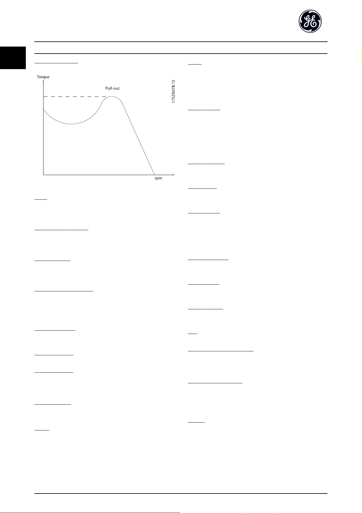
Break-away torque
η
DRIVE
The efficiency of the drive is defined as the ratio between
the power output and the power input.
Start-disable command
A stop command belonging to the group 1 control
commands - see this group.
Stop command
See Control commands.
References:
Advanced Vector Control
If compared with standard voltage/frequency ratio control,
(Adv. Vector Control) improves the dynamics and the
stability, both when the speed reference is changed and in
relation to the load torque.
Analog Reference
A signal transmitted to the analog inputs 53 or 54, can be
voltage or current.
Binary Reference
A signal transmitted to the serial communication port.
Preset Reference
A defined preset reference to be set from -100% to +100%
of the reference range. Selection of eight preset references
via the digital terminals.
Pulse Reference
A pulse frequency signal transmitted to the digital inputs
(terminal 29 or 33).
Ref
MAX
Determines the relationship between the reference input
at 100% full scale value (typically 10V, 20mA) and the
resulting reference. The maximum reference value set in
F-53 Maximum Reference.
Ref
MIN
Determines the relationship between the reference input
at 0% value (typically 0V, 0mA, 4mA) and the resulting
reference. The minimum reference value set in
F-52 Minimum Reference.
Miscellaneous:
Analog Inputs
The analog inputs are used for controlling various
functions of the drive.
There are two types of analog inputs:
Current input, 0-20mA and 4-20mA
Voltage input, 0-10V DC
Voltage input, -10 - +10V DC.
Analog Outputs
The analog outputs can supply a signal of 0-20mA,
4-20mA.
Auto Tuning
The Auto Tune algorithm determines the electrical
parameters for the connected motor at standstill.
Brake Resistor
The brake resistor is a module capable of absorbing the
brake power generated in regenerative braking. This
regenerative braking power increases the intermediate
circuit voltage and a brake chopper ensures that the
power is transmitted to the brake resistor.
CT Characteristics
Constant torque characteristics used for all applications
such as conveyor belts, displacement pumps and cranes.
Digital Inputs
The digital inputs can be used for controlling various
functions of the drive.
Digital Outputs
The drive features two Solid State outputs that can supply
a 24V DC (max. 40mA) signal.
DSP
Digital Signal Processor.
Electronic Thermal Overload
The Electronic Overload is a thermal load calculation based
on present load and time. Its purpose is to estimate the
motor temperature.
Intermittent Duty Cycle
An intermittent duty rating refers to a sequence of duty
cycles. Each cycle consists of an on-load and an off-load
period. The operation can be either periodic duty or nonperiodic duty.
Keypad
The Keypad makes up a complete interface for control and
programming of the drive. The keypad is detachable and
can be installed up to 10ft/3M from the drive, i.e. in a front
panel with the optional Remote Keypad Mounting Kit
(RMKYPDAC)..
6
Page 8

Introduction AF-600 FP Programming Guide
Logic Controller (LC)
The LC is a sequence of user defined actions executed
when the associated user defined events are evaluated as
true by the Logic Controller. (Par. group LC-##).
lsb
Least significant bit.
msb
Most significant bit.
MCM
Short for Mille Circular Mil, an American measuring unit for
cable cross-section. 1 MCM = 0.5067mm
2
.
On-line/Off-line Parameters
Changes to on-line parameters are activated immediately
after the data value is changed. Changes to off-line
parameters are not activated until you enter [OK] on the
keypad.
Process PID
The PID control maintains the desired speed, pressure,
temperature, etc. by adjusting the output frequency to
match the varying load.
PCD
Process Control Data
Power Cycle
Switch off the mains until display (keypad) is dark – then
turn power on again
Trip
A state entered in fault situations, e.g. if the drive is
subject to an over-temperature or when the drive is
protecting the motor, process or mechanism. Restart is
prevented until the cause of the fault has disappeared and
the trip state is cancelled by activating reset or, in some
cases, by being programmed to reset automatically. Trip
may not be used for personal safety.
Trip Locked
A state entered in fault situations when the drive is
protecting itself and requiring physical intervention, e.g. if
the drive is subject to a short circuit on the output. A
locked trip can only be cancelled by cutting off mains,
removing the cause of the fault, and reconnecting the
drive. Restart is prevented until the trip state is cancelled
by activating reset or, in some cases, by being
programmed to reset automatically. Trip may not be used
for personal safety.
VT Characteristics
Variable torque characteristics used for pumps and fans.
60° AVM
Switching pattern called 60°
Modulation (F-37 Adv. Switching Pattern).
Power Factor
The power factor is the relation between I
Pulse Input/Incremental Encoder
An external, digital pulse transmitter used for feeding back
information on motor speed. The encoder is used in
applications where great accuracy in speed control is
required.
RCD
Residual Current Device.
Set-up
You can save parameter settings in four Set-ups. Change
between the four parameter Set-ups and edit one Set-up,
Power factor
The power factor for 3-phase control:
I1 x cos
=
I
RMS
The power factor indicates to which extent the drive
imposes a load on the mains supply.
The lower the power factor, the higher the I
same kW performance.
while another Set-up is active.
I
=
SFAVM
Switching pattern called
Stator Flux oriented Asynchronous
Vector Modulation (F-37 Adv. Switching Pattern).
Slip Compensation
The drive compensates for the motor slip by giving the
frequency a supplement that follows the measured motor
load keeping the motor speed almost constant.
STW
Status Word
Drive Standard Bus
Includes RS-485 bus with Drive protocol or MC protocol.
See O-30 Protocol.
Thermistor:
RMS
In addition, a high power factor indicates that the different
harmonic currents are low.
The frequency converters' built-in DC link reactor produce
a high power factor, which minimizes the imposed load on
the mains supply.
WARNING
The voltage of the drive is dangerous whenever connected
to mains. Incorrect installation of the motor, drive or
network may cause death, serious personal injury or
damage to the equipment. Consequently, the instructions
in this manual, as well as national and local rules and
safety regulations, must be complied with.
A temperature-dependent resistor placed where the
temperature is to be monitored (drive or motor).
1
1
Asynchronous Vector
and I
1
3 x U x
I
1
I
RMS
2
+
I
7
I
cos
1
I
RMS
since cos
+ .. +
ϕ
ϕ1 = 1
2
I
n
3 x U x
=
ϕ1
=
2
2
+
I
I
1
5
RMS
.
RMS
for the
7
Page 9

Introduction AF-600 FP Programming Guide
1
Safety Regulations
1. The mains supply to the drive must be disconnected whenever repair work is to be carried out.
Check that the mains supply has been disconnected and that the necessary time has elapsed
before removing motor and mains supply plugs.
2. The [OFF] button on the keypad of the drive does
not disconnect the mains supply and
consequently it must not be used as a safety
switch.
3. The equipment must be properly earthed, the
user must be protected against supply voltage
and the motor must be protected against
overload in accordance with applicable national
and local regulations.
4. The earth leakage current exceeds 3.5mA.
5. Protection against motor overload is not included
in the factory setting. If this function is desired,
set F-10 Electronic Overload to data value Elec. OL
trip 1 [4] or data value Elec. OL warning 1 [3].
6. Do not remove the plugs for the motor and
mains supply while the drive is connected to
mains. Check that the mains supply has been
disconnected and that the necessary time has
elapsed before removing motor and mains plugs.
7. Please note that the drive has more voltage
sources than L1, L2 and L3, when load sharing
(linking of DC intermediate circuit) or external
24V DC are installed. Check that all voltage
sources have been disconnected and that the
necessary time has elapsed before commencing
repair work.
Warning against unintended start
1. The motor can be brought to a stop by means of
digital commands, bus commands, references or
a local stop, while the drive is connected to
mains. If personal safety considerations (e.g. risk
of personal injury caused by contact with moving
machine parts following an unintentional start)
make it necessary to ensure that no unintended
start occurs, these stop functions are not
sufficient. In such cases the mains supply must be
disconnected.
2. The motor may start while setting the
parameters. If this means that personal safety
may be compromised (e.g. personal injury caused
by contact with moving machine parts), motor
starting must be prevented by disconnection of
the motor connection.
3. A motor that has been stopped with the mains
supply connected, may start if faults occur in the
electronics of the drive, through temporary
overload or if a fault in the power supply grid or
motor connection is remedied. If unintended start
must be prevented for personal safety reasons
(e.g. risk of injury caused by contact with moving
machine parts), the normal stop functions of the
drive are not sufficient. In such cases the mains
supply must be disconnected.
4. Control signals from, or internally within, the
drive may in rare cases be activated in error, be
delayed or fail to occur entirely. When used in
situations where safety is critical, e.g. when
controlling the electromagnetic brake function of
a hoist application, these control signals must not
be relied on exclusively.
WARNING
High Voltage
Touching the electrical parts may be fatal - even after the
equipment has been disconnected from mains.
Also make sure that other voltage inputs have been
disconnected, such as external 24 V DC, load sharing
(linkage of DC intermediate circuit), as well as the motor
connection for kinetic back up.
Systems where frequency converters are installed must, if
necessary, be equipped with additional monitoring and
protective devices according to the valid safety regulations,
e.g law on mechanical tools, regulations for the prevention
of accidents etc. Modifications on the frequency converters
by means of the operating software are allowed.
NOTE
Hazardous situations shall be identified by the machine
builder/ integrator who is responsible for taking necessary
preventive means into consideration. Additional
monitoring and protective devices may be included, always
according to valid national safety regulations, e.g. law on
mechanical tools, regulations for the prevention of
accidents.
Protection Mode
Once a hardware limit on motor current or dc-link voltage
is exceeded the frequency converter will enter “Protection
mode”. “Protection mode” means a change of the PWM
modulation strategy and a low switching frequency to
minimize losses. This continues 10 sec after the last fault
and increases the reliability and the robustness of the
frequency converter while re-establishing full control of the
motor.
8
Page 10
Introduction AF-600 FP Programming Guide
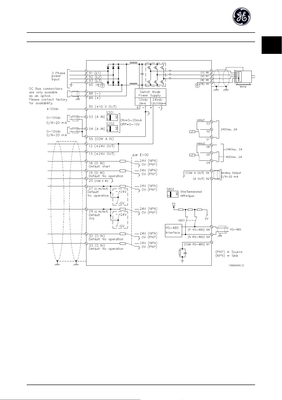
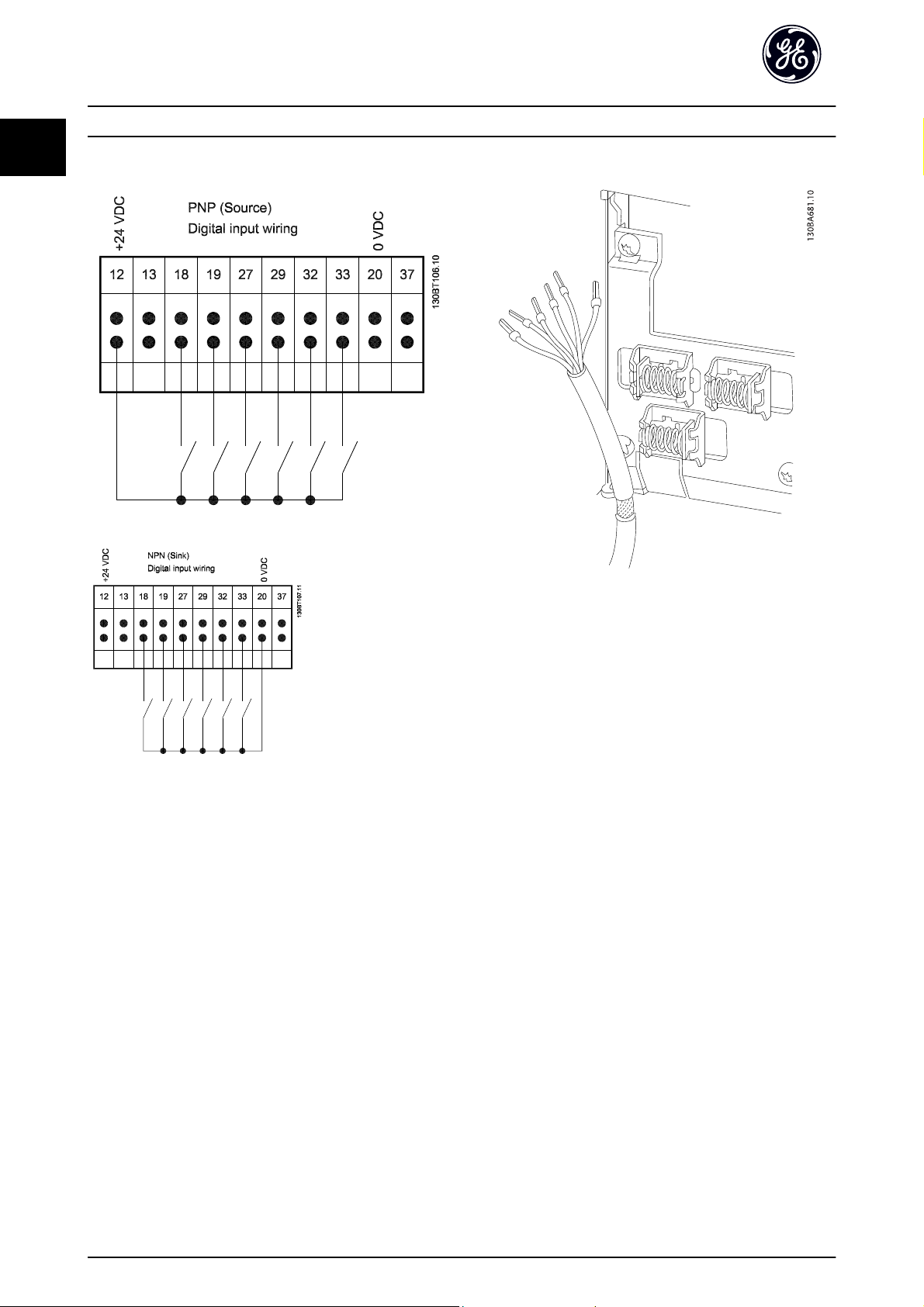
1.1.6 Electrical wiring - control cables
1
1
Illustration 1.1 Diagram showing all electrical terminals without options.
Very long control cables and analog signals may in rare cases and depending on installation result in 50/60 Hz earth loops
due to noise from mains supply cables.
If this occurs, it may be necessary to break the screen or insert a 100 nF capacitor between screen and chassis.
The digital and analog inputs and outputs must be connected separately to the common inputs (terminal 20, 55, 39) of the
frequency converter to avoid ground currents from both groups to affect other groups. For example, switching on the
digital input may disturb the analog input signal.
9
Page 11
Introduction AF-600 FP Programming Guide
1
Input polarity of control terminals
Control cables must be screened/armoured.
See section entitled Earthing of Screened/Armoured Control
Cables for the correct termination of control cables.
10
Page 12
How to Program AF-600 FP Programming Guide
2
2How to Program
2.1 Keypad
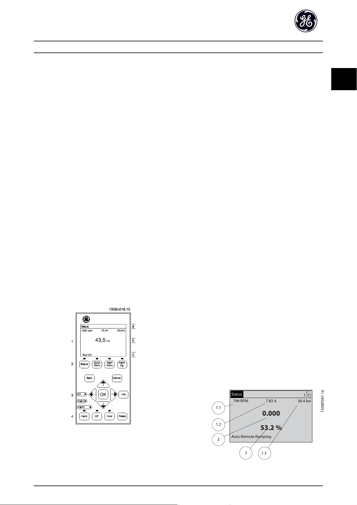
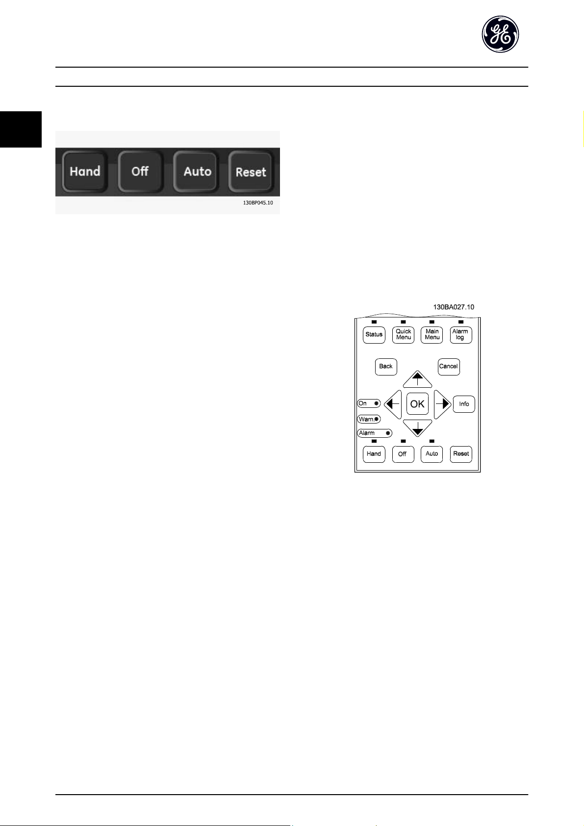
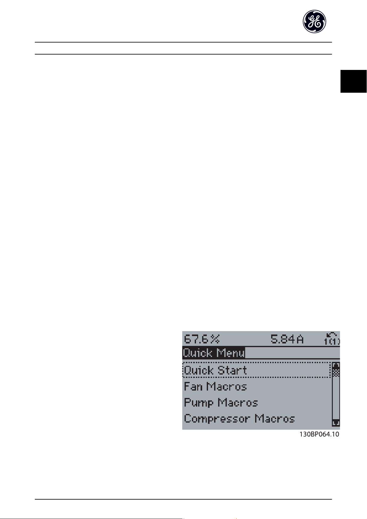
2.1.1 How to operate graphical keypad
The keypad is divided into four functional groups:
1. Graphical display with Status lines.
2. Menu keys and indicator lights (LEDs) - selecting
mode, changing parameters and switching
between display functions.
3. Navigation keys and indicator lights (LEDs).
4. Operation keys and indicator lights (LEDs).
Graphical display:
The LCD-display is back-lit with a total of 6 alpha-numeric
lines. All data is displayed on the keypad which can show
up to five operating variables while in [Status] mode.
Display lines:
a. Status line: Status messages displaying icons and
graphics.
b. Line 1-2: Operator data lines displaying data and
variables defined or chosen by the user. By
pressing the [Status] key, up to one extra line can
be added.
c. Status line: Status messages displaying text.
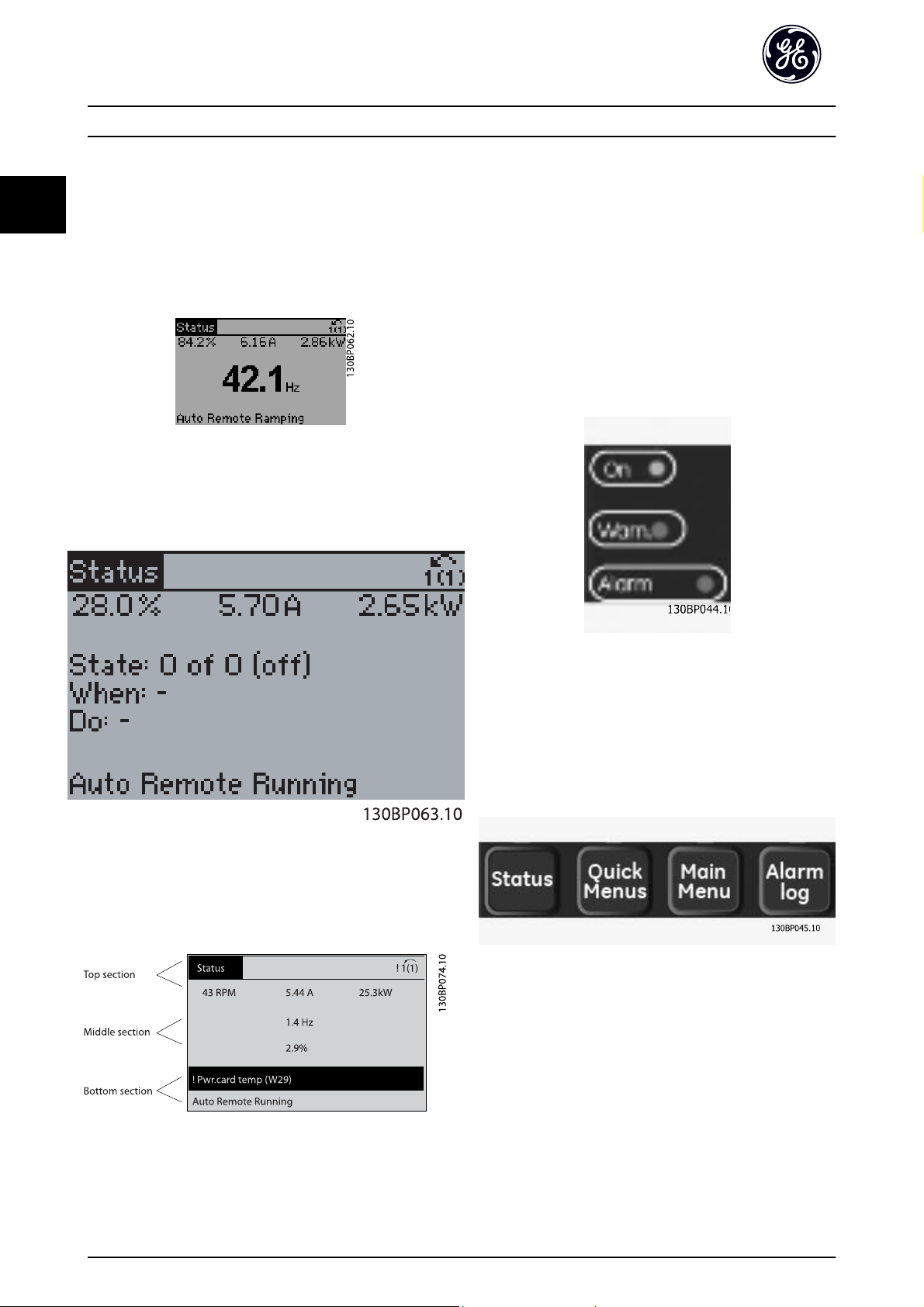
The display is divided into 3 sections:
2
Top section (a) shows the status when in status mode or
up to 2 variables when not in status mode and in the case
of Alarm/Warning.
The number of the Active Set-up (selected as the Active
Set-up in K-10 Active Set-up) is shown. When programming
in another Set-up than the Active Set-up, the number of
the Set-up being programmed appears to the right in
brackets.
The Middle section (b) shows up to 5 variables with related
unit, regardless of status. In case of alarm/warning, the
warning is shown instead of the variables.
The Bottom section (c) always shows the state of the
frequency converter in Status mode.
It is possible to toggle between three status read-out
displays by pressing the [Status] key.
Operating variables with different formatting are shown in
each status screen - see below.
Each value / measurement readout parameter selected in
K-20 Display Line 1.1 Small to K-24 Display Line 3 Large has
its own scale and number of digits after a possible decimal
point. Larger numeric values are displayed with few digits
after the decimal point.
Ex.: Current readout
5.25 A; 15.2 A 105 A.
Status display I:
This read-out state is standard after start-up or restore.
Use [INFO] to obtain information about the value/
measurement linked to the displayed operating variables
(1.1, 1.2, 1.3, 2, and 3).
See the operating variables shown in the display in this
illustration. 1.1, 1.2 and 1.3 are shown in small size. 2 and
3 are shown in medium size.
11
Page 13
How to Program AF-600 FP Programming Guide
2
Status display II:
See the operating variables (1.1, 1.2, 1.3, and 2) shown in
the display in this illustration.
In the example, Speed, Motor current, Motor power and
Frequency are selected as variables in the first and second
lines.
1.1, 1.2 and 1.3 are shown in small size. 2 is shown in large
size.
Status display III:
This state displays the event and action of the Logic
Controller. For further information, see section Logic
Controller.
Indicator lights (LEDs):
If certain threshold values are exceeded, the alarm and/or
warning LED lights up. A status and alarm text appear on
the keypad.
The On LED is activated when the frequency converter
receives power from mains voltage, a DC bus terminal, or
an external 24 V supply. At the same time, the back light is
on.
Green LED/On: Control section is working.
•
Yellow LED/Warn.: Indicates a warning.
•
Flashing Red LED/Alarm: Indicates an alarm.
•
Display Contrast Adjustment
Press [status] and [
Press [status] and [
] for darker display
▲
] for brighter display
▼
Keys
Menu keys
The menu keys are divided into functions. The keys below
the display and indicator lamps are used for parameter setup, including choice of display indication during normal
operation.
[Status]
indicates the status of the frequency converter and/or the
motor. 3 different readouts can be chosen by pressing the
[Status] key:
5 line readouts, 4 line readouts or Logic Controller.
Use [Status] for selecting the mode of display or for
changing back to Display mode from either the Quick
Menu mode, the Main Menu mode or Alarm mode. Also
use the [Status] key to toggle single or double read-out
mode.
12
Page 14
How to Program AF-600 FP Programming Guide
2
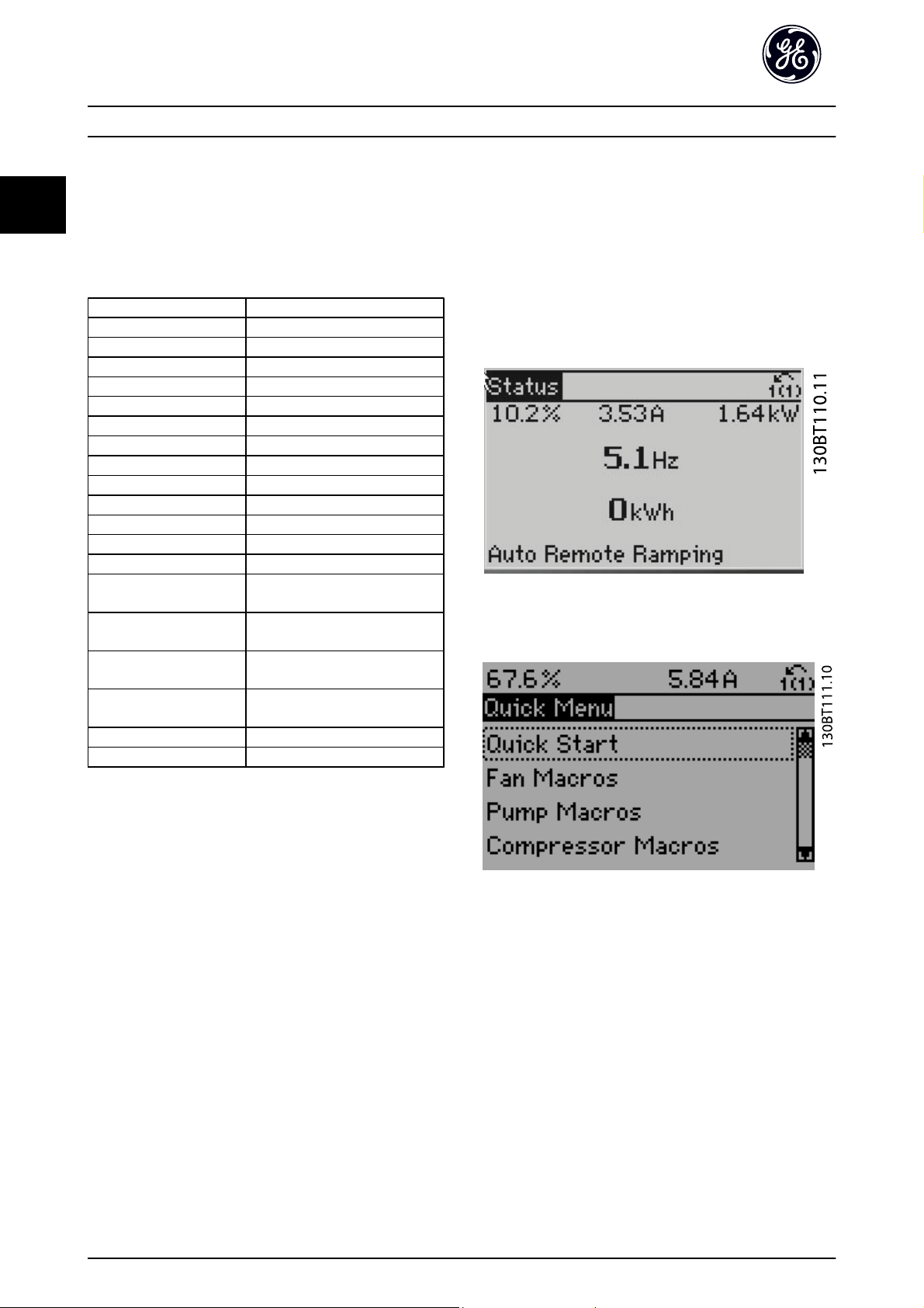
[Quick Menu]
allows quick set-up of the frequency converter. The most
common AF-600 FP functions can be programmed here.
The [Quick Menu] consists of:
-Quick Start
-Fan Macros
-Pump Macros
- Compressor Macros
- Closed Loop
- Parameter Data Check
-Trendings
The Function set-up provides quick and easy access to all
parameters required for the majority of AF-600 FP
applications including most VAV and CAV supply and
return fans, cooling tower fans, Primary, Secondary and
Condenser Water Pumps and other pump, fan and
compressor applications. Amongst other features it also
includes parameters for selecting which variables to display
on the keypad, digital preset speeds, scaling of analog
references, closed loop single zone and multi-zone
applications and specific functions related to Fans, Pumps
and Compressors.
[Alarm Log]
displays an Alarm list of the ten latest alarms (numbered
A1-A10). To obtain additional details about an alarm, use
the arrow keys to manoeuvre to the alarm number and
press [OK]. Information is displayed about the condition of
the frequency converter before it enters the alarm mode.
The Alarm log button on the keypad allows access to both
Alarm log and Maintenance log.
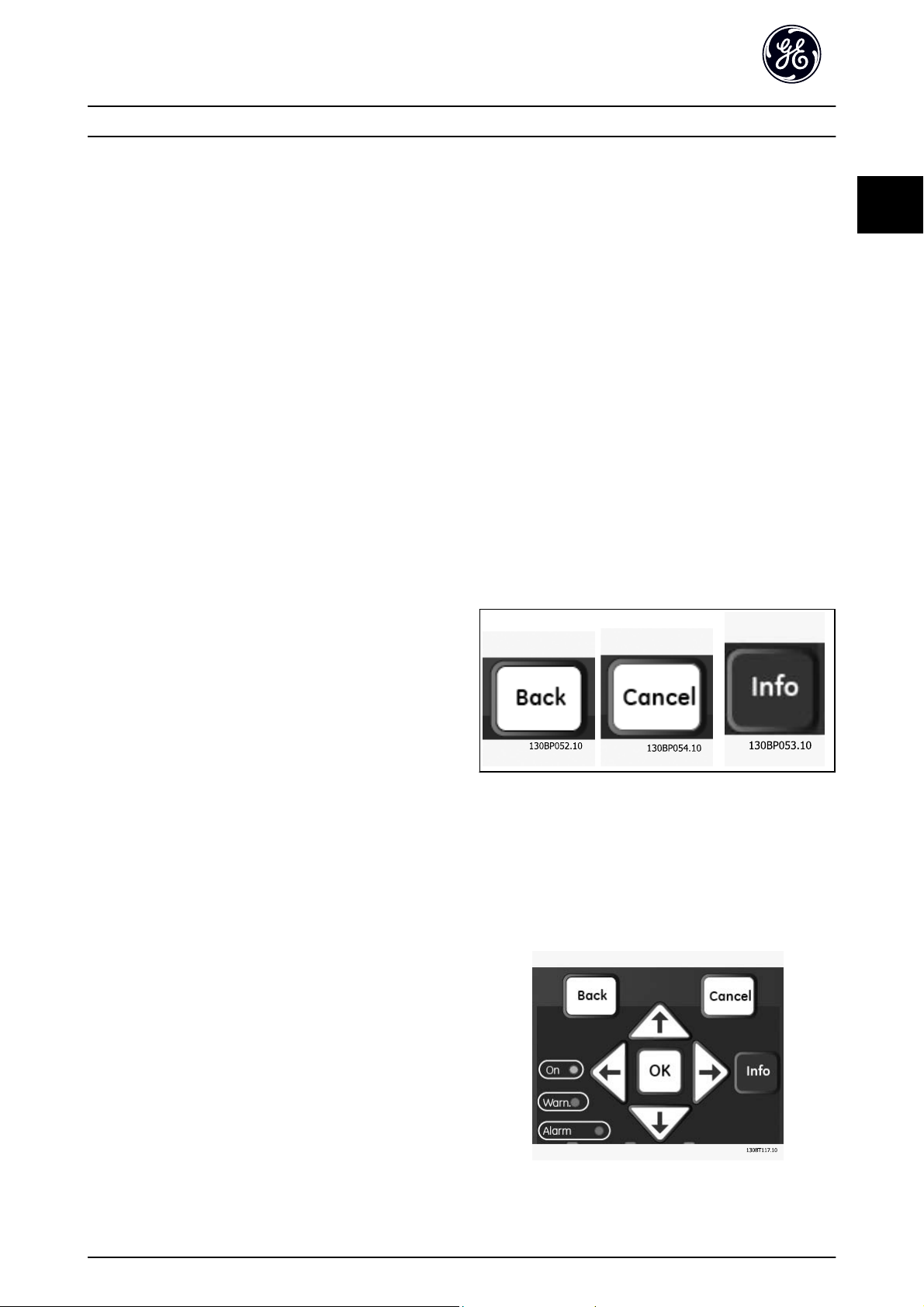
[Back]
reverts to the previous step or layer in the navigation
structure.
[Cancel]
last change or command will be cancelled as long as the
display has not been changed.
[Info]
displays information about a command, parameter, or
function in any display window. [Info] provides detailed
information when needed.
Exit Info mode by pressing either [Info], [Back], or [Cancel].
2
The Quick Menu parameters can be accessed immediately
unless a password has been created via K-60 Main Menu
Password, K-61 Access to Main Menu w/o Password,
K-65 Quick Menu Password or K-66 Access to Quick Menu w/
o Password.
It is possible to switch directly between Quick Menu mode
and Main Menu mode.
[Main Menu]
is used for programming all parameters.The Main Menu
parameters can be accessed immediately unless a
password has been created via K-60 Main Menu Password,
K-61 Access to Main Menu w/o Password, K-65 Quick Menu
Password or K-66 Access to Quick Menu w/o Password. For
the majority of AF-600 FP applications it is not necessary
to access the Main Menu parameters but instead the Quick
Menu, Quick Set-up and Function Set-up provides the
simplest and quickest access to the typical required
parameters.
It is possible to switch directly between Main Menu mode
and Quick Menu mode.
Parameter shortcut can be carried out by pressing down
the [Main Menu] key for 3 seconds. The parameter shortcut
allows direct access to any parameter.
Navigation Keys
The four navigation arrows are used to navigate between
the different choices available in [Quick Menu], [Main
Menu] and [Alarm Log]. Use the keys to move the cursor.
[OK] is used for choosing a parameter marked by the
cursor and for enabling the change of a parameter.
13
Page 15
How to Program AF-600 FP Programming Guide
2
Operation Keys for local control are found at the bottom
of the keypad.
[Hand]
enables control of the frequency converter via the keypad.
[Hand] also starts the motor, and it is now possible to
enter the motor speed data by means of the arrow keys.
The key can be selected as Enable [1] or Disable [0] via
K-40 [Hand] Button on Keypad.
The following control signals will still be active when
[Hand] is activated:
[Hand] - [Off] - [Auto]
•
Reset
•
Coasting stop inverse
•
Reversing
•
Set-up select lsb - Set-up select msb
•
Stop command from serial communication
•
Quick stop
•
DC brake
•
[Reset]
is used for resetting the frequency converter after an alarm
(trip). It can be selected as Enable [1] or Disable [0] via
K-43 [Reset] Button on Keypad.
The parameter shortcut can be carried out by holding
down the [Main Menu] key for 3 seconds. The parameter
shortcut allows direct access to any parameter.
2.1.2 Quick Transfer of Parameter Settings
between Multiple Frequency
Converters
Once the set-up of a drive is complete, we recommend
that you store the data in the keypad or on a PC via Drive
Control Tool Software DCT 10.
NOTE
External stop signals activated by means of control signals
or a serial bus will override a “start” command via the
keypad.
[Off]
stops the connected motor. The key can be selected as
Enable [1] or Disable [0] via K-41 [Off] Button on Keypad. If
no external stop function is selected and the [Off] key is
inactive the motor can only be stopped by disconnecting
the mains supply.
[Auto]
enables the frequency converter to be controlled via the
control terminals and/or serial communication. When a
start signal is applied on the control terminals and/or the
bus, the frequency converter will start. The key can be
selected as Enable [1] or Disable [0] via K-42 [Auto] Button
on Keypad.
NOTE
An active HAND-OFF-AUTO signal via the digital inputs has
higher priority than the control keys [Hand] – [Auto].
Data storage in keypad
1. Go to K-50 Keypad Copy
2. Press the [OK] key
3. Select “All to keypad”
4. Press the [OK] key
All parameter settings are now stored in the keypad
indicated by the progress bar. When 100% is reached,
press [OK].
NOTE
Stop the motor before performing this operation.
You can now connect the keypad to another drive and
copy the parameter settings to this drive as well.
Data transfer from keypad to drive
1. Go to K-50 Keypad Copy
2. Press the [OK] key
3. Select “All from keypad”
4. Press the [OK] key
14
Page 16
How to Program AF-600 FP Programming Guide
2
The parameter settings stored in the keypad are now
transferred to the drive indicated by the progress bar.
When 100% is reached, press [OK].
NOTE
Stop the motor before performing this operation.
2.1.3 Parameter Set-Up
The frequency converter can be used for practically all
assignments, thus offering a significant number of
parameters. The series offers a choice between two
programming modes - the Quick Menu mode and the
Main Menu mode.
The latter provides access to all parameters. The former
takes the user through a few parameters making it
possible to program the majority of AF-600 FP
applications.
Regardless of the mode of programming, you can change
a parameter both in the Quick Menu mode and in the
Main Menu mode.
2.1.4 Quick Menu Mode
Parameter Data
The keypad provides access to all parameters listed under
the Quick Menus. To set parameters using the [Quick
Menu] button - enter or change parameter data or settings
in accordance with the following procedure:
1. Press Quick Menu button then press Quick Start
2.
Use the [
you want to change
3. Press [OK]
4.
Use [
parameter setting
5. Press [OK]
6. To move to a different digit within a parameter
setting, use the [
7. Highlighted area indicates digit selected for
change
8. Press [Cancel] button to disregard change, or
press [OK] to accept change and enter the new
setting
Example of changing parameter data
Assume parameter F-07 Accel Time 1 is set to 6 seconds
and you want to change it to 10 seconds. Use the
following procedure:
] and [▼] buttons to find the parameter
▲
] and [▼] buttons to select the correct
▲
] and [▶] buttons
◀
4.
With the [
5. Press [OK]
6. Use the arrow keys to change the 6.00 to 10.00.
7. Press [OK]
The drive will now accelerate to rated speed in 10 seconds
instead of 6 seconds.
It is recommended to do the set-up in the order that the
parameters are listed!
Select [Parameter Data Check] to get information about:
The last 10 changes. Use the up/down navigation
•
keys to scroll between the last 10 changed
parameters.
The changes made since default setting.
•
Select [Trendings]:
to get information about the display line read-outs. The
information is shown as graphs.
Only display parameters selected in K-20 Display Line 1.1
Small and K-24 Display Line 3 Large can be viewed. It is
possible to store up to 120 samples in the memory for
later reference.
Efficient Parameter Set-up for AF-600 FP Applications:
The parameters can easily be set up for the vast majority
of the AF-600 FP applications only by using the [Quick
Setup] option.
After pressing [Quick Menu], the different choices in the
Quick Menu are listed.
Example of using the Quick Setup option:
] button find par. F-07 Accel Time 1
▼
NOTE
A complete description of the function is found in the
parameter sections of this manual.
Illustration 2.1 Quick Menu view.
2
1. Press Quick Menu key
2. Choose Quick Start
3. Press [OK]
15
Page 17
How to Program AF-600 FP Programming Guide
2
The Quick Setup menu gives access to the most important
setup parameters of the frequency converter. After
programming the frequency converter will, in most cases,
be ready for operation. The Quick Setup parameters are
shown in the table below. A complete description of the
function is given in the parameter description sections of
this manual.
Parameter [Units]
K-01 Language
K-02 Motor Speed Unit
P-02 Motor Power [HP]*[HP]
P-07 Motor Power [kW] [kW]
F-05 Motor Rated Voltage [V]
F-04 Base Frequency [Hz]
P-03 Motor Current [A]
P-06 Base Speed [RPM]
F-01 Frequency Setting 1
F-02 Operation Method
F-07 Accel Time 1 [s]
F-08 Decel Time 1 [s]
F-10 Electronic Overload
F-15 Motor Speed High Limit
[Hz]*
F-16 Motor Speed Low Limit
[Hz]*
F-17 Motor Speed High Limit
[RPM]
F-18 Motor Speed Low Limit
[RPM]
H-08 Reverse Lock
P-04 Auto Tune
[Hz]
[Hz]
[RPM]
[RPM]
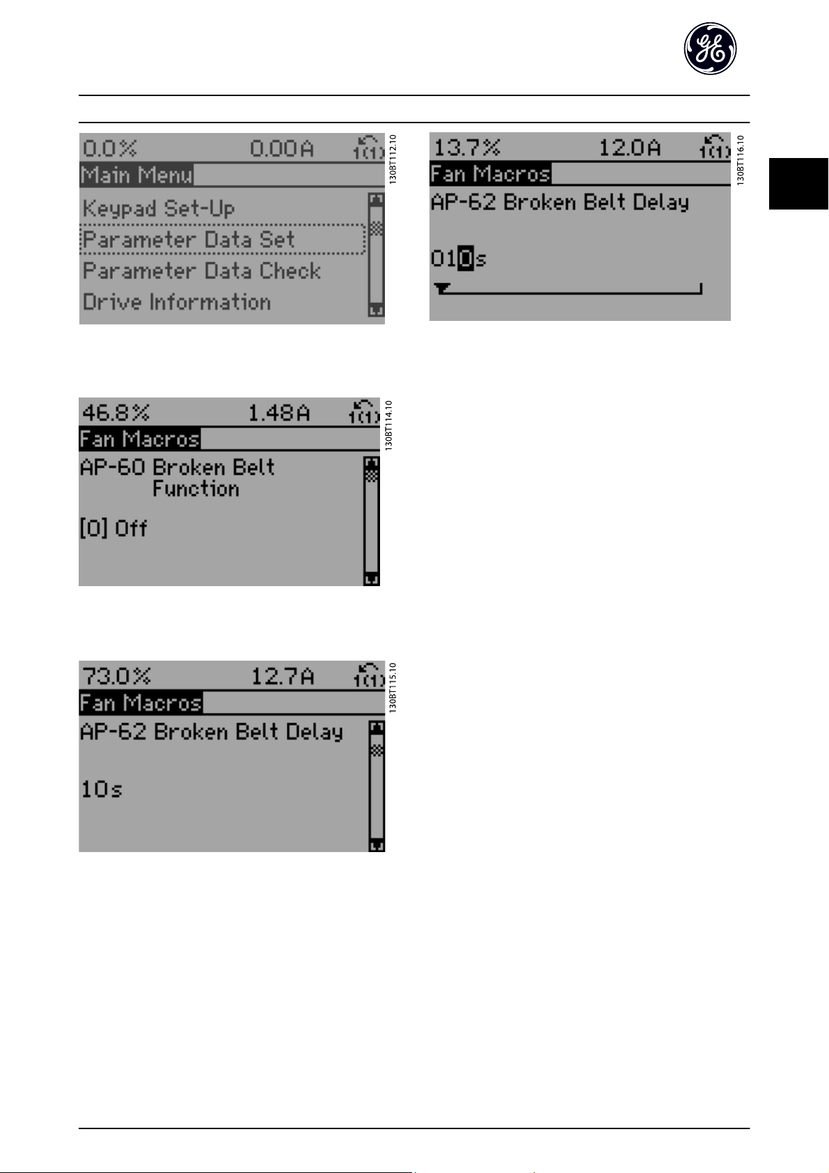
2.1.5 Macros
The Macros provide quick and easy access to all
parameters required for the majority of AF-600 FP
applications including most VAV and CAV supply and
return fans, cooling tower fans, Primary, Secondary and
Condenser Water Pumps and other pump, fan and
compressor applications.
How to access Macros - example
Illustration 2.2 Step 1: Turn on the frequency converter (green
LED lights)
Table 2.1 Quick Setup parameters
*The display showing depends on choices made in
K-02 Motor Speed Unit and K-03 Regional Settings. The
default settings of K-02 Motor Speed Unit and K-03 Regional
Settings depend on which region of the world the
frequency converter is supplied to but can be reprogrammed as required.
Illustration 2.3 Step 2: Press the [Quick Menus] button (Quick
Menus choices appear).
16
Page 18
How to Program AF-600 FP Programming Guide
2
2
Illustration 2.4 Step 3: Use the up/down navigation keys to scroll
down to Fan Macros. Press [OK].
Illustration 2.5 Step 4: Use the up/down navigation keys to scroll
down to find AP-62 Broken Belt Delay.
Illustration 2.7 Step 6: Use the up/down navigation keys to
change the delay time.
Illustration 2.6 Step 5: Press [OK].
17
Page 19

How to Program AF-600 FP Programming Guide
Function Set-ups parameters
The Quick Menu parameters are grouped in the following way:
2
Application Settings
Fan Macros Pump Macros Compressor Macros
AP-60 Broken Belt Function AP-20 Low Power Auto Set-up H-43 Torque Characteristics
AP-61 Broken Belt Torque AP-21 Low Power Detection F-24 Holding Time
AP-62 Broken Belt Delay AP-22 Low Speed Detection AP-75 Short Cycle Protection
C-40 Semi-Auto Jump Freq Set-up AP-23 No-Flow Function AP-76 Interval between Starts
H-43 Torque Characteristics AP-24 No-Flow Delay AP-77 Minimum Run Time
AP-22 Low Speed Detection AP-40 Minimum Run Time E-51 Terminal 27 Mode
AP-23 No-Flow Function AP-41 Minimum Sleep Time E-52 Terminal 29 Mode
AP-24 No-Flow Delay AP-42 Wake-up Speed [RPM] E-03 Terminal 27 Digital Input
AP-40 Minimum Run Time AP-43 Wake-up Speed [Hz] E-04 Terminal 29 Digital Input
AP-41 Minimum Sleep Time AP-44 Wake-up Ref./FB Difference E-24 Function Relay
AP-42 Wake-up Speed [RPM] AP-45 Setpoint Boost H-09 Start Mode
AP-43 Wake-up Speed [Hz] AP-46 Maximum Boost Time H-36 Trip Speed Low [RPM]
AP-44 Wake-up Ref./FB Difference AP-26 Dry Pump Function H-37 Trip Speed Low [Hz]
AP-45 Setpoint Boost AP-27 Dry Pump Delay
AP-46 Maximum Boost Time AP-80 Flow Compensation
B-10 Brake Function AP-81 Square-linear Curve Approximation
B-16 AC brake Max. Current AP-82 Work Point Calculation
B-17 Over-voltage Control AP-83 Speed at No-Flow [RPM]
H-09 Start Mode AP-84 Speed at No-Flow [Hz]
F-24 Holding Time AP-85 Speed at Design Point [RPM]
H-80 Function at Stop AP-86 Speed at Design Point [Hz]
B-00 DC Hold Current AP-87 Pressure at No-Flow Speed
H-08 Reverse Lock AP-88 Pressure at Rated Speed
AP-89 Flow at Design Point
AP-90 Flow at Rated Speed
H-43 Torque Characteristics
H-09 Start Mode
18
Page 20

How to Program AF-600 FP Programming Guide
2
Closed Loop Settings
Single Zone Int. Set Point Single Zone Ext. Set Point Multi Zone / Adv
H-40 Configuration Mode H-40 Configuration Mode H-40 Configuration Mode
CL-12 Reference/Feedback Unit CL-12 Reference/Feedback Unit F-01 Frequency Setting 1
CL-13 Minimum Reference/Feedb. CL-13 Minimum Reference/Feedb. C-30 Frequency Command 2
CL-14 Maximum Reference/Feedb. CL-14 Maximum Reference/Feedb. CL-00 Feedback 1 Source
AN-22 Terminal 54 Low Current AN-10 Terminal 53 Low Voltage CL-01 Feedback 1 Conversion
AN-24 Terminal 54 Low Ref./Feedb. Value AN-11 Terminal 53 High Voltage CL-02 Feedback 1 Source Unit
AN-25 Terminal 54 High Ref./Feedb. Value AN-12 Terminal 53 Low Current CL-03 Feedback 2 Source
AN-26 Terminal 54 Filter Time Constant AN-13 Terminal 53 High Current CL-04 Feedback 2 Conversion
AN-27 Terminal 54 Live Zero AN-14 Terminal 53 Low Ref./Feedb. Value CL-05 Feedback 2 Source Unit
AN-00 Live Zero Timeout Time AN-15 Terminal 53 High Ref./Feedb. Value CL-06 Feedback 3 Source
AN-01 Live Zero Timeout Function AN-22 Terminal 54 Low Current CL-07 Feedback 3 Conversion
CL-21 Setpoint 1 AN-24 Terminal 54 Low Ref./Feedb. Value CL-08 Feedback 3 Source Unit
CL-81 PID Normal/ Inverse Control AN-25 Terminal 54 High Ref./Feedb. Value CL-12 Reference/Feedback Unit
CL-82 PID Start Speed [RPM] AN-26 Terminal 54 Filter Time Constant CL-13 Minimum Reference/Feedb.
CL-83 PID Start Speed [Hz] AN-27 Terminal 54 Live Zero CL-14 Maximum Reference/Feedb.
CL-93 PID Proportional Gain AN-00 Live Zero Timeout Time AN-10 Terminal 53 Low Voltage
CL-94 PID Integral Time AN-01 Live Zero Timeout Function AN-11 Terminal 53 High Voltage
CL-81 PID Normal/ Inverse Control AN-12 Terminal 53 Low Current
CL-82 PID Start Speed [RPM] AN-13 Terminal 53 High Current
CL-83 PID Start Speed [Hz] AN-14 Terminal 53 Low Ref./Feedb. Value
CL-93 PID Proportional Gain AN-15 Terminal 53 High Ref./Feedb. Value
CL-94 PID Integral Time AN-16 Terminal 53 Filter Time Constant
AN-17 Terminal 53 Live Zero
AN-20 Terminal 54 Low Voltage
AN-21 Terminal 54 High Voltage
AN-22 Terminal 54 Low Current
AN-23 Terminal 54 High Current
AN-24 Terminal 54 Low Ref./Feedb. Value
AN-25 Terminal 54 High Ref./Feedb. Value
AN-26 Terminal 54 Filter Time Constant
AN-27 Terminal 54 Live Zero
AN-00 Live Zero Timeout Time
AN-01 Live Zero Timeout Function
H-76 Warning Feedback Low
H-77 Warning Feedback High
CL-20 Feedback Function
CL-21 Setpoint 1
CL-22 Setpoint 2
CL-81 PID Normal/ Inverse Control
CL-82 PID Start Speed [RPM]
CL-83 PID Start Speed [Hz]
CL-93 PID Proportional Gain
CL-94 PID Integral Time
CL-70 Closed Loop Type
CL-71 PID Performance
CL-72 PID Output Change
CL-73 Minimum Feedback Level
CL-74 Maximum Feedback Level
CL-79 PID Autotuning
2
19
Page 21
How to Program AF-600 FP Programming Guide
2
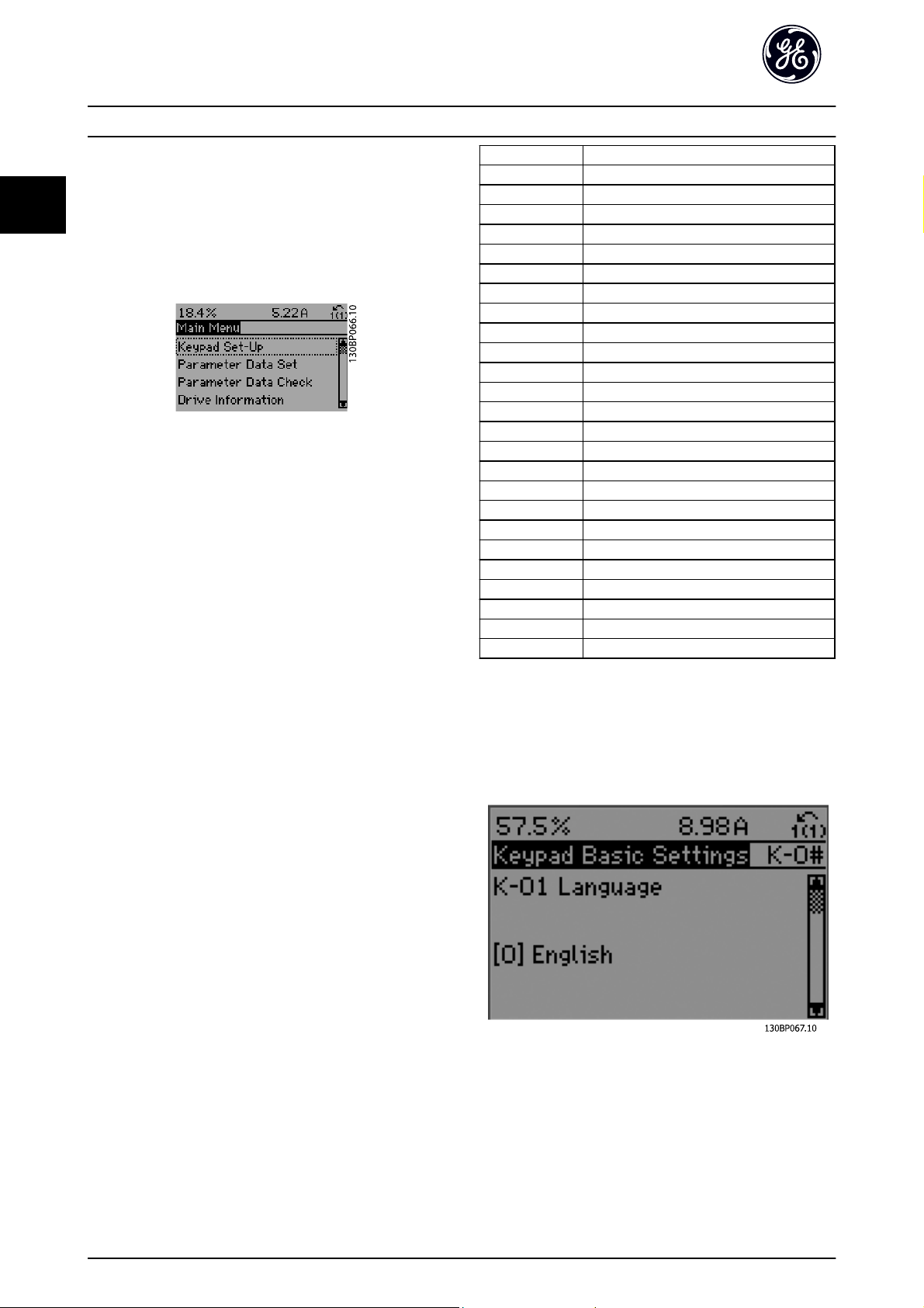
2.1.6 Main Menu Mode
Select the Main Menu mode by pressing the [Main Menu]
key. The below read-out appears on the display.
The middle and bottom sections on the display show a list
of parameter groups which can be chosen by toggling the
up and down buttons.
Each parameter has a name and number which remain the
same regardless of the programming mode. In the Main
Menu mode, the parameters are divided into groups. The
first digit of the parameter number (from the left) indicates
the parameter group number.
All parameters can be changed in the Main Menu.
However, depending on the choice of configuration
(H-40 Configuration Mode), some parameters can be
hidden.
2.1.7 Parameter Selection
Group no. Parameter group:
KKeypad Set-up
F Fundamental Parameters
EDigital In/Outs
C Frequency Control Functions
P Motor Data
H High Perf Parameters
AN Analog In/Out
SP Special Functions
O Options/comms
AO Analog I/O Option
DN DeviceNet
PB Profibus
LN LonWorks
BN BACnet
ID Drive Information
DR Data Readouts
LG Logs & I/O Opt. Status
AP HVAC Appl. Param.
FB Fire/Bypass Operation
TTimed Functions
CL PID Closed Loop
XC Extended PID Closed Loop
PC Pump Controller
LC Logic Controller
B Braking Functions
In the Main Menu mode, the parameters are divided into
groups. You select a parameter group by means of the
navigation keys.
The following parameter groups are accessible:
After selecting a parameter group, choose a parameter by
means of the navigation keys.
The middle section on the display shows the parameter
number and name as well as the selected parameter value.
20
Page 22
How to Program AF-600 FP Programming Guide
2
2.1.8 Changing Data
The procedure for changing data is the same whether you
select a parameter in the Quick menu or the Main menu
mode. Press [OK] to change the selected parameter.
The procedure for changing data depends on whether the
selected parameter represents a numerical data value or a
text value.
2.1.9 Changing a Text Value
If the selected parameter is a text value, change the text
value with the [
The up key increases the value, and the down key
decreases the value. Place the cursor on the value you
want to save and press [OK].
] [▼] navigation keys.
▲
2.1.10 Changing a Group of Numeric Data
Values
If the chosen parameter represents a numeric data value,
change the chosen data value by means of the [
navigation keys as well as the [
the [
] [▶] navigation keys to move the cursor horizontally.
◀
] [▼] navigation keys. Use
▲
◀
] [▶]
2
2.1.11 Value, Step-by-Step
Certain parameters can be changed step by step or
infinitely varying. This applies to P-07 Motor Power [kW],
F-05 Motor Rated Voltage and F-04 Base Frequency.
The parameters are changed both as a group of numeric
data values and as numeric data values infinitely varying.
2.1.12 Read-out and Programming of
Indexed Parameters
Parameters are indexed when placed in a rolling stack.
ID-30 Alarm Log: Error Code to ID-33 Alarm Log: Date and
Time contain a fault log which can be read out. Choose a
parameter, press [OK], and use the up/down navigation
keys to scroll through the value log.
Use C-05 Multi-step Frequency 1 - 8 as another example:
Choose the parameter, press [OK], and use the up/down
navigation keys keys to scroll through the indexed values.
To change the parameter value, select the indexed value
and press [OK]. Change the value by using the up/down
keys. Press [OK] to accept the new setting. Press [CANCEL]
to abort. Press [Back] to leave the parameter.
Use the [▲] [▼] navigation keys to change the data value.
The up key enlarges the data value, and the down key
reduces the data value. Place the cursor on the value you
want to save and press [OK].
2.1.13 Restore to Default Settings
Restore the frequency converter to default settings in two
ways:
Recommended restore (via H-03 Restore Factory Settings)
1. Select H-03 Restore Factory Settings
2. Press [OK]
3. Select “restore”
4. Press [OK]
5. Cut off the mains supply and wait until the
display turns off.
6. Reconnect the mains supply - the frequency
converter is now reset.
7. Change H-03 Restore Factory Settings back to
Normal Operation.
21
Page 23

How to Program AF-600 FP Programming Guide
2
NOTE
Resets parameters selected in Personal Menu with default
factory setting.
Manual restore
1. Disconnect from mains and wait until the display turns off.
2. Press [Status] - [Main Menu] - [OK] at the same time while power up forkeypad, Graphical Display
3. Release the keys after 5 seconds
4. The frequency converter is now programmed according to default settings.
This procedure restores all except: ID-00 Operating Hours; ID-03 Power Up's; ID-04 Over Temp's; ID-05 Over Volt's.
H-03 Restore Factory Settings restores all except:
SP-50 RFI Filter
O-30 Protocol
O-31 Address
O-32 Drive Port Baud Rate
O-35 Minimum Response Delay
O-36 Maximum Response Delay
O-37 Maximum Inter-Char Delay
ID-00 Operating Hours to ID-05 Over Volt's
ID-20 Historic Log: Event to ID-22 Historic Log: Time
ID-30 Alarm Log: Error Code to ID-32 Alarm Log: Time
NOTE
When you carry out manual restore, you also reset serial
communication, SP-50 RFI Filter and fault log settings.
NOTE
After restore and power cycling, the display will not show
any information until after a couple of minutes.
22
Page 24

Parameter Description AF-600 FP Programming Guide
3
3Parameter Description
3.1 K-## Keypad Set-up
Parameters related to the fundamental functions of the
frequency converter, function of the keypad buttons and
configuration of the keypad display.
3.1.1 K-0# Keypad Basic Settings
Parameter group for basic frequency converter settings.
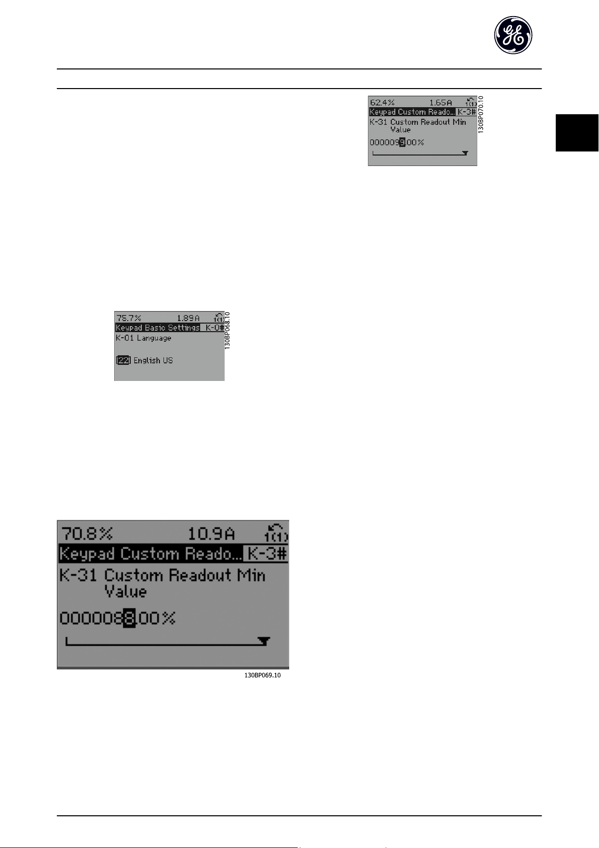
K-01 Language
Option: Function:
Defines the language to be used in the display.
The frequency converter is delivered with 4
different languages.
*
English
[0]
[2] Francais
[4] Spanish
[10] Chinese
[22] English US
K-02 Motor Speed Unit
Option: Function:
This parameter cannot be adjusted while the motor is
running.
The display showing depends on settings in
K-02 Motor Speed Unit and K-03 Regional Settings. The
default setting of K-02 Motor Speed Unit and
K-03 Regional Settings depends on which region of
the world the drive is supplied to, but can be reprogrammed as required.
NOTE
Changing the Motor Speed Unit will reset certain
parameters to their initial value. It is
recommended to select the motor speed unit
first, before modifying other parameters.
[0] RPM Selects display of motor speed variables and
parameters (i.e. references, feedbacks and limits) in
terms of motor speed (RPM).
*
Hz Selects display of motor speed variables and
[1]
parameters (i.e. references, feedbacks and limits) in
terms of output frequency to the motor (Hz).
K-03 Regional Settings
Option: Function:
This parameter cannot be adjusted while the
motor is running.
The display showing depends on settings in
K-02 Motor Speed Unit and K-03 Regional
Settings. The default setting of K-02 Motor
K-03 Regional Settings
Option: Function:
Speed Unit and K-03 Regional Settings depends
on which region of the world the frequency
converter is supplied to but can be reprogrammed as required.
[0] Interna-
tional
*
North
[1]
America
Sets P-07 Motor Power [kW] units to [kW] and
the default value of F-04 Base Frequency [50
Hz].
Sets P-02 Motor Power [HP] units to HP and the
default value of F-04 Base Frequency to 60 Hz.
The setting not used is made invisible.
K-04 Operating State at Power-up
Option: Function:
Select the operating mode upon reconnection
of the frequency converter to mains voltage
after power down when operating in Hand
(local)mode.
*
Resume Resumes operation of the frequency converter
[0]
maintaining the same local reference and the
same start/stop condition (applied by [Hand]/
[Off] on the keypad or Hand Start via a digital
input as before the frequency converter was
powered down.
[1] Forced
stop,
ref=old
Uses saved reference [1] to stop the frequency
converter but at the same time retain in
memory the local speed reference prior to
power down. After mains voltage is
reconnected and after receiving a start
command (using the keypad [Hand] button or
Hand Start command via a digital input) the
frequency converter restarts and operates at
the retained speed reference.
K-05 Local Mode Unit
Option: Function:
Defines if the local reference unit should
be displayed in terms of the motor shaft
speed (in RPM/Hz) or as percent.
*
As Motor Speed
[0]
Unit
[1] %
3.1.2 K-1# Keypad Set-up Operations
Define and control the individual parameter set-ups.
3
23
Page 25

Parameter Description AF-600 FP Programming Guide
3
The frequency converter has four parameter setups that
can be programmed independently of each other. This
makes the frequency converter very flexible and able to
meet the requirements of many different AF-600 FP system
control schemes often saving the cost of external control
equipment. For example these can be used to program the
frequency converter to operate according to one control
scheme in one setup (e.g. daytime operation) and another
control scheme in another setup (e.g. night set back).
Alternatively they can be used by an AHU or packaged
unit OEM to identically program all their factory fitted
frequency converters for different equipment models
within a range to have the same parameters and then
during production/commissioning simply select a specific
setup depending on which model within that range the
frequency converter is installed on.
The active setup (i.e. the setup in which the frequency
converter is currently operating) can be selected in
K-10 Active Set-up and is displayed in the keypad. Using
Multi set-up it is possible to switch between set-ups with
the frequency converter running or stopped, via digital
input or serial communication commands (e.g. for night
set back). If it is necessary to change setups whilst running,
ensure K-12 This Set-up Linked to is programmed as
required. For the majority of AF-600 FP applications it will
not be necessary to program K-12 This Set-up Linked to
even if change of set up whilst running is required, but for
very complex applications, using the full flexibility of the
multiple setups, it may be required. Using K-11 Edit Set-up
it is possible to edit parameters within any of the setups
whilst continuing the frequency converter operation in its
Active Setup which can be a different setup to that being
edited. Using K-51 Set-up Copy it is possible to copy
parameter settings between the set-ups to enable quicker
commissioning if similar parameter settings are required in
different set-ups.
K-10 Active Set-up
Option: Function:
Select the set-up in which the frequency
converter is to operate.
Use K-51 Set-up Copy to copy a set-up to one
or all other set-ups. To avoid conflicting
settings of the same parameter within two
different set-ups, link the set-ups together
using K-12 This Set-up Linked to. Stop the
frequency converter before switching between
set-ups where parameters marked ‘not
changeable during operation’ have different
values.
Parameters which are ‘not changeable during
operation’ are marked FALSE in the parameter
lists in the section Parameter Lists
[0] Factory
setup
Cannot be changed. It contains the GE data
set, and can be used as a data source when
returning the other set-ups to a known state.
K-10 Active Set-up
Option: Function:
[1] *Set-up 1 Set-up 1 [1] to Set-up 4 [4] are the four
separate parameter set-ups within which all
parameters can be programmed.
[2] Set-up 2
[3] Set-up 3
[4] Set-up 4
[9] Multi Set-upIs used for remote selection of set-ups using
digital inputs and the serial communication
port. This set-up uses the settings from
K-12 This Set-up Linked to.
K-11 Edit Set-up
Option: Function:
Select the set-up to be edited (i.e.
programmed) during operation; either the
active set-up or one of the inactive set-ups.
The set-up number being edited is displayed
in the keypad in (brackets).
[0] Factory
setup
[1] Set-up 1 Set-up 1 [1] to Set-up 4 [4] can be edited
[2] Set-up 2
[3] Set-up 3
[4] Set-up 4
*
Active Set-up(i.e. the set-up in which the frequency
[9]
cannot be edited but it is useful as a data
source to return the other set-ups to a
known state.
freely during operation, independently of the
active set-up.
converter is operating) can also be edited
during operation. Editing parameters in the
chosen setup would normally be done from
the keypad but it is also possible from any of
the serial communication ports.
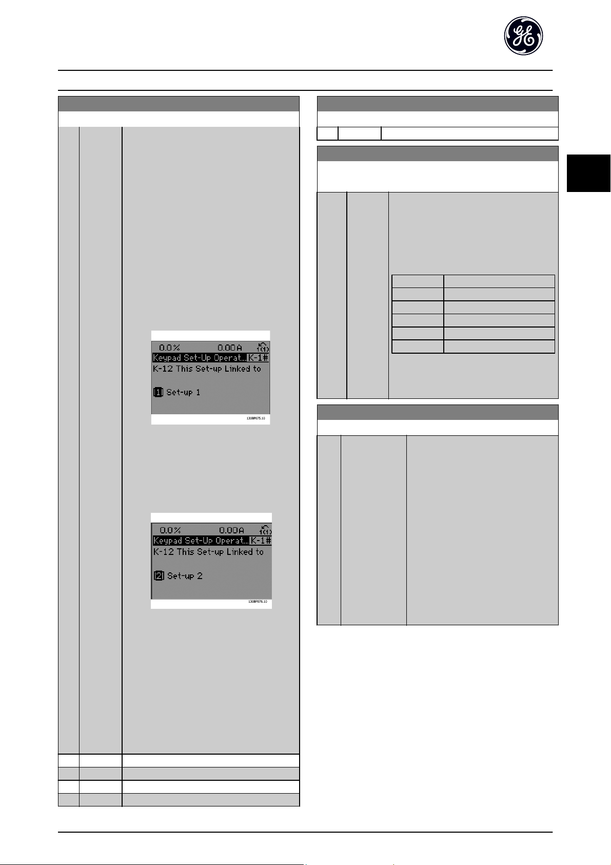
K-12 This Set-up Linked to
Option: Function:
This parameter only needs to be programmed if
changing set-ups is required whilst the motor is
running. It ensures that parameters which are
"not changeable during operation" have the
same setting in all relevant set-ups.
To enable conflict-free changes from one set-up
to another whilst the frequency converter is
running, link set-ups containing parameters
which are not changeable during operation.
The link will ensure synchronising of the ‘not
changeable during operation’ parameter values
when moving from one set-up to another
during operation. ‘Not changeable during
operation’ parameters can be identified by the
label FALSE in the parameter lists in the section
Parameter Lists.
24
Page 26
Parameter Description AF-600 FP Programming Guide
3
K-12 This Set-up Linked to
Option: Function:
The K-12 This Set-up Linked to feature is used
when Multi set-up in K-10 Active Set-up is
selected. Multi set-up can be used to move
from one set-up to another during operation
(i.e. while the motor is running).
Example:
Use Multi set-up to shift from Set-up 1 to Setup 2 whilst the motor is running. Programme
parameters in Set-up 1 first, then ensure that
Set-up 1 and Set-up 2 are synchronised (or
‘linked’). Synchronisation can be performed in
two ways:
1. Change the edit set-up to Set-up 2 [2] in
K-11 Edit Set-up and set K-12 This Set-up Linked
to to Set-up 1 [1]. This will start the linking
(synchronising) process.
K-12 This Set-up Linked to
Option: Function:
[4] Set-up 4
K-13 Readout: Linked Set-ups
Array [5]
Range: Function:
0 N/A* [0 - 255
N/A]
View a list of all the set-ups linked by means
of K-12 This Set-up Linked to. The parameter
has one index for each parameter set-up. The
parameter value displayed for each index
represents which setups are linked to that
parameter setup.
Index keypad value
0 {0}
1 {1,2}
2 {1,2}
3{3}
4 {4}
Table 3.2 Example: Set-up 1 and Set-up 2
are linked
3
*
Not linked
[0]
[1] Set-up 1
[2] Set-up 2
[3] Set-up 3
OR
2. While still in Set-up 1, using K-50 Keypad
Copy, copy Set-up 1 to Set-up 2. Then set
K-12 This Set-up Linked to to Set-up 2 [2]. This
will start the linking process.
After the link is complete, K-13 Readout: Linked
Set-ups will read {1,2} to indicate that all ‘not
changeable during operation’ parameters are
now the same in Set-up 1 and Set-up 2. If there
are changes to a ‘not changeable during
operation’ parameter, e.g. P-30 Stator Resistance
(Rs), in Set-up 2, they will also be changed
automatically in Set-up 1. A switch between
Set-up 1 and Set-up 2 during operation is now
possible.
K-14 Readout: Edit Set-ups / Channel
Range: Function:
0 N/
[-2147483648 -
A
2147483647 N/
*
A]
View the setting of K-11 Edit Set-up for
each of the four different communication channels. When the number is
displayed in hex, as it is in the keypad,
each number represents one channel.
Numbers 1-4 represent a set-up number;
‘F’ means factory setting; and ‘A’ means
active set-up. The channels are, from
right to left: keypad, Drive-bus, USB,
HPFB1.5.
Example: The number AAAAAA21h
means that the Drive-bus selected Setup 2 in K-11 Edit Set-up, the keypad
selected Set-up 1 and all others used
the active set-up.
25
Page 27
Parameter Description AF-600 FP Programming Guide
3
3.1.3 K-2# Keypad Display
Define the variables displayed in the keypad.
[0] *None No display value selected
[537] Display Text 1 Enables an individual text string to be
written, for display in the keypad or
to be read via serial communication.
[538] Display Text 2 Enables an individual text string to be
written, for display in the keypad or
to be read via serial communication.
[539] Display Text 3 Enables an individual text string to be
written, for display in the keypad or
to be read via serial communication.
[589] Date and Time
Readout
[953] Profibus Warning
Word
[2205] Readout Transmit
Error Counter
[2206] Readout Receive
Error Counter
[2207] Readout Bus Off
Counter
[2213] Warning
Parameter
[1501] Running Hours View the number of running hours of
[1502] kWh Counter View the mains power consumption
[1200] Control Word View the Control Word sent from the
[1201] Reference [Unit] Total reference (sum of digital/analog/
[1202] Reference [%] Total reference (sum of digital/analog/
[1203] Status Word Present status word
[1205] Main Actual Value
[%]
[1209] Custom Readout View the user-defined readouts as
[1210] Power [kW] Actual power consumed by the motor
[1211] Power [hp] Actual power consumed by the motor
[1212] Motor Rated
Voltage
Displays the current date and time.
Displays Profibus communication
warnings.
View the number of CAN control
transmission errors since the last
power-up.
View the number of CAN control
receipt errors since the last power-up.
View the number of Bus Off events
since the last power-up.
View a DeviceNet-specific warning
word. One separate bit is assigned to
every warning.
the motor.
in kWh.
frequency converter via the serial
communication port in hex code.
preset/bus/freeze ref./catch up and
slow-down) in selected unit.
preset/bus/freeze ref./catch up and
slow-down) in percent.
View the two-byte word sent with the
Status word to the bus Master
reporting the Main Actual Value.
defined in K-30 Unit for Custom
Readout, K-31 Min Value of Custom
Readout and K-32 Max Value of
Custom Readout.
in kW.
in HP.
Voltage supplied to the motor.
[1213] Frequency Motor frequency, i.e. the output
frequency from the frequency
converter in Hz
[1214] Motor Current Phase current of the motor measured
as effective value.
[1215] Frequency [%] Motor frequency, i.e. the output
frequency from the frequency
converter in percent.
[1216] Torque [Nm] Present motor load as a percentage
of the rated motor torque.
[1217] Speed [RPM] Motor speed reference. Actual speed
will depend on slip compensation
being used (compensation set in
P-09 Slip Compensation). If not used,
actual speed will be the value read in
the display minus motor slip.
[1218] Motor Thermal Thermal load on the motor,
calculated by the Electronic Thermal
Overload function. See also parameter
group H-9# Motor Temperature.
[1222] Torque [%] Shows the actual torque produced, in
percentage.
[1230] DC Link Voltage Intermediate circuit voltage in the
frequency converter.
[1232] Brake Energy /s Present brake power transferred to an
external brake resistor. Stated as an
instantaneous value.
[1233] Brake Energy /2
min
[1234] Heatsink Temp. Present heat sink temperature of the
[1235] Drive Thermal Percentage load of the inverters.
[1236] Drive Nominal
Current
[1237] Drive Max.
Current
[1238] Logic Controller
State
[1239] Control Card
Temp.
[1250] External Reference Sum of the external reference as a
[1252] Feedback [Unit] Reference value from programmed
[1253] Digi Pot
Reference
[1254] Feedback 1 [Unit] View the value of Feedback 1. See
[1255] Feedback 2 [Unit] View the value of Feedback 2. See
Brake power transferred to an
external brake resistor. The mean
power is calculated continuously for
the most recent 120 seconds.
frequency converter. The cut-out limit
± 5°
is 95
70
Nominal current of the frequency
converter.
Maximum current of the frequency
converter.
State of the event executed by the
control.
Temperature of the control card.
percentage, i.e. the sum of analog/
pulse/bus.
digital input(s).
View the contribution of the digital
potentiometer to the actual reference
Feedback.
also par. CL-0#.
also par. CL-0#.
C; cutting back in occurs at
± 5°
C.
26
Page 28
Parameter Description AF-600 FP Programming Guide
3
[1256] Feedback 3 [Unit] View the value of Feedback 3. See
also par. CL-0#.
[1258] PID Output [%] Returns the Drive Closed Loop PID
controller output value in percent.
[1260] Digital Input Displays the status of the digital
inputs. Signal low = 0; Signal high =
1.
Regarding order, see DR-60 Digital
Input. Bit 0 is at the extreme right.
[1261] Terminal 53
Switch Setting
[1262] Analog Input 53 Actual value at input 53 either as a
[1263] Terminal 54
Switch Setting
[1264] Analog Input 54 Actual value at input 54 either as
[1265] Analog Output 42
[mA]
[1266] Digital Output
[bin]
[1267] Freq. Input #29
[Hz]
[1268] Freq. Input #33
[Hz]
[1269] Pulse Output #27
[Hz]
[1270] Pulse Output #29
[Hz]
[1271] Relay Output [bin] View the setting of all relays.
[1272] Counter A View the present value of Counter A.
[1273] Counter B View the present value of Counter B.
[1275] Analog In X30/11 Actual value at input X30/11 either as
[1276] Analog In X30/12 Actual value at input X30/12 either as
[1277] Analog Out X30/8
[mA]
[1280] Fieldbus CTW 1 Control word (CTW) received from the
[1282] Fieldbus REF 1 Main reference value sent with
[1284] Comm. Option
STW
[1285] Drive Port CTW 1 Control word (CTW) received from the
[1286] Drive Port REF 1 Status word (STW) sent to the Bus
[1290] Alarm Word One or more alarms in a Hex code
Setting of input terminal 53. Current
= 0; Voltage = 1.
reference or protection value.
Setting of input terminal 54. Current
= 0; Voltage = 1.
reference or protection value.
Actual value at output 42 in mA. Use
AN-50 Terminal 42 Output to select
the variable to be represented by
output 42.
Binary value of all digital outputs.
Actual value of the frequency applied
at terminal 29 as a pulse input.
Actual value of the frequency applied
at terminal 33 as a pulse input.
Actual value of pulses applied to
terminal 27 in digital output mode.
Actual value of pulses applied to
terminal 29 in digital output mode.
reference or protection value.
reference or protection value.
Actual value at output X30/8 in mA.
Use par. AN-60 to select the value to
be shown.
Bus Master.
control word via the serial communications network e.g. from the BMS,
PLC or other master controller.
Extended fieldbus communication
option status word.
Bus Master.
Master.
(used for serial communications)
[1291] Alarm Word 2 One or more alarms in a Hex code
(used for serial communications)
[1292] Warning Word One or more warnings in a Hex code
(used for serial communications)
[1293] Warning Word 2 One or more warnings in a Hex code
(used for serial communications)
[1294] Ext. Status Word One or more status conditions in a
Hex code (used for serial communications)
[1295] Ext. Status Word 2 One or more status conditions in a
Hex code (used for serial communications)
[1296] Maintenance
Word
[1830] Analog Input
X42/1
[1831] Analog Input
X42/3
[1832] Analog Input
X42/5
[1833] Analog Out X42/7
[V]
[1834] Analog Out X42/9
[V]
[1835] Analog Out
X42/11 [V]
[2117] Ext. 1 Reference
[Unit]
[2118] Ext. 1 Feedback
[Unit]
[2119] Ext. 1 Output [%] The value of the output from
[2137] Ext. 2 Reference
[Unit]
[2138] Ext. 2 Feedback
[Unit]
[2139] Ext. 2 Output [%] The value of the output from
[2157] Ext. 3 Reference
[Unit]
[2158] Ext. 3 Feedback
[Unit]
[2159] Ext. 3 Output [%] The value of the output from
[1230] No-Flow Power The calculated No Flow Power for the
[2316] Maintenance Text
[2580] Pump Status
The bits reflect the status for the
programmed Preventive Maintenance
Events in parameter group T-1#
Shows the value of the signal applied
to terminal X42/1 on the Analog I/O
card.
Shows the value of the signal applied
to terminal X42/3 on the Analog I/O
card.
Shows the value of the signal applied
to terminal X42/5 on the Analog I/O
card.
Shows the value of the signal applied
to terminal X42/7 on the Analog I/O
card.
Shows the value of the signal applied
to terminal X42/9 on the Analog I/O
card.
Shows the value of the signal applied
to terminal X42/11 on the Analog I/O
card.
The value of the reference for
extended Closed Loop Controller 1
The value of the feedback signal for
extended Closed Loop Controller 1
extended Closed Loop Controller 1
The value of the reference for
extended Closed Loop Controller 2
The value of the feedback signal for
extended Closed Loop Controller 2
extended Closed Loop Controller 2
The value of the reference for
extended Closed Loop Controller 3
The value of the feedback signal for
extended Closed Loop Controller 3
extended Closed Loop Controller 3
actual operating speed
3
27
Page 29
Parameter Description AF-600 FP Programming Guide
3
[2581] Pump Status Status for the operation of each
individual pump controlled by the
Pump Controller.
K-20 Display Line 1.1 Small
Option: Function:
Select a variable for display in line 1, left position.
The options are the same as those listed under K-2#.
K-21 Display Line 1.2 Small
Option: Function:
Select a variable for display in line 1, middle position.
The options are the same as those listed under K-2#.
K-22 Display Line 1.3 Small
Option: Function:
Select a variable for display in line 1, right position.
The options are the same as those listed under K-2#.
K-23 Display Line 2 Large
Option: Function:
Select a variable for display in line 2.
The options are the same as those listed under K-2#.
K-24 Display Line 3 Large
Option: Function:
Select a variable for display in line 3.
The options are the same as those listed under K-2#.
K-25 Quick Start
Array [20]
Range: Function:
0 N/
[0 -
A
9999 N/
*
A]
Define up to 50 parameters to appear in the Q1
Quick Start, accessible via the [Quick Menu] key
on the keypad. The parameters will be displayed
in the Q1 Quick Start in the order they are
programmed into this array parameter. Delete
parameters by setting the value to ‘0000’.
For example, this can be used to provide quick,
simple access to just one or up to 50
parameters which require changing on a regular
basis (e.g. for plant maintenance reasons) or by
an OEM to enable simple commissioning of
their equipment.
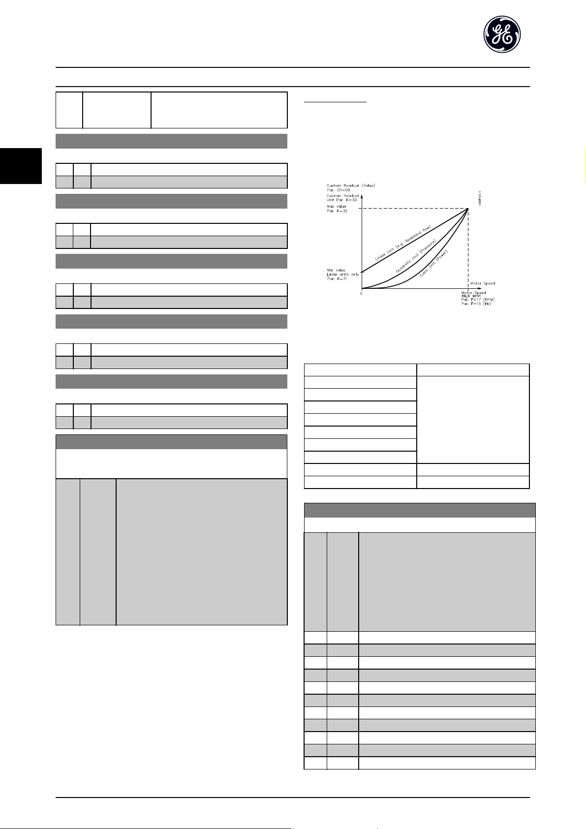
3.1.4 K-3# Keypad Custom Readout
It is possible to customize the display elements for various
purposes: *Custom Readout. Value proportional to speed
(Linear, squared or cubed depending on unit selected in
K-30 Unit for Custom Readout) *Display Text. Text string
stored in a parameter.
Custom Readout
The calculated value to be displayed is based on settings
in K-30 Unit for Custom Readout, K-31 Min Value of Custom
Readout (linear only), K-32 Max Value of Custom Readout,
F-17 Motor Speed High Limit [RPM], F-15 Motor Speed High
Limit [Hz] and actual speed.
The relation will depend on the type of unit selected in
K-30 Unit for Custom Readout:
Unit Type Speed Relation
Dimensionless
Speed
Flow, volume
Flow, mass
Velocity
Length
Temperature
Pressure Quadratic
Power Cubic
Linear
K-30 Unit for Custom Readout
Option: Function:
Program a value to be shown in the display of
the keypad. The value has a linear, squared or
cubed relation to speed. This relation depends on
the unit selected (see table above). The actual
calculated value can be read in DR-09 Custom
Readout, and/or shown in the display be selecting
Custom Readout [DR-09] in K-20 Display Line 1.1
Small to K-24 Display Line 3 Large.
[0]
*
%
[1]
[5] PPM
[10] 1/min
[11] RPM
[12] Pulse/s
[20] l/s
[21] l/min
[22] l/h
[23] m/s
[24] m/min
28
Page 30

Parameter Description AF-600 FP Programming Guide
3
K-30 Unit for Custom Readout
Option: Function:
[25] m/h
[30] kg/s
[31] kg/min
[32] kg/h
[33] t/min
[34] t/h
[40] m/s
[41] m/min
[45] m
[60] °C
[70] mbar
[71] bar
[72] Pa
[73] kPa
[74] m WG
[75] mm Hg
[80] kW
[120] GPM
[121] gal/s
[122] gal/min
[123] gal/h
[124] CFM
[125] ft/s
[126] ft/min
[127] ft/h
[130] lb/s
[131] lb/min
[132] lb/h
[140] ft/s
[141] ft/min
[145] ft
[160] °F
[170] psi
[171] lb/in
[172] in WG
[173] ft WG
[174] in Hg
[180] HP
K-31 Min Value of Custom Readout
Range: Function:
0.00 CustomReadoutUnit
[0.00 - par. K-32
CustomRea-
*
doutUnit]
This parameter allows the
choice of the min. value of
the custom defined readout
(occurs at zero speed). It is
only possible to select a
value different to 0 when
selecting a linear unit in
K-30 Unit for Custom Readout.
For Quadratic and Cubic
units the minimum value will
be 0.
K-32 Max Value of Custom Readout
Range: Function:
100.00 CustomReadoutUnit
*
[par. K-31 -
999999.99
CustomReadoutUnit]
This parameter sets the
max value to be shown
when the speed of the
motor has reached the set
value for F-17 Motor Speed
High Limit [RPM] or
F-15 Motor Speed High Limit
[Hz] (depends on setting in
K-02 Motor Speed Unit).
K-37 Display Text 1
Range: Function:
0 N/
[0 -
In this parameter it is possible to write an
A
0 N/
*
individual text string for display in the keypad or to
A]
be read via serial communication. If to be displayed
permanently select Display Text 1 in K-20 Display
Line 1.1 Small, K-21 Display Line 1.2 Small,
K-22 Display Line 1.3 Small, K-23 Display Line 2 Large
or K-24 Display Line 3 Large. Use the [
buttons on the keypad to change a character. Use
the [◀] and [▶] buttons to move the cursor. When
a character is highlighted by the cursor, it can be
changed. Use the [▲] or [▼] buttons on the keypad
to change a character. A character can be inserted
by placing the cursor between two characters and
pressing [
] or [▼].
▲
K-38 Display Text 2
Range: Function:
0 N/
[0 -
In this parameter it is possible to write an
A
0 N/
*
individual text string for display in the keypad or
A]
to be read via serial communication. If to be
displayed permanently select Display Text 2 in
K-20 Display Line 1.1 Small, K-21 Display Line 1.2
Small, K-22 Display Line 1.3 Small, K-23 Display Line
2 Large or K-24 Display Line 3 Large. Use the [
] buttons on the keypad to change a character.
[
▼
Use the [
When a character is highlighted by the cursor, this
character can be changed. A character can be
inserted by placing the cursor between two
characters and pressing [
] and [▶] buttons to move the cursor.
◀
] or [▼].
▲
] or [▼]
▲
3
] or
▲
29
Page 31

Parameter Description AF-600 FP Programming Guide
3
K-39 Display Text 3
Range: Function:
0 N/
[0 -
In this parameter it is possible to write an
A
0 N/
*
individual text string for display in the keypad or to
A]
be read via serial communication. If to be displayed
permanently select Display Text 3 in K-20 Display
Line 1.1 Small,K-21 Display Line 1.2 Small,
K-22 Display Line 1.3 Small, K-23 Display Line 2 Large
or K-24 Display Line 3 Large. Use the [
buttons on the keypad to change a character. Use
the [
] and [▶] buttons to move the cursor. When
◀
a character is highlighted by the cursor, this
character can be changed. A character can be
inserted by placing the cursor between two
characters and pressing [
] or [▼].
▲
] or [▼]
▲
3.1.5 K-4# Keypad Buttons
Enable, disable and password protect individual keys on
the keypad.
K-40 [Hand] Button on Keypad
Option: Function:
[0] Disabled No function
*
Enabled [Hand ] Key enabled
[1]
[2] Password
Protection
Avoid unauthorized start in Hand mode. If
K-40 [Hand] Button on Keypadis included
in the Quick Start Menu, then define the
password in K-65 Quick Menu Password.
Otherwise define the password in
K-60 Main Menu Password.
K-42 [Auto] Button on Keypad
Option: Function:
Otherwise define the password in
K-60 Main Menu Password.
K-43 [Reset] Button on Keypad
Option: Function:
[0] Disabled No function
*
Enabled [Reset] Key is enabled
[1]
[2] Password
Protection
Avoid unauthorized resetting. If
K-43 [Reset] Button on Keypad is included
in the K-25 Quick Start, then define the
password in K-65 Quick Menu Password.
Otherwise define the password in
K-60 Main Menu Password.
K-41 [Off] Button on Keypad
Option: Function:
[0] Disabled No function
*
Enabled [Off] Key is enabled
[1]
[2] Password
Protection
Avoid unauthorized stop. If K-41 [Off]
Button on Keypad is included in the Quick
Start Menu, then define the password in
K-65 Quick Menu Password. Otherwise
define the password in K-60 Main Menu
Password.
K-42 [Auto] Button on Keypad
Option: Function:
[0] Disabled No function
*
Enabled [Auto ] Key is enabled
[1]
[2] Password
Protection
Avoid unauthorized start in Auto mode. If
K-42 [Auto] Button on Keypad is included in
the Quick Start Menu, then define the
password in K-65 Quick Menu Password.
30
Page 32

Parameter Description AF-600 FP Programming Guide
3
3.1.6 K-5# Copy / Save
Copy parameter settings between set-ups and to/from the
keypad.
K-50 Keypad Copy
Option: Function:
[0] *No copy No function
[1] All to
Keypad
[2] All from
Keypad
[3] Size indep.
From
Keypad
Copies all parameters in all set-ups from the
frequency converter memory to the keypad
memory. For service purposes it is
recommended to copy all parameters to the
keypad after commissioning.
Copies all parameters in all set-ups from the
keypad memory to the frequency converter
memory.
Copies only the parameters that are
independent of the motor size. The latter
selection can be used to programme several
frequency converters with the same function
without disturbing motor data which are
already set.
This parameter cannot be adjusted while the motor is
running.
K-51 Set-up Copy
Option: Function:
[0] *No copy No function
[1] Copy to set-
up 1
[2] Copy to set-
up 2
[3] Copy to set-
up 3
[4] Copy to set-
up 4
[9] Copy to all Copies the parameters in the present set-up
Copies all parameters in the present
Programming Set-up (defined in K-11 Edit
Set-up) to Set-up 1.
Copies all parameters in the present
Programming Set-up (defined in K-11 Edit
Set-up) to Set-up 2.
Copies all parameters in the present
Programming Set-up (defined in K-11 Edit
Set-up) to Set-up 3.
Copies all parameters in the present
Programming Set-up (defined in K-11 Edit
Set-up) to Set-up 4.
over to each of the set-ups 1 to 4.
3.1.7 K-6# Password Protection
K-61 Access to Main Menu w/o Password
Option: Function:
[0] *Full access Disables password defined in K-60 Main Menu
Password.
[1] Read only Prevent unauthorized editing of Main Menu
parameters.
[2] No access Prevent unauthorized viewing and editing of
Main Menu parameters.
If Full access [0] is selected then K-60 Main Menu Password,
K-65 Quick Menu Password and K-66 Access to Quick Menu
w/o Password will be ignored.
K-65 Quick Menu Password
Range: Function:
200 N/A* [0 - 999
N/A]
Define the password for access to the
Quick Start Menu via the [Quick Menu]
key. If K-66 Access to Quick Menu w/o
Password is set to Full access [0], this
parameter will be ignored.
K-66 Access to Quick Menu w/o Password
Option: Function:
[0] *Full access Disables password defined in K-65 Quick Menu
Password.
[1] Read only Prevents unauthorized editing of Quick Start
Menu parameters.
[2] No access Prevents unauthorized viewing and editing of
Quick Start Menu parameters.
If K-61 Access to Main Menu w/o Password is set to Full
access [0], this parameter will be ignored.
3.1.8 K-7# Clock Settings
Set the time and date of the internal clock. The internal
clock can be used for e.g. Timed Actions, energy log, Trend
Analysis, date/time stamps on alarms, Logged data and
Preventive Maintenance.
It is possible to program the clock for Daylight Saving
Time / summertime, weekly working days/non-working
days including 20 exceptions (holidays etc.). Although the
clock settings can be set via the keypad, they can also be
set along with timed actions and preventative
maintenance functions using the DCT10 software tool.
3
K-60 Main Menu Password
Range: Function:
100 N/A* [0 - 999
N/A]
Define the password for access to the
Main Menu via the [Main Menu] key. If
K-61 Access to Main Menu w/o Password is
set to Full access [0], this parameter will
be ignored.
31
Page 33

Parameter Description AF-600 FP Programming Guide
3
NOTE
The frequency converter has no back up of the clock
function and the set date/time will reset to default
(2000-01-01 00:00) after a power down unless the OPCAIO
Analog Option Module or OPC24VPS 24V DC External
Supply Option Module is installed. If no module with back
up is installed, it is recommended the clock function is
only used if the frequency converter is integrated into the
BMS using serial communications, with the BMS
maintaining synchronization of control equipment clock
times. In K-79 Clock Fault it is possible to program for a
Warning in case clock has not been set properly, e.g. after
a power down.
NOTE
If mounting an OPCAIO option card, a battery back-up of
the date and time is included.
K-70 Date and Time
Range: Function:
0 N/A
*
K-71 Date Format
Option: Function:
[0] YYYY-MM-DD
[1] DD-MM-YYYY
*
MM/DD/YYYY
[2]
K-72 Time Format
Option: Function:
[0] 24 h
*
12 h
[1]
K-74 DST/Summertime
Option: Function:
*
Off
[0]
[2] Manual
[0 - 0 N/A]
Sets the date format to be used in the
keypad.
Sets the time format to be used in the keypad.
Choose how Daylight Saving Time/Summertime
should be handled. For manual DST/Summertime
enter the start date and end date in K-76 DST/
Summertime Start and K-77 DST/Summertime End.
K-79 Clock Fault
Option: Function:
Enables or disables the clock warning, when the
clock has not been set or has been reset due to a
power-down and no backup is installed. If
OPCAIO is installed “enabled” is default
*
Disabled
[0]
[1] Enabled
3.1.9 K-8# Days and Date/Time Readout
K-81 Working Days
Array with 7 elements [0] - [6] displayed below parameter
number in display. Press OK and step between elements by
means of
Option: Function:
*
[0]
[1] Yes
K-82 Additional Working Days
Array with 5 elements [0] - [4] displayed below parameter
number in display. Press OK and step between elements by
means of
Range: Function:
0 N/A
K-83 Additional Non-Working Days
Array with 15 elements [0] - [14] displayed below parameter
number in display. Press OK and step between elements by
means of
Range: Function:
0 N/A
and ▼ buttons on the keypad.
▲
Set for each weekday if it is a working day or a nonworking day. First element of the array is Monday.
The working days are used for Timed Actions.
No
and▼ buttons on the keypad.
▲
*
*
[0 - 0 N/A] Defines dates for additional
working days that normally
would be non-working days
according to K-81 Working
Days.
and▼ buttons on the keypad.
▲
[0 - 0 N/A] Defines dates for additional
working days that normally
would be non-working days
according to K-81 Working
Days.
K-76 DST/Summertime Start
Range: Function:
0 N/A* [0 - 0 N/A] Sets the date and time when summertime/
DST starts. The date is programmed in the
format selected in K-71 Date Format.
K-77 DST/Summertime End
Range: Function:
0 N/A
*
32
[0 - 0 N/A]
K-89 Date and Time Readout
Range: Function:
0 N/A* [0 - 0 N/A] Displays the current date and time. The
date and time is updated continuously.
The clock will not begin counting until a
setting different from default has been
made in K-70 Date and Time.
Page 34

Parameter Description AF-600 FP Programming Guide
3
3.2 F-## Fundamental Parameters
3.2.1 F-0# Fundamental Parameters
F-01 Frequency Setting 1
Option: Function:
Select the reference input to be used
for the first reference signal.
F-01 Frequency Setting 1,
C-30 Frequency Command 2 and
C-34 Frequency Command 3 define
up to three different reference
signals. The sum of these reference
signals defines the actual reference.
This parameter cannot be adjusted
while the motor is running.
[0] No function
*
Analog input 53
[1]
[2] Analog input 54
[7] Pulse input 29
[8] Pulse input 33
[20] Digital Potentiometer
[21] Analog input X30/11 (OPCGPIO)
[22] Analog input X30/12 (OPCGPIO)
[23] Analog Input X42/1 (OPCAIO)
[24] Analog Input X42/3 (OPCAIO)
[25] Analog Input X42/5 (OPCAIO)
[30] Ext. Closed Loop 1
[31] Ext. Closed Loop 2
[32] Ext. Closed Loop 3
F-02 Operation Method
Option: Function:
Select which reference site to activate.
*
Linked to
[0]
Hand / Auto
[1] Remote Use remote reference in both Hand mode
[2] Local Use local reference in both Hand mode and
Use local reference when in Hand mode; or
remote reference when in Auto mode.
and Auto mode.
Auto mode.
NOTE
When set to Local [2], the drive will start
with this setting again following a
'power down'.
F-03 Max Output Frequency 1
Range: Function:
120.0
Hz
*
[1.0 -
1000.0 Hz]
Enter the maximum output frequency
value. F-03 Max Output Frequency 1
specifies the absolute limit on the
frequency converter output frequency for
improved safety in applications where
accidental over-speeding must be avoided.
This absolute limit applies to all configurations and is independent of the setting
in H-40 Configuration Mode. This parameter
cannot be adjusted while the motor is
running.
F-04 Base Frequency
Range: Function:
60. Hz* [20 - 1000 Hz] Select the motor frequency value from
the motor nameplate data.
NOTE
This parameter cannot be adjusted while the motor is
running.
F-05 Motor Rated Voltage
Range: Function:
400. V* [10. - 1000.V]Enter the nominal motor voltage
according to the motor nameplate data.
The default value corresponds to the
nominal rated output of the unit.
This parameter cannot be adjusted while
the motor is running.
F-07 Accel Time 1
Range: Function:
10.00 s* [1.00 -
3600.00 s]
par. F
− 07 =
Enter the accel time, i.e. the acceleration
time from 0 RPM to P-06 Base Speed.
Choose a accel time such that the
output current does not exceed the
current limit in F-43 Current Limit during
ramping. See decel time in F-08 Decel
Time 1.
t
acc
×
n
norm
par.P
− 06
ref rpm
s
3
33
Page 35

Parameter Description AF-600 FP Programming Guide
3
F-08 Decel Time 1
Range: Function:
20.00 s* [1.00 -
3600.00 s]
par. F
− 08 =
Enter the decel time, i.e. the deceleration
time from P-06 Base Speed to 0 RPM.
Choose a decel time such that no overvoltage arises in the inverter due to
regenerative operation of the motor, and
such that the generated current does not
exceed the current limit set in F-43 Current
Limit. See accel time in F-07 Accel Time 1.
t
dec
×
n
norm
par.P
− 06
ref rpm
s
3.2.2 F-1# Fundamental Parameters 1
F-10 Electronic Overload
Option: Function:
The frequency converter determines the
motor temperature for motor protection
in two different ways:
Via a thermistor sensor
•
connected to one of the analog
or digital inputs (F-12 Motor
Thermistor Input).
Via calculation of the thermal
•
load, based on the actual load
and time. The calculated thermal
load is comed with the rated
motor current I
motor frequency f
calculations estimate the need
for a lower load at lower speed
due to less cooling from the fan
incorporated in the motor.
[0] No protection If the motor is continuously overloaded
and no warning or trip of frequency
converter is wanted.
[1] Thermistor
warning
[2] Thermistor trip Stops (trips) the frequency converter
[3] Elec. OL
Warning 1
*
Elec. OL Trip 1
[4]
[5] Elec. OL
Warning 2
[6] Elec. OL Trip 2
[7] Elec. OL
Warning 3
[8] Elec. OL Trip 3
Activates a warning when the connected
thermistor in the motor reacts in the
event of motor over-temperature.
when the connected thermistor in the
motor reacts in the event of motor overtemperature.
and the rated
M,N
. The
M,N
F-10 Electronic Overload
Option: Function:
[9] Elec. OL
Warning 4
[10] Elec. OL Trip 4
Electronic Overload functions 1-4 will calculate the load
when set-up where they were selected is active. For
example Elec. OL Warning 3 or Trip 3 starts calculating
when set-up 3 is selected. For the North American market:
The Electronic Overload functions provide class 20 motor
overload protection in accordance with NEC.
WARNING
In order to maintain PELV, all connections made to the
control terminals must be PELV, e.g. thermistor must be
reinforced/ double insulated
F-11 Motor External Fan
Option: Function:
[0] *No No external fan on motor, i.e. the motor is derated at
low speed.
[1] Yes Applies an external motor fan (external ventilation), so
no derating of the motor is required at low speed. The
upper curve in graph above (fout = 1 x fM,N) is
followed if the motor current is lower than nominal
motor current (see P-03 Motor Current). If the motor
current exceeds nominal current, the operation time
still decreases as if no fan were installed.
34
Page 36

Parameter Description AF-600 FP Programming Guide
3
F-12 Motor Thermistor Input
Option: Function:
Select the input to which the thermistor
(PTC sensor) should be connected. An
analog input option [1] or [2] cannot be
selected if the analog input is already in
use as a reference source (selected in
F-01 Frequency Setting 1, C-30 Frequency
Command 2 or C-34 Frequency Command
3).
*
None
[0]
[1] Analog input 53
[2] Analog input 54
[3] Digital input 18
[4] Digital input 19
[5] Digital input 32
[6] Digital input 33
NOTE
This parameter cannot be adjusted while the motor is
running.
NOTE
Digital input should be set to [0] PNP - Active at 24V in .
E-0#.
F-17 Motor Speed High Limit [RPM]
Range: Function:
in the Main Menu and depending on
default settings dependant on global
location.
NOTE
Max. output frequency cannot exceed 10% of the carrier
frequency (F-26 Motor Noise (Carrier Freq)).
NOTE
Any changes in F-17 Motor Speed High Limit [RPM] will reset
the value in H-73 Warning Speed High to the same value as
set in F-17 Motor Speed High Limit [RPM].
F-18 Motor Speed Low Limit [RPM]
Range: Function:
0 RPM* [0 - par.
F-17 RPM]
Enter the minimum limit for motor speed.
The Motor Speed Low Limit can be set to
correspond to the manufacturer’s
recommended minimum motor speed. The
Motor Speed Low Limit must not exceed
the setting in F-17 Motor Speed High Limit
[RPM].
3
F-15 Motor Speed High Limit [Hz]
Range: Function:
50/60.0 Hz
*
[par. F-16 - par. F-03 Hz]
NOTE
Max. output frequency cannot exceed 10% of the carrier
frequency (F-26 Motor Noise (Carrier Freq)).
F-16 Motor Speed Low Limit [Hz]
Range: Function:
0 Hz* [0 - par.
F-15 Hz]
F-17 Motor Speed High Limit [RPM]
Range: Function:
1800.
RPM
*
[par. F-18
- 60000.
RPM]
Enter the minimum limit for motor speed.
The Motor Speed Low Limit can be set to
correspond to the minimum output
frequency of the motor shaft. The Speed
Low Limit must not exceed the setting in
F-15 Motor Speed High Limit [Hz].
Enter the maximum limit for motor speed.
The Motor Speed High Limit can be set to
correspond to the manufacturer’s
maximum rated motor. The Motor Speed
High Limit must exceed the setting in
F-18 Motor Speed Low Limit [RPM]. Only
F-18 Motor Speed Low Limit [RPM] or
F-16 Motor Speed Low Limit [Hz] will be
displayed depending on other parameters
3.2.3 F-2# Fundamental Parameters 2
F-24 Holding Time
Range: Function:
0.0 s* [0.0 - 120.0s]The function selected in H-80 Function at
Stop is active in the delay period.
Enter the time delay required before
commencing acceleration.
F-26 Motor Noise (Carrier Freq)
Option: Function:
Select the carrier frequency. Changing the carrier
frequency can help to reduce acoustic noise from
the motor.
Switching frequencies higher than 5.0 kHz lead to
automatic derating of the maximum output of
the frequency converter.
[0] 1.0 kHz
[1] 1.5 kHz
[2] 2.0 kHz
[3] 2.5 kHz
[4] 3.0 kHz
[5] 3.5 kHz
[6] 4.0 kHz
*
5.0 kHz
[7]
[8] 6.0 kHz
[9] 7.0 kHz
35
Page 37

Parameter Description AF-600 FP Programming Guide
3
F-26 Motor Noise (Carrier Freq)
Option: Function:
[10] 8.0 kHz
[11] 10.0 kHz
[12] 12.0 kHz
[13] 14.0 kHz
[14] 16.0 kHz
F-27 Motor Tone Random
Option: Function:
[0] *Off No change of the acoustic motor switching noise.
[1] On Transforms the acoustic motor switching noise from a
clear ringing tone to a less noticeable ‘white’ noise.
This is achieved by slightly and randomly altering the
synchronism of the pulse width modulated output
phases.
3.2.4 F-3# Fundamental Parameters 3
F-37 Adv. Switching Pattern
Option: Function:
Select the switching pattern: 60° AVM or SFAVM.
*
60 AVM
[0]
[1] SFAVM
NOTE
Enabling over-modulation can cause vibrations that may
destroy the mechanics if running in field weakening ares
(from 47Hz).
F-38 Overmodulation
Option: Function:
[0] Off Selects no over-modulation of the output voltage in
order to avoid torque ripple on the motor shaft.
*
On The over-modulation function generates an extra
[1]
voltage of up-to 8% of U
over-modulation, which results in an extra torque of
10-12% in the middle of the over-syncronous range
(from 0% at nominal speed rising to approximately
12% at double nominal speed).
output voltage without
max
F-40 Torque Limiter (Driving)
Range: Function:
See also SP-25 Trip Delay at Torque Limit for
further details.
F-41 Torque Limiter (Braking)
Range: Function:
100.0 %* [0.0 -
1000.0 %]
Enter the maximum torque limit for
generator mode operation. The torque
limit is active in the speed range up to
and including the rated motor speed
(P-06 Base Speed). Refer to SP-25 Trip
Delay at Torque Limit for further details.
F-43 Current Limit
Range: Function:
110.0 %* [1.0 -
1000.0 %]
Enter the current limit for motor and
generator operation. To protect the
motor from reaching the stalling torque,
the default setting is 1.1 x the rated
motor current (set in P-03 Motor
Current).
3.2.6 F-5# Extended References
F-52 Minimum Reference
Range: Function:
0.000* [-999999.999 -
par. F-53]
Enter the Minimum Reference. The
Minimum Reference is the lowest
obtainable by summing all references.
This value defines the lower limit for
both the local and remote reference
depending on the choice in par. F-02
Operation Method.
NOTE
This parameter is used in open
loop only.
3.2.5 F-4# Fundamental Parameters
F-40 Torque Limiter (Driving)
Range: Function:
110.0
%
36
[0.0 -
1000.0 %]
*
Enter the maximum torque limit for motor
operation. The torque limit is active in the
speed range up to and including the rated
motor speed set in P-06 Base Speed. To
protect the motor from reaching the
stalling torque, the default setting is 1.1 x
the rated motor torque (calculated value).
Page 38

Parameter Description AF-600 FP Programming Guide
3
F-53 Maximum Reference
Range: Function:
60.000* [par. F-52 -
999999.999]
Enter the Maximum Reference. The
Maximum Reference is the highest
obtainable by summing all references.
This value defines the upper limit for
both the local and remote reference
depending on the choice in par. F-02
Operation Method.
F-54 Reference Function
Option: Function:
[0] *Sum Sums both external and preset reference
sources.
[1] External/Preset Use either the preset or the external
reference source.
Shift between external and preset via a
command on a digital input.
3.2.7 F-6# References
F-64 Preset Relative Reference
Range: Function:
0.00
%
*
[-100.00 -
100.00 %]
The actual reference, X, is increased or
decreased with the percentage Y, set in
F-64 Preset Relative Reference. This results
in the actual reference Z. Actual reference
(X) is the sum of the inputs selected in
F-01 Frequency Setting 1, C-30 Frequency
Command 2, C-34 Frequency Command 3
and O-02 Control Word Source.
3.2.8 F-9# Digital Potentiometer
The digital potentiometer function allows the user to
increase or decrease the actual reference by adjusting the
set-up of the digital inputs using the functions INCREASE,
DECREASE or CLEAR. To activate the function, at least one
digital input must be set up to INCREASE or DECREASE.
F-90 Step Size
Range: Function:
0.10 %* [0.01 -
200.00 %]
F-91 Accel/Decel Time
Range: Function:
1.00 s [0.00 -
3600.00 s]
F-92 Power Restore
Option: Function:
[0] *Off Resets the Digital Pot-Meter reference to 0% after
power up.
[1] On Restores the most recent Digital Pot-Meter reference at
power up.
Enter the increment size required for
INCREASE/DECREASE, as a percentage of
the synchronous motor speed, n
INCREASE/ DECREASE is activated the
resulting reference will be increased /
decreased by the amount set in this
parameter.
Enter the ramp time, i.e. the time for
adjustment of the reference from 0% to
100% of the specified digital potentiometer
function (INCREASE, DECREASE or CLEAR).
If INCREASE / DECREASE is activated for
longer than the ramp delay period specified
in F-95 Accel/Decel Ramp Delay the actual
reference will be acceled/deceled according
to this ramp time. The ramp time is defined
as the time used to adjust the reference by
the step size specified in F-90 Step Size.
. If
s
3
F-93 Maximum Limit
Range: Function:
100 %* [-200 - 200%]Set the maximum permissible value for
the resultant reference. This is advisable if
the Digital Pot-Meter is used for fine
tuning of the resulting reference.
F-94 Minimum Limit
Range: Function:
0 %* [-200 - 200%]Set the minimum permissible value for the
resultant reference. This is advisable if the
Digital Pot-Meter is used for fine tuning of
the resulting reference.
37
Page 39

3
Parameter Description AF-600 FP Programming Guide
F-95 Accel/Decel Ramp Delay
Range: Function:
0.000 N/
A
*
[0.000 -
0.000 N/A]
Enter the delay required from activation
of the digital potentiometer function
until the frequency converter starts to
ramp the reference. With a delay of 0
ms, the reference starts to ramp as
soon as INCREASE / DECREASE is
activated. See also F-91 Accel/Decel
Time.
38
Page 40

Parameter Description AF-600 FP Programming Guide
3
3.3 E-## Digital In/Outs
Parameter group for configuring the digital input and
output.
[0] No operation No reaction to signals transmitted to the
terminal.
[1] Reset Resets frequency converter after a TRIP/
ALARM. Not all alarms can be reset.
[2] Coast inverse Coasting stop, inverted input (NC). The
frequency converter leaves the motor in
free mode. Logic ‘0’ => coasting stop.
[3] Coast and
reset inv
[5] DC-brake
inverse
[6] Stop inverse Stop Inverted function. Generates a stop
[7] External
interlock
*
Start (Default Digital input 18): Select start for a
[8]
[9] Latched start The motor starts, if a pulse is applied for
Reset and coasting stop Inverted input (NC).
Leaves motor in free mode and resets
frequency converter. Logic ‘0’ => coasting
stop and reset.
Inverted input for DC braking (NC). Stops
motor by energizing it with a DC current for
a certain time period. See par. B-01 to par.
B-03. The function is only active when the
value in par. B-02 is different from 0.
Logic ’0’ => DC braking.
function when the selected terminal goes
from logical level ‘1’ to ‘0’. The stop is
performed according to the selected ramp
time (par. F-08, par. E-11, par. E-13, par.
E-15).
When the frequency converter is at the
torque limit and has received a stop
command, it may not stop by itself. To
ensure that the frequency converter stops,
configure a digital output to Torque limit &
stop [27] and connect this digital output to
a digital input that is configured as coast.
Same function as Coasting stop, inverse, but
External Interlock generates the alarm
message ’external fault’ on the display when
the terminal which is programmed for Coast
Inverse is logic ‘0’. The alarm message will
also be active via digital outputs and relay
outputs, if programmed for External
Interlock. The alarm can be reset using a
digital input or the [RESET] key if the cause
for the External Interlock has been removed.
A delay can be programmed in
AP-00 External Interlock Delay, External
Interlock Time. After applying a signal to
the input, the reaction described above will
be delayed with the time set in
AP-00 External Interlock Delay.
start/stop command. Logic ‘1’ = start, logic
‘0’ = stop.
min. 2 ms. The motor stops when Stop
inverse is activated.
[10] Reversing (Default Digital input 19). Change the
direction of motor shaft rotation. Select
Logic ‘1’ to reverse. The reversing signal
only changes the direction of rotation. It
does not activate the start function. Select
both directions in H-08 Reverse Lock. The
function is not active in process closed loop.
[11] Start
reversing
[14] Jog (Default Digital input 29): Use to activate
[15] Preset
reference on
[16] Preset ref bit0Preset ref. bit 0,1, and 2 enables a choice
[17] Preset ref bit1Same as Preset ref bit 0 [16].
[18] Preset ref bit2Same as Preset ref bit 0 [16].
[19] Freeze
reference
[20] Freeze
output
[21] Speed up Select Speed up and Speed down if digital
Used for start/stop and for reversing on the
same wire. Signals on start are not allowed
at the same time.
jog speed. See par. C-20.
Shifts between external reference and
preset reference. It is assumed that External/
preset [1] has been selected in par. F-54.
Logic '0' = external reference active; logic '1'
= one of the eight preset references is
active.
between one of the eight preset references
according to the table below.
Preset ref. bit 2 1 0
Preset ref. 0 0 0 0
Preset ref. 1 0 0 1
Preset ref. 2 0 1 0
Preset ref. 3 0 1 1
Preset ref. 4 1 0 0
Preset ref. 5 1 0 1
Preset ref. 6 1 1 0
Preset ref. 7 1 1 1
Freezes the actual reference, which is now
the point of enable/condition for Speed up
and Speed down to be used. If Speed up/
down is used, the speed change always
follows ramp 2 (par. E-10 and E-11) in the
range 0 - par. F-53 Maximum Reference.
Freezes the actual motor frequency (Hz),
which is now the point of enable/condition
for Speed up and Speed down to be used.
If Speed up/down is used, the speed
change always follows ramp 2 (par. E-10
and E-11) in the range 0 - F-04 Base
Frequency.
When Freeze output is active, the frequency
converter cannot be stopped via a low ‘start
[8]’ signal. Stop the frequency converter via
a terminal programmed for Coasting inverse
[2] or Coast and reset, inverse.
control of the up/down speed is desired
3
39
Page 41

Parameter Description AF-600 FP Programming Guide
3
(motor potentiometer). Activate this
function by selecting either Freeze reference
or Freeze output. When Speed up/ down is
activated for less than 400 msec. the
resulting reference will be increased/
decreased by 0.1 %. If Speed up/ down is
activated for more than 400 msec. the
resulting reference will follow the setting in
accelling/decelling parameters F-07, F-08,
E-10 and E-11.
Shut
down
Unchanged speed 0 0
Reduced by %-value 1 0
Increased by %-value 0 1
Reduced by %-value 1 1
[22] Speed down Same as Speed up [21].
[23] Set-up select
bit 0
[24] Set-up select
bit 1
[32] Pulse Input Select Pulse input when using a pulse
[34] Ramp bit 0 Enables a choice between one of the 4
[36] Line failure
inverse
[37] Fire Mode A signal applied will put the frequency
[52] Run
permissive
Select Set-up select bit 0 or Select Set-up
select bit 1 to select one of the four set-ups.
Set K-10 Active Set-up.
Same as Set-up select bit 0 [23].
sequence as either reference or feedback.
ramps available, according to the table
below.
Activates SP-10 Line failure. Mains failure
inverse is active in the Logic .0. situation.
converter into Fire Mode and all other
commands will be disregarded. See FB-0#
Fire Mode.
The input terminal, for which the Run
permissive has been programmed must be
logic “1” before a start command can be
accepted. Run permissive has a logic ‘AND’
function related to the terminal which is
programmed for START [8], Jog [14] or
Freeze Output [20], which means that in
order to start running the motor, both
conditions must be fulfilled. If Run
Permissive is programmed on multiple
terminals, Run permissive needs only be
logic ‘1’ on one of the terminals for the
function to be carried out. The digital
output signal for Run Request (Start [8], Jog
[14] or Freeze output [20]) will not be
affected by Run Permissive.
If no Run Permissive signal is applied but
either Run, Jog or Freeze commands is
activated, the status line in the display will
show either Run Requested, Jog Requested
or Freeze Requested.
Catch
up
[53] Hand start A signal applied will put the frequency
converter into Hand mode as if button
Hand on the keypad has been pressed and
a normal stop command will be overridden.
If disconnecting the signal, the motor will
stop. To make any other start commands
valid, another digital input must be assign
to Auto Start and a signal applied to this.
The Hand and Auto buttons on the keypad
has no impact. The Off button on the
keypad will override Hand Start and Auto
Start. Press either the Hand or Auto button
to make Hand Start and Auto Start active
again. If no signal on neither Hand Start nor
Auto Start, the motor will stop regardless of
any normal Start command applied. If signal
applied to both Hand Start and Auto Start,
the function will be Auto Start. If pressing
the Off button on the keypad the motor will
stop regardless of signals on Hand Start and
Auto Start.
[54] Auto start A signal applied will put the frequency
converter into Auto mode as if the keypad
button Auto has been pressed. See also
Hand Start [53]
[55] DigiPot
increase
[56] DigiPot
decrease
[57] DigiPot clear Clears the Digital Potentiometer reference
[62] Reset
Counter A
[65] Reset
Counter B
[66] Sleep Mode Forces frequency converter into Sleep Mode
[78] Reset Maint.
Word
[120] Lead Pump
Start
[121] Lead Pump
Alternation
[130] Pump 1
Interlock
[131] Pump 2
Interlock
[132] Pump 3
Interlock
INCREASE signal to the Digital Potentiometer function described in parameter
group F-9*
DECREASE signal to the Digital Potentiometer function described in parameter
group F-9*
described in parameter group F-9#
Input for reset of counter A.
Input for reset of counter B.
(see parameter group AP-4#). Reacts on the
rising edge of signal applied.
Resets all data in DR-96 Maintenance Word
to 0.
40
Page 42

Parameter Description AF-600 FP Programming Guide
3
E-00 Digital I/O Mode
Option: Function:
Digital inputs and programmed digital
outputs are pre-programmable for
operation either in PNP or NPN systems.
*
PNP - Active
[0]
at 24V
[1] NPN - Active
at 0V
Action on positive directional pulses (0).
PNP systems are pulled down to GND.
Action on negative directional pulses (1).
NPN systems are pulled up to + 24 V,
internally in the frequency converter.
NOTE
This parameter cannot be adjusted while the motor is
running.
E-01 Terminal 18 Digital Input
Option: Function:
Same options and functions as E-0#, except for Pulse
input.
E-02 Terminal 19 Digital Input
Option: Function:
Same options and functions as E-0#, except for Pulse
input.
3.3.1 E-1# Additional Accel Decel Ramps
Choosing ramp parameters.
E-10 Accel Time 2
Range: Function:
10.00
[1.00
s
-
*
3600.00
s]
E-11 Decel Time 2
Range: Function:
20.00
[1.00
s
-
*
3600.00
s]
Enter the ramp-up time, i.e. the acceleration time
from 0 RPM to P-06 Base Speed. Choose a accel
time such that the output current does not exceed
the current limit in F-43 Current Limit during
ramping. See decel time in E-11 Decel Time 2.
par. E
− 10 =
Enter the ramp-down time, i.e. the deceleration time
from P-06 Base Speed to 0 RPM. Choose a decel time
such that no over-voltage arises in the inverter due
to regenerative operation of the motor, and such
that the generated current does not exceed the
current limit set in F-43 Current Limit. See accel time
in E-10 Accel Time 2.
par.E
− 11 =
tacc×nnorm par. P
ref rpm
tdec
×
nnorm par. P
ref rpm
− 06
− 06
3
s
s
E-03 Terminal 27 Digital Input
Option: Function:
Same options and functions as parameter group E-0#,
except for Pulse input.
E-04 Terminal 29 Digital Input
Option: Function:
Same options and functions as parameter group E-0#,
except for Pulse input.
E-05 Terminal 32 Digital Input
Option: Function:
Same options and functions as parameter group E-0#.
E-06 Terminal 33 Digital Input
Option: Function:
Same options and functions as parameter group. E-0#.
3.3.2 E-2# Digital Outputs
[0] *No operation Default for all digital outputs and relay
outputs
[1] Control ready
[2] Drive ready The control board receives supply
voltage.
[3] Drive rdy/rem
ctrl
[4] Standby / no
warning
[5] Running Motor is running.
[6] Running / no
warning
[8] Run on ref/no
warn
[9] Alarm An alarm activates the output. There are
[10] Alarm or
warning
[11] At torque limit The torque limit set in F-40 Torque Limiter
[12] Out of current
range
[13] Below current,
low
The frequency converter is ready for
operation and applies a supply signal on
the control board.
Ready for operation. No start or stop
command is been given (start/disable).
There are no warnings.
Output speed is higher than the speed
set in H-81 Min Speed for Function at Stop
[RPM]. The motor is running and there
are no warnings.
Motor runs at reference speed.
no warnings.
An alarm or a warning activates the
output.
(Driving) has been exceeded.
The motor current is outside the range
set in F-43 Current Limit.
Motor current is lower than set in
H-70 Warning Current Low.
41
Page 43

Parameter Description AF-600 FP Programming Guide
3
[14] Above current,
high
[15] Out of speed
range
[16] Below speed,
low
[17] Above speed,
high
[18] Out of feedb.
range
[19] Below feedback,
low
[20] Above
feedback, high
[21] Thermal
warning
[25] Reverse Reversing. Logic ‘1’ when CW rotation of
[26] Bus OK Active communication (no time-out) via
[27] Torque limit &
stop
[28] Brake, no brake
war
[29] Brake ready, no
fault
[30] Brake fault
(IGBT)
[35] External
Interlock
[40] Out of ref
range
[41] Below
reference, low
[42] Above ref, high Reference is above the limit set in
[45] Bus ctrl. Controls output via bus. The state of the
Motor current is higher than set in
H-71 Warning Current High.
Output frequency is outside the
frequency range set in H-72 Warning
Speed Low and H-71 Warning Current
High.
Output speed is lower than the setting in
H-72 Warning Speed Low.
Output speed is higher than the setting
in H-73 Warning Speed High.
Feedback is outside the range set in
H-76 Warning Feedback Low and
H-77 Warning Feedback High.
Feedback is below the limit set in
H-76 Warning Feedback Low.
Feedback is above the limit set in
H-77 Warning Feedback High.
The thermal warning turns on when the
temperature exceeds the limit in the
motor, the frequency converter, the
brake resistor, or the thermistor.
the motor. Logic ‘0’ when CCW rotation
of the motor. If the motor is not rotating
the output will follow the reference.
the serial communication port.
Use in performing a coasting stop and in
torque limit condition. If the frequency
converter has received a stop signal and
is at the torque limit, the signal is Logic
‘0’.
Brake is active and there are no
warnings.
Brake is ready for operation and there
are no faults.
Output is Logic ‘1’ when the brake IGBT
is short-circuited. Use this function to
protect the frequency converter if there
is a fault on the brake modules. Use the
output/relay to cut out the main voltage
from the frequency converter.
External Interlock function has been
activated via one of the digital inputs.
Reference is outside the range set in
H-74 Warning Reference Low and
H-75 Warning Reference High.
Reference is below the limit set in
H-74 Warning Reference Low.
H-75 Warning Reference High.
output is set in E-90 Digital & Relay Bus
Control. The output state is retained in
the event of bus time-out.
[46] Bus ctrl, 1 if
timeout
[47] Bus ctrl, 0 if
timeout
[55] Pulse output
[60] Comparator 0 See parameter group LC-1#.If Comparator
[61] Comparator 1 See parameter group LC-1#. If
[62] Comparator 2 See parameter group LC-1#. If
[63] Comparator 3 See parameter group LC-1#. If
[64] Comparator 4 See parameter group LC-1#. If
[65] Comparator 5 See parameter group LC-1#. If
[70] Logic rule 0 See parameter group LC-4#. If Logic Rule
[71] Logic rule 1 See parameter group LC-4#. If Logic Rule
[72] Logic rule 2 See parameter group LC-4#. If Logic Rule
[73] Logic rule 3 See parameter group LC-4#. If Logic Rule
[74] Logic rule 4 See parameter group LC-4#. If Logic Rule
[75] Logic rule 5 See parameter group LC-4#. If Logic Rule
[80] Logic Controller
digital output A
Controls output via bus. The state of the
output is set in E-90 Digital & Relay Bus
Control. In the event of bus time-out the
output state is set high (On).
Controls output via bus. The state of the
output is set in E-90 Digital & Relay Bus
Control. In the event of bus time-out the
output state is set low (Off).
0 is evaluated as TRUE, the output will
go high. Otherwise, it will be low.
Comparator 1 is evaluated as TRUE, the
output will go high. Otherwise, it will be
low.
Comparator 2 is evaluated as TRUE, the
output will go high. Otherwise, it will be
low.
Comparator 3 is evaluated as TRUE, the
output will go high. Otherwise, it will be
low.
Comparator 4 is evaluated as TRUE, the
output will go high. Otherwise, it will be
low.
Comparator 5 is evaluated as TRUE, the
output will go high. Otherwise, it will be
low.
0 is evaluated as TRUE, the output will
go high. Otherwise, it will be low.
1 is evaluated as TRUE, the output will
go high. Otherwise, it will be low.
2 is evaluated as TRUE, the output will
go high. Otherwise, it will be low.
3 is evaluated as TRUE, the output will
go high. Otherwise, it will be low.
4 is evaluated as TRUE, the output will
go high. Otherwise, it will be low.
5 is evaluated as TRUE, the output will
go high. Otherwise, it will be low.
See LC-52 Logic Controller Action. The
output will go high whenever the Logic
Action [38] Set dig. out. A high is
executed. The output will go low
whenever the Logic Action [32] Set dig.
out. A low is executed.
42
Page 44

Parameter Description AF-600 FP Programming Guide
3
[81] Logic Controller
digital output B
[82] Logic Controller
digital output C
[83] Logic Controller
digital output D
[84] Logic Controller
digital output E
[85] Logic Controller
digital output F
[160] No alarm Output is high when no alarm is present.
[161] Running reverse Output is high when the frequency
[165] Local ref active Output is high when F-02 Operation
[166] Remote ref
active
[167] Start command
act.
[168] Hand mode Output is high when the frequency
[169] Auto mode Output is high when the frequency
[180] Clock Fault The clock function has been reset to
See LC-52 Logic Controller Action. The
input will go high whenever the Logic
Action [39] Set dig. out. A high is
executed. The input will go low
whenever the Logic Action [33] Set dig.
out. A low is executed.
See LC-52 Logic Controller Action. The
input will go high whenever the Logic
Action [40] Set dig. out. A high is
executed. The input will go low
whenever the Logic Action [34] Set dig.
out. A low is executed.
See LC-52 Logic Controller Action. The
input will go high whenever the Logic
Action [41] Set dig. out. A high is
executed. The input will go low
whenever the Logic Action [35] Set dig.
out. A low is executed.
See LC-52 Logic Controller Action. The
input will go high whenever the Logic
Action [42] Set dig. out. A high is
executed. The input will go low
whenever the Logic Action [36] Set dig.
out. A low is executed.
See LC-52 Logic Controller Action. The
input will go high whenever the Logic
Action [43] Set dig. out. A high is
executed. The input will go low
whenever the Logic Action [37] Set dig.
out. A low is executed.
converter is running counter clockwise
(the logical product of the status bits
‘running’ AND ‘reverse’).
Method = [2] Local or when
F-02 Operation Method = [0] Linked to
hand auto at the same time as the
keypad is in Hand mode.
Output is high when F-02 Operation
Method = Remote [1] or Linked to hand/
auto [0] while the keypad is in [Auto]
mode.
Output is high when there is an active
Start command (i.e. via digital input bus
connection or [Hand] or [Auto]), and no
Stop or Start command is active.
converter is in Hand mode (as indicated
by the LED light above [Hand]).
converter is in Auto mode (as indicated
by the LED light above [on]).
default (2000-01-01) because of a power
failure.
[181] Prev.
Maintenance
[190] No-Flow A No-Flow situation or Minimum Speed
[191] Dry Pump A Dry Pump condition has been
[192] End Of Curve A pump running with max. speed for a
[193] Sleep Mode The frequency converter/system has
[194] Broken Belt A Broken Belt condition has been
[195] Bypass Valve
Control
[196] Fire Mode The frequency converter is operating in
One or more of the Preventive
Maintenance Events programmed in
T-10 Maintenance Item has passed the
time for the specified action in
T-11 Maintenance Action.
situation has been detected if enabled in
AP-21 Low Power Detection and/or
AP-22 Low Speed Detection.
detected. This function must be enabled
in AP-26 Dry Pump Function.
period of time without reaching the set
pressure has been detected. To enable
this function please see AP-50 End of
Curve Function.
turned into sleep mode. See parameter
group AP-4#.
detected. This function must be enabled
in AP-60 Broken Belt Function.
The bypass valve control (Digital / Relay
output in the frequency converter) is
used for compressor systems to unload
the compressor during start-up by using
a bypass valve. After the start command
is given the bypass valve will be open
until the frequency converter reaches
F-18 Motor Speed Low Limit [RPM]) . After
the limit has been reached the bypass
valve will be closed, allowing the
compressor to operate normally. This
procedure will not be activated again
before a new start is initiated and the
frequency converter speed is zero during
the receiving of start signal. F-24 Holding
Time can be used in order to delay the
motor start. The Bypass valve control
principle:
Fire Mode. See parameter group FB-0#
Fire Mode.
3
43
Page 45

Parameter Description AF-600 FP Programming Guide
3
[197] Fire Mode was
Act.
[198] Drive Bypass To be used as signal for activating an
[200] Full capacity All pumps running and at full speed
[201] Pump 1
running
The frequency converter has been
operating in Fire Mode, but is now back
in normal operation.
external electromechanical bypass
switching the motor direct on line. See
FB-1# Drive Bypass.
The below setting options are all related
to the Cascade Controller.
Wiring diagrams and settings for
parameter, see parameter group PC-##
for more details.
One or more of the pumps controlled by
the Cascade Controller is/are running.
The function will also depend on the
setting in PC-06 Number of Pumps. If set
to No [0] Pump 1 refers to the pump
controlled by relay RELAY1 etc. If set to
Yes [1] Pump 1 refers to the pump
controlled by the frequency converter
only (without any of the build in relays
involved) and Pump 2 to the pump
controlled by the relay RELAY1. See table
below
[202] Pump 2
running
[203] Pump 3
running
See [201]
See [201]
Setting in parameter group E-## Setting in PC-06 Number of Pumps
[0] No [1] Yes
[200] Pump 1 Running Controlled by RELAY1 Frequency Converter controlled
[201] Pump 2 Running Controlled by RELAY2 Controlled by RELAY1
[203] Pump 3 Running Controlled by RELAY3 Controlled by RELAY2
E-20 Terminal 27 Digital Output
Option: Function:
Same options and functions as parameter group E-2#.
E-21 Terminal 29 Digital Output
Option: Function:
Same options and functions as parameter group E-2#.
E-24 Function Relay
Array [8]
(Relay 1 [0], Relay 2 [1]
Option OPCRLY: Relay 7 [6], Relay 8 [7] and Relay 9 [8])
Option: Function:
Same options and functions as parameter group E-2#.
E-26 On Delay, Relay
Array [9], (Relay 1 [0], Relay 2 [1], Relay 3 [2], Relay 4 [3], Relay 5
[4], Relay 6 [5], Relay 7 [6], Relay 8 [7], Relay 9 [8])
Range: Function:
0.01 s* [0.01 - 600.00 s] Enter the delay of the relay cut-in
time. Select one of available
mechanical relays and OPCRLY Relay
Option Module in an array function.
See E-24 Function Relay.
44
Page 46

Parameter Description AF-600 FP Programming Guide
3
E-27 Off Delay, Relay
Array [9] (Relay 1 [0], Relay 2 [1], Relay 3 [2], Relay 4 [3], Relay 5
[4], Relay 6 [5], Relay 7 [6], Relay 8 [7], Relay 9 [8])
Range: Function:
0.01 s* [0.01 - 600.00 s] Enter the delay of the relay cut-out
time. Select one of available
mechanical relays and OPCRLY Relay
Option Module in an array function.
See E-24 Function Relay.
If the selected Event condition changes before the on- or
off delay timer expires, the relay output is unaffected.
3.3.3 E-5# I/O Mode / Add On I/O
E-56 Term X30/6 Digi Out (OPCGPIO)
This parameter is active when the General Purpose I/O Option
Module is mounted in the frequency converter.
Option: Function:
Same options and functions
as parameter group E-2#.
E-57 Term X30/7 Digi Out (OPCGPIO)
This parameter is active when the General Purpose I/O Option
Module is mounted in the frequency converter.
Option: Function:
Same options and functions
as parameter group E-2#.
3.3.4 E-6# Pulse Input
E-60 Term. 29 Low Frequency
Range: Function:
100 Hz* [0 - 110000
Hz]
Enter the low frequency limit
corresponding to the low motor shaft
speed (i.e. low reference value) in
E-62 Term. 29 Low Ref./Feedb. Value.
Refer to the diagram in this section.
3
E-51 Terminal 27 Mode
Option: Function:
[0] *Input Defines terminal 27 as a digital input.
[1] Output Defines terminal 27 as a digital output.
E-52 Terminal 29 Mode
Option: Function:
[0] *Input Defines terminal 29 as a digital input.
[1] Output Defines terminal 29 as a digital output.
This parameter cannot be adjusted while the motor is
running.
E-53 Terminal X30/2 Digital Input
This parameter is active when the OPCGPIO General Purpose I/O
Option Module is installed in the frequency converter.
It has the same options and functions as parameter group E-0#
except for Pulse input [32].
E-54 Terminal X30/3 Digital Input
This parameter is active when the OPCRLY General Purpose I/O
Option Module is installed in the frequency converter.
It has the same options and functions as parameter group E-0#
except for Pulse input [32].
E-61 Term. 29 High Frequency
Range: Function:
100 Hz* [0 - 110000
Hz]
Enter the high frequency limit
corresponding to the high motor shaft
speed (i.e. high reference value) in
E-63 Term. 29 High Ref./Feedb. Value.
E-62 Term. 29 Low Ref./Feedb. Value
Range: Function:
0.000 N/A* [-999999.999 -
999999.999 N/A]
Enter the low reference value
limit for the motor shaft speed
[RPM]. This is also the lowest
feedback value, see also
E-67 Term. 33 Low Ref./Feedb.
Value.
E-63 Term. 29 High Ref./Feedb. Value
Range: Function:
100.000 N/A* [-999999.999 -
999999.999 N/A]
Enter the high reference
value [RPM] for the motor
shaft speed and the high
feedback value, see also
E-68 Term. 33 High Ref./Feedb.
Value.
E-55 Terminal X30/4 Digital Input
This parameter is active when the General Purpose I/O Option
Module is installed in the frequency converter.
It has the same options and functions as parameter group E-0#
except for Pulse input [32].
45
Page 47
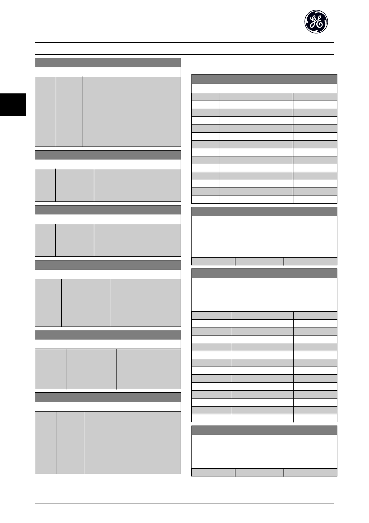
Parameter Description AF-600 FP Programming Guide
3
E-64 Pulse Filter Time Constant #29
Range: Function:
100
ms
*
[1 - 1000
ms]
Enter the pulse filter time constant. The
pulse filter dampens oscillations of the
feedback signal, which is an advantage if
there is a lot of noise in the system. A high
time constant value results in better
dampening but also increases the time
delay through the filter.
This parameter cannot be adjusted while
the motor is running.
E-65 Term. 33 Low Frequency
Range: Function:
100 Hz* [0 - 110000
Hz]
Enter the low frequency
corresponding to the low motor shaft
speed (i.e. low reference value) in
E-67 Term. 33 Low Ref./Feedb. Value.
E-66 Term. 33 High Frequency
Range: Function:
100 Hz* [0 - 110000
Hz]
Enter the high frequency
corresponding to the high motor shaft
speed (i.e. high reference value) in
E-68 Term. 33 High Ref./Feedb. Value.
E-67 Term. 33 Low Ref./Feedb. Value
Range: Function:
0.000 N/A* [-999999.999 -
999999.999 N/A]
Enter the low reference value
[RPM] for the motor shaft
speed. This is also the low
feedback value, see also
E-62 Term. 29 Low Ref./Feedb.
Value.
E-68 Term. 33 High Ref./Feedb. Value
Range: Function:
100.000 N/A* [-999999.999 -
999999.999 N/A]
Enter the high reference
value [RPM] for the motor
shaft speed. See also
E-63 Term. 29 High Ref./
Feedb. Value.
E-69 Pulse Filter Time Constant #33
Range: Function:
100 ms* [1 - 1000
ms]
Enter the pulse filter time constant. The
low-pass filter reduces the influence on
and dampens oscillations on the feedback
signal from the control.
This is an advantage, e.g. if there is a great
amount on noise in the system. This
parameter cannot be adjusted while the
motor is running.
3.3.5 E-7# Pulse Output
E-70 Terminal 27 Pulse Output Variable
Option: Function:
[0]
*
[45] Bus ctrl.
[48] Bus ctrl., timeout
[100] Output frequency
[101] Reference
[102] Feedback
[103] Motor Current
[104] Torque rel to limit
[105] Torq relate to rated
[106] Power
[107] Speed
[113] Ext. Closed Loop 1
[114] Ext. Closed Loop 2
[115] Ext. Closed Loop 3
E-71 Pulse Output Max Freq #27
Set the maximum frequency for terminal 27, corresponding to
the output variable selected in E-70 Terminal 27 Pulse Output
Variable.
This parameter cannot be adjusted while the motor is running.
Range: Function:
5000 Hz
E-72 Terminal 29 Pulse Output Variable
Select the variable for viewing on the terminal 29 display.
This parameter cannot be adjusted while the motor is running.
Same options and functions as par. group E-75.
Option: Function:
[0]
*
[45] Bus ctrl.
[48] Bus ctrl., timeout
[100] Output frequency
[101] Reference
[102] Feedback
[103] Motor Current
[104] Torque rel to limit
[105] Torq relate to rated
[106] Power
[107] Speed
[113] Ext. Closed Loop 1
[114] Ext. Closed Loop 2
[115] Ext. Closed Loop 3
E-74 Pulse Output Max Freq #29
Set the maximum frequency for terminal 29 corresponding to the
output variable set in E-72 Terminal 29 Pulse Output Variable.
This parameter cannot be adjusted while the motor is running.
Range: Function:
5000 Hz
No operation
*
*
[0 - 32000 Hz]
No operation
[0 - 32000 Hz]
46
Page 48

Parameter Description AF-600 FP Programming Guide
3
E-78 Pulse Output Max Freq #X30/6
Select the maximum frequency on terminal X30/6 referring to
the output variable in E-75 Terminal X30/6 Pulse Output Variable.
This parameter cannot be adjusted while the motor is running.
This parameter is active when the General Purpose I/O Option
Module (OPCGPIO) is mounted in the drive.
Range: Function:
5000. Hz
*
[0 - 32000 Hz]
3.3.6 E-9# Bus Controlled
This parameter group selects digital and relay outputs via
a fieldbus setting.
E-90 Digital & Relay Bus Control
Range: Function:
0 N/
A
*
[0 2147483647 N/
A]
This parameter holds the state of the
digital outputs and relays that is
controlled by bus.
A logical '1' indicates that the output is
high or active.
A logical '0' indicates that the output is
low or inactive.
Bit 0 CC Digital Output Terminal 27
Bit 1 CC Digital Output Terminal 29
Bit 2 GPIO Digital Output Terminal X
30/6
Bit 3 GPIO Digital Output Terminal X
30/7
Bit 4 CC Relay 1 output terminal
Bit 5 CC Relay 2 output terminal
Bit 6 Option B Relay 1 output
terminal
Bit 7 Option B Relay 2 output
terminal
Bit 8 Option B Relay 3 output
terminal
Bit
9-31
Reserved for future terminals
E-95 Pulse Out #29 Bus Control
Range: Function:
0.00 %* [0.00 - 100.00%]Contains the frequency to apply to
the digital output terminal 29, when
it is configured as [Bus Controlled].
E-96 Pulse Out #29 Timeout Preset
Range: Function:
0.00 %* [0.00 - 100.00%]Contains the frequency to apply to
the digital output terminal 29, when
it is configured as [Bus Controlled
Timeout] and timeout is detected
E-97 Pulse Out #X30/6 Bus Control
Range: Function:
0.00 %* [0.00 - 100.00 %] Contains the frequency to apply to
the digital output terminal X30/6,
when it is configured as [Bus
Controlled.
E-98 Pulse Out #X30/6 Timeout Preset
Range: Function:
0.00 %* [0.00 - 100.00%]Contains the frequency to apply to
the digital output terminal X30/6,
when it is configured as [Bus
Controlled Timeout] and time-out is
detected.
3
E-93 Pulse Out #27 Bus Control
Range: Function:
0.00 %* [0.00 - 100.00%]Contains the frequency to apply to
the digital output terminal 27, when
it is configured as [Bus Controlled].
E-94 Pulse Out #27 Timeout Preset
Range: Function:
0.00 %* [0.00 - 100.00%]Contains the frequency to apply to
the digital output terminal 27, when
it is configured as [Bus Controlled
Timeout] and timeout is detected.
47
Page 49

Parameter Description AF-600 FP Programming Guide
3
3.4 C-## Frequency Control Functions
3.4.1 C-0# Frequency Control Functions
C-01 Jump Frequency From [Hz]
Array [4]
Range: Function:
0 Hz
*
Application
dependent
C-02 Jump Speed From [RPM]
Array [4]
Range: Function:
0 RPM* [0 - par. F-17
RPM]
*
[0.0 - par. F-15
Hz]
[Application
dependant]
Some systems call for avoiding certain
output speeds due to resonance
problems in the system. Enter the
lower limits of the speeds to be
avoided.
Some systems call for
avoiding certain output
speeds due to resonance
problems in the system.
Enter the lower limits of
the speeds to be
avoided.
C-05 Multi-step Frequency 1 - 8
Array [8]
Range: Function:
digital inputs in parameter group E-0#
Digital Inputs.
C-03 Jump Speed To [RPM]
Array [4]
Range: Function:
0 RPM* [0 - par. F-17
RPM]
Some systems call for avoiding certain
output speeds due to resonance
problems in the system. Enter the
upper limits of the speeds to be
avoided.
C-04 Jump Frequency To [Hz]
Array [4]
Range: Function:
0 Hz* [0.0 - par. F-15
Hz]
Some systems call for avoiding certain
output speeds due to resonance
problems in the system. Enter the upper
limits of the speeds to be avoided.
C-05 Multi-step Frequency 1 - 8
Array [8]
Range: Function:
0.00 %* [-100.00 -
100.00 %]
Enter up to eight different preset
references (0-7) in this parameter, using
array programming. The preset reference
is stated as a percentage of the value
Ref
(F-53 Maximum Reference, for
MAX
closed loop see CL-14 Maximum
Reference/Feedb.). When using preset
references, select Preset ref. bit 0 / 1 / 2
[16], [17] or [18] for the corresponding
3.4.2 C-2# Jog Setup
C-20 Jog Speed [Hz]
Range: Function:
10.0 Hz* [0.0 - par.
F-15 Hz]
C-21 Jog Speed [RPM]
Range: Function:
300.
RPM
*
[0 - par.
F-17 RPM]
The jog speed is a fixed output speed
at which the frequency converter is
running when the jog function is
activated.
See also C-22 Jog Accel/Decel Time.
Enter a value for the jog speed n
which is a fixed output speed. The
frequency converter runs at this speed
when the jog function is activated. The
maximum limit is defined in F-17 Motor
Speed High Limit [RPM].
See also C-22 Jog Accel/Decel Time.
JOG
,
48
Page 50

Parameter Description AF-600 FP Programming Guide
3
C-22 Jog Accel/Decel Time
Range: Function:
20.00
[1.00
s
-
*
3600.00
s]
Enter the jog ramp time, i.e. the acceleration/
deceleration time between 0 RPM and the rated
motor speed (n
that the resultant output current required for the
given jog ramp time does not exceed the current
limit in F-43 Current Limit. The jog ramp time starts
upon activation of a jog signal via the keypad, a
selected digital input, or the serial communication
port.
par. C
− 22 =
) (set in P-06 Base Speed). Ensure
M,N
tjog
×
nnorm par. P
jog speed par. C
3.4.3 C-3# Frequency Setting 2 and 3
C-30 Frequency Command 2
Option: Function:
Select the reference input to be
used for the second reference
signal. F-01 Frequency Setting 1,
C-30 Frequency Command 2 and
C-34 Frequency Command 3 define
up to three different reference
signals. The sum of these reference
signals defines the actual reference.
This parameter cannot be adjusted
while the motor is running.
[0] No function
[1] Analog input 53
[2] Analog input 54
[7] Pulse input 29
[8] Pulse input 33
*
Digital Potentiometer
[20]
[21] Analog input X30/11 (OPCGPIO)
[22] Analog input X30/12 (OPCGPIO)
[23] Analog Input X42/1 (OPCAIO)
[24] Analog Input X42/3 (OPCAIO)
[25] Analog Input X42/5 (OPCAIO)
− 06
− 21
C-30 Frequency Command 2
Option: Function:
[30] Ext. Closed Loop 1
[31] Ext. Closed Loop 2
[32] Ext. Closed Loop 3
C-34 Frequency Command 3
Option: Function:
Select the reference input to be used
for the third reference signal.
F-01 Frequency Setting 1,
s
*
No function
[0]
[1] Analog input 53
[2] Analog input 54
[7] Pulse input 29
[8] Pulse input 33
[20] Digital Potentiometer
[21] Analog input X30/11 (OPCGPIO)
[22] Analog input X30/12 (OPCGPIO)
[23] Analog Input X42/1 (OPCAIO)
[24] Analog Input X42/3 (OPCAIO)
[25] Analog Input X42/5 (OPCAIO)
[30] Ext. Closed Loop 1
[31] Ext. Closed Loop 2
[32] Ext. Closed Loop 3
C-30 Frequency Command 2 and
C-34 Frequency Command 3 define
up to three different reference
signals. The sum of these reference
signals defines the actual reference.
This parameter cannot be adjusted
while the motor is running.
3.4.4 C-4# Semi-Auto Jump Freq Set-up
C-40 Semi-Auto Jump Freq Set-up
Option: Function:
[0] *Off No function
[1] Enabled Starts the Semi-Automatic Bypass set-up and
continue with the procedure described above.
3
49
Page 51

Parameter Description AF-600 FP Programming Guide
3
3.5 P-## Motor Data
3.5.1 P-0# Motor Data
P-02 Motor Power [HP]
Range: Function:
4.00
hp
*
[0.09 -
3000.00 hp]
Enter the nominal motor power in HP
according to the motor nameplate data.
The default value corresponds to the
nominal rated output of the unit.
This ameter cannot be adjusted while the
motor is running.
Depending on the choices made in
K-03 Regional Settings, either P-07 Motor
Power [kW] or P-02 Motor Power [HP] is
made invisible.
P-03 Motor Current
Range: Function:
7.20 A* [0.10 - 10000.00A]Enter the nominal motor current
value from the motor nameplate data.
This data is used for calculating motor
torque, motor thermal protection etc.
NOTE
This parameter cannot be adjusted while the motor is
running.
P-04 Auto Tune
Option: Function:
The Auto Tune function optimizes dynamic
motor performance by automatically
optimizing the advanced motor P-30 Stator
Resistance (Rs) to P-35 Main Reactance (Xh))
while the motor is stationary.
*
Off No function
[0]
[1] Full Auto
Tune
[2] Reduced
Auto Tune
performs Auto Tune of the stator resistance
, the rotor resistance Rr, the stator leakage
R
S
reactance X
and the main reactance Xh.
Performs a reduced Auto Tune of the stator
resistance R
option if an LC filter is used between the
frequency converter and the motor.
, the rotor leakage reactance X
1
in the system only. Select this
s
NOTE
For the best results of the frequency converter,
•
run Auto Tune on a cold motor
Auto Tune cannot be performed while the motor
•
is running
NOTE
Avoid generating external torque during Auto Tune.
NOTE
If one of the settings in parameter group P-## Motor Data
is changed, P-30 Stator Resistance (Rs) to P-39 Motor Poles,
the advanced motor parameters, will return to default
setting.
This parameter cannot be adjusted while the motor is
running.
NOTE
Full Auto Tune should be run without filter only while
reduced Auto Tune should be run with filter.
P-06 Base Speed
Range: Function:
1420.
RPM
*
[100 - 60000
RPM]
Enter the nominal motor speed
value from the motor nameplate
data. This data is used for calculating
automatic motor compensations.
NOTE
This parameter cannot be adjusted while the motor is
running.
P-07 Motor Power [kW]
Range: Function:
4.00
kW
2
*
[0.09 -
3000.00 kW]
Enter the nominal motor power in kW
according to the motor nameplate data.
The default value corresponds to the
nominal rated output of the unit.
This ameter cannot be adjusted while the
motor is running. Depending on the
choices made in K-03 Regional Settings,
either P-07 Motor Power [kW] or P-02 Motor
Power [HP] is made invisible.
Activate the Auto Tune function by pressing [Hand ] after
selecting [1] or [2]. After a normal sequence, the display
will read: “Press [OK] to finish Auto Tune”. After pressing
the [OK] key the frequency converter is ready for
operation.
50
Page 52

Parameter Description AF-600 FP Programming Guide
3
P-08 Motor Rotation Check
Option: Function:
Following installation and connection of the
motor, this function allows the correct motor
rotation direction to be verified. Enabling this
function overrides any bus commands or digital
inputs, except External Interlock.
*
Off Motor Rotation Check is not active.
[0]
[1] Enabled Motor Rotation Check is enabled. Once enabled,
Display shows:
“Note! Motor may run in wrong direction”.
Pressing [OK], [Back] or [Cancel] will dismiss the message
and display a new message: “Press [Hand] to start the
motor. Press [Cancel] to abort”. Pressing [Hand] starts the
motor at 5 Hz in forward direction and the display shows:
“Motor is running. Check if motor rotation direction is
correct. Press [Off] to stop the motor”. Pressing [Off] stops
the motor and resets P-08 Motor Rotation Check. If motor
rotation direction is incorrect, two motor phase cables
should be interchanged. IMPORTANT:
WARNING
Mains power must be removed before disconnecting
motor phase cables.
P-09 Slip Compensation
Range: Function:
0 %* [-500 - 500%]Enter the % value for slip compensation, to
compensate for tolerances in the value of
n
. Slip compensation is calculated
M,N
automatically, i.e. on the basis of the rated
motor speed n
P-10 Slip Compensation Time Constant
Range: Function:
0.10 s* [0.05 - 5.00s]Enter the slip compensation reaction
speed. A high value results in slow
reaction, and a low value results in quick
reaction. If low-frequency resonance
problems arise, use a longer time setting.
M,N
.
P-35 Main Reactance (Xh)
Range: Function:
100.0000
Ohm
*
[1.0000 -
10000.0000
Ohm]
Set the main reactance of the motor
using one of these methods:
1. Run an Auto Tune on a cold
motor. The frequency
converter will measure the
value from the motor.
2. Enter the X
Obtain the value from the
motor supplier.
3. Use the X
The frequency converter
establishes the setting on
the basis of the motor name
plate data.
value manually.
h
default setting.
h
NOTE
This parameter cannot be adjusted while running.
P-36 Iron Loss Resistance (Rfe)
Range: Function:
10000.000
Ohm
*
[0 -
10000.000
Ohm]
Enter the equivalent iron loss
resistance (R
compensate for iron losses in the
motor.
The R
performing an Auto Tune.
The R
important in torque control
applications. If R
leave P-36 Iron Loss Resistance (Rfe)
on default setting.
) value to
Fe
value cannot be found by
Fe
value is especially
Fe
is unknown,
Fe
NOTE
This parameter cannot be adjusted while the motor is
running.
3
3.5.2 P-3# Adv. Motor Data
P-30 Stator Resistance (Rs)
Range: Function:
1.4000
Ohm
*
[0.0140 -
140.0000 Ohm]
Set the stator resistance value. Enter
the value from a motor data sheet
or perform an Auto Tune on a cold
motor. This ameter cannot be
adjusted while the motor is running.
51
Page 53

Parameter Description AF-600 FP Programming Guide
3
3.6 H-## High Perf Parameters
3.6.1 H-0# High Perf Operations
H-03 Restore Factory Settings
Option: Function:
Use this parameter to specify normal
operation, to perform tests or to restore all
parameters except ID-03 Power Up's,
ID-04 Over Temp's and ID-05 Over Volt's. This
function is active only when the power is
cycled (power off-power on) to the frequency
converter.
*
Normal
[0]
operation
[2] Restore
Factory
Settings
H-04 Auto-Reset (Times)
Option: Function:
*
Manual reset Select Manual reset [0], to perform a
[0]
[1] Automatic reset x 1 Select Automatic reset x 1…x20 [1]-
[2] Automatic reset x 2
[3] Automatic reset x 3
[4] Automatic reset x 4
[5] Automatic reset x 5
[6] Automatic reset x 6
[7] Automatic reset x 7
[8] Automatic reset x 8
[9] Automatic reset x 9
[10] Automatic reset x 10
[11] Automatic reset x 15
[12] Automatic reset x 20
[13] Infinite auto reset Select Infinite Automatic Reset [13] for
Select Normal operation [0] for normal
operation of the frequency converter with the
motor in the selected application.
Select Restore Factory Settings [2] to reset all
parameter values to default settings, except
for ID-03 Power Up's, ID-04 Over Temp's and
ID-05 Over Volt's. The frequency converter will
reset during the next power-up.
H-03 Restore Factory Settings will also revert to
the default setting Normal operation [0].
Select the reset function after
tripping. Once reset, the frequency
converter can be restarted.
reset via [RESET] or via the digital
inputs.
[12] to perform between one and
twenty automatic resets after
tripping.
continuous resetting after tripping.
NOTE
The motor may start without warning. If the specified
number of AUTOMATIC RESETs is reached within 10
minutes, the frequency converter enters Manual reset [0]
mode. After the Manual reset is performed, the setting of
H-04 Auto-Reset (Times) reverts to the original selection. If
the number of automatic resets is not reached within 10
minutes, or when a Manual reset is performed, the internal
AUTOMATIC RESET counter returns to zero.
H-05 Auto-Reset (Reset Interval)
Range: Function:
10 s* [0 - 600 s] Enter the time interval from trip to start of
the automatic reset function. This parameter
is active when H-04 Auto-Reset (Times) is set
to Automatic reset [1] - [13].
H-06 Fan Operation
Option: Function:
Select the minimum speed of the main fan.
*
Auto Select Auto [0] to run the fan only when the
[0]
internal temperature of the frequency converter
is in the range +35
The fan will run at low speed at +35
full speed at approximately +55
[1] On 50%
[2] On 75%
[3] On 100%
°
C to approximately +55°C.
°
C and at
°
C.
H-08 Reverse Lock
Option: Function:
Selects the motor speed direction required.
Use this parameter to prevent unwanted
reversing.
[0] Clockwise Only operation in clockwise direction will
be allowed.
*
Both directions Operation in both clockwise and anti-
[2]
clockwise direction will be allowed.
NOTE
The setting in H-08 Reverse Lock has impact on the Flying
Start in H-09 Start Mode.
H-09 Start Mode
Option: Function:
This function makes it possible to catch a motor
which is spinning freely due to a mains drop-out.
When H-09 Start Mode is enabled, F-24 Holding
Time has no function.
Search direction for flying start is linked to the
setting in H-08 Reverse Lock.
52
Page 54

Parameter Description AF-600 FP Programming Guide
3
H-09 Start Mode
Option: Function:
Clockwise [0]: Flying start search in clockwise
direction. If not successful, a DC brake is carried
out.
Both Directions [2]: The flying start will first make
a search in the direction determined by the last
reference (direction). If not finding the speed it
will make a search in the other direction. If not
successful, a DC brake will be activated in the
time set in B-02 DC Braking Time. Start will then
take place from 0 Hz.
Disabled Select Disable [0] if this function is not required
[0]
*
[1] Enabled Select Enable [1] to enable the frequency
converter to “catch” and control a spinning
motor.
3.6.2 H-3##
H-37 Trip Speed Low [Hz]
Range: Function:
0.0 Hz* [0.0 - par.
F-17 Hz]
If the Trip Speed is set to 0, the function is
not active.
If the speed at any time after the start (or
during a stop) falls below the value in the
ameter, the drive will trip with an alarm
[A49] Speed Limit. Function at stop.
NOTE
This parameter is only available if K-02 Motor Speed Unit is
set to [Hz].
3.6.3 H-4# Advanced Settings
H-40 Configuration Mode
Option: Function:
[0] *Open
Loop
[3] Closed
Loop
Motor speed is determined by applying a speed
reference or by setting desired speed when in
Hand Mode.
Open Loop is also used if the frequency
converter is part of a closed loop control system
based on an external PID controller providing a
speed reference signal as output.
Motor Speed will be determined by a reference
from the built-in PID controller varying the
motor speed as part of a closed loop control
process (e.g. constant pressure or flow). The PID
controller must be configured in parameter
group CL-## or via the Function Setups accessed
by pressing the [Quick Menus] button.
NOTE
This parameter cannot be changed when motor is running.
NOTE
When set for Closed Loop, the commands Reversing and
Start Reversing will not reverse the direction of the motor.
H-43 Torque Characteristics
Option: Function:
[0] Compressor
torque
[1] Variable
torque
[2] Energy
Savings CT
Auto Energy
[3]
Optim. VT
*
Compressor [0]: For speed control of screw
and scroll compressors. Provides a voltage
which is optimized for a constant torque load
characteristic of the motor in the entire range
down to 10 Hz.
Variable Torque [1]: For speed control of
centrifugal pumps and fans. Also to be used
when controlling more than one motor from
the same frequency converter (e.g. multiple
condenser fans or cooling tower fans).
Provides a voltage which is optimized for a
squared torque load characteristic of the
motor.
Auto Energy Optimization Compressor [2]: For
optimum energy efficient speed control of
screw and scroll compressors. Provides a
voltage which is optimized for a constant
torque load characteristic of the motor in the
entire range down to 15Hz but in addition
the Energy Saving feature will adapt the
voltage exactly to the current load situation,
thereby reducing energy consumption and
audible noise from the motor. To obtain
optimal performance, the motor power factor
cos phi must be set correctly. This value is set
in SP-43 Motor Cosphi. The parameter has a
default value which is automatically adjusted
when the motor data is programmed. These
settings will typically ensure optimum motor
voltage but if the motor power factor cos phi
requires tuning, an auto tune function can be
carried out using P-04 Auto Tune. It is very
rarely necessary to adjust the motor power
factor parameter manually.
Energy Saving VT [3]: For optimum energy
efficient speed control of centrifugal pumps
and fans. Provides a voltage which is
optimized for a squared torque load characteristic of the motor but in addition the
Energy Saving feature will adapt the voltage
exactly to the current load situation, thereby
reducing energy consumption and audible
noise from the motor. To obtain optimal
performance, the motor power factor cos phi
must be set correctly. This value is set in
3
53
Page 55

Parameter Description AF-600 FP Programming Guide
3
H-43 Torque Characteristics
Option: Function:
SP-43 Motor Cosphi. The parameter has a
default value and is automatically adjusted
when the motor data is programmed. These
settings will typically ensure optimum motor
voltage but if the motor power factor cos phi
requires tuning, an auto tune function can be
carried out using P-04 Auto Tune. It is very
rarely necessary to adjust the motor power
factor parameter manually.
H-48 Clockwise Direction
This parameter defines the term “Clockwise” corresponding to
the keypad direction arrow. Used for easy change of direction of
shaft rotation without swapping motor wires. (Valid from SW
version 5.84)
Option: Function:
[0]
*
[1] Inverse Motor shaft will turn in counter
Normal Motor shaft will turn in clockwise
direction when the drive is
connected U -> U; V -> V, and W
-> W to motor.
clockwise direction when the
drive is connected U -> U; V -> V,
and W -> W to motor.
H-64 Resonance Dampening
Range: Function:
100 %* [0 - 500%]Enter the resonance dampening value. Set
H-64 Resonance Dampening and
H-65 Resonance Dampening Time Constant to
help eliminate high-frequency resonance
problems. To reduce resonance oscillation,
increase the value of H-64 Resonance
Dampening.
H-65 Resonance Dampening Time Constant
Range: Function:
5 ms* [5 - 50 ms] Set H-64 Resonance Dampening and
H-65 Resonance Dampening Time Constant to
help eliminate high-frequency resonance
problems. Enter the time constant that
provides the best dampening.
3.6.5 H-7# Adjustable Warnings
Warnings are shown on display, programmed output or
serial bus.
This parameter cannot be changed while the motor is
running.
3.6.4 H-6# Load Depend. Setting
H-61 High Speed Load Compensation
Range: Function:
100 %* [0 - 300%]Enter the % value to compensate voltage in
relation to load when the motor is running at
high speed and obtain the optimum U/f
characteristic. The motor size determines the
frequency range within which this ameter is
active.
Motor size Change-over
0.25 kW - 7.5 kW > 10 Hz
11 kW - 45 kW < 5 Hz
55 kW - 550 kW < 3-4 Hz
H-70 Warning Current Low
Range: Function:
0.00 A* [0.00 par. H-71
A]
Enter the I
current falls below this limit (I
display reads CURRENT LOW. The signal
outputs can be programmed to produce a
status signal on terminal 27 or 29 and on
relay output 01 or 02. Refer to the drawing
in this section.
value. When the motor
LOW
LOW
), the
54
Page 56

Parameter Description AF-600 FP Programming Guide
3
H-71 Warning Current High
Range: Function:
par.
DR-37 A
[par. H-70
- par. DR-37
*
A]
Enter the I
current exceeds this limit (I
display reads CURRENT HIGH. The signal
outputs can be programmed to produce
a status signal on terminal 27 or 29 and
on relay output 01 or 02. Refer to the
drawing in this section.
value. When the motor
HIGH
HIGH
), the
H-72 Warning Speed Low
Range: Function:
0 RPM* [0 - par.
H-73
RPM]
Enter the n
falls below this limit (n
SPEED LOW. The signal outputs can be
programmed to produce a status signal on
terminal 27 or 29 and on relay output 01 or
02. Programme the lower signal limit of the
motor speed, n
working range of the frequency converter.
Refer to the drawing in this section.
value. When the motor speed
LOW
) the display reads
LOW
, within the normal
LOW
H-73 Warning Speed High
Range: Function:
par. F-17 RPM* [par. H-72 - par. F-17 RPM]
NOTE
Any changes in F-17 Motor Speed High Limit [RPM] will reset
the value in H-73 Warning Speed High to the same value as
set in F-17 Motor Speed High Limit [RPM].
If a different value is needed in H-73 Warning Speed High, it
must be set after programming of F-17 Motor Speed High
Limit [RPM]
H-74 Warning Reference Low
Range: Function:
-999999.999
N/A
*
H-75 Warning Reference High
Range: Function:
999999.999
N/A
*
[-999999.999 par. H-75 N/A]
[par. H-74 -
999999.999 N/
A]
Enter the lower reference limit.
When the actual reference falls
below this limit, the display
indicates Ref Low. The signal
outputs can be programmed
to produce a status signal on
terminal 27 or 29 and on relay
output 01 or 02.
Enter the upper reference limit.
When the actual reference
exceeds this limit, the display
reads Ref High. The signal
outputs can be programmed to
produce a status signal on
terminal 27 or 29 and on relay
output 01 or 02.
H-76 Warning Feedback Low
Range: Function:
-999999.999
ProcessCtrlUnit
[-999999.999 par. H-77
*
ProcessCtrlUnit]
Enter the lower feedback
limit. When the feedback
falls below this limit, the
display reads Feedb Low.
The signal outputs can be
programmed to produce a
status signal on terminal
27 or 29 and on relay
output 01 or 02.
H-77 Warning Feedback High
Range: Function:
999999.999
ProcessCtrlUnit
[par. H-76 -
999999.999
*
ProcessCtrlUnit]
Enter the upper
feedback limit. When
the feedback exceeds
this limit, the display
reads Feedb High.
H-78 Missing Motor Phase Function
Option: Function:
Displays an alarm in the event of a missing
motor phase.
[0] Disabled No alarm is displayed if a missing motor
phase occurs.
*
Trip 1000 ms
[2]
NOTE
This parameter cannot be adjusted while the motor is
running.
3.6.6 H-8# Stop Adjustments
H-80 Function at Stop
Option: Function:
Select the frequency converter function
after a stop command or after the speed is
deceled to the settings in H-81 Min Speed
for Function at Stop [RPM].
*
Coast Leaves motor in free mode.
[0]
[1] DC Hold/
Motor
Preheat
H-81 Min Speed for Function at Stop [RPM]
Range: Function:
3. RPM* [0 - 600 RPM] Set the speed at which to activate
Energizes motor with a DC holding current
(see B-00 DC Hold Current).
H-80 Function at Stop.
3
55
Page 57

3
Parameter Description AF-600 FP Programming Guide
H-82 Min Speed for Function at Stop [Hz]
Range: Function:
0.1 Hz* [0.0 - 20.0 Hz] Set the output frequency at which to
activate H-80 Function at Stop.
56
Page 58

Parameter Description AF-600 FP Programming Guide
3
3.7 AN-## Analog In/Out
Parameter group for configuration of the analog input and
output.
3.7.1 AN-0# Analog I/O Mode
Parameter group for setting up the analog I/O configuration.
The frequency converter is equipped with 2 analog inputs:
Terminal 53 and 54. The analog inputs can freely be
allocated to either voltage (0 - 10 V) or current input (0/4 20 mA)
NOTE
Thermistors may be connected to either an analog or a
digital input.
AN-00 Live Zero Timeout Time
Range: Function:
10 s* [1 -
Enter the Live Zero Time-out time period. Live
99 s]
Zero Time-out Time is active for analog inputs, i.e.
terminal 53 or terminal 54, used as reference or
feedback sources. If the reference signal value
associated with the selected current input falls
below 50% of the value set in AN-10 Terminal 53
Low Voltage, AN-12 Terminal 53 Low Current,
AN-20 Terminal 54 Low Voltage or AN-22 Terminal
54 Low Current for a time period longer than the
time set in AN-00 Live Zero Timeout Time, the
function selected in AN-01 Live Zero Timeout
Function will be activated.
AN-01 Live Zero Timeout Function
Option: Function:
[4] overruled to max. speed
•
[5] overruled to stop with subsequent
•
trip
*
Off
[0]
[1] Freeze
output
[2] Stop
[3] Jogging
[4] Max.
speed
[5] Stop and
trip
AN-02 Fire Mode Live Zero Timeout Function
Option: Function:
The function set in AN-01 Live Zero Timeout
Function will be activated if the input signal
on analogue inputs is below 50% of the
value defined in parameter group AN-1# to
AN-6# "Terminal xx Low Current” or
“Terminal xx Low Voltage" for a time period
defined in AN-00 Live Zero Timeout Time.
*
Off
[0]
[1] Freeze output
[2] Stop
[3] Jogging
[4] Max. speed
3.7.2 AN-1# Analog Input 1
3
AN-01 Live Zero Timeout Function
Option: Function:
Select the time-out function. The function set
in AN-01 Live Zero Timeout Function will be
activated if the input signal on terminal 53 or
54 is below 50% of the value in AN-10 Terminal
53 Low Voltage, AN-12 Terminal 53 Low Current,
AN-20 Terminal 54 Low Voltage or
AN-22 Terminal 54 Low Current for a time
period defined in AN-00 Live Zero Timeout Time.
If several time-outs occur simultaneously, the
frequency converter prioritises the time-out
functions as follows:
1. AN-01 Live Zero Timeout Function
2. O-04 Control Word Timeout Function
The output frequency of the frequency
converter can be:
[1] frozen at the present value
•
[2] overruled to stop
•
[3] overruled to jog speed
•
Parameters for configuring the scaling and limits for
analog input 1 (terminal 53).
57
Page 59

Parameter Description AF-600 FP Programming Guide
3
AN-10 Terminal 53 Low Voltage
Range: Function:
0.07 V* [0.00 - par.
AN-11 V]
Enter the low voltage value. This analog
input scaling value should correspond
to the low reference/feedback value set
in AN-14 Terminal 53 Low Ref./Feedb.
Value.
AN-11 Terminal 53 High Voltage
Range: Function:
10.00 V* [par. AN-10 -
10.00 V]
Enter the high voltage value. This
analog input scaling value should
correspond to the high reference/
feedback value set in AN-15 Terminal 53
High Ref./Feedb. Value.
AN-12 Terminal 53 Low Current
Range: Function:
4.00
mA
*
[0.00 par. AN-13
mA]
Enter the low current value. This reference
signal should correspond to the low
reference/feedback value, set in
AN-14 Terminal 53 Low Ref./Feedb. Value.
The value must be set at >2 mA in order
to activate the Live Zero Time-out
Function in AN-01 Live Zero Timeout
Function.
AN-16 Terminal 53 Filter Time Constant
Range: Function:
0.001 s* [0.001 -
10.000 s]
Enter the time constant. This is a firstorder digital low pass filter time constant
for suppressing electrical noise in terminal
53. A high time constant value improves
dampening but also increases the time
delay through the filter.
This parameter cannot be adjusted while
the motor is running.
AN-17 Terminal 53 Live Zero
Option: Function:
This parameter makes it possible to disable the
Live Zero monitoring. E.g. to be used if the
analog outputs are used as part of a de-central I/
O system (e.g. when not as part of any frequency
converter related control functions, but feeding a
Building Management system with data).
[0] Disabled
*
Enabled
[1]
3.7.3 AN-2# Analog Input 2
Parameters for configuring the scaling and limits for
analog input 2 (terminal 54).
AN-13 Terminal 53 High Current
Range: Function:
20.00 mA* [par. AN-12 -
20.00 mA]
Enter the high current value
corresponding to the high
reference/feedback set in
AN-15 Terminal 53 High Ref./Feedb.
Value.
AN-14 Terminal 53 Low Ref./Feedb. Value
Range: Function:
0.000 N/A* [-999999.999 -
999999.999 N/A]
Enter the analog input scaling
value that corresponds to the
low voltage/low current set in
AN-10 Terminal 53 Low Voltage
and AN-12 Terminal 53 Low
Current.
AN-15 Terminal 53 High Ref./Feedb. Value
Range: Function:
60.000 N/
A
*
[-999999.999 -
999999.999 N/A]
Enter the analog input scaling
value that corresponds to the
high voltage/high current value
set in AN-11 Terminal 53 High
Voltage and AN-13 Terminal 53
High Current.
AN-20 Terminal 54 Low Voltage
Range: Function:
0.07 V* [0.00 - par.
AN-21 V]
Enter the low voltage value. This analog
input scaling value should correspond
to the low reference/feedback value, set
in AN-24 Terminal 54 Low Ref./Feedb.
Value.
58
Page 60

Parameter Description AF-600 FP Programming Guide
3
AN-21 Terminal 54 High Voltage
Range: Function:
10.00 V* [par. AN-20 -
10.00 V]
Enter the high voltage value. This
analog input scaling value should
correspond to the high reference/
feedback value set in AN-25 Terminal 54
High Ref./Feedb. Value.
AN-22 Terminal 54 Low Current
Range: Function:
4.00
mA
*
[0.00 par. AN-23
mA]
Enter the low current value. This reference
signal should correspond to the low
reference/feedback value, set in
AN-24 Terminal 54 Low Ref./Feedb. Value.
The value must be set at >2 mA in order
to activate the Live Zero Time-out
Function in AN-01 Live Zero Timeout
Function.
AN-23 Terminal 54 High Current
Range: Function:
20.00 mA* [par. AN-22 -
20.00 mA]
Enter the high current value
corresponding to the high
reference/feedback value set in
AN-25 Terminal 54 High Ref./Feedb.
Value.
AN-24 Terminal 54 Low Ref./Feedb. Value
Range: Function:
0.000 N/
A
*
[-999999.999 -
999999.999 N/A]
Enter the analog input scaling
value that corresponds to the
low voltage/low current value
set in AN-20 Terminal 54 Low
Voltage and AN-22 Terminal 54
Low Current.
AN-25 Terminal 54 High Ref./Feedb. Value
Range: Function:
100.000 N/
A
*
[-999999.999 -
999999.999 N/A]
Enter the analog input scaling
value that corresponds to the
high voltage/high current
value set in AN-21 Terminal 54
High Voltage and
AN-23 Terminal 54 High Current.
AN-26 Terminal 54 Filter Time Constant
Range: Function:
0.001 s* [0.001 -
10.000 s]
Enter the time constant. This is a firstorder digital low pass filter time constant
for suppressing electrical noise in terminal
54. A high time constant value improves
dampening but also increases the time
delay through the filter.
This parameter cannot be adjusted while
the motor is running.
AN-27 Terminal 54 Live Zero
Option: Function:
This parameter makes it possible to disable the
Live Zero monitoring. E.g. to be used if the
analog outputs are used as part of a de-central I/
O system (e.g. when not as part of any frequency
converter related control functions, but feeding a
Building Management System with data).
[0] Disabled
*
Enabled
[1]
3.7.4 AN-3# Analog Input 3 OPCGPIO
General Purpose I/O
Parameter group for configuring the scale and limits for
analog input 3 (X30/11) placed on option module
OPCGPIO General Purpose I/O.
AN-30 Terminal X30/11 Low Voltage
Range: Function:
0.07 V* [0.00 - par.
AN-31 V]
AN-31 Terminal X30/11 High Voltage
Range: Function:
10.00 V* [par. AN-30 -
10.00 V]
AN-34 Term. X30/11 Low Ref./Feedb. Value
Range: Function:
0.000 N/A* [-999999.999 -
999999.999 N/A]
AN-35 Term. X30/11 High Ref./Feedb. Value
Range: Function:
100.000 N/A* [-999999.999 -
999999.999 N/A]
Sets the analog input scaling value to
correspond to the low reference/
feedback value (set in AN-34 Term.
X30/11 Low Ref./Feedb. Value).
Sets the analog input scaling value to
correspond to the high reference/
feedback value (set in AN-35 Term.
X30/11 High Ref./Feedb. Value).
Sets the analog input scaling
value to correspond to the low
voltage value (set in
AN-30 Terminal X30/11 Low
Voltage).
Sets the analog input scaling
value to correspond to the
high voltage value (set in
AN-31 Terminal X30/11 High
Voltage).
3
59
Page 61

Parameter Description AF-600 FP Programming Guide
3
AN-36 Term. X30/11 Filter Time Constant
Range: Function:
0.001 s* [0.001 -
10.000 s]
st
order digital low pass filter time
A 1
constant for suppressing electrical
noise on terminal X30/11.
AN-36 Term. X30/11 Filter Time Constant
cannot be changed while the motor is
running.
AN-37 Term. X30/11 Live Zero
Option: Function:
This parameter makes it possible to disable the
Live Zero monitoring. E.g. to be used if the
analog outputs are used as part of a decentral I/
O system (e.g. when not part of any frequency
converter related control functions, but feeding a
Building Management System with data).
*
Disabled
[0]
*
Enabled
[1]
3.7.5 AN-4# Analog Input 4 OPCGPIO
General Purpose I/O
Parameter group for configuring the scale and limits for
analog input 4 (X30/12) placed on option module
OPCGPIO General Purpose I/O.
AN-40 Terminal X30/12 Low Voltage
Range: Function:
0.07 V* [0.00 - par.
AN-41 V]
AN-41 Terminal X30/12 High Voltage
Range: Function:
10.00 V* [par. AN-40 -
10.00 V]
AN-44 Term. X30/12 Low Ref./Feedb. Value
Range: Function:
0.000 N/A* [-999999.999 -
999999.999 N/A]
Sets the analog input scaling value to
correspond to the low reference/
feedback value set in AN-44 Term.
X30/12 Low Ref./Feedb. Value.
Sets the analog input scaling value to
correspond to the high reference/
feedback value set in AN-45 Term.
X30/12 High Ref./Feedb. Value.
Sets the analog output scaling
value to correspond to the low
voltage value set in
AN-40 Terminal X30/12 Low
Voltage.
AN-45 Term. X30/12 High Ref./Feedb. Value
Range: Function:
100.000 N/A* [-999999.999 -
999999.999 N/A]
Sets the analog input scaling
value to correspond to the
high voltage value set in
AN-41 Terminal X30/12 High
Voltage.
AN-46 Term. X30/12 Filter Time Constant
Range: Function:
0.001 s* [0.001 -
10.000 s]
st
order digital low pass filter time
A 1
constant for suppressing electrical
noise on terminal X30/12.
AN-46 Term. X30/12 Filter Time Constant
cannot be changed while the motor is
running.
AN-47 Term. X30/12 Live Zero
Option: Function:
This parameter makes it possible to disable the
Live Zero monitoring. E.g. to be used if the
analog outputs are used as part of a decentral I/
O system (e.g. when not part of any frequency
converter related control functions, but feeding a
Building Management System with data)
*
Disabled
[0]
*
Enabled
[1]
3.7.6 AN-5# Analog Output 1
Parameters for configuring the scaling and limits for
analog output 1, i.e. Terminal 42. Analog outputs are
current outputs: 0/4 – 20 mA. Common terminal (terminal
39) is the same terminal and has the same electrical
potential for analog common and digital common
connection. Resolution on analog output is 12 bit.
AN-50 Terminal 42 Output
Option: Function:
Select the function of Terminal 42 as
an analog current output. A motor
current of 20 mA corresponds to I
[0] No operation
[100] Output frequency 0 - 100 Hz, (0-20 mA)
[101] Reference Minimum reference - Maximum
reference, (0-20 mA)
[102] Feedback -200% to +200% of CL-14 Maximum
Reference/Feedb., (0-20 mA)
[103] Motor Current 0 - Inverter Max. Current (DR-37 Drive
Max. Current), (0-20 mA)
[104] Torque rel to limit 0 - Torque limit (F-40 Torque Limiter
(Driving)), (0-20 mA)
max
.
60
Page 62

Parameter Description AF-600 FP Programming Guide
3
AN-50 Terminal 42 Output
Option: Function:
[105] Torq relate to
rated
[106] Power 0 - Motor rated power, (0-20 mA)
[107] Speed 0 - Speed High Limit (F-17 Motor
[113] Ext. Closed Loop 1 0 - 100%, (0-20 mA)
[114] Ext. Closed Loop 2 0 - 100%, (0-20 mA)
[115] Ext. Closed Loop 3 0 - 100%, (0-20 mA)
[130] Output freq.
4-20mA
[131] Reference 4-20mA Minimum Reference - Maximum
[132] Feedback 4-20mA -200% to +200% of CL-14 Maximum
[133] Motor cur. 4-20mA 0 - Inverter Max. Current (DR-37 Drive
[134] Torq.% lim 4-20mA0 - Torque limit (F-40 Torque Limiter
[135] Torq.% nom
4-20mA
[136] Power 4-20mA 0 - Motor rated power
*
Speed 4-20mA 0 - Speed High Limit (F-17 and F-15)
[137]
[139] Bus ctrl. 0 - 100%, (0-20 mA)
[140] Bus ctrl. 4-20 mA 0 - 100%
[141] Bus ctrl t.o. 0 - 100%, (0-20 mA)
[142] Bus ctrl t.o.
4-20mA
[143] Ext. CL 1 4-20mA 0 - 100%
[144] Ext. CL 2 4-20mA 0 - 100%
[145] Ext. CL 3 4-20mA 0 - 100%
0 - Motor rated torque, (0-20 mA)
Speed High Limit [RPM] and
F-15 Motor Speed High Limit [Hz]),
(0-20 mA)
0 - 100 Hz
Reference
Reference/Feedb.
Max. Current)
(Driving))
0 - Motor rated torque
0 - 100%
AN-51 Terminal 42 Output Min Scale
Range: Function:
0.00 %* [0.00 -
200.00 %]
Scale for the minimum output (0 or
4mA) of the analog signal at terminal 42.
Set the value to be the percentage of
the full range of the variable selected in
AN-50 Terminal 42 Output.
AN-52 Terminal 42 Output Max Scale
Range: Function:
100.00
%
20 mA/
i.e
[0.00 -
200.00
*
%]
desired maximum current
. 10mA:
Scale for the maximum output (20 mA) of the
analog signal at terminal 42.
Set the value to be the percentage of the full
range of the variable selected in
AN-50 Terminal 42 Output.
It is possible to get a value lower than 20 mA
at full scale by programming values >100%
by using a formula as follows:
20
mA
10
mA
× 100 %
× 100 % = 200 %
EXAMPLE 1:
Variable value= OUTPUT FREQUENCY, range = 0-100 Hz
Range needed for output = 0-50 Hz
Output signal 0 or 4 mA is needed at 0 Hz (0% of range) set AN-51 Terminal 42 Output Min Scale to 0%
Output signal 20 mA is needed at 50 Hz (50% of range) set AN-52 Terminal 42 Output Max Scale to 50%
3
NOTE
Values for setting the Minimum Reference is found in open
loop F-52 Minimum Reference and for closed loop
CL-13 Minimum Reference/Feedb. - values for maximum
reference for open loop is found in F-53 Maximum
Reference and for closed loop CL-14 Maximum Reference/
Feedb..
61
Page 63

Parameter Description AF-600 FP Programming Guide
3
EXAMPLE 2:
Variable= FEEDBACK, range= -200% to +200%
Range needed for output= 0-100%
Output signal 0 or 4 mA is needed at 0% (50% of range) set AN-51 Terminal 42 Output Min Scale to 50%
Output signal 20 mA is needed at 100% (75% of range) set AN-52 Terminal 42 Output Max Scale to 75%
EXAMPLE 3:
Variable value= REFERENCE, range= Min ref - Max ref
Range needed for output= Min ref (0%) - Max ref (100%),
0-10 mA
Output signal 0 or 4 mA is needed at Min ref - set
AN-51 Terminal 42 Output Min Scale to 0%
Output signal 10 mA is needed at Max ref (100% of range)
- set AN-52 Terminal 42 Output Max Scale to 200%
(20 mA / 10 mA x 100%=200%).
AN-53 Terminal 42 Output Bus Control
Range: Function:
0.00 %* [0.00 - 100.00 %] Holds the level of Output 42 if
controlled by bus.
AN-54 Terminal 42 Output Timeout Preset
Range: Function:
0.00 %* [0.00 -
100.00 %]
Holds the preset level of Output 42.
In case of a bus timeout and a timeout
function is selected in AN-50 Terminal 42
Output the output will preset to this
level.
3.7.7 AN-6# Analog Output 2 OPCGPIO
General Purpose I/O
AN-60 Terminal X30/8 Output
Same options and functions as AN-50 Terminal 42 Output.
AN-61 Terminal X30/8 Min. Scale
Range: Function:
0.00
[0.00 -
%
200.00 %]
*
Scales the minimum output of the selected
analog signal on terminal X30/8. Scale the
minimum value as a percentage of the
maximum signal value, i.e. 0mA (or 0hz) is
desired at 25% of the maximum output value
and 25% is programmed. The value can never
be higher than the corresponding setting in
AN-62 Terminal X30/8 Max. Scale if value is
below 100%.
This parameter is active when option module
OPCGPIO General Purpose I/O Option Module
is mounted in the drive.
AN-62 Terminal X30/8 Max. Scale
Range: Function:
100.00
[0.00
Scales the maximum output of the selected
%
-
*
analog signal on terminal X30/8. Scale the value
200.00
to the desired maximum value of the current
%]
signal output. Scale the output to give a lower
current than 20 mA at full scale or 20 mA at an
output below 100% of the maximum signal value.
If 20 mA is the desired output current at a value
between 0 - 100% of the ful-scale output,
program the percentage value in the parameter,
i.e. 50% = 20 mA. If a current between 4 and 20
mA is desired at maximum output (100%),
calculate the percentage value as follows:
20 mA/
i.e
desired maximum current
20
. 10 mA:
mA
× 100 % = 200 %
10
mA
× 100%
AN-63 Terminal X30/8 Output Bus Control
Range: Function:
0.00 %* [0.00 - 100.00 %] Contains the value to apply to the
output terminal, when it is
configured as [Bus Controlled].
AN-64 Terminal X30/8 Output Timeout Preset
Range: Function:
0.00 %* [0.00 - 100.00%]Contains the value to apply to the
output terminal, when it is configured
as [Bus Controlled Timeout] and timeout is detected.
Analog outputs are current outputs: 0/4 - 20mA. Common
terminal (terminal X30/8) is the same terminal and
electrical potential for analog common connection.
Resolution on analog output is 12 bit.
62
Page 64

Parameter Description AF-600 FP Programming Guide
3
3.8 SP-## Special Functions
Parameter group for configuring special frequency
converter functions.
3.8.1 SP-1#Line On/Off
Parameters for configuring mains failure monitoring and
handling.
SP-10 Line failure
Option: Function:
Select the function at which the frequency
converter must act, when the threshold set in
SP-11 Line Voltage at Input Fault has been
reached or a Mains Failure Inverse command is
activated via one of the digital inputs (par.
E-0#).
*
No
[0]
function
[1] Ctrl. Decel The frequency converter will perform a
[3] Coasting The inverter will turn off and the capacitor
[4] Kinetic
back-up
The energy left in the capacitor bank will be
used to "drive" the motor, but will be
discharged.
controlled decel. B-10 Brake Function must be
set to Off [0].
bank will back up the control card then
ensuring a faster restart when mains
reconnected (at short power zags).
The frequency converter will ride through by
controlling speed for generative operation of
the motor utilizing the moment of inertia of
the system as long as sufficient energy is
present.
NOTE
For best performance of controlled decel and kinetic backup H-43 Torque Characteristics should be set to Compressor
[0] or Variable Torque [1] (no Energy Saving should be
active).
Illustration 3.1 Controlled decel - short mains failure. Decelling
to stop followed by accelling to reference.
Illustration 3.2 Controlled decel, longer mains failure. Decelling
as long as the energy in the system allows for it, then the motor
is coasted.
Illustration 3.3 Kinetic Back-up, short mains failure. Ride through
as long as the energy in the system allows for it.
Illustration 3.4 Kinetic Back-up, longer mains failure. The motor is
coasted as soon as the energy in the system is too low.
SP-11 Line Voltage at Input Fault
Range: Function:
342. V* [180 - 600V]This parameter defines the threshold
voltage at which the selected function in
SP-10 Line failure should be activated. The
detection level is at a faktor sqrt(2) of the
value in SP-11 Line Voltage at Input Fault.
SP-12 Function at Line Imbalance
Option: Function:
Operation under severe main imbalance
conditions reduces the lifetime of the motor.
Conditions are considered severe if the motor is
operated continuously near nominal load (e.g. a
pump or fan running near full speed).
When a severe mains imbalance is detected:
*
Trip Select Trip [0] to trip the frequency converter.
[0]
[1] Warning Select Warning [1] to issue a warning.
[2] Disabled Select Disabled [2] for no action.
[3] Derate Select Derate [3] for derating the frequency
converter.
3
Parameters for configuring auto reset handling, special trip
handling and control card self test or restore.
63
Page 65

Parameter Description AF-600 FP Programming Guide
3
SP-25 Trip Delay at Torque Limit
Range: Function:
60 s* [0 - 60s]Enter the torque limit trip delay in seconds.
When the output torque reaches the torque
limits (F-40 Torque Limiter (Driving) and
F-41 Torque Limiter (Braking)), a warning is
triggered. When the torque limit warning has
been continuously present for the period
specified in this parameter, the frequency
converter trips. Disable the trip delay by setting
the parameter to 60 s = OFF. Thermal frequency
converter monitoring will still remain active.
SP-26 Trip Delay at Drive Fault
Range: Function:
0. s* [0 - 35 s] When the frequency converter detects an overvoltage in the set time trip will be effected
after the set time.
SP-29 Service Code
Range: Function:
0 N/A* [-2147483647 - 2147483647 N/A] Service use only.
3.8.2 SP-3# Current Limit Control
The frequency converter features an integral Current Limit
Controller which is activated when the motor current, and
thus the torque, is higher than the torque limits set in
F-40 Torque Limiter (Driving) and F-41 Torque Limiter
(Braking).
When the current limit is reached during motor operation
or regenerative operation, the frequency converter will try
to reduce torque below the preset torque limits as quickly
as possible without losing control of the motor.
While the current control is active, the frequency converter
can only be stopped by setting a digital input to Coast
inverse [2] or Coast and reset inv. [3]. Any signal on
terminals 18 to 33 will not be active until the frequency
converter is no longer near the current limit.
By using a digital input set to Coast inverse [2] or Coast
and reset inv. [3], the motor does not use the decel time,
since the frequency converter is coasted.
SP-30 Current Lim Ctrl, Proportional Gain
Range: Function:
100 %* [0 - 500 %] Enter the proportional gain value for the
current limit controller. Selection of a high
value makes the controller react faster. Too
high a setting leads to controller
instability.
SP-31 Current Lim Ctrl, Integration Time
Range: Function:
0.020 s* [0.002 - 2.000s]Controls the current limit control
integration time. Setting it to a lower
value makes it react faster. A setting
too low leads to control instability.
SP-32 Current Lim Ctrl, Filter Time
Range: Function:
26.0 ms* [1.0 - 100.0 ms] Sets a time constant for the current
limit controller low-pass filter.
3.8.3 SP-4#Energy Savings
Parameters for adjusting the energy optimisation level in
both Variable Torque (VT) and Energy Saving mode.
Energy Saving is only active if H-43 Torque Characteristics, is
set for either Energy Savings CT [2] or Auto Energy Optim.
VT [3].
SP-40 VT Level
Range: Function:
66 %* [40 - 90%]Enter the level of motor magnetisation at low
speed. Selection of a low value reduces
energy loss in the motor, but also reduces
load capability.
This parameter cannot be adjusted while the
motor is running.
SP-41 Energy Savings Min. Magnetization
Range: Function:
40. %* [40 - 75 %] Enter the minimum allowable magneti-
sation for Automatic Energy Savings.
Selection of a low value reduces energy
loss in the motor, but can also reduce
resistance to sudden load changes.
SP-42 Energy Savings Min. Frequency
Range: Function:
10 Hz* [5 - 40 Hz] Enter the minimum frequency at which the
Automatic Energy Savings is to be active.
SP-43 Motor Cosphi
Range: Function:
0.66 N/
A
[0.40 -
0.95 N/A]
*
The Cos(phi) setpoint is automatically set
for optimum Energy Saving performance
during Auto Tune. This parameter should
normally not be altered. However in some
situations it may be necessary to enter a
new value to fine-tune.
64
Page 66

Parameter Description AF-600 FP Programming Guide
3
3.8.4 SP-5# Environment
These parameters help the drive to operate under special
environmental conditions.
SP-50 RFI Filter
This parameter is only available for AF-650 GP. It is not relevant
to due to different design and shorter motor cables.
Option: Function:
[0] Off Select Off [0] if the drive is fed by an isolated mains
source (IT mains).
If a filter is used, select Off [0] during charging to
prevent a high leakage current making the RCD
switch.
In this mode, the internal RFI filter capacitors between
chassis and the mains RFI filter circuit are cut-out to
reduce the ground capacity currents.
*
On Select On [1] to ensure that the drive complies with
[1]
EMC standards.
SP-51 DC Link Compensation
Option: Function:
[0] Off Disables DC Link Compensation.
*
[1]
[0] Disabled
[1]
[2] Trip
On Enables DC Link Compensation.
SP-53 Fan Monitor
Option: Function:
Select which reaction the drive should take in
case a fan fault is detected.
*
Warning
3.8.5 SP-6# Automatic Derate
This group contains parameters for derating the frequency
converter in case of high temperature.
SP-60 Function at Over Temperature
Option: Function:
If either heatsink or control card temperature
exceeds a factory-programmed temperature limit, a
warning will be activated. If the temperature
increases further, select whether the frequency
converter should trip (trip locked) or derate the
output current.
*
Trip The frequency converter will trip (trip locked) and
[0]
generate an alarm. Power must be cycled to reset
the alarm, but will not allow restart of the motor
until the heat sink temperature has dropped below
the alarm limit.
[1] Derate If the critical temperature is exceeded the output
current will be reduced until the allowable
temperature has been reached.
130BB908.10
SP-61 Function at Drive Overload
Option: Function:
Is used in case of steady overload beyond the
thermal limits (110% for 60 sec.).
*
Trip Choose Trip [0] to make the frequency converter
[0]
trip and provide an alarm.
[1] Derate Derate [1] to reduce pump speed in order to
decrease the load on the power section and
allowing this to cool down.
SP-62 Drive Overload Derate Current
Range: Function:
95 %* [50 - 100%]Defines the desired current level (in % of
rated output current for the frequency
converter) when running with reduced
pump speed after load on the frequency
converter has exceeded the allowable limit
(110% for 60 sec.).
3
SP-55 Output Filter
Option: Function:
[0]
*
No Filter
[2] Sine Wave Filter Fixed
65
Page 67

Parameter Description AF-600 FP Programming Guide
3
3.9 O-## Options/Comms
3.9.1 O-0# General Settings
O-01 Control Site
Option: Function:
The setting in this parameter overrides
the settings in O-50 Coasting Select to
O-56 Preset Reference Select.
*
Digital and
[0]
ctrl.word
[1] Digital only Control by using digital inputs only.
[2] Controlword only Control by using control word only.
Control by using both digital input and
control word.
O-02 Control Word Source
Option: Function:
Select the source of the control word: one of
two serial interfaces or four installed options.
During initial power-up, the drive automatically
sets this parameter to Option A [3] if it detects a
valid network option installed in slot A. If the
option is removed, the drive detects a change
in the configuration, sets O-02 Control Word
Source back to default setting Drive Port, and the
drive then trips. If an option is installed after
initial power-up, the setting of O-02 Control
Word Source will not change but the drive will
trip and display: Alarm 67 Option Changed.
The drive port is the RS-485 port running the
protocol as set in par. O-30 ([0] Drive, [1] Drive
MC, [2] Modbus RTU, [3] Metasys N2, or [4] FLN
[0] None
[1] Drive
Port
[2] USB Port
*
Option A
[3]
[4] Option B
The drive port is the RS-485 port running the
protocol as set in parameter O-30; Drive, Drive
MC, Modbus RTU, Metasys N2, or FLN
NOTE
This parameter cannot be adjusted while the motor is
running.
O-03 Control Word Timeout Time
Range: Function:
In BACnet the control timeout is only
triggered if some specific objects are written.
The object list hold information on the
objects that triggers the control timeout:
Analog Outputs
Binary Outputs
AV0
AV1
AV2
AV4
BV1
BV2
BV3
BV4
BV5
Multistate Outputs
O-04 Control Word Timeout Function
Option: Function:
Select the time-out function. The
time-out function is activated when
the control word fails to be updated
within the time period specified in
O-03 Control Word Timeout Time.
Choice [20] only appears after setting
the Metasys N2 protocol.
*
Off
[0]
[1] Freeze output
[2] Stop
[3] Jogging
[4] Max. speed
[5] Stop and trip
[7] Select setup 1
[8] Select setup 2
[9] Select setup 3
[10] Select setup 4
[20] N2 Override Release
O-03 Control Word Timeout Time
Range: Function:
60.0
66
[1.0 -
s
18000.0 s]
*
Enter the maximum time expected to pass
between the reception of two consecutive
messages. If this time is exceeded, it indicates
that the serial communication has stopped.
The function selected in O-04 Control Word
Timeout Function Control Time-out Function
will then be carried out.
Page 68

Parameter Description AF-600 FP Programming Guide
3
O-05 End-of-Timeout Function
Option: Function:
Select the action after receiving a valid
control word following a time-out. This
parameter is active only when O-04 Control
Word Timeout Function is set to [Set-up 1-4].
[0] Hold set-up Retains the set-up selected in O-04 Control
Word Timeout Function and displays a
warning, until O-06 Reset Control Word
Timeout toggles. Then the drive resumes its
original set-up.
*
Resume set-upResumes the set-up active prior to the time-
[1]
out.
O-06 Reset Control Word Timeout
Option: Function:
This parameter is active only when the choice
Hold set-up [0] has been selected in O-05 End-ofTimeout Function .
*
Do not
[0]
reset
[1] Do reset Returns the drive to the original set-up following
Retains the set-up specified in O-04 Control Word
Timeout Function, [Select setup 1-4] following a
control time-out.
a control word time-out. When the value is set
to Do reset [1], the drive performs the reset and
then immediately reverts to the Do not reset [0]
setting.
O-07 Diagnosis Trigger
Option: Function:
This parameter has no function for
BACnet.
*
Disable
[0]
[1] Trigger on alarms
[2] Trigger alarm/warn.
3.9.2 O-1# Control Settings
O-10 Control Word Profile
Option: Function:
Select the interpretation of the control
and status words corresponding to the
installed network. Only the selections
valid for the network installed in slot A
will be visible in the keypad display.
*
Drive Profile
[0]
[1] PROFIdrive
profile
[5] ODVA
O-13 Configurable Status Word STW
Option: Function:
This parameter enables configuration of bits
12 – 15 in the status word.
[0] No function
*
Profile Default Function corresponds to the profile default
[1]
selected in O-10 Control Word Profile.
3.9.3 O-3# Drive Port Settings
O-30 Protocol
Option: Function:
Protocol selection for the integrated Drive
(standard) Port (RS485) on the control card.
Parameter group BN-7# is only visible when
Drive Option [9] is chosen.
*
Drive Communication according to the Drive Protocol
[0]
as described in the AF-600 FP Design Guide,
RS485 Installation and Set-up.
[1] Drive MC Same as Drive [0] but to be used when
downloading SW to the drive or uploading dll
file (covering information regarding parameters
available in the drive and their inter-dependencies) to DCT-10.
[2] Modbus
RTU
[3] MetasysN2Communication according to the Metasys N2
[4] FLN Communication according to the Apogee FLN
[9] Drive
Option
[20] LEN
O-31 Address
Range: Function:
1. N/A* [1. - 126. N/A] Enter the address for the Drive
Communication according to the Modbus RTU
protocol as described in the AF-600 FP Design
Guide, RS485 Installation and Set-up.
protocal.
P1 protocol.
To be used when a gateway is connected to
the integrated RS485 port, e.g. the BACnet
gateway.
Following changes will take place:
-Address for the Drive port will be set to 1 and
O-31 Address, is now used to set the address for
the gateway on the network, e.g. BACnet.
-Baud rate for the Drive port will be set to a
fixed value (115.200 Baud) and O-32 Drive Port
Baud Rate, is now used to set the baud rate for
the network port (e.g. BACnet) on the gateway.
(standard) port.
Valid range: 1 - 126.
3
67
Page 69

Parameter Description AF-600 FP Programming Guide
3
O-32 Drive Port Baud Rate
Option: Function:
Baud rates 9600, 19200, 38400 and 76800
baud are valid for BacNet only.
[0] 2400 Baud
[1] 4800 Baud
*
9600 Baud
[2]
[3] 19200 Baud
[4] 38400 Baud
[5] 57600 Baud
[6] 76800 Baud
[7] 115200 Baud
Default refers to the Drive Protocol.
O-33 Drive Port Parity
Option: Function:
Parity and Stop Bits for the protocol
O-30 Protocol using the Drive Port.
For some of the protocols, not all
options will be visible. Default
depends on the protocol selected.
*
Even Parity, 1 Stop Bit
[0]
[1] Odd Parity, 1 Stop Bit
[2] No Parity, 1 Stop Bit
[3] No Parity, 2 Stop Bits
O-34 Estimated cycle time
Range: Function:
0 ms* [0 -
1000000 ms]
In a noisy environments, the interface may
be blocked by due to overload of bad
frames. This parameter specifies the time
between two consecutive frames on the
network. If the interface does not detect
valid frames in that time it flushes the
receive buffer.
O-35 Minimum Response Delay
Range: Function:
10. ms* [5. - 10000.
ms]
Specify the minimum delay time
between receiving a request and
transmitting a response. This is used
for overcoming modem turnaround
delays.
O-36 Maximum Response Delay
Range: Function:
10001. ms* [11. - 10001.
ms]
Specify the maximum permissible
delay time between transmitting a
request and receiving a response.
Exceeding this delay time will cause
control word time-out.
O-37 Maximum Inter-Char Delay
Range: Function:
25.00 ms* [0.00 - 35.00
ms]
Specify the maximum permissible
time interval between receipt of two
bytes. This parameter activates timeout if transmission is interrupted.
3.9.4 O-4# Drive MC protocol set
O-40 Telegram Selection
Option: Function:
Enables use of freely configurable
messages or standard messages for
the Drive port.
*
Standard telegram 1
[1]
[101] PPO 1
[102] PPO 2
[103] PPO 3
[104] PPO 4
[105] PPO 5
[106] PPO 6
[107] PPO 7
[108] PPO 8
[200] Custom telegram 1
O-42 PCD write configuration
Option: Function:
[0] None Select the
parameters to be
assigned to PCD's
messages. The
number of available
PCDs depends on
the message type.
The values in PCD's
will then be written
to the selected
parameters as data
values.
[7] Accel Time 1
[8] Decel Time 1
[15] Motor Speed High Limit [Hz]
[16] Motor Speed Low Limit [Hz]
[17] Motor Speed High Limit [RPM]
[18] Motor Speed Low Limit [RPM]
[40] Torque Limiter (Driving)
[41] Torque Limiter (Braking)
[52] Minimum Reference
[53] Maximum Reference
[110] Accel Time 2
[111] Decel Time 2
[190] Digital & Relay Bus Control
[193] Pulse Out #27 Bus Control
[195] Pulse Out #29 Bus Control
68
Page 70

Parameter Description AF-600 FP Programming Guide
3
O-42 PCD write configuration
Option: Function:
[197] Pulse Out #X30/6 Bus Control
[222] Jog Accel/Decel Time
[223] Quick Stop Decel Time
[382] Starting Acceleration Time
[590] Digital & Relay Bus Control
[593] Pulse Out #27 Bus Control
[595] Pulse Out #29 Bus Control
[597] Pulse Out #X30/6 Bus Control
[653] Terminal 42 Output Bus Control
[663] Terminal X30/8 Output Bus Control
[673] Terminal X45/1 Bus Control
[683] Terminal X45/3 Bus Control
[890] Bus Jog 1 Speed
[891] Bus Jog 2 Speed
[894] Bus Feedback 1
[895] Bus Feedback 2
[896] Bus Feedback 3
[1413] Minimum Reference/Feedb.
[1414] Maximum Reference/Feedb.
[1421] Setpoint 1
[1422] Setpoint 2
[1423] Setpoint 3
[2043] Terminal X42/7 Bus Control
[2053] Terminal X42/9 Bus Control
[2063] Terminal X42/11 Bus Control
O-43 PCD read configuration
Option: Function:
[0] None Select the parameters to be
assigned to PCD's of the
messages. The number of
available PCDs depends on
the message type. PCDs
contain the actual data
values of the selected
parameters.
[894] Bus Feedback 1
[895] Bus Feedback 2
[896] Bus Feedback 3
[1200] Control Word
[1201] Reference [Unit]
[1202] Reference [%]
[1203] Status Word
[1205] Main Actual Value [%]
[1209] Custom Readout
[1210] Power [kW]
[1211] Power [hp]
[1212] Motor Voltage
[1213] Frequency
[1214] Motor Current
[1215] Frequency [%]
[1216] Torque [Nm]
[1217] Speed [RPM]
O-43 PCD read configuration
Option: Function:
[1218] Motor Thermal
[1222] Torque [%]
[1230] DC Link Voltage
[1232] Brake Energy /s
[1233] Brake Energy /2 min
[1234] Heatsink Temp.
[1235] Drive Thermal
[1238] Logic Controller State
[1239] Control Card Temp.
[1250] External Reference
[1252] Feedback [Unit]
[1253] Digi Pot Reference
[1254] Feedback 1 [Unit]
[1255] Feedback 2 [Unit]
[1256] Feedback 3 [Unit]
[1260] Digital Input
[1261] Terminal 53 Switch Setting
[1262] Analog Input 53
[1263] Terminal 54 Switch Setting
[1264] Analog Input 54
[1265] Analog Output 42 [mA]
[1266] Digital Output [bin]
[1267] Freq. Input #29 [Hz]
[1268] Freq. Input #33 [Hz]
[1269] Pulse Output #27 [Hz]
[1270] Pulse Output #29 [Hz]
[1271] Relay Output [bin]
[1272] Counter A
[1273] Counter B
[1275] Analog In X30/11
[1276] Analog In X30/12
[1277] Analog Out X30/8 [mA]
[1284] Comm. Option STW
[1285] Drive Port CTW 1
[1290] Alarm Word
[1291] Alarm Word 2
[1292] Warning Word
[1293] Warning Word 2
[1294] Ext. Status Word
[1295] Ext. Status Word 2
[1296] Maintenance Word
[1330] Analog Input X42/1
[1331] Analog Input X42/3
[1332] Analog Input X42/5
[1333] Analog Out X42/7 [V]
[1334] Analog Out X42/9 [V]
[1335] Analog Out X42/11 [V]
3
69
Page 71

Parameter Description AF-600 FP Programming Guide
3
3.9.5 O-5# Digital/Bus
Parameters for configuring the control word Digital/Bus
merging.
NOTE
These parameters are active only when O-01 Control Site is
set to [0] Digital and control word.
O-50 Coasting Select
Option: Function:
Select control of the coasting function via the
terminals (digital input) and/or via the network.
[0] Digit
Input
[1] Bus Activates Coast command via the serial
[2] Logic
AND
*
Logic OR Activates Coast command via the network/serial
[3]
O-52 DC Brake Select
Option: Function:
[0] Digit
Input
[1] Bus ActivatesDC Brake command via the serial
[2] Logic
AND
*
Logic OR ActivatesDC Brake command via the network/
[3]
O-53 Start Select
Option: Function:
[0] Digit
Input
[1] Bus Activates Start command via the serial
[2] Logic
AND
Activates Coast command via a digital input.
communication port or network option module.
Activates Coast command via the network/serial
communication port, AND additionally via one
of the digital inputs.
communication port OR via one of the digital
inputs.
Select control of the DC brake via the terminals
(digital input) and/or via the network.
ActivatesDC Brake command via a digital input.
communication port or network option module.
ActivatesDC Brake command via the network/
serial communication port, AND additionally via
one of the digital inputs.
serial communication port OR via one of the
digital inputs.
Select control of the drive start function via the
terminals (digital input) and/or via the network.
Activates Start command via a digital input.
communication port or network option module.
Activates Start command via the network/serial
communication port, AND additionally via one
of the digital inputs.
O-53 Start Select
Option: Function:
[3] *Logic OR Activates Start command via the network/serial
communication port OR via one of the digital
inputs.
O-54 Reversing Select
Option: Function:
Select control of the drive reverse function via
the terminals (digital input) and/or via the
fieldbus.
*
Digit
[0]
Input
[1] Bus Activates Reverse command via the serial
[2] Logic
AND
[3] Logic OR Activates Reverse command via the fieldbus/
Activates Reverse command via a digital input.
communication port or fieldbus option.
Activates Reverse command via the fieldbus/
serial communication port, AND additionally via
one of the digital inputs.
serial communication port OR via one of the
digital inputs.
NOTE
This parameter is active only when O-01 Control Site is set
to [0] Digital and control word.
O-55 Set-up Select
Option: Function:
Select control of the drive set-up selection via
the terminals (digital input) and/or via the
network.
[0] Digit
Input
[1] Bus Activates the set-up selection via the serial
[2] Logic
AND
*
Logic OR Activate the set-up selection via the network/
[3]
O-56 Preset Reference Select
Option: Function:
[0] Digit
Input
[1] Bus Activates Preset Reference selection via the
Activates the set-up selection via a digital input.
communication port or network option module.
Activates the set-up selection via the network/
serial communication port, AND additionally via
one of the digital inputs.
serial communication port OR via one of the
digital inputs.
Select control of the drive Preset Reference
selection via the terminals (digital input) and/or
via the network.
Activates Preset Reference selection via a digital
input.
serial communication port or network option
module.
70
Page 72

Parameter Description AF-600 FP Programming Guide
3
O-56 Preset Reference Select
Option: Function:
[2] Logic
AND
*
Logic OR Activates the Preset Reference selection via the
[3]
Activates Preset Reference selection via the
network/serial communication port, AND
additionally via one of the digital inputs.
network/serial communication port OR via one
of the digital inputs.
3.9.6 O-8# Drive Port Diagnostics
These parameters are used for monitoring the Bus
communication via the Drive Port.
O-80 Bus Message Count
Range: Function:
0 N/A* [0 - 0 N/A] This parameter shows the number of valid
messages detected on the network.
O-81 Bus Error Count
Range: Function:
0 N/A* [0 - 0 N/A] This parameter shows the number of
messages with faults (e.g. CRC fault),
detected on the network.
O-94 Bus Feedback 1
Range: Function:
0 N/A* [-200 - 200
N/A]
Write a feedback to this parameter via the
serial communication port or network
option. This parameter must be selected in
CL-00 Feedback 1 Source, CL-03 Feedback 2
Source or CL-06 Feedback 3 Source as a
feedback source.
O-95 Bus Feedback 2
Range: Function:
0 N/A* [-200 - 200 N/A] See O-94 Bus Feedback 1 for further
details.
O-96 Bus Feedback 3
Range: Function:
0 N/A* [-200 - 200 N/A] See O-94 Bus Feedback 1 for further
details.
3
O-82 Slave Messages Rcvd
Range: Function:
0 N/A* [0 - 0 N/A] This parameter shows the number of valid
messages addressed to the slave, sent by
the drive.
O-83 Slave Error Count
Range: Function:
0 N/A* [0 - 0 N/A] This parameter shows the number of error
messages, which could not be executed by
the drive.
3.9.7 O-9# Bus Jog / Feedback
O-90 Bus Jog 1 Speed
Range: Function:
100 RPM* [0 - par. F-17
RPM]
O-91 Bus Jog 2 Speed
Range: Function:
200 RPM* [0 - par. F-17
RPM]
Enter the jog speed. This is a fixed
jog speed activated via the serial
port or network option.
Enter the jog speed. This is a fixed
jog speed activated via the serial
port or network option.
71
Page 73

Parameter Description AF-600 FP Programming Guide
3
3.10 AO-## Analog I/O Options
Parameter group AO-## is only available when an Analog I/
O Option Module (opcaio) is added to the frequency
converter.
3.10.1 AO-0# Analog I/O Mode
AO-00 Terminal X42/1 Mode
Option: Function:
Terminal X42/1 can be programmed as an
analog input accepting a voltage or input
from either Pt1000 (1000
(1000
Ω
at 0°C) temperature sensors. Select
the desired mode.
Pt 1000, [2] and Ni 1000 [4] if operating in
Celsius - Pt 1000 [3] and Ni 1000 [5] if
operating in Fahrenheit.
Notice: If the input is not in use, it must be
set for Voltage!
If set for temperature and used as feed back,
the unit must be set for either Celsius or
Fahrenheit (CL-12 Reference/Feedback Unit,
XC-10 Ext. 1 Ref./Feedback Unit, XC-30 Ext. 2
Ref./Feedback Unit or XC-50 Ext. 3 Ref./Feedback
Unit).
*
Voltage
[1]
[2] Pt 1000 [°C]
[3] Pt 1000 [°F]
[4] Ni 1000 [°C]
[5] Ni 1000 [°F]
AO-01 Terminal X42/3 Mode
Option: Function:
Terminal X42/3 can be programmed as an
analog input accepting a voltage or input
from either Pt 1000 or Ni 1000 temperature
sensors. Select the desired mode.
Pt 1000, [2] and Ni 1000, [4] if operating in
Celsius - Pt 1000, [3] and Ni 1000, [5] if
operating in Fahrenheit.
Notice: If the input is not in use, it must be
set for Voltage!
If set for temperature and used as feed back,
the unit must be set for either Celsius or
Fahrenheit (CL-12 Reference/Feedback Unit,
XC-10 Ext. 1 Ref./Feedback Unit, XC-30 Ext. 2
Ref./Feedback Unit or XC-50 Ext. 3 Ref./Feedback
Unit).
*
Voltage
[1]
[2] Pt 1000 [°C]
[3] Pt 1000 [°F]
[4] Ni 1000 [°C]
[5] Ni 1000 [°F]
Ω
at 0°C) or Ni 1000
AO-02 Terminal X42/5 Mode
Option: Function:
Terminal X42/5 can be programmed as an
analog input accepting a voltage or input
from either Pt 1000 (1000
*
Voltage
[1]
[2] Pt 1000 [°C]
[3] Pt 1000 [°F]
[4] Ni 1000 [°C]
[5] Ni 1000 [°F]
1000 (1000
Select the desired mode.
Pt 1000, [2] and Ni 1000, [4] if operating in
Celsius - Pt 1000, [3] and Ni 1000, [5] if
operating in Fahrenheit.
Notice: If the input is not in use, it must be
set for Voltage!
If set for temperature and used as feed back,
the unit must be set for either Celsius or
Fahrenheit (CL-12 Reference/Feedback Unit,
XC-10 Ext. 1 Ref./Feedback Unit, XC-30 Ext. 2
Ref./Feedback Unit or XC-50 Ext. 3 Ref./Feedback
Unit).
Ω
at 0° C) temperature sensors.
3.10.2 AO-1# Analog Input X42/1
AO-10 Terminal X42/1 Low Voltage
Range: Function:
0.07 V* [0.00 - par.
AO-11 V]
AO-11 Terminal X42/1 High Voltage
Range: Function:
10.00 V* [par. AO-10 -
10.00 V]
AO-14 Term. X42/1 Low Ref./Feedb. Value
Range: Function:
0.000 N/A* [-999999.999 -
999999.999 N/A]
Enter the low voltage value. This
analog input scaling value should
correspond to the low reference/
feedback value set in AO-14 Term.
X42/1 Low Ref./Feedb. Value.
Enter the high voltage value. This
analog input scaling value should
correspond to the high reference/
feedback value set in AO-15 Term.
X42/1 High Ref./Feedb. Value.
Enter the analog input scaling
value that corresponds to the
low voltage value set in
AO-10 Terminal X42/1 Low
Voltage.
Ω
at 0° C) or Ni
72
Page 74

Parameter Description AF-600 FP Programming Guide
3
AO-15 Term. X42/1 High Ref./Feedb. Value
Range: Function:
100.000 N/A* [-999999.999 -
999999.999 N/A]
Enter the analog input
scaling value that
corresponds to the high
voltage value set in
AO-11 Terminal X42/1 High
Voltage.
AO-16 Term. X42/1 Filter Time Constant
Range: Function:
0.001 s* [0.001 -
10.000 s]
Enter the time constant. This is a firstorder digital low pass filter time constant
for suppressing noise in terminal X42/1. A
high time constant value improves
dampening but also increases the time
delay through the filter. This parameter
cannot be adjusted while the motor is
running.
AO-17 Term. X42/1 Live Zero
Option: Function:
This parameter makes it possible to enable the
Live Zero monitoring. E.g. where the analog input
is a part of the frequency converter control,
rather than being used as part of a decentral I/O
system, such as a Building Management System.
[0] Disabled
*
Enabled
[1]
3.10.3 AO-2# Analog Input X42/3
AO-20 Terminal X42/3 Low Voltage
Range: Function:
0.07 V* [0.00 - par.
AO-21 V]
Enter the low voltage value. This
analog input scaling value should
correspond to the low reference/
feedback value set in AO-24 Term.
X42/3 Low Ref./Feedb. Value.
AO-24 Term. X42/3 Low Ref./Feedb. Value
Range: Function:
0.000 N/A* [-999999.999 -
999999.999 N/A]
Enter the analog input scaling
value that corresponds to the
low voltage value set in
AO-20 Terminal X42/3 Low
Voltage.
AO-25 Term. X42/3 High Ref./Feedb. Value
Range: Function:
100.000 N/A* [-999999.999 -
999999.999 N/A]
Enter the analog input
scaling value that
corresponds to the high
voltage value set in
AO-21 Terminal X42/3 High
Voltage.
AO-26 Term. X42/3 Filter Time Constant
Range: Function:
0.001 s* [0.001 -
10.000 s]
Enter the time constant. This is a firstorder digital low pass filter time constant
for suppressing noise in terminal X42/3. A
high time constant value improves
dampening but also increases the time
delay through the filter. This parameter
cannot be adjusted while the motor is
running.
AO-27 Term. X42/3 Live Zero
Option: Function:
This parameter makes it possible to enable the
Live Zero monitoring. E.g. where the analog input
is a part of the frequency converter control,
rather than being used as part of a decentral I/O
system, such as a Building Management System.
[0] Disabled
*
Enabled
[1]
3.10.4 AO-3# Analog Input X42/5
3
AO-21 Terminal X42/3 High Voltage
Range: Function:
10.00 V* [par. AO-20 -
10.00 V]
Enter the high voltage value. This
analog input scaling value should
correspond to the high reference/
feedback value set in AO-25 Term.
X42/3 High Ref./Feedb. Value.
AO-30 Terminal X42/5 Low Voltage
Range: Function:
0.07 V* [0.00 - par.
AO-31 V]
Enter the low voltage value. This
analog input scaling value should
correspond to the low reference/
feedback value set in AO-34 Term.
X42/5 Low Ref./Feedb. Value.
73
Page 75

Parameter Description AF-600 FP Programming Guide
3
AO-31 Terminal X42/5 High Voltage
Range: Function:
10.00 V* [par. AO-30 -
10.00 V]
Enter the high voltage value. This
analog input scaling value should
correspond to the high reference/
feedback value set in AO-35 Term.
X42/5 High Ref./Feedb. Value.
AO-34 Term. X42/5 Low Ref./Feedb. Value
Range: Function:
0.000 N/A* [-999999.999 -
999999.999 N/A]
Enter the analog input scaling
value that corresponds to the
low voltage value set in
AO-30 Terminal X42/5 Low
Voltage.
AO-35 Term. X42/5 High Ref./Feedb. Value
Range: Function:
100.000 N/A* [-999999.999 -
999999.999 N/A]
Enter the analog input
scaling value that
corresponds to the high
voltage value set in
AO-21 Terminal X42/3 High
Voltage.
AO-36 Term. X42/5 Filter Time Constant
Range: Function:
0.001 s* [0.001 -
10.000 s]
Enter the time constant. This is a firstorder digital low pass filter time constant
for suppressing noise in terminal X42/5. A
high time constant value improves
dampening but also increases the time
delay through the filter. This parameter
cannot be adjusted while the motor is
running.
AO-37 Term. X42/5 Live Zero
Option: Function:
This parameter makes it possible to enable the
Live Zero monitoring. E.g. where the analog input
is a part of the frequency converter control,
rather than being used as part of a decentral I/O
system, such as a Building Management System.
[0] Disabled
*
Enabled
[1]
3.10.5 AO-4# Analog Out X42/7
AO-40 Terminal X42/7 Output
Option: Function:
Set the function of terminal X42/7 as an
analog voltage output.
*
No operation
[0]
[100] Output
frequency
[101] Reference : Minimum reference - Maximum
[102] Feedback : -200% to +200% of CL-14 Maximum
[103] Motor Current : 0 - Inverter Max. Current (DR-37 Drive
[104] Torque rel to
limit
[105] Torq relate to
rated
[106] Power : 0 - Motor rated power, (0-20 mA)
[107] Speed : 0 - Speed High Limit (F-17 Motor Speed
[113] Ext. Closed Loop1: 0 - 100%, (0-20 mA)
[114] Ext. Closed Loop2: 0 - 100%, (0-20 mA)
[115] Ext. Closed Loop3: 0 - 100%, (0-20 mA)
[139] Bus ctrl. : 0 - 100%, (0-20 mA)
[141] Bus ctrl t.o. : 0 - 100%, (0-20 mA)
AO-41 Terminal X42/7 Min. Scale
Range: Function:
0.00
[0.00 -
%
200.00 %]
*
: 0 - 100 Hz, (0-20 mA)
reference, (0-20 mA)
Reference/Feedb., (0-20 mA)
Max. Current), (0-20 mA)
: 0 - Torque limit (F-40 Torque Limiter
(Driving)), (0-20 mA)
: 0 - Motor rated torque, (0-20 mA)
High Limit [RPM] and F-15 Motor Speed
High Limit [Hz]), (0-20 mA)
Scale the minimum output of the selected
analog signal at terminal X42/7, as a
percentage of the maximum signal level. E.g.
if a 0 V (or 0 Hz) is desired at 25% of the
maximum output value. Then programme
25%. Scaling values up to 100% can never
be higher than the corresponding setting in
AO-42 Terminal X42/7 Max. Scale.
See principle graph for AN-51 Terminal 42
Output Min Scale.
74
Page 76

Parameter Description AF-600 FP Programming Guide
3
AO-42 Terminal X42/7 Max. Scale
Range: Function:
100.00
%
[0.00
-
*
200.00
%]
Scale the maximum output of the selected
analog signal at terminal X42/7. Set the value to
the maximum value of the voltage signal
output. Scale the output to give a voltage lower
than 10V at full scale; or 10V at an output
below 100% of the maximum signal value. If
10V is the desired output current at a value
between 0-100% of the full-scale output,
programme the percentage value in the
parameter, i.e. 50% = 10V. If a voltage between
0 and 10V is desired at maximum output,
calculate the percentage as follows:
10
(
desired
i.e.
5V:
V
maximum voltage
10
V
× 100 % = 200 %
5
V
x 100 %
)
See principle graph for AN-52 Terminal 42 Output Max
Scale.
AO-43 Terminal X42/7 Bus Control
Range: Function:
0.00 %* [0.00 - 100.00 %] Holds the level of terminal X42/7 if
controlled by bus.
AO-50 Terminal X42/9 Output
Option: Function:
[106] Power : 0 - Motor rated power, (0-20 mA)
[107] Speed : 0 - Speed High Limit (F-17 Motor Speed
High Limit [RPM] and F-15 Motor Speed
High Limit [Hz]), (0-20 mA)
[113] Ext. Closed Loop1: 0 - 100%, (0-20 mA)
[114] Ext. Closed Loop2: 0 - 100%, (0-20 mA)
[115] Ext. Closed Loop3: 0 - 100%, (0-20 mA)
[139] Bus ctrl. : 0 - 100%, (0-20 mA)
[141] Bus ctrl t.o. : 0 - 100%, (0-20 mA)
AO-51 Terminal X42/9 Min. Scale
Range: Function:
0.00
%
[0.00 -
200.00 %]
*
Scale the minimum output of the selected
analog signal at terminal X42/9, as a
percentage of the maximum signal level.
E.g. if a 0 V is desired at 25% of the
maximum output value. Then programme
25%. Scaling values up to 100% can never
be higher than the corresponding setting
in AO-52 Terminal X42/9 Max. Scale.
3
AO-44 Terminal X42/7 Timeout Preset
Range: Function:
0.00 %* [0.00 -
100.00 %]
Holds the preset level of terminal X42/7.
In case of a bus timeout and a timeout
function is selected in AO-50 Terminal
X42/9 Output the output will preset to
this level.
3.10.6 AO-5# Analog Out X42/9
AO-50 Terminal X42/9 Output
Option: Function:
Set the function of terminal X42/9.
*
No operation
[0]
[100] Output
frequency
[101] Reference : Minimum reference - Maximum
[102] Feedback : -200% to +200% of CL-14 Maximum
[103] Motor Current : 0 - Inverter Max. Current (DR-37 Drive
[104] Torque rel to
limit
[105] Torq relate to
rated
: 0 - 100 Hz, (0-20 mA)
reference, (0-20 mA)
Reference/Feedb., (0-20 mA)
Max. Current), (0-20 mA)
: 0 - Torque limit (F-40 Torque Limiter
(Driving)), (0-20 mA)
: 0 - Motor rated torque, (0-20 mA)
See principle graph for AN-51 Terminal 42 Output Min Scale.
AO-52 Terminal X42/9 Max. Scale
Range: Function:
100.00
[0.00
%
-
*
200.00
%]
Scale the maximum output of the selected
analog signal at terminal X42/9. Set the value to
the maximum value of the voltage signal
output. Scale the output to give a voltage lower
than 10V at full scale; or 10V at an output
below 100% of the maximum signal value. If
10V is the desired output current at a value
between 0-100% of the full-scale output,
programme the percentage value in the
parameter, i.e. 50% = 10V. If a voltage between
0 and 10V is desired at maximum output,
calculate the percentage as follows:
10
(
desired
i.e.
5V:
V
maximum voltage
10
V
100 % = 200 %
x
5
V
x
)
100 %
See principle graph for AN-52 Terminal 42 Output Max
Scale.
AO-53 Terminal X42/9 Bus Control
Range: Function:
0.00 %* [0.00 - 100.00 %] Holds the level of terminal X42/9 if
controlled by bus.
75
Page 77

Parameter Description AF-600 FP Programming Guide
3
AO-54 Terminal X42/9 Timeout Preset
Range: Function:
0.00 %* [0.00 -
100.00 %]
Holds the preset level of terminal X42/9.
In case of a bus timeout and a timeout
function is selected in AO-60 Terminal
X42/11 Output the output will preset to
this level.
3.10.7 AO-6# Analog Out X42/11
AO-60 Terminal X42/11 Output
Option: Function:
Set the function of terminal X42/11.
*
No operation
[0]
[100] Output
frequency
[101] Reference : Minimum reference - Maximum
[102] Feedback : -200% to +200% of CL-14 Maximum
[103] Motor Current : 0 - Inverter Max. Current (DR-37 Drive
[104] Torque rel to
limit
[105] Torq relate to
rated
[106] Power : 0 - Motor rated power, (0-20 mA)
[107] Speed : 0 - Speed High Limit (F-17 Motor Speed
[113] Ext. Closed Loop1: 0 - 100%, (0-20 mA)
: 0 - 100 Hz, (0-20 mA)
reference, (0-20 mA)
Reference/Feedb., (0-20 mA)
Max. Current), (0-20 mA)
: 0 - Torque limit (F-40 Torque Limiter
(Driving)), (0-20 mA)
: 0 - Motor rated torque, (0-20 mA)
High Limit [RPM] and F-15 Motor Speed
High Limit [Hz]), (0-20 mA)
AO-62 Terminal X42/11 Max. Scale
Range: Function:
100.00
[0.00
%
-
*
200.00
%]
Scale the maximum output of the selected
analog signal at terminal X42/9. Set the value to
the maximum value of the voltage signal
output. Scale the output to give a voltage lower
than 10V at full scale; or 10V at an output
below 100% of the maximum signal value. If
10V is the desired output current at a value
between 0-100% of the full-scale output,
programme the percentage value in the
parameter, i.e. 50% = 10V. If a voltage between
0 and 10V is desired at maximum output,
calculate the percentage as follows:
10
(
desired
i.e.
5V:
V
maximum voltage
10
V
100 % = 200 %
x
5
V
x
)
100 %
See principle graph for AN-52 Terminal 42 Output Max
Scale.
AO-63 Terminal X42/11 Bus Control
Range: Function:
0.00 %* [0.00 - 100.00 %] Holds the level of terminal X42/11 if
controlled by bus.
AO-64 Terminal X42/11 Timeout Preset
Range: Function:
0.00 %* [0.00 - 100.00%]Holds the preset level of terminal
X42/11.
In case a bus time-out and a time-out
function are selected, the output will
preset to this level.
[114] Ext. Closed Loop2: 0 - 100%, (0-20 mA)
[115] Ext. Closed Loop3: 0 - 100%, (0-20 mA)
[139] Bus ctrl. : 0 - 100%, (0-20 mA)
[141] Bus ctrl t.o. : 0 - 100%, (0-20 mA)
AO-61 Terminal X42/11 Min. Scale
Range: Function:
0.00
%
[0.00 -
200.00 %]
*
Scale the minimum output of the selected
analog signal at terminal X42/11, as a
percentage of the maximum signal level.
E.g. if a 0 V is desired at 25% of the
maximum output value. Then programme
25%. Scaling values up to 100% can never
be higher than the corresponding setting
in AO-62 Terminal X42/11 Max. Scale.
See principle graph for AN-51 Terminal 42 Output Min Scale.
76
Page 78

Parameter Description AF-600 FP Programming Guide
3
3.11 DN-## DeviceNet
Parameter group for DeviceNet CAN network parameters.
3.11.1 DN-0# Common Settings
DN-00 DeviceNet Protocol
Option: Function:
[1] *DeviceNet View the active CAN protocol.
NOTE
The options depend on installed option
DN-01 Baud Rate Select
Option: Function:
Select the network transmission speed. The
selection must correspond to the transmission
speed of the master and the other network
nodes.
[16] 10 Kbps
[17] 20 Kbps
[18] 50 Kbps
[19] 100 Kbps
*
125 Kbps
[20]
[21] 250 Kbps
[22] 500 Kbps
[23] 800 Kbps
[24] 1000 Kbps
3.11.2 DN-1# DeviceNet
DN-10 Process Data Type Selection
Option: Function:
Select the Instance (message) for data
transmission. The Instances available are
dependent upon the setting of O-10 Control
Word Profile.
When O-10 Control Word Profile is set to [0]
Drive protocol, DN-10 Process Data Type
Selection options [0] and [1] are available.
When O-10 Control Word Profile is set to [5]
ODVA, DN-10 Process Data Type Selection
options [2] and [3] are available.
Instances 100/150 and 101/151 are GEspecific. Instances 20/70 and 21/71 are
ODVA-specific AC Drive profiles.
For guidelines in message selection, please
refer to the DeviceNet Operating Instructions.
Note that a change to this parameter will be
executed immediately.
*
INSTANCE
[0]
100/150
[1] INSTANCE
101/151
[2] INSTANCE
20/70
[3] INSTANCE
21/71
3
DN-02 MAC ID
Range: Function:
63. N/A* [0 - 63. N/A] Selection of station address. Every
station connected to the same
DeviceNet network must have an
unambiguous address.
DN-05 Readout Transmit Error Counter
Range: Function:
0 N/A* [0 - 255 N/A] View the number of CAN control
transmission errors since the last powerup.
DN-06 Readout Receive Error Counter
Range: Function:
0 N/A* [0 - 255 N/A] View the number of CAN control receipt
errors since the last power-up.
DN-07 Readout Bus Off Counter
Range: Function:
0 N/A* [0 - 255 N/A] View the number of network Off events
since the last power-up.
DN-12 Process Data Config Read
Option: Function:
Select the process read data
for I/O Assembly Instances
101/151. Elements [2] and [3]
of this array can be selected.
Elements [0] and [1] of the
array are fixed.
*
None
[0]
[894] Bus Feedback 1
[895] Bus Feedback 2
[896] Bus Feedback 3
[1200] Control Word
[1201] Reference [Unit]
[1202] Reference [%]
[1203] Status Word
[1205] Main Actual Value [%]
[1209] Custom Readout
[1210] Power [kW]
[1211] Power [hp]
[1212] Motor Voltage
[1213] Frequency
[1214] Motor Current
[1215] Frequency [%]
[1216] Torque [Nm]
77
Page 79

Parameter Description AF-600 FP Programming Guide
3
DN-12 Process Data Config Read
Option: Function:
[1217] Speed [RPM]
[1218] Motor Thermal
[1222] Torque [%]
[1230] DC Link Voltage
[1232] Brake Energy /s
[1233] Brake Energy /2 min
[1234] Heatsink Temp.
[1235] Drive Thermal
[1238] Logic Controller State
[1239] Control Card Temp.
[1250] External Reference
[1252] Feedback [Unit]
[1253] Digi Pot Reference
[1254] Feedback 1 [Unit]
[1255] Feedback 2 [Unit]
[1256] Feedback 3 [Unit]
[1260] Digital Input
[1261] Terminal 53 Switch Setting
[1262] Analog Input 53
[1263] Terminal 54 Switch Setting
[1264] Analog Input 54
[1265] Analog Output 42 [mA]
[1266] Digital Output [bin]
[1267] Freq. Input #29 [Hz]
[1268] Freq. Input #33 [Hz]
[1269] Pulse Output #27 [Hz]
[1270] Pulse Output #29 [Hz]
[1271] Relay Output [bin]
[1272] Counter A
[1273] Counter B
[1275] Analog In X30/11
[1276] Analog In X30/12
[1277] Analog Out X30/8 [mA]
[1284] Comm. Option STW
[1285] Drive Port CTW 1
[1290] Alarm Word
[1291] Alarm Word 2
[1292] Warning Word
[1293] Warning Word 2
[1294] Ext. Status Word
[1295] Ext. Status Word 2
[1296] Maintenance Word
[1330] Analog Input X42/1
[1331] Analog Input X42/3
[1332] Analog Input X42/5
[1333] Analog Out X42/7 [V]
[1334] Analog Out X42/9 [V]
[1335] Analog Out X42/11 [V]
[1500] Operating Hours
[1501] Running Hours
[1502] kWh Counter
DN-13 Warning Parameter
Range: Function:
0 N/A* [0 - 65535 N/A] View a DeviceNet-specific Warning
word. One bit is assigned to every
warning.
Bit: Meaning:
0Bus not active
1 Explicit connection timeout
2 I/O connection
3Retry limit reached
4Actual is not updated
5CAN Network off
6I/O send error
7 Restore error
8 No bus supply
9Bus off
10 Error passive
11 Error warning
12 Duplicate MAC ID Error
13 RX queue overrun
14 TX queue overrun
15 CAN overrun
DN-14 Net Reference
Read only from keypad
Option: Function:
Select the reference source in Instance 21/71 and
20/70.
*
Off Enables reference via analog/digital inputs.
[0]
[1] On Enables reference via the network.
DN-15 Net Control
Read only from keypad
Option: Function:
Select the control source in Instance 21/71 and 20/70.
*
Off Enables control via analog/digital inputs.
[0]
[1] On Enable control via the network.
3.11.3 DN-2# COS Filters
DN-20 COS Filter 1
Range: Function:
0 N/A* [0 - 65535
N/A]
Enter the value for COS Filter 1 to set up
the filter mask for the Status Word. When
operating in COS (Change-Of-State), this
function filters out bits in the Status Word
that should not be sent if they change.
78
Page 80

Parameter Description AF-600 FP Programming Guide
3
DN-21 COS Filter 2
Range: Function:
0 N/A* [0 - 65535
N/A]
Enter the value for COS Filter 2, to set up
the filter mask for the Main Actual Value.
When operating in COS (Change-Of-State),
this function filters out bits in the Main
Actual Value that should not be sent if
they change.
DN-22 COS Filter 3
Range: Function:
0 N/A* [0 - 65535
N/A]
Enter the value for COS Filter 3, to set up
the filter mask for PCD 3. When operating
in COS (Change-Of-State), this function
filters out bits in PCD 3 that should not
be sent if they change.
DN-23 COS Filter 4
Range: Function:
0 N/A* [0 - 65535
N/A]
Enter the value for COS Filter 4 to set up
the filter mask for PCD 4. When operating
in COS (Change-Of-State), this function
filters out bits in PCD 4 that should not
be sent if they change.
DN-32 Devicenet Revision
Range: Function:
0 N/A* [0 - 65535 N/A] View the DeviceNet revision number.
This parameter is used for EDS file
creation.
DN-33 Store Always
Option: Function:
[0] *Off Deactivates non-volatile storage of data.
[1] On Stores parameter data received via DeviceNet in
EEPROM non-volatile memory as default.
DN-39 Devicenet F Parameters
Array [1000]
No keypad access
Range: Function:
0 N/A* [0 - 0 N/A] This parameter is used to configure the
drive via DeviceNet and build the EDS-file.
3
3.11.4 DN-3# Parameter Access
Parameter group providing access to indexed parameters
and defining programming set-up.
DN-30 Array Index
Range: Function:
0 N/A* [0 - 255 N/A] View array parameters. This parameter is
valid only when a DeviceNet fieldbus is
installed.
DN-31 Store Data Values
Option: Function:
Parameter values changed via DeviceNet are
not automatically stored in non-volatile
memory. Use this parameter to activate a
function that stores parameter values in the
EEPROM non-volatile memory, so changed
parameter values will be retained at powerdown.
*
Off Deactivates the non-volatile storage function.
[0]
[1] Store edit
setup
[2] Store all
setups
Stores all parameter values from the active setup in the non-volatile memory. The selection
returns to Off [0] when all values have been
stored.
Stores all parameter values for all set-ups in the
non-volatile memory. The selection returns to
Off [0] when all parameter values have been
stored.
79
Page 81

Parameter Description AF-600 FP Programming Guide
3
3.12 PB-## Profibus
[0]
*
None
[7] Decel Time
[8] Accel Time
[15] Torque Limiter (Braking)
[16] Motor Speed High Limit [RPM]
[17] Torque Limiter (Driving)
[18] Motor Speed Low Limit [RPM]
[40] Torque Limiter (Driving)
[41] Torque Limiter (Braking)
[52] Minimum Reference
[53] Maximum Reference
[110] Accel Time 2
[111] Decel Time
[190] Digital & Relay Bus Control
[193] Pulse Out #27 Bus Control
[195] Terminal 42 Output Bus Control
[197] Terminal X30/8 Output Bus Control
[222] Jog Accel/Decel Time
[223] Quick Stop Decel Time
[653] Terminal 42 Outpus Bus Control
[663] Terminal X30/8 Outpus Bus Control
[890] Bus Jog 1 Speed
[891] Bus Jog 2 Speed
[894] Bus Feedback 1
[895] Bus Feedback 2
[896] Bus Feedback 3
[1280] Fieldbus CTW 1
[1282] Fieldbus REF 1
[1413] Minimum Reference/Feedb.
[1414] Maximum Reference/Feedb.
[1421] Setpoint 1
[1422] Setpoint 2
[1423] Setpoint 3
[2043] Terminal X42/7 Bus Control
[2053] Terminal X42/9 Bus Control
[2063] Terminal X42/11 Bus Control
PB-16 PCD Read Configuration
Array [10]
Option: Function:
Select the parameters to be assigned to PCD 3 to 10
of the messages. The number of available PCDs
depends on the telegram type. PCDs 3 to 10 contain
the actual data values of the selected parameters.
For standard Profibus message, see PB-22 Telegram
Selection.
*
None
[0]
PB-18 Node Address
Range: Function:
126 N/
A
[0 - 126.
N/A]
*
Enter the station address in this parameter or
alternatively in the hardware switch. In order
to adjust the station address in PB-18 Node
Address, the hardware switch must be set to
126 or 127 (i.e. all switches set to ‘on’).
Otherwise this parameter will display the
actual setting of the switch.
PB-22 Telegram Selection
Option: Function:
Select a standard Profibus telegram
configuration for the frequency
converter, as an alternative to
using the freely configurable
messages in and PB-16 PCD Read
Configuration.
[1] Standard telegram 1
[101] PPO 1
[102] PPO 2
[103] PPO 3
[104] PPO 4
[105] PPO 5
[106] PPO 6
[107] PPO 7
*
PPO 8
[108]
[200] Custom telegram 1
PB-23 Parameters for Signals
Array [1000]
Option: Function:
This parameter contains a list of signals available for
selection in PB-15 PCD Write Configuration and
PB-16 PCD Read Configuration.
PB-27 Parameter Edit
Option: Function:
Parameters can be edited via Profibus, the
standard RS485 interface, or the keypad.
[0] Disabled Disables editing via Profibus.
*
Enabled Enables editing via Profibus.
[1]
80
Page 82

Parameter Description AF-600 FP Programming Guide
3
PB-28 Process Control
Option: Function:
Process control (setting of Control Word, speed
reference, and process data) is possible via
either Profibus or standard Network but not
both simultaneously. Local control is always
possible via the keypad. Control via process
control is possible via either terminals or
Network depending on the settings in
O-50 Coasting Select to O-56 Preset Reference
Select.
[0] Disable Disables process control via Profibus, and
enables process control via standard Network or
Profibus Master class 2.
*
[1]
Enable
cyclic
master
Enables process control via Profibus Master Class
1, and disables process control via standard
Network or Profibus Master class 2.
PB-53 Profibus Warning Word
Range: Function:
0 N/A* [0 - 65535 N/A] This parameter displays Profibus
communication warnings. Please refer
to the Profibus Operating Instructions
for further information.
Read only
Bit: Meaning:
0 Connection with DP-master is not ok
1 Not used
2 (Network Data link Layer) is not ok
3 Clear data command received
4 Actual value is not updated
5 Baudrate search
6 PROFIBUS ASIC is not transmitting
7 Restore of PROFIBUS is not ok
8 Drive is tripped
9 Internal CAN error
10 Wrong configuration data from PLC
11 Wrong ID sent by PLC
12 Internal error occured
13 Not configured
14 Timeout active
15 Warning 34 active
PB-63 Actual Baud Rate
Option: Function:
[3] 187,5 kbit/s
[4] 500 kbit/s
[6] 1500 kbit/s
[7] 3000 kbit/s
[8] 6000 kbit/s
[9] 12000 kbit/s
[10] 31,25 kbit/s
[11] 45,45 kbit/s
*
No baudrate found
[255]
PB-65 Profile Number
Range: Function:
0 N/A* [0 - 0 N/A] This parameter contains the profile identifi-
cation. Byte 1 contains the profile number
and byte 2 the version number of the
profile.
NOTE
This parameter is not visible via keypad.
PB-70 Edit Set-up
Option: Function:
Select the set-up to be edited.
[0] Factory setup Uses default data. This option can be used
as a data source to return the other set-ups
to a known state.
[1] Set-up 1 Edits Set-up 1.
[2] Set-up 2 Edits Set-up 2.
[3] Set-up 3 Edits Set-up 3.
[4] Set-up 4 Edits Set-up 4.
*
Active Set-up Follows the active set-up selected in
[9]
K-10 Active Set-up.
This parameter is unique to keypad and fieldbuses. See
also K-11 Edit Set-up.
3
PB-63 Actual Baud Rate
Option: Function:
This parameter displays the actual
Profibus baud rate. The Profibus
Master automatically sets the baud
rate.
[0] 9,6 kbit/s
[1] 19,2 kbit/s
[2] 93,75 kbit/s
81
Page 83

Parameter Description AF-600 FP Programming Guide
3
PB-71 Profibus Save Data Values
Option: Function:
Parameter values changed via Profibus are not
automatically stored in non-volatile memory.
Use this parameter to activate a function that
stores parameter values in the EEPROM nonvolatile memory, so changed parameter values
will be retained at power-down.
*
Off Deactivates the non-volatile storage function.
[0]
[1] Store edit
setup
[2] Store all
setups
Stores all parameter values for all set-ups in the
non-volatile memory. The selection returns to
Off [0] when all parameter values have been
stored.
Stores all parameter values for all set-ups in the
non-volatile memory. The selection returns to
Off [0] when all parameter values have been
stored.
PB-72 ProfibusDriveReset
Option: Function:
[0] *No action
[1] Power-on reset Resets drive upon power-up, as for
power-cycle.
[2] Power-on reset
prep
[3] Comm option
reset
Resets the Profibus option only, useful
after changing certain settings in
parameter group PB-##, e.g. PB-18 Node
Address.
When reset, the drive disappears from the
Network, which may cause a communication error from the master.
PB-80 Defined Parameters (1)
Array [116]
No keypad access
Read only
Range: Function:
0 N/A* [0 - 9999 N/A] This parameter displays a list of all the
defined drive parameters available for
Profibus.
PB-81 Defined Parameters (2)
Array [116]
No keypad access
Read only
Range: Function:
0 N/A* [0 - 9999 N/A] This parameter displays a list of all the
defined drive parameters available for
Profibus.
PB-82 Defined Parameters (3)
Array [116]
No keypad access
Read only
Range: Function:
0 N/A* [0 - 9999 N/A] This parameter displays a list of all the
defined drive parameters available for
Profibus.
PB-83 Defined Parameters (4)
Array [116]
No keypad access
Read only
Range: Function:
0 N/A* [0 - 9999 N/A] This parameter displays a list of all the
defined drive parameters available for
Profibus.
PB-90 Changed Parameters (1)
Array [116]
No keypad access
Read only
Range: Function:
0 N/A* [0 - 9999 N/A] This parameter displays a list of all the
drive parameters deviating from default
setting.
PB-91 Changed Parameters (2)
Array [116]
No keypad access
Read only
Range: Function:
0 N/A* [0 - 9999 N/A] This parameter displays a list of all the
drive parameters deviating from default
setting.
PB-92 Changed Parameters (3)
Array [116]
No keypad access
Read only
Range: Function:
0 N/A* [0 - 9999 N/A] This parameter displays a list of all the
drive parameters deviating from default
setting.
PB-94 Changed Parameters (5)
Array [116]
No keypad Address
Read only
Range: Function:
0 N/A* [0 - 9999 N/A] This parameter displays a list of all the
drive parameters deviating from default
setting.
82
Page 84

Parameter Description AF-600 FP Programming Guide
3
3.13 EN-## EtherNet
The parameters in this group are common for Ethernet IP
and Modbus TCP.
EN-00 IP Address Assignment
Option: Function:
Selects the IP Address assignment method.
*
Manual IP-address can be set inEN-01 IP Address IP Address.
[0]
[1] DHCP IP-address is assigned via DHCP server.
[2] BOOTP IP-address is assigned via BOOTP server.
EN-01 IP Address
Range: Function:
[000.000.000.000 -
255.255.255.255]
Configure the IP address of the
option. Read-only if EN-00 IP Address
Assignment set to DHCP or BOOTP.
EN-02 Subnet Mask
Range: Function:
[000.000.000.000 -
255.255.255.255]
Configure the IP subnet mask of the
option. Read-only if EN-00 IP Address
Assignment set to DHCP or BOOTP.
EN-03 Default Gateway
Range: Function:
[000.000.000.000 –
255.255.255.255]
Configure the IP default gateway of
the option. Read-only if EN-00 IP
Address Assignment set to DHCP or
BOOTP.
EN-04 DHCP Server
Range: Function:
[000.000.000.000 –
255.255.255.255]
Read only. Displays the IP address
of the found DHCP or BOOTP
server.
NOTE
A power-cycle is necessary after setting the IP parameters
manually.
EN-05 Lease Expires
Range: Function:
0 N/A* [0 - 0 N/A] Read only. Displays the lease-time left for
the current DHCP-assigned IP address.
EN-06 Name Servers
Range: Function:
0 N/A* [0 - 2147483647 N/A] IP addresses of Domain Name
Servers. Can be automatically
assigned when using DHCP.
EN-07 Domain Name
Range: Function:
0 N/A [0 - 2147483647 N/A] Domain name of the attached
network. Can be automatically
assigned when using DHCP.
EN-08 Host Name
Range: Function:
Blank [0-19 characters] Logical (given) name of option.
EN-09 Physical Address
Range: Function:
0 N/A* [0 - 0 N/A] Read only Displays the Physical (MAC)
address of the option.
EN-1# Ethernet Link parameters
Option: Function:
Applies for whole parameter group.
[0] Port 1
[1] Port 2
EN-10 Link Status
Option: Function:
Read only. Displays the link status of the Ethernet
ports.
*
No Link
[0]
[1] Link
EN-11 Link Duration
Range: Function:
0 N/A* [0 - 0 N/A] Read only. Displays the duration of the
present link on each port in dd:hh:mm:ss.
EN-12 Auto Negotiation
Option: Function:
Configures Auto Negotiation of Ethernet link
parameters, for each port: ON or OFF.
[0] Off Link Speed and Link Duplex can be configured in
EN-13 Link Speed and EN-14 Link Duplex.
[1] On
EN-13 Link Speed
Option: Function:
Forces the link speed for each port in 10 or 100
Mbps. If EN-12 Auto Negotiation is set to: ON,
this parameter is read only and displays the
actual link speed. “None” is displayed if no link
is present.
*
None
[0]
[1] 10 Mbps
[2] 100 Mbps
3
83
Page 85

Parameter Description AF-600 FP Programming Guide
3
EN-14 Link Duplex
Option: Function:
Forces the duplex for each port to Full or Half
duplex. If EN-12 Auto Negotiation is set to: ON,
this parameter is read only.
[0] Half Duplex
*
Full Duplex
[1]
EN-20 Control Instance
Range: Function:
[None, 20, 21, 100,
101, 103]
Read only. Displays the originator-totarget connection point. If no CIP
connection is present “None” is
displayed.
EN-21 Process Data Config Write
Range: Function:
[[0 - 9] PCD read 0 - 9] Configuration of readable process
data.
NOTE
For configuration of 2-word (32-bit) parameter read/write,
use 2 consecutive arrays in EN-21 Process Data Config Write
and EN-22 Process Data Config Read.
EN-22 Process Data Config Read
Range: Function:
[[0 - 9] PCD read 0 - 9] Configuration of readable process
data.
EN-28 Store Data Values
Option: Function:
This parameter activates a function that stores
all parameter values in the non-volatile
memory (EEPROM) thus retaining parameter
values at power-down.
The parameter returns to “Off”.
*
Off The store function is inactive.
[0]
[1] Store All
set-ups
EN-29 Store Always
Option: Function:
*
Off
[0]
[1] On
All parameter value will be stored in the nonvolatile memory, in all four setups.
Activates function that will always store received
parameter data in non-volatile memory (EEPROM).
EN-30 Warning parameter
Range: Function:
[0000 –
FFFF hex]
Read only. Displays the EtherNet/IP specific 16-bit
Status-word.
Bit Description
0Owned
1Not used
2Configured
3Not used
4Not used
5Not used
6Not used
7Not used
8Minor recoverable fault
9 Minor unrecoverable fault
10 Major recoverable fault
11 Major unrecoverable fault
12 Not used
13 Not used
14 Not used
15 Not used
EN-31 Net Reference
Option: Function:
Read only. Displays the reference source in Instance
21/71.
*
Off Reference from the network is not active.
[0]
[1] On Reference from the network is active.
EN-32 Net Control
Option: Function:
Read only. Displays the control source in Instance
21/71.
*
Off Control via the network is not active.
[0]
[1] On Control via the network is active
EN-33 CIP Revision
Option: Function:
Read only. Displays the CIP-version
of the option software.
[0] Major version (00 - 99)
[1] Minor version (00 - 99)
EN-34 CIP Product Code
Range: Function:
1100 (AF-650 GP) 1110
()
*
[0 – 9999] Read only. Displays the CIP
product code.
84
Page 86

Parameter Description AF-600 FP Programming Guide
3
EN-37 COS Inhibit Timer
Range: Function:
[0 – 65.535
ms]
Read only Change-Of-State inhibit timer. If the
option is configured for COS operation, this
inhibit timer can be configured in the Forward
Open telegram to prevent that continuously
changing PCD data generates extensive network
traffic. The inhibit time is in milliseconds, 0 =
disabled.
EN-38 COS Filters
Range: Function:
[[0 - 9] Filter 0 – 9
(0000 - FFFFhex)]
Change-Of-State PCD filters. Sets up a
filter mask for each word of process
data when operating in COS-mode.
Single bits in the PCD’s can be filtered
in/out.
EN-40 Status Parameter
Range: Function:
0 N/A
*
[0 - 0 N/A]
This parameter is for Modbus TCP only
EN-41 Slave Message Count
Range: Function:
0 N/A
*
[0 - 0 N/A]
This parameter is for Modbus TCP only
EN-42 Slave Exception Message Count
Range: Function:
0 N/A
*
[0 - 0 N/A]
This parameter is for Modbus TCP only
EN-80 FTP Server
Option: Function:
[0] *Disabled Disables the built-in FTP server.
[1] Enabled Enables the built-in FTP server.
EN-81 HTTP Server
Option: Function:
[0] *Disabled Disables the built-in HTTP (web) server.
[1] Enabled Enables the built-in HTTP (web) server.
EN-82 SMTP Service
Option: Function:
[0] *Disabled Disables the SMTP (e-mail) service on the option.
[1] Enabled Enables the SMTP (e-mail) service on the option.
EN-89 Transent Socket Channel Port
Range: Function:
0* [0 – 9999] Configures the TCP port-number for the transent
socket channel. This enables Drive-messages to
be sent transently on Ethernet via TCP. Default
value is 4000, 0 means disabled.
EN-90 Cable Diagnostic
Option: Function:
Enables/disables advanced Cable diagnosis
function. If enabled, the distance to cable errors
can be read out in EN-93 Cable Error Length. The
parameter resumes to the default setting of
Disable after the diagnostics have finished.
*
Disabled
[0]
[1] Enabled
NOTE
The cable diagnostics function will only be issued on ports
where there is no link (see EN-10 Link Status, Link Status)
EN-91 Auto Cross-Over
Option: Function:
[0] Disable Disables the auto cross-over function.
*
Enable Enables the auto cross-over function.
[1]
NOTE
Disabling of the auto cross-over function will require
crossed Ethernet cables for daisy-chaining the options.
EN-92 IGMP Snooping
Option: Function:
This prevents flooding of the Ethernet protocol
stack by only forwarding multicast packets to ports
that are a member of the multicast group
[0] Disable Disables the IGMP snooping function.
*
Enable Enables the IGMP snooping function.
[1]
EN-93 Cable Error Length
Range: Function:
0 N/
[0 -
A
65535 N/
*
A]
If Cable Diagnostics is enabled in EN-90 Cable
Diagnostic, the built-in switch is possible via
Time Domain Reflectometry (TDR). This is a
measurement technique which detects
common cabling problems such as open
circuits, short circuits and impedance
mismatches or breaks in transmission cables.
The distance from the option to the error is
displayed in metres with an accuracy of +/2m. The value 0 means no errors detected.
3
85
Page 87

3
Parameter Description AF-600 FP Programming Guide
EN-94 Broadcast Storm Protection
Range: Function:
-1
[-1 -
The built-in switch is capable of protecting the
%
20 %]
*
switch system from receiving too many broadcast
packages, which can use up network resources.
The value indicates a percentage of the total
bandwidth that is allowed for broadcast messages.
Example:
The “OFF” means that the filter is disabled - all
broadcast messages will be passed through. The
value “0%” means that no broadcast messages will
be passed through. A value of “10%” means that
10% of the total bandwidth is allowed for
broadcast messages, if the amount of broadcast
messages increases above the 10% threshold, they
will be blocked.
EN-95 Broadcast Storm Filter
Option: Function:
Applies to EN-94 Broadcast Storm
Protection; if the Broadcast Storm
Protection should also include
Multicast messages.
*
Broadcast only
[0]
[1] Broadcast &
Multicast
EN-98 Interface Counters
Range: Function:
4000 N/A* [0 - 65535
N/A]
Read only. Advanced Interface
counters, from built-in switch, can be
used for low-level trouble-shooting,
The parameter shows a sum of port 1
+ port 2.
EN-99 Media Counters
Range: Function:
0 N/A* [0 - 65535 N/A]Read only. Advanced Interface counters,
from built-in switch, can be used for
low-level trouble-shooting, The
parameter shows a sum of port 1 + port
2.
86
Page 88

Parameter Description AF-600 FP Programming Guide
3
3.14 BN-## BACnet
3.14.1 BN-7# BACnet
BN-70 BACnet Device Instance
Range: Function:
1 N/A* [0 - 4194303 N/A] Enter a unique ID number for the
BACnet device.
NOTE
This parameter is active only when O-30 Protocol is set to
[9] Drive Option.
BN-72 MS/TP Max Masters
Range: Function:
127 N/A* [0 - 127 N/A] Define the address of the master
which holds the highest address in this
network. Decreasing this value
optimises polling for the token.
NOTE
This parameter is active only when O-30 Protocol is set to
[9] Drive Option.
BN-75 Initialization Password
Range: Function:
0 N/A* [0 - 0 N/A] Enter the password needed for execution of
Drive Re-initialisation from BACnet.
NOTE
This parameter is active only when O-30 Protocol is set to
[9] Drive Option.
3
BN-73 MS/TP Max Info Frames
Range: Function:
1 N/A* [1 - 65534 N/A] Define how many info/data frames the
device is allowed to send while
holding the token.
NOTE
This parameter is active only when O-30 Protocol is set to
[9] Drive Option.
BN-74 "I-Am" Service
Option: Function:
[0] *Send at power-
up
[1] Continuously Choose whether the device should send
the "I-Am" service message only at
power-up or continuously with an
interval of approx. 1 min.
NOTE
This parameter is active only when O-30 Protocol is set to
[9] Drive Option.
87
Page 89

Parameter Description AF-600 FP Programming Guide
3
3.15 LN-## - LonWorks
Parameter group for all LonWorks specific parameters.
Parameters related to LonWorks ID.
LN-00 Neuron ID
Range: Function:
0 N/A* [0 - 0 N/A] View the Neuron chip's unique Neuron ID
number.
LN-10 Drive Profile
Option: Function:
This parameter allows selecting between
LONMARK Functional Profiles.
*
VSD profile The GE Profile and the Node Object are
[0]
common for all profiles.
[1] Pump controller
LN-15 LON Warning Word
Range: Function:
0 N/A* [0 - 65535 N/A] This parameter contains the LON
specific warnings.
Bit Status
0 Internal fault
1 Internal fault
2 Internal fault
3 Internal fault
4 Internal fault
5Reserved
6Reserved
7Reserved
8Reserved
9 Changeable types
10 Initialization error
11 Internal communication error
12 Software revision mismatch
13 Bus not active
14 Option not present
15 LON input (nvi/nci) exceeds limits
LN-21 Store Data Values
Option: Function:
This parameter is used to activate storing of
data in non-volatile memory.
*
Off Store function is inactive.
[0]
[2] Store all
setups
Stores all parameter values in the E
The value returns to Off when all parameter
values have been stored.
2
PROM.
LN-17 XIF Revision
Range: Function:
0 N/A* [0 - 0 N/A] This parameter contains the version of the
external interface file on the Neuron C chip
on the LON option.
LN-18 LonWorks Revision
Range: Function:
0 N/A* [0 - 0 N/A] This parameter contains the software
version of the application program on the
Neuron C chip on the LON option.
88
Page 90

Parameter Description AF-600 FP Programming Guide
3
3.16 ID-## Drive Information
Parameter group containing frequency converter
information such as operating data, hardware configuration and software versions.
3.16.1 ID-0# Operating Data
ID-00 Operating Hours
Range: Function:
0 h* [0 - 2147483647 h] View how many hours the drive has
run. The value is saved when the
drive is turned off.
ID-01 Running Hours
Range: Function:
0 h* [0 - 2147483647h]View how many hours the motor has
run. Reset the counter in ID-07 Reset
Running Hours Counter. The value is
saved when the drive is turned off.
ID-02 kWh Counter
Range: Function:
0 kWh* [0 - 2147483647
kWh]
Registering the power consumption
of the motor as a mean value over
one hour. Reset the counter in
ID-06 Reset kWh Counter.
ID-03 Power Up's
Range: Function:
0 N/A* [0 - 2147483647 N/A] View the number of times the
drive has been powered up.
ID-04 Over Temp's
Range: Function:
0 N/A* [0 - 65535 N/A] View the number of drive temperature
faults which have occurred.
ID-05 Over Volt's
Range: Function:
0 N/A* [0 - 65535 N/A] View the number of drive overvoltages
which have occurred.
ID-06 Reset kWh Counter
Option: Function:
[0] *Do not reset Select Do not reset [0] if no reset of the kWh
counter is desired.
[1] Reset counter Select Reset [1] and press [OK] to reset the
kWh counter to zero (see ID-02 kWh
Counter).
NOTE
The reset is carried out by pressing [OK].
ID-07 Reset Running Hours Counter
Option: Function:
[0] *Do not reset Select Do not reset [0] if no reset of the
Running Hours counter is desired.
[1] Reset counter Select Reset counter [1] and press [OK] to
reset the Running Hours counter
(ID-01 Running Hours) and ID-08 Number of
Starts to zero (see also ID-01 Running Hours).
ID-08 Number of Starts
Range: Function:
0 N/A* [0 - 2147483647
N/A]
This is a read out parameter only.
The counter shows the numbers of
starts and stops caused by a normal
Start/Stop command and/or when
entering/leaving sleep mode.
NOTE
This parameter will be reset when resetting ID-07 Reset
Running Hours Counter.
3.16.2 ID-1# Data Trending Settings
The Data Log enables continuous logging of up to 4 data
sources (ID-10 Trending Source) at individual rates
(ID-11 Trending Interval). A trigger event (ID-12 Trigger
Event) and window (ID-14 Samples Before Trigger) are used
to start and stop the logging conditionally.
ID-10 Trending Source
Array [4]
Option: Function:
Select which variables are to be
logged.
*
None
[0]
[1200] Control Word
[1201] Reference [Unit]
[1202] Reference [%]
[1203] Status Word
[1210] Power [kW]
[1211] Power [hp]
[1212] Motor Voltage
[1213] Frequency
[1214] Motor Current
[1216] Torque [Nm]
[1217] Speed [RPM]
[1218] Motor Thermal
[1222] Torque [%]
[1230] DC Link Voltage
[1232] Brake Energy /s
[1233] Brake Energy /2 min
[1234] Heatsink Temp.
[1235] Drive Thermal
[1250] External Reference
3
89
Page 91

Parameter Description AF-600 FP Programming Guide
3
ID-10 Trending Source
Array [4]
Option: Function:
[1252] Feedback [Unit]
[1254] Feedback 1 [Unit]
[1255] Feedback 2 [Unit]
[1256] Feedback 3 [Unit]
[1260] Digital Input
[1262] Analog Input 53
[1264] Analog Input 54
[1265] Analog Output 42 [mA]
[1266] Digital Output [bin]
[1275] Analog In X30/11
[1276] Analog In X30/12
[1277] Analog Out X30/8 [mA]
[1290] Alarm Word
[1291] Alarm Word 2
[1292] Warning Word
[1293] Warning Word 2
[1294] Ext. Status Word
[1295] Ext. Status Word 2
[1330] Analog Input X42/1
[1331] Analog Input X42/3
[1332] Analog Input X42/5
[1333] Analog Out X42/7 [V]
[1334] Analog Out X42/9 [V]
[1335] Analog Out X42/11 [V]
[2110] Bypass Status Word
ID-11 Trending Interval
Range: Function:
0.000 N/A
*
[0.000 - 0.000 N/A]
ID-12 Trigger Event
Option: Function:
Selects the trigger event. When
the trigger event occurs, a
window is applied to freeze the
log. The log will then retain a
specified percentage of samples
before the occurrence of the
trigger event (ID-14 Samples
Before Trigger).
*
False
[0]
[1] True
[2] Running
[3] In range
[4] On reference
[5] Torque limit
[6] Current limit
[7] Out of current range
[8] Below I low
[9] Above I high
[10] Out of speed range
ID-12 Trigger Event
Option: Function:
[11] Below speed low
[12] Above speed high
[13] Out of feedb. range
[14] Below feedb. low
[15] Above feedb. high
[16] Thermal warning
[17] Line voltage out of range
[18] Reversing
[19] Warning
[20] Alarm (trip)
[21] Alarm (trip lock)
[22] Comparator 0
[23] Comparator 1
[24] Comparator 2
[25] Comparator 3
[26] Logic rule 0
[27] Logic rule 1
[28] Logic rule 2
[29] Logic rule 3
[33] Digital input DI18
[34] Digital input DI19
[35] Digital input DI27
[36] Digital input DI29
[37] Digital input DI32
[38] Digital input DI33
[50] Comparator 4
[51] Comparator 5
[60] Logic rule 4
[61] Logic rule 5
ID-13 Trending Mode
Option: Function:
[0] *Trend always Select Log always [0] for continuous
logging.
[1] Trend once on
trigger
Select Log once on trigger [1] to
conditionally start and stop logging using
ID-12 Trigger Event and ID-14 Samples
Before Trigger.
ID-14 Samples Before Trigger
Range: Function:
50 N/A* [0 - 100 N/A]Enter the percentage of all samples prior
to a trigger event which are to be
retained in the log. See also ID-12 Trigger
Event and ID-13 Trending Mode.
90
Page 92

Parameter Description AF-600 FP Programming Guide
3
3.16.3 ID-2# Historic Log
View up to 50 logged data items via the array parameters
in this parameter group. For all parameters in the group,
[0] is the most recent data and [49] the oldest data. Data is
logged every time an event occurs (not to be confused
with LC events). Events in this context are defined as a
change in one of the following areas:
1. Digital input
2. Digital outputs (not monitored in this SW release)
3. Warning word
4. Alarm word
5. Status word
6. Control word
7. Extended status word
Events are logged with value, and time stamp in msec. The
time interval between two events depends on how often
events occur (maximum once every scan time). Data
logging is continuous but if an alarm occurs, the log is
saved and the values can be viewed on the display. This
feature is useful, for example when carrying out service
following a trip. View the historic log contained in this
parameter via the serial communication port or via the
display.
ID-20 Historic Log: Event
Array [50]
Range: Function:
0 N/A* [0 - 255 N/A] View the event type of the logged
events.
ID-21 Historic Log: Value
Array [50]
Range: Function:
0 N/
A
*
[0 2147483647 N/
A]
View the value of the logged event.
Interpret the event values according to
this table:
ID-21 Historic Log: Value
Array [50]
Range: Function:
Digtal input Decimal value. See
Digital
output (not
monitored in
this SW
release)
Warning
word
Alarm word Decimal value. See
Status word Decimal value. See
Control word Decimal value. See
Extended
status word
ID-22 Historic Log: Time
Array [50]
Range: Function:
0 ms* [0 - 2147483647
ms]
View the time at which the logged
event occurred. Time is measured in
ms since drive start. The max. value
corresponds to approx. 24 days which
means that the count will restart at
zero after this time period.
DR-60 Digital Input for
description after
converting to binary
value.
Decimal value. See
DR-66 Digital Output
[bin] for description
after converting to
binary value.
Decimal value. See
DR-92 Warning Word for
description.
DR-90 Alarm Word for
description.
DR-03 Status Word for
description after
converting to binary
value.
DR-00 Control Word for
description.
Decimal value. See
DR-94 Ext. Status Word
for description.
3
91
Page 93

Parameter Description AF-600 FP Programming Guide
3
3.16.4 ID-3# Alarm Log
Parameters in this group are array parameters, where up to
10 fault logs can be viewed. [0] is the most recent logged
data, and [9] the oldest. Error codes, values, and time
stamp can be viewed for all logged data.
ID-30 Alarm Log: Error Code
Array [10]
Range: Function:
0 N/A* [0 - 255 N/A] View the error code and look up its
meaning in the Troubleshooting chapter.
ID-31 Alarm Log: Value
Array [10]
Range: Function:
0 N/A* [-32767 - 32767
N/A]
ID-32 Alarm Log: Time
Array [10]
Range: Function:
0 s* [0 - 2147483647 s] View the time when the logged event
ID-33 Alarm Log: Date and Time
Range: Function:
0 N/A
*
[0 - 0 N/A]
View an extra description of the
error. This parameter is mostly used
in combination with alarm 38
‘internal fault’.
occurred. Time is measured in seconds
from drive start-up.
ID-46 GE Product No.
Range: Function:
0 N/A* [0 - 0 N/A] View the 8-digit number.
ID-47 GE Power Card Model No
Range: Function:
0 N/A* [0 - 0 N/A] View the power card model number.
ID-48 Keypad ID Number
Range: Function:
0 N/A* [0 - 0 N/A] View the keypad ID number.
ID-49 SW ID Control Card
Range: Function:
0 N/A* [0 - 0 N/A] View the control card software version
number.
ID-50 SW ID Power Card
Range: Function:
0 N/A* [0 - 0 N/A] View the power card software version
number.
ID-51 Drive Serial Number
Range: Function:
0 N/A* [0 - 0 N/A] View the drive serial number.
ID-53 Power Card Serial Number
Range: Function:
0 N/A* [0 - 0 N/A] View the power card serial number.
3.16.5 ID-4# Drive Identification
Parameters containing read only information about the
hardware and software configuration of the drive.
ID-40 Drive Type
Range: Function:
0 N/A
*
[0 - 0 N/A] View the Drive type.
ID-41 Power Section
Range: Function:
0 N/A
*
[0 - 0 N/A] View the Drive type.
ID-42 Voltage
Range: Function:
0 N/A
*
[0 - 0 N/A] View the Drive type.
ID-43 Software Version
Range: Function:
0 N/A
*
[0 - 0 N/A] View the SW version
3.16.6 ID-6# Option Ident.
This read-only parameter group contains information about
the hardware and software configuration of the options
installed in slots A and B.
ID-60 Option Mounted
Range: Function:
0 N/A* [0 - 0 N/A] View the installed option type.
ID-61 Option SW Version
Range: Function:
0 N/A* [0 - 0 N/A] View the installed option software version.
ID-62 Option Ordering No
Range: Function:
0 N/A* [0 - 0 N/A] Shows the ordering number for the
installed options.
ID-63 Option Serial No
Range: Function:
0 N/A* [0 - 0 N/A] View the installed option serial number.
92
Page 94

Parameter Description AF-600 FP Programming Guide
3
ID-92 Defined Parameters
Array [1000]
Range: Function:
0 N/A* [0 - 9999 N/A] View a list of all defined parameters in
the drive. The list ends with 0.
ID-93 Modified Parameters
Array [1000]
Range: Function:
0 N/A* [0 - 9999 N/A]View a list of the parameters that have
been changed from their default setting.
The list ends with 0. Changes may not be
visible until up to 30 seconds after
implementation.
ID-99 Parameter Metadata
Array [23]
Range: Function:
0 N/A* [0 - 9999 N/A] This parameter contains data used by
the DCT 10 software tool.
3
93
Page 95

Parameter Description AF-600 FP Programming Guide
3
3.17 DR-## Data Readouts
DR-00 Control Word
Range: Function:
0 N/A* [0 - 65535 N/A] View the Control word sent from the
drive via the serial communication port
in hex code.
DR-01 Reference [Unit]
Range: Function:
0.000 ReferenceFeedbackUnit
DR-02 Reference [%]
Range: Function:
0.0 %* [-200.0 -
200.0 %]
DR-03 Status Word
Range: Function:
0 N/A* [0 - 65535 N/A] View the Status word sent from the
DR-05 Main Actual Value [%]
Range: Function:
0.00 %* [-100.00 - 100.00%]View the two-byte word sent with
DR-09 Custom Readout
Range: Function:
0.00 CustomReadoutUnit
*
*
[-999999.99 -
999999.99
CustomReadoutUnit]
[-999999.000 -
999999.000
ReferenceFeedbackUnit]
View the total reference. The total
reference is the sum of digital, analog,
preset, bus, and freeze references, plus
catch-up and slow-down.
drive via the serial communication port
in hex code.
the Status word to the bus Master
reporting the Main Actual Value.
View the present
reference value applied
on impulse or analog
basis in the unit
resulting from the
configuration selected
in H-40 Configuration
Mode (Hz, Nm or RPM).
View the user-defined
readouts as defined in
K-30 Unit for Custom
Readout, K-31 Min Value of
Custom Readout and
K-32 Max Value of Custom
Readout.
3.17.1 DR-1# Motor Status
DR-10 Power [kW]
Range: Function:
0.00
[0.00 -
kW
10000.00
*
kW]
DR-11 Power [hp]
Range: Function:
0.00
hp
*
[0.00 -
10000.00 hp]
DR-12 Motor Voltage
Range: Function:
0.0 V* [0.0 - 6000.0 V] View the motor voltage, a calculated
DR-13 Frequency
Range: Function:
0.0 Hz* [0.0 - 6500.0 Hz] View the motor frequency, without
DR-14 Motor Current
Range: Function:
0.00 A* [0.00 -
10000.00 A]
DR-15 Frequency [%]
Range: Function:
0.00
%
*
[-100.00 -
100.00 %]
Displays motor power in kW. The value
shown is calculated on the basis of the
actual motor voltage and motor current.
The value is filtered, and therefore approx.
30ms may pass from when an input value
changes to when the data read-out values
change. The resolution of read-out value
on fieldbus is in 10 W steps.
View the motor power in HP. The value
shown is calculated on the basis of the
actual motor voltage and motor current.
The value is filtered, and therefore
approximately 30ms may pass from
when an input value changes to when
the data read-out values change.
value used for controlling the motor.
resonance dampening.
View the motor current measured as a
mean value, IRMS. The value is filtered,
and thus approximately 30ms may pass
from when an input value changes to
when the data read-out values change.
View a two-byte word reporting the
actual motor frequency (without
resonance dampening) as a percentage
(scale 0000-4000 Hex) of F-03 Max Output
Frequency 1. Set PB-16 PCD Read Configu-
ration index 1 to send it with the Status
Word instead of the MAV.
94
Page 96

Parameter Description AF-600 FP Programming Guide
3
DR-16 Torque [Nm]
Range: Function:
0.0
Nm
[-30000.0 -
30000.0
*
Nm]
View the torque value with sign, applied to
the motor shaft. Linearity is not exact
between 110% motor current and torque in
relation to the rated torque. Some motors
supply more than 160% torque.
Consequently, the min. value and the max.
value will depend on the max. motor
current as well as the motor used. The value
is filtered, and thus approx. 1.3 seconds may
pass from when an input changes value to
when the data read-out values change.
DR-17 Speed [RPM]
Range: Function:
0 RPM* [-30000 - 30000 RPM] View the actual motor RPM.
DR-18 Motor Thermal
Range: Function:
0 %* [0 - 100%]View the calculated thermal load on the
motor. The cut-out limit is 100%. The basis
for calculation is the Electronic Thermal
Overload function selected in F-10 Electronic
Overload.
DR-33 Brake Energy /2 min
Range: Function:
0.000 kW* [0.000 -
10000.000 kW]
View the brake power transmitted
to an external brake resistor. The
mean power is calculated on an
average basis for the most recent
120 seconds.
DR-34 Heatsink Temp.
Range: Function:
0 C* [0 - 255 C] View the drive heatsink temperature. The cut-
out limit is 90 ± 5
in at 60 ± 5
°
C, and the motor cuts back
°
C.
DR-35 Drive Thermal
Range: Function:
0 %* [0 - 100 %] View the percentage load on the inverter.
DR-36 Drive Nominal Current
Range: Function:
10.00 A* [0.01 -
10000.00 A]
View the inverter nominal current,
which should match the nameplate
data on the connected motor. The
data are used for calculation of
torque, motor protection, etc.
3
DR-22 Torque [%]
Range: Function:
0 %* [-200 -
200 %]
This is a read out parameter only.
Shows the actual torque yielded in percentage
of the rated torque, based on the setting of the
motor size and rated speed in P-07 Motor Power
[kW] or P-02 Motor Power [HP] and P-06 Base
Speed.
This is the value monitored by the Broken Belt
Function set in parameter group AP-6#.
3.17.2 DR-3# Drive Status
DR-30 DC Link Voltage
Range: Function:
0 V* [0 - 10000 V] View a measured value. The value is filtered
with an 30ms time constant.
DR-32 Brake Energy /s
Range: Function:
0.000 kW* [0.000 - 10000.000
kW]
View the brake power
transmitted to an external brake
resistor, stated as an instantaneous value.
DR-37 Drive Max. Current
Range: Function:
16.00 A* [0.01 -
10000.00 A]
View the inverter maximum current,
which should match the nameplate
data on the connected motor. The
data are used for calculation of
torque, motor protection, etc.
DR-38 Logic Controller State
Range: Function:
0 N/A* [0 - 100 N/A] View the state of the event under
execution by the Logic controller.
DR-39 Control Card Temp.
Range: Function:
0 C* [0 - 100 C] View the temperature on the control card,
stated in
°
C
DR-40 Trending Buffer Full
Option: Function:
View whether the logging buffer is full (see parameter
group ID-1#). The logging buffer will never be full
when ID-13 Trending Mode is set to Log always [0].
*
No
[0]
[1] Yes
95
Page 97

Parameter Description AF-600 FP Programming Guide
3
3.17.3 DR-5# Ref. & Feedb.
DR-50 External Reference
Range: Function:
0.0 N/A* [-200.0 - 200.0
N/A]
DR-52 Feedback [Unit]
Range: Function:
0.000
ProcessCtrlUnit
[-999999.999 -
999999.999
*
ProcessCtrlUnit]
DR-53 Digi Pot Reference
Range: Function:
0.00 N/A* [-200.00 - 200.00
N/A]
DR-54 Feedback 1 [Unit]
Range: Function:
0.000
ProcessCtrlUnit
[-999999.999 -
999999.999
*
ProcessCtrlUnit]
View the total reference, the sum of
digital, analog, preset, bus and freeze
references, plus catch-up and slowdown.
View value of resulting
feedback value after
processing of Feedback 1-3
(see DR-54 Feedback 1 [Unit],
DR-55 Feedback 2 [Unit] and
DR-56) in the feedback
manager.
See parameter group CL-0#
Feedback.
The value is limited by
settings in parameter F-52
and parameter F-53. Units
as set in parameter
CL-12 Reference/Feedback
Unit.
View the contribution of the
Digital Pot. meter to the actual
reference.
View value of Feedback
1.
The value is limited by
settings in F-53 and F-54.
Units as set in
CL-12 Reference/Feedback
Unit.
DR-56 Feedback 3 [Unit]
Range: Function:
0.000
ProcessCtrlUnit
[-999999.999 -
999999.999
*
ProcessCtrlUnit]
View value of Feedback 3.
The value is limited by
settings in CL-13 Minimum
Reference/Feedb. and
CL-14 Maximum Reference/
Feedb.. Units as set in
CL-12 Reference/Feedback
Unit.
DR-58 PID Output [%]
Range: Function:
0.0 %* [0.0 - 100.0 %] This parameter returns the Drive Closed
Loop PID controller output value in
percent.
3.17.4 DR-6# Inputs and Outputs
DR-60 Digital Input
Range: Function:
0
[0 -
View the signal states from the active digital inputs.
N/
1023
Example: Input 18 corresponds to bit no. 5, ‘0’ = no
A
N/A]
*
signal, ‘1’ = connected signal.
Bit 0 Digital input term. 33
Bit 1 Digital input term. 32
Bit 2 Digital input term. 29
Bit 3 Digital input term. 27
Bit 4 Digital input term. 19
Bit 5 Digital input term. 18
Bit 6 Digital input term. 37
Bit 7 Digital input GP I/O term. X30/4
(OPCGPIO)
Bit 8 Digital input GP I/O term. X30/3
(OPCGPIO)
Bit 9 Digital input GP I/O term. X30/2
(OPCGPIO)
Bit 10-63 Reserved for future terminals
DR-55 Feedback 2 [Unit]
Range: Function:
0.000
ProcessCtrlUnit
96
[-999999.999 -
999999.999
*
ProcessCtrlUnit]
View value of Feedback 2,
see parameter group
CL-0# Feedback.
The value is limited by
settings in par. CL-13 and
par. CL-14. Units as set in
CL-12 Reference/Feedback
Unit.
Page 98

Parameter Description AF-600 FP Programming Guide
3
DR-61 Terminal 53 Switch Setting
Option: Function:
View the setting of input terminal 53. Current
= 0; Voltage = 1.
*
Current
[0]
[1] Voltage
[2] Pt 1000 [°C]
[3] Pt 1000 [°F]
[4] Ni 1000 [°C]
[5] Ni 1000 [°F]
DR-62 Analog Input 53
Range: Function:
0.000 N/A* [-20.000 - 20.000 N/A] View the actual value at
input 53.
DR-63 Terminal 54 Switch Setting
Option: Function:
View the setting of input terminal 54. Current
= 0; Voltage = 1.
*
Current
[0]
[1] Voltage
[2] Pt 1000 [°C]
[3] Pt 1000 [°F]
[4] Ni 1000 [°C]
[5] Ni 1000 [°F]
DR-64 Analog Input 54
Range: Function:
0.000 N/A* [-20.000 - 20.000 N/A] View the actual value at
input 54.
DR-65 Analog Output 42 [mA]
Range: Function:
0.000 N/A* [0.000 - 30.000
N/A]
View the actual value at output 42
in mA. The value shown reflects the
selection in AN-50 Terminal 42
Output.
DR-66 Digital Output [bin]
Range: Function:
0 N/A* [0 - 15 N/A] View the binary value of all digital
outputs.
DR-67 Freq. Input #29 [Hz]
Range: Function:
0 N/A* [0 - 130000 N/A] View the actual frequency rate on
terminal 29.
DR-68 Freq. Input #33 [Hz]
Range: Function:
0 N/A* [0 - 130000 N/A] View the actual value of the
frequency applied at terminal 33 as
an impulse input.
DR-69 Pulse Output #27 [Hz]
Range: Function:
0 N/A* [0 - 40000 N/A] View the actual value of impulses
applied to terminal 27 in digital output
mode.
DR-70 Pulse Output #29 [Hz]
Range: Function:
0 N/A* [0 - 40000 N/A] View the actual value of pulses to
terminal 29 in digital output mode.
DR-71 Relay Output [bin]
Range: Function:
0 N/A* [0 - 511 N/A] View the settings of all relays.
DR-72 Counter A
Range: Function:
0 N/
[-2147483648 -
A
2147483647 N/A]
*
View the present value of Counter A.
Counters are useful as comparator
operands, see LC-10 Comparator
Operand.
The value can be reset or changed
either via digital inputs (parameter
group E-0#) or by using an LC action
(LC-52 Logic Controller Action).
DR-73 Counter B
Range: Function:
0 N/
[-2147483648 -
A
2147483647 N/A]
*
View the present value of Counter B.
Counters are useful as comparator
operands (LC-10 Comparator Operand).
The value can be reset or changed
either via digital inputs (parameter
group E-0#) or by using an LC action
(LC-52 Logic Controller Action).
DR-75 Analog In X30/11
Range: Function:
0.000 N/A* [-20.000 - 20.000
N/A]
View the actual value at input
X30/11 of OPCGPIO General
Purpose I/O Option Module.
3
97
Page 99

Parameter Description AF-600 FP Programming Guide
3
DR-76 Analog In X30/12
Range: Function:
0.000 N/A* [-20.000 - 20.000
N/A]
View the actual value at input
X30/12 of OPCGPIO General
Purpose I/O Option Module.
DR-77 Analog Out X30/8 [mA]
Range: Function:
0.000 N/A* [0.000 - 30.000 N/A] View the actual value at input
X30/8 .
3.17.5 DR-8# network & Drive Port
Parameters for reporting the BUS references and control
words.
DR-80 Fieldbus CTW 1
Range: Function:
0 N/A* [0 - 65535
N/A]
DR-82 Fieldbus REF 1
Range: Function:
0 N/A* [-200 - 200
N/A]
DR-84 Comm. Option STW
Range: Function:
0 N/A* [0 - 65535 N/A] View the extended network comm.
DR-85 Drive Port CTW 1
Range: Function:
0 N/A* [0 - 65535
N/A]
View the two-byte Control word (CTW)
received from the Bus-Master. Interpretation of the Control word depends on the
network option installed and the Control
word profile selected in O-10 Control Word
Profile.
For more information please refer to the
relevant network manual.
View the two-byte word sent with the
control word form the Bus-Master to set
the reference value.
For more information please refer to the
relevant network manual.
option status word.
View the two-byte Control word (CTW)
received from the Bus-Master. Interpretation of the control word depends on
the network option installed and the
Control word profile selected in
O-10 Control Word Profile.
DR-86 Drive Port REF 1
Range: Function:
0 N/A* [-200 - 200
N/A]
View the two-byte Status word (STW) sent
to the Bus-Master. Interpretation of the
Status word depends on the network
option installed and the Control word
profile selected in O-10 Control Word
Profile.
3.17.6 DR-9# Diagnosis Read-Outs
DR-90 Alarm Word
Range: Function:
0 N/A* [0 - 4294967295 N/A] View the alarm word sent via the
serial communication port in hex
code.
DR-91 Alarm Word 2
Range: Function:
0 N/A* [0 - 4294967295 N/A] View the alarm word 2 sent via
the serial communication port in
hex code.
DR-92 Warning Word
Range: Function:
0 N/A* [0 - 4294967295 N/A] View the warning word sent via
the serial communication port in
hex code.
DR-93 Warning Word 2
Range: Function:
0 N/A* [0 - 4294967295 N/A] View the warning word 2 sent
via the serial communication
port in hex code.
DR-94 Ext. Status Word
Range: Function:
0 N/A* [0 - 4294967295 N/A] Returns the extended status
word sent via the serial
communication port in hex code.
DR-95 Ext. Status Word 2
Range: Function:
0 N/A* [0 - 4294967295 N/A] Returns the extended warning
word 2 sent via the serial
communication port in hex code.
DR-96 Maintenance Word
Range: Function:
0 N/A
*
[0 - 4294967295 N/A]
98
Page 100

Parameter Description AF-600 FP Programming Guide
3
3.18 LG-## Logs & I/O Opt. Status
3.18.1 LG-0# Maintenance Log
This group contains the last 10 Preventive Maintenance
events. Maintenance Log 0 is the latest and Maintenance
Log 9 the oldest.
By selecting one of the logs and pressing [OK], the
Maintenance Item, Action and time of the occurrence can
be found in LG-00 Maintenance Log: Item –
LG-03 Maintenance Log: Date and Time.
The Alarm log button on the keypad allows access to both
Alarm log and Maintenance log.
LG-00 Maintenance Log: Item
Array [10]. Array parameter; Error code 0 - 9: The meaning of the
error code can be found in the Troubleshooting section of the
Design Guide.
Range: Function:
0 N/A
*
LG-01 Maintenance Log: Action
Array [10]. Array parameter; Error code 0 - 9: The meaning of the
error code can be found in the Troubleshooting section of the
Design Guide.
Range: Function:
0 N/A
*
LG-02 Maintenance Log: Time
Array [10]. Array parameter; Time 0 - 9: This parameter shows at
which time the logged event occurred. Time is measured in
seconds since start of the frequency converter.
Range: Function:
0 s
*
LG-03 Maintenance Log: Date and Time
Array [10]
Range: Function:
0 N/A* [0 - 0
[0 - 255 N/A] Locate the meaning of the
Maintenance Item in the
description of T-10 Maintenance
Item .
[0 - 255 N/A] Locate the meaning of the
Maintenance Item in the
description of T-11 Maintenance
Action
[0 - 2147483647 s] Shows when the logged
event occurred. Time is
measured in seconds
since last power-up.
Shows when the logged event occurred.
N/A]
NOTE
This requires that the date and time is
programmed in K-70 Date and Time.
LG-03 Maintenance Log: Date and Time
Array [10]
Range: Function:
Date format depends on the setting in
K-71 Date Format, while the time format
depends on the setting in K-72 Time Format.
NOTE
The frequency converter has no back up
of the clock function and the set date/
time will reset to default (2000-01-01
00:00) after a power down unless an
Analog I/O Option Module with Real Time
Clock Battery Back Up (OPCAIO) is
installed. In K-79 Clock Fault it is possible
to program for a Warning in case clock
has not been set properly, e.g. after a
power down. Incorrect setting of the clock
will affect the time stamps for the
Maintenance Events.
NOTE
When mounting an Analog I/O Option Module (OPCAIO)
option card, a battery back-up of date and time is
included.
3.18.2 LG-1# Fire Mode Log
The log covers the latest 10 faults which have been
suppressed by the Fire Mode function. See parameter
group FB-0#, Fire Mode. The log can be viewed either via
the below parameters or by pressing the Alarm Log button
on the keypad and select Fire Mode Log. It is not possible
to reset the Fire Mode Log.
LG-10 Fire Mode Log: Event
Range: Function:
0 N/A* [0 - 255 N/A]This parameter contains an array with 10
elements. The number read represent an
error code, which corresponds to a specific
alarm. This can be found in the Troubleshooting section in the Design Guide.
LG-11 Fire Mode Log: Time
Range: Function:
0 s* [0 - 2147483647 s] This parameter contains an array with
10 elements. The parameter shows at
which time the logged event occurred.
Time is measured in seconds since the
first start of the motor.
3
99
 Loading...