

Page 1
WRA-A
CONTACTLESS MAGNETOSTRICTIVE LINEAR POSITION
TRANSDUCER (ANALOG OUTPUT)
Main characteristics
• Optimized mechanical structure
• Strokes from 50 to 4000 mm
• Wide range of connectors for the electrical connection
•
Rod, nipple, exagonal flange AISI 316
• Work temperature: -30°…+85°C
• Resistance to vibrations (DIN IEC68T2/6 15g)
• Power supply 24Vdc ± 20%
• Protection IP67
•
Electromagnetic compatibility EMC 2014/30/EU
• Compliant to the directive RoHS 2011/65/EU
Contactless linear position transducer with HYPERWAVE
magnetostrictive technology.
The analog interface, available with various output ranges in voltage or in
current, guarantees simpler installation and easier adaptation to existing
systems.
Housing closure with removable ring nut to allow the whole electronics
and sensing element replacement.
This symbol present on the product label stands for further indications on product manual. For correct and safe installation,
follow the instructions and observe the warnings contained in this manual. No hazards shall arise by any reasonably
foreseeable misuse in a way not intended, and not described in this manual.
The complete manual is available for download from the website www.gefran.com
UL fle number E216851
TECHNICAL DATA
Model from 50 to 4000 mm
Measurements displacement
Position read sampling
time (typical)
Shock test DIN IEC68T2-27 100g - 11ms - single shock
Vibration DIN IEC68T2-6 15g / 10...2000Hz
Displacement speed ≤ 10 m/s
Max. acceleration ≤ 100 m/s
Resolution 16 bit (max noise 5 mVpp)
Cursor Floating separate cursor
Working temperature (*) -30...+85°C
Storage temperature -40...+100°C
Coefficient of temperature ≤ 0,01% F.S./°C
Protection IP67
Operative pressure 350 bar (peak max. 500 bar)
(*) see possible restrictions in the paragraphs “Electrical connections” and
“Accessories on request”.
From 0,5 ms to 3 ms
(depending on stroke)
2
displacement
The absence of electrical contact on the cursor eliminates all wear and
guarantees almost unlimited life.
High accuracy of the mesurement with reference to the non linearity,
repeatability and hysteresis. High resistance to vibrations, mechanical
shocks for use in a harsh industrial environment.
ELECTRICAL DATA
Output signal 0...10V (A) 4...20mA (E)
0...20mA (G)
Nominal power supply 24 Vdc ±20% 24 Vdc ±20%
Max. power ripple 1Vpp 1Vpp
Max. consumption (**) 70mA 90mA
Load on output 5kΩ < 500Ω
Max. output noise < 5mVpp < 5mVpp
Max. output value 12V 30mA
Alarm output value 10.5V 21mA
Electrical isolation 500V (*) 500V (*)
Protection against polarity
inversion
Protection against overvoltage Yes Yes
Protection against power supply
on output
(*) Using voltage suppressor 30V 0,4J
(**) The devices must be supplied with a Class 2 Power Supply (as for NEC)
or LPS Power Supply (as for EN 60950).
If devices are permanently connected to the machine it’s requested an
external switch or circuit breaker and external overcurrent protection.
Yes Yes
Yes Yes
ELECTRICAL / MECHANICAL DATA
Model
Sampling
time
Dimensions
Max. (A)
Electrical
stroke
Independent
linearity
Repeatibility mm < 0,01
Hysteresis mm < 0,01
50 100 130 150 200 400 450 500 600 700 750 800 900 1250 1500 1750 2000 2250 2500 2750 3000 3250 3500
225 300 1000 3750 4000
ms
mm
mm
0,5 1 1,5 2 3
Model +178,2 Model +183,2
Model
≤ ± 0,01% FS (min ± 0,060 mm)
Page 2
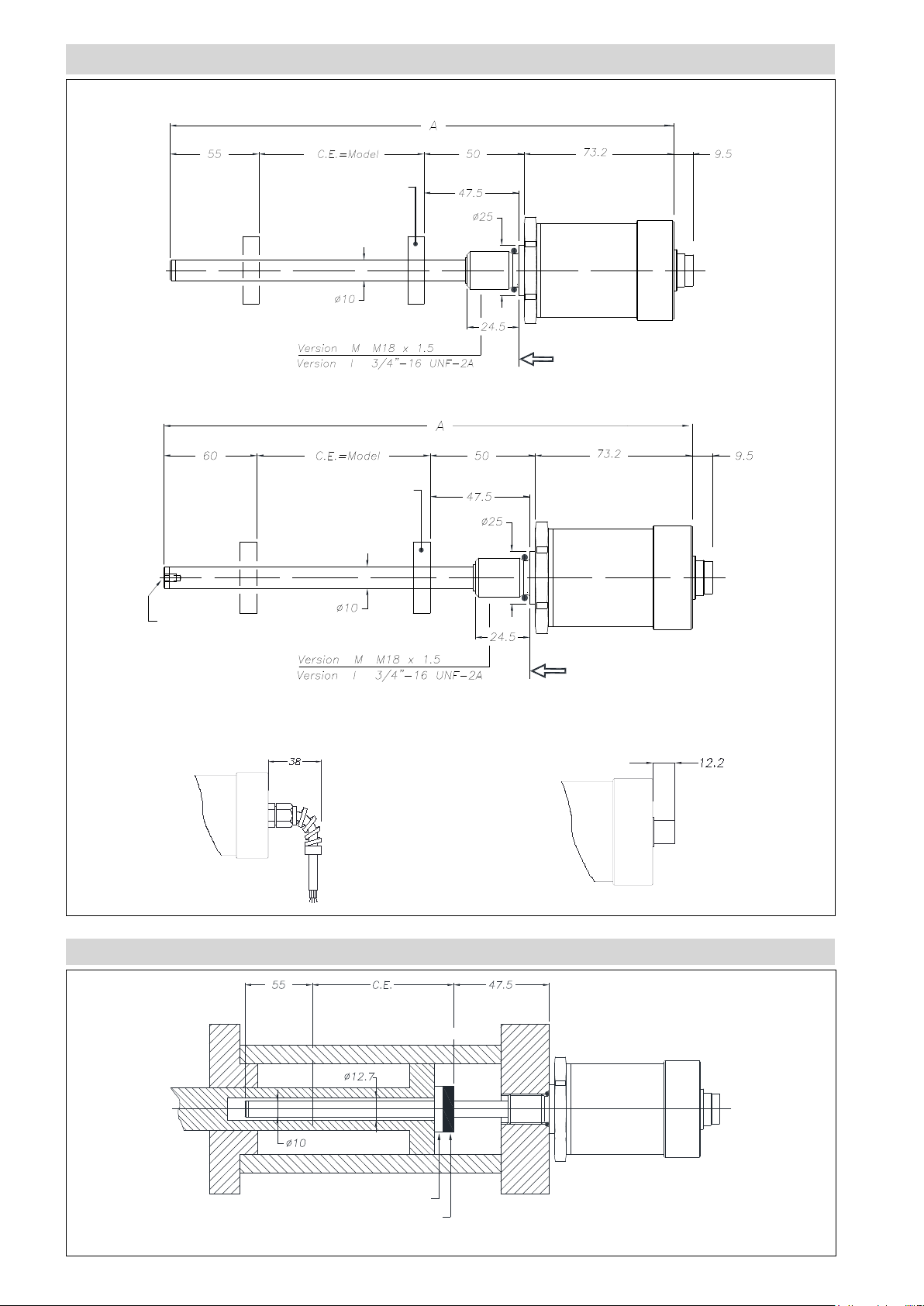
MECHANICAL DIMENSIONS
Floating magnet
Strokes from 50 to 1000 mm
no active zone no active zone
Strokes from 1100 to 4000 mm
no active zone no active zone
Floating magnet
Installation surface
Floating magnet
M4 thread
prof. 6
WRA-A-F/R cable output WRA-A-A/B/C/H connector output
MOUNTING INSIDE A CYLINDER
no active
zone*
no active
zone
Installation surface
Non-magnetic spacer
* for stroke up to 1000 mm (included) – over 1000 mm, the non-active zone becomes 60 mm because the tip includes a M4 threaded hole
Page 3

INSTALLATION INSIDE A CYLINDER
1
THREAD M18x1,5
The sealing surface must be free from scratches
longitudinal or spiral
Ro 1.6 μm for sealing with NON-pulsating pressure
Ro 0.8 μm for seals with pulsating pressure
Suggested o-ring:
PARKER 6-349 15,4x2,1
Material: Viton 90° Shore-A
Mixes: PARKER N552-90
1
THREAD 3/4”-16UNF
The sealing surface must be free from scratches
longitudinal or spiral
Ro 1.6 μm for sealing with NON-pulsating pressure
Ro 0.8 μm for seals with pulsating pressure
Suggested o-ring:
PARKER 3-908 16,36x2,21
Material: Viton 90° Shore-A
Mixes: PARKER N552-90
ELECTRICAL CONNECTIONS
Output WRA-A-A Output WRA-A-B Output WRA-A-C(***) Output WRA-A-H Output WRA-A-F/R
CONNECTORS CABLES OPTIONAL CABLES
Function WRA-A-A WRA-A-B WRA-A-C WRA-A-H WRA-A-F/R CAV00_ CAV01_/CAV02_
5 pin M12 6 pin M16 8 pin M16 8 pin M12
Standard
cables
Output 1 (position)
0...10V
4...20mA
1 1 5 (1*) 5 Grey Green Brown
0...20mA
GND Output 1 (0V) 2 2 2 1 Pink Yellow White
Output 2
(inverse position)
10...0V
3 3 3 3 Yellow Pink Blue
20...4mA
20...0mA
GND Output 2 (0V) 2 4 6 2 Green Grey White
Power supply + 5 5 7 7 Brown Brown Grey
Power supply GND 4 6 8 6 White Blue Black
n.c. - - 4 4 - Red n.c. - - 1 (*5) 8 - White -
Temperatura ratings ** -25+80 °C -30+85 °C -30+85 °C -30+85 °C
(*) = per versione 4...20mA / 0...20mA
(**) The operating temperature ranges, except where expressly indicated, are also applicable in the UL scope.
(***) Not available with UL certification.
-30+80 °C /
-30+75 °C
Pre-assembled cable 8 pin WRA-A-H
Pre-assembled cable 5 pin WRA-A-A
-25+80 °C -25+80 °C
Page 4

GROUNDING WRA-A
Connector ouput WRA-A-A/B/C/H Cable output WRA-A-F/R
Cable shield
Internal electronic cover
(DC ground, isolated from the machine group)
Metallic connector
(machine ground)
ANALOG OUTPUT
0...10V
10...0V
4...20mA
20...4mA
0...20mA
20...0mA
Transducer element
(machine ground)
The signal is proportional to
the position of the magnet
max
0
Cable shield
(machine ground)
U/I
mm
Transducer element
(machine ground)
Internal electronic cover
(DC ground, isolated from the machine group)
Cable holder
(isolated)
The magnetostrictive transducers of the WRA-A
series supply a direct analogue output in voltage
(0...10Vdc) and current (4...20mA and 0...20mA).
All the outputs can have reverse action (10...0Vdc;
20...4ma; 20...0mA).
The outputs are direct, no signal conditioning is
required if they are interfaced with a controller or
measuring instrument.
ORDER CODE
Position
transducer
Analog output A
Output Connector
M12 5 pin output connector A
6 pin DIN 45322 output
connector
8 pin DIN 45326 output
connecto
M12 8 pin output connector H
PVC output cable F
PUR output cable higth flexibility R
MODEL
Output
0...10, 10...0 Vcc A
4...20, 20...4 mA E
0...20, 20...0 mA G
W R A A 1
0 0 0 0
X X X X S 0 X X
Cable lengths
Output F/R 1 mt 00
2 mt 02
3 mt 03
B
C
4 mt 04
5 mt 05
10 mt 10
15 mt 15
Output A/B/C/H 00
Thread
M 18x1.5 (standard) M
3/4” - 16UNF I
Included in the supply
- Series WR position transducer
- OR 15.4 x 2.1 thread M18 x 1.5 cod: GUA064
- OR 16.36 x 2.21 thread 3/4” -16 UNF cod: GUA065
Magnetic cursors must be ordered separately
Ex.: WRA-A-B-0400-A-1 0000XXXXS00M0XX
Transducer model WRA-A, analog output, B connector, model 400mm,
0...10Vdc output , thread M18x1,5
Mechanical and/or electrical characteristics differing
from those in the standard version may be arranged on
request.
Page 5

FLOATING CURSOR
Cable camp
Cable camp
P C
U R
Cursors
Cursor Diameter 32.8 095
Cursor Diameter 32.8 with 90° slit 096
Cursor Diameter 25.4 097
Floating cursor for liquids with hole diameter 12 098
The PCUR095 is supplied with:
N° 8 Brass nuts M4
N° 8 Brass washers D4
N° 4 Brass screws M4x25
The PCUR096 is supplied with:
N° 4 Brass nuts M4
N° 4 Brass washers D4
N° 2 Brass screws M4x25
Dimensions A B C D Thickness
PCUR095
32.8 13.5 23.9
-
7.9PCUR096 11
PCUR097 25.4 13.5 -
Model PCUR098
Length A mm 52.4
Diameter B (hole) mm 12
Diameter C mm 44
Material AISI 316
PCUR095 PCUR096
PCUR097 HEIGHT DETECTION POSITION
Note: PCUR098 is supplied with kit PKIT036 for floating cursor
for liquids.
OPTIONAL CONNECTORS
For WRA-A-A and WRA-A-H, M12 thread connector
CON031 and CON041 for 5 pin output (WRA-A-A)
CON035 and CON042* for 8 pin output (WRA-A-H)
CON117 for 8 pin output (WRA-A-H)
for ø6.5 cable
Cable camp
for ø6 - ø8 cable
CON031
CON035
IP67 - IEC 48B
CON041
CON042/CON117
IP67
For WRA-A-B and WRA-A-C, M16 thread connector
CON021, CON022* and CON023 for 6 pin output (WRA-A-B)
CON026, CON027 and CON028 for 8 pin output (WRA-A-C)
CON118 for 6 pin output (WRA-A-B)
Connector extraction length 10mm
for ø5 cable
CON021
CON026
IP40 - EMC
Cable camp
ø6 - ø8
cable
for
CON022/CON118
CON027
IP67 - EMC
Cable camp
ø5 - ø8
for
cable
CON023
CON028
IP67 - EMC
Temperatura ratings
CON031/CON035 CON041 CON042/CON117 CON021/CON026 CON022/CON018/CON027 CON023/CON028
-30+85 °C -25+85 °C -30+85 °C -30+85 °C -30+85 °C -30+85 °C
* Not available with UL certification.
Note:
1. The IP rating specified in this document normally applies with the suitable female connector plugged-in and properly wired.
2. I valori nominali di temperatura, eccetto dove espressamente indicato, sono da ritenersi applicabili anche in ambito UL
3. Per i cavi di estensione delle applicazioni cULus, si consiglia l’utilizzo di un cavo a 6 poli 26AWG Style 2464.
Page 6

Approx. 50
The cable sheath is
connected to the
connector
Approx. 36
The cable sheath is
connected to the connector
OPTIONAL OUTPUT CABLES
PRE-ASSEMBLED CABLE WITH STRAIGHT CONNECTOR PRE-ASSEMBLED CABLE WITH 90° CONNECTOR
5-pin cable code WRA-A-A
Lenght “L”
2 mt CAV011 CAV021
5 mt CAV012 CAV022
10 mt CAV013 CAV023
15 mt CAV015 CAV024*/CAV280
* Not available with UL certication.
Straight cable Cable to 90°
CODE
8-pin cable code WRA-A-H
Lenght “L”
2 mt CAV002 CAV005
5 mt CAV003 CAV006
10 mt CAV004*/CAV281 CAV007
15 mt CAV009*/CAV282 CAV008
Straight cable Cable to 90°
CODE
ACCESSORIES
Non-magnetic spacer for mounting PCUR022 cursor CUR022
Sensors are manufactured in compliance with:
- EMC 2014/30/EU compatibility directive
- RoHS 2011/65/EU directive
GEFRAN spa reserved the right to make aesthetic or functional changes at any time and without notice.
DTS_WRA-A_07-2019_ENG
 Loading...