

Page 1
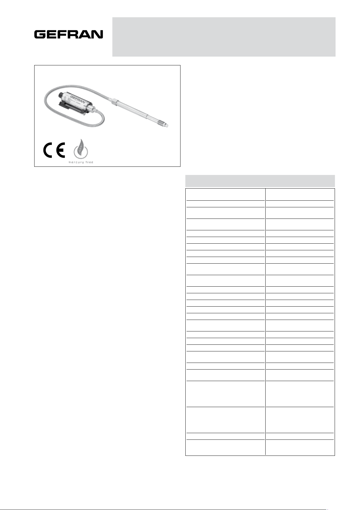
OIL FILLED MELT PRESSURE TRANSMITTERS
WE SERIES Output 4...20mA
The WE series of Gefran, are pressure transmitters for
using in High temperature environment.
The main characteristic of this series is the capability to
read temperature of the media up to 315°C.
The constructive principle is based on the hydraulic trasmission of the pressure.
The fluid-filled system assures the temperature stability.
The phisical measure is transformed in a electrical measure by means the strain-gauge technology.
MAIN FEATURES
• Pressure ranges from:
0-35 to 0-1000 bar / 0-500 to 0-15000 psi
• Accuracy: < ±0.25% FSO (H); < ±0.5% FSO (M)
•Fluid-filled system for temperature stability
•Oil filling meets FDA requirements CFR 178.3620 and
CFR 172.878
•Oil filling volume:
WE0 (30mm3); WE1, WE2, WE3 (40mm3)
•1/2-20UNF, M18x1.5 standard threads; other types avai-
lable on request
• Other diaphragms available on request
• Autozero function on board / external option
• Drift Autocompensation function (SP version)
• 17-7 PH corrugated diaphragm with GTP+ coating for
ranges below 100 bar-1500 psi
GTP+ (advanced protection)
Coating with high resistance against corrosion, abrasion
and high temperature
AUTOZERO FUNCTION
All signal variations in the absence of pressure can be eliminated by using the Autozero function.
This function is activated by closing a magnetic contact
located on the transmitter housing.
The procedure is permitted only with pressure at zero.
AUTOCOMPENSATES INFLUENCE OF MELT
TEMPERATURE
Thanks to internal self-compensation, the WSP series
transmitter cancels the effect of pressure signal variation
caused by variation of Melt temperature.
This reduces at the minimum the read error caused by
heating of the filling fluid (typical of all sensors built with
“filled” technology).
TECHNICAL SPECIFICATIONS
Accuracy (1)
Resolution
Measurement range
Maximum overpressure
(without degrading performances)
Measurement principle
Power supply
Maximum current absorption
Insulation resistance (at 50Vdc)
Output signal Full Scale (FSO)
Zero balance
(tollerance ± 0.25% FSO)
Zero signals adjustment
(tollerance ± 0.25% FSO)
Span adjustment within ± 5% FSO
Maximum allowed load
Response time (10...90% FSO)
Output noise (RMS 10-400Hz)
Calibration signal
Output short circuit ingress and reverse
polarity protection
Compensed temperature range
Operating temperature range
Storage temperature range
Thermal drift in compesated range:
Zero / Calibration / Sensibility
Diaphragm maximum temperature
Zero drift due to change in process
temperature (zero)
Zero drift temperature for
Autocompensated version (SP) within
the temperature range 20°C-315°C
inclusive the drift temperature of the
housing
Standard Material in contact
with process medium
Thermocouple (model WE2)
Protection degree
(with 6-pole female connector)
H <±0.25%FSO (100...1000 bar)
M <±0.5%FSO (35...1000 bar)
0..500 to 0..15000psi
1.5 x FS above 500bar/7500psi
< 0.005 bar/°C 100 ≤ p < 500 bar
0.0022 %FS/°C p ≥ 500 bar
Diaphragm:
• 17-7PH corrugated diaphragm
with GTP+
Stem
• 17-4 PH
STD: type “J” (isolated junction)
Infinite
0..35 to 0..1000bar
2 x FS
Extensimetric
10...30Vdc
32mA
>1000 MOhm
20mA
4mA
“Autozero” function
See Manual
See diagram
~ 1ms
< 0.025% FSO
80% FSO
YES
0...+85°C
-30...+105°C
-40...+125°C
< 0.02% FSO/°C
315°C / 600°F
< 0.04 bar/°C
IP65
FSO = Full scale output
(1) BFSL method (Best Fit Straight Line): includes combined effects of NonLinearity, Hysteresis and Repeatability.
Page 2
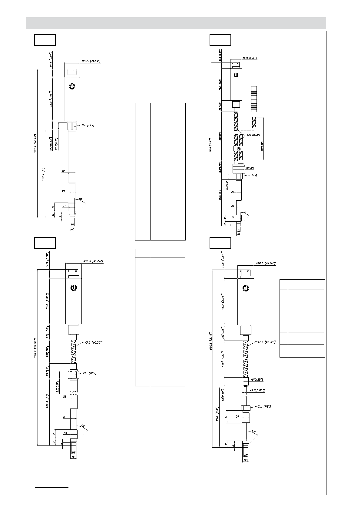
MECHANICAL DIMENSIONS
WE0
D1
D2
D3
D4
D5
A
B
C
WE2
1/2 - 20UNF
ø7.8 -0.05
[ ø0.31” -0.002 ]
ø10.5 -0.025
[ ø0.41” -0.001 ]
ø10.67
[ ø0.42” ]
ø12.7
[ ø0.5” ]
5.56 -0.26
[ 0.22” -0.01 ]
11.2
[ 0.44” ]
15.74
[ 0.62” ]
Ch
[Hex]
16
[ 5/8” ]
WE1 WE3
D1
M18x1.5
[ ø0.394” -0.002 ]
[ ø0.63” -0.003 ]
[ ø0.63” -0.016 ]
A
[ 0.24” -0.01 ]
B
[ 0.58” -0.016 ]
C
ø10 -0.05
ø16 -0.08
ø16 -0.4
ø18
[ ø0.71” ]
6 -0.26
14.8 -0.4
19
[ 0.75” ]
19
[ 3/4” ]
D2
D3
D4
D5
Ch
[Hex]
Exposed
capillary
D1 1/2-20UNF
D2 .307/.305”
[7.80/7.75mm]
D3 .414/.412”
[10.52/10.46mm]
A .125/.120”
[3.18/3.05mm]
B .318/.312”
[8.08/7.92mm]
C .81”
[20.6mm]
NOTE : dimensions refer to rigid stem length option “4” (153 mm – 6”)
WARNING : For installation use a maximum tightening torque of 56 Nm(500 in-lb)
Page 3

42 [1.65"]
ELECTRICAL CONNECTIONS
CURRENT OUTPUT (4...20mA, two wires)
Supply voltage
(10...30Vdc)
Signal
(4...20mA)
Calibration shunt
SUPPLY VOLTAGE
6 pin connector
VPT07RA10-6PT2
(PT02A-10-6P)
8 pin connector
PC02E-12-8P Bendix
CONTROLLER
AMPL./CONV.
LOAD RESISTANCE Rl
MAGNETIC
AUTOZERO
6-pin 8-pin
+
n.c.
n.c.
A
C
-
B
D
E - F
n.c.
Shield drain wire is tied to
connector via cable clamp
B
A
D
C
E - F
G - H
Supply voltage
(10...30Vdc)
Signal
(4...20mA)
Autozero
AUTOZERO FUNCTIONLOAD DIAGRAM
EXTERNAL
AUTOZERO
6-pin 8-pin
+
n.c.
n.c.
A
C
-
B
D
E - F
n.c.
The Autozero function
is activated through a
magnetic contact (external magnet supplied with
the sensor).
See the manual for a
complete Autozero function explanation.
B
A
D
C
E - F
G - H
The diagram shows the optimum ratio between the
load and supply voltage of the 4...20mA transmitter.
For a correct use, choose any combination of load
resistance and supply voltage, in the shaded area.
ACCESSORIES
Connectors
6-pin mating connector (IP65 protection degree) CON300
8-pin mating connector CON307
Extension cables
6-pin connector with 8m (25ft) cable C08WLS
6-pin connector with 15m (50ft) cable C15WLS
6-pin connector with 25m (75ft) cable C25WLS
6-pin connector with 30m (100ft) cable C30WLS
8-pin connector with 8m (25ft) cable E08WLS
8-pin connector with 15m (50ft) cable E15WLS
8-pin connector with 25m (75ft) cable E25WLS
8-pin connector with 30m (100ft) cable E30WLS
Other lengths consult factory
Accessories
Mounting bracket SF18
Dummy plug for 1/2-20UNF SC12
Dummy plug for M18x1.5 SC18
Drill kit for 1/2-20UNF KF12
Drill kit for M18x1.5 KF18
Cleaning kit for 1/2-20UNF CT12
Cleaning kit for M18x1.5 CT18
Thermocouple for WE2 model
Type “J” (153mm - 6” stem) TTER 601
Cable color code
6 wires
Conn. Wire
A Red
B Black
C White
D Green
E Blue
F Orange
Cable color code
8 wires
Conn. Wire
A White
B Red
C Green
D Black
E Blue
F Orange
G n.c.
H n.c.
Page 4

ORDER CODE
6 pin 6
8 pin 8
psi
500
P05C
P75D
750
SP
-
E
0
1
2
3
H
Autocompensation (*)
Standard
(*) available for ranges > to 100bar
(*) not available for WE3 version
OUTPUT SIGNAL
4...20mA
CONFIGURATION
Rigid stem
Rigid stem + flexible
With thermocouple
Exposed capillary
CONNECTOR
Standard
ACCURACY CLASS
(ranges ≥ 100 bar/1500 psi)
bar
3550B35U
70 B07D
100 B01C
200
350 B35D
500 B05C
700
1000 B01M
0.25% FSO
0.5% FSO M
RANGE
B05D
1000 P01M
1500 P15C
B02C
B07C
3000 P03M
5000 P05M
7500 P75C
10000 P10M
15000 P15M
W
000
000= Standard version
Special or customized versions
available on request
E
External autozero
Magnetic autozero-
FLEXIBLE LENGTH
(mm / inches) (*)
Standard (WE0)
0
none
Standard (WE1, WE2)
D
457mm
610mmE
760mmF
Standard (WE3)
711mmL
Available on request
A
76mm
B
152mm
C
300mm
RIGID STEM LENGTH
(mm / inches) (*)
Standard (WE0, WE1, WE2)
4
153mm
318mm5
Standard (WE3)
none0
Available on request
1
38mm
2
50mm
3
76mm
6
350mm
400mm
7
8
456mm
(*) max combined stem/flexible
length is 914mm - 36”
18”
24”
30”
28”
3”
6”
12”
6”
12.5”
1.5”
2”
3”
14”
16”
18”
THREAD
Standard
Examples
WE2-6-M-B07C-1-4-D-000
Melt pressure transmitter with type “J” thermocouple, 4...20mA output, 6-pin
connector, 1/2-20UNF thread, 700 bar full scale, 0,5% accuracy class, 153 mm
(6”) rigid stem, 457mm (18”) flexible capillary.
WSPM0-6-M-P03M-1-4-0-000
Melt pressure transmitter autocompensated version, rigid stem, 4...20mA output,
6-pin connector, 1/2-20UNF thread, 3000 psi full scale, 0,5% accuracy class,
153 mm (6”) rigid stem.
Sensors are manufactured in compliance with:
- EMC compatibility directive
- RoHS directive
Electrical installation requirements and Conformity certificate are available on our web site: www.gefran.com
1
1/2 - 20 UNF
M18 x 1.54
GEFRAN reserves the right to make any kind of design or functional modification at any moment without prior notice.
DTS_WE_02-2017_ENG
 Loading...