

Page 1
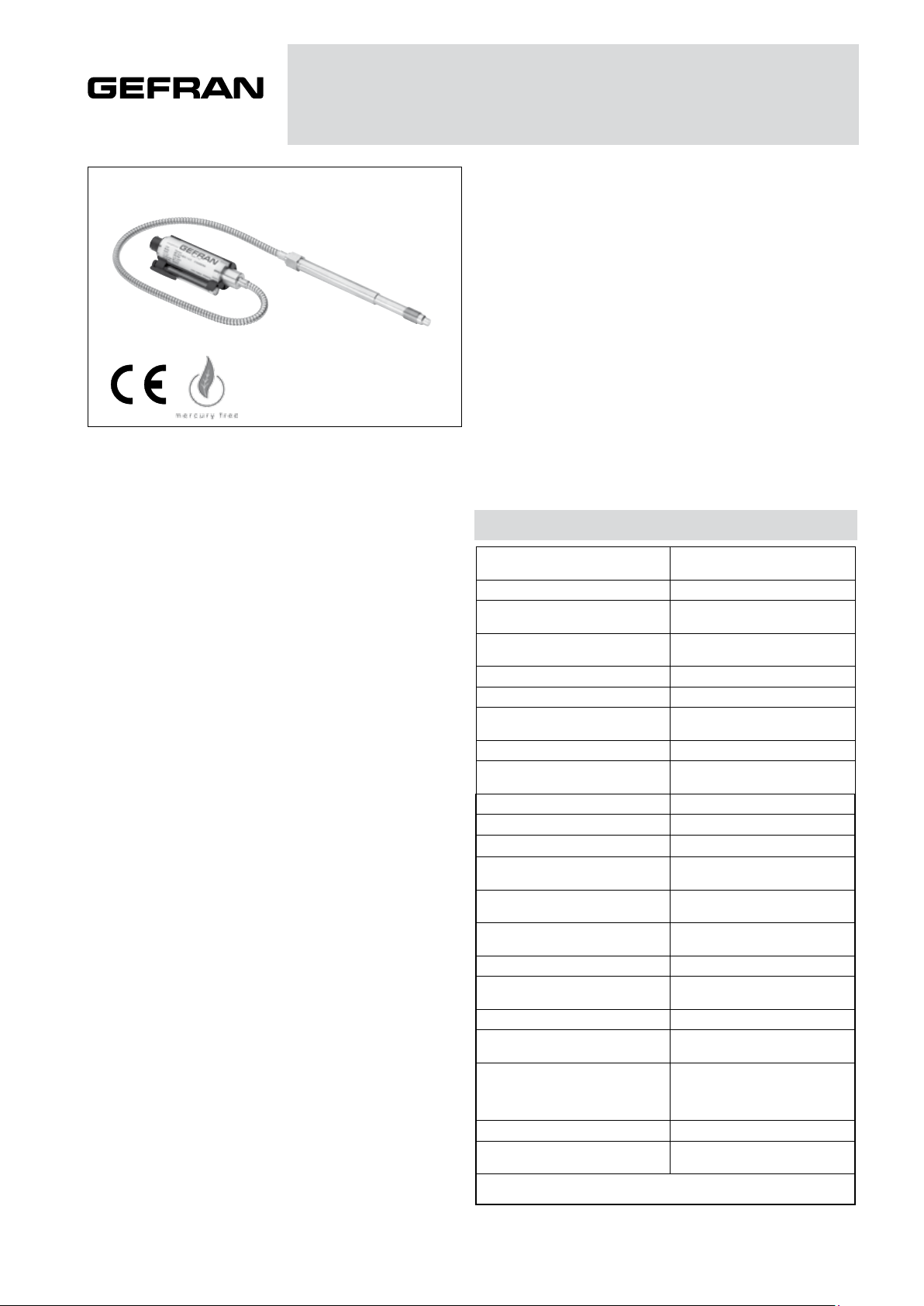
OIL FILLED MELT PRESSURE TRANSMITTERS
WE PERFORMANCE LEVEL ‘c’ SERIES
Output 4...20mA
The WE Performance Level ‘c’ series of Gefran, are
pressure transmitters for using in High temperature environment.
The main characteristic of this series is the capability to
read temperature of the media up to 315°C.
The constructive principle is based on the hydraulic trasmission of the pressure.
The fluid-filled system assures the temperature stability.
The phisical measure is transformed in a electrical measure by means the strain-gauge technology.
MAIN FEATURES
• Pressure ranges from:
0-17 to 0-1000 bar / 0-250 to 0-15000 psi
• Accuracy: < ±0.25% FSO (H); < ±0.5% FSO (M)
•Fluid-filled system for temperature stability
•Oil filling meets FDA requirements CFR 178.3620 and
CFR 172.878
•Oil filling volume:
WE0 (30mm3); WE1, WE2, WE3 (40mm3)
•1/2-20UNF, M18x1.5 standard threads; other types avai-
lable on request
• Other diaphragms available on request
• Autozero function on board / external option
• 17-7 PH corrugated diaphragm with GTP+ coating
GTP+ (advanced protection)
Coating with high resistance against corrosion, abrasion
and high temperature
AUTOZERO FUNCTION
All signal variations in the absence of pressure can be eliminated by using the Autozero function.
This function is activated by closing a magnetic contact
located on the transmitter housing.
The procedure is permitted only with pressure at zero.
TECHNICAL SPECIFICATIONS
Accuracy (1)
Resolution 16 bit
Measurement range
Maximum overpressure
(without degrading performances)
Measurement principle Extensimetric
Power supply 13...30Vdc
Maximum current absorption
Output signal Full Scale FSO 20mA
Zero balance
(tollerance ± 0.25% FSO)
Response time (10...90% FSO) 8ms
Output noise (RMS 10-400Hz) < 0.025% FSO
Calibration signal 80% FSO
Power supply polarity reverse
protection
Compensed temperature range
housing
Operating temperature range
housing
Storage temperature range housing -40...+125°C
Thermal drift in compesated range:
Zero / Calibration / Sensibility
Diaphragm maximum temperature 315°C / 600°F
Zero drift due to change in process
temperature (zero)
Standard material in contact
with process medium
Thermocouple (model WE2) STD : type “J” (isolated junction)
Protection degree
(with 6-pole female connector)
FSO = Full scale output : (1) BFSL method (Best Fit Straight Line): includes combined
effects of Non-Linearity, Hysteresis and Repeatability.
H <±0.25%FSO (100...1000 bar)
M <±0.5%FSO (35...1000 bar)
0..17 a 0..1000bar
0..250 a 0..15000psi
2 x FS
1.5 x FS oltre i 500bar/7500psi
23mA
(40mA with relay optional)
4mA
YES
0...+85°C
-30...+85°C
< 0.02% FSO/°C
< 0.04 bar/°C
Diaphragm:
• 17-7 PH corrugated diaphragm
with GTP+
Stem: • 17-4 PH
IP65
Page 2
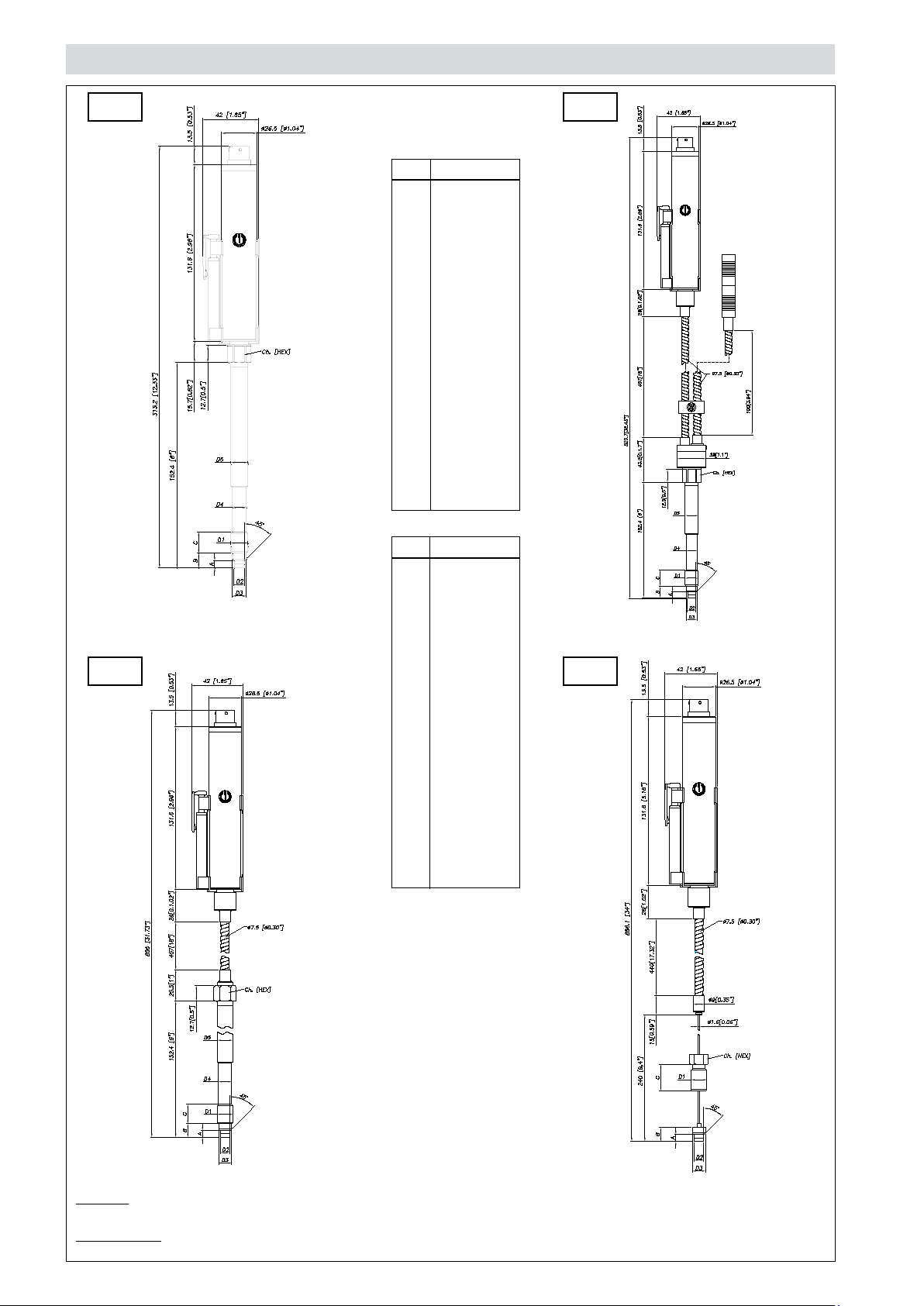
MECHANICAL DIMENSIONS
WE0
D1
D2
D3
D4
D5
A
B
C
Ch
[Hex]
D1
D2
WE2
1/2 - 20UNF
ø7.8 -0.05
[ ø0.31” -0.002 ]
ø10.5 -0.025
[ ø0.41” -0.001 ]
ø10.67
[ ø0.42” ]
ø12.7
[ ø0.5” ]
5.56 -0.26
[ 0.22” -0.01 ]
11.2
[ 0.44” ]
15.74
[ 0.62” ]
16
[ 5/8” ]
M18x1.5
ø10 -0.05
[ ø0.394” -0.002 ]
WE1
D3
D4
D5
A
B
C
Ch
[Hex]
ø16 -0.08
[ ø0.63” -0.003 ]
ø16 -0.4
[ ø0.63” -0.016 ]
ø18
[ ø0.71” ]
6 -0.26
[ 0.24” -0.01 ]
14.8 -0.4
[ 0.58” -0.016 ]
19
[ 0.75” ]
19
[ 3/4” ]
WE3
NOTE : dimensions refer to rigid stem length option “4” (153 mm – 6”)
WARNING : For installation use a maximum tightening torque of 56 Nm (500 in-lb)
Page 3
SELF DIAGNOSTICS
0
100
200
300
400
500
600
700
800
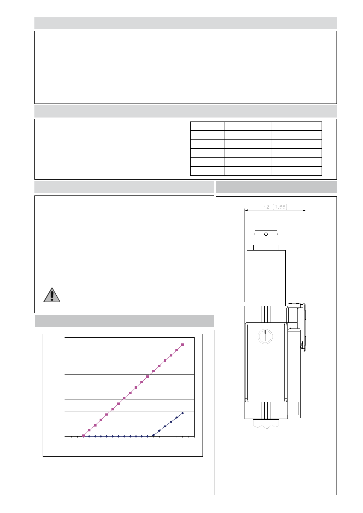
10 11 12 13 14 15 16 17 18 19 20 21 22 23 24 25 26 27 28 29 30 31 32
Vcc (Volt)
R (ohm)
Below the conditions detected by the sensor self-diagnostics:
· Cut cable / device non connected / broken power supply, output <3.6mA
· Pin detachment, output >21mA
· Pressure above 200% of the span, output >21mA
· Voltage monitor in case of overvoltage/undervoltage/voltage variation in the electronics, output <3.6mA
· Program sequence error, output <3.6mA
· Overtemperature on the electronics, output <3.6mA
· Error on the primary element output or on the first amplification stage, output <3.6mA
OPTIONAL RELAY OUTPUT FOR EXCESS PRESSURE PROTECTION
Safety relay characteristics:
· Activation threshold to be defined in the order code
· Rated carry current: 1A
· Rated voltage: 24Vdc ± 20%
· Switch accuracy: 2 x sensor accuracy
· Hysteresis: 2% FSO
SUPPLY OUTPUT RELAY STATUS
OFF - OPEN
ON < X%fs CLOSED
ON > X%fs OPEN
ON output < 3,6mA OPEN
ON output > 21mA OPEN
NAMUR COMPLIANCE
The sensors are tested according to Namur NE21 recommendations.
The same compatibility is valid for the NE43 Namur recommendation
with the following sensor behaviour in case of breakdown:
· Cut cable: breakdown information as the signal is <3,6mA
· Device not connected: breakdown information as the signal is <3,6mA
· Broken power-supply: breakdown information as the signal is <3,6mA
or in case of performance problems:
· most common failures on primary sensors: the signal goes to>21mA
Note: in all the remaining situations, the output signal is always included between 3,6 and 21mA.
Recommendation: the error level set by the customer
(e.g. maximum pressure value) has to be inside the
nominal range.
AUTOZERO FUNCTION
LOAD DIAGRAM
The diagram shows the optimum ratio between load and power supply
for transmitters with 4…20mA output.
For correct function, use a combination of load resistance and voltage
that falls within the two lines in the graph above.
The Autozero function is activated through a
magnetic contact (external magnet supplied
with the sensor).
See the manual for a complete Autozero function explanation.
Page 4
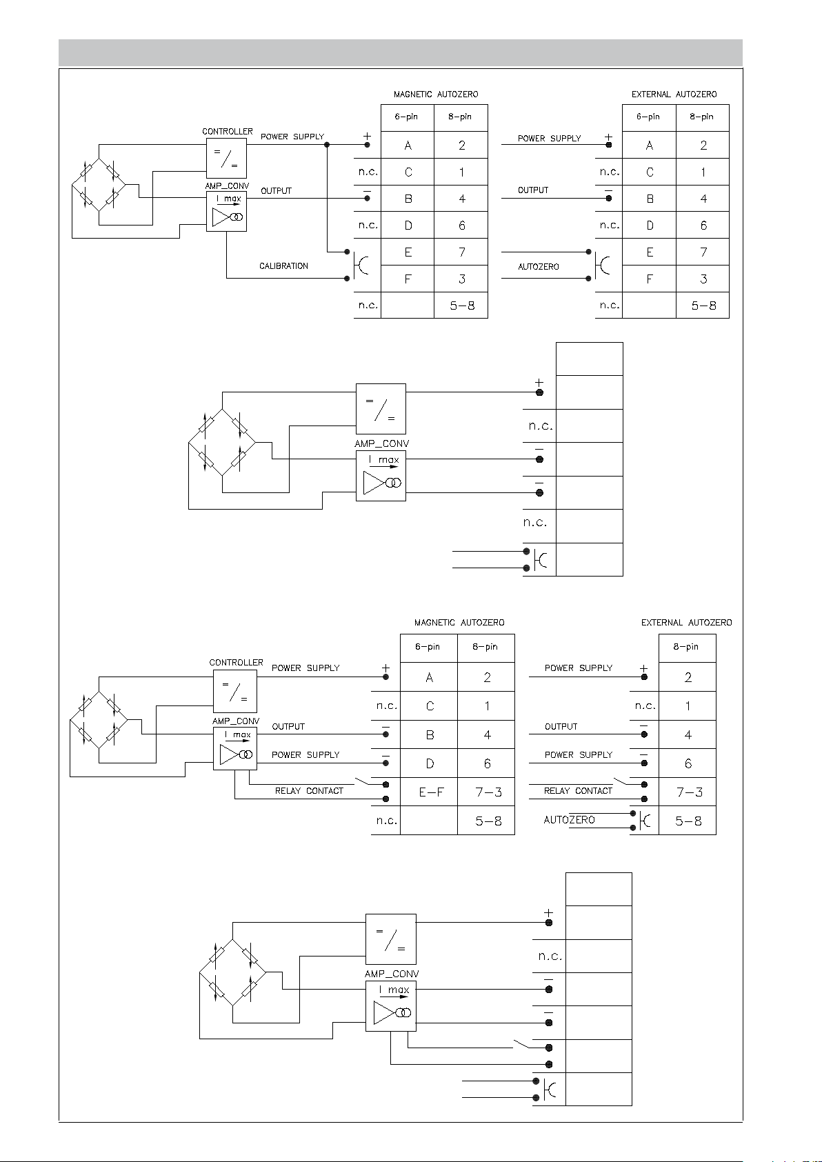
ELECTRICAL CONNECTIONS
EXTERNAL AUTOZERO
EXTERNAL AUTOZERO
CURRENT OUTPUT
CONTROLLER
POWER SUPPLY
7-pin
F
The cable shield is tied to connector via cable clamp
RELAY OUTPUT
OUTPUT
POWER SUPPLY
AUTOZERO
C
B
D-G
A-E
The cable shield is tied to connector via cable clamp
CONTROLLER
POWER SUPPLY
OUTPUT
POWER SUPPLY
RELAY CONTACT
AUTOZERO
7-pin
F
C
B
D-G
A-E
Page 5
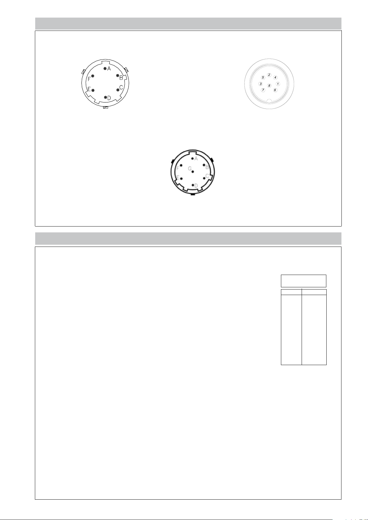
ELECTRICAL CONNECTIONS
6 pin connector VPT07RA10-6PT2
(PT02A-10-6P)
7 pin connector (AMPHENOL) 62IN-5016-10-7P-4-M
8 pin connector (Binder)
M16 DIN/EN45326 (09-0173-00-08)
ACCESSORIES
Connectors
6-pin female connector (IP65 protection degree) CON300
7-pin female connector (IP65 protection degree) CON345
8-pin female connector (IP65 protection degree) CON027
Extension cables
6-pin connector with 8m (25ft) cable C08WLS
6-pin connector with 15m (50ft) cable C15WLS
6-pin connector with 25m (75ft) cable C25WLS
6-pin connector with 30m (100ft) cable C30WLS
8-pin connector with 8m (25ft) cable C08WLS8
8-pin connector with 15m (50ft) cable C15WLS8
8-pin connector with 25m (75ft) cable C25WLS8
8-pin connector with 30m (100ft) cable C30WLS8
Accessories
Mounting bracket SF18
Dummy plug for 1/2-20UNF SC12
Dummy plug for M18x1.5 SC18
Drill kit for 1/2-20UNF KF12
Drill kit for M18x1.5 KF18
Cleaning kit for 1/2-20UNF CT12
Cleaning kit for M18x1.5 CT18
Fixing pen clip PKIT 379
Autozero pen PKIT 378
Thermocouple for WE2 model
Type “J” (153mm - 6” rigid rod) TTER 601
Cable color
code
Conn. Wire
A-2 Red
B-4 Black
C-1 White
D-6 Green
E-7 Blue
F-3 Orange
5 Grey
8 Pink
Page 6
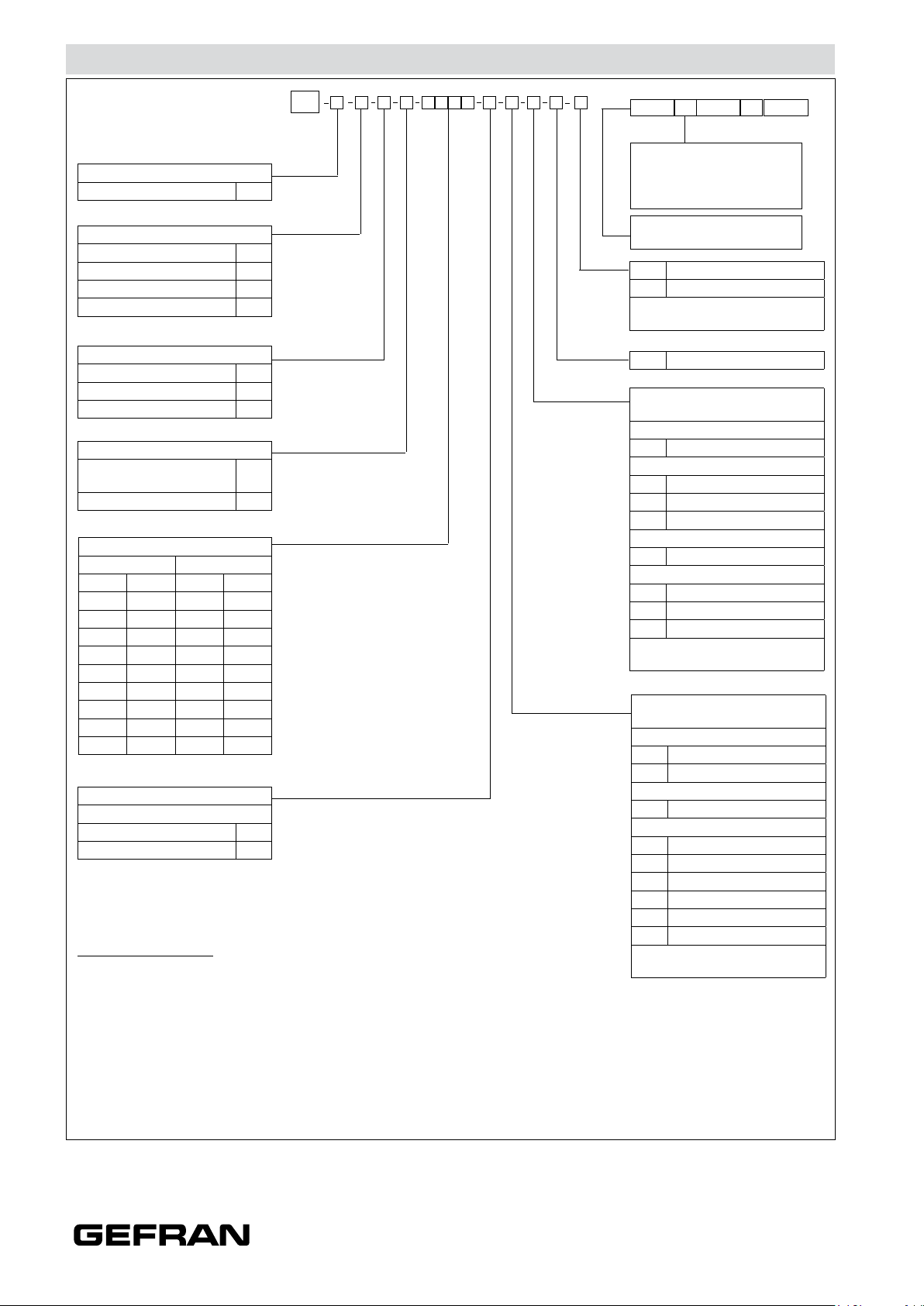
ORDER CODE
W
OUTPUT SIGNAL
4...20mA E
VERSION
Rigid stem 0
Rigid stem + flexible 1
With thermocouple 2
Exposed capillary 3
CONNECTOR
6 pin 6
7 pin 7
8 pin 8
ACCURACY CLASS
(ranges ≥ 100 bar/1500 psi)
0.25% FSO
0.5% FSO M
MEASUREMENT RANGE
bar psi
17 B17U 250 P25D
35 B35U 500 P05C
50 B05D 750 P75D
70 B07D 1000 P01M
100 B01C 1500 P15C
200 B02C 3000 P03M
350 B35D 5000 P05M
500 B05C 7500 P75C
700 B07C 10000 P10M
1000 B01M 15000 P15M
1/2 - 20 UNF 1
M18 x 1.5 4
Example
WE1-6-M-B07C-1-4-D-P
Melt pressure transducer, 4...20mA output, 6-pin connector, 1/2-20 UNF threading, 700
bar pressure range, 0.5% accuracy, 153 mm (6”) rigid rod, 457 mm (18”) flexible rod;
Performance Level=’c’
H
THREAD
Standard
0000
X 000 X 00
Output Relay Version
(activation threshold):
X=no relay B=80%fs
A=70%fs C=90%fs
000= Special executions
E External autozero (*)
- Magnetic autozero
(*) as an alternative to the CAL
function
P Performance Level=’c’
FLEXIBLE ROD LENGTH
(mm/inches) (*)
Standard (WE0)
0 none
Standard (WE1,WE2)
457mm 18”
D
E 610mm 24”
F 760mm 30”
Standard (WE3)
711mm 28”
L
Available on request
76mm 3”
A
B 152mm 6”
C 300mm 12”
(*) max combined stem/flexible
length is 914mm - 36”
RIGID ROD LENGTH
(mm/inches) (*)
Standard (WE0, WE1, WE2)
153mm 6”
4
5 318mm 12.5”
Standard (WE3)
0 none
Available on request
38mm 1.5”
1
2 50mm 2”
3 76mm 3”
6 350mm 14”
7 400mm 16”
8 456mm 18”
(*) max combined stem/flexible
length is 914mm - 36”
Sensors are manufactured in compliance with:
- EMC directive
- RoHS directive
- machinery directive
Electrical installation requirements and Conformity certificate are available on our web site: www.gefran.com
GEFRAN reserves the right to make any kind of design or functional modification at any moment without prior notice.
DTS_WE-PLc_03-2017_ENG
 Loading...