

Page 1
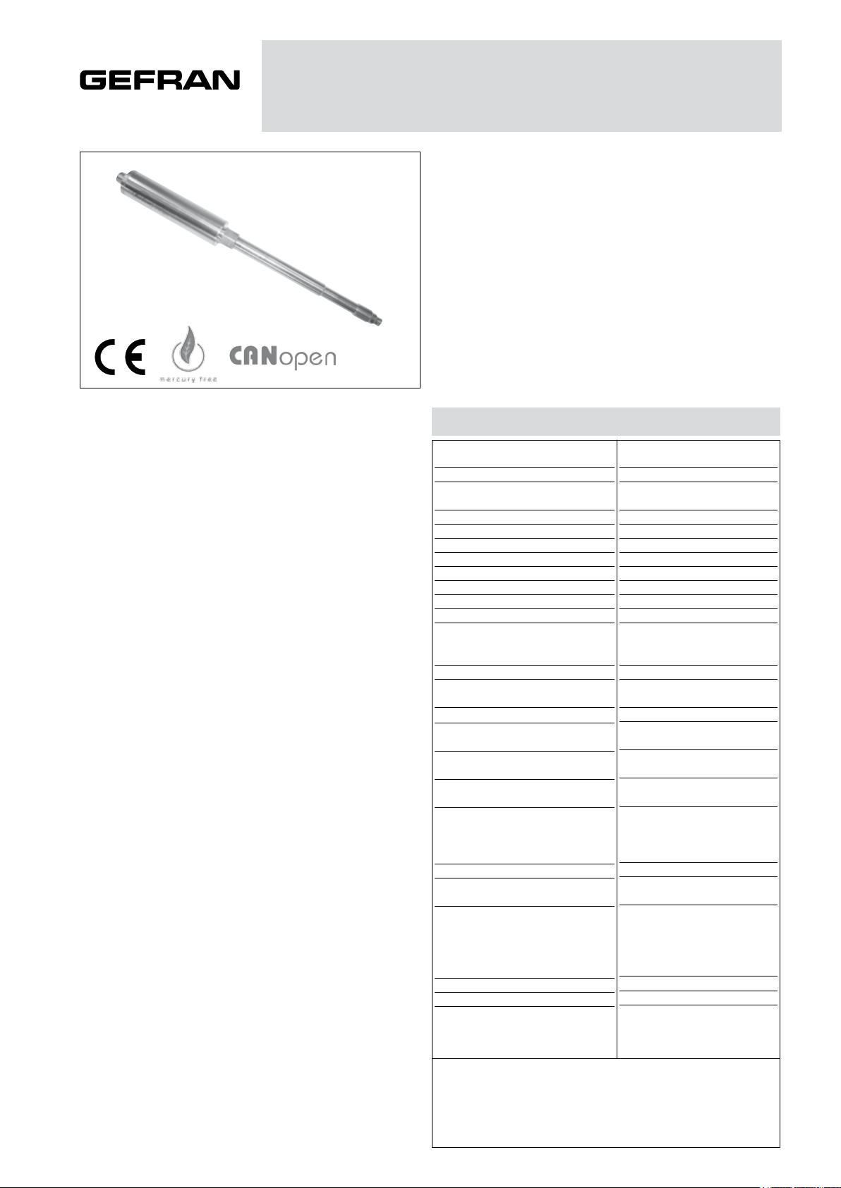
OIL-FILLED MELT PRESSURE TRANSMITTERS
WD SERIES DP404 CAN OPEN digital output
The WD series of Gefran, are pressure transmitters for
using in High temperature environment.
The main characteristic of this series is the capability to
read temperature of the media up to 315°C.
The constructive principle is based on the hydraulic trasmission of the pressure.
The fluid-filled system assures the temperature stability.
The phisical measure is transformed in a electrical measure by means the strain-gauge technology.
MAIN FEATURES
Electrical
• Digital output signal with DP404 CAN OPEN communication protocol
• Transmission frequency (Baud rate): 10 Kbaud to 1Mbaud
(default 500 Kbaud)
• Software selection of Baud rate and ID nodes
• Operation with 1 or 2 settable alarm limits
• “Autozero” for temperature compensation
• Zero and span drift compensation
• 80% FSO calibration signal
• Filling with certifyd oil FDA, CFR178.3620 and
CFR172.878
Mecanical
• Pressure ranges: 0-35 to 0-1000 bar/0-500 to 0-15000 psi
• Precision: < ± 0.25% FSO (H); < ±0.5% FSO (M)
• Extensimetric measurement principle with Wheatstone
jumper
• Hydraulic transmission system to guarantee temperature stability (diathermic oil). Filling with certifyd oil FDA,
CFR178.3620 and CFR172.878
• Quantity of oil contained for model:
series WD0 (30mm3); series WD1,WD2,WD3 (40mm3)
• Standard threading: 1/2-20 UNF, M18x1.5; other versions
on request
• Autozero function by software
• Stainless steel 17-7 PH diaphragm with GTP+ coating
GTP+ (advanced protection)
Coating with high resistance against corrosion, abrasion
and high temperature
TECHNICAL SPECIFICATIONS
Rated precision, including effects of
linearity, repeatability and hysteresis
Sampling
Pressure ranges
Maximum applicable pressure
Measurement principle
Power supply
Typical input
Insulation resistance (at 50Vdc)
Signal at rated pressure (FSO)
Signal at ambient pressure
Calibration of ambient pressure
Signal protocol
Response time (10 at 90% FSO)
Electronic response time
(10 at 90% FSO)
Calibration signal
Protection against overvoltage and
reverse polarity of power supply
Compensated temperature range of
strain Gauge Housing
Maximum temperature range of
strain Gauge Housing
Thermal drift in compensated range;
Zero
Calibration
Sensitivity
Max. diaphragm temperature
Influence due to variation of fluid
temperature (zero)
Standard Material in contact
with process medium
Thermocouple (model WD2)
Protection level
Electrical connections
H < ±0.25%FSO (350…1000 bar)
M < ±0.5%FSO (35…1000 bar)
0-500 to 0-15.000 psi
0-35 to 0-1000 bar
Depends on FSO
Insertion of an offset
DP404 CAN OPEN, with baud
rate selectable from 10K to
1M baud (default 500 Kbaud)
Diaphragm:
• 17-7PH corrugated diaphragm
with GTP+
Stem
• 17-4 PH
STD: Type * J (isolated coupling)
M12 DIN EN 50044 5-pin
16 bit (1)
2 x FSO
Strain gauge
12…40 Vdc
20 mA (2)
>1000 MOhm
0
20 ms
2 ms
80%FSO
YES
0…+85°C
32…+185°F
-30…+105°C
-22…+221°F
<0.02 %FSO/°C
<0.01 %FSO/°F
<0.01 %FSO/°F
315°C (600°F)
0.04bar/°C
30 Psi/100°F
IP65
connector
(1) resolution: 0.01 bar from 35…500bar; 0.1 bar from 700…1000bar;
0.1 psi from 5000…350psi; 1 psi from 7500…15000psi
(2) Conditions: Power supply 24 Vdc
FSO = Full Scale Output (Signal at rated pressure)
Page 2
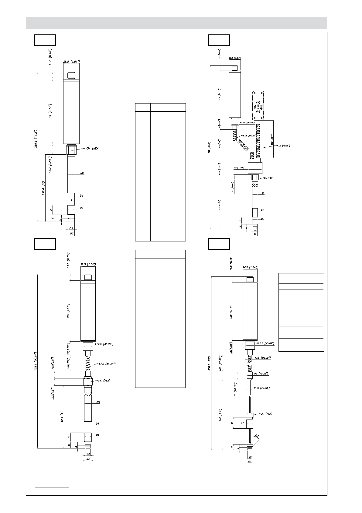
MECHANICAL DIMENSIONS
WD0
D1
D2
D3
D4
D5
A
B
C
WD2
1/2 - 20UNF
ø7.8 -0.05
[ ø0.31” -0.002 ]
ø10.5 -0.025
[ ø0.41” -0.001 ]
ø10.67
[ ø0.42” ]
ø12.7
[ ø0.5” ]
5.56 -0.26
[ 0.22” -0.01 ]
11.2
[ 0.44” ]
15.74
[ 0.62” ]
WD1
Ch
[Hex]
D1
D2
D3
D4
D5
A
B
C
Ch
[Hex]
16
[ 5/8” ]
M18x1,5
ø10 -0.05
[ ø0.394” -0.002 ]
ø16 -0.08
[ ø0.63” -0.003 ]
ø16 -0.4
[ ø0.63” -0.016 ]
ø18
[ ø0.71” ]
6 -0.26
[ 0.24” -0.01 ]
14.8 -0.4
[ 0.58” -0.016 ]
19
[ 0.75” ]
19
[ 3/4” ]
WD3
Exposed
capillary
D1 1/2-20UNF
D2 .307/.305”
[7.80/7.75mm]
D3 .414/.412”
[10.52/10.46mm]
A .125/.120”
[3.18/3.05mm]
B .318/.312”
[8.08/7.92mm]
C .81”
[20.6mm]
NOTE : dimensions refer to rigid stem length option “4” (153 mm – 6”)
WARNING : For installation use a maximum tightening torque of 56 Nm(500 in-lb)
Page 3
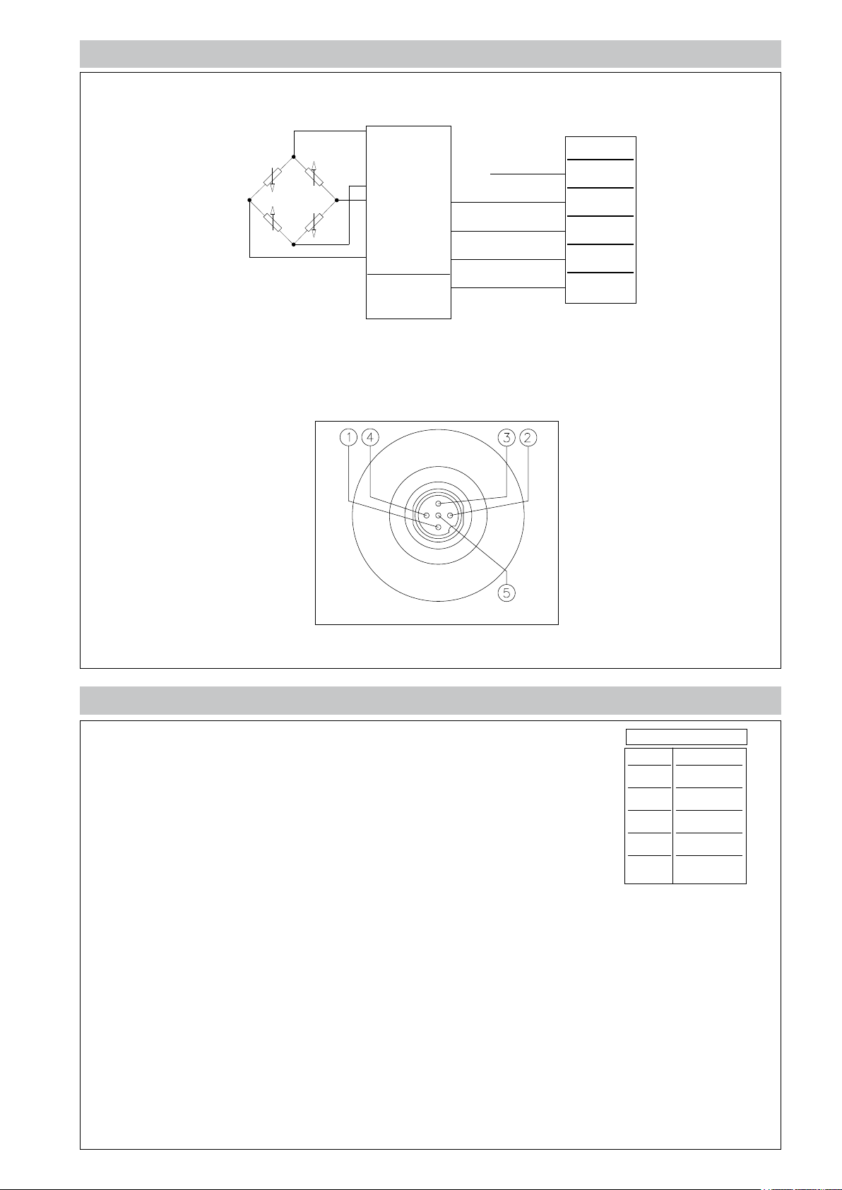
ELECTRICAL CONNECTIONS
Shielding is connected to transducer body. It is advisable to ground it on the instrument side as well.
CAN BUS DP404 DIGITAL OUTPUT
n.c.
Controller
Can Output
power +
power -
Can H
Can L
5-pin
1
2
3
4
5
M12 DIN EN 50044 5-pin connector
ACCESSORIES
Connectors
5 pin female connector (IP65 protection) CON031
Extension cords
5-pin connector with cord length 1 meter (3.3 ft) PCAV161
5-pin connector with cord length 2 meters (7 ft) PCAV162
5-pin connector with cord length 5 meters (17 ft) PCAV163
Other lengths on request
Accessories
Fastening bracket SF18
Protective plug for 1/2 - 20 UNF SC12
Protective plug for M18x1.5 SC18
Punch kit for 1/2-20 UNF KF12
Punch kit for M18x1.5 KF18
Cleaning kit for 1/2-20 UNF CT12
Cleaning kit for M18x1.5 CT18
Cord color code
Conn.
1
2
3
4
5
Wire
n.c.
Red
Black
White
Blue
Page 4

ORDER CODE
OUTPUT SIGNAL
CAN BUS D
CONFIGURATION
Rigid rod
Rigid + flexible rod
With thermocouple
Exposed capillary
CONNECTOR
Standard
5-pin M12 5
PRECISION CLASS
± 0.25%
(ranges ≥100 bar/1500 psi)
± 0.5% M
MEASUREMENT RANGE
bar
3550B35U
B05D
70 B07D
100 B01C
200
B02C
350 B35D
500 B05C
700 B07C
1000 B01M
500
750
1000 P01M
1500 P15C
3000 P03M
5000 P05M
7500
10000 P10M
15000 P15M
psi
0
1
2
3
H
P05C
P75D
P75C
W
000
000= Special executions of the
standard version or custom
versions may be ordered on
request
LENGTH OF FLEXIBLE ROD(*)
(mm / inches)
Standard (WD0)
0
Standard (WD1, WD2)
D
Standard (WD3)
L
On request
A
B
C
LENGHT OF RIGID ROD (*)
(mm / inches)
Standard (WD0, WD1, WD2)*
4
Standard (WD3)
0
On request
1
2
3
6
7
8
THREADING
Standard
1
none
457mm
610mmE
760mmF
711mm
76mm
152mm
300mm
153mm
318mm5
none
38mm
50mm
76mm
350mm
400mm
456mm
1/2 - 20 UNF
M18 x 1.54
18”
24”
30”
28”
3”
6”
12”
6”
12.5”
1.5”
2”
3”
14”
16”
18”
(*) note: max. total length of
rigid/flexible rod is 914 mm-36”
Example
WD0-5-M-B07C-1-4-0-000
Oil-filled melt pressure transducer with Can output, 5-pin connector, 1/2 - 20 UNF
threading, pressure range 700 bar, precision class 0.5%, 153 mm (6”) rigid rod.
WD1-5-M-P03M-1-4-D-000
Oil-filled melt pressure transducer with Can output, 5-pin connector, 1/2 - 20 UNF
threading, pressure range 3000 bar, precision class 0.5%, 153 mm (6”) rigid rod,
457 mm (18”) flexible rod.
Sensors are manufactured in compliance with:
- EMC compatibility directive
- RoHS directive
Electrical installation requirements and Conformity certificate are available on our web site: www.gefran.com
GEFRAN spa reserves the right to make aesthetic or functional changes at any time and without notice.
DTS_WD_04-2017_ENG
 Loading...