

gefran VDI100-2055-KBX-2T, VDI100-4110-KBX-2T, VDI100-1007-KBX-2T, VDI100-3075-KBX-2T, VDI100-4150-KBX-2T Instruction Manual
...Page 1
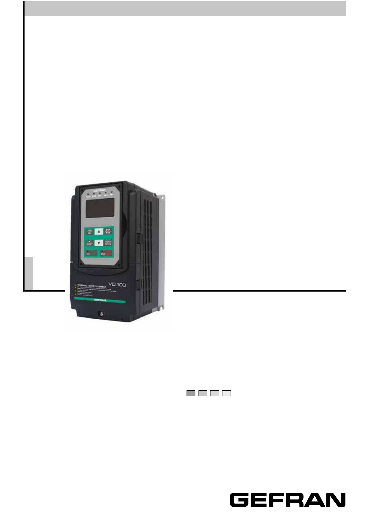
General Purpose
Full Vector Inverter
VDI100
.... Instruction manual
Page 2

Information about this manual
The
VDI100 product is an inverter designed to control a three-phase induction motor and permanent magnet.
Please read this manual carefully to ensure correct operation, safety and to become familiar with the inverter
functions.
The
VDI100 inverter is an electrical / electronic product and must be installed and handled by qualied service
personnel.
Improper handling may result in incorrect operation, shorter life cycle, or failure of this product as well as the
motor.
VDI100 documentation is subject to change without notice. Be sure to obtain the latest editions for use or
All
visit our website at http://www.gefran.com/en/product_categories/93-motion-control
Available Documentation:
VDI100 Start-up and Installation Manual
1.
2.
VDI100 Instruction Manual
Ensure you have sound knowledge of the device and familiarize yourself with all safety information and precautions before proceeding to operate the inverter.
Software version
This manual is updated according the software version V 1.04
The identication number of the software version is indicated on the identication plate of the drive or can be
checked with the par. 13.01.
General information
Note ! In industry, the terms “Inverter”, “Regulator” and “Drive” are sometimes interchanged. In this document, the term “Drive” will be
used.
Before using the product, read the safety instruction section carefully.
Keep the manual in a safe place and available to engineering and installation personnel during the product
functioning period.
Gefran S.p.A has the right to modify products, data and dimensions without notice. The data can only be used
for the product description and they can not be understood as legally stated properties.
Thank you for choosing this Gefran product.
We will be glad to receive any possible information which could help us improving this manual. The e-mail
address is the following: techdoc@gefran.com.
All rights reserved
2 VDI100 • Instruction manual
Page 3

Table of contents
Information about this manual ..................................................................................................................2
Software version .....................................................................................................................................................2
General information ................................................................................................................................................2
1. Safety Precautions ..............................................................................................................................5
1.1. Symbols used in the manual ....................................................................................................................5
1.2. Before Supplying Power to the Inverter /
1.3. Wiring / Câblage .......................................................................................................................................6
1.4. Before Operation / Avant l’opération ........................................................................................................7
1.5. Parameters Setting / Conguration Paramètre ........................................................................................8
1.6. Operation / Opération ...............................................................................................................................8
1.7. Maintenance, Inspection and Replacement / Entretien, Inspection et remplacement .............................9
1.8. Disposal of the Inverter / Mise au rebut du variateur ...............................................................................9
2. Model Description ............................................................................................................................. 11
2.1. Nameplate Data .....................................................................................................................................11
2.2. Inverter Models – Motor Power Rating (HD – Heavy Duty) ...................................................................11
3. Environment and Installation ...........................................................................................................13
3.1. Environment ...........................................................................................................................................13
3.2. Installation ..............................................................................................................................................13
3.3. External View .........................................................................................................................................14
3.4. Warning Labels ......................................................................................................................................16
3.5. Removing the Front Cover and Keypad .................................................................................................16
3.5.1. Standard Type ..........................................................................................................................................................17
3.5.2. Add-onltertype(400VClass:0.75~45kW) ........................................................................................................19
3.6. Wire Gauges and Tightening Torque ......................................................................................................20
3.7. Wiring Peripheral Power Devices ...........................................................................................................21
3.8. General Wiring Diagram .........................................................................................................................24
3.9. User Terminals (Control Circuit Terminals) .............................................................................................24
3.10. Power Terminals .....................................................................................................................................26
3.11. Input / Output Power Section Block Diagram .........................................................................................28
3.11.1. CoolingFanSupplyVoltageSelection(400Vclass) ................................................................................................29
3.12. Inverter Wiring ........................................................................................................................................30
3.13. Input Power and Motor Cable Length ....................................................................................................31
3.14. Motor Cable Length vs. Carrier Frequency ............................................................................................31
3.15. Installing an AC Line Reactor .................................................................................................................31
3.16. Wire Section ...........................................................................................................................................31
3.17. Control Circuit Wiring .............................................................................................................................32
3.18. Inverter Specications ............................................................................................................................34
3.18.1. Powerloss ................................................................................................................................................................36
3.18.2. GeneralSpecications .............................................................................................................................................37
3.19. Inverter Derating Based on Carrier Frequency ......................................................................................38
3.20. Inverter Derating Based on Temperature ...............................................................................................39
3.21. Inverter Derating Based on Altitude .......................................................................................................39
3.22. Inverter Dimensions ...............................................................................................................................40
3.23. Dimensions for Models with
4. Keypad and Programming Functions .............................................................................................45
4.1. LED Keypad (KB-LED-VDI100) ......................................................................................................45
4.1.1. KeypadDisplayandKeys ........................................................................................................................................45
4.1.2. SevenSegmentDisplayDescription ........................................................................................................................46
4.1.3. LEDIndicatorDescription ........................................................................................................................................47
4.1.4. Power-upMonitor .....................................................................................................................................................48
4.1.5. ModifyingParameters/SetFrequencyReference ...................................................................................................49
4.1.6. OperationControl .....................................................................................................................................................50
4.2. LCD Keypad (KB-LCD-VDI100) .............................................................................................................51
4.2.1. KeypadDisplayandKeys ........................................................................................................................................51
4.2.2. KeypadMenuStructure ...........................................................................................................................................52
4.2.3. Notes ........................................................................................................................................................................54
4.3. Parameters .............................................................................................................................................56
4.3.1. Attachment1:Parameters’defaultvalueandupperlimitvalueareadjustedbydifferentinvertersizes .................92
4.3.2. LowVoltageDetectionLevelFunction .....................................................................................................................94
4.4. Description of Parameters ......................................................................................................................95
00-BasicParameters ..............................................................................................................................................................95
01-V/fControlParameters .................................................................................................................................................... 11 2
02-IMMotorParameters ......................................................................................................................................................138
03-ExternalDigitalInputandOutputParameters .................................................................................................................142
04-ExternalAnalogInput/OutputParameter ......................................................................................................................172
05-Multi-SpeedParameters ..................................................................................................................................................182
06-AutomaticProgramOperationParameters .....................................................................................................................186
07-Start/StopParameters .....................................................................................................................................................189
08-ProtectionParameters .....................................................................................................................................................202
09-CommunicationParameters ............................................................................................................................................ 2 11
10-PIDParameters ...............................................................................................................................................................213
11-AuxiliaryParameters ........................................................................................................................................................ 224
12-MonitoringParameters ....................................................................................................................................................239
Avant d’alimenter le variateur ..................................................5
Add-on lter ...............................................................................................43
VDI100 • Instruction manual
3
Page 4

13-MaintenanceParameters ................................................................................................................................................241
14-PLCParameters ..............................................................................................................................................................246
15-PLCMonitoringParameters ............................................................................................................................................247
16-LCDFunctiongroup ........................................................................................................................................................248
17-AutomaticTuningParameters ......................................................................................................................................... 253
18-SlipCompensationParameters.......................................................................................................................................257
19-WobbleFrequencyParameters .......................................................................................................................................260
20-SpeedControlParameters ..............................................................................................................................................262
21-TorqueAndPositionControlParameters ........................................................................................................................271
22-PMMotorParameters .....................................................................................................................................................280
4.4.1. Annexed1:Parameters’defaultandupperlimitvaluesaccordingtotheinvertersizes ........................................283
4.5. Built-in PLC Function ...........................................................................................................................286
4.5.1. BasicCommand .....................................................................................................................................................286
4.5.2. BasicCommandFunction ......................................................................................................................................287
4.5.3. ApplicationFunctions ............................................................................................................................................288
4.6. Modbus Protocol Descriptions .............................................................................................................294
4.6.1. CommunicationConnectionandDataFrame ........................................................................................................294
4.6.2. RegisterandDataFormat ......................................................................................................................................296
4.6.3. ParameterData ......................................................................................................................................................302
5. Check Motor Rotation and Direction .............................................................................................309
6. SpeedReferenceCommandConguration ..................................................................................311
6.1. Reference from Keypad .......................................................................................................................3 11
6.2. Reference from External Analog Signal (0-10V / 4-20mA) ...................................................................3 11
6.3. Reference from Serial Communication RS485 (00-05=3) ...................................................................312
6.4. Reference from Pulse Input (00-05=4) .................................................................................................313
6.5. Reference from two Analog Inputs .......................................................................................................314
6.6. Change Frequency Unit from Hz to rpm ..............................................................................................315
7. OperationMethodConguration(Run/Stop) .............................................................................316
7.1. Run/Stop from the LED/LCD Keypad (00-02=0) .................................................................................316
7.2. Run/Stop from External Switch / Contact or Pushbutton (00-02=1) .....................................................317
7.3. Run/Stop from Serial Communication RS485 (00-02=3) .....................................................................318
8. MotorandApplicationSpecicSettings ......................................................................................319
8.1. Set Motor Nameplate Data (02-01, 02-05) ...........................................................................................319
8.2. Acceleration and Deceleration Time (00-14, 00-15) .............................................................................319
8.3. Torque Compensation Gain (01-10) ..................................................................................................... 320
8.4. Automatic Energy Saving Functions (11-19) ........................................................................................321
8.5. Emergency Stop ...................................................................................................................................322
8.6. Forward and Reverse Jog ....................................................................................................................322
8.7. Direct / Unattended Startup ..................................................................................................................324
8.8. Analog Output Setup ............................................................................................................................324
9. UsingPIDControlforConstantFlow/PressureApplications ...................................................326
9.1. What is PID Control? ............................................................................................................................326
9.2. Connect Transducer Feedback Signal (10-01) ....................................................................................328
9.3. Engineering Units (only for LCD) .........................................................................................................328
9.4. Sleep / Wakeup Function .....................................................................................................................328
10. Troubleshooting and Fault Diagnostics .......................................................................................330
10.1. General ................................................................................................................................................330
10.2. Fault Detection Function ......................................................................................................................330
10.3. Warning / Self-diagnosis Detection Function .......................................................................................333
10.4. Auto-tuning Error ..................................................................................................................................339
10.5. PM Motor Auto-tuning Error ................................................................................................................339
11. Inverter
Accessories and Options .................................................................................................340
11.1. Braking Resistors and Braking Units ....................................................................................................340
11.2. AC Line Reactors .................................................................................................................................341
11.3. Output Choke .......................................................................................................................................342
11.4. Input
EMC Filters .................................................................................................................................343
11.5. Input Current and Fuse Specications .................................................................................................344
11.6. PG Speed Feedback Card ...................................................................................................................345
11.7. Other Options .......................................................................................................................................348
11.8. Communication Options .......................................................................................................................350
Appendix A: Communication Networks ...............................................................................................351
A1.1 RS485 –Network (Modbus) ........................................................................................................................351
A1.2 Probus DP Network ..................................................................................................................................352
Appendix B: UL Instructions .................................................................................................................353
4 VDI100 • Instruction manual
Page 5
1. Safety Precautions
Warning
Important
Warning
Preface
• Ensure you have sound knowledge of the device and familiarize yourself with all safety information and
precautions before proceeding to operate the inverter.
• Please pay close attention to the safety precautions indicated by the warning and caution symbol.
Préface
• Vériez que vous avez une bonne connaissance de l’entraînement et de vous familiariser avec les consignes de sécurité et les précautions avant de procéder à fonctionner le lecteur.
• Prêter attention aux consignes de sécurité indiquées par l’avertissement (Warning) et symbole Attention
(Caution).
1.1. Symbols used in the manual
Indicates a procedure, condition, or statement that, if not strictly observed, could result in personal injury or death.
Indiquelemoded’utilisation,laprocédureetlaconditiond’exploitation.Sicesconsignesnesontpasstrictementrespectées,ilyadesrisquesdeblessurescorporellesoudemort.
Indicates a procedure, condition, or statement that, if not strictly observed, could result in damage to or destruc-
Caution
tion of equipment.
Indiqueetlemoded’utilisation,laprocédureetlaconditiond’exploitation.Sicesconsignesnesontpasstrictementrespectées,ilyadesrisquesdedétériorationoudedestructiondesappareils.
Indicates that the presence of electrostatic discharge could damage the appliance. When handling the boards,
always wear a grounded bracelet.
Indiquequelaprésencededéchargesélectrostatiquesestsusceptibled’endommagerl’appareil.Toujours
porterunbraceletdemiseàlaterrelorsdelamanipulationdescartes.
Indicates a procedure, condition, or statement that should be strictly followed in order to optimize these applications.
Indiquelemoded’utilisation,laprocédureetlaconditiond’exploitation.Cesconsignesdoiventêtrerigoureusementrespectéespouroptimisercesapplications.
Note ! Indicates an essential or important procedure, condition, or statement.
Indique un mode d’utilisation, de procédure et de condition d’exploitation essentiels ou importants
1.2. BeforeSupplyingPowertotheInverter/ Avant d’alimenter le variateur
The main circuit must be correctly wired. For single phase supply use input terminals (R/L1, T/L3) and for three
phase supply use input terminals (R/L1, S/L2, T/L3). Terminals U/T1, V/T2, W/T3 must only be used to connect
the motor. Connecting the input supply to any of the U/T1, V/T2 or W/T3 terminals will cause damage to the
inverter.
Avertissement !
Lecircuitprincipaldoitêtrecorrectementcâblée.Pourlesterminauxmonophasésd’approvisionnementde
l’utilisationdesintrants(R/L1,T/L3)etdetroisbornesd’entréedel’utilisationdel’offredephase(R/L1,S/L2,T/
L3).U/T1,V/T2,W/T3nedoiventêtreutiliséspourconnecterlemoteur.Raccordementdel’alimentationd’entréeàl’undesU/T1,V/T2W/T3oubornesrisqued’endommagerlelecteur.
• To avoid the front cover from disengaging or other physical damage, do not carry the inverter by its cover.
Caution
VDI100 • Instruction manual 5
Support the unit by its heat sink when transporting. Improper handling can damage the inverter or injure
Page 6

personnel, and should be avoided.
Warning
Warning
• To avoid the risk of re, do not install the inverter on or near ammable objects. Install on nonammable
objects such as metal surfaces.
• If several inverters are placed inside the same control panel, provide adequate ventilation to maintain the
temperature below 40°C/104°F (50°C/122°F) without a dust cover) to avoid overheating or re.
• When removing or installing the digital operator, turn off the power rst, and then follow the instructions in
this manual to avoid operator error or loss of display caused by faulty connections.
Attention !
• Pouréviterledétachementducacheavantoud’autresdommagesmatériels,nepassaisirlevariateurpar
soncache.Lorsdutransport,maintenirl’unitéparsondissipateurdechaleur.Evitertoutemanutention
incorrecte,sourcepotentiellededommagescorporelsetmatériels.
• Pourévitertoutrisqued’incendie,nepasinstallerlevariateursurouprèsd’objetsinammables.Installer
levariateursurdessurfacesmétalliquesnoninammables.
• Siplusieursvariateurssontlogésàl’intérieurd’unemêmearmoire,assurerunebonneventilationpour
maintenirunetempératureinférieureà40°C/104°F(50°C/122°F)(sanscache-poussière),pourévitertout
risquedesurchauffeetd’incendie.
• Lorsdeladépose/reposedel’opérateurnumérique,couperd’abordl’alimentationpuissuivrelesinstructionsci-contenuespourévitertouteerreurouperted’afchagedueàdesconnexionsdéfectueuses.
•
This product is sold subject to IEC 61800-3. In a domestic environment this product may cause radio interference in which case the user may need to apply corrective measures.
• Motor over temperature protection is not provided.
Avertissement !
• CesproduitestcommercialiséconformémentàlanormeIEC61800-3.Enmilieurésidentiel,ceproduit
peutprovoquerdesinterférencesradio;danscecas,l’utilisateurdevraentreprendredesactionscorrectives.
• Laprotectioncontrelasur-températuredumoteurn’estpasprévue.
1.3. Wiring /Câblage
•
Always turn OFF the power supply before attempting inverter installation and wiring of the user terminals.
• Wiring must be performed by a qualied personnel / certied electrician.
• Make sure the inverter is properly grounded. (
230V Class: Grounding impedance shall be less than 100Ω.
400V Class: Grounding impedance shall be less than 10Ω.)
• Make sure the inverter is properly grounded. It is required to disconnect the ground wire in the control
board to avoid the sudden surge causing damage on electronic parts if it is improperly grounded.
• RCD is required to be in compliance with the protection norm of B-type leakage current.
• Please check and test emergency stop circuits after wiring. (Installer is responsible for the correct wiring.)
• Never touch any of the input or output power lines directly or allow any input of output power lines to come
in contact with the inverter case.
• Do not perform a dielectric voltage withstand test (megger) on the inverter this will result in inverter damage to the semiconductor components.
Avertissement !
• Coupeztoujoursl’alimentationélectriqueavantdeprocéderàl’installationd’entraînementetlecâblage
desterminauxutilisateurs.
• Lecâblagedoitêtreeffectuéparunpersonnelqualié/électriciencertié.
• Assurez-vousquelelecteurestcorrectementmisàlaterre.(230VClasse:impédancedemiseàlaterre
doitêtreinférieureà100Ω.Classe440V:Impédancedemiseàlaterredoitêtreinférieureà10Ω.)
• Vérierettestermescircuitsd’arrêtd’urgenceaprèslecâblage.(L’Installateurestresponsabledu
câblage.)
• Netouchezjamaisdel’entréeoudelignesélectriquesdesortiepermettantdirectementoutouteentréeou
delignesdepuissancedesortieàvenirencontactavecleboîtierd’entraînement.
6 VDI100 • Instruction manual
Page 7

Caution
Warning
• Nepaseffectueruntestdetenueentensiondiélectrique(mégohmmètre)surlevariateuroucelavaentraînerdesdommagesdelecturepourlescomposantssemi-conducteurs.
• The line voltage applied must comply with the inverter’s specied input voltage. (See product nameplate
section 2.1)
• Connect braking resistor and braking unit to the designated terminals. (See section 3.10)
• Do not connect a braking resistor directly to the DC terminals P (+) and N (-), otherwise re may result.
• Use wire gauge recommendations and torque specications. (See Wire Gauge and Torque Specication in
section 3.6)
• Never connect input power to the inverter output terminals U/T1, V/T2, W/T3.
• Do not connect a contactor or switch in series with the inverter and the motor.
• Do not connect a power factor correction capacitor or surge suppressor to the inverter output.
• Ensure the interference generated by the inverter and motor does not affect peripheral devices.
Attention !
• Latensiond’alimentationappliquéedoitseconformeràlatensiond’entréespéciéeparlelecteur(voirla
sectionsignalétiqueduproduit,ch.2.1).
• Raccorderlarésistancedefreinageetdel’unitédefreinagesurlesbornesassignées(voirch.3.10).
• NepasbrancherunerésistancedefreinagedirectementsurlesbornesCCP(+)etN(-),sinonrisque
d’incendie.
• Utilisezdesrecommandationsdelajaugedeletlesspécicationsdecouple(VoirWireGaugeetlasectiondespécicationdecouple,ch.3.6).
• Nejamaisbrancherl’alimentationd’entréeauxbornesonduleurdesortieU/T1,V/T2,W/T3.
• Nepasbrancheruncontacteurouinterrupteurensérieaveclevariateuretlemoteur.
• Nebranchezpasunfacteurcondensateurdecorrectiondepuissanceousuppresseurdetensionàlasor-
tieduvariateur.
• S’assurerquel’interférencegénéréeparl’entraînementetlemoteurn’apasd’incidencesurlespériphériques.
1.4. Before Operation/Avantl’opération
•
Make sure the inverter model matches the parameters 13-00.
• Reduce the carrier frequency (parameter 11-01) If the cable from the inverter to the motor is greater than 80
ft (25m). A high-frequency current can be generated by stray capacitance between the cables and result in
an overcurrent trip of the inverter, an increase in leakage current, or an inaccurate current readout.
• Be sure to install all covers before turning on power. Do not remove any of the covers while power to the
inverter is on, otherwise electric shock may occur.
• Do not operate switches with wet hands, otherwise electric shock may result.
• Do not touch inverter terminals when energized even if inverter has stopped, otherwise electric shock may
result.
Avertissement !
• Assurez-vousquelemodèleduvariateurcorrespondauxparamètres13-00denotationavantd’alimenter.
• Réduireleparamètre11-01delafréquenceporteusesilecâbleduvariateuraumoteurestsupérieureà
80pi(25m).Uncourantdehautefréquencepeutêtregénéréeparlacapacitéparasiteentrelescâbles
etentraînerundéclenchementdesurintensitéduvariateur,uneaugmentationducourantoud’unelecture
actuelleinexactes.
• Veillezàinstallertouslescouverclesavantdel’allumer.Neretirezpaslescapotspendantquel’alimentationdulecteurestallumé,unchocélectriquepeutseproduireautrement.
• Nepasactionnerd’interrupteursaveclesmainsmouillées,unchocélectriquepourraitsurvenirautrement.
• Netouchezpaslesbornesd’entraînementlorsqu’ilestalimenté,mêmesilelecteurestarrêté,unchoc
électriquepourraitsurvenirautrement.
VDI100 • Instruction manual 7
Page 8

Caution
Warning
1.5. Parameters Setting /CongurationParamètre
• Do not connect a load to the motor while performing a rotational auto-tune.
• Make sure the motor can freely run and there is sufcient space around the motor when performing a rota-
tional auto-tune.
Attention !
• Nebranchezpasunechargepourlemoteurtouteneffectuantunauto-tune.
• Assurez-vousquelemoteurpeutfonctionnerlibrementetilyasufsammentd’espaceautourdumoteur
lorsdel’exécutiond’unauto-tunerotation.
1.6. Operation/Opération
•
Be sure to install all covers before turning on power. Do not remove any of the covers while power to the
inverter is on, otherwise electric shock may occur.
• Do not connect or disconnect the motor during operation. This will cause the inverter to trip and may cause
damage to the inverter.
• Operations may start suddenly if an alarm or fault is reset with a run command active. Conrm that no run
command is active upon resetting the alarm or fault, otherwise accidents may occur.
• Do not operate switches with wet hands, otherwise electric shock may result.
• It provides an independent external hardware emergency switch, which emergently shuts down the inverter
output in the case of danger.
• If automatic restart after power recovery (parameter 07-00) is enabled, the inverter will start automatically
after power is restored.
• Make sure it is safe to operate the inverter and motor before performing a rotational auto-tune.
• Do not touch inverter terminals when energized even if inverter has stopped, otherwise electric shock may
result.
• Do not check signals on circuit boards while the inverter is running.
• After the power is turned off, the cooling fan may continue to run for some time.
Avertissement !
• Veillezàinstallertouslescouverclesavantdel’allumer.Neretirezpaslescapotspendantquel’alimenta-
tiondulecteurestallumé,unchocélectriquepeutseproduireautrement.
• Nepasbrancheroudébrancherlemoteurpendantlefonctionnement.Levariateurpourraisedéclencher
etainsiendommagerlelecteur.
• Lesopérationspeuventcommencersoudainementsiunealarmeouundéfautestréarméavecunordre
demarcheactive.Assurez-vousqu’unordredemarcheestactiflorsdelaréinitialisationdel’alarmeoude
défaut,autrementdesaccidentspeuventseproduire.
• Nepasactionnerd’interrupteursaveclesmainsmouillées,unchocélectriquepourraitsurvenir.
• Uninterrupteurd’urgenceexterneindépendantestfourni,quis’arrêteenurgenceverslebaslasortiede
l’onduleurencasdedanger.
• Sileredémarrageautomatiqueaprèsunerécupérationd’énergieestactivée(par07-00),levariateurdé-
marreraautomatiquementaprèslerétablissementducourant.
• Assurez-vousqu’ilestsûrdefairefonctionnerlevariateuretlemoteuravantd’effectuerunauto-tunerota-
tion.
• Netouchezpaslesbornesd’entraînementlorsqu’ilestalimentémêmesil’onduleurs’estarrêté,unchoc
électriquepourraitsurvenir.
• Nepascontrôlerlessignauxsurlescircuitspendantquelelecteurestenmarche.
• Aprèslamisehorstension,leventilateurderefroidissementpeutcontinueràfonctionnerpendantuncer-
taintemps.
• Do not touch heat-generating components such as heat sinks and braking resistors.
Caution
• Carefully check the performance of motor or machine before operating at high speed, otherwise Injury may
8 VDI100 • Instruction manual
Page 9
result.
Warning
• Note the parameter settings related to the braking unit when applicable.
• Do not use the inverter braking function for mechanical holding, otherwise injury may result.
• Do not check signals on circuit boards while the inverter is running.
Attention !
• Netouchezpaslescomposantsgénérantdelachaleurtelsqueradiateursetdesrésistancesdefreinage.
• Vériezsoigneusementlaperformancedumoteuroudelamachineavantd’utiliseràgrandevitesse,sous
peinedeblessure.
• Notezlesréglagesdesparamètresliésàl’unitédefreinagelorsqueapplicable.
• Nepasutiliserlafonctiondefreinaged’entraînementpourunmaintienmécanique,souspeinedebles-
sure.
• Nepascontrôlerlessignauxsurlescircuitspendantquelelecteurestenmarche.
1.7. Maintenance,InspectionandReplacement/Entretien, Inspection et remplacement
•
Wait a minimum of ve minutes after power has been turned OFF before starting an inspection. Also conrm
that the charge light is OFF and that the DC bus voltage has dropped below 25Vdc.
• Never touch high voltage terminals in the inverter.
• Make sure power to the inverter is disconnected before disassembling the inverter.
• Only authorized personnel should perform maintenance, inspection, and replacement operations. (Take off
metal jewelry such as watches and rings and use insulated tools.)
Caution
Avertissement !
• Attendreunminimumde5minutesaprèsquel’alimentationaétédébranchéeavantdecommencerune
inspection.Vériezégalementquelevoyantdechargeestéteintetquelatensiondubusccachuté
au-dessousde25Vdc.
• Nejamaistoucherlesbornesàhautetensiondanslelecteur.
• Assurez-vousquel’alimentationdulecteurestdébranchéavantdedémonterlelecteur.
• Seullepersonnelautorisépeuventfairel’entretien,l’inspectionetlesopérationsderemplacement.(Enle-
vezlesbijouxenmétaltelsquelesmontresetlesbaguesetutiliserdesoutilsisolés.).
• The Inverter can be used in an environment with a temperature range from 14°~104 (140) °F (-10~+40 (60)
°C) and relative humidity of 95% non-condensing.
• The inverter must be operated in a dust, gas, mist and moisture free environment.
Attention !
• Levariateurpeutêtreutilisédansunenvironnementavecunegammedetempératureallantde14°-104°
F(10-40°C)etl’humiditérelativede95%sanscondensation.
• Levariateurdoitêtreutilisédansunenvironnementsanspoussière,gaz,vapeurethumidité.
1.8. DisposaloftheInverter/ Mise au rebut du variateur
• Please dispose of this unit with care as an industrial waste and according to your required local regula-
tions.
Caution
• The capacitors of inverter main circuit and printed circuit board are considered as hazardous waste and
must not be burned.
• The Plastic enclosure and parts of the inverter such as the top cover board will release harmful gases if
burned.
VDI100 • Instruction manual 9
Page 10

Attention !
• Jetercetappareilavecsoincommeundéchetindustrieletselonlesréglementationslocalesnécessaires.
• Lescondensateursducircuitprincipald’entraînementetcircuitsimpriméssontconsidéréscommedes
déchetsdangereuxetnedoiventpasêtrebrûlés.
• L’enveloppeetd’autresélémentsenplastiqueduvariateur,telslaplaquederevêtementsupérieure,dé-
gagentdesfuméestoxiquesencasd’incinération.
10 VDI100 • Instruction manual
Page 11
2. Model Description
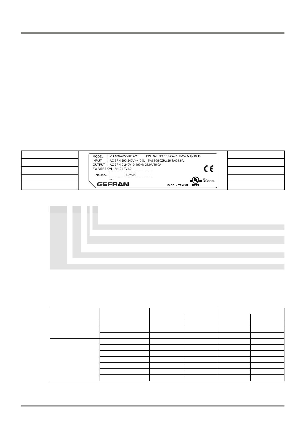
2.1. Nameplate Data
It is essential to verify the VDI100 inverter nameplate and make sure that the VDI100 inverter has the correct
rating so it can be used in your application with the proper sized AC motor.
Unpack the
(1) The
(2) The
VDI100 inverter and start-up and installation manual are contained in the package.
VDI100 inverter has not been damaged during transportation there should be no dents or parts miss-
ing.
(3) The
VDI100 inverter is the type you ordered. You can check the type and specications on the main name-
plate.
(4) Check that the input voltage range meets the input power requirements.
(5) Ensure that the motor
HD: Heavy Duty (Constant Torque); ND: Normal Duty (Variable Torque) (1HP = 0.746 kW)
Drive model ->
Input and output data ->
Serial number ->
ModelIdentication
VDI100-X XXX-KXX-X -Y
(1)
1ph / 3ph, VDI100-1007-KBX-2T ... VDI100-2022-KBX-2T only.
2.2. InverterModels–MotorPowerRating(HD–HeavyDuty)
VDI100 inverter and check the following:
kW (HP) matches the motor rating of the inverter.
EMC Filter: F = included; [Empty] = not included
Rated voltage: 2T = 230 Vac,
Software: X = standard
Braking unit:
Keypad: K = Integrated (LED keypad with 5-digits 7-segment
Drive power, in kW
Mechanical drive sizes
VDI100 drive series
<- Power rating
<- Approvals
(1)
3ph; 4 = 400 Vac , 3ph
/
(1ph)
B = included; X = not included
display)
230V Class
Voltage VDI100 Model Applied Motor Filter
(HP) (kW) with without
1ph / 3ph,
200~240V +10%/-15%,
50/60Hz
3ph, 200~240V
+10%/-15%
50/60Hz
VDI100-1007-KBX-2T 1 0.75 •
VDI100-1015-KBX-2T 2 1.5 •
VDI100-2022-KBX-2T 3 2.2 •
VDI100-2037-KBX-2T 5 3.7
VDI100-2055-KBX-2T 7.5 5.5 •
VDI100-3075-KBX-2T 10 7.5 •
VDI100-4110-KBX-2T 15 11 •
VDI100-4150-KBX-2T 20 15 •
VDI100-4185-KBX-2T 25 18.5 •
VDI100-5220-KXX-2T 30 22 •
•
Short Circuit Rating: 230V Class: 5kA
VDI100 • Instruction manual 11
Page 12
400V Class
Voltage VDI100 Model Applied Motor Filter
3ph, 380~480V
+10%/-15%
50/60Hz
Voltage VDI100 Model Applied Motor Filter
3ph, 380~480V
+10%/-15%
50/60Hz
(HP) (kW) with without
VDI100-1007 1 0.75 •
VDI100-1015 2 1.5 •
VDI100-1022 3 2.2 •
VDI100-2037 5 3.7 •
VDI100-2055 7.5 5.5 •
VDI100-3075 10 7.5 •
VDI100-3110 15 11 •
VDI100-4150 20 15 •
VDI100-4185 25 18.5 •
VDI100-4220 30 22 •
VDI100-5300 40 30 •
VDI100-5370-KXX-4-F 50 37 •
VDI100-5450-KXX-4-F 60 45 •
(HP) (kW) with without
VDI100-1007-KBX-4 1 0.75 •
VDI100-1015-KBX-4 2 1.5 •
VDI100-1022-KBX-4 3 2.2 •
VDI100-2037-KBX-4 5 3.7 •
VDI100-2055-KBX-4 7.5 5.5 •
VDI100-3075-KBX-4 10 7.5 •
VDI100-3110-KBX-4 15 11 •
VDI100-3150-KBX-4 20 15 •
VDI100-4185-KBX-4 25 18.5 •
VDI100-4220-KBX-4 30 22 •
VDI100-5300-KBX-4 40 30 •
VDI100-5370-KXX-4 50 37 •
VDI100-5450-KXX-4 60 45 •
VDI100-5550-KXX-4 75 55 •
VDI100-6750-KXX-4 100 75 •
VDI100-6900-KXX-4 125 94 •
VDI100-71100-KXX-4 150 112 •
VDI100-71320-KXX-4 175 130 •
VDI100-71600-KXX-4 215 160 •
Short Circuit Rating: 400V Class: 5kA
12 VDI100 • Instruction manual
Page 13
3. Environment and Installation
Important
3.1. Environment
The environment will directly affect the proper operation and the life span of the inverter. To ensure that the
inverter will give maximum service life, please comply with the following environmental conditions:
Protection Class IP20/NEMA 1 or IP00
Operating Temperature Ambient Temperature: (-10°C - +40°C (14 -104 °F)
Without Cover: -10°C - +50°C (14-122 °F); but it is required to derate 2% of current at each additional 1°C.
The maximum operating temperature is 60°C.
If several inverters are placed in the same control panel, provide a heat removal means to maintain ambient
temperatures below 40°C
Storage Temperature -20°C - +70°C (-4 -158 °F)
Humidity 95% non-condensing
Relative humidity 5% to 95%, free of moisture.
(Follow IEC60068-2-78 standard)
Altitude Altitude: Below 1000 m (3281 ft.)
It is required to derate 1% of current at each additional 100 m.
The maximum altitude is 3000 m.
Installation Site Avoid exposure to rain or moisture.
Avoid direct sunlight.
Avoid oil mist and salinity.
Avoid corrosive liquid and gas.
Avoid dust, lint fibers, and small metal filings.
Keep away from radioactive and flammable materials.
Avoid electromagnetic interference (soldering machines, power machines).
Avoid vibration (stamping, punching machines etc.).
Add a vibration-proof pad if the situation cannot be avoided.
Shock Maximum acceleration: 1.0G (9.8m/s²), from 49.84 to 150 Hz
Displacement amplitude : 0.3mm (peak value), from 10 to 49.84 Hz (Follow IEC60068-2-6 standard)
Protection
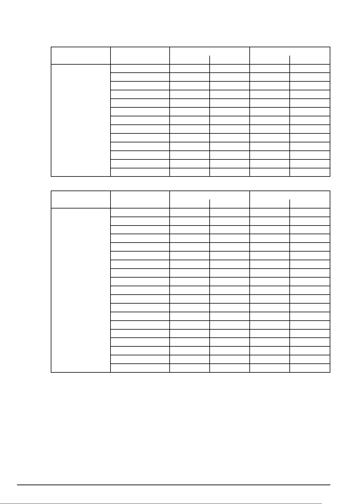
3.2. Installation
When installing the inverter, ensure that inverter is installed in upright position (vertical direction) and there is
adequate space around the unit to allow normal heat dissipation as per the following Fig. 3.2.1
5.9in.
150mm
X
5.9in.
150mm
Fig3.2.1:VDI100Installationspace
X=1.18”(30mm)forinverterratingsupto
X=1.96”(50mm)forinverterratings
18.5 kW (25HP)
22 kW(30HP)orhigher
Ambient
temperature
-10 to +40°C
X
5.9in.
150mm
5.9in.
150mm
Air Flow
The inverter heatsink temperature can reach up to 194°F / 90°C during operation; make sure to use insulation mate-
VDI100 • Instruction manual 13
Page 14
rial rated for this temperature.
Latempératuredudissipateurdechaleurdel’inverseurpeutatteindre194°F/90°Cpendantle
fonctionnement;veilleràutiliserunmatériauisolantcompatibleaveccettetempérature.
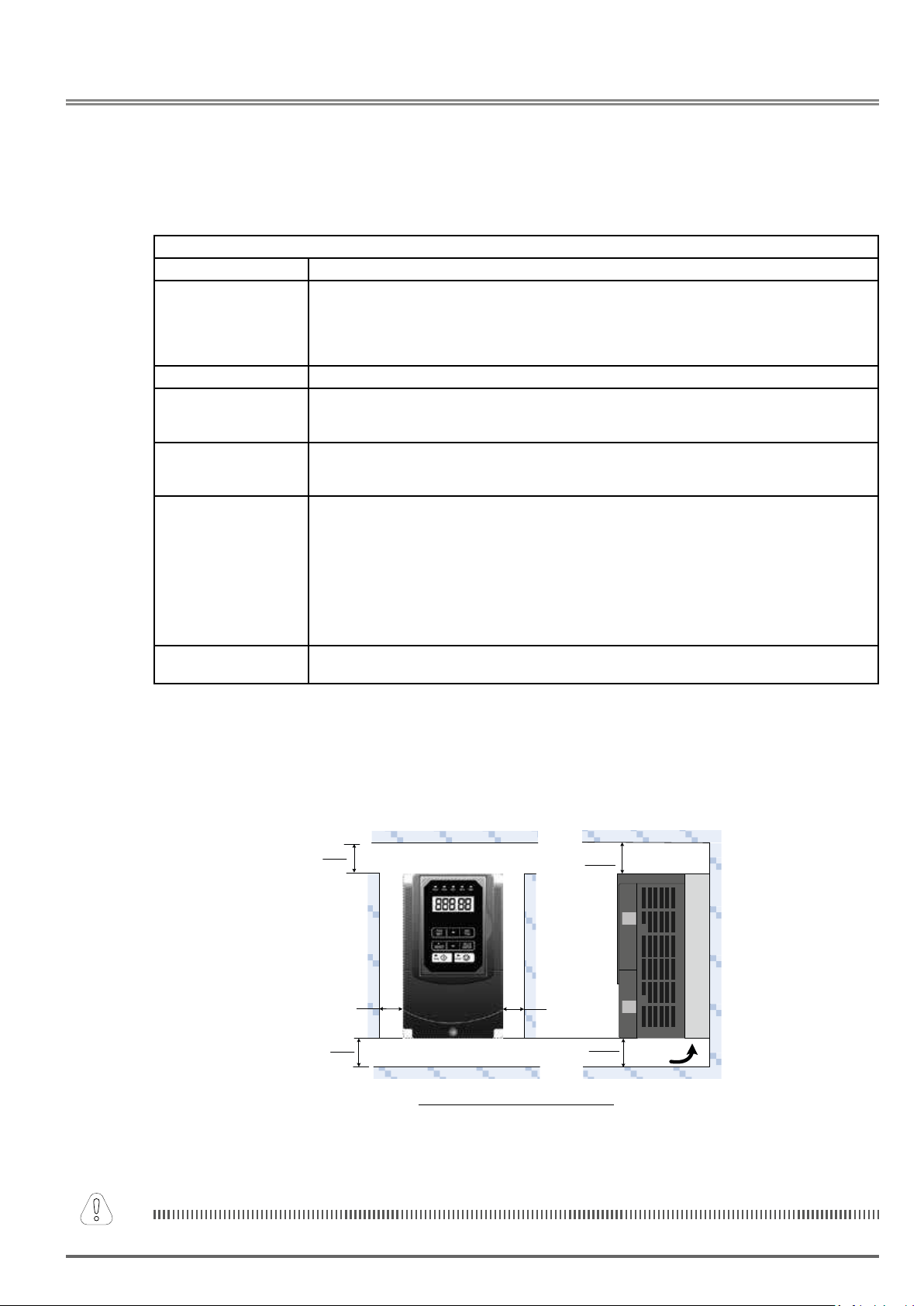
3.3. External View
(a)Sizes1and2(230VClass:0.75~5.5kW/400VClass:0.75~5.5kW)
Fan cover
Mounting hole
Heatsink
Front cover
Keypad
Terminal
cover
(Wall-mounted type, IEC IP20) (Wall-mounted type, IEC IP20, NEMA1)
(b)
Sizes3and4(230VClass:7.5~18.5kW/400VClass:7.5~22kW)
Front cover
Nameplate
and barcode
Mounting hole
Anti-dust cover
Front cover
Keypad
Terminal
cover
Anti-dust cover
Front cover
Fan cover
Mounting hole
Rings (4 rings)
Nameplate
and barcode
Mounting hole
Keypad
Terminal
cover
Keypad
Nameplate
and barcode
Terminal
cover
(Wall-mounted type, IEC IP20) (Wall-mounted type, IEC IP20, NEMA1)
Nameplate
and barcode
14 VDI100 • Instruction manual
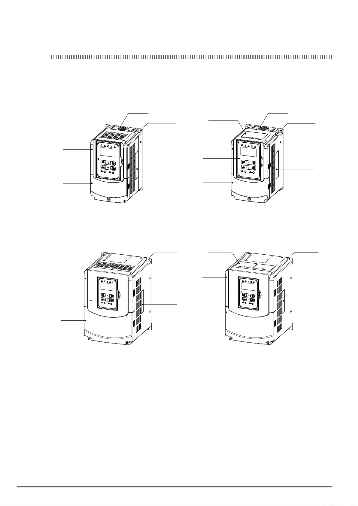
Page 15
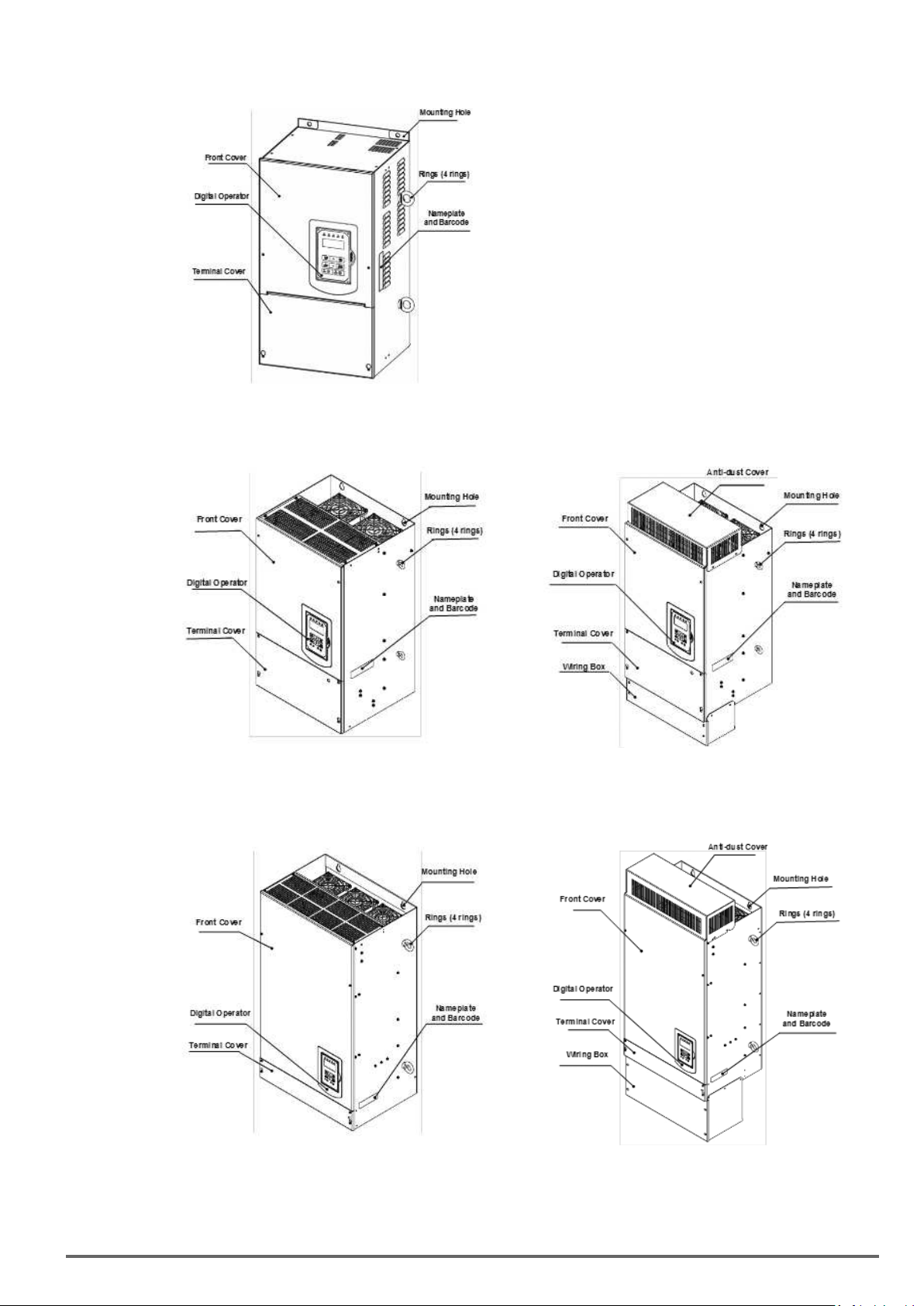
(c)Size5(230VClass:22kW/400VClass:30~55kW)
(Wall-mounted type, IEC IP20, NEMA1)
Size6(400VClass:75~90kWandmodelswith“NEMA1kitforVDI100”)
(d)
(Wall-mounted type, IEC IP20) (Wall-mounted type, IEC IP20, NEMA1)
Size7(400VClass:110~160kWandmodelswith“NEMA1kitforVDI100”)
(e)
(Wall-mounted type, IEC IP00) (Wall-mounted type, IEC IP20, NEMA1)
VDI100 • Instruction manual 15
Page 16
3.4. Warning Labels
Important
Warning information located on the front cover must be read upon installation of the inverter.
Lorsdel’installationdel’inverseur,lirelesavertissementsapposéssurlecachedefaçade.
(a) Drive sizes 1, 2 and 3
WARNING / AVERTISSEMENT
Risk of electrical shock. Shut off main power and wait for 5 minutes before servicing.
Risque de choc électrique. Couper l’alimentation principale et attendre 5 minutes avant l’entretien.
Hot surface. Risk of burn.
Surface chaude. Risque de brûlure.
See manual before operation.
Consultez le manuel avant l’operation.
(b) Drive sizes 4, 5, 6 and 7
WARNING / AVERTISSEMENT
Risk of electrical shock. Shut off main power and wait for 15 minutes before servicing.
Risque de choc électrique. Couper l’alimentation principale et attendre 15 minutes avant l’entretien.
CAUTION / ATTENTION
See manual before operation.
Consultez le manuel avant l’operation.
Caution
3.5. Removing the Front Cover and Keypad
• Before making any wiring connections to the inverter the front cover needs to be removed.
• It is not required to remove the digital operator before making any wiring connections.
• Models
230V Class 2.2 ~ 18.5 kW and 400V Class 0.75 ~ 22 kW have a plastic cover. Loosen the screws
and remove the cover to gain access to the terminals and make wiring connections. Place the plastic cover
back and fasten screws when wiring connections have been made.
• Models
230V Class 22 kW and 400V Class 30 ~ 160 kW have a metal cover. Loosen the screws and
remove the cover to gain access to the terminals and make wiring connections. Place the metal cover back
and fasten screws when wiring connections have been made.
• Avant de procéder aux branchements des câblages sur l’inverseur, il est nécessaire de retirer le cache de
façade.
• En revanche, il n’est pas nécessaire de retirer l’opérateur numérique avant les branchements des câblages.
• Les modèles 230V Classe 2.2 ~ 18,5 kW et 400V Classe 0,75 ~ 22 kW sont pourvus d’un cache en plastique. Desserrer les vis et retirer le cache pour pouvoir accéder aux terminaux et réaliser les branchements
des câblages. Ensuite, reposer le cache en plastique et serrer ses vis de xation.
• Les modèles 230V Classe 22 kW et 400V Classe 30 ~ 160 kW sont pourvus d’un cache en métal. Desserrer les vis et retirer le cache pour pouvoir accéder aux terminaux et réaliser les branchements des câblag-
es. Ensuite, reposer le cache en métal et serrer ses vis de xation.
16 VDI100 • Instruction manual
Page 17
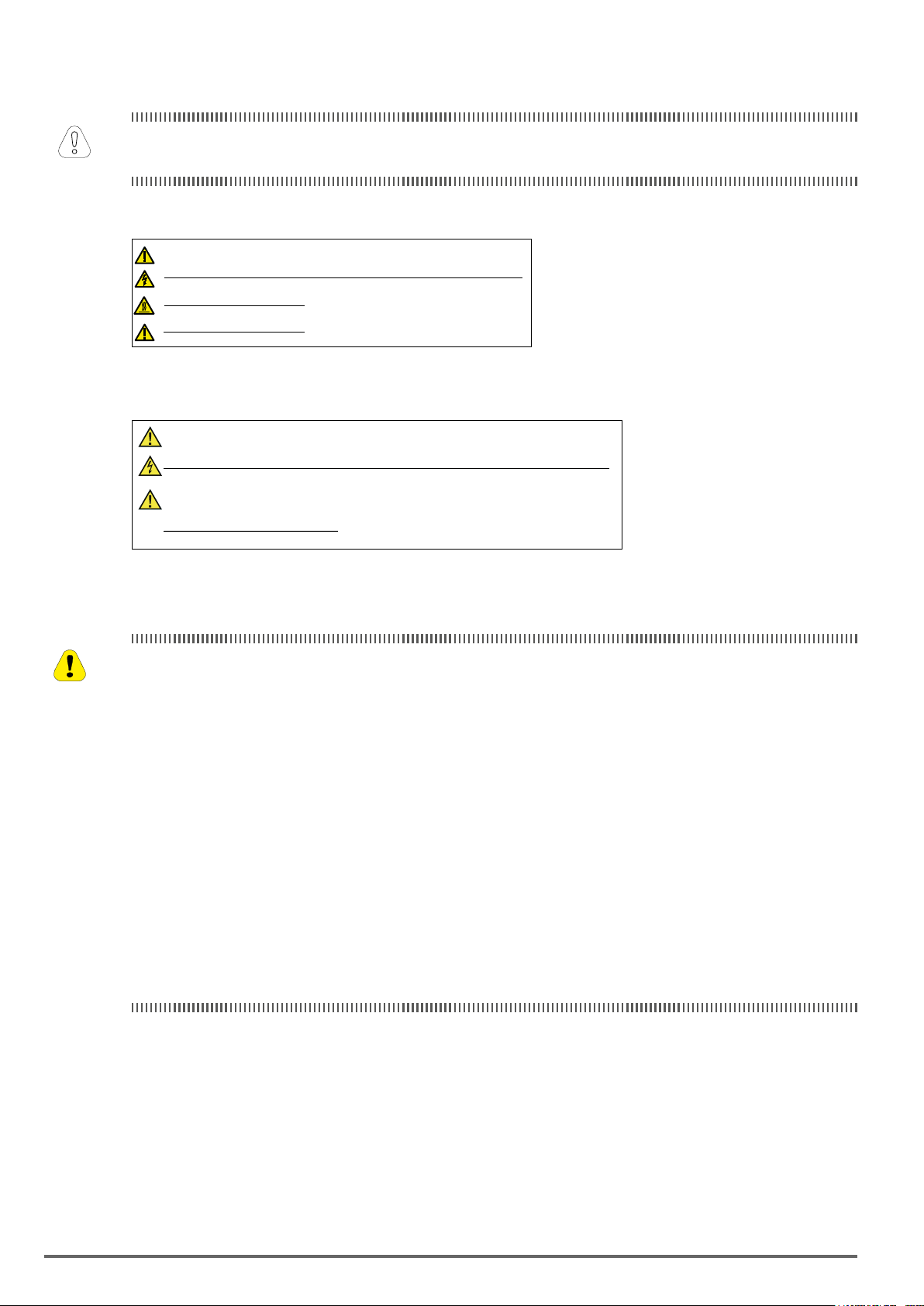
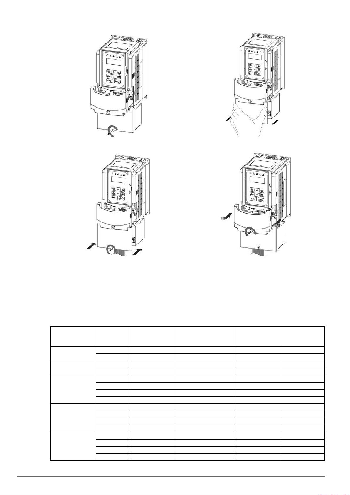
3.5.1. Standard Type
(a)Sizes1and2(230VClass:0.75~5.5kW/400VClass:0.75~5.5kW)
Step 1: Unscrew Step 2: Remove cover
Step 3: Make wire connections and place cover back Step 4: Fasten screw
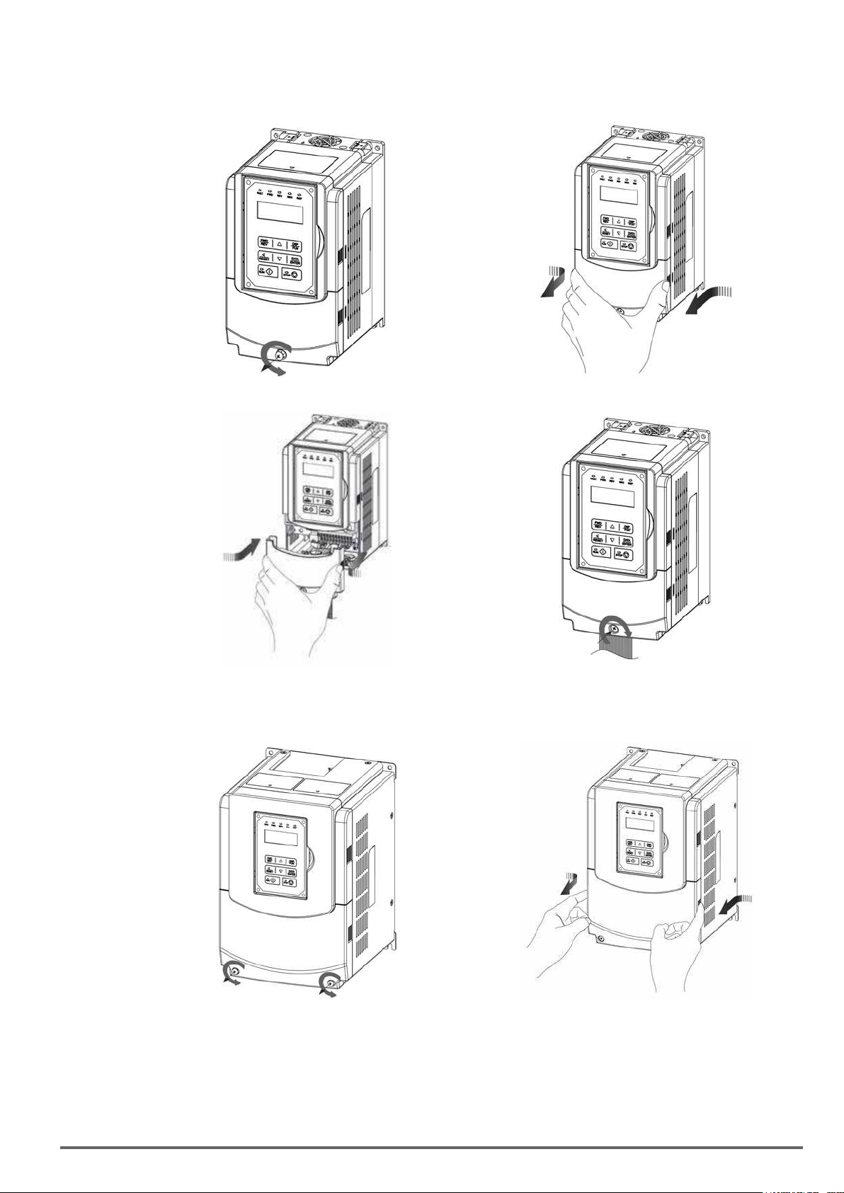
(b)
Sizes3and4(230VClass:7.5~18.5kW/400VClass:7.5~22kW)
Step 1: Unscrew cover Step 2: Remove cover
VDI100 • Instruction manual 17
Page 18
Step 3: Make wire connections and place cover back Step 4: Fasten screw
(c)
Size5(230VClass:22kW/400VClass:30~55kW)
Step 1: Unscrew cover Step 2: Remove cover
Step 3: Make wire connections and place cover back Step 4: Fasten screw
18 VDI100 • Instruction manual
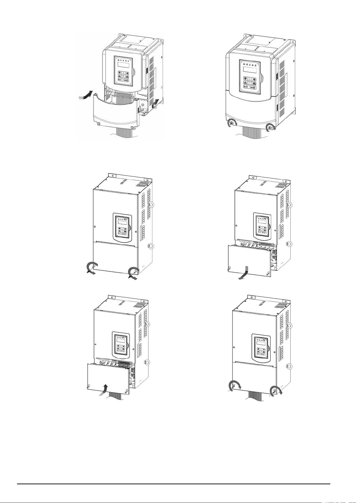
Page 19
(d)Sizes6and7(400VClass:75~160kW)
Step 1: Unscrew cover Step 2: Remove cover
Step 3: Make wire connections and place cover back Step 4: Fasten screw
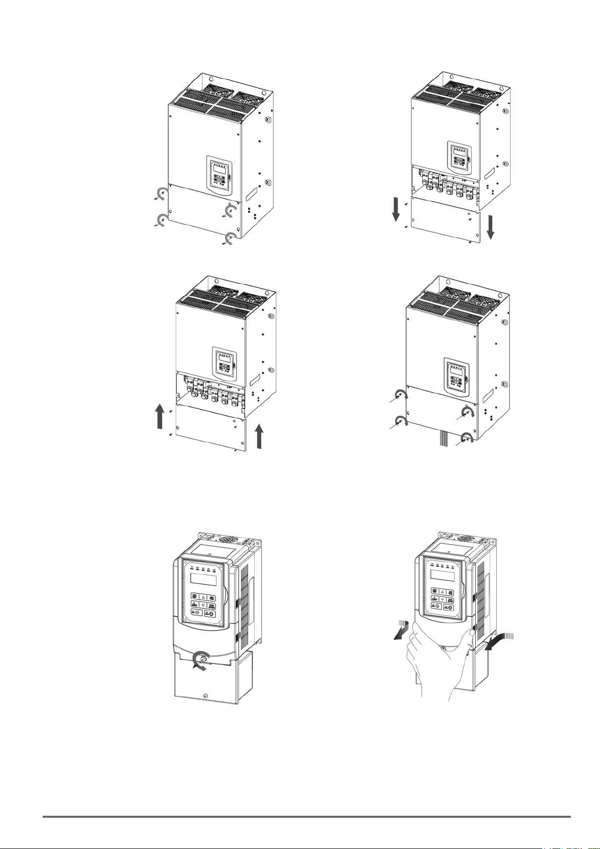
3.5.2. Add-on lter type (400V Class: 0.75 ~ 45 kW)
Step 1: Unscrew cover Step 2: Remove cover
VDI100 • Instruction manual 19
Page 20
Step 3: Unscrew filter section Step 4: Remove filter cover
Step 5: Make connections and place filter cover back Step 6: Fasten screw
3.6. Wire Gauges and Tightening Torque
To comply with UL standards, use UL approved copper wires (rated 75° C) and round crimp terminals (UL Listed products) as shown in table below when connecting to the main circuit terminals. Gefran recommends using
crimp terminals manufactured by NICHIFU Terminal Industry Co., Ltd and the terminal crimping tool recommended by the manufacturer for crimping terminals and the insulating sleeve.
Wire size
2
(AWG) kgf.cm (in.lbs)
mm
0.75 (18)
1.25 (16)
2 (14)
3.5 / 5.5 (12/10)
8 (8)
Terminal
screw size
M3.5 R1.25-3.5 8.2 to 10 (7.1 to 8.7) TIC 1.25 NH 1
M4 R1.25-4 12.2 to 14 (10.4 to 12.1) TIC 1.25 NH 1
M3.5 R1.25-3.5 8.2 to 10 (7.1 to 8.7) TIC 1.25 NH 1
M4 R1.25-4 12.2 to 14 (10.4 to 12.1) TIC 1.25 NH 1
M3.5 R2-3.5 8.2 to 10 (7.1 to 8.7) TIC 2 NH 1 / 9
M4 R2-4 12.2 to 14 (10.4 to 12.1) TIC 2 NH 1 / 9
M5 R2-5 22.1 to 24 (17.7 to 20.8) TIC 2 NH 1 / 9
M6 R2-6 25.5 to 30.0 (22.1 to 26.0) TIC 2 NH 1 / 9
M4 R5.5-4 12.2 to 14 (10.4 to 12.1) TIC 5.5 NH 1 / 9
M5 R5.5-5 20.4 to 24 (17.7 to 20.8) TIC 5.5 NH 1 / 9
M6 R5.5-6 25.5 to 30.0 (22.1 to 26.0) TIC 5.5 NH 1 / 9
M8 R5.5-8 61.2 to 66.0 (53.0 to 57.2) TIC 5.5 NH 1 / 9
M4 R8-4 12.2 to 14 (10.4 to 12.1) TIC 8 NOP 60
M5 R8-5 20.4 to 24 (17.7 to 20.8) TIC 8 NOP 60
M6 R8-6 25.5 to 30.0 (22.1 to 26.0) TIC 8 NOP 60
M8 R8-8 61.2 to 66.0 (53.0 to 57.2) TIC 8 NOP 60
Model of the round
crimp terminal
Fastening torque
Model of insulating
sleeve
Model of
crimp tool
20 VDI100 • Instruction manual
Page 21
Wire size
2
(AWG) kgf.cm (in.lbs)
mm
14 (6)
22 (4)
30 / 38 (3 /2)
50 / 60 (1/1/0)
70 (2/0)
80 (3/0)
100 (4/0)
Terminal
screw size
M4 R14-4 12.2 to 14 (10.4 to 12.1) TIC 14 NH 1 / 9
M5 R14-5 20.4 to 24 (17.7 to 20.8) TIC 14 NH 1 / 9
M6 R14-6 25.5 to 30.0 (22.1 to 26.0) TIC 14 NH 1 / 9
M8 R14-8 61.2 to 66.0 (53.0 to 57.2) TIC 14 NH 1 / 9
M6 R22-6 25.5 to 30.0 (22.1 to 26.0) TIC 22 NOP 60/ 150H
M8 R22-8 61.2 to 66.0 (53.0 to 57.2) TIC 22 NOP 60/ 150H
M6 R38-6 25.5 to 30.0 (22.1 to 26.0) TIC 38 NOP 60/ 150H
M8 R38-8 61.2 to 66.0 (53.0 to 57.2) TIC 38 NOP 60/ 150H
M8 R60-8 61.2 to 66.0 (53.0 to 57.2) TIC 60 NOP 60/ 150H
M10 R60-10 102 to 120 (88.5 to 104) TIC 60 NOP 150H
M8 R70-8 61.2 to 66.0 (53.0 to 57.2) TIC 60 NOP 150H
M10 R70-10 102 to 120 (88.5 to 104) TIC 60 NOP 150H
M10 R80-10 102 to 120 (88.5 to 104) TIC 80 NOP 150H
M16 R80-16 255 to 280 (221 to 243) TIC 80 NOP 150H
M10 R100-10 102 to 120 (88.5 to 104) TIC 100 NOP 150H
M12 R100-12 143 to 157 (124 to 136) TIC 100 NOP 150H
M16 R80-16 255 to 280 (221 to 243) TIC 80 NOP 150H
Model of the round
crimp terminal
3.7. Wiring Peripheral Power Devices
Fastening torque
Model of insulating
sleeve
Model of
crimp tool
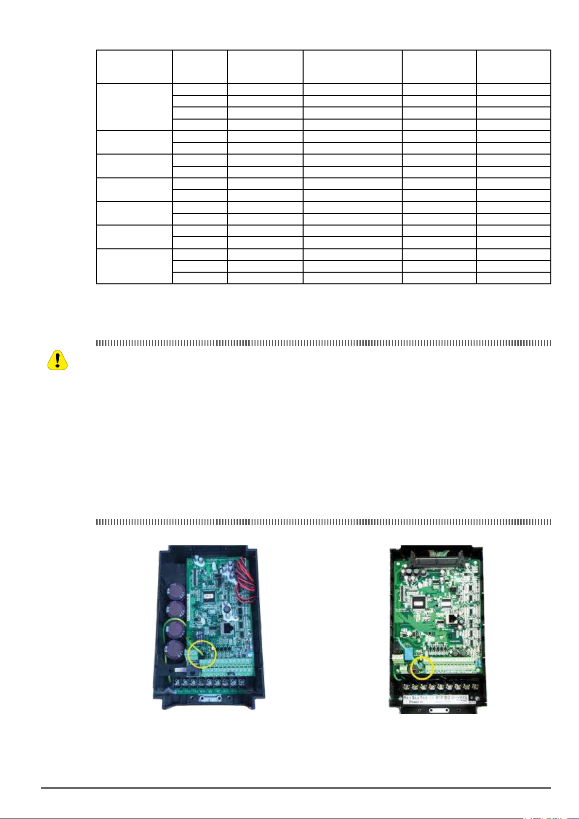
Caution
• After power is shut off to the inverter the capacitors will slowly discharge. Do NOT touch the inverter circuit
or replace any components until the “CHARGE” indicator is off.
• Do NOT wire or connect/disconnect internal connectors of the inverter when the inverter is powered up or
after power off but the “CHARGE”” indicator is on.
• Do NOT connect inverter output U, V and W to the AC power source. This will result in damage to the
inverter.
• The inverter must be properly grounded. Use terminal E to connect earth ground and comply with local
standards.
• It is required to disconnect the ground wire in the control board if the inverter is not grounded.
• Do NOT perform a dielectric voltage withstand test (Megger) on the inverter this will result in inverter damage to the semiconductor components.
• Do NOT touch any of the components on the inverter control board to prevent damage to the inverter by
static electricity.
230V Class : 0.75~1.5 kW / 400V Class: 0.75~2.2 kW 230V Class : 2.2~5.5 kW / 400V Class: 3.7~5.5 kW
Disconnect the ground wire of J1. on the control board (C/B). Disconnect the ground wire of J1. on the control board (C/B).
VDI100 • Instruction manual 21
Page 22
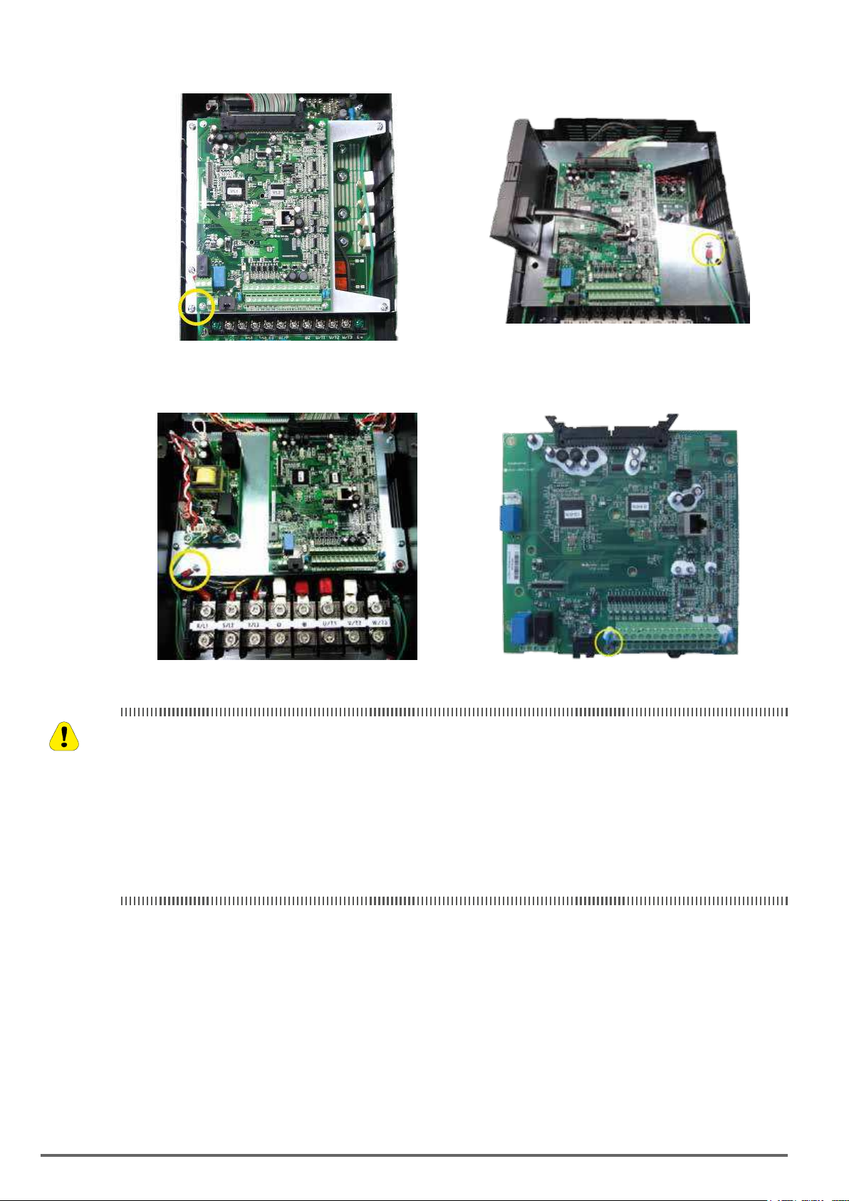
230V Class : 7.5kW / 400V Class: 7.5~15 kW 230V Class : 11~18.5 kW / 400V Class: 18.5~22kW
Disconnect the ground wire of isolated metal plate. Disconnect the ground wire of isolated metal plate.
230V Class : 22kW / 400V Class: 30~55 kW 400V Class: 75 kW and the above
Caution
Disconnect the ground wire of isolated metal plate. Disconnect the ground screw below the C/B and ground studs of
isolated metal plate.
• Refer to the recommended wire size table for the appropriate wire to use. The voltage between the power
supply and the input terminals of the inverter may not exceed 2%.
Phase-to-phasevoltagedrop(V)=√3×resistanceofwire(Ω/km)×lengthoflinem)×current×10
-3
.
(km=3280xfeet)/(m=3.28xfeet)
• Reduce the carrier frequency (parameter 11-01) If the cable from the inverter to the motor is over 25m
(82ft). A high-frequency current can be generated by stray capacitance between the cables and result in an
overcurrent trip of the inverter, an increase in leakage current, or an inaccurate current readout.
• To protect peripheral equipment, install fast acting fuses on the input side of the inverter. Refer to section
11.4 for additional information.
22 VDI100 • Instruction manual
Page 23
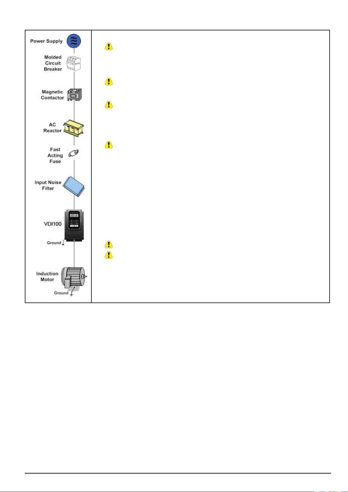
Power supply:
Caution
Caution
Caution
Caution
Caution
Caution
•
Make sure the correct voltage is applied to avoid damaging the inverter.
Molded-case circuit breaker (MCCB) or fused disconnect:
• A molded-case circuit breaker or fused disconnect must be installed between the AC source and the inverter that
conforms to the rated voltage and current of the inverter to control the power and protect the inverter.
•
Do not use the circuit breaker as the run/stop switch for the inverter.
Ground fault detector / breaker:
•
Install a ground fault breaker to prevent problems caused by current leakage and to protect personnel. Select
current range up to 200mA, and action time up to 0.1 second to prevent high frequency failure.
Magnetic contactor:
• Normal operations do not need a magnetic contactor. When performing functions such as external control and auto
restart after power failure, or when using a brake controller, install a magnetic contactor.
•
Do not use the magnetic contactor as the run/stop switch for the inverter.
AC line reactor for power quality:
• When inverters are supplied by a high capacity power source (> 600kVA), an AC reactor can be connected to improve
the power factor.
Install Fast Acting Fuse:
• To protect peripheral equipment, install fast acting fuses in accordance with the specifications in section
11.4.
Input Noise filter:
• A filter must be installed when there are inductive loads affecting the inverter. The inverter meets EN 61800-3:2012,
category C3 or C2 when the Gefran special filter is used. See section 11.3.
Inverter:
• Output terminals T1, T2, and T3 are connected to U, V, and W terminals of the motor. If the motor runs in reverse while
the inverter is set to run forward, swap any two terminals connections for T1, T2, and T3.
•
•
To avoid damaging the inverter, do not connect the output terminals T1, T2, and T3 to AC input power.
Connect the ground terminal properly. (230V class: Rg <100W; 400V class: Rg <10W.)
Motor:
• If the inverter drives multiple motors the output rated current of the inverter must be greater than the total current of all
the motors.
VDI100 • Instruction manual 23
Page 24
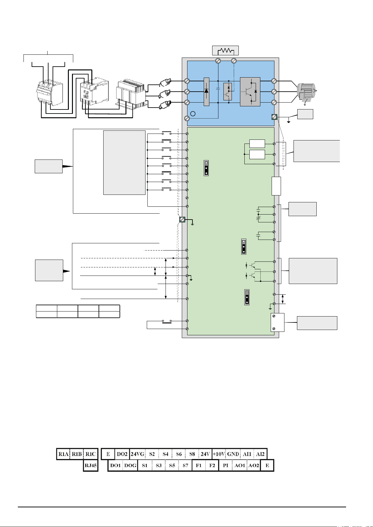
3.8. General Wiring Diagram
Vcc 24V 12V 5V
R 2KΩ 750Ω 100Ω
AC Input Voltage
L1(R)
L2(S)
MCCB
L3(T)
Magnetic
Contactor
AC
Reactor
Fast Acting
Fuses
L1/R
L2/S
L3/T
-
B1/P
+
-
Braking Resistor
B2 *1
U/T1
V/T2
W/T3
3ph Induction motor
E
Ground
< 100Ω
Main Power Section
FWD / STOP
REV / STOP
Multi-Step Speed Ref. 1
Digital Input
Section
Multi-
Functional
Digital Inputs
Multi-Step Speed Ref. 2
Multi-Step Speed Ref. 3
Fault Reset
Jog Command
External base block
Factory Default
-10V ~ 0 ~ 10V, 20KΩ
External
Analog
Inputs
4 ~ 20mA / 0 ~ 10V, 250KΩ
0V
Pulse Input
P
P
P
S1
S2
S3
S4
S5
S6
S7
S8
24V Power terminal for digital signal (source)
24VG Digital signal common (sink)
+10V: Power for Analog Input
(max. 20mA)
AI1: Multi-Function Analog Input
(-10~10V/0~10V, 20KΩ)
AI2: Multi-Function Analog Input
(0~10V/4~20mA, 250KΩ)
GND: Analog Signal Common
-10V: Power for Analog Input
PI Pulse Input 32kHz Max.
*2
SW3
SOURCE PNP
SINK NPN (DEFAULT)
VDI100
*7
Analog
Output 1
Analog
Output 2
NO
NC
*3
SW2
V
I
*5
*10
SW4
CN3
(R1A)
(R1C)
(R1B)
*6
GND
AO1
AO2
GND
R2A
R2C
DO1
DO2
DOG
PO
Analog Outputs
AO1 : 0 – 10 VDC
AO2 : 0 – 10 VDC / 4-20mA
Note 1
Option Card (PG)
Multi-Function
Relay Output
Contact rating:
250 VAC < 1.0A
30 VDC < 1.0A
*5
Multi-Functional transistor
digital outputs
Open Collector, 48V
@50mA
(opto-isolated)
*5
Multi-function pulse
P
output 32kHz Max.
1:
F1
Run Permissive Input
F2
*1: Models 230V class 0.75 ~ 18.5kW and 400V class 0.75 ~ 30kW or lower ratings have a built-in braking transistor. To use this braking transistor a braking resistor can be
connected between B1 and B2.
CN6 (RJ45)
*4
S(+)
2:
S(-)
RS485
Communication Port
*2: Use SW3 to select between Sink (NPN, with 24VG common) or Source (PNP, with +24V common) for multi-function digital input terminals S1~S8.
*3: Use SW2 to switch between voltage (0~10V/-10~10V) and current (4~20mA) input for Multi-function analog input 2 (AI2).
*4: Run Permissive input F1 and F2 is a normally closed input. This input should be closed to enable the inverter output. To activate this input remove the jumper wire between
F1 and F2.
*5: Models 230V Class 2.2kW and 400V Class 3.7kW and higher ratings include terminals -10V, S(+), S(-),R2A-R2C and PO- GND.
*6. 230V Class 1.5kW and 400V Class 2.2kW and lower ratings include terminal DO2.
*7: When using the open collector for pulse input, it doesn’t need resistance because of built-in pull-up resistance.
*8: AO2 default setting is 0~+10V.
*9: 400V class 75kW~160kW have built-in DC reactors.
*10: It need turn on the switch for the terminal resistor RS485 in the last inverter when many inverters in parallel connection. Please refer to Appendix A
3.9. UserTerminals(ControlCircuitTerminals)
230V Class: 0.75 ~ 1.5 kW, 400V Class: 0.75 ~ 2.2kW
24 VDI100 • Instruction manual
Page 25
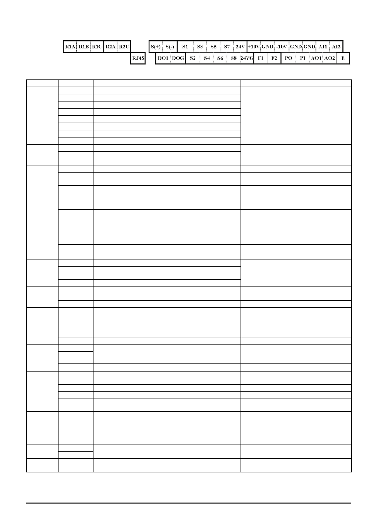
230V Class: 2.2~22kW, 400V Class: 3.7~160kW,
Description of User Terminals
Type Terminal Terminal Function Signal Level / Information
S1 2-wire forward/ stop (default) * 1
S2 2-wire reversal/ stop (default) * 1
S3 Multi-speed/ position setting command 1 (default) * 1
Digital input
signal
S4 Multi-speed/ position setting command 2 (default) * 1
S5 Multi-speed/ position setting command 3 (default) * 1
S6 Fault reset (default) * 1
S7 JOG frequency command (default) * 1
S8 External B.B.(Base Block) stop (coast to stop) (default) * 1
24V Power
supply
24V Digital signal SOURCE point (SW3 switched to SOURCE )
24VG
Common terminal of Digital signals
Common point of digital signal SINK ( SW3 switched to SINK )
+10V Power for external speed potentiometer +10V (Max. current , 20mA)
-10V
AI1
Only above
terminal function
Multi-function analog input for speed reference (0-10V input)/
(-10V~10V input)
230V Class 2.2kW/ 400V Class 3.7kW (include) support this
Analog input
signal
AI2
Multi-function analog input terminals *2, can use SW2 to switch voltage
or current input (0~10V)/(4-20mA)
GND Analog signal ground terminal ----
E Shielding wire’s connecting terminal (Ground) ----
AO1 Multi-function analog output terminals *2 (0~10V output)
Analog output
signal
AO2
Multi-function analog output terminals *2. can use SW6 to switch
voltage or current input (0~10V / 4-20mA output)
GND Analog signals ground terminal
Pulse output
signal
Pulse input
signal
PO
Pulse output, Band width 32KHz, only above
Class 3.7kW (include) support this terminal function.
GND Analog signals ground terminal ----
PI
Pulse command input,
Bandwidth: 32KHz
230V Class 2.2kW/ 400V
GND Analog signals ground terminal ----
DO1
Digital output
DO2
Size one only)
(
Multi-function(open collector transistor) output *1
DOG Open collector transistor digital ground
Relay A contact (multi-function output terminal)
Relay B contact (multi-function output terminal)
With the same functions as DO1/DO2
Relay output
R1A
R1B Relay contact common terminal,
R1C With the same functions as DO1/DO2
R2A-R2C
(Size 2 and above)
F1 On: normal operation.
Run Permis-
sive Input
F2 24V Ground
Off: stop. (Jumper wired between F1 and F2 has to be removed by
using external contact to stop.)
Activation of this input will switch off the inverter output causing the
motor to coast to stop.
RS-485 port
Grounding E (G)
Notes:
*1:Multi-function digital input/ output can be referred to in this manual (Group 03: External Terminals Digital Input / Output Function Group).
*2:Multi-function analog input/ output can be referred to in this manual (Group 04 - External Terminal Analog Signal Input (Output) Function Group).
S (+)
S (-)
RS485/ Modbus communication protocol Differential input and output
Grounding to earth
Shield the connecting terminal
Signal Level 24 VDC
(photo isolated)
Maximum current: 8mA
Maximum voltage: 30 Vdc
Input impedance: 4.22kΩ
±15%,
Max. output current: 250mA
(The sum of all loads connected )
-10V (Max. current , 20mA)
From 0 to +10V,
From -10V to +10V
Input impedance : 20KΩ
Resolution: 11bit + 1
From 0 to +10V,
From -10V to +10V
Input impedance: 200KΩ
From 4 to 20 mA
Input impedance: 250KΩ
Resolution: 11bit + 1
From 0 to 10V, From 4 to 20mA
(Load < 500Ω)
PWM Frequency: 10KHz
Max. Frequency: 32KHz
Open Collector output
L: from 0.0 to 0.5V
H: from 4.0 to 13.2V
Max. Frequency: 0 - 32KHz
Built-in pull-up resistance. When open collector input
is used, it is not required to connect resistance.
48Vdc, 2~50mA
Open-collector output
Rating: 250Vac, 10 mA ~ 1A
30Vdc, 10 mA ~ 1A
Rating: 250Vac, 10 mA ~ 1A
30Vdc, 10 mA ~ 1A
24Vdc, 8mA, pull-up
----
VDI100 • Instruction manual 25
Page 26
Caution
• Maximum output current capacity for terminal 10V is 20mA.
• Multi-function analog output AO1 and AO2 are used for an analog output meter. Do not use these outputs
for feedback control.
• Control board’s 24V and ±10V are to be used for internal control only, Do not use the internal power-supply
to power external devices.
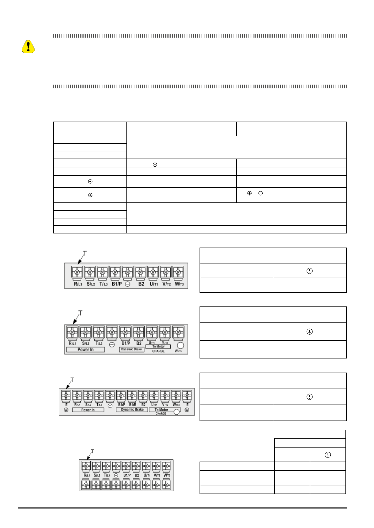
3.10. Power Terminals
Terminal
R/L1
S/L2
T/L3
B1/P
• B1/P-
230V Class: 0.75 ~ 18.5kW
400V Class: 0.75 ~ 30kW
Input Power Supply
(For single phase use terminals R/L1 and S/L2)
: DC power supply
B2 • B1/P-B2: external braking resistor
-
U/T1
Inverter outputV/T2
W/T3
E Ground terminal
230V Class: 0.75kW~1.5kW/ 400V Class: 0.75kW~2.2kW
230V Class: 2.2 ~ 22kW, 400V Class: 3.7 ~ 55kW
230V Class: 22kW
400V Class: 37 ~ 160kW
-
- : DC power supply or connect braking
·
module
Terminal screw size
T
M4 M4
T
M4 M4
230V Class: 7.5kW, 400V Class: 7.5 ~ 11kW
T
M6 M6
230V Class: 11~18.5kW, 400V Class: 15 ~ 30kW
400V Class: 15kW (Size 3)
230V Class: 11~18.5kW,
400V Class: 15 ~ 22kW
400V Class: 30kW
Terminal screw size
Terminal screw size
Terminal screw size
T
M6 M5
M6 M6
M6 M8
26 VDI100 • Instruction manual
Page 27
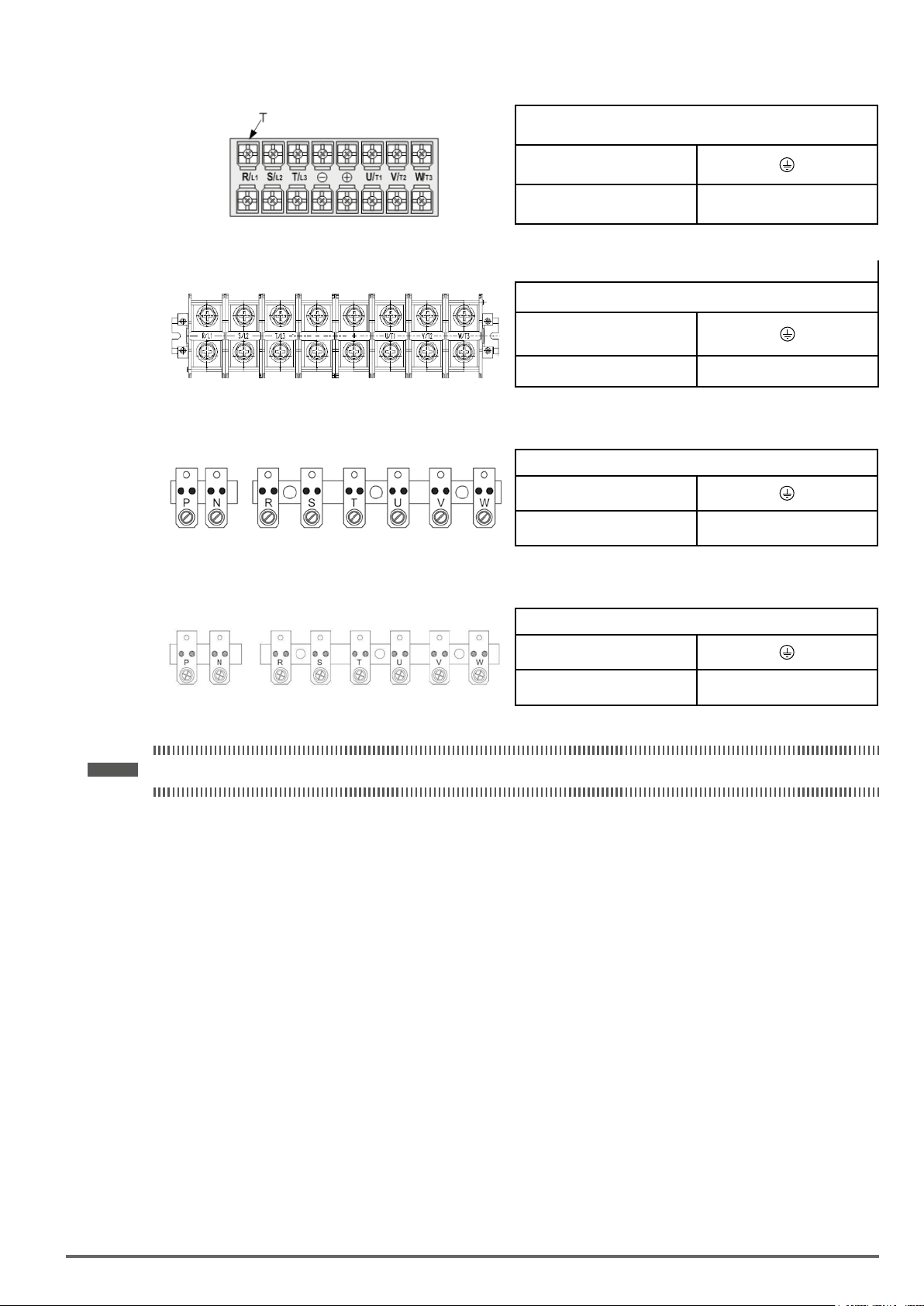
230V Class: 22kW, 400V Class: 37 ~ 55kW
T
M8 M8
400V Class: 75kW
T
M10 M10
400V Class: 90kW
T
M10 M10
Terminal screw size
Terminal
screw size
Terminal screw size
400V Class: 132~160kW
Note ! For wire gauges and screw torques, please refer to the table in section 3.6
Terminal screw size
T
M10 M10
VDI100 • Instruction manual 27
Page 28
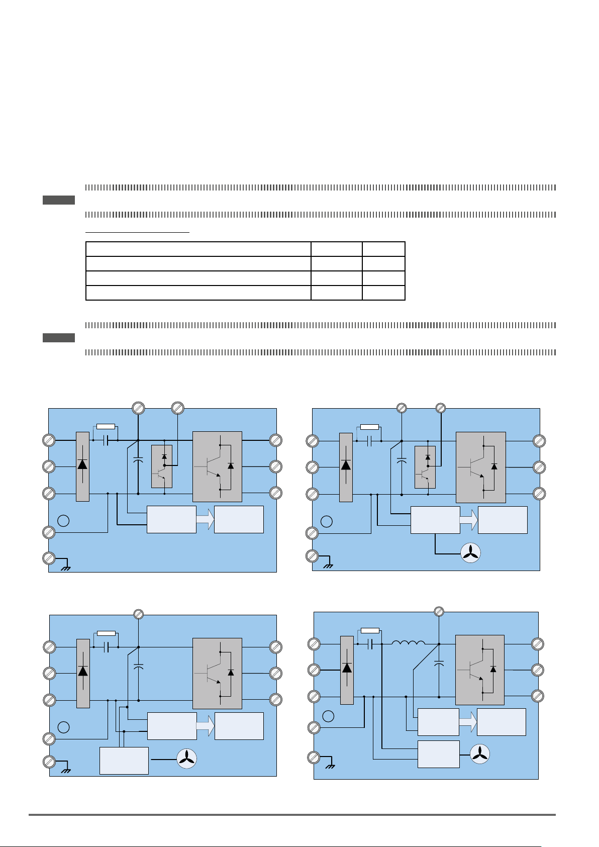
3.11. Input/OutputPowerSectionBlockDiagram
The following diagrams 1 - 5 show the basic conguration of the power sections for the range of power and
input voltages. This is shown for reference only and is not a detailed description.
DC power supply
All the VDI100 ranges below can be power supply from DC link:
- 230V 3ph up to 22kW,
- 400V 3ph up to 90kW
Note ! On VDI100 above 90kW, DC bus cannot be used.
DClinkconnectionterminals:
Range Terminals Diagrams
VDI100 230V 3ph up to 18.5kW and VDI100 400V 3ph up to 30kW B1/P and (-) 1 and 2
VDI100 230V 3ph 22kW and VDI100 400V 3ph 37-55kW (+) and (-) 3
VDI100 400V 3ph 75-90kW P and N 4
Note ! For DC power supply, fuses and DC pre-charge circuit must be provided externally.
1: 230V Class: 0.75 kW / 400V Class: 0.75 ~ 1.5 kW 2: 230V Class: 1.5 ~ 18.5 kW / 400V Class: 2.2 ~ 30 kW
DC /DC
Converter
B2
U/T1
V/T2
W/T3
Control
Circuit
Cooling Fan
L1/R
L2/S
L3/T
-
E
B1/P
+
-
Main Power Secon
DC /DC
Converter
B2
Control
Circuit
U/T1
V/T2
W/T3
L1/R
L2/S
L3/T
-
E
B1/P
+
-
Main Power Secon
3: 230V Class: 22 kW / 400V Class: 37 ~ 55 kW 4: 400V Class: 75 ~ 90 kW
+
L1/R
L2/S
L3/T
+
-
U/T1
V/T2
W/T3
L1/R
L2/S
L3/T
DC Link
Reactor
P
U/T1
+
-
V/T2
W/T3
-
E
DC /DC
DC /DC
Converter
Converter
Control
Circuit
Cooling Fan
Main Power Secon
N
E
DC /DC
Converter
DC /DC
Converter
Main Power Secon
Control
Circuit
Cooling Fan
28 VDI100 • Instruction manual
Page 29
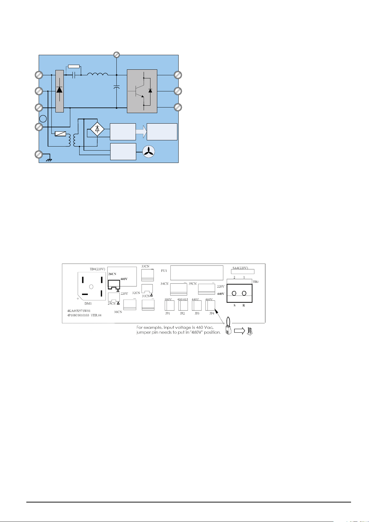
5: 400V Class: 110-132-160 kW
L1/R
L2/S
L3/T
N
P
+
-
DC /DC
Converter
AC/DC
U/T1
V/T2
W/T3
Control
Circuit
Cooling Fan
E
Main Power Secon
DC Link
Reactor
3.11.1. Cooling Fan Supply Voltage Selection (400V class)
The inverter input voltage range of the VDI100 400V class models ranges from 380 to 480Vac. In these models
the cooling fan is directly powered from the power supply. Inverter models VDI100-6900 ... 71600 requires the
user to select the correct jumper position based on the inverter input voltage (“440V” is the default position for
these models). Please select the correct position according to the input voltage. If the voltage setting is too
low, the cooling fan will not provide adequate cooling for the inverter resulting in an over-heat error. If the input
voltage is greater than 460Vac, select the “460V” position.
400V Class: 71100 ~ 71600kW
VDI100 • Instruction manual 29
Page 30
3.12. Inverter Wiring
Warning
Wiring Precautions
• Do NOT remove any protective covers or attempt any wiring while input power is applied. Connect all
wiring before applying input power. When making wiring changes after power up, remove input power
and wait a minimum of ve minutes after power has been turned off before starting. Also conrm that the
charge lamp is off and that DC voltage between terminals B1/P or (+) and (-) does not exceed 25V, otherwise electric shock may result.
• Only authorized personnel should work on the equipment. (Take off metal jewelry such as watches and
rings and use insulated tools.), otherwise electric shock or injury may result.
Précautions relatives aux câblages
• NEPASretirerlescachesdeprotectionnitenterderéaliserdescâblagessoustension.Branchertousles
câblagesavantd’alimenterl’équipement.Encasdemodicationsdescâblagesaprèslamisesoustension,couperl’alimentationetattendreaumoinscinqminutesavantd’intervenir.Vérieraussiqueletémoin
dechargeestéteintetquelatensionCCentrelesterminauxB1/Pou(+)et(-)nedépassepas25V.Le
non-respectdecetteprescriptionpeutentraînerdesrisquesd’électrocution.
• Seulunpersonnelautorisépeutintervenirsurl’équipement.Eviterdeporterdesbijoux(montres,bagues,
etc.)etutiliserdesoutilsisolés.Lenon-respectdecetteprescriptionpeutentraînerdesrisquesd’électrocutionetdeblessures.
(A)Powerinputterminals
1. The Input power supply voltage can be connected in any phase sequence to power input terminals R/L1, S/
L2, or T/L3 on the terminal block.
2. DO NOT connect the AC input power source to the output terminals U/T1, V/T2 and. W/T3.
3. Connect the output terminals U/T1, V/T2, W/T3 to motor lead wires U/T1, V/T2, and W/T3, respectively.
4. Check that the motor rotates forward with the forward run source. If it does not, swap any 2 of the output
cables to change motor direction.
5. DO NOT connect phase correcting capacitors or LC/RC noise lter to the output circuit.
(B)Grounding
1. Connect the ground terminal (E) to ground having a resistance of less than 100Ω.
2. Do not share the ground wire with other devices, such as welding machines or power tools.
3. Always use a ground wire that complies with the local codes and standards for electrical equipment and
minimize the length of ground wire.
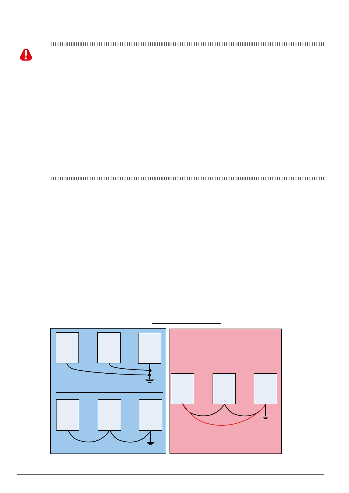
4. When using more than one inverter, be careful not to loop the ground wire, as shown below in Fig. 3.12.1.
Figure3.12.1:InverterGrounding
VDI100 VDI100 VDI100
a) Correct
VDI100 VDI100 VDI100
VDI100 VDI100 VDI100
Loop
c) Incor rect
b) Correct
30 VDI100 • Instruction manual
Page 31

3.13. Input Power and Motor Cable Length
The length of the cables between the input power source and /or the motor and inverter can cause a signicant
phase to phase voltage reduction due to the voltage drop across the cables. The wire size shown in Tables
3.16.1 is based on a maximum voltage drop of 2%. If this value is exceeded, a wire size having larger diameter
may be needed. To calculate phase tot phase voltage drop, apply the following formula:
Phase-to-phasevoltagedrop(V)=√3×resistanceofwire(Ω/km)×lengthofline(m)×current(A)×10-3.
(km=3280xfeet)
(m=3.28xfeet)
3.14. Motor Cable Length vs. Carrier Frequency
The allowable setting of the PWM carrier frequency is also determined by motor cable length and is specied in
the following Table 3.14.1.
Table3.14.1:CableLengthvs.CarrierFrequency
Cable length between
the inverter and
Motor in m (ft.). -100 (100 – 165) (166 - 328) -329
Recommended carrier
frequency allowed
Parameter 11-01
< 30m 30 – 50 50 – 100 > 100
16kHz (max) 10 kHz (max) 5 kHz (max) 2 kHz (max)
3.15. Installing an AC Line Reactor
If the inverter is connected to a large-capacity power source (600kVA or more), install an optional AC reactor on
the input side of the inverter. This also improves the power factor on the power supply side
3.16. Wire Section
The following table shows the recommended wire section for each of the VDI100 models. It depends on the
application whether or not to install a circuit breaker.
Note ! When using a ground protection make sure the current setting is above 200mA and trip delay time is 0.1 sec of higher.
Table3.16.1:
Wiresection
2
Wire section (mm
Class VDI100 Model
230V
1ph / 3ph
230V
3 ph
VDI100 • Instruction manual 31
VDI100-1007-KBX-2T 2,5
VDI100-1015-KBX-2T 2,5
VDI100-2022-KBX-2T 4
VDI100-2037-KBX-2T 6 6
VDI100-2055-KBX-2T 10 6
VDI100-3075-KBX-2T 10 6
VDI100-4110-KBX-2T 16 10
VDI100-4150-KBX-2T 25 10
VDI100-4185-KBX-2T 25 16
VDI100-5220-KXX-2T 35 16
Main circuit
~6 2,5~6 0.5~2,5
~6 4~6 0.5~2,5
~6 4~6 0.5~2,5
(2)
Grounding line
E(G)
~10 0.5~2,5
~10 0.5~2,5
)
Control line
0.5~2,5
0.5~2,5
0.5~2,5
0.5~2,5
0.5~2,5
(3)
Page 32

Class VDI100 Model
Main circuit
(2)
VDI100-1007-KBX-4 2.5~6 2.5~6 0.5~2.5
VDI100-1015-KBX-4
VDI100-1022-KBX-4 2.5
VDI100-2037-KBX-4 2.5
VDI100-2055-KBX-4 4
2.5
~6 4~6 0.5~2.5
~6 4~6 0.5~2.5
~6 4~6 0.5~2.5
~6 4~6 0.5~2.5
VDI100-3075-KBX-4 6 6
VDI100-3110-KBX-4 10 10
VDI100-3150-KBX-4 10 10
400V
3 Ph
VDI100-4185-KBX-4
VDI100-4220-KBX-4 16 10
10 10
VDI100-5300-KBX-4 25 10
VDI100-5370-KXX-4 25 16
VDI100-5450-KXX-4 35 16
VDI100-5550-KXX-4 70 25
VDI100-6750-KXX-4 95 25
VDI100-6900-KXX-4
VDI100-71100-KXX-4
150 25 0.5~2.5
150 25 0.5~2.5
VDI100-71320-KXX-4 240 35
VDI100-71600-KXX-4 300 35
(1): Constant torque rating.
(2): The main circuit terminals: R/L1, S/L2, T/L3, U/T1, V/T2, W/T3, B1/P, B2, -, o,+
(3): Control line is the terminal wire on the control board.
Wire section (mm
Grounding line
E(G)
2
)
Control line
0.5~2.5
0.5~2.5
0.5~2.5
0.5~2.5
0.5~2.5
0.5~2.5
0.5~2.5
0.5~2.5
0.5~2.5
0.5~2.5
0.5~2.5
0.5~2.5
(3)
3.17. Control Circuit Wiring
(1) Separate the wiring for control circuit terminals from main circuit wiring for terminals (R/L1, S/L2, T/L3, U/
T1, V/T2, W/T3).
(2) Separate the wiring for control circuit terminals R1A-R1B-R1C (or R2A, R2C) (Relay outputs) from wiring for
terminals - , A01, A02, GND, DO1, DO2, DOG, +10V, (-10V), AI1, AI2 and GND wiring.
(3) Use shielded twisted-pair cables (#24 - #14 AWG / 0.5 -2 mm2) shown in Fig. 3.17.1 for control circuits to
minimize noise problems. The maximum wiring distance should not exceed 50m (165 ft).
Wrap with insulating Tape
Shield
Ground Shield at Inverter
end ONLY
Fig.3.17.1:ShieldedTwisted-Pair
Twisted Pair
DO NOT Ground Shield at
this end
(4) When the digital multi-function output terminals (DO1, DO2) are connected to an external relay, a free-
wheeling diode should be connected across the relay coil to prevent an inductive voltage spike from damaging the output circuitry as shown in Fig. 3.17.2 below.
DO1, DO2
50 mA max.
Relay Coil
+ 48V max.
Free-wheeling diode
(100V, > 100mA)
VDI100
32 VDI100 • Instruction manual
Page 33
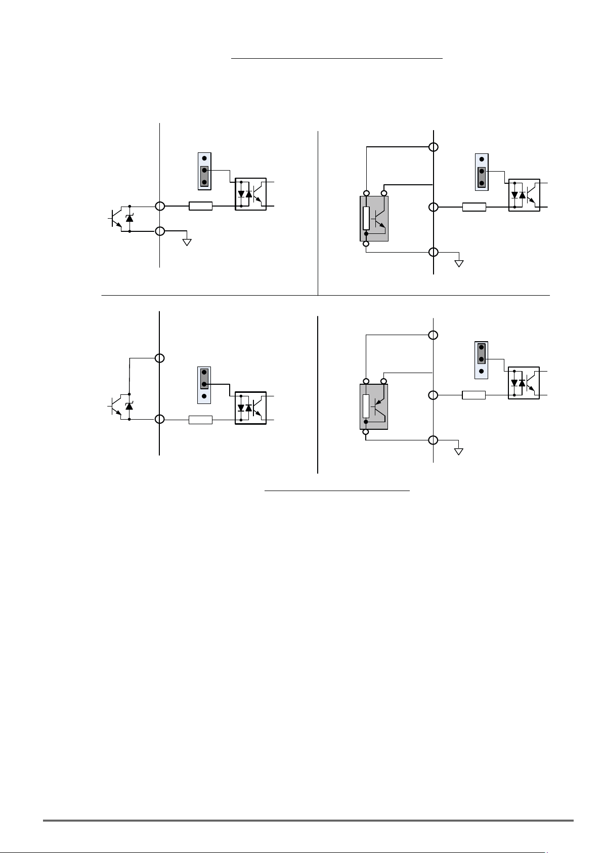
Fig.3.17.2:Photo-CouplerConnectedtoanExternalRelay
Sink Co nfiguration
(5) In Section 3.8 the control boards referenced have a jumper SW3 that can select the digital input to terminals
- , to be set for SINK or SOURCE. The following Fig. 3.17.3 (a.) – (d.) shows examples for the various
SINK / Source interfaces.
SW3
Source
Sink
Input Digital
Terminals S1 - S8
24VG
(a.) Op en Collector Interface
SW3
+24V
Source
Sink
Input Digital
Terminals S1 - S8
Source Configura tion
+24V
SW3
Source
Sink
Input Digital
Terminals S1 - S8
NPN
24VG
(b.) NPN Sensor Interface
+24V
SW3
Source
Sink
Input Digital
Terminals S1 - S8
PNP
24VG
(c.) Op en Collector Interface
Fig.3.17.3:Sink/SourceCongurations
(d.) PN P Sensor Interface
VDI100 • Instruction manual
33
Page 34
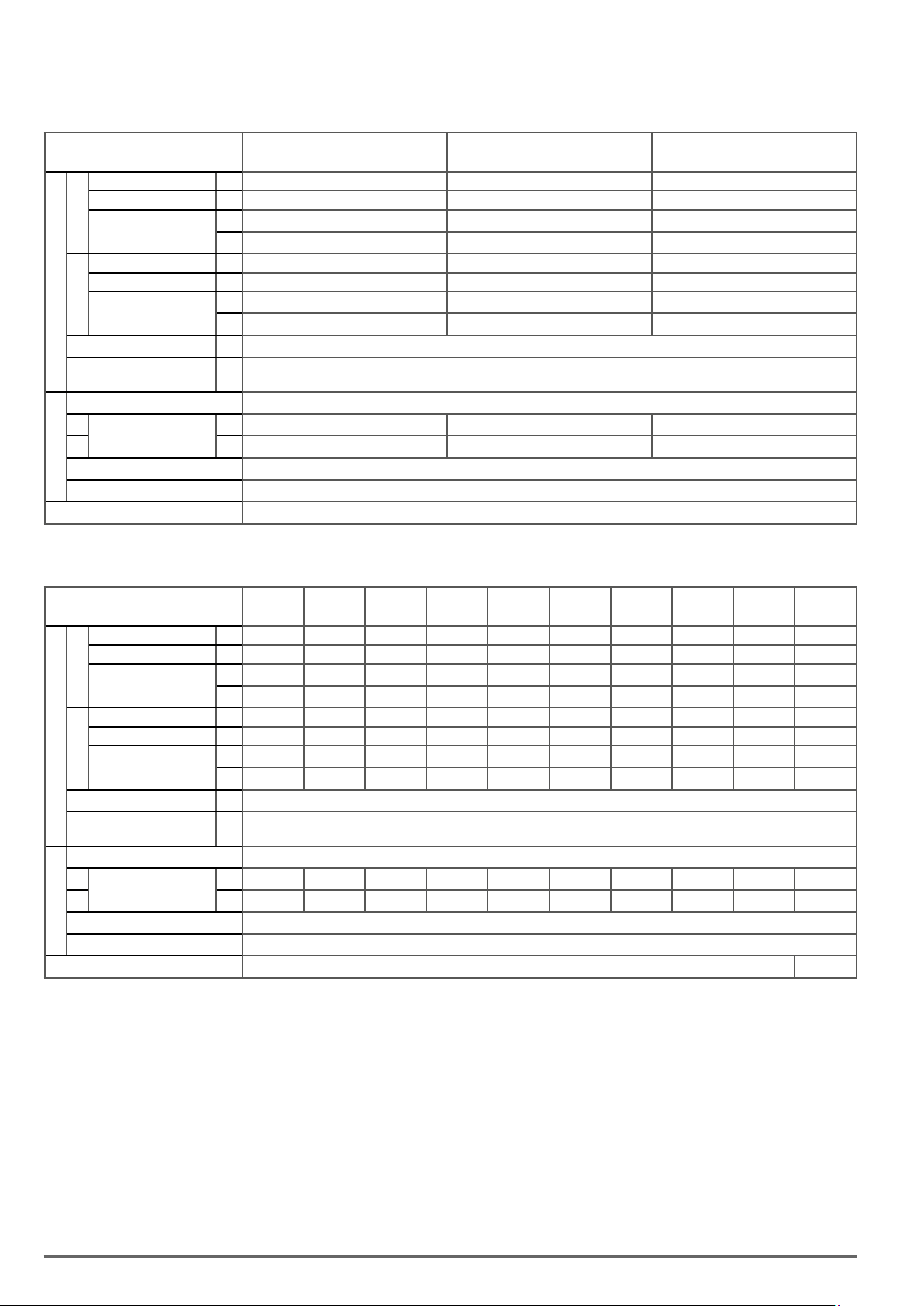
3.18. InverterSpecications
Single-Phase - 230V Class
Sizes VDI100 1007 1015 2022
Rated Output Capacity
Rated Output Current
HD
(3)
Maximum Applicable
(2)
Motor
Rated Output Capacity
Rated Output Current
ND
(4)
Maximum Applicable
Output Rating
Motor
Maximum Output Voltage
Maximum Output
Frequency
(1)
(1)
kVA
HP
kW
kVA
HP
kW
Hz
1.9 3 4.2
A
5 8 11
1 2 3
0.75 1.5 2.2
2.3 3.7 4.6
A
6 9.6 12
2 3 5
1.5 2.2 3.7
V
Three-Phase, 200V to 240V
0.1~599 (Based on parameter setting)
Rated Voltage, Frequency Single-Phase, 200V to 240V, 50/60Hz
HD
Rated Input Current
ND
Allowable Voltage Fluctuation -15% ~ +10%
Input Power
A
A
9.4 14.7 20.3
11.3 17.9 22.1
Allowable Frequency Fluctuation ±5%
Braking Transistor Built-in
Three phase - 230V Class
Sizes VDI100 1007 1015 2022 2037 2055 3075 4110 4150 4185 5220
Rated Output Capacity
Rated Output Current
HD
(3)
Maximum Applicable
(2)
Motor
Rated Output Capacity
Rated Output Current
ND
(4)
Maximum Applicable
Output Rating
Motor
Maximum Output Voltage
Maximum Output
Frequency
(1)
(1)
kVA
1.9 3 4.2 6.7 9.5 12.6 17.9 22.9 27.8 32.4
A
5 8 11 17.5 25 33 47 60 73 85
HP
1 2 3 5 7.5 10 15 20 25 30
kW
0.75 1.5 2.2 3.7 5.5 7.5 11 15 18.5 22
kVA
2.3 3.7 4.6 8.4 11.4 16.0 21.3 26.3 30.1 41.9
A
6 9.6 12 22 30 42 56 69 80 110
HP
2 3 5 7.5 10 15 20 25 30 40
kW
1.5 2.2 3.7 5.5 7.5 11 15 18.5 22 30
V
Hz
Three-Phase, 200V to 240V
0.1~599 (Based on parameter setting)
Rated Voltage, Frequency Three-Phase, 200V to 240V, 50/60Hz
HD
Rated Input Current
ND
Allowable Voltage Fluctuation -15% ~ +10%
Input Power
A
5.4 8.5 11.7 18.7 26.3 34.5 51.1 65.2 79.4 92.4
A
6.5 9.6 12.8 22.3 31.6 41.7 60.9 75.0 85.9 119.6
Allowable Frequency Fluctuation ±5%
Braking Transistor Built-in (6)
34 VDI100 • Instruction manual
Page 35
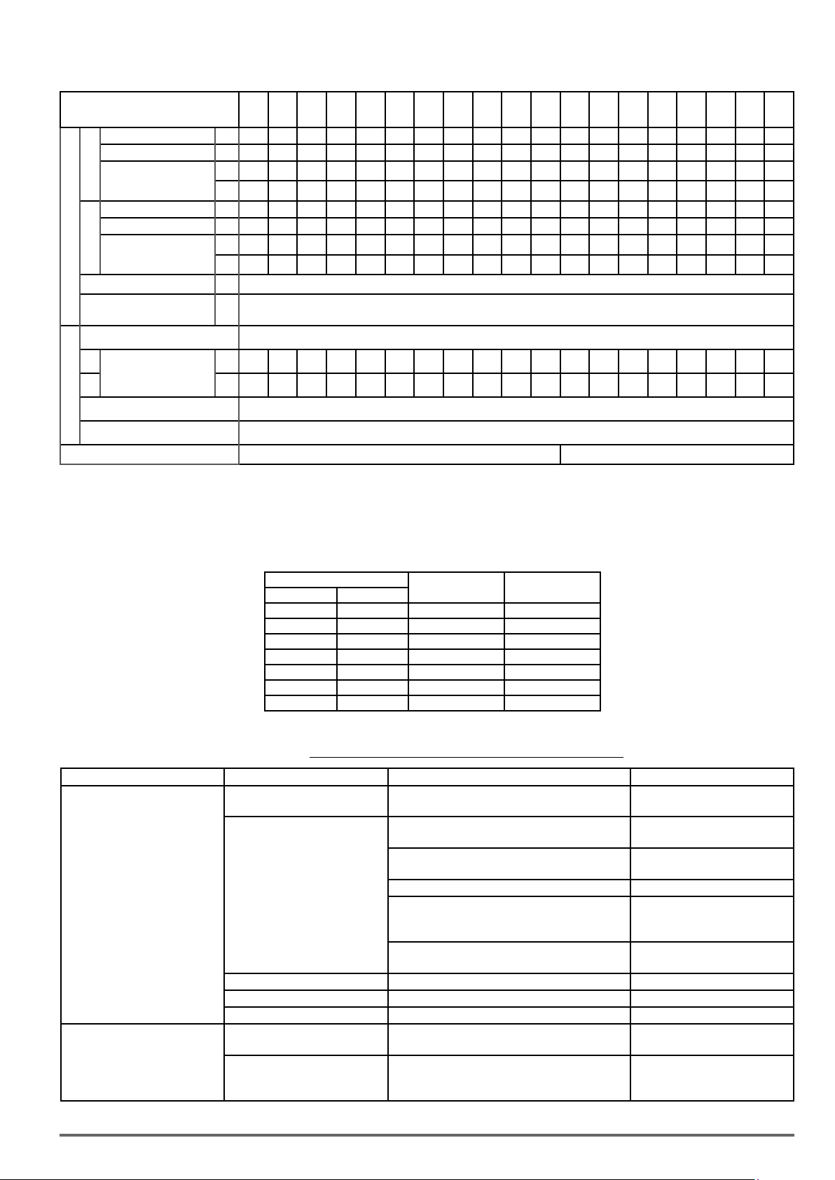
Three phase - 400V Class
Sizes VDI100
Rated Output Capacity
Rated Output Current
HD
(3)
Maximum Applicable
(2)
Motor
Rated Output Capacity
Rated Output Current
ND
(4)
Maximum Applicable
Output Rating
Motor
Maximum Output Voltage
Maximum Output
Frequency
(1)
(1)
1007
1015
1022
2037
2055
3075
3110
3150
4185
4220
5300
5370
5450
5550
6750
6900
4150-F
kVA
2.6 3.2 4.2 7 11.3 13.7 18.3 23.6 29.7 34.3 45.7 57.2 69.3 85.4 114 137 165 198 225
A
3.4 4.2 5.5 9.2 14.8 18 24 31 39 45 60 75 91 118 150 180 216 260 295
HP
1 2 3 5 7.5 10 15 20 25 30 40 50 60 75 100 125 150 175 215
kW
0.75 1.5 2.2 3.7 5.5 7.5 11 15 18.5 22 30 37 45 55 75 90 110 132 160
kVA
3.1 4.1 5.3 9.2 13.3 17.5 23.6 29.0 33.5 44.2 55.6 67.1 78.5 111 128 159 191 226 250
A
4.1 5.4 6.9 12.1 17.5 23 31 38 44 58 73 88 103 145 168 208 250 296 328
HP
2 3 5 7.5 10 15 20 25 30 40 50 60 75 100 125 150 175 210 250
kW
1.5 2.2 3.7 5.5 7.5 11 15 18.5 22 30 37 45 55 75 90 110 132 160 185
V
Hz
Three-Phase, 380V to 480V
0.1~599 (Based on parameter setting)
71100
71320
Rated Voltage, Frequency Three-Phase, 380V to 480V, 50/60Hz
A
HD
Rated Input Current
ND
Input Power
Allowable Voltage Fluctuation -15% ~ +10%
3.7 5.3 6.0 9.6 15.5 18.7 25.0 33.7 42.4 48.9 65.2 81.5 98.9 130 159 181 229 275 325
A
4.5 5.9 7.5 11.6 18.2 24.0 32.3 41.3 47.8 58.7 78.3 95.7 112 159 181 229 275 325 361
Allowable Frequency Fluctuation ±5%
Braking Transistor Built-in Option (External Braking Module)
(1) Based on the standard 4-pole induction motor. The selected inverter must have a higher output current rating than the motor.
(2) The default setting of VDI100 is HD (heavy duty mode). To switch VDI100 to ND (normal duty mode) set parameter (00-27) to 1. When switching to ND (normal duty mode),
the frequency will change to 2kHz.
(3) The default setting of carrier frequency in HD mode is shown into the table below, if the setting value is higher than default setting, derating may be required.
(4) The default setting of carrier frequency in ND mode is 2kHz, if the setting value is higher than default setting, de-rating may be required.
(5) If control mode is set to SLV mode (*) and maximum frequency is larger than 80Hz, the carrier frequency range is 2~8kHz.
(6) Option (External Braking Module)
71600
Inverter Voltage and Power HD mode carrier freq
230V Class 400V Class
0.75 ~ 15 kW 0.75 ~ 22 kW 2~16 kHz 8 kHz
18.5 kW - 2~12 kHz 6 kHz
22 kW - 2~12 kHz
- 30 ~ 37 kW 2~12 kHz
- 45 ~ 132 kW 2~10 kHz
- 90 kW 2~10 kHz 4 kHz
- 160 kW 2~8 kHz 3 kHz
range
The following table shows maximum output frequency for each control mode.
Table3.18.1:Maximumoutputfrequencyforeachcontrolmode
Duty Cycle Control mode (*) Other settings Maximum output frequency
V/f
V/f + PG, SLV2
Heavy Duty
SLV
(00-27=0)
SV
PMSV
PMSLV
V/f
Normal Duty
(00-27=1)
V/f + PG
SLV /SV
PMSV/ PMSLV
SLV2
(*) See PAR 00-00 Control mode selection (ch. “4.4. Description of Parameters” on page 95).
maximum frequency set to 599Hz 599Hz
230V Class: 0.75~7.5 kW,
400V Class: 0.75~11 kW
230V Class: 11~18.5 kW,
400V Class: 18.5 ~ 22 kW 100Hz
400V Class: 30~160kW carrier (11-01) is set as 8K
400V Class: 30~132kW carrier (11-01) is above 8K
maximum frequency set to 599Hz 599Hz
No normal duty mode
HD mode carrier
freq default setting
(5)
(5)
(5)
5 kHz
5 kHz
5 kHz
150Hz
400V Class: 15 kW
110Hz
230V Class: 22 kW,
100Hz
or below 8K
230V Class: 22 kW,
80Hz
Full range 400Hz
Full range Twice of Base frequency
Full range Base frequency
VDI100 • Instruction manual 35
Page 36
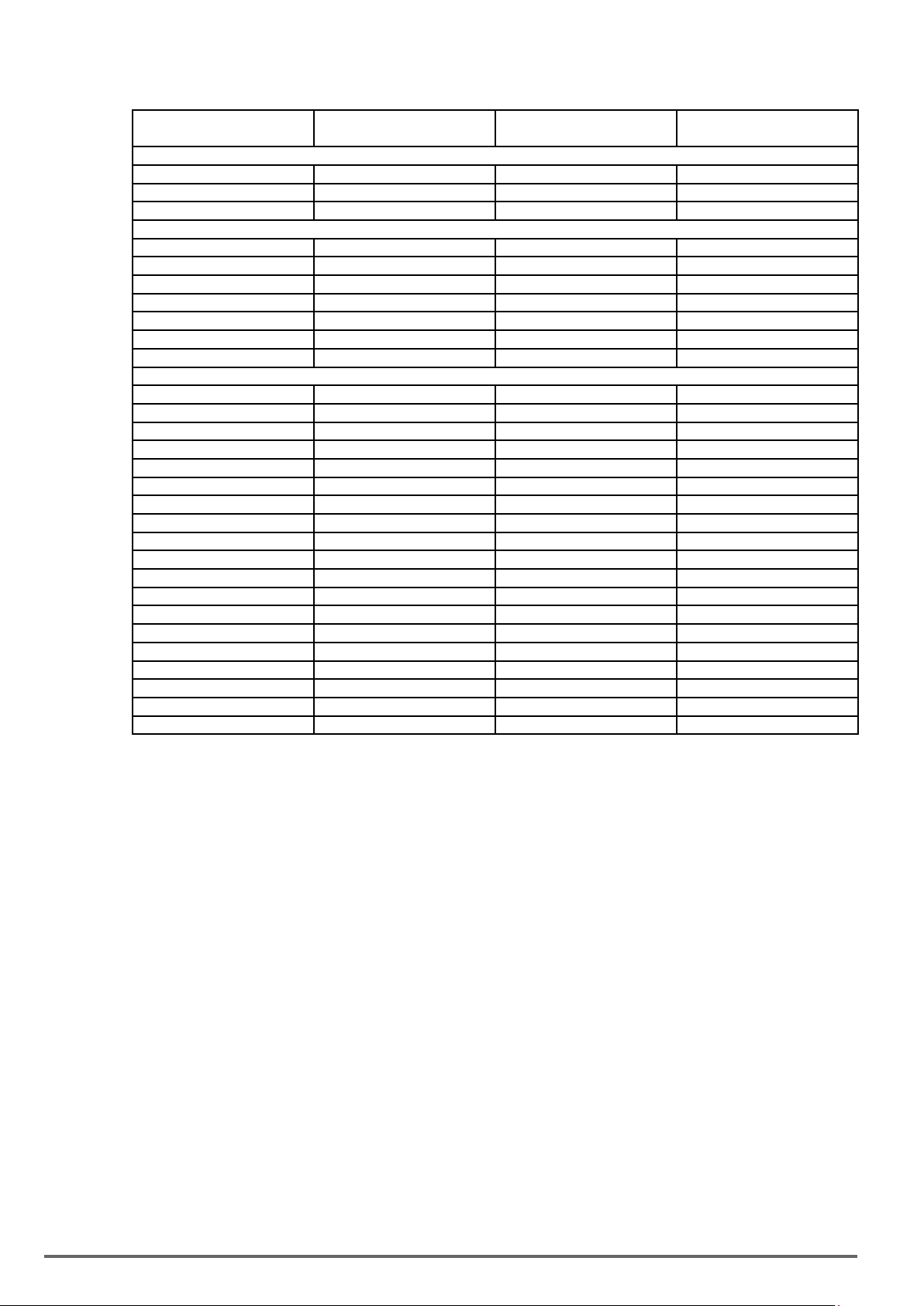
3.18.1. Powerloss
Drive Model
VDI100-1007-...-2T-… 107,0 92,0 8
VDI100-1015-...-2T-… 145,5 125,1 8
VDI100-2022-...-2T-… 166,6 143,3 8
VDI100-2037-...-2T-… 288,0 247,7 8
VDI100-2055-...-2T-… 461,2 396,6 8
VDI100-3075-...-2T-… 600,3 516,3 8
VDI100-4110-...-2T-… 733,1 630,5 8
VDI100-4150-...-2T-… 961,7 827,1 8
VDI100-4185-...-2T-… 1021,3 878,3 6
VDI100-5220-...-2T-… 1562,7 1343,9 5
VDI100-1007-...-4-… 127,4 109,6 8
VDI100-1015-...-4-… 134,7 115,8 8
VDI100-1022-...-4-… 171,7 147,7 8
VDI100-2037-...-4-… 241,9 208,0 8
VDI100-2055-...-4-… 294,1 252,9 8
VDI100-3075-...-4-… 697,7 600,0 8
VDI100-3110-...-4-… 829,7 713,5 8
VDI100-3150-...-4-… 880,5 757,2 8
VDI100-4185-...-4-… 1109,4 954,1 8
VDI100-4220-...-4-… 1172,5 1008,4 8
VDI100-5300-...-4-… 1666,5 1433,2 5
VDI100-5370-...-4-… 1965,9 1690,7 5
VDI100-5450-...-4-… 2562,8 2204,0 5
VDI100-5550-...-4-… 1755,0 1509,3 5
VDI100-6750-...-4-… 1955,0 1681,3 5
VDI100-6900-...-4-… 2260,0 1943,6 5
VDI100-71100-...-4-… 1660,0 1427,6 5
VDI100-71320-...-4-… 2060,0 1771,6 5
VDI100-71600-...-4-… 2560,0 2201,6 3
Watt Loss Heat Loss Carrier Frequency
(W) (kcal/hr) (kHz)
Single phase / Three phase - 230V Class
Three phase - 230V Class
Three phase - 400V Class
36 VDI100 • Instruction manual
Page 37
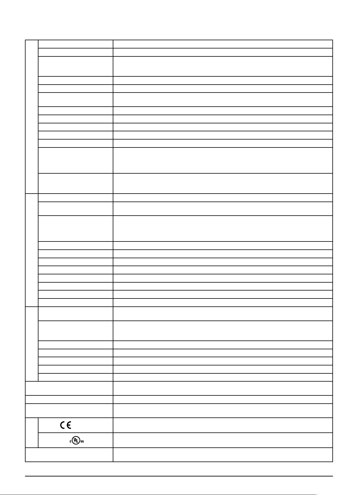
3.18.2. General Specications
Motor type Asynchronous Motor, Surface Permanent Magnet Motor, Interior Permanent Magnet Motor
Control Modes V/f, V/f+Encoder, SLV (vector control open loop), SV (vector control closed loop), PMSLV, PMSV
±1% (SLV, overload 200% and control range 1 : 30 (60....2Hz ; 50...1.6Hz)),
Speed control accuracy
±1.5% (V/f open-loop, overload 150% and control range 1 : 40 / 60....1.5Hz ; 50...1.25Hz), ±0.1% (SV)
Output Frequency 0.1Hz~599Hz
Output Frequency Resolution 0.01Hz
Overload Tolerance
Frequency Setting Signal 0 to +10V, -10V to +10V, 4 to 20mA or pulse train input
Acceleration / Deceleration Time 0.0 ~ 6000.0 sec (separate acceleration and deceleration time set)
Voltage / Frequency Characteristics 15 fixed + one customized V/f pattern
Control Characteristics
Inverter Overload Protection (OL2)
Motor Overload Protection (OL1) Electrical overload protection curve
Protection Functions
Momentary Power Loss Restart When Power loss exceeds 15ms. This function can be set up to 2 sec
Output Phase Loss Protection (OPL) If the OPL function acts, the motor stops rotation automatically
Environment
Specification
Braking Unit Built-in braking transistor on 3ph 400V Class 0.75-30kW HD and on (1ph)/3ph 230V Class 0.75-18.5kW HD
Display LED keypad with 5-digits 7-segment display (LCD keypad option)
Main Control Functions
Other Functions
Stall Prevention During Acceleration, Deceleration and continuous run
Over Current (OC) and Output
Short-Circuit (SC) Protection
Over Voltage Protection (OV) OV threshold = 410Vdc (230V class), 820Vdc (400V class)
Under Voltage (UV) UV threshold = 190Vdc (230V class), 380Vdc (400V class)
Overheat Protection (OH) Thermistor sensor on heatsink
Ground Fault Protection (GF) Protection by current detection circuit
Charge Indicator When main circuit DC voltage ≥ 50V, the CHARGE LED is on
Protection degree
Operating Temperature
Storage Temperature -20 ~ +70°C
Humidity 95% RH or less (no condensation)
Altitude Altitude of 1000 meters or lower
Vibration 1.0G, in compliance with IEC 60068-2-6
Pollution Degree Meet IEC 60721-3-3 Class 3C2
Communication Function
DC choke Built-in on 3ph 400V Class 75-160kW HD
EMC filter
RoHS
Heavy Duty Mode (HD.): 150% rated current for 60sec, 200% rated current for 2 sec. (Factory default)
Auto-tuning, Zero Servo, Torque Control, Position Control, Droop, Soft-PWM, Over-Voltage Protection, Dynamic
Braking, Speed Search, Frequency Traversing, Momentary Power Loss Restart, PID Control, Automatic Torque
Compensation, Slip Compensation, RS-485 Communication, Close Loop Control with encoder, Simple PLC Func-
Records of Power ON and Operation Time, 30 Fault History Records and Latest Fault State Record, Energy-Saving
Function, Phase Loss Protection, DC Braking, Mechanical Brake Control, Dwell, S Curve Acceleration and Decelera-
Heavy Duty Mode (HD.): 150% rated current for 60sec, 200% rated current for 2 sec. (Factory default), Carrier
±1% (SLV, overload 150% and control range 1 : 50 (60....1.2Hz ; 50...1Hz)),
Normal Duty Mode (ND.): 120% rated current for 60sec
tion, 2 Analog Output, Torque-Off function, Application Presets
tion, Pulse input / output, Display of Engineering Unit, NPN / PNP Selection
When the current exceeds 200% of the inverter rated current
Inverter stops when the output is higher than below conditions.
frequency is from 2kHz to 8kHz
Normal Duty Mode (ND.): 120% rated current for 60sec, Carrier frequency is 2kHz
Sizes 1 to 5: IP20 / NEMA 1, with standard removable anti dust cover
Sizes 6-7: IP00; available optional NEMA 1 kit (cover and conduit box)
-10~+50°C (Sizes 1 to 5 without anti dust cover; sizes 6 -7)
-10~+40°C (Sizes 1 to 5 with anti dust cover; sizes 6 -7 with NEMA 1 kit)
Up to +60°C with derating.
Built-in: RS-485 with Modbus RTU / ASCII (standard RJ45 connection)
Optional: Profibus/CANopen/DeviceNet/TCP-IP
Add-on module on –F version 3ph 400V Class 0.75-45kW HD
In compliance with EN61800-3:2012 standard
In compliance with EN61800-3 (EMC) and EN61800-5-1(LVD)
Conformity to RoHS directive
Certification
Encoder expansion card (optional)
VDI100 • Instruction manual 37
Asynchronous Motor: Digital incremental Line driver and Open collector
PM motor: Digital incremental Line driver, Resolver, SinCos
UL508C
Page 38

3.19. Inverter Derating Based on Carrier Frequency
0 2kHz 8kHz 16kHz
0 2kHz 6kHz 12kHz
0 2kHz 5kHz 12kHz
230V Class
0.75 ~ 15 kW 18.5 kW
ND
HD
80% of HD
ND
HD
80% of HD
Iout
Iout
22 kW
Iout
ND
HD
80% of HD
Fc
Fc
Fc
400V Class
0.75 ~ 22 kW 30 ~ 37 kW
Iout
ND
HD
60% of HD
Fc
0 2kHz 8kHz 16kHz
80% of HD
45 ~ 132 kW 90 kW
Iout
ND
HD
70% of HD
70% of HD
Iout
ND
HD
Fc
0 2kHz 5kHz 12kHz
Iout
ND
HD
Fc
0 2kHz 5kHz 10kHz
Fc
0 2kHz 4kHz 10kHz
38 VDI100 • Instruction manual
Page 39

ND
HD
70% of HD
160 kW
Iout
0 2kHz 3kHz 8kHz
Fc
3.20. Inverter Derating Based on Temperature
Iout
ND
HD
80% of ND
80% of HD
Temperatur e
60°C
ND
HD
60% of ND
60% of HD
Iout
0
50°C
IP00 and IP20 without anti-dust covers:
>50 °C up to Max.60 °C, 2% derate per °C.
IP20 with anti-dust covers and IP00+NEMA1 kit:
>40 °C up to Max.60 °C, 2% derate per °C.
0 40°C 60°C
Temperature
3.21. Inverter Derating Based on Altitude
100%
90%
80%
Rated current
0
1000m
2000m
Altitude
3000m
VDI100 • Instruction manual 39
Page 40
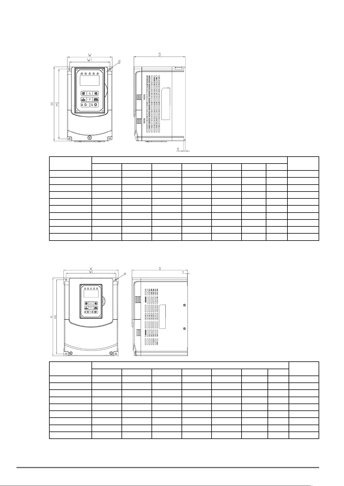
3.22. Inverter Dimensions
Sizes1and2(IP20/NEMA1)
Inverter Model
VDI100-1007-KBX-2T 130 (5.12) 215 (8.46) 150 (5.91) 118 (4.65) 203 (7.99) 5 (0.20) M5 2.2 (4.9)
VDI100-1015-KBX-2T 130 (5.12) 215 (8.46) 150 (5.91) 118 (4.65) 203 (7.99) 5 (0.20) M5 2.2 (4.9)
VDI100-2022-KBX-2T 140 (5.51) 279 (10.98) 177 (6.97) 122 (4.80) 267 (10.51) 7 (0.28) M6 3.8 (8.4)
VDI100-2037-KBX-2T 140 (5.51) 279 (10.98) 177 (6.97) 122 (4.80) 267 (10.51) 7 (0.28) M6 3.8 (8.4)
VDI100-2055-KBX-2T 140 (5.51) 279 (10.98) 177 (6.97) 122 (4.80) 267 (10.51) 7 (0.28) M6 3.8 (8.4)
VDI100-1007-KBX-4 130 (5.12) 215 (8.46) 150 (5.91) 118 (4.65) 203 (7.99) 5 (0.20) M5 2.2 (4.9)
VDI100-1015-KBX-4 130 (5.12) 215 (8.46) 150 (5.91) 118 (4.65) 203 (7.99) 5 (0.20) M5 2.2 (4.9)
VDI100-1022-KBX-4 130 (5.12) 215 (8.46) 150 (5.91) 118 (4.65) 203 (7.99) 5 (0.20) M5 2.2 (4.9)
VDI100-2037-KBX-4 140 (5.51) 279 (10.98) 177 (6.97) 122 (4.80) 267 (10.51) 7 (0.28) M6 3.8 (8.4)
VDI100-2055-KBX-4 140 (5.51) 279 (10.98) 177 (6.97) 122 (4.80) 267 (10.51) 7 (0.28) M6 3.8 (8.4)
W H D W1 H1 t d
Dimensions in mm (inch)
Net Weight kg
(lbs)
Sizes3and4(IP20/NEMA1)
Inverter Model
VDI100-3075-KBX-2T 210 (8.27) 300 (11.81) 215 (8.46) 192 (7.56) 286 (11.26) 1.6 (0.06) M6 6.2 (13.67)
VDI100-4110-KBX-2T 265 (10.43) 360 (14.17) 225 (8.86) 245 (9.65) 340 (13.39) 1.6 (0.06) M8 10 (22.05)
VDI100-4150-KBX-2T 265 (10.43) 360 (14.17) 225 (8.86) 245 (9.65) 340 (13.39) 1.6 (0.06) M8 10 (22.05)
VDI100-4185-KBX-2T 265 (10.43) 360 (14.17) 225 (8.86) 245 (9.65) 340 (13.39) 1.6 (0.06) M8 10 (22.05)
VDI100-3075-KBX-4 210 (8.27) 300 (11.81) 215 (8.46) 192 (7.56) 286 (11.26) 1.6 (0.06) M6 6.2 (13.67)
VDI100-3110-KBX-4 210 (8.27) 300 (11.81) 215 (8.46) 192 (7.56) 286 (11.26) 1.6 (0.06) M6 6.2 (13.67)
VDI100-3150-KBX-4 210 (8.27) 300 (11.81) 215 (8.46) 192 (7.56) 286 (11.26) 1.6 (0.06) M6 6.2 (13.67)
VDI100-4185-KBX-4 265 (10.43) 360 (14.17) 225 (8.86) 245 (9.65) 340 (13.39) 1.6 (0.06) M8 10 (22.05)
VDI100-4220-KBX-4 265 (10.43) 360 (14.17) 225 (8.86) 245 (9.65) 340 (13.39) 1.6 (0.06) M8 10 (22.05)
W H D W1 H1 t d
Dimensions in mm (inch)
Net Weight
kg (lbs)
40 VDI100 • Instruction manual
Page 41

Size5(IP20/NEMA1)
Inverter Model
VDI100-5220-KXX-2T 286.5 (11.29) 525 (20.67) 252 (9.92) 220 (8.66) 505 (19.88) 3.3 (0.13) M8 30 (66.14)
VDI100-5300-KBX-4 286.5 (11.29) 525 (20.67) 252 (9.92) 220 (8.66) 505 (19.88) 3.3 (0.13) M8 30 (66.14)
VDI100-5370-KXX-4 286.5 (11.29) 525 (20.67) 252 (9.92) 220 (8.66) 505 (19.88) 3.3 (0.13) M8 30 (66.14)
VDI100-5450-KXX-4 286.5 (11.29) 525 (20.67) 252 (9.92) 220 (8.66) 505 (19.88) 3.3 (0.13) M8 30 (66.14)
VDI100-5550-KXX-4 286.5 (11.29) 525 (20.67) 252 (9.92) 220 (8.66) 505 (19.88) 3.3 (0.13) M8 35 (77.16)
W H D W1 H1 t d
Dimensions in mm (inch)
Net Weight
kg (lbs)
Sizes6and7(IP00)
Inverter Model
VDI100-6750-KXX-4 344 (13.54) 580 (22.83) 300 (11.81) 250 (9.84) 560 (22.05) 1.6 (0.06) M8 46.7 (102.96)
VDI100-6900-KXX-4 344 (13.54) 580 (22.83) 300 (11.81) 250 (9.84) 560 (22.05) 1.6 (0.06) M8 46.7 (102.96)
VDI100-71100-KXX-4 459 (18.07) 790 (31.10) 324.5 (12.78) 320 (12.60) 760 (29.92) 1.6 (0.06) M10 88 (194.01)
VDI100-71320-KXX-4 459 (18.07) 790 (31.10) 324.5 (12.78) 320 (12.60) 760 (29.92) 1.6 (0.06) M10 88 (194.01)
VDI100-71600-KXX-4 459 (18.07) 790 (31.10) 324.5 (12.78) 320 (12.60) 760 (29.92) 1.6 (0.06) M10 88 (194.01)
VDI100 • Instruction manual 41
W H D W1 H1 t d
Dimensions in mm (inch)
Net Weight
kg (lbs)
Page 42

Sizes6and7+NEMA1kit(IP20/NEMA1)
Inverter Model
VDI100-6750-KXX-4
+ NEMA 1 kit for VDI100
VDI100-6900-KXX-4
+ NEMA 1 kit for VDI100
VDI100-71100-KXX-4
+ NEMA 1 kit for VDI100
VDI100-71320-KXX-4
+ NEMA 1 kit for VDI100
VDI100-71600-KXX-4
+ NEMA 1 kit for VDI100
Dimensions in mm (inch)
W H D W1 H1 t d
348.5 (13.72) 740 (29.13) 300 (11.81) 250 (9.84) 560 (22.05) 1.6 (0.06) M8 49.7 (109.57)
348.5 (13.72) 740 (29.13) 300 (11.81) 250 (9.84) 560 (22.05) 1.6 (0.06) M8 49.7 (109.57)
463.5 (18.25) 1105 (43.50) 324.5 (12.78) 320 (12.60) 760 (29.92) 1.6 (0.06) M10 94.4 (208.12)
463.5 (18.25) 1105 (43.50) 324.5 (12.78) 320 (12.60) 760 (29.92) 1.6 (0.06) M10 94.4 (208.12)
463.5 (18.25) 1105 (43.50) 324.5 (12.78) 320 (12.60) 760 (29.92) 1.6 (0.06) M10 94.4 (208.12)
Net Weight
kg (lbs)
42 VDI100 • Instruction manual
Page 43

3.23. Dimensions for Models with Add-onlter
Sizes 1 and 2
Inverter Model
VDI100-1007 130 (5.12) 306 (12.05) 150 (5.91) 118 (4.65) 203 (7.99) 215 (8.46) 5 M5 3.5 (7.71)
VDI100-1015 130 (5.12) 306 (12.05) 150 (5.91) 118 (4.65) 203 (7.99) 215 (8.46) 5 M5 3.5 (7.71)
VDI100-1022 130 (5.12) 306 (12.05) 150 (5.91) 118 (4.65) 203 (7.99) 215 (8.46) 5 M5 3.5 (7.71)
VDI100-2037 140 (5.51) 400 (15.75) 177 (6.97) 122 (4.80) 267 (10.51) 279 (10.98) 7 M6 5.5 (12.13)
VDI100-2055 140 (5.51) 400 (15.75) 177 (6.97) 122 (4.80) 267 (10.51) 279 (10.98) 7 M6 5.5 (12.13)
W H D W1 H1 H2 t d
Dimensions in mm (inch)
Net Weight
kg (lbs)
Sizes 3 and 4
Inverter Model
VDI100-3075 210 (8.27) 416.5 (16.40) 215 (8.46) 192 (7.56) 286 (11.26) 300 (11.81) 1.6 (0.06) M6 8.0 (17.63)
VDI100-3110 210 (8.27) 416.5 (16.40) 215 (8.46) 192 (7.56) 286 (11.26) 300 (11.81) 1.6 (0.06) M6 8.0 (17.63)
VDI100-4150 265 (10.43) 500 (19.69) 225 (8.86) 245 (9.65) 340 (13.39) 360 (14.17) 1.6 (0.06) M8 12.5 (27.56)
VDI100-4185 265 (10.43) 500 (19.69) 225 (8.86) 245 (9.65) 340 (13.39) 360 (14.17) 1.6 (0.06) M8 12.5 (27.56)
VDI100-4220 265 (10.43) 500 (19.69) 225 (8.86) 245 (9.65) 340 (13.39) 360 (14.17) 1.6 (0.06) M8 12.5 (27.56)
VDI100 • Instruction manual 43
W H D W1 H1 H2 t d
Dimensions in mm (inch)
Net Weight
kg (lbs)
Page 44

Size 5
Inverter Model
VDI100-5300 286.5 (11.28) 679 (26.73) 252 (9.92) 220 (8.66) 505 (19.88) 525 (20.67) 3.3 (0.13) M8 32.5 (71.65)
VDI100-5370-KXX-4-F 286.5 (11.28) 679 (26.73) 252 (9.92) 220 (8.66) 505 (19.88) 525 (20.67 3.3 (0.13) M8 32.5 (71.65)
VDI100-5450-KXX-4-F 286.5 (11.28) 679 (26.73) 252 (9.92) 220 (8.66) 505 (19.88) 525 (20.67 3.3 (0.13) M8 32.5 (71.65)
W H D W1 H1 H2 t d
Dimensions in mm (inch)
Net Weight
kg (lbs)
44 VDI100 • Instruction manual
Page 45

4. Keypad and Programming Functions
4.1. LED Keypad (KB-LED-VDI100)
4.1.1. Keypad Display and Keys
Reverse Direction
Forward Direction
Status Indicator
Fault Status
Indicator
Status Indicator
External Sequence
Indicator
External Reference
Indicator
5 Digit, 7 Segment
LED Display
8 button
Run Status
Membrane Keypad
Indicator
Stop Status
Indicator
DISPLAY
5 Digit LED Display Monitor inverter signals, view / edit parameters, fault / alarm display.
LED INDICATORS
FAULT LED ON when a fault or alarm is active.
FWD LED ON when inverter is running in forward direction, flashing when stopping.
REV On when inverter is running in reverse direction, flashing when stopping.
SEQ LED ON when RUN command is from the external control terminals or from serial communication
REF LED ON when Frequency Reference command is from the external control terminals or from serial communication
KEYS (8) Description
RUN RUN Inverter in Local Mode
STOP STOP Inverter
▲
▼
FWD/REV Used to switch between Forward and Reverse direction
DSP/FUN Used to scroll to next screen
◄ / RESET Selects active seven segment digit for editing with the ▲▼keys
READ / ENTER Used to read and save the value of the active parameter
Parameter navigation Up, Increase parameter or reference value
Parameter navigation down, decrease parameter or reference value
Frequency screen -> Function selection -> Monitor parameter
Used to reset fault condition.
Auto-Repeat Keys
Holding the ▲UP or ▼DOWN key for a longer period of time will initiate the auto-repeat function resulting in
the value of the selected digit to automatically increase or decrease.
VDI100 • Instruction manual 45
Page 46

4.1.2. Seven Segment Display Description
Actual LED Display Actual LED Display Actual LED Display Actual LED Display
0
1
2
3
4
5
6
7
8
9
Display output frequency Frequency Reference Set Frequency Reference
0
1
2
3
4
5
6
7
8
9
LED lights on LED flashes Flashing digit
A
B
C
D P
E
F
G S
H
I
J
a
c
e
f
h
i
j
L
n -
o
l
o
p
q .
r
s
t
u
V
u
Y
°
_
y
-
.
At power-up, the display will show the frequency reference setting and all LEDs are ashing. Press the ▲ (UP)
or ▼ (DOWN) key to enter the frequency reference edit mode, use the ◄/RESET key to select which digit to
edit (ashing). Use the ▲ (UP) or ▼ (DOWN) key to modify the value and press the READ / ENTER key to
save the frequency reference and switch back to the frequency reference display mode.
• During run operation, the display will show the output frequency.
Note ! When in edit mode and the READ / ENTER is not pressed within 5 sec, the inverter will switch back to the frequency reference
display mode.
LED Display Examples
Seven Segment Display Description
1. Displays the frequency reference at power-up.
2. Displays the actual output frequency during run operation.
Displays parameter code.
Displays the setting value of parameter.
Displays input voltage.
Displays inverter current.
Displays DC Bus Voltage.
Displays temperature.
Displays PID feedback value; The displayed digit is set by 12-01.
Error display; refer to chapter 5 Troubleshooting and Maintenance.
Displays AI1/ AI2 input (0~100%)
46 VDI100 • Instruction manual
Page 47

4.1.3. LED Indicator Description
• Fault LED
State Description Led
Off No Fault
Illuminated Fault
or alarm Active
• Forward LED
(FWD)
State Description Led
Off Inverter in reverse direction
Illuminated Inverter is running in forward direction
Flashing Forward direction active, no run command
• Reverse LED
(REV)
State Description Led
Off Inverter in forward direction
Illuminated Inverter is running in reverse direction
Flashing Reverse direction active, no run command
• RUN LED
State Description Led
Off Inverter stopped
Illuminated Inverter running
Flashing Inverter stopped or stopping
• SEQ LED
State Description Led
Off Sequence controlled from keypad
Illuminated Sequence set from external source
• REF LED
State Description Led
Off Frequency reference set from keypad
Illuminated Frequency reference set from external source
Run/StopStatusIndicators
Output Frequency
0
STOP RUN
Frequency
Setting
RUN
STOP
ON
Flashing
STOP
OFF
VDI100 • Instruction manual 47
Page 48

4.1.4. Power-up Monitor
• Power-up
DSP/FUN
After 3 sec.
Display at Power-up Frequency Reference
• Changing Monitor at Power-up
12-00 Display Selection
Highest bit -> 0 0 0 0 0 <- Lowest bit
The setting range for each bit is 0 ~ 7 from the highest bit to the lowest bit.
Range
0: No display 4: Temperature
1: Output current 5: PID feedback
2: Output voltage 6: AI1 value
3: DC voltage 7: AI2 value
Example:12-00=[10000]
After 3 sec.
Display Voltage Class
at Power-up
Output Current
DSP/FUN
DSP/FUN
DSP/FUN
Switch
Mode
Parameter Selection
Parameter Selection
DSP/FUN
Switch
Mode
Frequency Reference
Example:12-00=[12345]
Heatsink Temperature <4>
DSP/FUN
Display Voltage Class
at Power-up
PID Feedback <5>
After 3 sec.
Frequency Reference
DSP/FUN
DSP/FUN
DSP/FUN
Output Voltage <2>
Parameter Selection
DSP/FUN
DSP/FUN
Output Current <1>
DSP/FUN
DC Voltage <3>
48 VDI100 • Instruction manual
Page 49
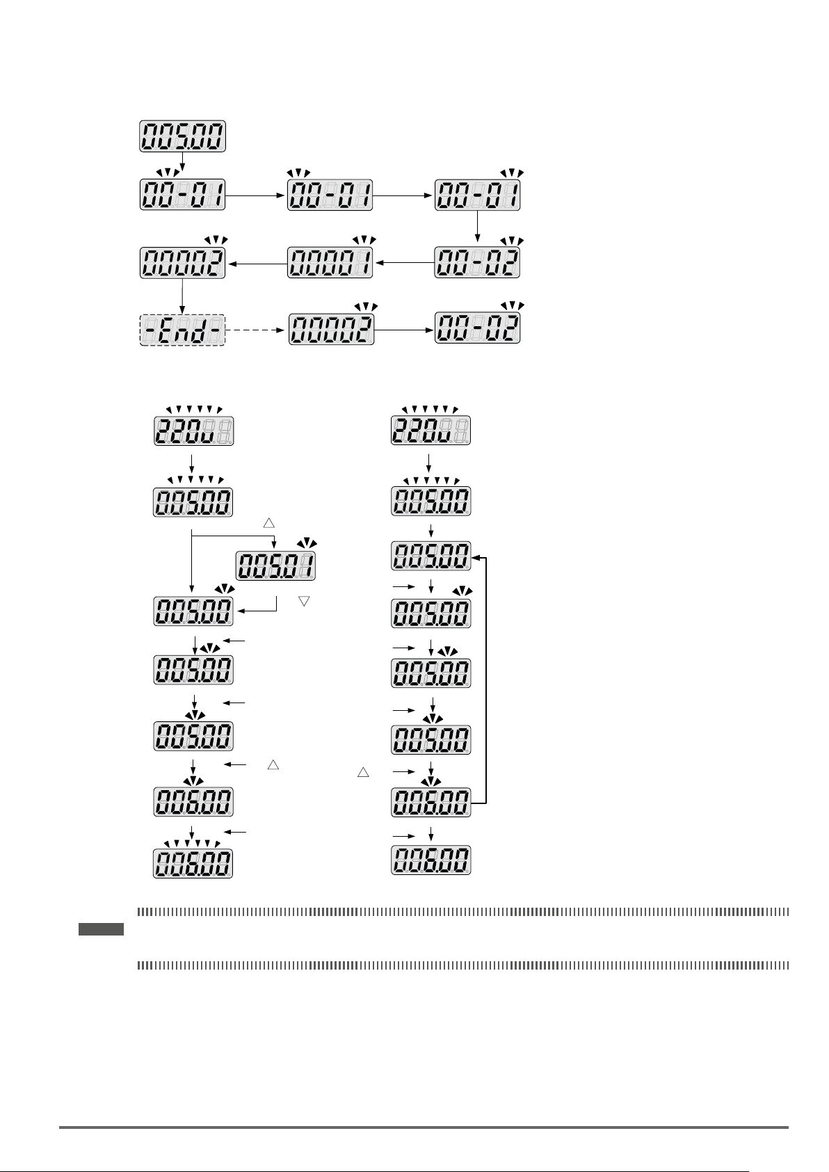
4.1.5. Modifying Parameters/ Set Frequency Reference
Example:ModifyingParameters
Frequency Reference
Press DSP/FUN
Press </RESET
Press
Press READ/ENTER
▲
Flashing
for 3 sec.
Press </RESET
Press
READ/ENTER
Press DSP/FUN
Example:SetFrequencyReference
Press
▲
Display Frequency Reference
1x
1x
Set Frequency Reference 0.1 Hz
1x
Set Frequency Reference 1 Hz
▲
Set Frequency Reference +1 Hz
1x
Display Voltage Class
Flashing for 3 seconds
Press RUN 1x
Output Frequency
Set Frequency Reference
Inverter automatically
reverts back to
display the output
frequency if no
modifications are
made within 5 sec.
Display Voltage Class
Flashing for 3 seconds
Display Frequency Reference
Press </RESET
1x
Set Frequency Reference 0.01 Hz
Set Frequency Reference 0.1 Hz
Set Frequency Reference 1Hz
Set Frequency Reference + 1Hz
Press 1x
▲
Set Frequency Reference
Press 1x
Press </RESET
1x
Press </RESET
1x
Press 1x
▲
Press READ/ENTER
1x
▲
Press </RESET
Press </RESET
Press </RESET
Press 1x
Press READ/ENTER
Set Frequency Reference completed.
Output frequency
Note ! When upper or lower limit is reached during editing of the frequency reference, the edit value will automatically rollover from the
VDI100 • Instruction manual 49
lower limit to the upper limit or from the upper limit to the lower limit.
Page 50

4.1.6. Operation Control
FWD
Indicator
REV
Indicator
RUN
Indicator
Po we r on
RE V co mm an dFW D co mm an dRU N co mm an d RE V co mm an d St op c om ma ndFW D co mm an d
FWDFWD FWD FWD FWD FWD FWD
REV
RUN RUN RUN RUN RUN RUNRUN
REV
Running StoppingStopped
Output Frequency
REV REV
REVREV
REV
Stopped
FWD
REV
RUN
STOP
Indicator
STOP STOP STOP STOP STOP STOP STOP
STOP
50 VDI100 • Instruction manual
Page 51
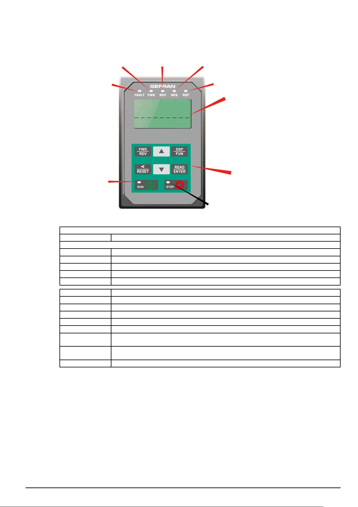
4.2. LCD Keypad(KB-LCD-VDI100)
4.2.1. Keypad Display and Keys
Reverse Direction
Forward Direction
Status Indicator
Fault Status
Indicator
Status Indicator
Monitor
External Sequence
Indicator
External Reference
Indicator
LCD Display
Fref Ref
12-16=005.00Hz
12-17=000.00Hz
12-18=0000.0A
Run Status
Indicator
Stop Status
Indicator
DISPLAY
LCD Display Monitor inverter signals, view / edit parameters, fault / alarm display.
LED INDICATORS
FAULT LED ON when a fault or alarm is active.
FWD LED ON when inverter is running in forward direction, flashing when stopping.
REV On when inverter is running in reverse direction, flashing when stopping.
SEQ LED ON when RUN command is from the external control terminals or from serial communication
REF LED ON when Frequency Reference command is from the external control terminals or from serial communication
8 button
Membrane Keypad
KEYS (8) Description
RUN RUN Inverter in Local Mode
STOP STOP Inverter
▲
▼
FWD/REV Used to switch between Forward and Reverse direction
DSP/FUN Used to scroll to next screen
◄ / RESET Selects active seven segment digit for editing with the ▲▼keys
READ / ENTER Used to read and save the value of the active parameter
Parameter navigation Up, Increase parameter or reference value
Parameter navigation down, decrease parameter or reference value
Frequency screen -> Function selection -> Monitor parameter
Used to reset fault condition.
Auto-Repeat Keys
Holding the ▲UP or ▼DOWN key for a longer period of time will initiate the auto-repeat function resulting in
the value of the selected digit to automatically increase or decrease.
VDI100 • Instruction manual 51
Page 52
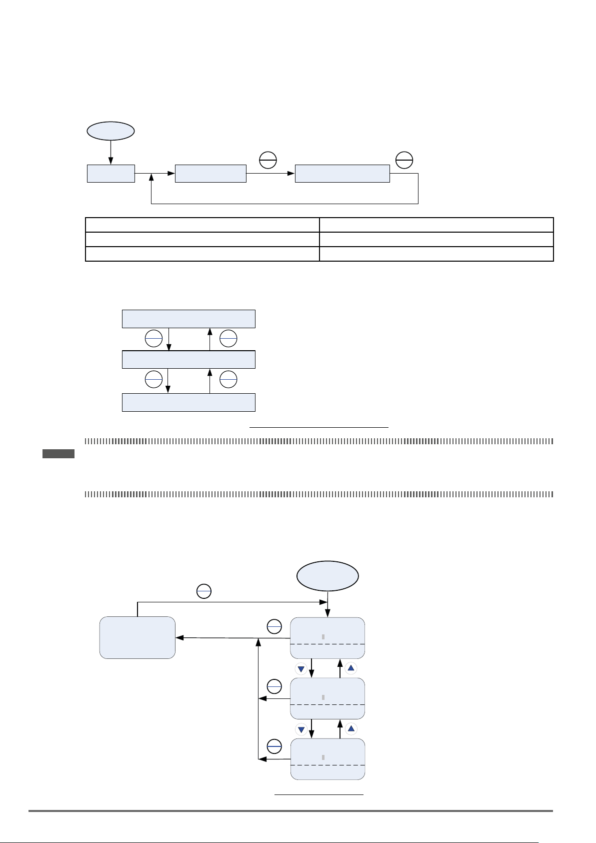
4.2.2. Keypad Menu Structure
Main Menu
The
VDI100 inverter main menu consists of two main groups (modes). The DSP/FUN key is used to switch
between the monitor mode and the parameter group mode.
Power On
Power-up
DSP
FUN
Monitor Mode Parameter Group Mode
DSP
FUN
Mode Description
Monitor Mode View inverter status, signals and fault data.
Parameter Group Mode Access to available parameter groups.
All the available parameter groups are listed in the Parameter Group Mode use the up and down keys to select
a group and press Read/Enter key to access its parameters.
Parameter Group Mode
READ
ENTER
Parameter Mode
READ
ENTER
Parameter Edit Mode
DSP
FUN
DSP
FUN
Select parameter group
Select parameter
Change parameter setting
Fig.4.2.2.1ParameterGroupStructure
Note ! - Always perform an auto-tune on the motor before operating the inverter in vector control (sensorless vector or flux vector).
Auto-tuning mode will not be displayed when the inverter is running or when a fault is active.
- To scroll through the available modes, parameter groups or parameter list press and hold the up or down key.
Monitor Mode
In monitor mode inverter signals can be monitored such as output frequency, output current and output voltage,
etc…) as well as fault information and fault trace. See Fig 4.2.2.2 for keypad navigation.
Power ON
DSP
FUN
Group
00 Basic Func.
01 V/F Pattern.
02 Motor Parameter
Monitor
DSP
FUN
DSP
FUN
DSP
FUN
Freq Ref
12-16=005.00Hz
12-17=000.00Hz
12-18=0000.0A
Monitor
Flt Freq Ref
12-15=000.00Hz
12-17=000.00Hz
12-18=0000.0A
Monitor
Flt DC Voltage
12-14=0000.0V
12-17=000.00Hz
12-18=0000.0A
Fig4.2.2.2MonitorMode
52 VDI100 • Instruction manual
Page 53
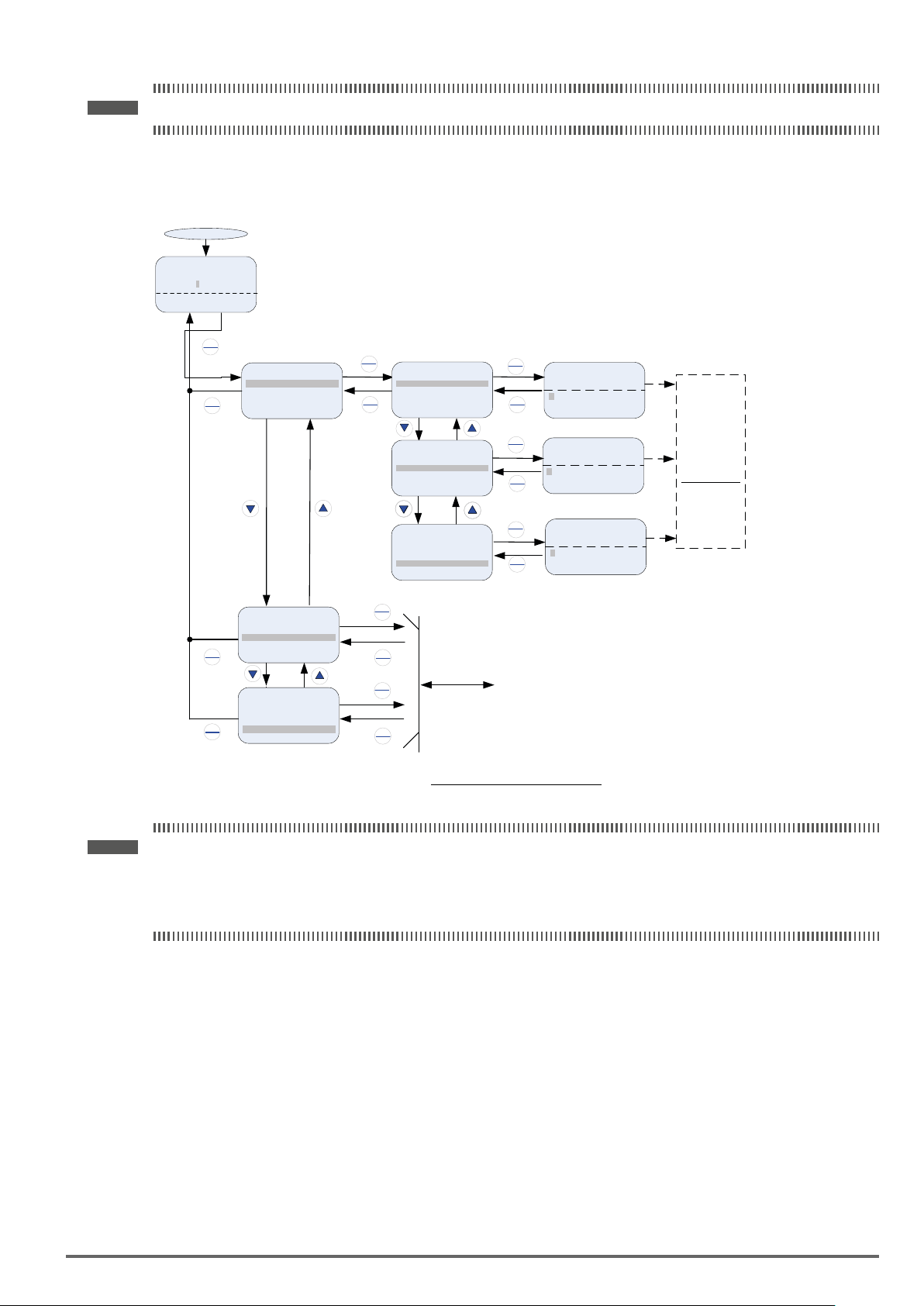
Note ! To scroll through the available monitor parameter list, press and hold the ▲(up) or ▼ (down) key.
Programming Mode
In programming mode inverter parameters can be read or changed. See Fig 4.2.2.3 for keypad navigation.
Power ON
Monitor
Freq Ref
12-16=005.00Hz
12-17=000.00Hz
12-18=0000.0A
Parameter Group
DSP
FUN
Selection Mode
Group
00 Basic Func.
01 V/F Pattern
DSP
02 Motor Parameter
FUN
READ
ENTER
PARA 00
-00 Control Method
-01 Motor Direction
-02 Run Source
DSP
FUN
PARA 00
-00 Control Method
-01 Motor Direction
-02 Run Source
PARA 00
-00 Control Method
-01 Motor Direction
-02 Run Source
Parameter
Group Mode
READ
ENTER
READ
ENTER
READ
ENTER
DSP
FUN
DSP
FUN
DSP
FUN
Parameter
Edit Mode
Edit 00-00
Control Method
0 V/F
(0~4)
<0>
Edit 00-01
Motor Direction
0 Forward
(0~1)
<0>
Edit 00-02
Run Source
0 Digital Op
(0~4)
<1>
Press ▼ or ▲
READ/ENTER
key to edit
parameter
value, and
press
key to save
the change.
READ
Group
00 Basic Fun.
01 V/F Pattern
02 Motor Parameter
DSP
FUN
Group
00 Basic Fun.
01 V/F Pattern
DSP
02 Motor Parameter
FUN
ENTER
DSP
FUN
READ
ENTER
DSP
FUN
To parameters
Fig4.2.2.3ProgrammingMode
Note ! - The parameters values can be changed from the Edit screen with the up, down and < / RESET shift key.
- To save a parameter press the READ/ENTER key.
- Refer to section 4.4 for parameter details.
- Press the▲(up) or (down) key to scroll parameter groups or parameter list.
VDI100 • Instruction manual 53
Page 54
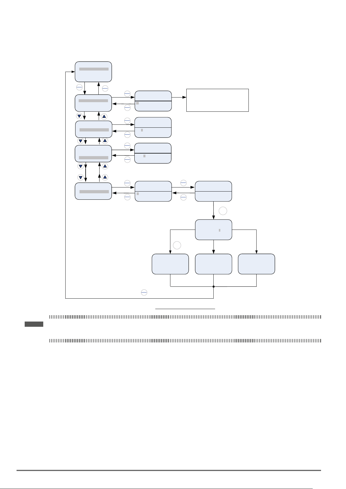
Auto-tuning Mode
In the auto-tuning mode motor parameters can be calculated and set automatically based on the selected control mode. See Fig 4.2.2.4 for keypad navigation.
Group
17 Auto-tuning
18 Slip Compen
19 Traverse Func.
READ
ENTER
PARA 17
-01 Tune Mode Sel
-02 Motor Rated Power
-03 Motor Rated Curr.
PARA 17
-01 Tune Mode Sel
-02 Motor Rated Power
-03 Motor Rated Curr.
PARA 17
-01 Tune Mode Sel
-02 Motor Rated Power
-03 Motor Rated Curr.
PARA 17
-08 Mtr No-Load Volt
-10 Auto-tuning Run
-11 Auto-tuning Err
DSP
FUN
READ
Edit 17-00
ENTER
Tune Mo de Sel
0 Rotational
(0 ~ 2)
DSP
FUN
< 0 >
READ
Edit 17-01
ENTER
Motor Ra ted Power
5.50 KW
(0.00 – 600.00)
DSP
FUN
< 5.50>
READ
Edit 17-02
ENTER
READ
ENTER
Motor Sel
0006.8 A
DSP
(0000.9~0009.2)
FUN
< 0006.8 >
Edit 17-10
Auto-tun ing Run
1 Enable
DSP
(0~1)
FUN
<0>
Edit
Autotuning
>>>>>>>>>>>>>>>
0.0Hz – 0.0A
Aborted
Press ▲ or ▼ key to change the value.
Warning: Do not use “0”, Rotati on
Auto-tune, when l oad is coupled with
the motor.
*1HP = 0.746KW
READ
Edit
ENTER
Autotuning ?
000.00Hz-000.0A
DSP
FUN
(Press Run Key)
Edit
Autotuning
>>>>>>>>>>>>>>>
48.0Hz – 14.0A
(Rotational)
STOP
Edit Edit
Autotuning
>>>>>>>>>>>>>>>>>>>>>>>
48.0Hz – 14.0A
Successful
RUN
Tuning
successful
ATE01
>>>>>>>>>>>>>>>
Motor Data Error
Uncompleted
Tuning
fault
DSP
FUN
Fig4.2.2.4Auto-tuningMode
Note ! - Set correct motor parameters by referring to motor nameplate.
- Refer to section 4.4 for parameter details.
4.2.3. Notes
1. Use the up and down keys to scroll though the auto-tuning parameter list. Depending on the selected control mode in parameter 00-00, part of auto-tuning parameters will not be accessible. (Refer to the Auto-tuning Group 17 parameters).
2. After entering the motor nameplate rated output power (17-01), rated current (17-02), rated voltage (17-
03), rated frequency (17-04), rated speed (17-05) and number of motor poles (17-06), select the automatic
tuning mode and press the RUN key to perform the auto-tuning operation. When auto-tuning is successful
the calculated motor parameters will be saved into parameter group 02 (motor parameter).
3. (a) “Rotational” will be displayed during rotational auto-tuning (17-00=0) and the motor will rotate during
auto-tuning. Ensure that it is safe to operate the motor before pressing the RUN key.
(b) “Stationary” will be displayed during stationary auto-tuning (17-00=1), the motor shaft does not rotate.
(c) “R1 Tuning” will be displayed during stationary auto-tuning (17-00=2), the motor shaft does not rotate.
54 VDI100 • Instruction manual
Page 55

(d) The RUN LED (in the upper left corner of the RUN key) will be lit during auto-tuning.
(e) The LCD display shows “>>>” or “Atund” during the auto-tuning process.
4. Press the STOP key on the keypad to abort the auto-tuning operation.
5. In case of an auto-tuning fault, a fault message and the uncompleted message are displayed on the
keypad. The RUN LED will be ashing and the motor will coast to stop. (Refer to section 10.4 for the Auto-tuning Faults.) The auto-tuning fault can be cleared by pressing the RESET key after which the keypad
displays the auto-tuning mode again.
All motor parameters (group 02 through group 17 parameters) will revert back to their factory settings if a
fault occurs. The motor data must be entered again before re-starting auto-tuning. The keypad shows “>>>”
during an auto-tuning fault.
6. Upon successful completion of an auto-tune, the RUN LED will turn off. Press the DSP/FUN key to return to
the main menu to select the next operation. The auto-tuning procedure takes approximately 50 seconds.
VDI100 • Instruction manual 55
Page 56
4.3. Parameters
Parameter group Group Name
Group 00 Basic Parameters
Group 01 V/f Control Parameters
Group 02 IM Motor Parameters
Group 03 External Digital Input and Output Parameters
Group 04 External Analog Input and Output Parameters
Group 05 Multi-Speed Parameters
Group 06 Automatic Program Operation Parameters
Group 07 Start /Stop Parameters
Group 08 Protection Parameters
Group 09 Communication Parameters
Group 10 PID Parameters
Group 11 Auxiliary Parameters
Group 12 Monitoring Parameters
Group 13 Maintenance Parameters
Group 14 PLC Parameters
Group 15 PLC Monitoring Parameters
Group 16 LCD Parameters
Group 17 Automatic Tuning Parameters
Group 18 Slip Compensation Parameters
Group 19 Wobble Frequency Parameters
Group 20 Speed Control Parameters
Group 21 Torque And Position Control Parameters
Group 22 PM Motor Parameters
Parameter Attribute
*1 Parameters can be changed during run operation.
*2 Reserved
*3 Parameter will not reset to default during a factory reset (initialization).
*4 Read-only parameter
*5 Parameter will be displayed in being coupled with the option card.
*6 Parameter will be displayed only in LED keypad.
*7 Parameter will be displayed only in LCD keypad.
Default
S Size (set value depending on the size of the device)
Control mode parameter setting:
O = settable
X = not settable
- = not applicable
56 VDI100 • Instruction manual
Page 57
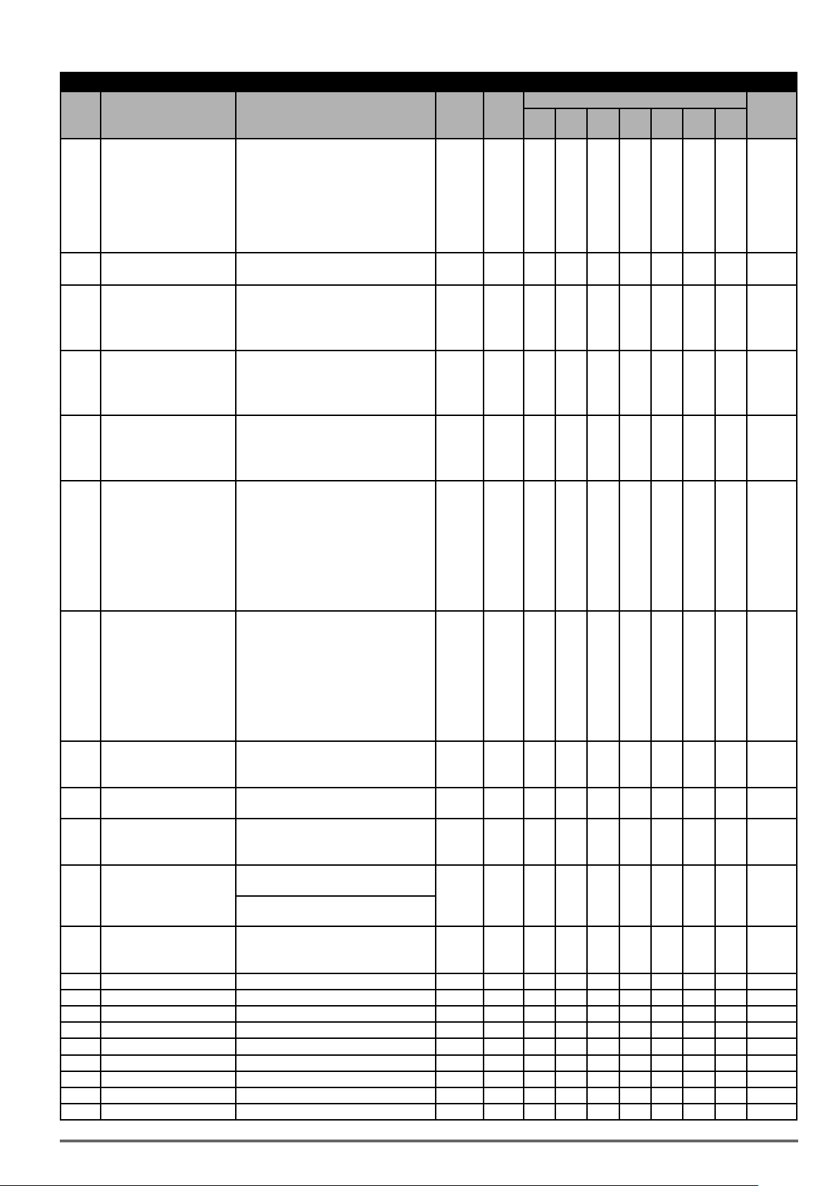
Group 00: Basic Parameters
Control mode
Code Parameter Name Setting Range Default Unit
0: V/f
1: V/f+PG
2: SLV
00-00 Control Mode Selection
00-01 Motor’s Rotation Direction
Main Run Command Source
00-02
Selection
Alternative Run Command
00-03
Selection
00-04 Language
Main Frequency Command
00-05
Source Selection
Alternative Frequency
00-06
Source Selection
Main and Alternative Fre-
00-07
quency Command Modes
Communication Frequency
00-08
Command Range
Communication Frequen-
00-09
cy Command Memory
Selection
Minimum frequency
00-10
detection
PID Lower Limit of Frequen-
00-11
cy Selection
00-12 Upper Frequency limit 0.1~109.0 100.0 % O O O O O O O
00-13 Lower Frequency limit 0.0~109.0 0.0 % O O O O O O O
00-14 Acceleration Time 1 0.1~6000.0 * s O O O O O O O *1
00-15 Deceleration Time 1 0.1~6000.0 * s O O O O O O O *1
00-16 Acceleration Time 2 0.1~6000.0 * s O O O O O O O *1
00-17 Deceleration Time 2 0.1~6000.0 * s O O O O O O O *1
00-18 *Jog Frequency 0.00~599.00 6.00 Hz O O O O O O O *1
00-19 Jog Acceleration Time 0.1~0600.0 - s O O O O O O O *1
00-20 Jog Deceleration Time 0.1~0600.0 - s O O O O O O O *1
3: SV
4: PMSV
5: PMSLV
6: SLV2
0: Forward
1: Reverse
0: Keypad
1: External Terminal (Control Circuit)
2: Communication Control (RS-485)
3: PLC
0: Keypad
1: External Terminal (Control Circuit)
2: Communication Control (RS-485)
3: PLC
0: English
1: Simplified Chinese
2: Traditional Chinese
3: Turkish
0: Keypad
1: External Terminal (Analog 1)
2: Terminal Command UP/DOWN
3: Communication Control (RS-485)
4: Pulse Input
5: Reserved
6: Reserved
7: AI2 Auxiliary Frequency
0: Keypad
1: External Terminal (Analog 1)
2: Terminal Command UP/DOWN
3: Communication Control (RS-485)
4: Pulse Input
5: Reserved
6: Reserved
7: AI2 Auxiliary Frequency
0: Main Frequency
1: Main frequency + Alternative Fre-
quency
0.00~599.00 0.00 Hz O O O O O O O
0: Don’t save when power supply is off.
(00-08)
1: Save when power is off. (00-08)
0:Show warning if lower than minimum
frequency
1:Run as minimum frequency if lower
than minimum frequency
0: PID Sleep Limit is Lower Limit of
Frequency
1: PID Sleep Limit is 0Hz
0 - O O O O O O O *3
0 - O O O O O O O *1
1 - O O O O O O O
2 - O O O O O O O
0 - O O O O O O O
1 - O O O O O O O
3 - O O O O O O O
0 - O O O O O O O
0 - O O O O O -
0 - O O O O O O O
0 - O O O O O O O
V/f
V/f
+PG
SLV SV
PM SVPM
SLV
SLV2
Attribute
VDI100 • Instruction manual 57
Page 58

Group 00: Basic Parameters
Control mode
Code Parameter Name Setting Range Default Unit
V/f
V/f
+PG
SLV SV
PM SVPM
SLV
00-21 Acceleration time 3 0.1~6000.0 * s O O O O O O O *1
00-22 Deceleration time 3 0.1~6000.0 * s O O O O O O O *1
00-23 Acceleration time 4 0.1~6000.0 * s O O O O O O O *1
00-24 Deceleration time 4 0.1~6000.0 * s O O O O O O O *1
Switch-Over Frequency of
00-25
Acc/Dec Time 1 and Time 4
0.00~599.00 0.0 Hz O O O O O O O
00-26 Emergency Stop Time 0.1~6000.0 5.0 s O O O O O O O
00-27 HD/ND Mode Selection ***
Command Characteris-
00-28
tic selection of master
frequency
0: HD (Heavy Duty Mode)
1: ND (Normal Duty Mode)
0: Positive Characteristic (0~10V/4~-
20mA is corresponding to 0~100%)
1: Negative Characteristic (0~10V/4~-
20mA is corresponding to 100~0%)
0 - O O X X X X X *3
0 - O O O O O O O
0: Operation Based on Frequency Command
Zero-Speed Operation
00-29
Selection
1: Stop
2: Operation Based on the Lowest
0 - X X X O O X X
Frequency
3: Zero-Speed Operation
00-30 Reserved
00-31 Reserved
0: General
1:
Reserved
2: Conveyor
Application Selection
00-32
Presets**
3: Exhaust Fan
4:
Reserved
0 - O O O O O O O
5: Compressor
6: Hoist**
7: Crane**
Modified Parameters (only
00-33
for LCD keypad)
0:Disable
1:Enable
0 - O O O O O O O *7
00-34
~
Reserved
00-40
00-41 User parameter 0
00-41 - O O O O O O O *7
00-42 User parameter 1 00-42 - O O O O O O O *7
00-43 User parameter 2 00-43 - O O O O O O O *7
00-44 User parameter 3 00-44 - O O O O O O O *7
00-45 User parameter 4 00-45 - O O O O O O O *7
00-46 User parameter 5 00-46 - O O O O O O O *7
Set 13-06 = 1, start user parameter. The
setting range is 01-00 ~24-06 (only for
LCD keypad)
00-47 User parameter 6 00-47 - O O O O O O O *7
00-48 User parameter 7 00-48 - O O O O O O O *7
00-49 User parameter 8
00-49 - O O O O O O O *7
00-50 User parameter 9 00-50 - O O O O O O O *7
00-51 User parameter 10 00-51 - O O O O O O O *7
00-52 User parameter 11 00-52 - O O O O O O O *7
00-53 User parameter 12 00-53 - O O O O O O O *7
00-54 User parameter13 00-54 - O O O O O O O *7
Set 13-06 = 1, start user parameter. The
setting range is 01-00 ~24-06. (only for
LCD keypad)
00-55 User parameter 14 00-55 - O O O O O O O *7
00-56 User parameter 15 00-56 - O O O O O O O *7
00-57 SV High Speed Mode
*: Refer to the following attachment 1.
**: Before to set up 00-32 Application, it should do initialized setting (parameter 13-08) first. When setting 00-32, the I/O port function changed automatically. To avoid accident,
be sure to confirm the I/O port signal of inverter and external terminal control.
*** If parameter 00-27 is set to ND mode, group 02 motor 1 parameter will automatically adjust to more than 1 class of it.
If parameter 00-27 is set to HD mode, group 02 motor 1 parameter will automatically adjust to the same class of it.
It is suggested that parameter 00-27 be set first before motor performs auto-tuning because the parameter will make the motor parameter automatically be changed.
***** If the maximum output frequency of motor is over 300HZ,the frequency resolution is changed to 0.1Hz
0: SV High Speed Mode1
1: SV High Speed Mode2
0 - X X X O
X X X
SLV2
Attribute
58 VDI100 • Instruction manual
Page 59

Group 01: V/f Control Parameters
Control mode
Code Parameter Name Setting Range Default Unit
01-00 V/f Curve Selection 0~FF F - O O X X X X O *3
01-01 Reserved
Maximum Output Frequen-
01-02
cy of Motor 1
Maximum Output Voltage of
01-03
Motor 1
Middle Output Frequency 2
01-04
of Motor 1
Middle Output Voltage 2 of
01-05
Motor 1
Middle Output Frequency 1
01-06
of Motor 1
Middle Output Voltage 1 of
01-07
Motor 1
5.0~599.0 60.0 Hz O O O O O O O
230V: 0.1~255.0
400V: 0.2~510.0
220.0 V O O X X X X O
0.0~599.0 0.0 Hz O O X X X X O
230V: 0.0~255.0
400V: 0.0~510.0
0.0 V O O X X X X O
0.0~599.0 3.0 Hz O O X X X X O
230V: 0.0~255.0
400V: 0.0~510.0
* V O O X X X X O
VF:1.5
VF+PG:
1.5
SLV: 0.6
Minimum Output Frequency
01-08
of Motor 1
0.0~599.0
SV:0.1
PM SV:0.1
PM
SLV:9.0
Hz O O O O O O O
SLV2:
1.0
Minimum Output Voltage of
01-09
Motor 1 (for
2.2~22kW)
230V: 0.0~255.0
7.5 V O O X X X X O
400V: 0.0~510.0
01-10 Torque Compensation Gain 0.0~2.0 0.5 - O O X X X X O *1
Selection of Torque Com-
01-11
pensation Mode
0: Torque Compensation Mode 0
1: Torque Compensation Mode 1
0 - O O X X X X X
01-12 Base Frequency of Motor 1 5.0~599.0 60.0 Hz O O O O O O O
Base Output Voltage of
01-13
Motor 1
01-14 Input Voltage Setting
230V: 0.0~255.0 220.0 V O O X X X X O
400V: 0.0~510.0 440.0
230V: 155.0~255.0 220.0
400V: 310.0~510.0 440.0
V O O O O O O O
01-15 Torque Compensation Time 1~10000 200 ms O O X X X X O
Maximum Output Frequen-
01-16
cy of Motor 2
Maximum Output Voltage of
01-17
Motor 2
Middle Output Frequency 2
01-18
of Motor 2
Middle Output Voltage 2 of
01-19
Motor 2
Middle Output Frequency 1
01-20
of Motor 2
Middle Output Voltage 1 of
01-21
Motor 2 (
Minimum Output Frequency
01-22
of Motor 2
Minimum Output Voltage of
01-23
Motor 2 (for
for 2.2~22kW)
for 2.2~22kW)
5.0~599.0 60.0 Hz O X X X X X X
200V: 0.1~255.0 220.0
400V: 0.2~510.0 440.0
V O X X X X X X
0.0~599.0 0.0 Hz O X X X X X X
230V: 0.0~255.0
400V: 0.0~510.0
0.0 V O X X X X X X
0.0~599.0 3.0 Hz O X X X X X X
230V: 0.0~255.0 14.0
V O X X X X X X
400V: 0.0~510.0 28.0
0.0~599.0 1.5 Hz O X X X X X X
230V: 0.0~255.0 7.5
V O X X X X X X
400V: 0.0~510.0 15.0
01-24 Base Frequency of Motor 2 5.0~599.0 60.0 Hz O X X X X X X
Base Output Voltage of
01-25
Motor 2
V/f Curve Selection of
01-26
Motor 2
*: Refer to the attachment 1.
230V: 0.0~255.0 220.0
400V: 0.0~510.0 440.0
V O X X X X X X
0~FF F - O X X X X X X *3
V/f
V/f
+PG
SLV SV
PM SVPM
SLV
SLV2
Attribute
VDI100 • Instruction manual 59
Page 60

Group 02: IM Motor Parameters
Control mode
Code Parameter Name Setting Range Default Unit
Control mode selection 0.01~600.00 - A O X X X X X O
02-00
Modes of V/f, V/f+PG are 10%~200% of
02-01 Rated Current of Motor1
02-02 Reserved
Rated Rotation Speed of
02-03
Motor1
02-04 Rated Voltage of Motor1
02-05 Rated Power of Motor1 0.01~600.00 - kW O O O O X X O
02-06 Rated Frequency of Motor1 5.0~599.0 60.0 Hz O O O O X X O
02-07 Poles of Motor 1 2~16(Even) 4 - O O O O X X O
02-08 Reserved
Excitation Current of Motor
02-09
1
Core Saturation Coefficient
02-10
1 of Motor 1
Core Saturation Coefficient
02-11
2 Motor 1
Core Saturation Coefficient
02-12
3 of Motor 1
02-13 Core loss of Motor 1 0.0~15.0 - % O O X X X X O
02-14 Reserved
Resistance between Wires
02-15
of Motor 1
02-16
02-17
Reserved
02-18
02-19 No-Load Voltage of Motor 1
02-20 No-Load Current of Motor 2 0.01~600.00 - A O X X X X X X
02-21 Rated Current of Motor 2 10%~200% of inverter’s rated current - A O X X X X X X
Rated Rotation Speed of
02-22
Motor 2
02-23 Rated Voltage of Motor 2
02-24 Rated Power of Motor 2 0.01~600.00 - kW O X X X X X X
02-25 Rated Frequency of Motor 2 5.0~599.0 60.0 Hz O X X X X X X
02-26 Poles of Motor 2 2~16 (Even) 4 - O X X X X X X
02-27
~
Reserved
02-31
Resistance between Wires
02-32
of Motor 2
Proportion of Motor Leak02-33
age Inductance
02-34 Motor Slip Frequency 0.10~20.00
02-35
~
Reserved
02-36
02-37 Motor Mechanical Loss 0.0~10.0 4.0 % X X X O O X X
inverter’s rated current. Modes of SLV,
SV are 25%~200% of inverter’s rated
current.
0~60000 - rpm O O O O X X O
230V: 50.0~240.0 220.0
400V: 100.0~480.0 440.0
15%~70% of Motor Rated Current - % X X O O X X X
1~100 - % X X O O X X X
1~100 - % X X O O X X X
80~300 - % X X O O X X X
0.001~60.000 - Ω O O O O X X O
230V: 50~240 400V: 100~480 -
0~60000 - rpm O X X X X X X
230V: 50.0~240.0 220.0
400V: 100.0~480.0 440.0
0.001~60.000 - Ω O X X X X X X
0.1~15.0
- A O O O O X X O
V O O O O X X O
V X X O O X X X
V O X X X X X X
S % X X O O X X X
1.78 Hz X X O O X X X
V/f
V/f
+PG
SLV SV
PM SVPM
SLV
SLV2
Attribute
60 VDI100 • Instruction manual
Page 61

Group 03: External Digital Input and Output Parameters
Code Parameter Name Setting Range Default Unit
0: 2-Wire Sequence (ON: Forward Run
Command).
1: 2-Wire Sequence (ON: Reverse Run
Multi-Function
03-00
Terminal
Function Setting-S1
Multi-Function
03-01
Terminal
Function Setting-S2
Multi-Function
03-02
Terminal
Function Setting-S3
Multi-Function
03-03
Terminal
Function Setting-S4
Multi-Function
03-04
Terminal
Function Setting-S5
Multi-Function
03-05
Terminal
Function Setting-S6
Multi-Function
03-06
Terminal
Function Setting-S7
Command).
2: Multi-Speed/Position Setting Command 1 O O O O O O O
3: Multi-Speed/Position Setting Command 2 O O O O O O O
4: Multi-Speed/Position Setting Command 3 O O O O O O O
5: Multi-Speed/Position Setting Command 4 O O O O O O O
6: Forward Jog Run Command O O O O O O O
7: Reverse Jog Run Command
8: UP Frequency Increasing Command O O O O O O O
9: DOWN Frequency Decreasing Command O O O O O O O
10: Acceleration/Deceleration Time Selection 1
11: Inhibit Acceleration/ Deceleration Command
12: Main/ Alternative Run Switch Function O O O O O O O
13: Main/ Alternative Frequency Switch
Function
14: Emergency Stop (decelerate to zero and
stop)
15: External Baseblock Command (rotation
freely to stop)
16: PID Control Disable O O O O O O O
17: Fault Reset (RESET) O O O O O O O
18: Reserved - - - - - - 19: Speed Search 1 (from the maximum
frequency)
20: Manual Energy Saving Function O O X X X X X
21: PID Integral Reset
22~23 : Reserved - - - - - - 24: PLC Input O O O O O O O
25: External Fault O O O O O O O
26: 3-Wire Sequence (Forward/Reverse
command).
27: Local/ Remote Selection O O O O O O O
28: Remote Mode Selection
29: Jog Frequency Selection O O O O O O O
30: Acceleration/ Deceleration Time Selection 2
31: Inverter Overheating Warning O O O O O O O
32: Sync Command O O O O O O O
33: DC Braking O O O O X X O
34: Speed Search 2 (from the frequency
command)
35: Timing Function Input O O O O O O O
36: PID Soft Start Disable O O O O O O O
37: Traversing Operation
38: Upper Deviation of Traverse Operation O O X X X X O
39: Lower Deviation of Traverse Operation O O X X X X O
40: Switching between Motor 1/Motor 2 O O X X X X O
41: PID Sleep - - - - - - 42: PG Disable X O X X X X X
43: PG Integral Reset
44: Mode Switching between Speed and
Torque
45: Negative Torque Command X X X O O X X
46: Zero-Servo Command X X X O O X X
47: Fire mode(Forced Operation mode) O O O O O O O
48: KEB Acceleration O O X X X X O
49: Parameters Writing Allowable O O O O O O O
50: Unattended Start Protection (USP) O O O O O O O
0 -
1 -
2 -
3 -
4
17 -
29*
(26)*
Control mode
V/f
V/f
O O O O O O O
O O O O O O O
O O O O O O O
O O O O O O O
O O O O O O O
O O O O O O O
O O O O O O O
O O O O O O O
O O O O O X O
O O O O O O O
O O O O O O O
O O O O O O O
O O O O O O O
O O O O O X O
O O X X X X O
X O X O O X X
X X X O O X X
-
+PG
SLV SV
PM SVPM
SLV
SLV2
Attribute
VDI100 • Instruction manual 61
Page 62

Group 03: External Digital Input and Output Parameters
Control mode
Code Parameter Name Setting Range Default Unit
51: Mode Switching between Speed and
Position
52: Multi Position Reference Enable X X X O O X X
53: 2-Wire Self Holding Mode (Stop Command)
54: Reserved - - - - - - -
55: Reserved - - - - - - -
Multi-Function
03-07
Terminal
Function Setting-S8
03-08 (S1~S8) DI Scan Time
Multi-Function Terminal S103-09
S4 Type Selection
Multi-Function Terminal S503-10
S8 Type Selection
03-11 Relay (R1A-R1C) Output 0: During Running 0 - O O O O O O O
03-12 Relay (R2A-R2C) Output 20: Zero Speed 1 - O O O O O O O
56: Reserved - - - - - - 57: Reserved - - - - - - 58: Digital Input Stop Command O O O O O O O
59: Reserved - - - - - - 60: Reserved - - - - - - 61: Reserved - - - - - - 62: EPS Function O O O O O O O
63: Reserved - - - - - - 64: Reserved - - - - - - 65: Short-circuit braking X X X X X O X
0: Scan Time 4ms
1: Scan Time 8ms
xxx0b: S1 A Contact
xxx1b: S1 B Contact
xx0xb: S2 A Contact
xx1xb: S2 B Contact
x0xxb: S3 A Contact
x1xxb: S3 B Contact
0xxxb: S4 A Contact
1xxxb: S4 B Contact
xxx0b: S5 A Contact
xxx1b: S5 B Contact
xx0xb: S6 A Contact
xx1xb: S6 B Contact
x0xxb: S7 A Contact
x1xxb: S7 B Contact
0xxxb: S8 A Contact
1xxxb: S8 B Contact
1: Fault Contact Output O O O O O O O
2: Frequency Agree O O O O O O O
3: Setting Frequency Agree O O O O O O O
4: Frequency Detection 1 (> 03-13+03-14) O O O O O O O
5: Frequency Detection 2 (< 03-13+03-14) O O O O O O O
6: Automatic Restart O O O O O O O
7: Reserved - - - - - - 8: Reserved - - - - - - 9: Baseblock O O O O O O O
10: Reserved - - - - - - 11: Reserved - - - - - - 12: Over-Torque Detection O O O O O O O
13: Current Agree O O O O O O O
14: Mechanical Braking Control (03-17~18) O O O O O O O
15: Reserved - - - - - - 16: Reserved - - - - - - 17: Reserved - - - - - - 18: PLC status O O O O O O O
19: PLC Control Contact O O O O O O O
21: Inverter Ready O O O O O O O
22: Under Voltage Detection O O O O O O O
23: Source of Operation Command O O O O O O
24: Source of Frequency Command O O O O O O O
25: Low Torque Detection O O O O O O O
26: Frequency Reference Missing O O O O O O O
27: Timing Function Output O O O O O O O
28: Traverse Operation UP Status O O X X X X O
15 -
1 - O O O O O O O
0000b - O O O O O O O
0000b - O O O O O O O
V/f
V/f
X X X O O X X
O O O O O O O
+PG
SLV SV
PM SVPM
SLV
SLV2
Attribute
O
62 VDI100 • Instruction manual
Page 63

Group 03: External Digital Input and Output Parameters
Control mode
Code Parameter Name Setting Range Default Unit
29 : During Traverse Operation Status O O X X X X O
30 : Motor 2 Selection O O O O O O O
31: Zero Speed Servo Status (Position Mode) X X X O O X X
32: Communication Control Contacts O O O O O O O
33: Reserved - - - - - - 34: Reserved - - - - - - 35: Reserved - - - - - - 36: Reserved - - - - - - 37: PID Feedback Loss Detection Output O O O O O O O
38: Brake Release X X O O O X X
39: Frequency Detection 1 (dedicated for
Crane)
40: Frequency Output O O O O O X X
41: Position Agree (Position Mode) O O O O O X X
42: Reserved - - - - - - 43: Reserved - - - - - - 44: Reserved - - - - - - 45: PID sleep O O O O O O O
46: Reserved - - - - - - 47: Reserved - - - - - - 48: Reserved - - - - - - 49: Reserved - - - - - - 50: Frequency Detection 3 (> 03-44+03-45) O O O O O O O
51: Frequency Detection 4 (< 03-44+03-45) O O O O O O O
52: Frequency Detection 5 (> 03-46+03-47) O O O O O O O
53: Frequency Detection 6 (< 03-46+03-47) O O O O O O O
54: Turn on short-circuit braking X X X X X O X
03-13 Frequency Detection Level 0.0~599.0 0.0 Hz O O O O O O O
03-14 Frequency Detection Width 0.1~25.5 2.0 Hz O O O O O O O
03-15 Current Agree Level 0.1~999.9 0.1 A O O O O O O O
Delay Time of Current Agree
03-16
Detection
**Mechanical Braking Rele-
03-17
ase Level
**Mechanical Braking Level
03-18
Set
03-19 Relay (R1A-R2A) Type
03-20 Reserved
03-21 Reserved
03-22 Reserved
03-23 Reserved
03-24 Reserved
03-25 Reserved
03-26 Reserved
UP/DOWN Frequency Hold/
03-27
Adjust Selection
03-28 Photo-coupler Output
Photo-coupler Output
03-29
Selection
03-30 Selection of Pulse Input
03-31 Scale of Pulse Input
03-32 Pulse Input Gain 0.0~1000.0 100 % O O O O O O O *1
0.1~10.0 0.1 s O O O O O O O
0.00~599.00 0.00 Hz O O O O O O O
0.00~599.00 0.00 Hz O O O O O O O
xxx0b: R1 A Contact
xxx1b: R1 B Contact
xx0xb: R2 A Contact
(DO2 for F1)
xx1xb: R2 C Contact
0: Hold last set frequency when stopped 0 - O O O O O O O
1: Set frequency to 0 when stopped
2: Allow speed changes from last set frequen-
cy when stopped
3: Refresh frequency at acceleration.
Range and definition are the same as those of
03-11, 03-12
xxx0b: Photo-coupler A Contact
xxx1b: Photo-coupler B Contact
0: General Pulse Input
1: PWM
Depending on the setting of 03-30
03-30 = 0: 50~32000Hz
03-30 = 1:10~1000Hz
0000b - O O O O O O O
0 - O O O O O O O
0000b - O O O O O O O
0 - O O O O O O O
1000 Hz O O
V/f
V/f
O O O X X X X
SLV SV
+PG
O O O O O *1
PM SVPM
SLV
SLV2
Attribute
VDI100 • Instruction manual 63
Page 64

Group 03: External Digital Input and Output Parameters
Control mode
Code Parameter Name Setting Range Default Unit
03-33 Pulse Input Bias -100.0~100.0 0.0 % O O O O O O O *1
03-34 Filter Time of Pulse Input 0.00~2.00 0.1 s O O O O O O O *1
Function Setting of Pulse
03-35
Output
03-36 Scale of Pulse Output 1~32000 1000 Hz O O O O O O O *1
03-37 Timer ON Delay (DIO) 0.0~6000.0 0.0 s O O O O O O O
03-38 Timer OFF Delay (DIO) 0.0~6000.0 0.0 s O O O O O O O
03-39 Reserved
Up/Down Frequency Width
03-40
Setting
03-41 Torque Detection Level 0~300 10 % X X O O O X X
03-42 Brake Release Delay Time 0.00~65.00 0.00 s X X O O O X X
UP/DOWN Acceleration/
03-43
Deceleration Selection
03-44 Frequency Detection Level 2 0.0~599.0 0.0 Hz O O O O O O O
03-45 Frequency Detection Width 2 0.1~25.5 2.0 Hz O O O O O O O
03-46 Frequency Detection Level 3 0.0~599.0 0.0 Hz O O O O O O O
03-47 Frequency Detection Width 3 0.1~25.5 2.0 Hz O O O O O O O
1: Frequency Command 2 - O O O O O O O *1
2: Output Frequency
3: Output Frequency after Soft-Start
4: Motor Speed
5: PID Feedback
6: PID Input
7: PG Output (with PG card)
0.00~5.00 0.00 Hz O O O O O O O
0: Acceleration/ Deceleration Time 1
0 - O O O O O O O
1: Acceleration/ Deceleration Time 2
V/f
V/f
+PG
SLV SV
PM SVPM
SLV
SLV2
Attribute
* 2-wire operation mode: 29; 3-wire operation mode: 26.
* *If the maximum output frequency of motor is over 300HZ,the frequency resolution is changed to 0.1Hz
Group 04: External Analog Input and Output Parameters
Control mode
Code Parameter Name Setting Range Default Unit
0: AI1:0~10V
AI2: 0~10V / 0~20mA
1: AI1:0~10V
04-00 AI Input Signal Type
AI1 Signal Scanning and
04-01
Filtering Time
04-02 AI1 Gain 0.0~1000.0 100.0 % O O O O O O O *1
04-03 AI1 Bias -100.0~100.0 0 % O O O O O O O *1
04-04 Reserved
04-05 AI2 Function Setting 0: Auxiliary Frequency 0 - O O O O O O O
AI2: 4~20mA/ 2~10V
2: AI1: -10~10V
AI2: 0~10V/ 0~20mA
3: AI1: -10~10V
AI2: 4~20mA/ 2~10V
0.00~2.00 0.03 s O O O O O O O
1: Frequency Reference Gain O O O O O O O
2: Frequency Reference Bias O O O O O O O
3: Output Voltage Bias O O X X O O O
4: Coefficient of Acceleration and Decele-
ration Reduction
5: DC Braking Current O O O O X X O
6: Over-Torque Detection Level O O O O O O O
7: Stall Prevention Level During Running O O X X X X O
8: Frequency Lower Limit O O O O O O O
9: Jump Frequency 4 O O O O O O O
10: Added to AI1 O O O O O O O
11: Positive torque limit X X O O O O X
12: Negative torque limit X X O O O O X
13: Regenerative Torque Limit X X O O O O X
1 - O O O O O O O
V/f
V/f
O O O O O O O
+PG
SLV SV
PM SVPM
SLV
SLV2
Attribute
64 VDI100 • Instruction manual
Page 65
Group 04: External Analog Input and Output Parameters
Control mode
Code Parameter Name Setting Range Default Unit
14: Positive / Negative Torque Limit X X O O O O X
15: Torque Reference/ Torque Limit (in
Speed Control)
16: Torque Compensation X X O O O X X
17: PTC Overheat Protection O O O O O O O
AI2 Signal Scanning and
04-06
Filtering Time
04-07 AI2 Gain 0.0~1000.0 100.0 % O O O O O O O *1
04-08 AI2 Bias -100.0~100.0 0 % O O O O O O O *1
04-09
~
Reserved
04-10
04-11 AO1 Function Setting 0: Output Frequency 0 - O O O O O O O
04-12 AO1 Gain 0.0~1000.0 100.0 % O O O O O O O *1
04-13 AO1 Bias -100.0~100.0 0 % O O O O O O O *1
04-14 Reserved
04-15 Reserved
04-16 AO2 Function Setting
04-17 AO2 Gain 0.0~1000.0 100.0 % O O O O O O O *1
04-18 AO2 Bias -100.0~100.0 0 % O O O O O - *1
AO2 Output Signal Type
04-19
Filter Time of AO Signal
04-20
Scan
0.00~2.00 0.03 s O O O O O O O
1: Frequency Command O O O O O O O
2: Output Voltage O O O O O O O
3: DC Voltage O O O O O O O
4: Output Current O O O O O O O
5: Output Power O O O O O O O
6: Motor Speed O O O O O O O
7: Output Power Factor O O O O O O O
8: AI1 Input O O O O O O O
9: AI2 Input O O O O O O O
10: Torque Command X X O O O O X
11: q-axis Current X X O O O O X
12: d-axis Current X X O O O O X
13: Speed Deviation X X X O O X X
14: Reserved - - - - - - 15: ASR Output X O X O O X X
16: Reserved - - - - - - 17: q-axis Voltage X X O O O O X
18: d-axis Voltage X X O O O O X
19: Reserved - - - - - - 20: Reserved - - - - - - 21: PID Input O O O O O O O
22: PID Output O O O O O O O
23: PID Target Value O O O O O O O
24: PID Feedback Value O O O O O O O
25: Output Frequency of the Soft Starter O O O O O O O
26: PG Feedback X O X O O X X
27: Reserved - - - - - - 28: Communication control O O O O O O O
Range and definition are the same as
those of 04-11.
0: AO2 0~10V
1: AO2 4~20mA
0.00~0.50 0.00 s O O O O O O O *1
3 - O O O O O O O
0 - O O O O O O O
V/f
V/f
X X X O O X X
+PG
SLV SV
PM SVPM
SLV
SLV2
Attribute
VDI100 • Instruction manual 65
Page 66

Group 05: Multi-Speed Parameters
Code Parameter Name Setting Range Default Unit
Acceleration and Decelera-
05-00
tion Selection of Multi-Speed
*Frequency Setting of
05-01
Speed-Stage 0
*Frequency Setting of
05-02
Speed-Stage 1
*Frequency Setting of
05-03
Speed-Stage 2
*Frequency Setting of
05-04
Speed-Stage 3
*Frequency Setting of
05-05
Speed-Stage 4
*Frequency Setting of
05-06
Speed-Stage 5
*Frequency Setting of
05-07
Speed-Stage 6
*Frequency Setting of
05-08
Speed-Stage 7
*Frequency Setting of
05-09
Speed-Stage 8
*Frequency Setting of
05-10
Speed-Stage 9
*Frequency Setting of
05-11
Speed-Stage 10
*Frequency Setting of
05-12
Speed-Stage 11
*Frequency Setting of
05-13
Speed-Stage 12
*Frequency Setting of
05-14
Speed-Stage 13
*Frequency Setting of
05-15
Speed-Stage 14
*Frequency Setting of
05-16
Speed-Stage 15
Acceleration Time Setting
05-17
of Multi Speed 0
Deceleration Time Setting
05-18
of Multi Speed 0
Acceleration Time Setting
05-19
of Multi Speed 1
Deceleration Time Setting
05-20
of Multi Speed 1
Acceleration Time Setting
05-21
of Multi Speed 2
Deceleration Time Setting
05-22
of Multi Speed 2
Acceleration Time Setting
05-23
of Multi Speed 3
Deceleration Time Setting
05-24
of Multi Speed 3
Acceleration Time Setting
05-25
of Multi Speed 4
Deceleration Time Setting
05-26
of Multi Speed 4
Acceleration Time Setting
05-27
of Multi Speed 5
Deceleration Time Setting
05-28
of Multi Speed 5
Acceleration Time Setting
05-29
of Multi Speed 6
0: Acceleration and deceleration time are
set by 00-14 ~ 00-24
1: Acceleration and Deceleration Time are
set by 05-17 ~ 05-48
0.00~599.00 5.00 Hz O O O O O O O *1
0.00~599.00 5.00 Hz O O O O O O O *1
0.00~599.00 10.00 Hz O O O O O O O *1
0.00~599.00 20.00 Hz O O O O O O O *1
0.00~599.00 30.00 Hz O O O O O O O *1
0.00~599.00 40.00 Hz O O O O O O O *1
0.00~599.00 50.00 Hz O O O O O O O *1
0.00~599.00 50.00 Hz O O O O O O O *1
0.00~599.00 5.00 Hz O O O O O O O *1
0.00~599.00 5.00 Hz O O O O O O O *1
0.00~599.00 5.00 Hz O O O O O O O *1
0.00~599.00 5.00 Hz O O O O O O O *1
0.00~599.00 5.00 Hz O O O O O O O *1
0.00~599.00 5.00 Hz O O O O O O O *1
0.00~599.00 5.00 Hz O O O O O O O *1
0.00~599.00 5.00 Hz O O O O O O O *1
0.1~6000.0 10.0 s O O O O O O O
0.1~6000.0 10.0 s O O O O O O O
0.1~6000.0 10.0 s O O O O O O O
0.1~6000.0 10.0 s O O O O O O O
0.1~6000.0 10.0 s O O O O O O O
0.1~6000.0 10.0 s O O O O O O O
0.1~6000.0 10.0 s O O O O O O O
0.1~6000.0 10.0 s O O O O O O O
0.1~6000.0 10.0 s O O O O O O O
0.1~6000.0 10.0 s O O O O O O O
0.1~6000.0 10.0 s O O O
0.1~6000.0 10.0 s O O O O O O O
0.1~6000.0 10.0 s O O O O O O O
0 - O O O O O O O
V/f
V/f
+PG
Control mode
SLV SV
O O O O
PM SVPM
SLV
SLV2
Attribute
66 VDI100 • Instruction manual
Page 67

Group 05: Multi-Speed Parameters
Code Parameter Name Setting Range Default Unit
Deceleration Time Setting
05-30
of Multi Speed 6
Acceleration Time Setting
05-31
of Multi Speed 7
Deceleration Time Setting
05-32
of Multi Speed 7
Acceleration Time Setting
05-33
of Multi Speed 8
Deceleration Time Setting
05-34
of Multi Speed 8
Acceleration Time Setting
05-35
of Multi Speed 9
Deceleration Time Setting
05-36
of Multi Speed 9
Acceleration Time Setting
05-37
of Multi Speed 10
Deceleration Time Setting
05-38
of Multi Speed 10
Acceleration Time Setting
05-39
of Multi Speed 11
Deceleration Time Setting
05-40
of Multi Speed 11
Acceleration Time Setting
05-41
of Multi Speed 12
Deceleration Time Setting
05-42
of Multi Speed 12
Acceleration Time Setting
05-43
of Multi Speed 13
Deceleration Time Setting
05-44
of Multi Speed 13
Acceleration Time Setting
05-45
of Multi Speed 14
Deceleration Time Setting
05-46
of Multi Speed 14
Acceleration Time Setting
05-47
of Multi Speed 15
Deceleration Time Setting
05-48
of Multi Speed 15
* If the maximum output frequency of motor is over 300HZ, the frequency resolution is changed to 0.1Hz
0.1~6000.0 10.0 s O O O O O O O
0.1~6000.0 10.0 s O O O O O O O
0.1~6000.0 10.0 s O O O O O O O
0.1~6000.0 10.0 s O O O O O O O
0.1~6000.0 10.0 s O O O O O O O
0.1~6000.0 10.0 s O O O O O O O
0.1~6000.0 10.0 s O O O O O O O
0.1~6000.0 10.0 s O O O O O O O
0.1~6000.0 10.0 s O O O O O O O
0.1~6000.0 10.0 s O O O O O O O
0.1~6000.0 10.0 s O O O O O O O
0.1~6000.0 10.0 s O O O O O O O
0.1~6000.0 10.0 s O O O O O O O
0.1~6000.0 10.0 s O O O O O O O
0.1~6000.0 10.0 s O O O O O O O
0.1~6000.0 10.0 s O O O O O O O
0.1~6000.0 10.0 s O O O O O O O
0.1~6000.0 10.0 s O O O O O O O
0.1~6000.0 10.0 s O O O O O O O
V/f
V/f
+PG
Control mode
SLV SV
PM SVPM
SLV
SLV2
Attribute
Group 06: Automatic Program Operation Parameters
Control mode
Code Parameter Name Setting Range Default Unit
Auto Run (sequencer) mode
06-00
selection
VDI100 • Instruction manual 67
0: Disabled 0 - O O O X X X O
1: Execute a single cycle operation mode.
Restart speed is based on the previous
stopped speed.
2: Execute continuous cycle operation.
Restart speed is based on the previous
stopped speed.
3: After the completion of a single cycle,
the on-going operation speed is based on
the speed of the last stage. Restart speed
is based on the previous stopped speed.
4: Execute a single cycle operation.
Restart speed is based on the Speed-Stage 0.
V/f
V/f
+PG
SLV SV
PM SVPM
SLV
SLV2
Attribute
Page 68
Group 06: Automatic Program Operation Parameters
Code Parameter Name Setting Range Default Unit
5: Execute continuous cycle operation.
Restart speed is based on the Speed-Stage 0.
6: After completion of a single cycle, the
on-going operation speed is based on the
speed of the last stage. Restart speed is
based on the Speed-Stage 0
*Frequency Setting of
06-01
Operation-Stage 1
*Frequency Setting of
06-02
Operation-Stage 2
*Frequency Setting of
06-03
Operation-Stage 3
*Frequency Setting of
06-04
Operation-Stage 4
*Frequency Setting of
06-05
Operation-Stage 5
*Frequency Setting of
06-06
Operation-Stage 6
*Frequency Setting of
06-07
Operation-Stage 7
*Frequency Setting of
06-08
Operation-Stage 8
*Frequency Setting of
06-09
Operation-Stage 9
*Frequency Setting of
06-10
Operation-Stage 10
*Frequency Setting of
06-11
Operation-Stage 11
*Frequency Setting of
06-12
Operation-Stage 12
*Frequency Setting of
06-13
Operation-Stage 13
*Frequency Setting of
06-14
Operation-Stage 14
*Frequency Setting of
06-15
Operation-Stage 15
Operation Time Setting of
06-16
Speed-Stage 0
Operation Time Setting of
06-17
Speed-Stage 1
Operation Time Setting of
06-18
Speed-Stage 2
Operation Time Setting of
06-19
Speed-Stage 3
Operation Time Setting of
06-20
Speed-Stage 4
Operation Time Setting of
06-21
Speed-Stage 5
Operation Time Setting of
06-22
Speed-Stage 6
Operation Time Setting of
06-23
Speed-Stage 7
Operation Time Setting of
06-24
Speed-Stage 8
Operation Time Setting of
06-25
Speed-Stage 9
Operation Time Setting of
06-26
Speed-Stage 10
Operation Time Setting of
06-27
Speed-Stage 11
0.00~599.00 5.00 Hz O O O X X X O *1
0.00~599.00 10.00 Hz O O O X X X O *1
0.00~599.00 20.00 Hz O O O X X X O *1
0.00~599.00 30.00 Hz O O O X X X O *1
0.00~599.00 40.00 Hz O O O X X X O *1
0.00~599.00 50.00 Hz O O O X X X O *1
0.00~599.00 50.00 Hz O O O X X X O *1
0.00~599.00 5.00 Hz O O O X X X O *1
0.00~599.00 5.00 Hz O O O X X X O *1
0.00~599.00 5.00 Hz O O O X X X O *1
0.00~599.00 5.00 Hz O O O X X X O *1
0.00~599.00 5.00 Hz O O O X X X O *1
0.00~599.00 5.00 Hz O O O X X X O *1
0.00~599.00 5.00 Hz O O O X X X O *1
0.00~599.00 5.00 Hz O O O X X X O *1
0.0~6000.0 0.0 s O O O X X X O *1
0.0~6000.0 0.0 s O O O X X X O *1
0.0~6000.0 0.0 s O O O X X X O *1
0.0~6000.0 0.0 s O O O X X X O *1
0.0~6000.0 0.0 s O O O X X X O *1
0.0~6000.0 0.0 s O O O X X X O *1
0.0~6000.0 0.0 s O O O X X X O *1
0.0~6000.0 0.0 s O O O X X X O *1
0.0~6000.0 0.0 s O O O X X X O *1
0.0~6000.0 0.0 s O O O X X X O *1
0.0~6000.0 0.0 s O O O X X X O *1
0.0~6000.0 0.0 s O O O X
V/f
V/f
+PG
Control mode
SLV SV
PM SVPM
SLV
X X O *1
SLV2
Attribute
68 VDI100 • Instruction manual
Page 69

Group 06: Automatic Program Operation Parameters
Code Parameter Name Setting Range Default Unit
Operation Time Setting of
06-28
Speed-Stage 12
Operation Time Setting of
06-29
Speed-Stage 13
Operation Time Setting of
06-30
Speed-Stage 14
Operation Time Setting of
06-31
Speed-Stage 15
Operation Direction Se06-32
lection of Speed-Stage 0
Operation Direction Se06-33
lection of Speed-Stage 1
Operation Direction Se06-34
lection of Speed-Stage 2
Operation Direction Se06-35
lection of Speed-Stage 3
Operation Direction Se06-36
lection of Speed-Stage 4
Operation Direction Se06-37
lection of Speed-Stage 5
Operation Direction Se06-38
lection of Speed-Stage 6
Operation Direction Se06-39
lection of Speed-Stage 7
Operation Direction Se06-40
lection of Speed-Stage 8
Operation Direction Se-
06-41
lection of Speed-Stage 9
Operation Direction Se-
06-42
lection of Speed-Stage 10
Operation Direction Se-
06-43
lection of Speed-Stage 11
Operation Direction Se-
06-44
lection of Speed-Stage 12
Operation Direction Se-
06-45
lection of Speed-Stage 13
Operation Direction Se-
06-46
lection of Speed-Stage 14
0.0~6000.0 0.0 s O O O X X X O *1
0.0~6000.0 0.0 s O O O X X X O *1
0.0~6000.0 0.0 s O O O X X X O *1
0.0~6000.0 0.0 s O O O X X X O *1
0: Stop
0 - O O O X X X O1: Forward
2: Reverse
0: Stop
0 - O O O X X X O1: Forward
2: Reverse
0: Stop
0 - O O O X X X O1: Forward
2: Reverse
0: Stop
0 - O O O X X X O1: Forward
2: Reverse
0: Stop
0 - O O O X X X O1: Forward
2: Reverse
0: Stop
0 - O O O X X X O1: Forward
2: Reverse
0: Stop
0 - O O O X X X O1: Forward
2: Reverse
0: Stop
0 - O O O X X X O1: Forward
2: Reverse
0: Stop
0 - O O O X X X O1: Forward
2: Reverse
0: Stop
0 - O O O X X X O1: Forward
2: Reverse
0: Stop
0 - O O O X X X O1: Forward
2: Reverse
0: Stop
0 - O O O X X X O1: Forward
2: Reverse
0: Stop
0 - O O O X X X O1: Forward
2: Reverse
0: Stop
0 - O O O X X X O1: Forward
2: Reverse
0: Stop
0 - O O O X X X O1: Forward
2: Reverse
V/f
V/f
+PG
Control mode
SLV SV
PM SVPM
SLV
SLV2
Attribute
VDI100 • Instruction manual 69
Page 70

Group 06: Automatic Program Operation Parameters
Control mode
Code Parameter Name Setting Range Default Unit
Operation Direction Se-
06-47
lection of Speed-Stage 15
* If the maximum output frequency of motor is over 300HZ,the frequency resolution is changed to 0.1Hz
0: Stop
0 - O O O X X X O1: Forward
2: Reverse
V/f
V/f
+PG
SLV SV
PM SVPM
SLV
Group 07: Start /Stop Parameters
Control mode
Code Parameter Name Setting Range Default Unit
Momentary Power Loss/
07-00
Fault Restart Selection
07-01 Fault Auto-Restart Time 0~7200 0 s O O O O O O O
Number of Fault Auto-Re-
07-02
start Attempts
07-03 Reserved
07-04 Direct Start at Power on
Delay of Direct Start at
07-05
Power on
DC Injection Braking Star-
07-06
ting Frequency
07-07 DC Injection Braking Current 0~100 50 % O O O
DC Injection Braking Time
07-08
at Stop
07-09 Stop Mode Selection 0: Deceleration to Stop 0 - O O O O X X O
07-10
~
Reserved
07-12
Low Voltage Detection
07-13
Level
07-14 Pre-excitation Time 0.00~10.00 2.00 s X X O X X X X
07-15 Pre-excitation Level 50~200 100 % X X O X X X X
DC Injection Braking Time
07-16
at Start
07-17 Reserved
07-18 Minimum Base block Time 0.1~5.0 - s O O O O X O O
Direction-Detection Speed
07-19
Search Operating Current
Speed Search Operating
07-20
Current
Integral Time of Speed
07-21
Searching
Delay Time of Speed
07-22
Searching
07-23 Voltage Recovery Time 0.1~5.0 2.0 s O O O X X X O
Direction-Detection Speed
07-24
Search Selection
07-25 Low Voltage Detection Time 0.00~1.00 0.02 s O O O O O O O
Start-up Mode Selection of
07-26
SLV Coast to Stop
Start Selection after Fault
07-27
during SLV Mode
Start after External Base
07-28
Block
0: Disable
1: Enable
0~10 0 - O O O O O O O
0: When the external run command is
enabled, direct start at power up
1: When the external run command is
enabled, unable to direct start at powerup.
1.0~300.0 3.5 s O O O O O O O
0.0~10.0 0.5 Hz O O O O
0.00~100.00 0.50 s O O O O
1: Coast to Stop
2: DC Braking Stop in All Fields
3: Coast to Stop with Timer
230V: 150~300 190
400V: 250~600 380
0.00~100.00 0.00 s O O O O
0~100 50 % O X O X X X O
0~100 20 % O X O X X X O
0.1~10.0 2.0 s O X O X X X O
0.0~20.0 0.2 s O O O O O X O
0: Disable
1: Enable
0: Start with speed search
1: Normal start
0: Start with speed search
1: Normal start
0: Start with speed search
1: Normal start
0 - O O O O X X O
1 - O O O O O O O
V O O O O O O O
1 - O O O X X X O
0 - X X O X X X X
0 - X X O X X X X
0 - O X O X X X O
V/f
V/f
+PG
SLV SV
X X X O
PM SVPM
SLV
O O O
O X O
O X O
SLV2
SLV2
Attribute
Attribute
70 VDI100 • Instruction manual
Page 71
Group 07: Start /Stop Parameters
Control mode
Code Parameter Name Setting Range Default Unit
Run Command Selection at
07-29
the Action of DC Braking
07-30 Low Voltage Level Selection
**Low Voltage Run Fre-
07-31
quency
Speed Search Mode
07-32
Selection
Start Frequency of Speed
07-33
Search Selection
Start short-circuit braking
07-34
time
Stop Short-circuit braking
07-35
time
Short-circuit braking current
07-36
limited
*07-13 Low Voltage Detection Level, it is enable when 07-30 Low Voltage Level Selection set 0 (Enable) and lower frequency limit set to 250V.This application is for Emergency
power supply (EPS)
* *If the maximum output frequency of motor is over 300HZ,the frequency resolution is changed to 0.1Hz
0: Not Allowable to Run
0 - O O X X X X X
1: Allowable to Run
0: Disable
1: Enable
0 -
0.00~599.00 10.00 Hz
0: Disable
1: Execute a Speed Search at Power On
0: Maximum Output Frequency of Motor
1: Frequency Command
0 - O O O O X X X
0 - O O O O X X X
0.00~100.00 0.00 s X X X X X O X
0.00~100.00 0.50 s X X X X X O X
0.0~200.0 100.0 % X X X X X O X
V/f
V/f
+PG
SLV SV
PM SVPM
SLV
O O O O O X O
O O O O O X O
SLV2
Attribute
Group 08: Protection Parameters
Control mode
Code Parameter Name Setting Range Default Unit
08-00 Stall Prevention Function
xxx0b: Stall prevention is enabled in
acceleration.
0000b - O O O O O O O
xxx1b: Stall prevention is disabled in
acceleration.
xx0xb: Stall prevention is enabled in
deceleration.
xx1xb: Stall prevention is disabled in
deceleration.
x0xxb: Stall prevention is enabled in
operation
x1xxb: Stall prevention is disabled in
operation
0xxxb: Stall prevention in operation is
based on deceleration time of speed-stage 1.
1xxxb: Stall prevention in operation is
based on deceleration time of speed-stage 2.
Stall Prevention Level in
08-01
Acceleration
Stall Prevention Level in
08-02
Deceleration
Stall Prevention Level in
08-03
Operation
20~200
230V: 330V~410V 385V
400V: 660V~820V 770V
30~200
HD:150
ND:120
HD:160
ND:120
08-04 Reserved
Selection for Motor Overlo-
08-05
ad Protection (OL1)
xxx0b: Overload Protection is disabled. 0001b - O O O O O O O
xxx1b: Overload Protection is enabled.
xx0xb: Cold Start of Motor Overload
xx1xb: Hot Start of Motor Overload
x0xxb: Standard Motor
x1xxb: Inverter Duty Motor
0xxxb: Reserved
1xxxb: Reserved
V/f
V/f
+PG
SLV SV
PM SVPM
SLV
% O O O X X O O
V O O O O X O O
% O O X X X X O
SLV2
Attribute
VDI100 • Instruction manual 71
Page 72
Group 08: Protection Parameters
Code Parameter Name Setting Range Default Unit
Start-up Mode of Overload
08-06
Protection Operation (OL1)
08-07 Reserved
Automatic Voltage Regula08-08
tion (AVR)
Selection of Input Phase
08-09
Loss Protection
Selection of Output Phase
08-10
Loss Protection
08-11
~
Reserved
08-12
Selection of Over-Torque
08-13
Detection
Selection of Over-Torque
08-14
Operation
Level of Over-Torque
08-15
Detection
Time of Over-Torque
08-16
Detection
Selection of Low-Torque
08-17
Detection
Selection of Low-Torque
08-18
Operation
Level of Low-Torque
08-19
Detection
Time of Low-Torque
08-20
Detection
Limit of Stall Prevention in
08-21
Acc over Base Speed
Stall Prevention Detection
08-22
Time in Operation
08-23 Ground Fault (GF) Selection
External Fault Operation
08-24
Selection
Detection Selection of
08-25
External Fault
0: Stop Output after Overload Protection
1: Continuous Operation after Overload
Protection.
0: Enable
1: Disable
0: Enable
1: Disable
0: Enable
1: Disable
0: Over-Torque Detection is Disabled. 0 - O O O O O O O
1: Start to Detect when Reaching the Set
Frequency.
2: Start to Detect when the Operation is
Begun.
0: Deceleration to Stop when Over Torque
is Detected.
1: Display Warning when Over Torque is
Detected. Go on Operation.
2: Coast to Stop when Over Torque is
Detected
0~300 150 % O O O O O O O
0.0~10.0 0.1 s O O O O O O O
0: Low-Torque Detection is Disabled. 0 - O O O O O O O
1: Start to Detect when Reaching the Set
Frequency.
2: Start to Detect when the Operation is
Begun.
0: Deceleration to Stop when Low Torque
is Detected.
1: Display Warning when Low Torque is
Detected. Go on Operation.
2: Coast to Stop when Low Torque is
Detected
0~300 30 % O O O O O O O
0.0~10.0 0.1 s O O O O O O O
1~100 50 % O O O X X O O
2~100 100 ms O O O X X O O
0: Disable
1: Enable
0: Deceleration to Stop 0 - O O O O O O O
1: Coast to Stop
2: Continuous Operation
0: Immediately Detect when the Power is
Supplied.
1: Start to Detect when the Operation is
Started.
0 - O O O O O O O
0 - O O O O O O O
0 - O O O O O O O
0 - O O O O O O O
0 - O O O O O O O
0 - O O O O O O O
0 - O O O O O O O
0 - O O O O O O O
V/f
V/f
+PG
Control mode
SLV SV
PM SVPM
SLV
SLV2
Attribute
72 VDI100 • Instruction manual
Page 73
Group 08: Protection Parameters
Control mode
Code Parameter Name Setting Range Default Unit
08-26
~
Reserved
08-29
Digital Input Stop Command
08-30
Selection
08-31
08-32
Reserved
08-33
08-34
Motor Overheat Fault
08-35
Selection
PTC Input Filter Time
08-36
Constant
08-37 Fan Control Function 0: Start in operation 0 O O O O O O O
08-38 Delay Time of Fan Off 0~600 60 s O O O O O O O
Delay Time of Motor
08-39
Overheat Protection
Motor2 Acceleration Stall
08-40
Prevention Level
Motor2 Acceleration Stall
08-41
Prevention Limit
08-42 PTC Protection Level 0~10.0V 0.3 V O O O O O O O
08-43 PTC Restart Level 0~10.0V 1.2 V O O O O O O O
08-44 PTC Warning Level 0~10.0V 0.6 V O O O O O O O
0: Deceleration to Stop
1: Coast to Stop
0: Disable 0 - O O O O O O O
1: Deceleration to Stop
2: Free Run to top
3: Continue Running
0.00 ~ 10.00
1: Permanent Start
2: Start in high temperature (except of the
models of
1~300 60 sec O O O O O O O
20~200
1~100 50 % O O O X X O O
6750 or the above)
0 - O O O O O O O
2 s O O O O O O O
HD:150
ND:120
% O O O X X O O
V/f
V/f
+PG
SLV SV
PM SVPM
SLV
SLV2
Attribute
Group 09: Communication Parameters
Control mode
Code Parameter Name Setting Range Default Unit
INV Communication Station
09-00
Address
Communication Mode
09-01
Selection
09-02 Baud Rate Setting (bps) 0: 1200 4 - O O O O O O O *2
09-03 Stop Bit Selection 0: 1 Stop Bit 0 - O O O O O O O *2
09-04 Parity Selection 0: No Parity 0 - O O O O O O O *2
Communication Data Bit
09-05
Selection
1~31 1 - O O O O O O O
0: MODBUS 0 O O O O O O O
1: Reserved
2: Reserved
3: Reserved
4: PROFIBUS*
1: 2400
2: 4800
3: 9600
4: 19200
5: 38400
1: 2 Stop Bit
1: Even Bit
2: Odd Bit
0: 8 Bit Data 0 - O O O O O O O *3
1: 7 Bit Data
V/f
V/f
+PG
SLV SV
PM SVPM
SLV
SLV2
Attribute
*3
*3
*5
VDI100 • Instruction manual 73
Page 74

Group 09: Communication Parameters
Control mode
Code Parameter Name Setting Range Default Unit
Communication Error
09-06
Detection Time
09-07 Fault Stop Selection
Comm. Fault Tolerance
09-08
Count
09-09 Waiting Time 5~65 5 ms O O O O O O O
09-10 Reserved
* Selection of item 4 in parameter 09-01 is required to be coupled with the Profibus card.
* Parameter 09 does not be influenced by 13-08 (Restore Factory Setting)
0.0~25.5 0.0 S O O O O O O O
0: Deceleration to Stop Based on Deceleration Time 1 when Communication Fault
Occurs.
1: Coast to Stop when Communication
Fault Occurs.
2: Deceleration to Stop Based on Deceleration Time 2 when Communication Fault
Occurs.
3: Keep Operating when Communication
Fault Occurs.
1~20 1 - O O O O O O O
3 - O O O O O O O
V/f
V/f
+PG
SLV SV
PM SVPM
SLV
SLV2
Attribute
Group 10: PID Parameters
Control mode
Code Parameter Name Setting Range Default Unit
PID Target Value Source
10-00
Setting
PID Feedback Value Source
10-01
Setting
10-02 PID Target Value 0.00~100.00 0.00 % O O O O O O O *1
10-03 PID Control Mode xxx0b: PID Disable 0000b - O O O O O O O
10-04 Feedback Gain 0.01~10.00 1.00 - O O O O O O O *1
10-05 Proportional Gain (P) 0.00~10.00 1.00 - O O O O O O O *1
10-06 Integral Time (I)
10-07 Differential Time (D) 0.00~10.00 0.00 s O O O O O O O *1
10-08 Reserved
10-09 PID Bias -100.0~100.0 0 % O O O O O O O *1
10-10 PID Output Delay Time 0.00~10.00 0.00 s O O O O O O O *1
PID Feedback Loss De10-11
tection Selection
10-12 PID Feedback Loss Det. Lev. 0~100 0 % O O O O O O O
1: AI1 given 1 - O O O O O O O
2: AI2 given
3: PI given
4:10-02 given
5: Reserved
6: Frequency Command (00-05)
1: AI1 given 2 - O O O O O O O
2: AI2 given
3: PI given
xxx1b: PID Enable
xx0xb: PID Positive Characteristic
xx1xb: PID Negative Characteristic
x0xxb: PID Error Value of D Control
x1xxb: PID Feedback Value of D Ctrl
0xxxb: PID Output
1xxxb: PID Output + Frequency Com-
mand
0.00~100.00 1.00 s O O O O O O O *1
0: Disable 0 - O O O O O O O
1: Warning
2: Fault
V/f
V/f
+PG
SLV SV
PM SVPM
SLV
SLV2
Attribute
74 VDI100 • Instruction manual
Page 75

Group 10: PID Parameters
Control mode
Code Parameter Name Setting Range Default Unit
PID Feedback Loss Det.
10-13
Time
10-14 PID Integral Limit 0.0~100.0 100.0 % O O O O O O O *1
10-15
~
Reserved
10-16
*Start Frequency of PID
10-17
Sleep
10-18 Delay Time of PID Sleep 0.0~255.5 0.0 s O O O O O O O
*Frequency of PID Waking
10-19
up
Delay Time of PID Waking
10-20
up
10-21
~
Reserved
10-22
PID Output Limit 0.00~100.0 100.0 % O O O O O O O *1
10-23
10-24 PID Output Gain 0.0~25.0 1.0 - O O O O O O O
PID Reversal Output
10-25
Selection
PID Target Acceleration/
10-26
Deceleration Time
10-27 PID Feedback Display Bias -99.99~99.99 0.00 - O O O O O O O
10-28 PID Feedback Display Gain 0.00~100.00 100.00 - O O O O O O O
10-29 PID Sleep Selection 0: Disable 1 - O O O O O O O
10-30 Upper Limit of PID Target 0.0 ~ 100.0 100.0 % O O O O O O O
10-31 Lower Limit of PID Target 0.0 ~ 100.0 0.0 % O O O O O O O
10-32 Reserved
Maximum Value of PID
10-33
Feedback
10-34 PID Decimal Width 0 ~ 4 1 O O O O O O O
10-35 PID Unit 0: % 0 O O O O O O O *7
0.0~10.0 1.0 s O O O O O O O
0.00~599.00 0.00 Hz O O O O O O O
0.00~599.00 0.00 Hz O O O O O O O
0.0~255.5 0.0 s O O O O O O O
0: No Allowing Reversal Output
1: Allow Reversal Output
0.0~25.5 0.0 s O O O O O O O
1: Enable
2: set by DI
1 ~ 10000 999 - O O O O O O O
1: FPM
2: CFM
3: SPI
4: GPH
5: GPM
6: IN
7: FT
8: /s
9: /m
10: /h
11: °F
12: inW
13: HP
14: m/s
15: MPM
16: CMM
17: W
18: kW
19: m
20: °C
21: rpm
22: Bar
23: Pa
0 - O O O O O O O
V/f
V/f
+PG
SLV SV
PM SVPM
SLV
SLV2
Attribute
VDI100 • Instruction manual 75
Page 76

Group 10: PID Parameters
Control mode
Code Parameter Name Setting Range Default Unit
10-36
~
Reserved
10-38
*Output Frequency Setting
10-39
of PID Disconnection
Selection of PID Sleep Com-
10-40
pensation Frequency
* If the maximum output frequency of motor is over 300HZ,the frequency resolution is changed to 0.1Hz
00.00~599.00 30.00 Hz O O O O O O O
0: Disable
0 O O O O O O O
1: Enable
V/f
V/f
+PG
SLV SV
PM SVPM
SLV
SLV2
Attribute
Group 11: Auxiliary Parameters
Control mode
Code Parameter Name Setting Range Default Unit
11-00 Direction Lock Selection 0: Allow Forward and Reverse Rotation 0 - O O O O O O O
1: Only Allow Forward Rotation
2: Only Allow Reverse Rotation
11-01 Carrier frequency 0: Carrier Output Frequency Tuning * - O O O O O O O
1: 1KHz
2~16: 2~16kHz
Soft PWM Function
11-02
Selection
Automatic carrier lowering
11-03
selection
S-curve Time Setting at the
11-04
Start of Acceleration
S-curve Time Setting at the
11-05
Stop of Acceleration
S-curve Time Setting at the
11-06
Start of Deceleration
S-curve Time Setting at the
11-07
Stop of Deceleration
11-08 Jump Frequency 1 0.0~599.0 0.0 Hz O O O O O O O
11-09 Jump Frequency 2 0.0~599.0 0.0 Hz O O O O O O O
11-10 Jump Frequency 3 0.0~599.0 0.0 Hz O O O O O O O
11-11 Jump Frequency Width 0.0~25.5 1.0 Hz O O O O O O O
11-12 Manual Energy Saving Gain 0~100 80 % O O X X X X X
11-13 Automatic Return Time 0~120 60 s O O O O O O O *1
11-14
~
Reserved
11-17
Manual Energy Saving
11-18
Frequency
Automatic Energy Saving
11-19
Function
Filter Time of Automatic
11-20
Energy Saving
Voltage Upper Limit of
11-21
Energy Saving Tuning
Adjustment Time of Auto11-22
matic Energy Saving
Detection Level of Automa11-23
tic Energy Saving
Coefficient of Automatic
11-24
Energy Saving
11-25
~
Reserved
11-27
0: Disable 0 - O O O O O O O
1: Enable
0: Disable 0 - O O X X X X O
1: Enable
0.00~2.50 0.20 s O O O O O O O
0.00~2.50 0.20 s O O O O O O O
0.00~2.50 0.20 s O O O O O O O
0.00~2.50 0.20 s O O O O O O O
0.0~599.0 0.00 Hz O O X X X X X
0: Automatic energy saving is disabled. 0 - O X X X X X X
1: Automatic energy saving is enabled.
0~200 140 ms O X X X X X X
0~100 100 % O X X X X X X
0~5000 20 ms O X X X X X X *1
0~100 10 % O X X X X X X
0.00~655.35
S - O X X X X X X
V/f
V/f
+PG
SLV SV
PM SVPM
SLV
SLV2
Attribute
76 VDI100 • Instruction manual
Page 77

Group 11: Auxiliary Parameters
Control mode
Code Parameter Name Setting Range Default Unit
Frequency Gain of Over
11-28
Voltage Prevention 2
11-29 Auto De-rating Selection 0: Disable 0 - O X X X X X O
Variable Carrier Frequency
11-30
Max. Limit
Variable Carrier Frequency
11-31
Min. Limit
Variable Carrier Frequency
11-32
Proportional Gain
DC Voltage Filter Rise
11-33
Amount
DC Voltage Filter Fall
11-34
Amount
DC Voltage Filter Dead band
11-35
Level
Frequency Gain of OV
11-36
Prevention
**Frequency Limit of OV
11-37
Prevention
Deceleration Start Voltage
11-38
of OV Prevention
Deceleration Stop Voltage
11-39
of OV Prevention
11-40 OV Prevention Selection 0: Disable 0 - O O X X X X X
Selection of Reference
11-41
Frequency Disappearance
Detection
Disappearance Level of
11-42
Reference Frequency
11-43 Hold Frequency at Start 0.0~599.0 0.0 Hz O O O O O O O
Frequency Hold Time at
11-44
Start
11-45 Hold Frequency at Stop 0.0~599.0 0.0 Hz O O O O O O O
Frequency Hold Time at
11-46
Stop
11-47 KEB Deceleration Time 0.0~25.5 0.0 s O O X X X X O *1
11-48 KEB Detection Level
11-49 Zero-servo Gain 0~50 5 - X X X O O X X
11-50 Zero-servo Count 0~4096 12 - X X X O O X X
Braking Selection of Zero
11-51
Speed
11-52 Droop Control Level 0.0~100.0% 0.0 % X X X O O X X *1
11-53 Droop Control Delay 0.01~2.00 0.2 s X X X O O X X *1
Initialization of Cumulative
11-54
Energy
11-55 STOP Key Selection
11-56 UP/DOWN Selection
1~200 100 % O O X X X X X
1: Enable
2~16 - kHz O O X X X X O
1~16 - kHz O O X X X X O
00~99 00 - O O X X X X O
0.1~10.0 0.1 Vdc O O X X X X X *1
0.1~10.0 5.0 Vdc O O X X X X X *1
0.0~99.0 10.0 Vdc O O X X X X X *1
0.000~1.000 0.050 - O O X X X X X *1
0.00~599.00 5.00 Hz O O X X X X X
230V: 200~400V 300 V O O X X X X X
400V: 400~800V 700
230V: 300~400V 350 V O O X X X X X
400V: 600~800V 750
1: OV Prevention Mode 1
2: OV Prevention Mode 2
3: OV Prevention Mode 3
0: Decelerate to Stop when Reference
Frequency Disappears
1: Operation is set by Parameter 11-42
when Reference Frequency Disappears
0.0~100.0 80.0 % O O O O O O O
0.0~10.0 0.0 s O O O O O O O
0.0~10.0 0.0 s O O O O O O O
230V: 190~210 200 V O O X X X X O
400V: 380~420 400
0: Disable 0 - O X X X X X O
1: Enable
0: Do not Clear Cumulative Energy 0 - O O O O O O O *1
1: Clear Cumulative Energy
0: Stop Key is Disabled when the
Operation Command is not Provided by
Operator.
1: Stop Key is Enabled when the
Operation Command is not Provided by
Operator.
0: When Operator’s UP/DOWN is
Disabled, it will be Enabled if Press ENTER
after Frequency Modification.
0 - O O O O O O O
1 - O O O O O O O
0 - O O O O O O O
V/f
V/f
+PG
SLV SV
PM SVPM
SLV
SLV2
Attribute
VDI100 • Instruction manual 77
Page 78

Group 11: Auxiliary Parameters
Control mode
Code Parameter Name Setting Range Default Unit
1: When Operator’s UP/DOWN is Enabled,
it will be Enabled after Frequency Modification.
11-57 Reserved
Record Reference Fre-
11-58
quency
Gain of Preventing Oscil-
11-59
lation
Upper Limit of Preventing
11-60
Oscillation
Time Parameter of Preven-
11-61
ting Oscillation
11-62 Selection of Preventing
Oscillation
11-63 Strong Magnetic Selection 0: Disable 1 X X O O X X X
Acceleration Speed Gain
11-64
Adjustment
11-65 Target Main Circuit Voltage
11-66 Reserved
11-67 Reserved
11-68 Reserved
Gain of Preventing Oscil11-69
lation 3
Upper Limit of Preventing
11-70
Oscillation 3
Time Parameter of Prevent11-71
ing Oscillation 3
Gain of Preventing Oscilla11-72
tion for switch frequency 1
Gain of Preventing Oscilla11-73
tion for switch frequency 2
*: Refer to the attachment 1.
** If the maximum output frequency of motor is over 300HZ,the frequency resolution is changed to 0.1Hz
0: Disable 0 - O O O O O O O *1
1: Enable
00~2.50 * O O X X X X O
0.
0~100 * % O O X X X X O
0~100 0 O O X X X X O
0: Mode1 1 O O X X X X O
1: Mode2
2: Mode3
1: Enable
0.1~10.0 1.0 - O X X X X X O
230V: 200V~400V 370 - O X X X X X O
0.00~200.00 5.00 % O O X X X X X
0.01~100.00 5.00 % O O X X X X X
0~30000 100 ms O O X X X X X
0.01~300.00 30.00 Hz O O X X X X X
0.01~300.00 50.00 Hz O O X X X X X
V/f
V/f
+PG
SLV SV
PM SVPM
SLV
SLV2
Attribute
Group 12: Monitoring Parameters
Code Parameter Name Setting Range Default Unit
Extended Display Mode
12-00
(LED)
PID Feedback Display Mode
12-01
(LED)
PID Feedback Display Unit
12-02
Setting (LED)
00000 ~77777.
Each digit can be set to 0 to 7 as listed:
0: Default display (frequency¶meters)
1: Output Current
2: Output Voltage
3: DC voltage
4: Temperature
5: PID feedback
6: Analog Signal Input. (AVI)
7: Analog Signal Input. (ACI)
0: Display the Feedback Value by Integer
(xxx)
1: Display the Feedback Value by the
Value with One Decimal Place (xx.x)
2: Display the Feedback Value by the
Value with Two Decimal Places (x.xx)
0: xxxxx (no unit) 0 O O O O O O O *6
1: xxxPb (pressure)
00000 - O O O O O O O
0 O O O O O O O *6
V/f
V/f
+PG
Control mode
SLV SV
PM SVPM
SLV
SLV2
Attribute
*1
*6
78 VDI100 • Instruction manual
Page 79

Group 12: Monitoring Parameters
Output Terminal(R1 )
Code Parameter Name Setting Range Default Unit
2: xxxFL (flow)
12-03 Line Speed Display (LED) 0~65535
Modes of Line Speed
12-04
Display (LED)
0: Display Inverter Output Frequency 0 - O O O O O O O
1: Display Line Speed with integer (xxxxx)
2: Display Line Speed with the First
Decimal Place (xxxx.x)
3: Display Line Speed with the Second
Decimal Place (xxx.xx)
4: Display Line Speed with the Third
Decimal Place (xx.xxx)
Status Display of Digital
12-05
Input Terminal (LED / LCD)
LED display is shown as below: - O O O O O O O
no input
correspondences to input and output
1500/
rpm O O O O O O O
1800
V/f
V/f
+PG
Control mode
SLV SV
PM SVPM
SLV
SLV2
Attribute
*1
*6
*1
*6
LCD display is shown as below
00 00 00 0 0
000
0:OPEN
1:CLOSE
Input Terminal(S8)
Input Terminal(S7)
Input Terminal(S6)
Input Terminal(S5)
Input Terminal(S4)
Input Terminal(S3)
Input Terminal(S2)
Input Terminal(S1)
Output Terminal(DO1 )
Output Terminal(R2 )
12-06
~
Reserved
12-10
Output Current of Current
12-11
Fault
Output Voltage of Current
12-12
Fault
Output Frequency of Current
12-13
Fault
Display the output current of current fault - A O O O O O O O
Display the output voltage of current fault - V O O O O O O O
Display the output frequency of current
fault
- Hz O O O O O O O
12-14 DC Voltage of Current Fault Display the DC voltage of current fault - V O O O O O O O
Frequency Command of
12-15
Current Fault
12-16 Frequency Command
Display the frequency command of
current fault
If LED enters this parameter, it only allows
monitoring frequency command.
- Hz O O O O O O O
- Hz O O O O O O O
12-17 Output Frequency Display the current output frequency - Hz O O O O O O O
12-18 Output Current Display the current output current - A O O O O O O O
12-19 Output Voltage Display the current output voltage - V O O O O O O O
12-20 DC Voltage (Vdc) Display the current DC voltage - V O O O O O O O
12-21 Output Power (kw) Display the current output power - kW O O O O O O O
Motor’s Rotation Speed
12-22
(rpm)
Display motor’s current rotation speed in
VF/SLV mode
- rpm O O O O O O O
VDI100 • Instruction manual 79
Page 80
Group 12: Monitoring Parameters
Control mode
Code Parameter Name Setting Range Default Unit
Motor’s rotation speed = output power x
(120/motor’s pole number)
In PG/SV mode, motor’s rotation speed is
calculated by feedback frequency.
Max limit is 65535
12-23 Output Power Factor (Pfo) Display the current output power factor - - O O O O O O O
12-24 Control Mode Display control mode - - O O O O O O O
0: VF
1: PG
2: SLV
3: SV
4: PSV
5: PMSLV
6: SLV2
Display the current Al1 input
12-25 AI1 Input
12-26 AI2 Input
12-27 Motor Torque
12-28 Motor Torque Current (Iq) Display the current q-axis current - % X X O O O O X
Motor Excitation Current
12-29
(Id)
12-30 ASR Deviation
12-31 Reserved
12-32 ASR Output
12-33 PG Feedback
12-34 Reserved
12-35 Zero-servo Pulse
12-36 PID Input
12-37 PID Output Display output of the PID controller - % O O O O O O O
12-38 PID Setting
12-39 PID Feedback
12-40 Reserved
12-41 Heatsink Temperature*
(-10V corresponds to -100%, 10V corre-
sponds to 100%,)
Display the current Al2 input
(0V or 4mA corresponds to 0%, 10V or
20mA corresponds to 100%)
Display the current torque command
(100% corresponds to motor torque )
Display the current d-axis current - % X X O O O O X
Display deviation of speed controller
(speed command - speed feedback)
(100% corresponds to the maximum
frequency set by 01-02 )
Display output value of speed controller
(100% corresponds to the maximum
frequency set by 01-02)
Display feedback’s speed value of speed
controller
(100% corresponds to the maximum
frequency set by 01-02)
When display SV position mode, the
position error pulse number of the zero
speed servo
(the pulse number of a circle is four times
of set values of 20-27)
Display input error of the PID controller
(PID target value - PID feedback)
(100% corresponds to the maximum
frequency set by 01-02 or 01-16)
Display the target value of the PID
controller
(100% corresponds to the maximum
frequency set by 01-02 or 01-16)
Display the feedback value of the PID
controller
(100% corresponds to the maximum
frequency set by 01-02 or 01-16)
Display the heatsink temperature of IGBT
temperature**
- % O O O O O O O
- % O O O O O O O
- % X X O O O O X
- % X O X O O X X
- % X O X O O X X
- % X O X O O X X
- Pulse X X X O O X X
- % O O O O O O O
- % O O O O O O O
- % O O O O O O O
* °C O O O O O O O
V/f
V/f
+PG
SLV SV
PM SVPM
SLV
SLV2
Attribute
80 VDI100 • Instruction manual
Page 81

Group 12: Monitoring Parameters
Control mode
Code Parameter Name Setting Range Default Unit
00 00 00 0 0
1: CRC Error
1: Data length Error
12-42 RS-485 Error Code
1: Data Function Error
1: Parity Error
1: Overrun Error
1: Framing Error
1: Time out Error
Reserved
- - O O O O O O O
V/f
V/f
+PG
SLV SV
PM SVPM
SLV
00 00 00 0 0
1: Inverter ready
1: During running
1: During zero speed
12-43 Inverter Status
1: During speed agree
1: During fault detectio n (minor fault)
1: During fault detectio n (major fault)
Reserved
- - O O O O O O O
12-44 Pulse Input Frequency Display the frequency value of pulse input - Hz O O O O O O O
12-45 Recent Fault Message Display current fault message - - O O O O O O O
12-46 Previous Fault Message Display previous fault message - - O O O O O O O
Previous Two Fault Mes-
12-47
sages
Previous Three Fault
12-48
Messages
Previous Four Fault Mes-
12-49
sages
12-50 DIO Status of Current Fault
Inverter Status of Current
12-51
Fault
12-52 Trip Time 1 of Current Fault Display the operation time of current fault,
12-53 Trip Time 2 of Current Fault - day O O O O O O O
Frequency Command of
12-54
Previous Fault
Output Frequency of Pre-
12-55
vious Fault
Output Current of Previous
12-56
Fault
Output Voltage of Previous
12-57
Fault
Display previous two fault messages - - O O O O O O O
Display previous three fault messages - - O O O O O O O
Display previous four fault messages - - O O O O O O O
Display the DI/DO status of current fault
Description is similar to 12-05
Display the inverter status of current fault
Description is similar to 12-43
- - O O O O O O O
- - O O O O O O O
- Hr O O O O O O O
12-53 is the days, while 12-52 is the
remaining hours.
Display frequency command of previous
fault
- Hz O O O O O O O
Display output frequency of previous fault - Hz O O O O O O O
Display output current of previous fault - A O O O O O O O
Display output voltage of previous fault - V O O O O O O O
12-58 DC Voltage of Previous Fault Display DC voltage of previous fault - V O O O O O O O
12-59 DIO Status of Previous Fault
Inverter Status of Previous
12-60
Fault
12-61 Trip Time 1 of Last Fault Display the operation time of last time’s
12-62 Trip Time 2 of Last Fault - day O O O O O O O
Display DI/DO status of previous fault
Description is similar to 12-05
Display inverter status of previous fault
Description is similar to 12-43
fault, 12-62 is the days, while 12-61 is the
remaining hours .
- - O O O O O O O
- - O O O O O O O
- Hr O O O O O O O
12-63 Recent Warning Messages Display the recent warning messages - - O O O O O O O
12-64 Previous Warning Message Display the previous warning message - - O O O O O O O
12-65 Motor Start Angle 0~360 - - X X X X O X X
12-66 Encoder Angle 0~360 - - X O X O O X X
12-67 Cumulative Energy (kWHr) 0.0 ~ 999.9 kWHr O O O O O O O
12-68 Cumulative Energy (MWHr) 0 ~ 60000 MWHr O O O O O O O
12-69
~
Reserved
12-75
12-76 No-Load Voltage Output 0.0~600.0 - V X X O X X X X
12-77 Reserved
SLV2
Attribute
VDI100 • Instruction manual 81
Page 82
Group 12: Monitoring Parameters
Control mode
Code Parameter Name Setting Range Default Unit
12-78 Z-Phase Bias Value -9999~9999 - Pulse X X X O O X X
12-79 Pulse Input Percentage 0.0~100.0 - % O O O O O O O
*: Refer to the following attachment 1
** VDI100 230V Class 37 kW (50HP), and the above, 400V Class 75 kW (100HP) and the above, don’t support heatsink temperature display function.
V/f
V/f
+PG
SLV SV
PM SVPM
SLV
SLV2
Attribute
Group 13: Maintenance Parameters
Control mode
Code Parameter Name Setting Range Default Unit
13-00 Inverter
13-01 Software Version 0.00-9.99 - - O O O O O O O *4
13-02
13-03
13-04
13-05
13-06 Parameters Locked
13-07
13-08 Restore Factory Setting 0 : No initialization - - O O O O O O O
13-09
13-10
13-11 C/B CPLD Ver. 0.00~9.99 0.00 O O O O O O O
13-12 PG Card Id 0~255 0 O O O O O O O *5
model Selection ---- - - O O O O O O O *4
Clear Cumulative Operation
Hours
Cumulative Operation
Hours 1
Cumulative Operation
Hours 2
Selection of Cumulative
Operation Time
Parameter Lock key Code 00000~65535 0 - O O O O O O O
Fault History Clearance
Function
Parameter Password
Function 2
0: Disable to Clear Cumulative Operation
Hours
1: Clear Cumulative Operation Hours
0~23 - hr O O O O O O O *4
0~65535 - day O O O O O O O *4
0: Cumulative time in power on 0 - O O O O O O O *1
1: Cumulative time in operation
0: Parameters are read-only except 13-06
and main frequency
1 : User defined parameters
2: All Parameters are Writable
2 : 2 wire initialization (60Hz) (220/440V)
3 : 3 wire initialization (60Hz) (240/440V)
4 : 2 wire initialization (50Hz) (230/415V)
5 : 3 wire initialization (50Hz) (230/415V)
6 : 2 wire initialization (50Hz) (200/380V)
7 : 3 wire initialization (50HZ) (200/380V)
8 : PLC initialization
9: 2 wire Initialization (60Hz)
10: 3 wire Initialization (60Hz) (230/460V)
11: 2 wire Initialization (60Hz)(230/400V)
12: 3 wire Initialization (60Hz)(230/400V)
13: 2 wire Initialization (50Hz)(230/400V)
14: 3 wire Initialization (50Hz)(230/400V)
Others: Reserved
0: No Clearing Fault History 0 - O O O O O O O *1
1: Clear Fault History
0 ~ 9999 0 O O O O O O O
(230/460V)
0 - O O O O O O O *1
2 - O O O O O O O *1
V/f
V/f
+PG
SLV SV
PM SVPM
SLV
SLV2
Attribute
13-13 PG Card Ver. 0.00~9.99 0.00 O O O O O O O *5
13-14 Fault Storage Selections
Reserved
13-15
13-21 Last time Fault History Exhibit Last time Fault History - - O O O O O O O
0: Fault Messages of Auto Restart are not
saved.
1: Fault Messages of Auto Restart are
saved.
0 O O O O O O O
82 VDI100 • Instruction manual
Page 83
Group 13: Maintenance Parameters
Control mode
Code Parameter Name Setting Range Default Unit
13-22 Previous two Fault History Exhibit Previous two Fault History - - O O O O O O O
13-23 Previous three Fault History Exhibit Previous three Fault History - - O O O O O O O
13-24 Previous four Fault History Exhibit Previous four Fault History - - O O O O O O O
13-25 Previous five Fault History Exhibit Previous five Fault History - - O O O O O O O
13-26 Previous six Fault History Exhibit Previous six Fault History - - O O O O O O O
13-27 Previous seven Fault History Exhibit Previous seven Fault History - - O O O O O O O
13-28 Previous eight Fault History Exhibit Previous eight Fault History - - O O O O O O O
13-29 Previous nine Fault History Exhibit Previous nine Fault History - - O O O O O O O
13-30 Previous ten Fault History Exhibit Previous ten Fault History - - O O O O O O O
Previous eleven Fault
13-31
History
Previous twelve Fault
13-32
History
Previous thirteen Fault
13-33
History
Previous fourteen Fault
13-34
History
Previous fifteen Fault
13-35
History
Previous sixteen Fault
13-36
History
Previous seventeen Fault
13-37
History
Previous eighteen Fault
13-38
History
Previous nineteen Fault
13-39
History
Previous twenty Fault
13-40
History
Previous twenty one Fault
13-41
History
Previous twenty two Fault
13-42
History
Previous twenty three Fault
13-43
History
Previous twenty four Fault
13-44
History
Previous twenty five Fault
13-45
History
Previous twenty six Fault
13-46
History
Previous twenty seven Fault
13-47
History
Previous twenty eight Fault
13-48
History
Previous twenty nine Fault
13-49
History
13-50 Previous thirty Fault History Exhibit Previous thirty Fault History - - O O O O O O O
Note: Main frequency setting is 12-16 in LCD. It’s equal to Frequency Setting of Speed-Stage 0 (05-01)
Exhibit Previous eleven Fault History - - O O O O O O O
Exhibit Previous twelve Fault History - - O O O O O O O
Exhibit Previous thirteen Fault History - - O O O O O O O
Exhibit Previous fourteen Fault History - - O O O O O O O
Exhibit Previous fifteen Fault History - - O O O O O O O
Exhibit Previous sixteen Fault History - - O O O O O O O
Exhibit Previous seventeen Fault History - - O O O O O O O
Exhibit Previous eighteen Fault History - - O O O O O O O
Exhibit Previous nineteen Fault History - - O O O O O O O
Exhibit Previous twenty Fault History - - O O O O O O O
Exhibit Previous twenty one Fault History - - O O O O O O O
Exhibit Previous twenty two Fault History - - O O O O O O O
Exhibit Previous twenty three Fault
History
Exhibit Previous twenty four Fault History - - O O O O O O O
Exhibit Previous twenty five Fault History - - O O O O O O O
Exhibit Previous twenty six Fault History - - O O O O O O O
Exhibit Previous twenty seven Fault
History
Exhibit Previous twenty eight Fault
History
Exhibit Previous twenty nine Fault History - - O O O O O O O
- - O O O O O O O
- - O O O O O O O
- - O O O O O O O
V/f
V/f
+PG
SLV SV
PM SVPM
SLV
SLV2
Attribute
Group 14: PLC Setting Parameters
Control mode
Code Parameter Name Setting Range Default Unit
14-00 T1 Set Value 1 0~9999 0 - O O O O O O O
14-01 T1 Set Value 2 (Mode 7) 0~9999 0 - O O O O O O O
14-02 T2 Set Value 1 0~9999 0 - O O O O O O O
14-03 T2 Set Value 2 (Mode 7) 0~9999 0 - O O O O O O O
14-04 T3 Set Value 1 0~9999 0 - O O O O O O O
VDI100 • Instruction manual 83
V/f
V/f
+PG
SLV SV
PM SVPM
SLV
SLV2
Attribute
Page 84
Group 14: PLC Setting Parameters
Control mode
Code Parameter Name Setting Range Default Unit
14-05 T3 Set Value 2 (Mode 7) 0~9999 0 - O O O O O O O
14-06 T4 Set Value 1 0~9999 0 - O O O O O O O
14-07 T4 Set Value 2 (Mode 7) 0~9999 0 - O O O O O O O
14-08 T5 Set Value 1 0~9999 0 - O O O O O O O
14-09 T5 Set Value 2 (Mode 7) 0~9999 0 - O O O O O O O
14-10 T6 Set Value 1 0~9999 0 - O O O O O O O
14-11 T6 Set Value 2 (Mode 7) 0~9999 0 - O O O O O O O
14-12 T7 Set Value 1 0~9999 0 - O O O O O O O
14-13 T7 Set Value 2 (Mode 7) 0~9999 0 - O O O O O O O
14-14 T8 Set Value 1 0~9999 0 - O O O O O O O
14-15 T8 Set Value 2 (Mode 7) 0~9999 0 - O O O O O O O
14-16 C1 Set Value 0~65535 0 - O O O O O O O
14-17 C2 Set Value 0~65535 0 - O O O O O O O
14-18 C3 Set Value 0~65535 0 - O O O O O O O
14-19 C4 Set Value 0~65535 0 - O O O O O O O
14-20 C5 Set Value 0~65535 0 - O O O O O O O
14-21 C6 Set Value 0~65535 0 - O O O O O O O
14-22 C7 Set Value 0~65535 0 - O O O O O O O
14-23 C8 Set Value 0~65535 0 - O O O O O O O
14-24 AS1 Set Value 1 0~65535 0 - O O O O O O O
14-25 AS1 Set Value 2 0~65535 0 - O O O O O O O
14-26 AS1 Set Value 3 0~65535 0 - O O O O O O O
14-27 AS2 Set Value 1 0~65535 0 - O O O O O O O
14-28 AS2 Set Value 2 0~65535 0 - O O O O O O O
14-29 AS2 Set Value 3 0~65535 0 - O O O O O O O
14-30 AS3 Set Value 1 0~65535 0 - O O O O O O O
14-31 AS3 Set Value 2 0~65535 0 - O O O O O O O
14-32 AS3 Set Value 3 0~65535 0 - O O O O O O O
14-33 AS4 Set Value 1 0~65535 0 - O O O O O O O
14-34 AS4 Set Value 2 0~65535 0 - O O O O O O O
14-35 AS4 Set Value 3 0~65535 0 - O O O O O O O
14-36 MD1 Set Value 1 0~65535 1 - O O O O O
14-37 MD1 Set Value 2 0~65535 1 - O O O O O O O
14-38 MD1 Set Value 3 0~65535 1 - O O O O O O O
14-39 MD2 Set Value 1 0~65535 1 - O O O O O O O
14-40 MD2 Set Value 2 0~65535 1 - O O O O O O O
14-41 MD2 Set Value 3 0~65535 1 - O O O O O O O
14-42 MD3 Set Value 1 0~65535 1 - O O O O O O O
14-43 MD3 Set Value 2 0~65535 1 - O O O O O O O
14-44 MD3 Set Value 3 0~65535 1 - O O O O O O O
14-45 MD4 Set Value 1 0~65535 1 - O O O O O O O
14-46 MD4 Set Value 2 0~65535 1 - O O O O O O O
14-47 MD4 Set Value 3 0~65535 1 - O O O O O O O
V/f
V/f
+PG
SLV SV
PM SVPM
SLV
O O
SLV2
Attribute
Group 15: PLC Monitoring Parameters
Control mode
Code Parameter Name Setting Range Default Unit
15-00 T1 Current Value1 0~9999 0 - O O O O O O O
15-01 T1 Current Value 2 (Mode7) 0~9999 0 - O O O O O O O
15-02 T2 Current Value 1 0~9999 0 - O O O O O O O
15-03 T2 Current Value 2 (Mode7) 0~9999 0 - O O O O O O O
15-04 T3 Current Value 1 0~9999 0 - O O O O O O O
15-05 T3 Current Value 2 (Mode7) 0~9999 0 - O O O O O O O
15-06 T4 Current Value 1 0~9999 0 - O O O O O O O
V/f
V/f
+PG
SLV SV
PM SVPM
SLV
SLV2
Attribute
84 VDI100 • Instruction manual
Page 85
Group 15: PLC Monitoring Parameters
Control mode
Code Parameter Name Setting Range Default Unit
15-07 T4 Current Value 2 (Mode7) 0~9999 0 - O O O O O O O
15-08 T5 Current Value 1 0~9999 0 - O O O O O O O
15-09 T5 Current Value 2 (Mode7) 0~9999 0 - O O O O O O O
15-10 T6 Current Value 1 0~9999 0 - O O O O O O O
15-11 T6 Current Value 2 (Mode7) 0~9999 0 - O O O O O O O
15-12 T7 Current Value 1 0~9999 0 - O O O O O O O
15-13 T7 Current Value 2 (Mode7) 0~9999 0 - O O O O O O O
15-14 T8 Current Value 1 0~9999 0 - O O O O O O O
15-15 T8 Current Value 2 (Mode7) 0~9999 0 - O O O O O O O
15-16 C1 Current Value 0~65535 0 - O O O O O O O
15-17 C2 Current Value 0~65535 0 - O O O O O O O
15-18 C3 Current Value 0~65535 0 - O O O O O O O
15-19 C4 Current Value 0~65535 0 - O O O O O O O
15-20 C5 Current Value 0~65535 0 - O O O O O O O
15-21 C6 Current Value 0~65535 0 - O O O O O O O
15-22 C7 Current Value 0~65535 0 - O O O O O O O
15-23 C8 Current Value 0~65535 0 - O O O O O O O
15-24 AS1 Current Value 0~65535 0 - O O O O O O O
15-25 AS2 Current Value 0~65535 0 - O O O O O O O
15-26 AS3 Current Value 0~65535 0 - O O O O O O O
15-27 AS4 Current Value 0~65535 0 - O O O O O O O
15-28 MD1 Current Value 0~65535 0 - O O O O O O O
15-29 MD2 Current Value 0~65535 0 - O O O O O O O
15-30 MD3 Current Value 0~65535 0 - O O O O O O O
15-31 MD4 Current Value 0~65535 0 - O O O O O O O
15-32 TD Current Value 0~65535 0 - O O O O O O O
V/f
V/f
+PG
SLV SV
PM SVPM
SLV
SLV2
Attribute
Group 16: LCD Function Parameters
Code Parameter Name Setting Range Default Unit
5~79
16-00 Main Screen Monitoring
16-01 Sub-Screen Monitoring 1
16-02 Sub-Screen Monitoring 2
16-03 Display Unit
when using LCD to operate, the monitored
item displays in the first line. (default is
frequency command)
5~79
when using LCD to operate, the monitored
item displays in the second line. (default
is output frequency)
5~79
when using LCD to operate, the monitored
item displays in the third line. (default is
output current)
0~39999
Determine the display way and unit of
frequency command
0: Frequency display unit is 0.01Hz
1: Frequency display unit is 0.01%
2: Frequency display unit is rpm.
3~39: Reserved
40~9999:
Users specify the format, Input 0XXXX
represents the display of XXXX at 100%.
10001~19999:
Users specify the format; Input 1XXXX
represents the display of XXX.X at 100%.
16 - O O O O O O O *1
17 - O O O O O O O *1
18 - O O O O O O O *1
0 - O O O O O O O
V/f
V/f
+PG
Control mode
SLV SV
PM SVPM
SLV
SLV2
Attribute
VDI100 • Instruction manual 85
Page 86
Group 16: LCD Function Parameters
Control mode
Code Parameter Name Setting Range Default Unit
20001~29999:
Users specify the format, Input 2XXXX
represents the display of XX.XX at 100%.
30001~39999:
Users specify the format, Input 3XXXX
represents the display of X.XXX at 100%.
16-04 Engineering Unit 0: without using engineering unit 0 - O O O O O O O
1: FPM
2: CFM
3: PSI
4: GPH
5: GPM
6: IN
7: FT
8: /s
9: /m
10: /h
11: °F
12: inW
13: HP
14: m/s
15: MPM
16: CMM
17: W
18: kW
19: m
20: °C
21: rpm
22: Bar
23: Pa
16-05 LCD Backlight 0~7 5 - O O O O O O O *1
16-06 Reserved
16-07 Copy Function Selection 0: Do not copy parameters 0 - O O O O O O O
1: Read inverter parameters and save to
the operator.
2: Write the operator parameters to
inverter.
3: Compare parameters of inverter and
operator.
Selection of Allowing
16-08
Reading
Selection of Operator Remo-
16-09
ved (LCD)
0: Do not allow to read inverter parame-
ters and save to the operator.
1: Allow to read inverter parameters and
save to the operator.
0: Keep operating when LCD operator is
removed.
1: Display fault when LCD operator is
removed
0 - O O O O O O O
0 - O O O O O O O *1
V/f
V/f
+PG
SLV SV
PM SVPM
SLV
SLV2
Attribute
86 VDI100 • Instruction manual
Page 87
Group 17: Automatic Tuning Parameters
Control mode
Code Parameter Name Setting Range Default Unit
Mode Selection of Automa-
17-00
tic Tuning*
0: Rotation Auto-tuning
- O O O O X X O
V/f
V/f
+PG
SLV SV
PM SVPM
SLV
1: Static Auto-tuning
2: Stator Resistance Measurement
3: Reserved
4: Loop Tuning
5: Rotation Auto-tuning Combination
VF:2
VF+PG:2
SLV:6
SV:6
SLV2:6
(item: 4+2+0)
6: Static Auto-tuning Combination (item:
4+2+1)
17-01 Motor Rated Output Power 0.00~600.00 kVA kW O O O O X X O
17-02 Motor Rated Current 0.1~1200.0 kVA A O O O O X X O
17-03 Motor Rated Voltage
230V: 50.0~240.0 220 V O O O O X X O
400V: 100.0~480.0 440
17-04 Motor Rated Frequency 5.0~599.0 60.0 Hz O O O O X X O
17-05 Motor Rated Speed 0~24000 kVA rpm O O O O X X O
17-06 Pole Number of Motor 2~16 (Even) 4 Pole O O O O X X O
17-07 PG Pulse Number 0~60000 1024 ppr O O O O X X O
17-08 Motor no-load Voltage 230V: 50~240 - V O O O O X X O
400V: 100~480
17-09 Motor Excitation Current 0.01~600.00 - A X X O O X X X
17-10 Automatic Tuning Start
Error History of Automatic
17-11
Tuning
0: Disable
1: Enable
0 - O O O O X X O
0: No error 0 - O O O O X X O
1: Motor data error
2: Stator resistance tuning error
3: Leakage induction tuning error
4: Rotor resistance tuning error
5: Mutual induction tuning error
6: Encoder error
7: DT Error
8: Motor’s acceleration error
9: Warning
Proportion of Motor Leaka-
17-12
ge Inductance
17-13 Motor Slip Frequency 0.10~20.00
Selection of Rotation
17-14
Auto-tuning
0.1~15.0 3.4 % X X O O X X X
1.78** Hz X X O O X X X
0: VF Rotation Auto-tuning 0 - O O O O X X O
1: Vector Rotation Auto-tuning
kVA: The default value of this parameter will be changed by different capacities of inverter.
*: The default value is 1 in VF/ VF+PG mode while the default value is 0 in SLV/ SV/ SLV2 mode.
*: It is suggested that HD/ ND mode (00-27) and application presets (00-32) be selected first before motor performs auto-tuning.
Note: The value of mode selection of automatic tuning is 6 (Static Auto-tuning Combination). When do auto-tuning with no-load motor, it suggest select 17-00=5 (Rotation
Auto-tuning Combination)
** Displayed when 17-00=2
SLV2
Attribute
Group 18: Slip Compensation Parameters
Control mode
Code Parameter Name Setting Range Default Unit
Slip Compensation Gain at
18-00
Low Speed.
0.00~2.50 VF:0.00 - O X O O X X O *1
V/f
V/f
+PG
SLV SV
PM SVPM
SLV
SLV*
Slip Compensation Gain at
18-01
High Speed.
-1.00~1.00 0.0 - O X O X X X X *1
18-02 Slip Compensation Limit 0~250 200 % O X X X X X X
VDI100 • Instruction manual 87
SLV2
Attribute
Page 88
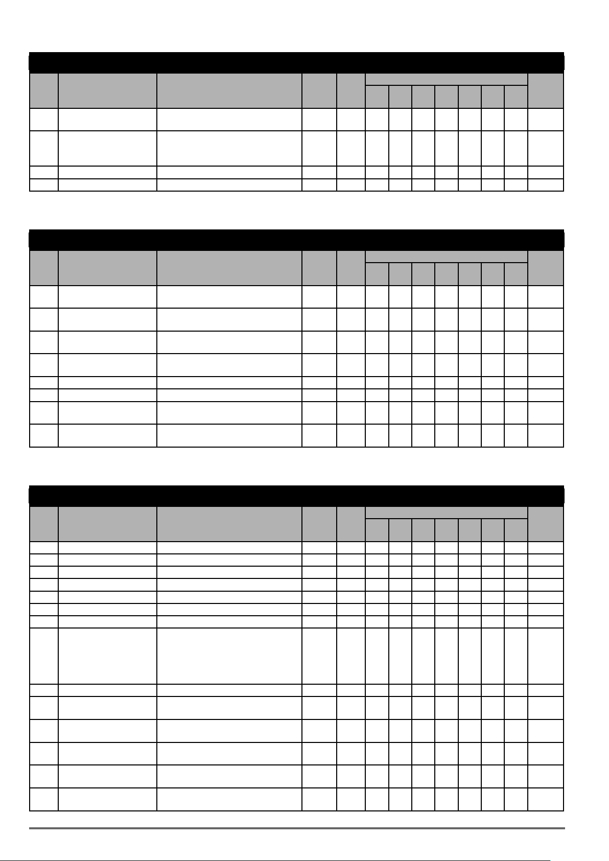
Group 18: Slip Compensation Parameters
Control mode
Code Parameter Name Setting Range Default Unit
Slip Compensation Filter
18-03
Time
Regenerative Slip Compen-
18-04
sation Selection
0.0~10.0 1.0 s O X X X X X X
0: Disable 0 - O X X X X X X
V/f
V/f
+PG
SLV SV
PM SVPM
SLV
SLV2
Attribute
1: Enable
18-05 FOC Delay Time 1~1000 100 ms X X O X X X X
18-06 FOC Gain 0.00~2.00 0.1 - X X O X X X X
*: Refer to the following attachment 1
Group 19: Wobble Frequency Parameters
Control mode
Code Parameter Name Setting Range Default Unit
Center Frequency of Wob-
19-00
ble Frequency
Amplitude of Wobble
19-01
Frequency
Jump Frequency of Wobble
19-02
Frequency
Jump Time of Wobble
19-03
Frequency
5.00~100.00 20.00 % O O X X X X O *1
0.1~20.0 10.0 % O O X X X X O *1
0.0~50.0 0.0 % O O X X X X O *1
0~50 0 ms O O X X X X O *1
V/f
V/f
+PG
SLV SV
PM SVPM
SLV
19-04 Wobble Frequency Cycle 0.0~1000.0 10.0 s O O X X X X O *1
19-05 Wobble Frequency Ratio 0.1~10.0 1.0 O O X X X X O *1
Upper Offset Amplitude of
19-06
Wobble Frequency
Lower Offset Amplitude of
19-07
Wobble Frequency
0.0~20.0 0.0 % O O X X X X O *1
0.0~20.0 0.0 % O O X X X X O *1
SLV2
Attribute
Group 20: Speed Control Parameters
Control mode
Code Parameter Name Setting Range Default Unit
20-00 ASR Gain 1 0.00~250.00
20-01 ASR Integral Time 1 0.001~10.000
20-02 ASR Gain 2 0.00~250.00
20-03 ASR Integral Time 2 0.001~10.000
S - X O O O O O X *1
S s X O O O O O X *1
S - X O O O O O X *1
S s X O O O O O X *1
20-04 ASR Integral Time Limit 0~300 200 % X X O O O O X
(1)
20-05 ASR Positive Limit 0.1 ~ 10.0 5.0
20-06 ASR Negative Limit 0.1 ~ 10.0 1.0
Selection of Acceleration
20-07
and Deceleration of P/PI
0: PI speed control will be enabled only in
constant speed. For the speed accelera-
tion and deceleration, only use P control.
% X O X X X X X
(1)
% X O X X X X X
0 - X O O O O
1: Speed control is enabled either in
acceleration or deceleration.
20-08 ASR Delay Time 0.000~0.500 0.004 s X X O O O X X
Speed Observer Proportio-
20-09
nal (P) Gain1
Speed Observer Integral(I)
20-10
Time 1
Speed Observer Proportio-
20-11
nal (P) Gain2
Speed Observer Integral(I)
20-12
Time 2
Low-pass Filter Time Con-
20-13
stant of Speed Feedback 1
0.00~2.55 0.61 - X X O X X X X *1
0.01~10.00 0.05 s X X O X X X X *1
0.00~2.55 0.61 - X X O X X X X *1
0.01~10.00 0.06 s X X O X X X X *1
1~1000 4 ms X X O X X X X
V/f
V/f
+PG
SLV SV
PM SVPM
SLV
X X
SLV2
Attribute
88 VDI100 • Instruction manual
Page 89
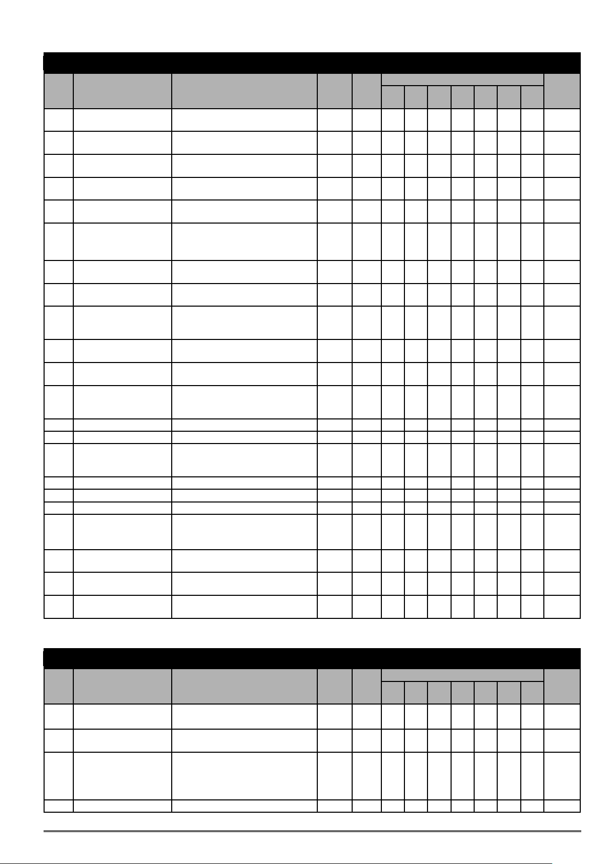
Group 20: Speed Control Parameters
Control mode
Code Parameter Name Setting Range Default Unit
Low-pass Filter Time Con-
20-14
stant of Speed Feedback 2
ASR Gain Change Frequen-
20-15
cy 1
ASR Gain Change Frequen-
20-16
cy 2
Torque Compensation Gain
20-17
at Low Speed
Torque Compensation Gain
20-18
at High Speed
1~1000 30 ms X X O X X X X
0.0~599.0 4.0 Hz X O O O O X O
0.0~599.0 8.0 Hz X X O O O X O
0.00~2.50 1.00 - X X O X X X X *1
-10~10 0 % X X O X X X X *1
20-19 Over Speed (OS) Selection 0: Deceleration to stop 1 X O X O O X X
1: Coast to stop
2: Continue to operate
Over Speed (OS) Detection
20-20
Level
Over Speed (OS) Detection
20-21
Time
Speed Deviation (DEV)
20-22
Selection
Speed Deviation (DEV)
20-23
Detection Level
Speed Deviation (DEV)
20-24
Detection Time
0~120 115 % X O X O O X X
0.0~2.0 0.5 s X O X O O X X
0: Deceleration to Stop
1: Coast to Stop
2 X O X O O X X
2: Continue to Operate
0~50 10 % X O X O O X X
0.0~10.0 0.5 s X O X O O X X
0: Deceleration to Stop
20-25 Selection of PG Open
1: Coast to Stop
1 - X O X O O X X
2: Continue to Operate
20-26 Detection Time of PG Open 0.0~10.0 2.0 s X O X O O X X
20-27 PG Pulse Number 0~9999 1024 ppr X O X O O X X
Selection of PG Rotation
20-28
Direction
0: Forward as Counter -Clockwise
Rotation
1: Forward as Clockwise Rotation
0 - X O X O O X X
20-29 PG Pulse Dividing Ratio 001~132 1 - X O X O O X X
20-30 PG Gear Ratio 1 1~1000 1 - X O X O X X X
20-31 PG Gear Ratio 2 1~1000 1 - X O X O X X X
Selection of Specific
20-32
Encoder
0: None 0 X X X O O X X
1: Resolver
Detection Level at Constant
20-33
Speed
Compensation Gain of
20-34
Derating
Compensation Time of
20-35
Derating
(1) For VF+PG control mode.
0.1~5.0 1.0 X O O O O O X *1
0~25600 0 X X O O O X X *1
0~30000 100 ms X X O O O X X *1
V/f
V/f
+PG
SLV SV
PM SVPM
SLV
SLV2
Attribute
Group 21: Torque And Position Control Parameters
Control mode
Code Parameter Name Setting Range Default Unit
V/f
V/f
+PG
SLV SV
PM SVPM
SLV
21-00 Torque Control Selection 0: Speed Control 0 - X X X O O X X
1: Torque Control
Filter Time of Torque
21-01
Reference
0~1000 0 ms X X X O O X X
21-02 Speed Limit Selection 0: According to AI Input 0 - X X X O O X X
1: According to the Set Value of 21-03
2: According to communication position
input (2502H)
21-03 Speed Limit Value -120~120 0 % X X X O O X X *1
VDI100 • Instruction manual 89
SLV2
Attribute
Page 90

Group 21: Torque And Position Control Parameters
Control mode
Code Parameter Name Setting Range Default Unit
21-04 Speed Limit Bias 0~120 10 % X X X O O X X *1
21-05 Positive Torque Limit 0~300 * % X X O O O O X
21-06 Negative Torque Limit 0~300 * % X X O O O O X
Forward Regenerative
21-07
Torque Limit
Reversal Regenerative
21-08
Torque Limit
Maximum Frequency of
21-09
Position Control
The Command of Rotation
21-10
Cycle Number of Section 0
The Command of the Pulse
21-11
Number of Section 0
The Command of Rotation
21-12
Cycle Number of Section 1
The Command of the Pulse
21-13
Number of Section 1
The Command of Rotation
21-14
Cycle Number of Section 2
The Command of the Pulse
21-15
Number of Section 2
The Command of Rotation
21-16
Cycle Number of Section 3
The Command of the Pulse
21-17
Number of Section 3
The Command of Rotation
21-18
Cycle Number of Section 4
The Command of the Pulse
21-19
Number of Section 4
The Command of Rotation
21-20
Cycle Number of Section 5
The Command of the Pulse
21-21
Number of Section 5
The Command of Rotation
21-22
Cycle Number of Section 6
The Command of the Pulse
21-23
Number of Section 6
The Command of Rotation
21-24
Cycle Number of Section 7
The Command of the Pulse
21-25
Number of Section 7
The Command of the Pulse
21-26
Number of Section 8
The Command of Rotation
21-27
Cycle Number of Section 8
The Command of the Pulse
21-28
Number of Section 9
The Command of Rotation
21-29
Cycle Number of Section 9
The Command of Rotation
21-30
Cycle Number of Section 10
The Command of the Pulse
21-31
Number of Section 10
The Command of Rotation
21-32
Cycle Number of Section 11
The Command of the Pulse
21-33
Number of Section 11
The Command of Rotation
21-34
Cycle Number of Section 12
The Command of the Pulse
21-35
Number of Section 12
0~300 * % X X O O O O X
0~300 * % X X O O O O X
0.1~100.0 20.0 Hz X X X O O X X
-9999 ~ 9999 0 - X X X O O X X
-9999 ~ 9999 0 - X X X O O X X
-9999 ~ 9999 0 - X X X O O X X
-9999 ~ 9999 0 - X X X O O X X
-9999 ~ 9999 0 - X X X O O X X
-9999 ~ 9999 0 - X X X O O X X
-9999 ~ 9999 0 - X X X O O X X
-9999 ~ 9999 0 - X X X O O X X
-9999 ~ 9999 0 - X X X O O X X
-9999 ~ 9999 0 - X X X O O X X
-9999 ~ 9999 0 - X X X O O X X
-9999 ~ 9999 0 - X X X O O X X
-9999 ~ 9999 0 - X X X O O X X
-9999 ~ 9999 0 - X X X O O X X
-9999 ~ 9999 0 - X X X O O X X
-9999 ~ 9999 0 - X X X O O X X
-9999 ~ 9999 0 - X X X O O X X
-9999 ~ 9999 0 - X X X O O X X
-9999 ~ 9999 0 - X X X O O X X
-9999 ~ 9999 0 - X X X O O X X
-9999 ~ 9999 0 - X X X O O X X
-9999 ~ 9999 0 - X X X O O X X
-9999 ~ 9999 0 - X X X O O X X
-9999 ~ 9999 0 - X
-9999 ~ 9999 0 - X X X O O X X
-9999 ~ 9999 0 - X X X O O X X
V/f
V/f
SLV SV
+PG
X X O O X X
PM SVPM
SLV
SLV2
Attribute
90 VDI100 • Instruction manual
Page 91

Group 21: Torque And Position Control Parameters
Control mode
Code Parameter Name Setting Range Default Unit
The Command of Rotation
21-36
Cycle Number of Section 13
The Command of the Pulse
21-37
Number of Section 13
The Command of Rotation
21-38
Cycle Number of Section 14
The Command of the Pulse
21-39
Number of Section 14
The Command of Rotation
21-40
Cycle Number of Section 15
The Command of the Pulse
21-41
Number of Section 15
21-42 Pos. Mode Sel
21-43 Offset Angle 0 ~9999 0 Pulse X X X O O X X
* Refer to the following attachment 1.
-9999 ~ 9999 0 - X X X O O X X
-9999 ~ 9999 0 - X X X O O X X
-9999 ~ 9999 0 - X X X O O X X
-9999 ~ 9999 0 - X X X O O X X
-9999 ~ 9999 0 - X X X O O X X
-9999 ~ 9999 0 - X X X O O X X
0: Switch to position mode when output
frequency < 01-08.
1: Z Phase Locked Function
0 X X X O O X X
V/f
V/f
+PG
SLV SV
PM SVPM
SLV
Group 22: PM Motor Parameters
Control mode
Code Parameter Name Setting Range Default Unit
22-00 PM Motor Rated Power 0.00~600.00
22-01 Reserved
22-02 PM Motor Rated Current 25%~200% inverter’s rated current S A X X X X O O X
22-03 PM Motor ‘s Pole Number 2~96 6 poles X X X X O O X
22-04 PM Motor’s Rotation Speed 1~30000 1500 rpm X X X X O O X
PM Motor’s Maximum
22-05
Rotation Speed
22-06 PM Motor Rated Frequency 0.1~599.0 75.0 Hz X X X X O O X
22-07 Reserved
22-08 PM Encoder Type 0: TAMAGAWA Non Wire-Saving Encoder 0 X X X X O X X
22-09 Reserved
22-10 PM SLV Start Current
I/F Mode Start Frequency
22-11
Switching Point
KP Value of Speed Esti22-12
mation
KI Value of Speed Estima22-13
tion
Armature Resistance of PM
22-14
Motor
D-axis Inductance of PM
22-15
Motor
Q-axis Inductance of PM
22-16
Motor
22-17 Reserved
22-18 Flux-Weakening Limit 0~100 0 % X X X X O O X
22-19 Reserved
Offset Angle of the Magne-
22-20
tic Pole and PG Origin
22-21 PM Motor Tuning 0: PM Motor Tuning is not Active. 0 - X X X X O O X
1~60000 1500 rpm X X X X O O X
1: TAMAGAWA Wire-Saving Encoder
2: SUMTAK Wire-Saving Encoder
3: General Incremental Encoder
4:Sine Wave
20 ~ 120%
Motor Rated Current
1.0 ~ 20 5 % X X X X X O X
1~10000 2000 - X X X X X O X
1~1024 40 - X X X X X O X
0.001 ~ 30.000 1.000 Ω X X X X O O X
0.01 ~ 300.00 10.00 mH X X X X O O X
0.01 ~ 300.00 10.00 mH X X X X O O X
0~360 0 deg X X X X O X X *4
1: Auto tune for PMSLV
S kW X X X X O O X
50 % X X X X X O X
V/f
V/f
+PG
SLV SV
PM SVPM
SLV
SLV2
SLV2
Attribute
Attribute
VDI100 • Instruction manual 91
Page 92

Group 22: PM Motor Parameters
Control mode
Code Parameter Name Setting Range Default Unit
2: Auto tune for PMSV
Fault History of PM Motor
22-22
Tuning
22-23 PM SLV acceleration time 0.1~10.0 1.0 s X X X X X O X
0. No Error 0 - X X X X O O X *4
1. Static Magnetic Alignment Fault
2. Without PG Option Card
3. Rotation Pole Alignment is Forced to
Stop
4. Error of Encoder Feedback Direction
5. Loop Adjustment is Time out
6. Encoder Error
7. Other Errors of Motor Tuning
8. Current Abnormity Occurs when
Aligning Rotation Magnetic Pole.
9. Current Abnormity Occurs while Loop
Adjustment.
10. Reserved
11. Stator Resistance Measurement
Timeout
V/f
V/f
+PG
SLV SV
PM SVPM
SLV
SLV2
Attribute
4.3.1. Attachment 1: Parameters’ default value and upper limit value are adjusted by different inverter
sizes
Max. frequency in SLV
when carrier frequency
kHz
Models Size
1007
1015
2022
2037
2055
3075 3 150 150 Yes 1.00
4110
4150
4185
5220 5 100 80 Yes 0.70
1007
1015
1022
2037
2055
3075
3110
3150
4150
4185
4220
5300
5370
5450
5500
6750
6900
1 150 150 Ye s 1.00
2 150 150 Ye s 1.00
4 110 110 Ye s 1.00
1 150 150 Ye s 1.00
2 150 150 Ye s 1.00
3 150 150 Ye s 1.00
4
5 100 80 Yes 0.70
6 100 80 No 0.70
≤ 8
11-01
(Hz) (Hz)
110 110 Ye s 1.00
100 100 Ye s 1.00
Max. frequency (Hz)
in SLV when carrier
frequency > 8 kHz
11-01
230V Class
400 V Class
Display parameter 12-41
(Inverter temperature)
The initial value of pa-
rameter 18-00 in SLV/ SV
(Slip compensation at low
speed)
92 VDI100 • Instruction manual
Page 93

Max. frequency in SLV
when carrier frequency
≤ 8
Models Size
71100
71320
71600
The initial value
of parameters
Models
1007
1015 8 8 16
2022
2037 8 8 16
2055
3075 8 8 16
4110
4150 8 8 16
4185 6 8 12
5220 160% 0.002 385 20.0 5 8 12
1007
1015 8 8 16
1022 8 8 16
2037
2055 8 8 16
3075
3110 8 8 16
3150
4150
4185 8 8 16
4220 8 8 16
5300
5370 5 8 12
5450 5 8 10
5550
6750 5 8 10
6900
71100 5 8 10
71320 5 8 10
71600 3 8 8
21-05 ~21-08
(Torque Limit) (ASR Filter Time)
7 100 80 No 0.50
The initial value
(s) of parameter
20-08
200% 0.001 395 10.0
200% 0.001 395 10.0
200% 0.001 395 10.0
200% 0.002 385 15.0
200% 0.001 790 10.0
200% 0.001 790 10.0
200% 0.001 790 10.0
200% 0.002 770 15.0
160% 0.002 770 20.0
160% 0.004 770 20.0
160% 0.004 770 20.0
kHz
11-01
(Hz) (Hz)
The initial value
(V) of parameter
(Stall Level in
Deceleration)
Max. frequency (Hz)
in SLV when carrier
frequency > 8 kHz
08-02
230V Class
400 V Class
11-01
The initial value
of Accel. & Decel
00-14~00-17 &
00-23~00-27
(s) kHz
Display parameter 12-41
(Inverter temperature)
Default carrier
in HD
11-01
kHz (SLV, Max. >
8 8 16
8 8 16
8 8 16
8 8 16
8 8 16
8 8 16
8 8 16
8 8 16
5 8 12
5 8 10
4 8 10
rameter 18-00 in SLV/ SV
(Slip compensation at low
Max. carrier
in HD
11-01
80Hz)
The initial value of pa-
speed)
Max. carrier
in HD
11-01
(others)
kHz
230V Class Models
01-09
Model
1007
1015
2022
2037
2055
3075
4110
4150
4185
5220 7.5V 14.0V 7.5V 14.0V 0.01 10
VDI100 • Instruction manual 93
Minimum Output
Voltage 1 of Motor 1
7.9V 14.8V 7.9V 14.8V 0.05 100
7.5V 14.0V 7.5V 14.0V 0.05 100
7.5V 14.0V 7.5V 14.0V 0.05 100
7.5V 14.0V 7.5V 14.0V 0.01 10
01-07
Middle Output Volt-
age 1 of Motor 1
01-23
Minimum Output
Voltage 1 of Motor 2
01-21
Middle Output Volt-
age 1 of Motor 2
11-59
Gain of Preventing
Oscillation
11-60
Upper Limit of Preventing Oscillation
Page 94

400V Class Models
1
Model
1007
1015
01-09
Minimum Output
Voltage 1 of Motor 1
15.8V 25.6V 15.8V 25.6V 0.05 100
01-07
Middle Output
Voltage 1 of Motor 1
01-23
Minimum Output
Voltage 1 of Motor 2
01-21
Middle Output
Voltage 1 of Motor 2
11-59
Gain of Preventing
Oscillation
11-60
Upper Limit of
Preventing Oscillation
1022 15.0V 28.0V 15.0V 28.0V 0.05 100
2037
2055
15.0V 28.0V 15.0V 28.0V 0.05 100
3075 15.0V 28.0V 15.0V 28.0V 0.05 100
3110 15.0V 28.0V 15.0V 28.0V 0.05 10
3150
4150
4185
15.0V 28.0V 15.0V 28.0V 0.01 10
4220
5300
5370
17.0V 30.0V 17.0V 30.0V 0.01 10
5450
5550
6750
17.0V 30.0V 17.0V 30.0V 0.01 10
6900
71100
71320
17.0V 30.0V 17.0V 30.0V 0.01 10
71600
4.3.2. Low Voltage Detection Level Function
Wiring:
2
UPS or
battery
1-Phase UPS or Battery
3
~
AC Motor Drive
R/L1
S/L2
T/L3
440V Vac: 207~380
Vdc: 292~537
3
Execute Low Voltage
Detection Level Input
S1~S8
24VG
Timing Diagram of Magnetic Contactor
1
2
3
Before inputting emergency power, magnetic contactor ①and ③ are ON and
magnetic contactor ② should be OFF. Magnetic contactor ③ should be ON
after magnetic contactor is ON. Before removing battery and turning magnetic
contactor ② to be ON, Magnetic contactor ①and ③ should be OFF.
Notes for the emergency power supply. Please be aware of the following condition
when emergency power is ON:
1. Execute Low Voltage Function ON (DI=62),Fan doesn’t run.
2. Execute Low Voltage Function ON (DI=62),No phase loss.
3. Execute Low Voltage Function ON (DI=62),run frequency of motor depends on
the value of07-31
94 VDI100 • Instruction manual
Page 95

4.4. Description of Parameters
00 - Basic Parameters
Code Parameter Name / Range
00-00 Control mode selection
0: V/f
1: V/f+PG
2: SLV
3: SV
4: PMSV
5: PMSLV
6: SLV2
The inverter offers the following control modes:
Value Mode Info Application
0 V/f V/f Control without PG General Purpose Applications which do not require high precision speed control
.
Auto-tuning is not required.
1 V/f+PG V/f Control with PG (speed
compensation)
2 SLV Sensorless Vector Control
without PG
3 SV Closed Loop Vector Control with PGGeneral Purpose Applications that require high precision speed control and
4 PMSV PM Vector Control with PG (Per-
manent Magnet Vector Control)
5 PMSLV Sensorless Current Vector Con-
trol without PG (for Permanent
magnet motor)
6 SLV2 Voltage vector control without PGWithout PG Applications. Vector control provides high speed rotation and the
Closed loop speed control for General purpose applications that require better
speed control than V/f mode without PG.
General Purpose Applications that require higher precision speed control and
torque response without the use of an encoder.
torque response with the use of an encoder.
PM Motor Applications that require high precision speed control and torque
response with the use of an encoder.
Without PG Applications. Provide the requirements of high precision speed and
torque
requirements of higher precision speed than V/f and torque.
See “Table 3.18.1: Maximum output frequency for each control mode” on page
35.
00-00=0:V/fMode
Select the required V/f curve (01-00) based on your motor and applications.
Perform a stationary auto-tune (17-00=2), if the motor cable is longer than 50m (165ft), see parameter 17-00
for details.
00-00=1:V/fwithPG
Select the required V/f curve (01-00) based on your motor and applications. Set number of motor poles (02-08)
and encoder feedback pulses (20-27); refer to parameter group 20 for PF feedback setup. Perform a stationary
auto-tune (17-00=2) if the distance between the inverter and the motor more than 50m (165ft), refer to parameter group 17 for details on auto-tuning.
00-00=2: Sensorless Vector Control
Verify the inverter rating matches the motor rating. Perform rotational auto-tune to measure and store motor
parameters for higher performance operation. Perform non-rotational auto-tune if it’s not possible to rotate the
motor during auto-tune. Refer to parameter group 17 for details on auto-tuning.
00-00=3: Closed Loop Vector Control
Verify the inverter rating matches the motor rating. Perform rotational auto-tune to measure and store motor
parameters for higher performance operation. Perform non-rotational auto-tune if it’s not possible to rotate the
motor during auto-tune. Refer to parameter group 17 for details on auto-tuning.
00-00=4: PM Vector Control
Verify the inverter rating matches the motor rating. Set PM motor data in parameters 22-00 to 22-06 and encoder feedback pulses in parameter 20-27. Refer to parameter 22-21 for details on PM Motor tuning.
Select the appropriate motor rating and braking resistor based on your motor and applications. Please install
the braking module in the models of
230V Class 22 kW / 400V Class 30 kW or the above.
00-00=5: PM Sensorless Vector Control
Verify the inverter rating matches the motor rating. Perform rotational auto-tune to measure and store motor
VDI100 • Instruction manual 95
Page 96

parameters for higher performance operation.
Perform auto-tuning before operation to enhance the performance of PMSLV mode. Refer to parameter 22-21
for the descriptions of PM motor tuning function.
Select the appropriate motor rating and braking resistor based on your motor and applications. Please install
the braking module in the models of
230V Class 22 kW / 400V Class 37 kW or the above.
00-00=6: SLV2 Vector Control
Verify the inverter rating matches the motor rating. Perform rotational auto-tune to measure and store motor
parameters for higher performance operation.
Refer to parameter group 17 for the descriptions of motor parameter tuning function.
Select the required V/f curve (01-00) based on your motor and applications.
Note ! Parameter 00-00 is excluded from initialization.
Code Parameter Name / Range
00-01 Motor’s rotation direction
0: Forward
1: Reverse
Use the FWD/REV key to change motor direction when Run Command Selection (00-02 = 0) is set to keypad
control.
Code Parameter Name / Range
00-02 Run command selection
0: Keypad control
1: External terminal control
2: Communication control
3: PLC
00-02=0: Keypad Control
Use the keypad to start and stop the inverter and set direction with the forward / reverse key). Refer to section
4-1 for details on the keypad.
00-02=1: External terminal control
External terminals are used to start and stop the inverter and select motor direction.
Code Parameter Name / Range
00-03 Alternative RUN Command Selection
0: Keypad control
1: External terminal control
2: Communication control
3: PLC
00-03=0: Keypad Control
Use the keypad to start and stop the inverter and set direction with the forward / reverse key). Refer to section
4-1 for details on the keypad.
00-03=1: External terminal control
External terminals are used to start and stop the inverter and select motor direction.
*Itisrequiredtobewithmulti-functiondigitalinput(12:mainandalternativerunswitchfunction).
The inverter can be operated in either 2-wire or 3-wire mode.
■ 2-wire operation
For 2-wire operation set 03-00 (S1 terminal selection) to 0 and 03-01 (S2 terminal selection) to 1.
Terminal S1 Terminal S2 Operation
Open Open Stop Inverter / FWD Active
Closed Open Run Forward
Open Closed Run Reverse
96 VDI100 • Instruction manual
Page 97
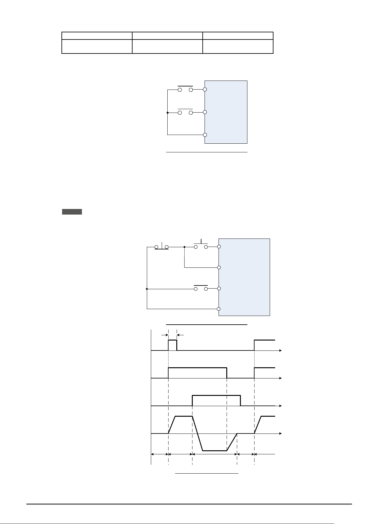
Terminal S1 Terminal S2 Operation
Forward,
Closed Closed Stop Inverter, Display EF9 Alarm
after 500ms
Parameter 13-08 to 2, 4 or 6 for 2-wire program initialization, multi-function input terminal S1 is set to forward ,
operation/ stop, and S2 is set for reverse, operation / stop.
Run / Stop
Reverse
Run / Stop
S1
S2
24VG
Figure4.4.1wiringexampleof2-wire
■ 3-wire operation
For 3-wire operation set any of parameters 03-02 to 03-07 (terminal S3 ~ S8) to 26 to enable 3-wire operation
in combination with S1 and S2 terminals set to run command and stop command.
Parameter 13-08 to 3, 5 or 7 for 3-wire program initialization, multi-function input terminal S1 is set to run operation, S2 for stop operation and S7 for forward/reverse command.
Note ! Terminal S1 must be closed for a minimum of 50ms to activate operation.
Operation
(normally open
Momenta ry switch)
Run Comma nd
S1
Stop
(Normally closed
Momenta ry
switch)
(On:Run)
Stop Command
S2
(Off: Stop)
Run Command
Stop Command
Forward/Reverse
Command
Motor Speed
Forward/R everse
S7
selection
24VG
Figure4.4.2wiringexampleof3-wire
>= 50ms
On
Off
(forward)
Stop Forward Reverse Stop Forward
Off
On (Reversal)
Off
(Stop)
Time
Time
Time
Time
VDI100 • Instruction manual
Figure4.4.33-wireoperation
97
Page 98
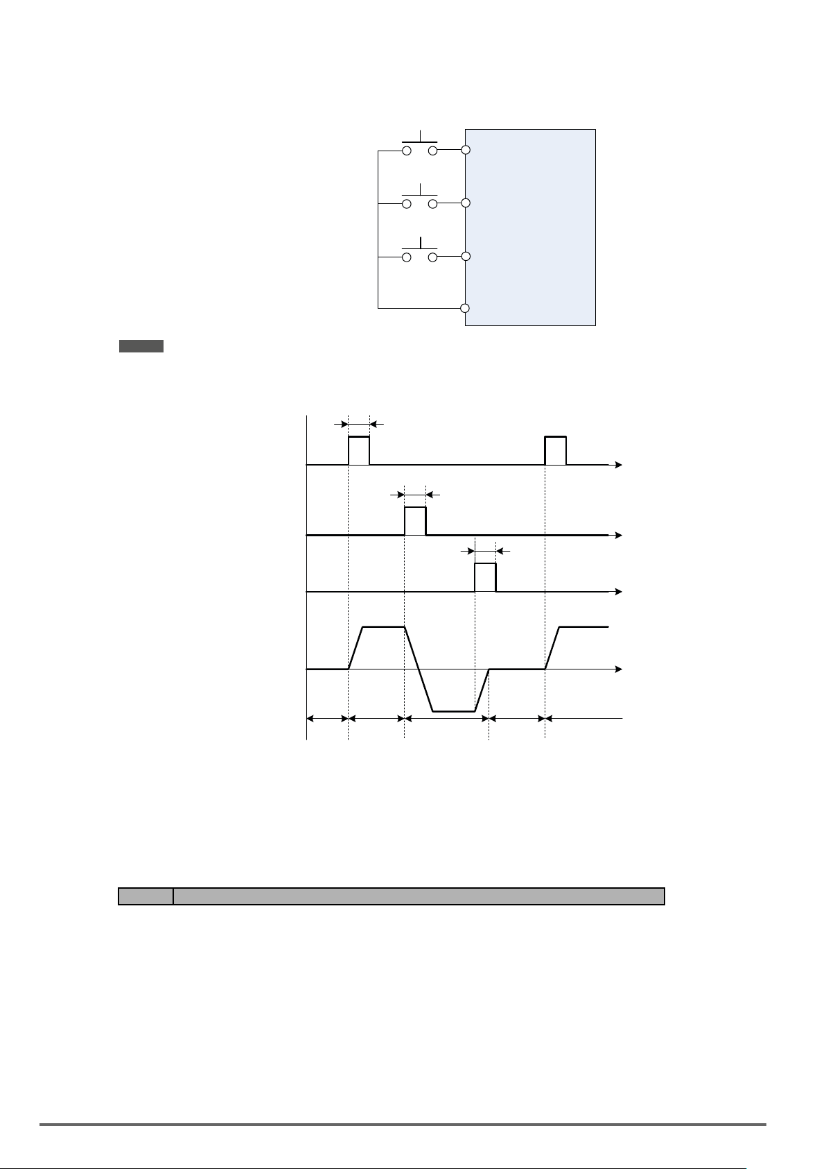
■ 2-wire operation with hold function
To enable 2-wire operation with hold function set any of parameters 03-02 to 03-07 (terminal S3 ~ S8) to 53.
When this mode is enabled set terminal S1 (03-00=0) to forward and S2 (03-01=1) to reverse run command.
Forward Run Command
S1
(On: Run Forward)
Reverse Run Command
Momentary switches
(Push buttons)
S2
(On: Run Reverse)
S5
Stop
(On: Stop)
24VG
Note ! Terminal S1, S2 and S5 must be closed for a minimum of 50ms to activate operation.
The inverter will display SE2 error when input terminals S1-S8 is set to 53 and 26 simultaneously.
>50 ms
Forward
Command
Reverse
Command
Stop
Command
Motor
Speed
Stop
ON
ON
OFF
OFF
(Inverter On)
Forward Reverse
OFF
>50 ms
OFF
ON
>50 ms
Stop
ON
OFF
Time
Time
Time
Time
Forward
00-02=2: Communication control
The inverter is controlled by the RS-485 port. Refer to parameter group 9 for communication setup.
00-02=3: PLC control
The inverter is controlled by the inverter built-in PLC logic. Refer to section 4.5.
Code Parameter Name / Range
00-04 Language
0: English
1: Simplified Chinese
2: Traditional Chinese
3: Turkish
It is required to be with LCD keypad to display the language selection of parameter 00-04.
00-04=0, LCD keypad displays in English.
00-04=1, LCD keypad displays in Simplied Chinese.
00-04=2, LCD keypad displays in Traditional Chinese.
00-04=3, LCD keypad displays in Turkish.
98 VDI100 • Instruction manual
Page 99
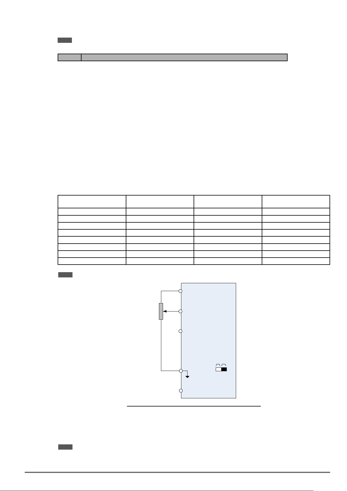
Note: It will not restore to the default value when this parameter performs initialization.
Code Parameter Name / Range
00-05 Main Frequency Command Source Selection
00-06 Alternative Frequency Source Selection
0: Keypad
1: External control (analog)
2: Terminal UP / DOWN
3: Communication control
4: Pulse input
5: Reserved
6: Reserved
7: AI2 Auxiliary Frequency
00-05/00-06=0:Keypad
Use the digital operator to enter frequency reference or to set parameter 05-01 (frequency reference 1) as
alternative frequency reference source. Refer to section 4.1.4 for details.
00-05/00-06=1:Externalcontrol(AnalogInput)
Use analog reference from analog input AI1 or AI2 to set the frequency reference (as shown in Figure 4.4.4).
Refer to parameters 04-00 to select the signal type.
AI1 – Analog Input 1 AI2 – Analog Input 2 04-00 Setting
(Default = 1)
Dipswitch SW2
(Default ‘V’)
0 ~ 10V 0 ~ 10V 0 Set to ‘V’
0 ~ 10V 4 ~ 20mA 1 Set to ‘I’
-10 ~ 10V 0 ~ 10V 2 Set to ‘V’
-10 ~ 10V 4 ~ 20mA 3 Set to ‘I’
0 ~ 12V 0 ~ 12V 4 Set to ‘V’
0 ~ 12V 4 ~ 20mA 5 Set to ‘I’
-12 ~ 12V 0 ~ 12V 6 Set to ‘V’
-12 ~ 12V 4 ~ 20mA 7 Set to ‘I’
Note: Set parameter 04-05 to 10 to add frequency reference using AI2 to AI1.
+10V
Main Spee d
Frequen cy Reference
Ω
2K
AI1
(Voltage I nput)
AI2
Frequen cy Reference
(Current Input)
GND
-10V
Command
Main Spee d
Command
I
SW2
V
Figure4.4.4Analoginputasmainfrequencyreferencecommand
00-05/00-06=2:TerminalUP/DOWN
The inverter accelerates with the UP command closed and decelerates with the DOWN command closed.
Please refer to parameter 03-00 ~ 03-07 for additional information.
Note: To use this function both the UP and DOWN command have to be selected to any of the input terminals.
00-05/00-06=3:Communicationcontrol
VDI100 • Instruction manual 99
Page 100

The frequency reference command is set via the RS-485 communication port using the MODBUS RTU protocol.
Refer to parameter group 9 for additional information.
00-05/00-06=4:Pulseinput
To use this function a pulse train input is required to be connected to the PI input and GND (see g. 4.4.5).
Set parameter 03-30 to 0 to use the pulse input as frequency reference. Refer to parameters 03-31 to 03-34 for
pulse input scaling.
PI input terminal, built-in resistance, is not required to connect the resistance if open collector input mode is
used.
PI
GND
0V
Figure4.4.5Frequencyreferencefrompulseinput
Serial pulse input
(Internal resistence : 3.89 K)
Specification
Low Input Level: 0.0 to 0.5 V
High Input Level: 4.0 to 13.5 V
Duty cycle: (ON / OFF) 30 % to 70%
Pulse Input frequency range: 50 to 32 KHz
00-05/00-06=7:AI2AuxiliaryFrequency
When 04-05 is set to 0 (auxiliary frequency), frequency command is provided by multi-function analog input AI2
and the maximum output frequency (01-02, Fmax) = 100%.
When 04-05 is not set to 0, the frequency is 0. Refer to p4-76 for multi-speed descriptions.
Code Parameter Name / Range
00-07 Main and Alternative Frequency Command modes
0: Main frequency
1: Main frequency + alternative frequency
When set to 0 the reference frequency is set by the main reference frequency selection of parameter 00-05.
When set to 1 the reference frequency is sum of the main reference frequency (00-05) and alternative frequency (00-06).
Note: The inverter will display the SE1 error when 00-07 = 1 and parameter 00-05 and 00-06 are set to the same selection.
When parameter 00-06 is set to 0 (Keypad) the alternative frequency reference is set by parameter 05-01 (Frequency setting of speed-stage 0).
Code Parameter Name / Range
00-08 Communication frequency command – READ ONLY
0.00~599.00 Hz
Display the frequency reference when 00-05 or 00-06 is set to communication control (3).
Code Parameter Name / Range
00-09 Communication frequency command memory
0: Don’t save when power supply is off. (00-08)
1: Save when power is off. (00-08)
Note: This parameter is only enabled in communication mode.
Code Parameter Name / Range
00-10 Minimum frequency detection
0: Show warning if lower than minimum frequency
1: Run as minimum frequency if lower than minimum frequency
00-10=0: Frequency command is lower than 01-08 (Minimum Output Frequency of Motor 1), it shows STP0
warning.
100 VDI100 • Instruction manual
 Loading...