

Page 1
TR
Moving Half-shell
Fixed Half-shell
FORCE TRANSDUCER FOR MEASURING THE TENSION
ON FIXED OR ROTATING SPINDLES
Main features
• Range of measurement: from 100 N to 2kN
• Accuracy class: 0,5%
• Corrosion resistant
• Internally generated calibration signal
• Orientation of the axis of maximum sensitivity for 35°
independently from the position of the fixing holes
• Grade of protection: IP65 (DIN 40050)
• Integrated protection against overloads
TR series force transducers are used to measure the tension
that plastic films or tapes exert on the guide rollers of the
machinery used to coil them.
Mounted at the ends of a fixed or transmission shaft on the
machine chassis, they perform the function of force sensors
and bearing for the ends of the shaft.
They are used on both fixed and rotating shafts.
TR transducers are supplied with the adaptor flange for fixing,
with 4 M6 screws or with one central M10 or M12 screw.
TECHNICAL DATA
Accuracy
Nominal full scale load (Ln)
Nominal output at FSO
Output tolerance at Ln
Combined errors: Non linearity
Histeresis, Repeatibility
Creep (after 30 min. at Ln)
Zero load out of balance signal
Thermal drift in Sensitivity
compensated Zero
range Calibration
Nominal bridge resistance
Isolation resistance
Nominal supply voltage
Maximum supply voltage
Compensated temperature range
Maximum temperature range
Storage temperature range
Permitted static load
Maximum applicable load
Rupture load
Maximum static lateral load
Maximum elastic deformation at Ln
Grade of protection (DIN40050)
Electr. connections: Connector
Elastic element material
Case material
0,50%
100N...2kN
2mV/V
<± 1% FSO
< ± 0,5% FSO
< ± 0,06% FSO
< ± 1% FSO
< ± 0,005% FSO°C
< ± 0,01% FSO°C
-
350 Ohm
> 10 GOhm
10V
15 V
-10...+50°C
-20...+60°C
-30...+80°C
100% Ln
300% Ln
> 500% Ln [6 kN max.]
150% Ln
< 0,5 mm
IP65
VPT02A10-6PT2
Aluminium (100...1kN)
Stainless steel (1.5kN - 2 kN)
Anodised aluminium (Flange
and bearing in AISI 303)
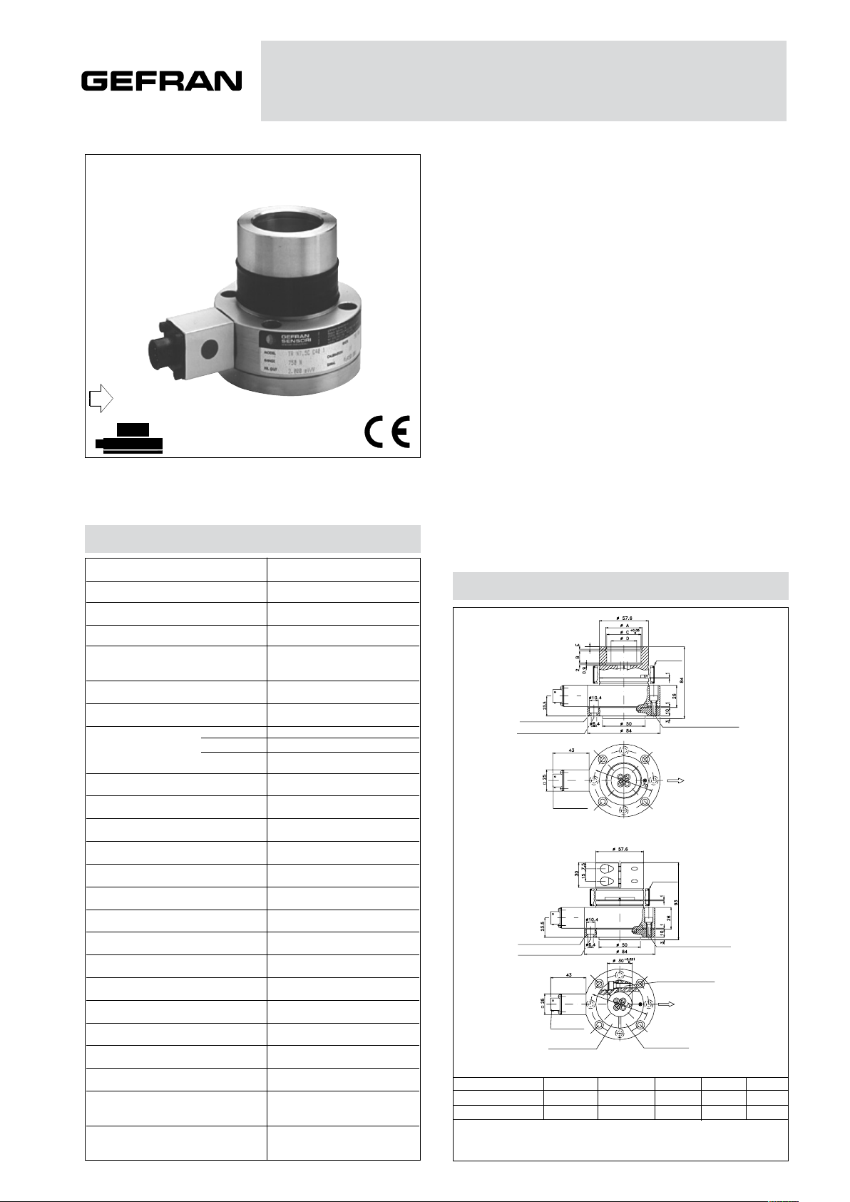
MECHANICAL DIMENSIONS
Model for
rollers with
revolving hub.
FLA705 Std Flange
4 seats for M6 fixing screws
of the cover
Model for
rollers with
fixed hub.
FLA705 Std Flange
4 seats for M6 fixing screws
of the cover
Cuscinetto
35x15 H11
40x17 H12
Valori delle misure in millimetri (± 0,1)
Coppia di serraggio consigliata per le viti di fissaggio M6 di 7Nm
VPT02A10-6PT2
CONNECTOR
VPT02A10-6PT2
CONNECTOR
øA
37
42,5
3
B
14,5
14,25
Neoprene
Sleeve
Nϒ 4 M6 case screws to
prevent the bearing support
from rotating.
Direction of the axis of max.
sensitivity of the load cell
(Indicated by a red dot on the
bearing support).
Neoprene
Sleeve
Nϒ 4 M6 case screws to
prevent the bearing support
from rotating.
Nϒ 4 M6x20 screws for
tightenning the half shells
of the fixed hub support.
Direction of the axis of max.
sensitivity of the load cell
(Indicated by a red dot on the
bearing support).
øC
35
40
øD
20
30
E
1,6
1,85
Page 2
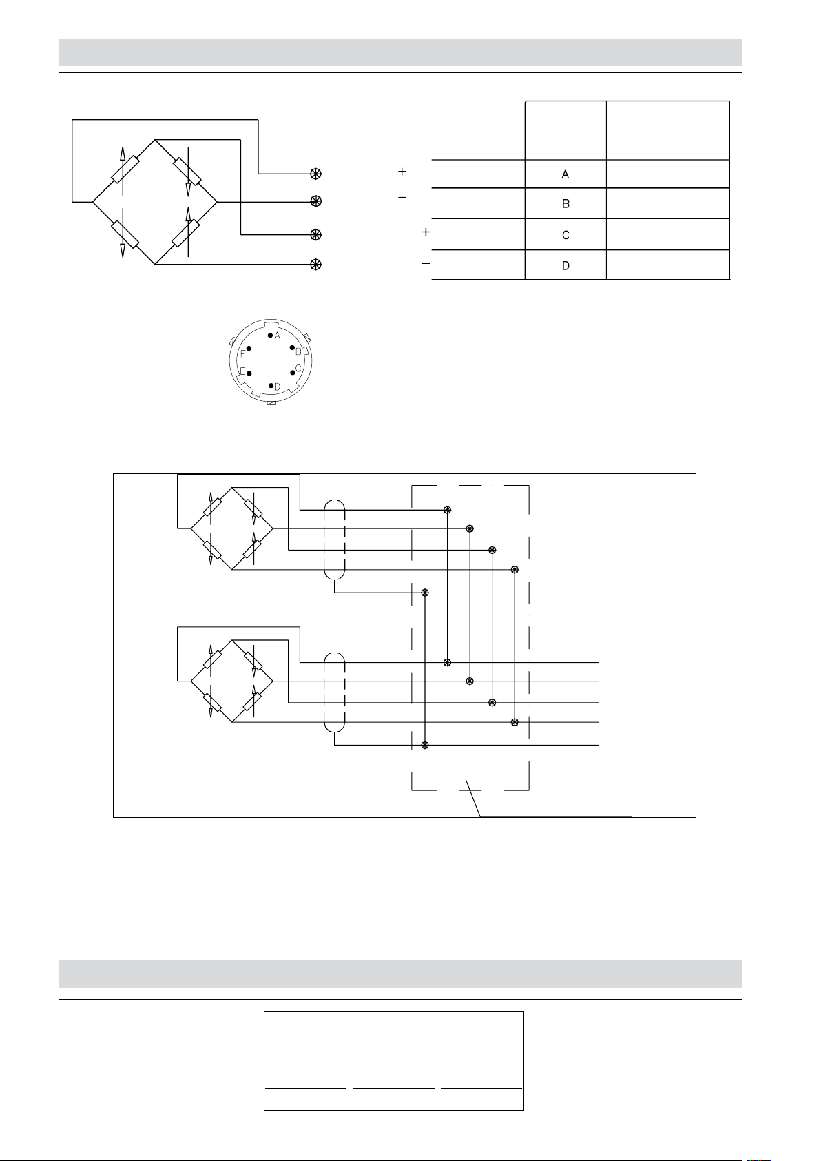
ELECTRICAL CONNECTIONS
SHUNT BOX
Cells connected in parallel
VPT02A10-6PT2
CONNECTOR
CABLE
OUTPUT
SIGNAL
SIGNAL
EXCITATION
EXCITATION
If the transducer is supplied complete with prewired
connection cable, the colour code is that indicated in
the table.
Red
Yellow or Black
White
Green
Yellow-Green
CABLE
CONNECTION
Red
Yellow or Black
White
Green
Red
Yellow or Black
White
Green
Yellow-Green
In systems that use several cells, the parallel connection automatically sums the loads on each individual
cell.
Using this method of measurement, the maximum load will be the sum of the loads on the individual cells
and the sensitivity will be the average value of these cells.
It is important that the user ensures that no cell is stessed beyond its maximum rating under any load condition.
CONVERSION TABLE
Kg
1
N
9.807
Lb
2.205
0.102
0.454
1
4.448
0.225
1
Page 3

FLANGE
SEAT FOR M10* FIXING
SCREW OF THE SUPPORT
SEAT FOR M12* FIXING
SCREW OF THE SUPPORT
Standard adaptor flange
(see mechanical dimensions drawing) FLA705 Central fixing FLA711
Central fixing FLA715
FLA711
FLA715
SCREW OF THE COVER
4 SEATS FOR M6 FIXING
SCREW OF THE LOAD CELL TO CARTER
4 SEATS FOR M6 FIXING
* Recommended torque 75Nm
CALCULATION OF RESULTANT APPLIED TO CELL
F = Resultant T = Tension in laminate P = Roll weight
The red point on the bearing support identifies the axis of maximum cell sensitivity and therefore the direction
that F has to take with respect to the transducer.
The formulas are valid for the configuration with two load cells where the forces (T and P) will be divided on
both cells
T
2
This configuration gives the
best performance because
it does not consider roll
weight.
It is advised for low tension,
to prevent roll weight from
representing an excessive
fraction of the resultant,
with consequent reduction
of the usable field.
This is the only configuration in which, in the absence of tension T, there is a
zero signal of approximately 0 mV/V.
HORIZONTAL
RESULTANT
F = ---- • 2 • cos a
VERTICAL
RESULTANT
T P
F = ---- • 2 • cos a + ----
2 2
In this configuration, roll
weight is completely in
the direction of maximum
sensitivity of the cell that
generates a signal in mV/V
positive.
This signal should be considered as tare: it will be considered during calibration of
the instrument connected to
the cell.
DOWNWARD
RESULTANT
T P
F = ---- • 2 • cos a + ---- • COS b
2 2
In this configuration, roll
weight is completely in
the direction of maximum
sensitivity of the cell that
generates a signal in mV/V
positive.
This signal should be considered as tare: it will be considered during calibration of
the instrument connected to
the cell.
UPWARD
RESULTANT
T P
F = ---- • 2 • cos a - ---- • COS b
2 2
In this configuration, roll
weight is completely in
the direction of maximum
sensitivity of the cell that
generates a signal in mV/V
negative.
This signal should be considered as tare: it will be considered during calibration of
the instrument connected to
the cell.
Page 4

OPTIONAL ACCESSORIES
Radial bearing with stop ring (UNI7437-75) and spacer 35 mm PKIT 602
40 mm PKIT 600
Female cable connector Grade of protection IP65 CON 300
6-pin connector with 8m (25ft) cable C08W
6-pin connector with 15m (50ft) cable C15W
6-pin connector with 25m (75ft) cable C25W
6-pin connector with 30m (100ft) cable C30W
Other lengths
consult factory
TR application manual DOC467
ORDER CODE
Force transducer TR
If request, it is possible to sup-
MEASUREMENT RANGE (N)
0 - 100
0 - 200
0 - 350 N3.5C
0 - 500 N5C
0 - 750 N7.5C
0 - 1000 N1M
0 - 1500 N15C
0 - 2000 N20C
N1C
N2C
ply models with non-standard
mechanical and/or electrical
features.
FLANGE
FLA 705 (standard)
1
FLA711
2
FLA715
3
Cable colour code
Conn. wires
A
B
C
D
E
F
Red
Black
White
Green
Blue
Orange
EXTERNAL DIAMETER
35 mm bearing
40 mm bearing
30 mm shaft spindle
C35
C40
P30
Ex.: TR-N3.5C-C40-1
TR force transducer, measurement range 350N, external bearing diameter of 40mm with normal mounting and standard flange.
GEFRAN spa reserves the right to make any kind of design or functional modification at any moment without prior notice.
DTS_TR_01_2019_ENG
 Loading...