

Page 1
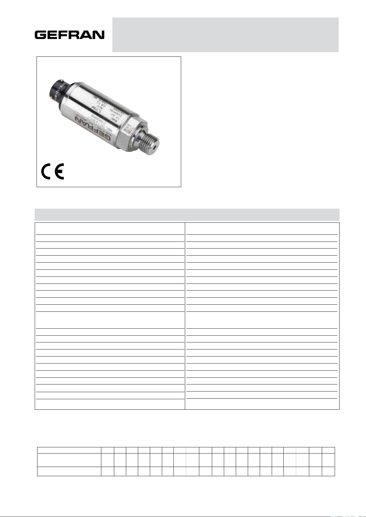
TPS
PRESSURE TRANSDUCER
Main features
• Ranges:from0...10barto0...1000bar
(0...150psito0...15000psi)
• Accuracy:±0.15%FSOtypical
• Protectionrating:IP65/IP67
• Wettedparts17-4PH
• Temperaturerange-40...+120°C
Series TPS transducers are based on the extensimetric measurement
principle with strain gauges on metal base.
An innovative mechanical structure makes the transducer completely
insensitive to tightening during installation.
This transducer is suitable for all those applications where in addition
to ruggedness and reliability high accuracy is required.
TECHNICAL DATA
Overpressure (without degrading performance) (2)
Operating temperature range (process) (5)
Temperature effects over compensated range (zero-span)
Accuracy (1)
Resolution
Pressure containment (Burst test) (3)
Wetted parts
Body materials
Power supply
Common mode voltage
Output impedance
Load impedance
Insulation resistance
Zero offset and span setting
Output voltage (sensitivity)
Long term stability
Compensated temperature range (4)
Storage temperature range
Mounting position effects
Humidity
Weight
Mechanical shock
Vibrations
Ingress protection
± 0.15% FSO typical; ± 0.2% FSO max >200bar/3000psi
± 0.25% FSO typical; ± 0.5% FSO max ≤200bar/3000psi
Infinite
See table
Fluid compatible with INOX 17-4PH Stainless Steel
INOX AISI 304 Stainless Steel and Nylon 66GF35V0
10...40bar / 150...500psi 1,5mV/V
50...60bar / 750...1000psi 2mV/V
100...1000bar / 1500...15000psi 3mV/V
-40...+120°C (-40...+248°F)
-40...+125°C (-40...+257°F)
± 0.01% FSO/°C typical (± 0.02% FSO/°C max.)
Up to 100% RH non condensing
100 g / 11 msec. according to IEC 60068-2-27
20 g max @ 10-2000Hz according to IEC 60068-2-6
See table
10 (max 15) Vdc/ac RMS
Typical 5V @ 10V supply
350 Ω (± 1)
> 1000 KΩ
> 1000 MΩ @ 50Volt
± 0.5% FSO
< 0.1% FSO per year
-20...+85°C (-4...+185°F)
Negligible
130 gr. nominal
IP65/IP66/IP67
FSO = Full Scale Output
1 Includes combined effects of Non-Linearity BFSL (Best Fit Straight Line), Hysteresis and Repeatability
2 tested for more than 1000 strokes with single duration < 2msec.
3 tested for more than 100 strokes with single duration < 2msec.
4 temperature outside compensated range may cause zero signal drift
5 ambient and/or electronics part temperature must not exceed 105°C
MEASUR. RANGE (Bar)
Overpressure
Burst test
10
20
40
16 20
32 40
64 80
30 35 40 50 60
25
60 70 80 100 120
50
120 140 160 200 240
100
100
200
400
160 200
320 400
640 800
350 400 500 600 700
250
700 800 1000 1200 1400
500
1400 1600 2000 2400 2500
1000
1000
2000
2500
Page 2
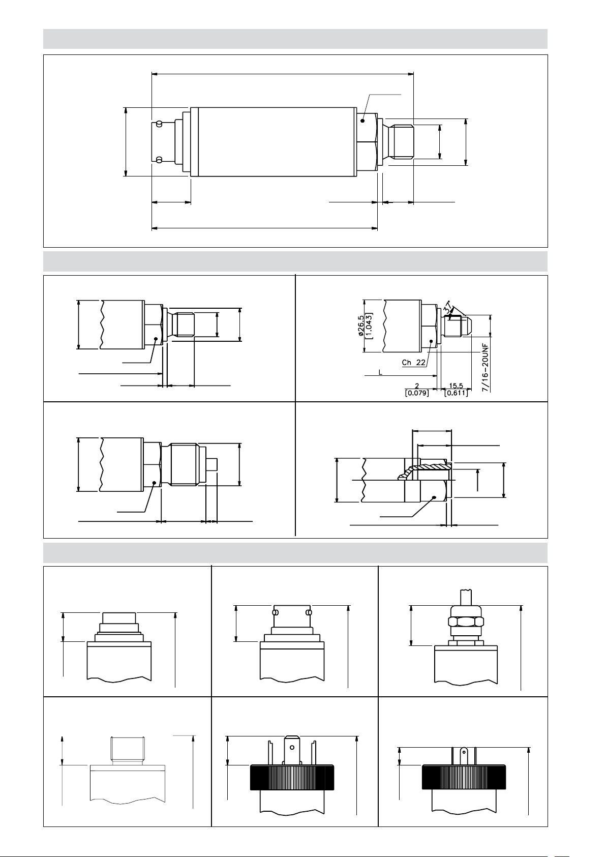
INSTALLATION DRAWINGS
Ch 22
2
[0.079]
12
[0.472]
ø 26.5
[1.043]
G 1/4
ø 18
[0.709]
L
[2.571]
ø 26.5
[1.043]
Ch 22
20
[0.787]
5
[0.197]
G 1/2
L
Ch 22
2
[0.079]
13
[0.512]
15
[0.591]
ø 26.5
[1.043]
G 1/4
ø 21
[0.827]
L+7mm
Dimensions: mm [inches]
ø 26.5
[1.043]
15
[0.591]
PRESSURE CONNECTION
(1) G 1/4 MALE (DIN 3852-A) (2) SAE 04 AS4395 - E
84
[3.307]
L=70
[2.756]
2
[0.079]
Ch 22
G 1/4
12
[0.472]
ø 18
[0.709]
(3) G 1/2 A (DIN 16288) (4) G 1/4 FEMALE
ELECTRICAL CONNECTION
P - 7 pole connector V - 6 pole connector F - 6 pole cable
17
[0.668]
11
[0.433]
L=68
[2.677]
15
[0.591]
L=70
[2.756]
L=71
[2.795]
Z - 4 pole connector
M12 x 1
10.5
[0.413]
[2.539]
L= 64.5
E - 4 pole connector
solenoid
12
[0.472]
L=70
[2.756]
M - 4 pole connector
microsolenoid
7.3
[0.287]
L=65.3
Page 3

ELECTRICAL CONNECTION - Connectors
P - 7-pole connector V - 6-pole connector
Male connettor 09-127-09-07
Protection IP67
Male connettor VPT02A10-6PT2
Protection IP66
E - 4 pole solenoid connector
M - 4 pole microsolenoid connector
Solenoid DIN 43650A - ISO4400 Protection IP65
Microsolenoid DIN 43650C - ISO4400 Protection IP65
ELECTRICAL CONNECTION - connection diagrams
mV/V output
R-Cal
POWER SUPPLY
POWER SUPPLY
Signal output
Signal output
Shunt Calibration
n.c.
Code
+
-
-
+
E - F
C
D
B
A
Z - 4 pole M12 x 1 male connector
21
34
Male connettor 4 pole series 713
Protection IP67
F - 6 pole cable
Shield
F - Shielded cable 6 x 0.25 - 1m.
V
Code
P
1
2
4
3
5 - 6
Code
F
White
Green
Black or
Yellow
Red
Blue/
Orange or Violet
Code
E/M
3
2
1
Not
available
Red
Black
White
Green
Blue
Orange
Code
Z
1
2
4
3
Not
available
7
ACCESSORIES ON REQUEST
Connectors
Connection E
3 pole connector + ground DIN43650A ISO4400 CON 006
Prot. IP65
Connection M
3 pole connector + ground DIN43650C ISO4400 CON 008
Prot. IP65
Connection Z
4 pole female cable connector M12x1 CON 293
Prot. IP67
Connection Z
4 pole female cable connector, 90° M12x1 CON 050
Prot. IP67
Connection P
7 pole female cable connector, CON 321
Prot. IP67
Connection P
7 pole female cable connector, CON 320
Prot. IP40
Connection P
7 pole female cable connector 90°, CON 322
Prot. IP40
Connection V
6 pole female cable connector, CON 300
Prot. IP66
O-ring
O-ring seal for G1/4 gas male pressure connector (1) RON 300
EXTENSION CABLES
6 pole female connector (CON 300) + 2 m (6.5 ft) of cable (6x0.25) C02W
6 pole female connector (CON 300) + 4 m (13 ft) of cable (6x0.25) C04W
6 pole female connector (CON 300) + 6 m (20 ft) of cable (6x0.25) C06W
6 pole female connector (CON 300) + 8 m (25 ft) of cable (6x0.25) C08W
6 pole female connector (CON 300) + 10 m (33 ft) of cable (6x0.25) C10W
6 pole female connector (CON 300) + 15 m (50 ft) of cable (6x0.25) C15W
6 pole female connector (CON 300) + 20 m (66 ft) of cable (6x0.25) C20W
6 pole female connector (CON 300) + 25 m (82 ft) of cable (6x0.25) C25W
6 pole female connector (CON 300) + 30 m (100 ft) of cable (6x0.25) C30W
Other lengths on request
Cable shield connected to transducer body
Cable
color code
Pin Wire
A Red
B Black
C White
D Green
E Blue
F Orange
Page 4

ORDERING INFORMATION
Pressure transducer TPS
PRESSURE CONNECTION
Standard
G 1/4 gas male
On request
7/16-20 UNF-2A male
(SAE 4 for AS4395-E)
G 1/2A (DIN 16288)
G 1/4 gas female
1/8-27 NPT female
1/4-18 NPT female
1/4-18 NPT male
M14 x 1.5 male
1/8-27 NPT male
G 1/4 male (DIN 3852-E)
M12 x 1.5 male
7/16-20 UNF-2A male
(SAE 4 for J1926-2) (*)
7/16-20 UNF-2A female
(SAE 4)
(*) Max. working pressure:
630 bar (9137 psi)
ELECTRICAL CONNECTION
4-pole connector solenoid
shielded cable
4-pole connector
4-pole connector microsolenoid
7 pole connector
6 pole connector
(*) Calibration signal not available
1
2
3
4
5
6
7
8
9
E
R
K
F
E *
F
Z
M *
P
V
Mechanical and/or electrical characteristics
differing from standard may be arranged on
request.
ACCURACY
±0.15% FSO typical >200bar/3000psi
T
±0.25% FSO typical ≤200bar/3000psi
MEASUREMENT RANGE
bar
B01D
B16U
B02D
B25U
B03D
B35U
B04D
B05D
B06D
B01C
B16D
B02C
*
B25D
B35D
B04C
B05C
B06C
B07C
B01M
0..10
0..16
0..20
0..25
0..30
0..35
0..40
0..50
0..60
0..100
0..160
0..200
0..250
0..350
0..400
0..500
0..600
0..700
0..1000
P15D
P25D
P03C
P05C
P75D
P01M
P15C
P02M
P25C
P03M
P04M
P05M
P75C
P10M
P15M
psi
0..150
0..250
0..300
0..500
0..750
0..1000
0..1500
0..2000
0..2500
0..3000
0..4000
0..5000
0..7500
0..10000
0..15000
Calibration StandardS
Instruments manufactured by Gefran are
calibrated against precision pressure
calibration equipment wich is traceable to
International Standards.
Ex.: TPS - 4 - V - B07C - T
Pressure transducer TPS with G 1/4 female process connection, 6 pole connector, 0...700 bar measurement range,
± 0.15% FSO accuracy.
GEFRAN spa reserves the right to make any kind of design or functional modification at any moment without prior notice
DTS_TPS_09-2010_ENG
 Loading...