

Page 1
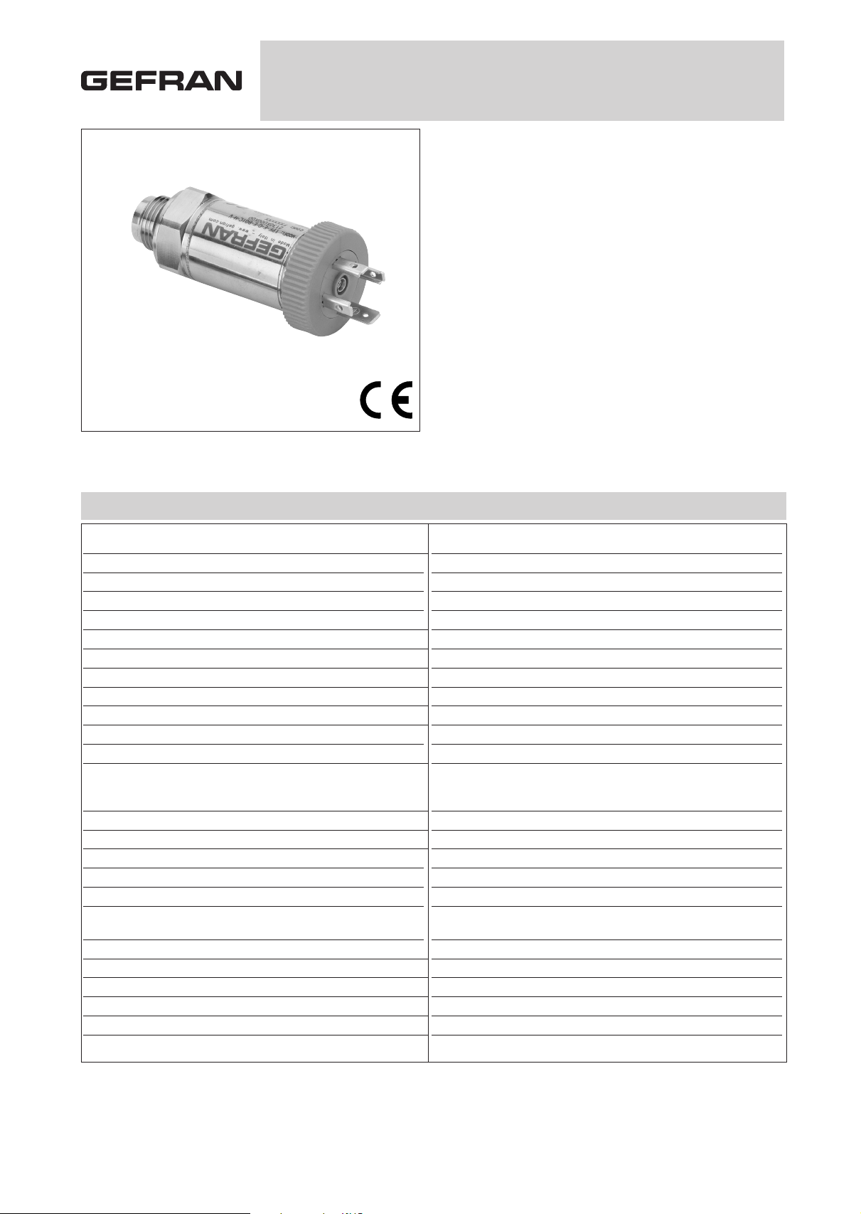
TPF
FLUSH DIAPHRAGM PRESSURE TRANSDUCER
TECHNICAL DATA
FSO = Full Scale Output (output signal at rated pressure)
1 Includes combined effects of Non-Linearity BFSL (Best Fit Straight Line), Hysteresis and Repeatability
2 tested for more than 1000 strokes with single duration < 2msec.
3 tested for more than 100 strokes with single duration < 2msec.
4 temperature outside compensated range may cause zero signal drift
5 ambient and/or electronics part temperature must not exceed 105°C
Accuracy (1)
Resolution
Overpressure (without degrading performance) (2)
Pressure containment (Burst test) (3)
Wetted parts
Body materials
Power supply
Common mode voltage
Output impedance
Load impedance
Insulation resistance
Zero offset and span setting
Output voltage (sensitivity)
Calibration signal
Long term stability
Operating temperature range (process) (5)
Compensated temperature range (4)
Storage temperature range
Temperature effects over compensated range (zero-span)
Mounting position effects
Humidity
Weight
Mechanical shock
Vibrations
Ingress protection
H ± 0.2% FSO typical (± 0.3% FSO max) 0-60...0-1000 bar
M ± 0.5% FSO typical (± 0.6% FSO max) 0-10...0-50 bar
Infinite
3 x Full Scale (max 2000 bar)
4 x Full Scale (max 2000 bar)
Fluid compatible with Inox 17-4PH
Inox AISI 304 Stainless Steel and Nylon 66GF35V0
10 (max 15) Vdc/ac RMS
Typical 5V @ 10V supply
350 Ω (±1)
> 1000 KΩ
> 1000 MΩ @ 50Volt
± 0.5% FSO
10...40 bar / 150...500 psi - 1.5 mV/V nominal
50...160 bar / 750...1500 psi - 2 mV/V nominal
200...1000 bar / 3000...15000 psi - 3 mV/V nominal
80% FSO nominal (see connection diagram)
0.2% FSO/Year
-40...+120°C (-40...+248°F)
-20...+85°C (-4...+185°F)
-40...+125°C (-40...+257°F)
± 0.01% FSO/°C typical (± 0.02% FSO/°C max.) > 50 bar (750 psi)
± 0.02% FSO/°C typical (± 0.03% FSO/°C max.) ≤ 50 bar (750 psi)
Negligible
Up to 100% HR non condensing
110 gr. nominal
100g/11msec, according to IEC 60068-2-27
20g max @ 10...2000Hz, according to IEC 60068-2-6
IP65/IP66/IP67
Internal state of the art electronics and very high precision mechanical machining make TPF product the ideal solution for above needs,
where the non amplified mV/V sensor has to be used.
Main features
• Ranges: from: 0...10 to 0...1000 bar
(0...150 to 0...15000 psi)
• Accuracy: ±0.2% FSO typical
• Protection rating: IP65/IP67
• Wetted parts: 17-4PH
• Temperature range: -40...+120°C
• Flush fitting stainless steel measuring diaphragm
• Internal calibration signal
TPF Series flush diaphragm pressure transducers are based on
bonded strain gauge on stainless steel technology.
Thanks to the strong flush diaphragm made with 17-4 PH stainless
steel, TPF is particularly suitable for pressure measurement where
the media is with high viscosity (thick fluids, oils, rubber, pulps, chemical products, etc.) and the traditional transducers with internal
measuring chamber cannot be used.
The high thickness of the diapragm makes the product very reliable
and suitable for heavy industrial application.
Page 2

MECHANICAL DIMENSIONS - Process Connections
ELECTRICAL CONNECTION
Dimensions: mm [inches]
Connection
M18 x 1.5
(code G)
Connection
3/4” - 16 UNF
(code L)
Connection
1/2” G male
(code M)
Pressure range Dimension “A” (mm) Pressure range Dimension “A” (mm) Pressure range Dimension “A” (mm)
PSI BAR M18x1.5 (G) 3/4” (L) 1/2” (M) PSI BAR M18x1.5 (G) 3/4” (L) 1/2” (M) PSI BAR M18x1.5 (G) 3/4” (L) 1/2” (M)
150 10 750 50 7500 500
250 16 1000 60 600
300 20 1500 100 10000 700 14.1 14.1 21.6
25 13 13 20.5 2500 160 13.5 13.5 21 15000 1000
30 3000 200
500 35 250
40 5000 350
400
ATTENTION: for installation use a maximum torque force of 40Nm
P - 7 pole connector V - 6 pole connector
F - 4/6 pole cable
11
[0.433]
L = 70.5
[2.776]
15
[0.591]
L = 72.5
[2.854]
17
[0.668]
L = 73.5
[2.894]
10.5
[0.413]
L = 67.0
[2.638]
12
[0.472]
L = 72.5
[2.854]
7.3
[0.287]
L = 68.0
[2.677]
Z - 4 pole connector
M12 x 1
E - 4 pole connector
solenoid
M - 4 pole connector
microsolenoid
Page 3

ELECTRICAL CONNECTION - Connectors
P - 7 pole connector V - 6 pole connector
Male connector 09-127-09-07
Protection IP67
4 pole series 713 male connector
Protection IP67
Z - 4 pole male connec-
tor M12 x 1
Male connector VPT02A10-6PT2
Protection IP66
Solenoid DIN 43650A - ISO4400
Protection IP65
Microsolenoid DIN 43650C - ISO4400
Protection IP65
E - 4 pole solenoid connector
M - 4 pole microsolenoid connector
Shielded cable 6x0.25 - 1m
Protection IP65
ELECTRICAL CONNECTION - connection diagram
Shield
Orange
Blue
Red
Black
White
Green
F - 6 pole cable
mV/V output
Code
V
Code
P
C
D
B
A
E - F
1
2
4
3
5 - 6
7
n.c.
Power supply
+
+
Signal output
Shunt Calibration
Power supply
-
-
Signal output
Cable shield connected to transducer body
R-Cal
Code
F
White
green
Red
Blue /
Orange or
Violet
Code
E/M
3
2
1
Non
available
Code
Z
1
2
4
3
Non
available
Black or
Yellow
ACCESSORIES ON REQUEST
Connectors
Connection E
3 pole connector + ground DIN43650A ISO4400 CON 006
Prot. IP65
Connection M
3 pole connector + ground DIN43650C ISO4400 CON 008
Prot. IP65
Connection Z
4 pole female cable connector M12x1 CON 293
Prot. IP67
Connection Z
4 pole female cable connector, 90° M12x1 CON 050
Prot. IP67
Connection P
7 pole female cable connector, CON 321
Prot. IP67
Connection P
7 pole female cable connector, CON 320
Prot. IP40
Connection P
7 pole female cable connector 90°, CON 322
Prot. IP40
Connection V
6 pole female cable connector, CON 300
Prot. IP66
EXTENSION CABLES
6 pole female connector (CON 300) + 2 m (6.5 ft) of cable (6x0.25) C02W
6 pole female connector (CON 300) + 4 m (13 ft) of cable (6x0.25) C04W
6 pole female connector (CON 300) + 6 m (20 ft) of cable (6x0.25) C06W
6 pole female connector (CON 300) + 8 m (25 ft) of cable (6x0.25) C08W
6 pole female connector (CON 300) + 10 m (33 ft) of cable (6x0.25) C10W
6 pole female connector (CON 300) + 15 m (50 ft) of cable (6x0.25) C15W
6 pole female connector (CON 300) + 20 m (66 ft) of cable (6x0.25) C20W
6 pole female connector (CON 300) + 25 m (82 ft) of cable (6x0.25) C25W
6 pole female connector (CON 300) + 30 m (100 ft) of cable (6x0.25) C30W
Other lengths on request
Cable
color code
Pin Wire
ARed
B Black
C White
D Green
E Blue
F Orange
21
34
Page 4

GEFRAN spa reserves the right to make any kind of design or functional modification at any moment without prior notice
DTS_TPF_0108_ENG
ORDERING INFORMATION
Pressure Transducer TPF
PROCESS CONNECTION
M18x1.5
Standard
G
1/2” G male M
3/4-16 UNF
On request
L
ELECTRICAL CONNECTION
6 pole connector V
7 pole connector P
M12x1 connector (*) Z
6 pole shielded cable (**) F
4 pole solenoid connector (*) E
4 pole microsolenoid
connector (*)
M
(*) Calibration signal not available
(**) 1mt cable included as standard. Custom lengths available,
at extra cost.
Mechanical and/or electrical characteristics differing from standard may be
arranged on request.
H
±0.2%FS typical
0...60 - 0...1000 bar (only)
ACCURACY
M
±0.5%FS typical
0...10 - 0...50 bar ( only)
MEASUREMENT RANGE
B01D 0...10 P15D 0...150
Bar Psi
B16U 0...16 P25D 0...250
B02D 0...20 P03C 0...300
B25U 0...25 P05C 0...500
B03D 0...30 P75D 0...750
B35U 0...35 P01M 0...1000
B04D 0...40 P15C 0...1500
B05D 0...50 P02M 0...2000
B06D 0...60 P25C 0...2500
B01C 0...100 P03M 0...3000
B16D 0...160 P04M 0...4000
B02C 0...200 P05M 0...5000
B25D 0...250 P75C 0...7500
B35D 0...350 P10M 0...10000
B04C 0...400 P15M 0...15000
B05C 0...500
B06C 0...600
B07C 0...700
B01M 0...1000
Ex.: TPF - G - P - B01D - M - -
Flush fitting pressure transducer, M18x1.5 process connection, 7 pole electrical connector, 0...10 bar measurement range, ±0.5%FSO typical accuracy.
CALIBRATION STANDARDS
Instruments manufactured by Gefran are
calibrated against precision pressure calibration equipment wich is traceable to
International Standards
Standard
 Loading...