

Page 1
TC
LOAD CELL FOR TENSION/COMPRESSION
APPLICATIONS
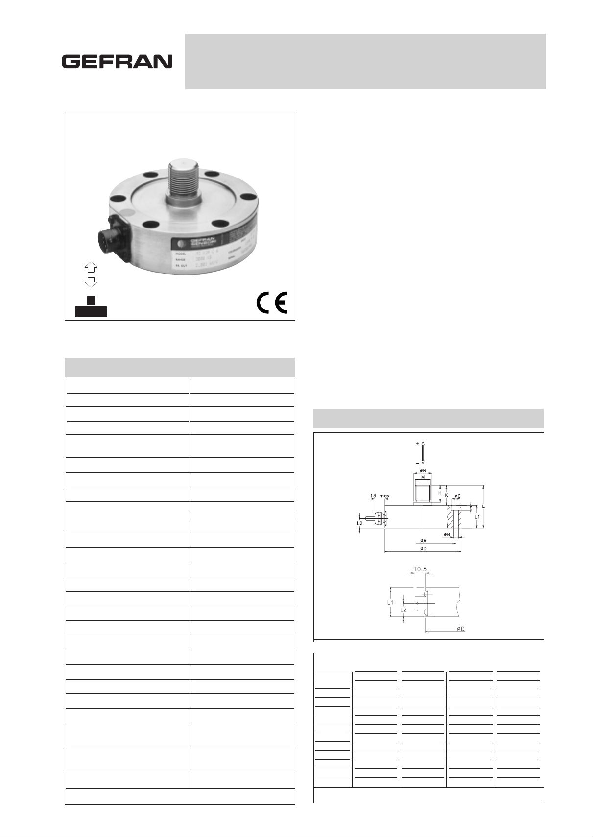
MECHANICAL DIMENSIONS
Main features
• Range of measurement: from100 to 20.000 Kg
• Accuracy class: 0,2%
• All stainless steel construction
• Corrosion resistant
• Internally generated calibration signal
• Grade of protection: IP67 (DIN 40050)
TC series load cells are strain gauge transducers used to
measure loads in static and dynamic applications, in tension
(positive signal of output) and compression (negaitive signal
of output), with high accuracy (industrial weighing, laboratory
testing, automation, etc).
The TC series is machined from a single block of metal, so
the primary sensing element, the mountings and the case
contain no welds allowing smaller dimensions and an enhanced grade of protection.
The configuration of the point of measurement, with 8 strain
gauges, reduces errors caused by imperfect application of the
load.Typical applications of load cells connected in parallel
are: silos, hoppers, large weighing platforms, and with suitable accessories, suspended loads. The stainless steel construction is suitable for use in aggressive environments in the
chemical and petrochemical industries.
ø A
ø B
ø C
ø D
E
H
K
L
L1
L2
M
ø N
wires
100
2000
87
6,5
10,5
100
6
21
25
55
30
13,5
M20x1,5
24
6xM6
3500
5000
98,5
10,5
16,5
120
10
33,6
37,6
67,6
30
13,5
M24x2
30
6xM10
7000
10000
125
13
19
155
12,5
45
50
90
40
20
M39x3
45
8xM12
20000
135
17
25
170
21
65
70
131
61
27
M52x3
55
8xM16
Ln (Kg)
Dimensions mm. (± 0,1)
TECHNICAL DATA
0,2%
100...20.000 Kg
2mV/V
<± 0,2% FSO
< ± 0,2% FSO
< ± 0,06% FSO
< ± 1% FSO
80%FSO ± 1%
< ± 0,01% FSO°C
< ± 0,01% FSO°C
< ± 0,01% FSO°C
700 Ohm
700 Ohm
> 10 GOhm
10 V
15 V
-10...+50°C
-20...+60°C
-30...+80°C
130% Ln
100% Ln
150% Ln
> 300% Ln
< 0,2 mm
Cable IP67
Connector IP65
VPT02A10-6PT2
6x0,25 / 5 m.
Stainless steel
Accuracy
Nominal full scale load (Ln)
Nominal output at FSO
Output tolerance at Ln
Combined errors: Non linearity
Histeresis, Repeatibility
Creep (after 30 min. at Ln)
Zero load out of balance signal
Calibration signal *
Thermal drift in Sensitivity
compensated Zero
range Calibration
Nominal input resistance
Nominal output resistance
Isolation resistance
Nominal supply voltage
Maximum supply voltage
Compensated temperature range
Maximum temperature range
Storage temperature range
Permitted static load
Permitted dinamic load
Maximum applicable load
Rupture load
Maximum elastic deformation at Ln
Grade of protection (DIN40050)
Electr. connections: Connector
Screened cable
Elastic element material
* The exact value is indicated on the instrument nameplate.
LOAD
INTRODUCTION
DIRECTION
Page 2
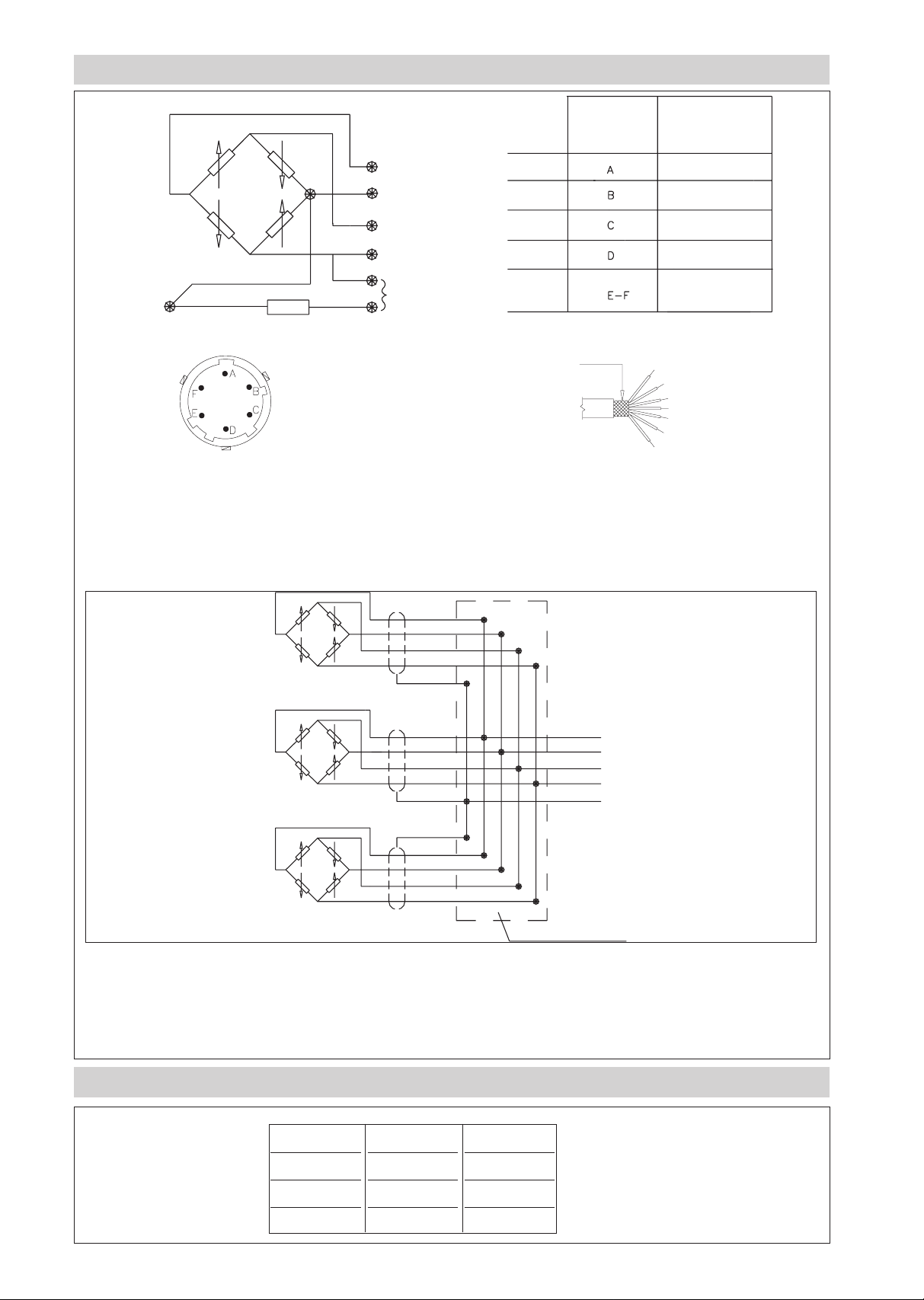
ELECTRICAL CONNECTIONS
CONVERSION TABLE
If the transducer is supplied complete with
prewired connection cable, the colour code is that
indicated in the table.
Cells connected in parallel
In systems that use several cells, the parallel connection automatically sums the loads on each individual cell.
Using this method of measurement, the maximum load will be the sum of the loads on the individual cells and the
sensitivity will be the average value of these cells.
It is important that the user ensures that no cell is stessed beyond its maximum rating under any load condition.
Kg
1
0.102
0.454
N
9.807
1
4.448
Lb
2.205
0.225
1
* The screen is isolated from the transducer body.
It is recommended that the screen is connected to
ground at the instrument end.
6x0.25 Screened cable
NB.: The output signal is positive for traction loads and for calibration, and negative for compression loads.
VPT02A10-6PT2
CONNECTOR
CONNECTOR
OUTPUT
SIGNAL +
SIGNAL EXCITATION +
EXCITATION -
CALIBRATION SHUNT
Shield *
CABLE
OUTPUT
Red
Black
White
Green
Blue-Orange
Red
Black
White
Green
Blue
Orange
Yellow or green
Red
Yellow or Black
White
Green
Yellow-Green
Red
Yellow or Black
White
Green
Yellow-Green
Yellow-Green
Red
Yellow or Black
White
Green
SHUNT BOX
Page 3

GEFRAN spa reserves the right to make any kind of design or functional modification at any moment without prior notice.
ORDER CODE
Ex.: TC - K10M - F - S
TC load cell, measurement range 0 - 10.000 kg, cable connection and 2mV/V standard sensitivity.
SENSITIVITY
2mV/V Version
S
ELECTR. CONNECTIONS
VPT02A10-6PT2 Connect.
C
If request, it is possible to supply models with non-standard
mechanical and/or electrical
features.
Load cell TC
0 - 500 K5C
0 - 350 K3.5C
MEASUREMENT RANGE (Kg)
0 - 100
0 - 200
K1C
K2C
0 - 700 K7C
6x0,25 5m screened cable
OPTIONAL ACCESSORIES
Female cable connector Grade of protection IP65 CON 300
6-pin connector with 8m (25ft) cable C08W
6-pin connector with 15m (50ft) cable C15W
6-pin connector with 25m (75ft) cable C25W
6-pin connector with 30m (100ft) cable C30W
Other lengths consult factory
Flange and ball joint see table
0 - 1000 K1M
F
3mV/V Version
(range 500...5000Kg)only
R
0 - 2000 K2M
0 - 3500 K3.5M
0 - 5000 K5M
0 - 7000 K7M
0 - 10000 K10M
0 - 20000 K20M
APPLICATION NOTES
Nominal
load
100 - 700
1000 - 2000
3500 - 5000
7000 - 10000
20000
M1*
(Nm)
60
300
500
2500
4500
M2**
(Nm)
20
20
90
125
300
Flange
code
FLA700
FLA700
FLA701
FLA702
FLA704
Locknut
recommended
-
M24x2-h=10
M39x3-h=16
M52x3-h=20
* Recommended tightening torque between ball-joint and locknut or flange
**Recommended tightening torque with UNI5931 screws with 10.9 resistance
class according to UNI3740
Joint
code
SND020
SND020
SND024
SND040
SND060
Locknut
Flange
Joint
Joint
NO LOAD ON
THIS SURFACE
NO LOAD ON
THIS SURFACE
Joint
Locknut
Flange
mounting for
suspended
loads
Wall
mounting
Cable colour code
Conn. wires
A
B
C
D
E
F
Red
Black
White
Green
Blue
Orange
DTS_TC_0709_ENG
 Loading...