

gefran SIEIDrive AVy Series, SIEIDrive AVy71100, SIEIDrive AVy71320, SIEIDrive AVy6750, SIEIDrive AVy7900 Quick Start Up Manual
...Page 1
V ector AC Drives
SIEIDrive
AVy
...Quick start up guide
Specification and installation
Page 2

Thank you for choosing this Gefran product.
We will be glad to receive any possible information which could help us improving
this manual. The e-mail address is the following: techdoc@gefran.com.
Before using the product, read the safety instruction section carefully.
Keep the manual in a safe place and available to engineering and installation personnel during the product functioning period.
Gefran S.p.A has the right to modify products, data and dimensions without notice.
The data can only be used for the product description and they can not be understood as legally stated properties.
All rights reserved
This manual is updated according the software version V1.X00.
Variation of the number replacing “X” have no influence on the functionality of the
device.
The identification number of the software version can be read on the inverter nameplate or on the label on the FLASH memories mounted on the regulation card.
2
Page 3

Table of Contents
Safety symbol legend ...........................................................................................................................8
0. SAFETY PRECAUTIONS - PRECAUTIONS DE SECURITÉ .......................................9
1. QUICK START UP GUIDE ......................................................................................13
1.1. FUNCTIONAL CONNECTION DIAGRAM .................................................................................. 13
1.2. OVERVIEW.............................................................................................................................. 14
1.3. CONTROL TERMINALS............................................................................................................ 15
1.3.1 Maximum cable cross section for regulator terminals....................................................... 16
1.4. POWER TERMINALS............................................................................................................... 16
Figure 1.4.1: Power Terminals connection....................................................................................... .........16
1.4.1 Maximum cable cross section for power terminals........................................................... 16
1.5 ENCODER TERMINALS (XE CONNECTOR)................................................................................ 17
1.5.1 Encoder type connection .................................................................................................. 17
1.5.2 Jumpers setting................................................................................................................ 18
1.5.3 Maximum cable length for encoder terminals ................................................................... 18
1.6. LIST OF JUMPERS AND DIP-SWITCH ..................................................................................... 19
1.7. KEYBOARD OPERATION .......................................................................................................... 20
1.7.1 LEDs & buttons................................................................................................................. 20
1.7.2 Moving inside a menu ......................................................................................................22
1.8. PRE POWER CHECKS.............................................................................................................. 23
1.9. QUICK TUNING........................................................................................................................ 24
1.9.1 Motor Potentiometer..................................................................................................................27
1.10 OPTIONAL THINGS ................................................................................................................ 28
1.11 QUICK TUNING GUIDE FOR FACTORY CONFIGURED (OR PRE-CONFIGURED) DRIVES ........... 29
1.12 TROUBLESHOOTING .............................................................................................................. 30
Overflow list .......................................................................................................................................30
LIST OF SELF TUNE ERROR MESSAGES.................................................................................... 31
Failure alarms in the keypad display.......................................................................................... 32
Other faults ............................................................................................................................... 34
2. FUNCTION AND FEATURE (OVERVIEW) ..............................................................3 7
3. INSPECTION PROCEDURE, COMPONENT IDENTIFICATION AND STANDARD
SPECIFICATION ....................................................................................................39
3.1. UPON DELIVERY INSPECTION PROCEDURES .......................................................................... 39
3.1.1. General ........................................................................................................................... 39
3.1.2. Inverter type designation................................................................................................ 39
3.1.3. Nameplate ...................................................................................................................... 40
Figure 3.1.3.1: Identification nameplate ..................................................................................................40
Figure 3.1.3.2: Firmware & Card revision level nameplate .......................................................................40
Figure 3.1.3.3: Nameplates position.........................................................................................................40
3.2. COMPONENT IDENTIFICATION .............................................................................................. 41
Figure 3.2.1: Basic Setup of Frequency Inverter......................................................................................41
Figure 3.2.2: Drive view & components....................................................................................................42
3
Page 4

3.3. STANDARD SPECIFICATIONS ................................................................................................. 43
3.3.1. Permissible environmental conditions.............................................................................. 43
Table 3.3.1.1: Environmental specification ...............................................................................................43
Disposal of the Device ........................................................................................................................44
3.3.2. AC Input/Output Connection ........................................................................................... 44
Table 3.3.2.1:AC Input/Output specifications............................................................................................45
3.3.3. AC Input current ............................................................................................................. 46
3.3.4. AC Output........................................................................................................................ 46
Table 3.3.3.1: Nominal Drive Current .......................................................................................................47
3.3.5. Open-Loop and Closed-Loop Control Section ................................................................... 48
3.3.6. Accuracy......................................................................................................................... 49
4. INSTALLATION GUIDELINES ................................................................................51
4.1. MECHANICAL SPECIFICATION................................................................................................ 51
Figure 4.1.1: Drive dimensions (sizes 1007 ... 3150)................................................................................51
Figure 4.1.2: Mounting methods (sizes 1007 ... 3150) .............................................................................51
Table 4.1.1: Drive dimensions and Weights (sizes 1007 ... 3150).............................................................51
Figure 4.1.3: Drive dimensions (sizes 4185 ... 82000).............................................................................52
Figure 4.1.4: Mounting methods (sizes 4185 ... 82000) ...........................................................................52
Table 4.1.2: Drive dimensions and Weights (sizes 4185 ... 82000)..........................................................52
Figure 4.1.5: Keypad positioning ..............................................................................................................53
4.2. WATTS LOSS, HEAT DISSIPATION, INTERNAL FANS AND MINIMUM CABINET OPENING
SUGGESTED FOR THE COOLING .................................................................................................... 53
Table 4.2.1: Heat dissipation and Required Air Flow ................................................................................53
Table 4.2.2: Minimum cabinet opening suggested for the cooling............................................................53
4.2.1 Cooling fans power supply ............................................................................................... 54
Figure 4.2.1: UL type fans connections on AVy7900, AVy71100 and AVy71320 sizes..............................54
Figure 4.2.2: UL type fans connections on AVy6750 and AVy82000 sizes................................................54
Figure 4.2.3: Example for external connection..........................................................................................54
4.3. INSTALLATION MOUNTING CLEARANCE................................................................................ 55
Figure 4.3.1: Max. Angle of Inclination.....................................................................................................55
Figure 4.3.2: Mounting Clearance............................................................................................................55
4.4. MOTORS AND ENCODERS...................................................................................................... 56
4.4.1. Motors ............................................................................................................................ 56
4.4.2. Encoder........................................................................................................................... 57
Table 4.4.2.1: Recommended cable section and length for the connection of encoders...........................57
Table 4.4.2.2: Encoders setting via S11...S23 jumpers.............................................................................58
Table 4.4.2.3: Encoders connections........................................................................................................58
Table 4.4.2.4: Assignment of the high density XE connector for a sinusoidal or a digital encoder ............60
5. WIRING PROCEDURE ...........................................................................................6 1
5.1. ACCESSING TO THE CONNECTORS ........................................................................................ 61
5.1.1 Removing the Covers........................................................................................................ 61
Figure 5.1.1: Removing the covers (sizes 1007 to 3150)..........................................................................61
Figure 5.1.2: Removing the covers (sizes 4220 to 82000)........................................................................62
5.2. POWER SECTION.................................................................................................................... 63
5.2.1. PV33-.. Power card ......................................................................................................... 63
Figure 5.2.1.1: PV33-1-. power card (sizes 1007 to 1030) .......................................................................63
Figure 5.2.1.2: PV33-2-.. power card (sizes 2040 to 2075) ......................................................................63
Figure 5.2.1.3: PV33-3-.. power card (sizes 3110 and 3150) ...................................................................64
Figure 5.2.1.4: PV33-4-.. power card (sizes 4220 to 5550) ......................................................................64
4
Page 5

Figure 5.2.1.5: PV33-5-.. power card (sizes 6750 to 71320) ....................................................................65
Figure 5.2.1.6: PV33-6-.. power card (sizes 81600 to 82000) ..................................................................65
5.2.2. Terminal Assignment on Power section / Cable Cross-Section......................................... 66
Figure 5.2.2.1: Power Terminals connection.............................................................................................66
Table 5.2.2.1: Maximum cable cross section for power terminals..........................................................66
5.3. REGULATION SECTION ........................................................................................................... 67
5.3.1 RV33 Regulation Card ......................................................................................................67
Figure 5.3.1.1: RV33-4 Regulation Card Switch & Jumpers.....................................................................67
Table 5.3.1.1: LEDs & Test points on Regulation card ...............................................................................67
Table 5.3.1.3: Jumpers on Regulation Card RV33-3 .................................................................................68
Table 5.3.1.4: RV33 Regulation Card Switch S3 Settings .........................................................................68
5.3.2. Terminal Assignments on regulation section .................................................................... 69
Table 5.3.2.1: Plug-in Terminal Strip Assignments....................................................................................69
Table 5.3.2.2: Maximum permissible cable cross- section on the plug-in terminals of the regulator section .
................................................................................................................................................................70
Table 5.3.2.3: Maximum Control Cable Lengths .......................................................................................70
Figure 5.3.1.2: Potentials of the control section, Digital I/O NPN connection ...........................................71
5.4. SERIAL INTERFACE................................................................................................................. 72
5.4.1. Serial Interface Description .............................................................................................72
Figure 5.4.1.1: RS485 Serial Interface .....................................................................................................72
5.4.2. RS 485 Serial Interface Connector Description ................................................................ 73
Table 5.4.2.1: Assignment of the plug XS connector for the RS 485 serial interface.................................73
5.5. STANDARD CONNECTION DIAGRAM ..................................................................................... 74
5.5.1. AVy Connections ............................................................................................................. 74
Figure 5.5.1.1:Control sequencing............................................................................................................74
Figure 5.5.1.2: Typical connection............................................................................................................75
5.5.2. Parallel Connection on the AC (Input) and DC (Intermediate Circuit) Side of Several
Inverters.................................................................................................................................... 76
Figure 5.5.2.1: Parallel Connection on the AC and DC Side of Several Inverters ......................................76
5.6. CIRCUIT PROTECTION............................................................................................................. 77
5.6.1. External fuses of the power section................................................................................. 77
Table 5.6.1.1: External Fuse Types for AC input side ................................................................................77
5.6.2. External fuses of the power section DC input side ........................................................... 78
Table 5.6.2.1: External fuses type for DC input side..................................................................................78
5.6.3. Internal fuses .................................................................................................................. 78
Table 5.6.3.1: Internal fuses .....................................................................................................................78
5.7. CHOKES / FILTERS .................................................................................................................. 79
5.7.1. AC Input Chokes.............................................................................................................. 79
Table 5.7.1.1:3-Phase AC Input Chokes....................................................................................................79
5.7.2. Output Chokes................................................................................................................. 79
Table 5.7.2.1: Recommended values for output chokes............................................................................80
5.7.3. Interference Suppression Filters ...................................................................................... 80
5.8. BRAKING UNITS ..................................................................................................................... 81
Figure 5.8.1: Operation with Braking Unit (Principle)................................................................................81
5.8.1. Internal braking unit ........................................................................................................ 81
Figure 5.8.1.1: Connection with internal Braking Unit and external braking resistor.................................81
5.8.2 External braking resistor................................................................................................... 82
Table 5.8.2.1: Lists and technical data of the external standard resistors for inverters AVy1007 to 5550 82
Figure 5.8.2.2: Limit operating braking cycle with typical triangular power profile...................................82
Figure 5.8.2.2: Braking cycle with TBR / TC = 20%.................................................................................83
Figure 5.8.2.3:Generic braking cycle with triangular profile .....................................................................84
5
Page 6

Table 5.8.2.2: Braking thresholds for different Mains ..............................................................................85
Table 5.8.2.3: Technical data of the internal braking units ........................................................................85
5.8.3. Calculation of generic external braking resistor to be combined with the internal braking
unit with an approximate method .............................................................................................. 86
Figure 5.8.3.1: Power Resistor Overload Factor.......................................................................................86
5.9. BUFFERING THE REGULATOR SUPPLY.................................................................................... 87
Table 5.9.1: DC Link Buffer Time .............................................................................................................87
Figure 5.9.1: Buffering the Regulator Supply by Means of Additional Intermediate Circuit Capacitors .....87
5.10. AVY POWER DIP RIDE THROUGH DATA AND RESTART SETUP............................................. 89
Table 5.10.1: Drive Trip Times, 230-V Threshold.......................................................................................90
Table 5.10.2: Drive Trip Times, 400-V Threshold.......................................................................................91
Table 5.10.3: Drive Trip Time, 460-V Threshold ........................................................................................91
5.11. DISCHARGE TIME OF THE DC-LINK....................................................................................... 92
Table 5.11.1: DC Link Discharge Times ....................................................................................................92
6. MAINTENANCE ....................................................................................................93
6.1. CARE ...................................................................................................................................... 93
6.2. SERVICE................................................................................................................... ............... 93
6.3. REPAIRS.................................................................................................................................. 93
6.4. CUSTOMER SERVICE .............................................................................................................. 93
Block diagram legend................................................................................................................ 94
7. BLOCK DIAGRAM .................................................................................................9 5
AVy Inverter Overview........................................................................................................................95
Digital inputs/Outputs & Mapping Standard and Option cards.............................................................96
Analog Inputs/Outputs & Mapping......................................................................................................97
Speed Reference generation ...............................................................................................................98
Speed / T orque regulation ...................................................................................................................99
Ramp reference Block.......................................................................................................................100
Speed regulator.................................................................................................................................101
Speed regulator PI part .....................................................................................................................102
Droop compensation.........................................................................................................................103
Inertia / Loss compensation..............................................................................................................104
T orque current regulator....................................................................................................................105
Speed Feedback ...............................................................................................................................106
Motor control....................................................................................................................................107
Motor parameters.............................................................................................................................108
Sensorless parameters .....................................................................................................................109
V/Hz functions...................................................................................................................................110
Speed Threshold / Speed control ......................................................................................................111
Speed adaptive and Speed zero logic................................................................................................112
PID function ......................................................................................................................................113
Start and Stop management .............................................................................................................114
Power loss stop control ....................................................................................................................115
Jog function......................................................................................................................................116
Motor potentiometer.........................................................................................................................117
Multi speed.......................................................................................................................................118
Dual Motor setup ..............................................................................................................................119
Brake unit function............................................................................................................................120
DC Braking function ..........................................................................................................................121
Dimension factor / Face value factor.................................................................................................122
P AD parameters................................................................................................................................123
6
Page 7

Links function ...................................................................................................................................124
T est Generator ..................................................................................................................................125
Alarm mapping .................................................................................................................................126
8. PARAMETERS LIST ............................................................................................1 27
EMC DIRECTIVE......................................................................................................154
7
Page 8

Safety symbol legend
WARNING! Commands attention to an operating procedure, practice, condition, or statement which,
if not strictly observed, could result in personai injury or death.
CAUTION! Commands attention to an operating procedure, practice, condition, or statement which,
if not strictly observed, could result in damage or destruction of equipment.
The seriousness of the injuries and of the damages which could be caused by the nonobservance of such indications, depends on the different conditions. Anyway, the
instructions given below should always be followed with the highest attention.
NOTE! Commands attention to an operating procedure, practice, condition, or statement that
must be highlighted.
8
Page 9

0. SAFETY PRECAUTIONS - PRECAUTIONS DE SECURITÉ
ATTENTION!
According to the EEC standards the AVy and accessories
must be used only after checking that the machine has been
produced using those safety devices required by the 89/
392/EEC set of rules, as far as the machine industry is
concerned.
Drive systems cause mechanical motion. It is the
responsibility of the user to insure that any such motion
does not result in an unsafe condition. Factory provided
interlocks and operating limits should not be bypassed or
modified.
Selon les normes EEC, les drives A Vy et leurs accessoires
doivent être employés seulement après avoir verifié que
la machine ait été produit avec les même dispositifs de
sécurité demandés par la réglementation 89/392/EEC
concernant le secteur de l’industrie.
Les systèmes provoquent des mouvements mécaniques.
L’utilisateur est r esponsable de la sécurité concernant les
mouvements mécaniques. Les dispositifs de sécurité
prévues par l’usine et les limitations operationelles ne
doivent être dépassés ou modifiés.
WARNING - ELECTRICAL SHOCK AND BURN HAZARD /
ATTENTION – DÉCHARGE ÉLECTRIQUE ET RISQUE DE
BRÚLURE :
When using instruments such as oscilloscopes to work on
live equipment, the oscilloscope’s chassis should be
grounded and a differential amplifier input should be used.
Care should be used in the selection of probes and leads
and in the adjustment of the oscilloscope so that accurate
readings may be made. See instrument manufacturer’s
instruction book for proper operation and adjustments to
the instrument.
Lors de l’utilisation d’instruments (par example
oscilloscope) sur des systémes en marche, le chassis de
l’oscilloscope doit être relié à la terr e et un amplificateur
différentiel devrait êtr e utilisé en entrée.
Les sondes et conducteurs doivent être choissis avec soin
pour effectuer les meilleures mesures à l’aide d’un
oscilloscope.
V oir le manuel d’instruction pour une utilisation corr ecte
des instruments.
WARNING - FIRE AND EXPLOSION HAZARD / ATTENTION
– RISQUE D’INCENDIES ET D’EXPLOSIONS:
Fires or explosions might result from mounting Drives in
hazardous areas such as locations where flammable or
combustible vapors or dusts are present. Drives should be
installed away from hazardous areas, even if used with
motors suitable for use in these locations.
L’utilisation des drives dans des zônes à risques (présence
de vapeurs ou de poussières inflammables), peut
provoquer des incendies ou des explosions. Les drives
doivent être installés loin des zônes dangeureuses, et
équipés de moteurs appropriés.
WARNING - STRAIN HAZARD / ATTENTION À
L’ÉLÉVATION:
Improper lifting practices can cause serious or fatal injury.
Lift only with adequate equipment and trained personnel.
Une élévation inappropriée peut causer des dommages
sérieux ou fatals. Il doit être élevé seulement avec des
moyens appropriés et par du personnel qualifié.
ATTENTION – CAS DE DECHARGE ELECTRIQUE:
Drives and motors must be ground connected according
to the NEC.
Tous les moteurs et les drives doivent être mis à la terre
selon le Code Electrique National ou équivalent.
WARNING / ATTENTION:
Replace all covers before applying power to the Drive.
Failure to do so may result in death or serious injury.
Remettre tous les capots avant de mettre sous tension le
drive. Des erreurs peuvent pr ovoquer de sérieux accidents
ou même la mort.
WARNING / ATTENTION:
Adjustable frequency drives are electrical apparatus for
use in industrial installations. Parts of the Drives are
energized during operation. The electrical installation and
the opening of the device should therefore only be carried
out by qualified personnel. Improper installation of motors
or Drives may therefore cause the failure of the device as
well as serious injury to persons or material damage.
Drive is not equipped with motor overspeed protection
logic.
Follow the instructions given in this manual and observe
the local and national safety regulations applicable.
Les drives à fréquence variable sont des dispositifs
électriques utilisés dans des installations industriels. Une
partie des drives sont sous tension pendant l’operation.
L’installation électrique et l’ouverture des drives devrait
être executé uniquement par du personel qualifié. De
mauvaises installations de moteurs ou de drives peuvent
provoquer des dommages materiels ou blesser des
personnes. Le convertisseur n’est pas pourvu de protection
contre vitesse de fuite du moteur.
On doit suivir les instructions donneés dans ce manuel et
observer les régles nationales de sécurité.
—————— Quick Start up ——————
9
QS
Page 10
WARNING! - POWER SUPPLY AND GROUNDING /
ATTENTION ! ALIMENTATION PUISSANCE ET MISE À
LA TERRE
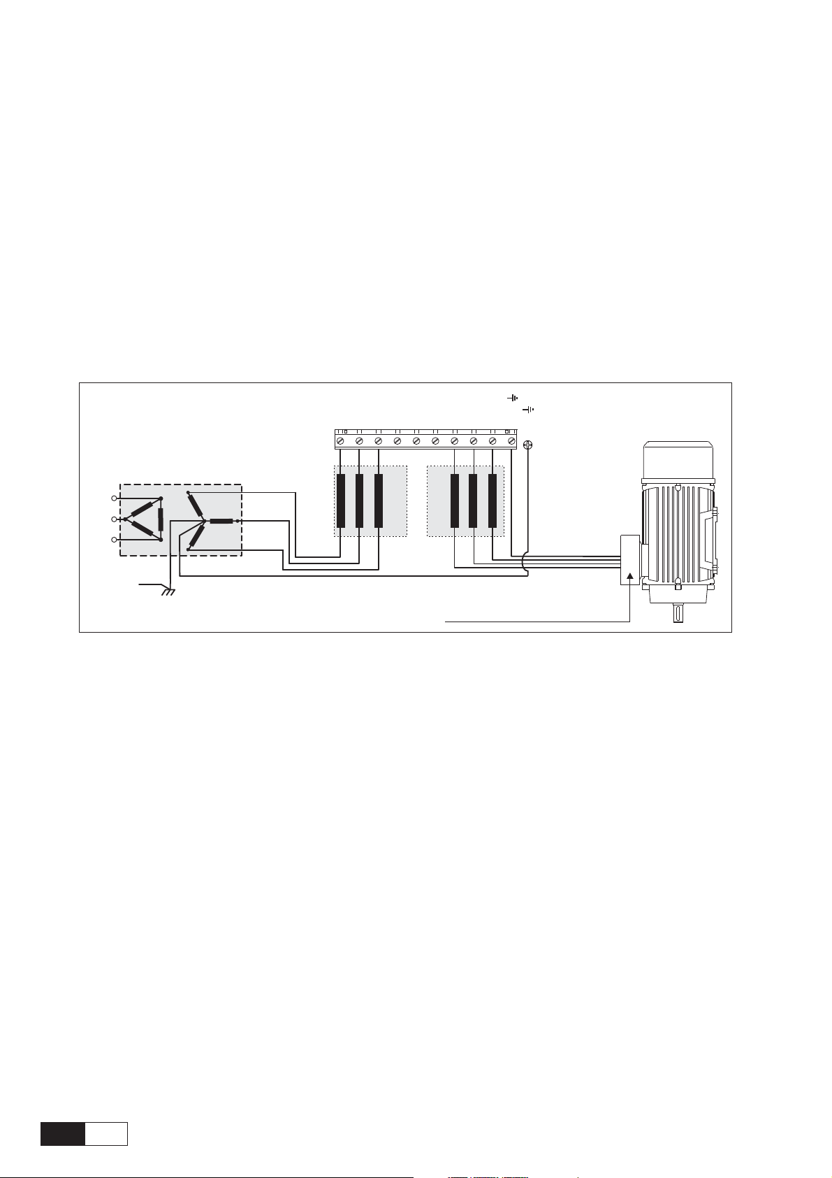
In case of a three phase supply not symmetrical to ground,
an insulation loss of one of the devices connected to the
same network can cause functional problem to the drive,
if the use of a delta /star transformer is avoided.
1 The drives are designed to be powered from standard
three phase lines that are electrically symmetrical with
respect to ground (TN or TT network).
2 In case of supply with IT network, the use of wye/delta
transformer is mandatory, with a secondary three phase
wiring referred to ground.
Please refer to the following connection sample.
U1/L1
V1/L2
W1/L3
L1
Si le réseau n'est pas équilibré par rapport à la terre et
qu'il n'y a pas de transformateur raingle/étoile, une
mauvaise isolation d'un appareil électrique connecté au
même réseau que le variateur peut lui causer des troubles
de fonctionnement.
1 Les variateurs sont prévus pour être alimentés par un
réseau triphasé équilibré avec un régime de neutre
standard (TN ou TT).
2 Si le régime de neutre est IT , nous vous r ecommendons
d'utiliser un tranformateur triangle/étoile avec point
milieu ramené à la terre
Vous pouvez trouver ci-après des exemples de câblage.
U2/T1
V2/T2
W2/T3
PE2/
PE1/
AC Main Supply
Safety
ground
L2
L3
Earth
CHOKE
AC INPUT
CHOKE
AC OUTPUT
All wires (including motor ground) must
be connected inside the motor terminal box
QS
10
AVy -HGB
Page 11

CAUTION / PRECAUTION:
Do not connect power supply voltage that exceeds the
standard specification voltage fluctuation permissible. If
excessive voltage is applied to the Drive, damage to the
internal components will result.
Ne pas raccorder de tension d’alimentation dépassant la
fluctuation de tension permise par les normes. Dans le
cas d’ une alimentation en tension excessive, des
composants internes peuvent être endommagés.
CAUTION / PRECAUTION:
Do not operate the Drive without the ground wire
connected. The motor chassis should be grounded to earth
through a ground lead separate from all other equipment
ground leads to prevent noise coupling.
The grounding connector shall be sized in accordance with
the NEC or Canadian Electrical Code. The connection
shall be made by a UL listed or CSA certified closed-loop
terminal connector sized for the wire gauge involved. The
connector is to be fixed using the crimp tool specified by
the connector manufacturer.
Ne pas faire fonctionner le drive sans prise de terre. Le
chassis du moteur doit être mis à la terre à l’aide d’un
connecteur de terre separé des autr es pour éviter le couplage
des perturbations. Le connecteur de terre devrait être
dimensionné selon la norme NEC ou le Canadian Electrical
code. Le raccordement devrait être fait par un connecteur
certifié et mentionné à boucle fermé par les normes CSA et
UL et dimensionné pour l’épaisseur du cable correspondant.
Le connecteur doit être fixé a l’aide d’un instrument de
serrage specifié par le producteur du connecteur.
CAUTION / PRECAUTION:
Do not perform a megger test between the Drive terminals
or on the control circuit terminals.
Ne pas exécuter un test megger entre les bornes du drive
ou entre les bornes du circuit de contrôle.
CAUTION / PRECAUTION:
Because the ambient temperature greatly affects Drive life
and reliability, do not install the Drive in any location that
exceeds the allowable temperature. Leave the ventilation
cover attached for temperatures of 104° F (40° C) or below.
Étant donné que la température ambiante influe sur la vie
et la fiabilité du drive, on ne devrait pas installer le drive
dans des places ou la temperature permise est dépassée.
Laisser le capot de ventilation en place pour températures
de 104°F (40°C) ou inférieures.
CAUTION / PRECAUTION:
If the Drive’s Fault Alarm is activated, consult the
TROUBLESHOOTING section of this instruction book, and
after correcting the problem, resume operation. Do not reset
the alarm automatically by external sequence, etc.
Si la Fault Alarm du drive est activée, consulter la section
du manuel concernant les défauts et après avoir corrigé
l’erreur , r eprendr e l’opération. Ne pas réiniliatiser l’alarme
automatiquement par une séquence externe, etc….
CAUTION / PRECAUTION:
Be sure to remove the desicant dryer packet(s) when
unpacking the Drive. (If not removed these packets may
become lodged in the fan or air passages and cause the
Drive to overheat).
Lors du déballage du drive, retirer le sachet déshydraté.
(Si celui-ci n’est pas retiré, il empêche la ventilation et
provoque une surchauffe du drive).
CAUTION / PRECAUTION:
The Drive must be mounted on a wall that is constructed
of heat resistant material. While the Drive is operating,
the temperature of the Drive's cooling fins can rise to a
temperature of 194° F (90°C).
Le drive doit être monté sur un mur construit avec des
matériaux résistants à la chaleur. Pendant le
fonctionnement du drive, la température des ailettes du
dissipateur thermique peut arriver à 194°F (90°).
NOTE: The terms “Inverter”, “Controller” and “Drive”
are sometimes used interchangably throughout
the industry. We will use the term “Drive” in
this document
Les mots “Inverter”, “Controller” et
“Drive” sont interchangeables dans le domaine
industriel. Nous utiliserons dans ce manuel
seulement le mot “Drive”.
1. Never open the device or covers while the
AC Input power supply is switched on. Minimum time to wait before working on the
terminals or inside the device is listed in section
5.11 on Instruction manual .
Ne jamais ouvrir l’appareil lorsqu’il est
suns tension. Le temps minimum d’attente avant
de pouvoir travailler sur les bornes ou bien à
l’intérieur de l’appareil est indiqué dans la
section 5.11 (Instruction manual).
2. Do not touch or damage any components
when handling the device. The changing of the
isolation gaps or the removing of the isolation
and covers is not permissible. If the front plate
has to be removed because of a room
temperature higher than 40 degrees, the user
has to ensure that no occasional contact with
live parts may occur.
Manipuler l’appareil de façon à ne pas
toucher ou endommager des parties. Il n’est
pas permis de changer les distances d’isolement
ou bien d’enlever des matériaux isolants ou des
—————— Quick Start up ——————
11
QS
Page 12

capots. Si la plaque frontale doit être enlevée
pour un fonctionnement avec la température
de l’environnement plus haute que 40°C,
l’utilisateur doit s’assurer, par des moyens
opportuns, qu’aucun contact occasionnel ne
puisse arriver avec les parties sous tension.
3. Protect the device from impermissible
environmental conditions (temperature, humidity, shock etc.)
Protéger l’appareil contre des effets
extérieurs non permis (température, humidité,
chocs etc.).
4. No voltage should be connected to the
output of the frequency inverter (terminals U2,
V2 W2). The parallel connection of several
frequency inverters via the outputs and the direct
connection of the inputs and outputs (bypass)
are not permissible.
Aucune tension ne doit être appliquée sur
la sortie du convertisseur (bornes U2, V2 et
W2). Il n’est pas permis de raccorder la sortie
de plusieurs convertisseurs en parallèle, ni
d’effectuer une connexion directe de l’entrée
avec la sortie du convertisseur (Bypass).
5. When engaging a running motor, the Auto
capture function (Auto capture in the ADD
SPEED FUNCT menu) must be activated (not
applicable to Regulation mode=sensorless
vect).
Pour repr endre des moteurs en rotation, la
fonction suivante doit être activée : “Auto
capture” dans le menu ADD SPEED FUNCT.
6. A capacitative load (e.g. Var compensation
capacitors) should not be connected to the
output of the frequency inverter (terminals U2,
V2, W2).
Aucune charge capacitive ne doit être
connectée à la sortie du convertisseur (bornes
U2, V2 et W2) (par exemple des condensateurs
de mise en phase).
7. Always connect the Drive to the protective
ground (PE) via the marked connection
terminals (PE2) and the housing (PE1).
Adjustable Frequency Drives and AC Input
filters have ground discharge currents greater
than 3.5 mA. EN 50178 specifies that with
discharge currents greater than 3.5 mA the
protective conductor ground connection (PE1)
must be fixed type and doubled for redundancy.
Effectuer toujours des connexions de terre (PE)
par le biais des bornes (PE2) et du chassis (PE1).
Le courant de dispersion vers la terre est supérieur
à 3,5 mA. Selon EN 50178 il faut prévoir dans ces
cas une double connexion à terre.
8. The electrical commissioning should only
be carried out by qualified personnel, who are
also responsible for the provision of a suitable
ground connection and a protected power
supply feeder in accordance with the local and
national regulations. The motor must be
protected against overloads.
La mise en service électrique doit être
effectuée par un personnel qualifié. Ce dernier
est responsable de l’existence d’une connexion
de terre adéquate et d’une protection des câbles
d’alimentation selon les prescriptions locales
et nationales. Le moteur doit être pr otégé contre
la surcharge
9. No dielectric tests should be carried out on
parts of the frequency inverter. A suitable
measuring instrument (internal resistance of at
least 10 kΩ/V) should be used for measuring
the signal voltages.
Il ne faut pas éxécuter de tests de rigidité
diélectrique sur des parties du convertisseurs.
Pour mesurer les tensions, des signaux, il faut
utiliser des instruments de mesure appropriés
(résistance interne minimale 10 kΩ/V).
10. If the Drives have been stored for longer
than two years, the operation of the DC link
capacitors may be impaired. Before
commissioning devices that have been stored
for long periods, connect them to a power supply
for two hours with no load connected in order
to regenerate the capacitors, (the input voltage
has to be applied without enabling the inverter).
En cas de stockage des convertisseurs
pendant plus de deux ans, il faut tenir compte
du fait que les condensateurs du circuit
intermédiaire gardent leurs caractéristiques
d’origine seulement s’ils sont alimentés avant
trois ans, à partir de leur date de fabrication.
Avant la mise en service des appar eils, qui sont
restés stockés aussi longtemps, il est conseillé
d’alimenter les convertisseurs pendant au
moins deux heures, pour récupérer les
caractéristiques d’origine des condensateurs :
appliquer une tension d’entrée sans activer le
convertisseur (Disable).
11. The drive may start accidentally in the event
of a failure, even if it is disabled, unless it has
been disconnected from the AC input feeder.
L’appaeil peut rédémarrer de façon
accidentel en cas d’anomalie, sauf s’il a été
déconnecté du reseau.
QS
12
AVy -HGB
Page 13
1. QUICK START UP GUIDE
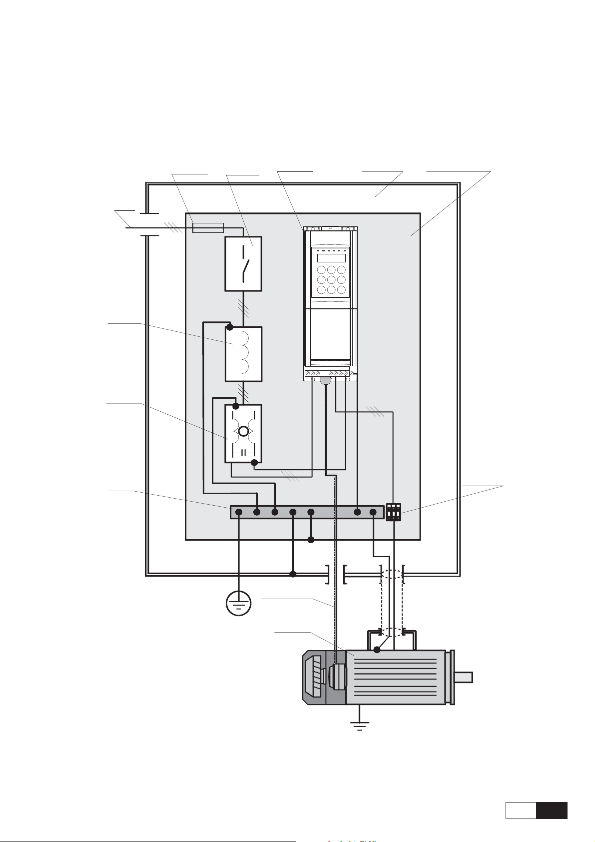
1.1. FUNCTIONAL CONNECTION DIAGRAM
AC
Power
Supply
AC
Mains
choke
EMI filter
AC fuses
AC Mains
Contactor
AC Drive
U1 V1W1
U2 V2W2PE2PE1
Cabinet
Mounting panel
Ground
Bus
Motor
cable
terminals
Encoder cable
AC Motor
NOTE: PE1 is the drive safety ground. If PE2 is used to connect the motor ground, EMI filter
ground must be connected to PE1.
—————— Quick Start up ——————
13
QS
Page 14

1.2. OVERVIEW
This guide assumes a standard start up using the
keypad for a drive and motor that is to be run in either
sensorless vector or flux vector (with digital or
sinusoidal encoder for feedback) mode. It is also
assumed that a standard scheme is to be used for
control. In other words, that the drive will be run
from pushbuttons (or contacts) and the speed will be
set from a pot input (or 0 to 10 vdc source). While
the drive has more modes of operation and dozens
of combinations of more exotic and complex optional
configurations, this guide will cover most
applications that are not being started up by a service
engineer anyway. The manual can always be used to
do more complex changes to standard configuration
beyond this set up.
Standard Wiring: see the manual for the standard
suggested configuration for wiring. Note that if this
is a system designed and wired by our factory, the
set up of the drive (aside from tuning the motor) has
already been done and this Quick Start up guide is
not applicable. You will instead, need to use the
Quick T uning guide for Factory Configured Drives
(AVy) located in this guide.
NOTE:
Memory: There are two memories for set-up
parameters. One is the active memory which is
always the one currently in use by the drive. The
other is the permanent memory which is the one the
drive will use if power is lost and then restored. Note
that power up is the ONLY time when the drive looks
at permanent memory. All file uploads and
downloads, all changes, etc. are made only to the
active memory and read from the active memory. The
only time permanent memory is used in any way is
that when it is booted into active memory on power
up, and when it is changed to new values by the “Save
Parameters” command. When parameters are
changed during set
parameters but unless you “SAVE PARAMETERS”
these changes will not be permanent and upon
recycling power, you will lose the changes. This is
an advantage if you are “trying” something to see
how it works and don’t intend to change your
permanent set-up.
up, the drive will use those
Quotes: Quote marks are put around words which
will be seen in the display window of the keypad.
Menu Navigation: in the directions below, you will
be directed to press keys to get to some menu item.
In many cases, the key will have to be pressed more
than once to get to the displayed value. Note that the
display has two lines, the top line always shows the
next HIGHER level of the menu than where you are.
All of the menu items referred to in this start up means
look for that item in the SECOND LINE of the
display. What is displayed on the top line is for
information only and has nothing to do with entering
data. If the directions say to press the
to “Regulation Mode” it means keep pushing the
[Down arrow] until “Regulation Mode” is displayed
in the Second line. If you get confused, look in the
manual and it shows the complete menu structure.
I/O Connections: the drive WILL NOT OPERATE
unless the hardware enable (I/O terminal 12) and
the other interlocks are made. It is suggested to make
things simple, to temporarily connect the digital
inputs as follows:
Jumper 16 to 18, jumper 19 to 15, jumper 15 to 14,
jumper 12 to 13, and connect a simple switch between
13 and 14. This is low voltage logic, so if you don’t
have a switch, just leave two short pieces of bare
wire to twist (or untwist) together. Turning the switch
on and off will now enable and disable the drive (and
start and stop at the same time) and all other necessary
interlocks will be made correctly to test the drive. If
you have control over the I/O already with the
connected logic and can make the same connections
with your own pushbuttons/contacts, the drive can
be enabled with those, but this eliminates any
possibility of external wiring problems making set
up a problem.
[Down arrow]
Underline: Below, when words are underlined, they
refer to a key on the keypad labeled that way.
QS
14
AVy -HGB
Page 15
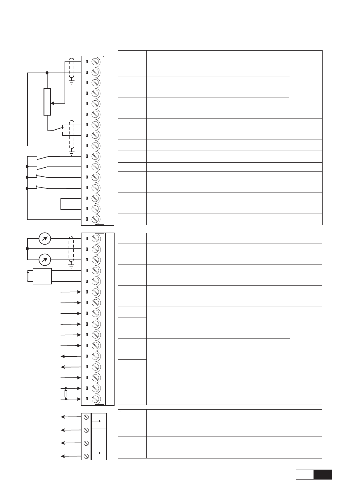
1.3. CONTROL TERMINALS
1
2
3
4
5
6
7
8
9
12
13
14
15
16
18
19
Strip X1
Analog input 1
Analog input 2
Analog input 3
+10V
-10V
0V
Enable drive
Start
Fast stop
External fault
COM D I/O
0V24
+24V OUT
Function
Programmable/configurable analog differential input. Signal: terminal 1.
Reference point: terminal 2. Default setting: Ramp ref 1
Programmable/configurable analog differential input. Signal: terminal 3. 0.25mA
Reference point: terminal 4. Default setting: none (20mA when
Programmable/configurable analog differential input. Signal: terminal 5.
Reference point: terminal 6. Default setting: none. (1)
Reference voltage +10V; Reference point: terminal 9 +10V/10mA
Reference voltage -10V; Reference point: terminal 9 -10V/10mA
Internal 0V and reference point for±10V -
Inverter enable; 0V or open: inverter disabled; +15…+30V: Inverte enabled
Inverter start command; 0V or open: No start; +15…+30V: Start 3.2mA @ 15V
OV or open: Fast stop. +15…+30V: No Fast stop.
OV or open: External fault. +15…+30V: No External fault
Reference point for digital inputs and outputs, term.12...15, 36...39, 41...42
Reference point for + 24V OUT supply, terminal 19 -
+24V supply output. Reference point: terminal 18 or 27 or 28
max
±10V
current ref
input)
+30V
5mA @ 24V
6.4mA @ 30V
-
+22…28V
120mA @ 24V
BU-
External braking
unit (optional)
R1K
Analog output
21
22
23
26
27
28
29
36
37
38
39
41
42
46
78
1
0V
Analog output
2
BU comm.
output
0V24
RESERVED -
RESERVED
Digital input 1 +30V
Digital input 2 3.2mA @ 15V
Digital input 3 5mA @ 24V
Digital input 4 6.4mA @ 30V
Digital output
1
Digital output
2
Supply D O
Motor PTC
Program.analog output; def.setting: Motor speed. Ref. point: term.22
Internal 0V and reference point for terminals 21 and 23
Program.analog output; def.setting: Motor current. Ref. point: term.22
VeCon controlled BU-... braking units command. Ref. point: term.27.
Reference point for BU-... command, terminal 26
Programmable digital input; default setting: none
Progr. digital input; def. setting: none. Configurable as 2nd encoder index qualifier
(setting via S30 jumper, )”Digital input 3” parameter must be set 0=OFF
Programmable digital input; default setting: none. Configurable as 1st encoder
index qualifier (”Digital input 4” parameter must be set 0=OFF ).
Programmable digital output; default setting: none
Supply input for digital outputs on terminals 41/42. Ref. point: term.16.
Motor PTC sensing for overtemperature (cutoff R1k if used)
79
±10V/5mA
-
±10V/5mA
+28V/15mA
-
+30V/40mA
+30V/80mA
1.5mA
80
82
83
85
Strip X2
OK relay
contact
Relay 2
contact
Function max curr.
Potential- relay contact OK relay (closed=OK)
Potential-relay contact configurable (relay 2).
Default: open 0 drive stopped
—————— Quick Start up ——————
250V AC
1AAC11
250V AC
1AAC11
15
QS
Page 16
1.3.1 Maximum cable cross section for regulator terminals
Maximum Permissible Cable Cross-Section Tightening
Terminals
[mm
2
]
AWG
torque
flexible multi-core [Nm]
1 ... 79 0.14 ... 1.50.14 ... 1.528... 16 0.4
80 ... 85 0.14 ... 1.50.14 ... 1.528... 16 0.4
Ai4090
NOTE: Terminal board points are intended for 1 wire/point. Daisy chains and multiple wires/point are
better done with a panel monted terminal board.
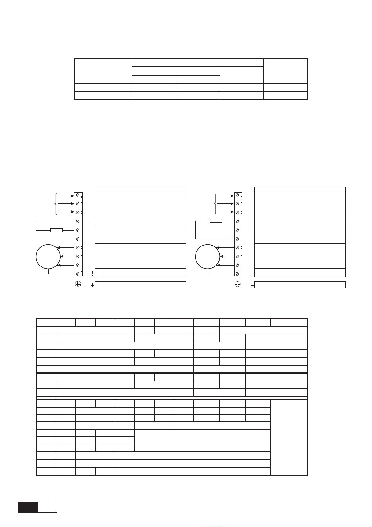
1.4. POWER TERMINALS
Figure 1.4.1: Power Terminals connection
3Ph~
Braking resistor
(optional)
M
U1/L1
V1/L2
W1/L3
BR1
C
D
U2/T1
V2/T2
W2/T3
PE2/
Function (max) - Sizes 1007 … 3150
(3x480 V +10% 3Ph,
Braking unit resistor circuit (braking resistor
AC mains voltage
AC
must be connected between BR1 and C)
DC link circuit connection
(770 V / 1.65 output current)
DC
(AC line volt 3Ph, 1.36 output current)
Motor connection
Motor ground connection
see table 3.3.2.1)
3Ph~
Braking resistor
M
(optional)
U1/L1
V1/L2
W1/L3
C
D
BR1
U2/T1
V2/T2
W2/T3
PE2/
Function (max)- Sizes 4220… 81600
(max 3x480 V +10%, see table 3.3.2.1)
Braking unit resistor circuit (braking resistor
must be connected between BR1 and C)
AC mains voltage
AC
DC link circuit connection
(770 V / 1.65 output current)
DC
Motor connection
(AC line volt 3Ph, 1.36 output current)
Motor ground connection
PE1 /
Grounding (protective earth) conductor
1.4.1 Maximum cable cross section for power terminals
1007 1015 1022 1030 2040 2055 2075 3110 3150 4185 4220
AWG
[mm2]
[Nm]
AWG
[mm2]
[Nm]
AWG
[mm2]
[Nm]
AWG
[mm2]
[Nm]
AWG
[mm2]
[Nm]
AWG
[mm2]
[Nm]
14
12 8
2
0.5 to 0.6
14 10
12 8 6
24
0.5 to 0.6 1.2 to 1.5
14
12 8 6
2
4300 4370 5450 5550 6750 7900 71100 71320 81600 82000
4 1/0 2/0 4/0 300* 350* 4xAWG2 * = kcmils
25 50 70 95 150 185 4x35 150** **: copper bar
3
88
10 10
1.6 1.6
6
16
2
35
4 12 10-30
6
16
3
6
16
33
10
4
10
4
terminals not available
50
4
810
1.2 to 1.5
810
810
1.2 to 1.50.5 to 0.6
2
PE1 /
Grounding (protective earth) conductor
6
16
2
10
6
0.9
6
16
2
avy4040
QS
16
AVy -HGB
Page 17
1.5 ENCODER TERMINALS (XE CONNECTOR)
Designation
PIN 1
PIN 2 +8V Encoder supply voltage O +8 V 200 mA
PIN 3
PIN 4
PIN 5
PIN 6
PIN 7GND
PIN 8
PIN 9 AUX+
PIN 10
PIN 11
PIN 12
PIN 13
PIN 15 I
ENCB-
ENCC+
ENCC-
ENCA+
ENCA-
ENCB+
HALL 1+/SIN+
HALL 2+/COS+
HALL 2-/COS-
HALL 3+
HALL 3-
Channel B- 5 V digital or 10 mA digital or
Incremental encoder signal B negative 1 V pp analog 8.3 mA analog
Channel C+ 5 V digital or 10 mA digital or
Incremental encoder signal Index positive 1 V pp analog 8.3 mA analog
Channel C- 5 V digital or 10 mA digital or
Incremental encoder signal Index negative 1 V pp analog 8.3 mA analog
Channel A+ 5 V digital or 10 mA digital or
Incremental encoder signal A positive 1 V pp analog 8.3 mA analog
Channel A- 5 V digital or 10 mA digital or
Incremental encoder signal A negative 1 V pp analog 8.3 mA analog
Reference point for +5V encoder supply voltage
Channel B+ 5 V digital or 10 mA digital or
Incremental encoder signal B positive 1 V pp analog 8.3 mA analog
+5V encoder supply voltage
Channel HALL1 + / SIN+ 5 V digital or 10 mA digital or
Reserved 1 V pp analog 8.3 mA analog
Channel HALL 1- / SIN- 5 V digital or 10 mA digital or
Reserved 1 V pp analog 8.3 mA analog
Channel HALL 2+ / COS+ 5 V digital or 10 mA digital or
Reserved 1 V pp analog 8.3 mA analog
Channel HALL 2- / COS- 5 V digital or 10 mA digital or
Reserved 1 V pp analog 8.3 mA analog
Channel HALL 3 + 5 V digital or
Reserved 1 V pp analog
Channel HALL 3 - 5 V digital or
Reserved 1 V pp analog
Function I/O Max. voltage Max. current
I
I
I
I
I
O
I
O
I
IHALL 1-/SIN-
I
I
I
––
+5 V 200 mA
10 mA digitalPIN 14
10 mA digital
ai3140
1.5.1 Encoder type connection
Encoder type
DE 8 pole
SE 8 pole
DE 8 pole
SE 8 pole
- DE: 5V digital incremental encoder with
- SE: 5V sinusoidal incremental encoder with
Shielded
cable
123456789101112131415
B- +8V C+ C- A+ A- 0V B+ +5V E+ E- F+ F- G+ G-
Internal +5V Encoder Power Supply
l lllllll
l lllllll
Internal +8V Encoder Power Supply
lllllll l
lllllll l
A/A,B/B,C/C
XE CONNECTOR PIN
ai3160
A/A,B/B,C/C
—————— Quick Start up ——————
17
QS
Page 18
1.5.2 Jumpers setting
Encoder / Jumpers setting S11 S12 S13 S14 S15 S16 S17 S18 S19 S20 S21 S22 S23
DE OFF OFF OFF OFF OFF OFF ON (*)
SE ON ON ON ON ON ON
- DE: 5V digital incremental encoder with
A/A,B/B,C/C
- SE: 5V sinusoidal incremental encoder with
- ------
A/A,B/B,C/C
------
(*) If the encoder is not provided with the zero channel S17=OFF
1.5.3 Maximum cable length for encoder terminals
ai3150
Cable section [mm2]
Max Length m [feet] 27 [88] 62 [203] 93 [305] 125 [410] 150 [492]
0.22 0.50.751 1.5
avy3130
QS
18
AVy -HGB
Page 19

1.6. LIST OF JUMPERS AND DIP-SWITCH
Designation Function Factory setting
S5 - S6 Terminating resistor for the serial interface RS485 ON (*)
ON= Termination resistor IN
OFF= No termination resistor
S8
S9
S10
S11 - S12 - S13 Encoder setting ( jumpers on kit EAM_1618 supplied with the drive) OFF
S14 - S15 - S16 ON=Sinusoidal SE
S17 Monitoring of the C-channel of the digital encoder OFF
S18 - S19 Encoder setting B
S20 - S21 Pos. B= reserved
S22 - S23 Analog input 3 enabling (alternative with SESC encoder) B
S26 - S27 Reserved ON
S28
S29 Internal use A
S30
S34
S35
S36 Internal use not mounted
S37 Internal use not mounted
S38-S39 Internal use ON
S40-S41
(**)
Adaptation to the input signal of analog input 1 (terminals 1 and 2)
ON=0...20 mA / 4...20 mA
OFF=0...10V/-10...+10 V
Adaptation to the input signal of analog input 2 (terminals 3 and 4)
ON=0...20 mA / 4...20 mA
OFF=0...10V/-10...+10 V
Adaptation to the input signal of analog input 3 (terminals 5 and 6)
ON=0...20 mA / 4...20 mA
OFF=0...10V/-10...+10 V
OFF=Digital DE
ON=C-Channel monitored
OFF=C-Channel not monitored (required for single-ended channels)
Pos. A= reserved
Pos. A= reserved
Pos. B=analog input 3 enabled
Pos. OFF= resolver
Encoder Internal power supply selection
ON/ON=+5V
OFF/OFF=+8V
Second encoder qualifier input
A=from EXP-… board
B=from digital input "3" on RV33-4
Jumper to disconnect 0V (+24V power supply) from ground ON
ON = 0V connected to ground (hard-wire)
OFF = 0V disconnected from ground
Jumper to disconnect 0V (regulation board) from ground ON
ON = 0V connected to ground (hard-wire)
OFF = 0V disconnected from ground
Power supply for the serial interface RS485 OFF
ON = Internal power supply (from pins XS.5 / XS.9)
OFF = External power supply (to pins XS.5 / XS.9)
(*)
on multidrop connection the jumper must be ON only for the last drop of a serial line
(**)
see chapter 5.4
OFF
OFF
OFF
ON/ON
A
Ay4060
—————— Quick Start up ——————
19
QS
Page 20
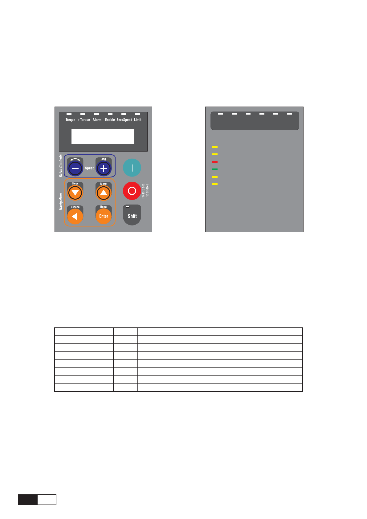
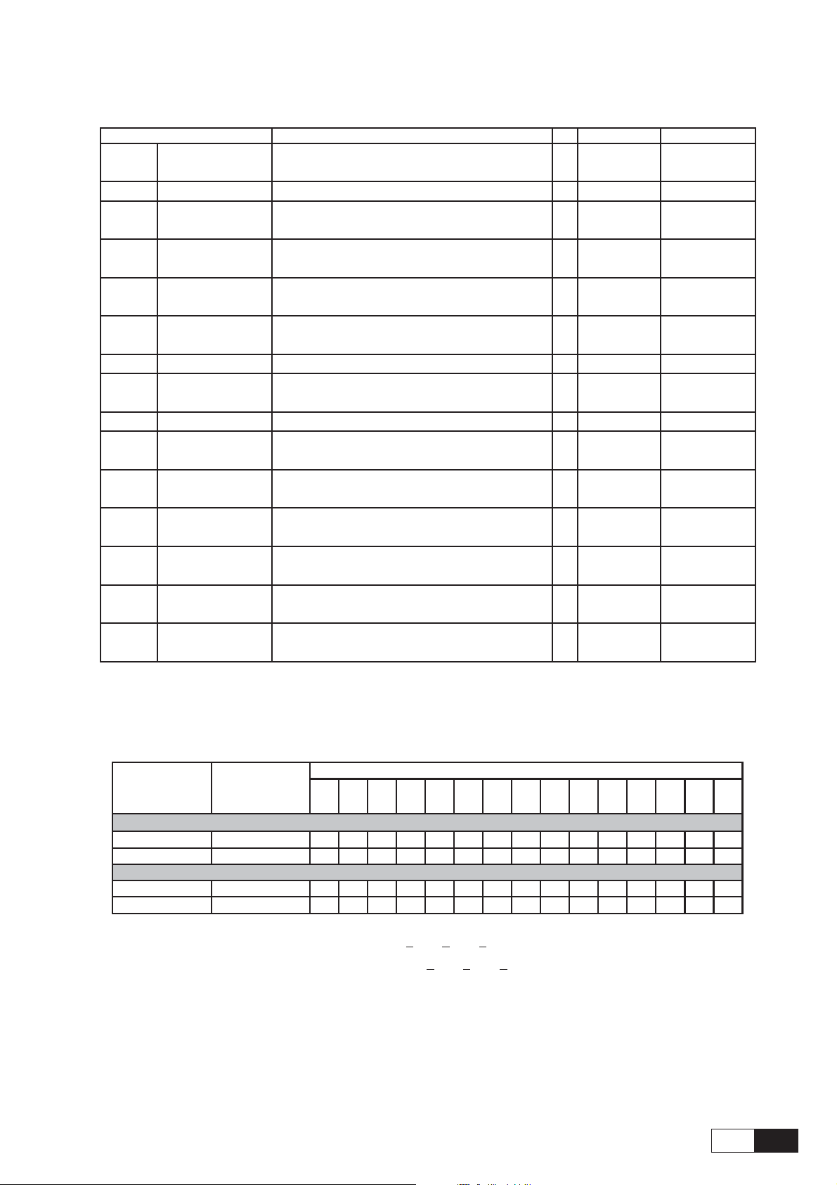
1.7. KEYBOARD OPERATION
The keypad is made of a LCD display with two 16-digit lines, seven LEDs and nine function keys. It is used:
- to control the drive, when this kind of use has been programmed (Main commands=DIGITAL)
- to display the speed, voltage, diagnostics etc. during the operation
- to set the parameters
-Torque +Torque Alarm Enable ZeroSpeed Limit
-Torque Negative torque current
torque current
+Torque Positive
Alarm Alarm condition
Enable Drive enable status
ZeroSpeed Speed <=zero speed threshold
Limit Actual current >=current limit
This monitoring module can be upgraded with the keypad with
alphanumeric LCD display
NOTE: keypad cable longer than 20 cm must be shielded.
1.7.1 LEDs & buttons
The LEDs present on the keypad are used to quickly diagnose the operating state of the drive.
Designation Color Function
-Torque yellow the LED is lit, when the drive operates with a negative torque
+Torque yellow the LED is lit, when the drive operates with a positive torque
ALARM red the LED is lit; it signals a trip
ENABLE green the LED is lit, when the drive is enabled
Zero speed yellow the LED is lit; it signals zero speed
Limit yellow the LED is lit, when the drive operates at a current limit
Shift yellow the LED is lit, when the second keypad functions are enabled
ai5010
QS
20
AVy -HGB
Page 21

Control
buttons
Text reference
[START]
[STOP]
Function
START button commands the Drive to the Enable (Stop control
function ON) and Run state (Main commands = DIGITAL)
When Main commands is set as TERMINALS the button is
not active
STOP button commands to stop the Drive from the Run state
when Main commands is set as DIGITAL
(Pressing this button for 2 sec, the drive will be disabled).
When Main commands is set as TERMINALS the button is
not active.
Jog
Help
Alarm
[Increase] / [Jog]
[Decrease] / [Rotation control]
[Down arrow] / [Help]
[Up arrow] / [Alarm]
Plus button increases the speed reference for Motor pot function.
JOG command, when shift button is selected.
Minus button decreases the speed reference for Motor pot
function.
Rotation control, it changes the motor rotation direction in Jog
mode and Motor pot function when shift button is selected.
Down arrow - Used to change menu or parameter selection.In
parameter and reference setting modes, it changes the value of
the parameter or the reference.
Help – Function Not available (“Help not found” displaying
when pressed and when shift button is selected)
Up arrow - Used to change menu or parameter selection.
In parameter and reference setting modes, it changes the value
of the parameter or the reference.
Alarm - Failure register displaying ( shift selected). Use the UP/
DOWN Arrows to scroll through the last 10 alarms.
Escape
Home
Enter
Shift
[Left arrow] / [Escape]
[Enter] / [Home]
[Shift]
—————— Quick Start up ——————
Left arrow, when editing numeric parameters it selects the digit
of the parameter to modify. In the other cases it is used to exit
from setting mode.
Escape - Used to exit from setting mode and (Reset) Alarm
displaying mode (when shift button is selected)
[Enter] - Used to [Enter] a new value for a parameter in the
parameter setting mode.
Home - Used to go directly to BASIC MENU (when shift button
is selected)
Shift button enables the second keypad functions (Rotation
control, Jog, Help, Alarm, Escape, Home)
21
QS
Page 22
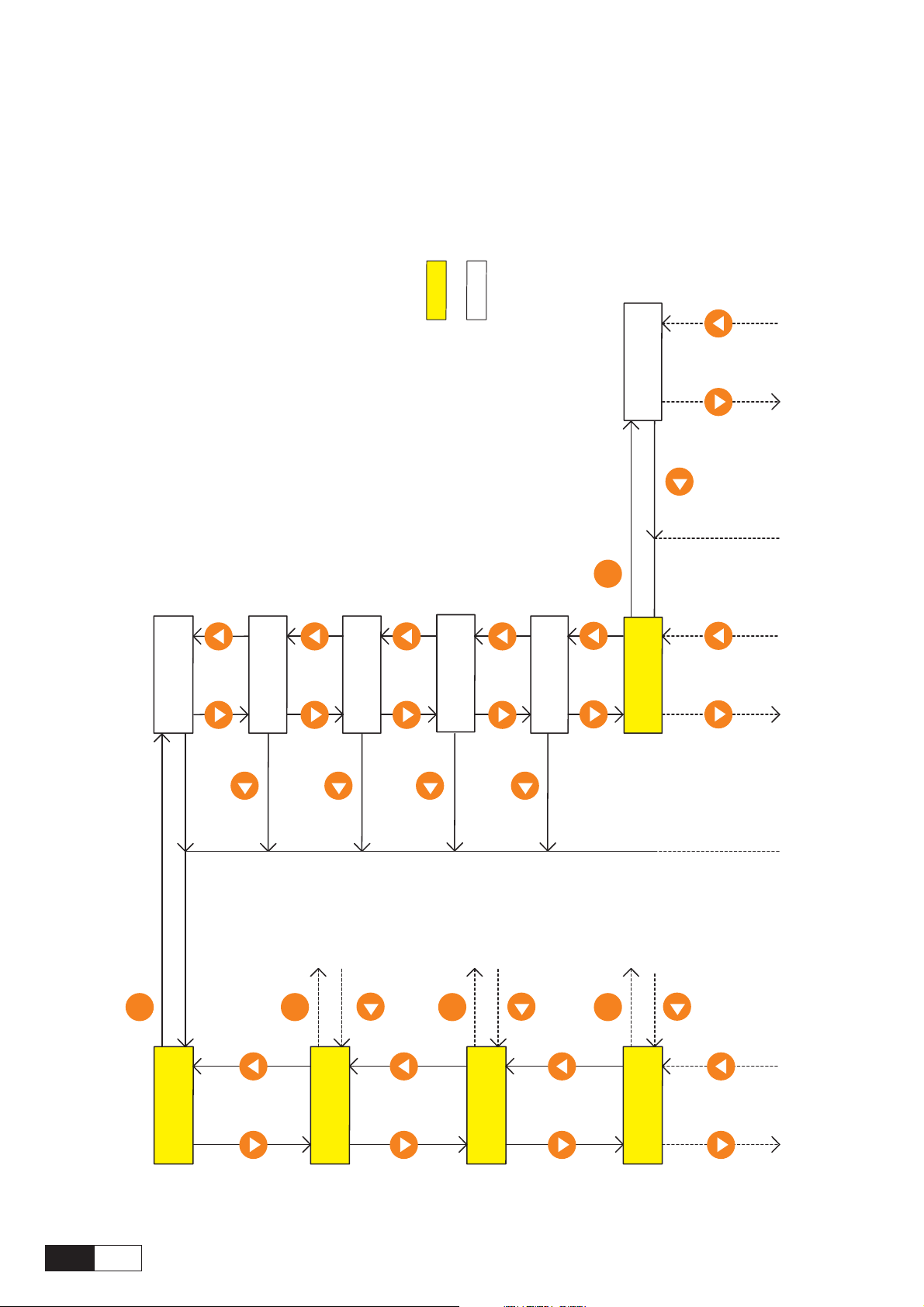
1.7.2 Moving inside a menu
3rd level
Menu
Parameter
Drive type
Mains voltage
2nd level
Enter
BASIC MENU
Enable drive -/+
BASIC MENU
Ramp ref 1
Enter
BASIC MENU
Start/stop
BASIC MENU
Actual spd
Enter
BASIC MENU
Motor current
Enter
Enter
BASIC MENU
Drive type
QS
22
Main menu
AVy
BASIC MENU
AVy
R
MONITO
AVy -HGB
AVy
DRIVE PARAMETER
AVy
INPUT VARIABLES
Page 23

1.8. PRE POWER CHECKS
The following should be checked before switching ON the Drive:
Grounds / Grounding
· Verify ground connections Drive to motor
· Verify AC Input, AC Output and control wiring aren’t grounded
Connections
· Verify AC Input (U1/L1, V1/L2, W1/L3), AC Output (U2/T1, V2/T2, W2/T3), DC link connection with
an optional external braking unit (C,D), Motor thermistor (78,79), OK Relay (80,82 n.o), Relay2 (83,85
n.o.) and regulation board (1.....46, XS, XE) connections
12 ENABLE DRIVE (close to activate)
13 START (close to activate)
14 FAST STOP (open to activate)
15 EXTERNAL FAULT (open to activate)
16 Common for terminal board
18 + 24V Common
19 +24VDC (internal)
Setting jumpers and switches on Regulation board
· Enable drive (terminal 12) and Start (terminal 13) OPEN
· Fast stop (terminal 14) and External fault (terminal 15) CLOSED
. Record motor name plate data, encoder information and mechanical data.
MOTOR DATA
HP (kW)
Amps
Volts
Hz
rpm
Cos phi (power factor)
Tach type
Tach PPR
Motor rotation for machine fwd direction [CW/CCW]
Gearbox ratio
Dai54123
—————— Quick Start up ——————
23
QS
Page 24

1.9. QUICK TUNING
1. After a complete check of wiring and input
voltage levels and then turn the power on:
·V erify the following voltages must be present:
Terminal 7, +10V to terminal 9 (on regulation
board)
Terminal 8, -10V to terminal 9 (on regulation
board)
Terminal 19, +24…30V to terminal 18 (on
regulation board)
·Check DC link voltage by pressing
arrow] to get “MONITOR”, then [Enter], then
[Down arrow] to“measurements”, then [Enter],
then
[Down arrow] to “DC link voltage”, then
[Enter].
The value should be:
480-650 vdc for 400 vac input
550-715 vdc for 460 vac input
If it is not within these values, check your line
voltage, as it is unlikely the drive will work
properly.
2. Default to Factory V alues: If you are not already
certain of the drive configuration, it is necessary to
default to factory values or copy in a file from a PC
to be certain you are starting from a known
configuration. To default to factory values:
· Default to working memory: Push
arrow] to get back to “MONITOR”, then [Down
arrow] to “SPEC FUNCTIONS” and then [Enter].
Push
[Down arrow] to “Load Default” and
[Enter]. The factory values will now be loaded
into working memory for all parameters but the
previous values are still in permanent memory.
3. Set Line Voltage:
· Press
4. Adaption to maximum ambient temperature:
[Left arrow] to “SPEC FUNCTIONS”
then
[Up arrow] to “BASIC MENU”, then
[Enter], then [Down arrow] to “Drive type”,
then
[Enter] to “Mains voltage” and [Enter].
Now using the
change the voltage value closest to your nominal
AC input rating. Then
· Press
[Enter]. Now using the [Up arrow] / [Down
arrow] keys, set the maximum ambient
temperature value: 40°C or 50°C, then
[Up arrow] / [Down arrow] keys,
[Enter] to set the value.
[Down arrow] to “Ambient temp” then
[Down
[Left
[Enter].
5. Load Default Motor Values:
· Press
MENU” and then
PARAMETER”, then
arrow] to “Motor Parameter”, [Enter], then
[Down arrow] to “Load Motor Par” and [Enter].
Use the
display is the correct motor voltage, then
For 460 VAC motors, select 460, and for 380/400
VAC motors select 400.
6. Set Actual Motor Data:
· Press
PARAMETER”, then
data” and
[Enter] again to see the value. Using the [Up
arrow]/[Down arrow] keys to change the value
and the
position. When correct press
· Press
[Enter], then use the [Up arrow] / [Down
arrow] keys to get the nominal speed on the
motor nameplate. Press
some manufacturers of vector motors put the
synchronous speed (exactly 600, 900, 1500,
1800, 3600) for the nominal speed, rather than
the slip speed it would run if run on 50 Hz power.
If this is done, you MUST put a slip speed in this
data. Figure 20 rpm less than the synchronous
speed for these cases.
· Press
[Enter] and set to the nominal frequency on the
nameplate (50 or 60 Hz usually) by using the
[Up arrow] / [Down arrow] keys. Press [Enter]
to set data.
· Press
[Enter] and set to the nominal current on the motor
nameplate (rated current) by using the
/
[Down arrow] keys. Press [Enter] to set data.
· Press
and set to the nominal power factor on the
nameplate by using the
arrow] keys (accept the default if you don’t
know). Press
· Press
[Enter] and set to the base voltage by using the
[Up arrow] / [Down arrow] keys (usually rated
voltage). Press
manual for both Base Voltage and Base
Frequency when operating the motor above
normal synchronous speed.
· Press
[Enter], set to the base frequency by using the
[Up arrow] / [Down arrow] keys (usually rated
frequency). Press
[Left arrow] until back to “BASIC
[Down arrow] to “DRIVE
[Enter], then [Down
[Up arrow]/[Down arrow] keys until the
[Left arrow] until back to “DRIVE
[Enter] to get “Mot plate
[Enter] to “Nominal Voltage” then
[Left arrow] to move the character
[Enter].
[Down arrow] to “Nominal speed”,
[Enter] to set data. Note,
[Down arrow] to “Nom frequency” and
[Down arrow] to “Nominal current” and
[Up arrow]
[Down arrow] to “Cos phi” and [Enter]
[Up arrow] / [Down
[Enter] to set data.
[Down arrow] to “Base Voltage” and
[Enter] to set data. Look in the
[Down arrow] to “Base Frequency” and
[Enter] to set data.
[Enter].
QS
24
AVy -HGB
Page 25

· Press [Down arrow] to “Take motor par” and
[Enter] and set all the motor parameters. If, when
you do this, a message saying “Over-range
error XXX” appears, there is something wr ong
with the data you have entered. The drive has
NOT ACCEPTED the values you have entered.
The most common cause of this is trying to
[Enter] a value for “Nominal Current that is less
than 30% of the drive rating. This is not allowed
due to problems in control of a large drive on a
very small motor. Try to go back to the beginning
of step 6 and repeat the entries. If this doesn’t
work, see Overflow list in chapter 1.12,
“Troubleshooting” or contact your service office.
10. Prepare for Self Tune:
The keypad will be used for this purpose but the
I/O needs to be connected properly so the
hardware enable/disable functions.
11. Save Parameters:
· Press
arrow] until “Basic Menu” then [Enter], then
[Down arrow] to “save parameters”, then
[Enter].
The display will read “wait” until the values are
permanently stored.
[Left arrow] until to “limits”, then [Up
7. Set Drive Base Values:
· Press [Left arrow] until back to “drive
parameter” then
“configuration”, then
· Press
then
speed on the motor nameplate, press
· Press
[Enter] and set the DRIVE (not motor) rated full
load current on the drive nameplate by using the
[Up arrow] / [Down arrow] keys, then press
[Enter] to set.
8. Set Regulation Mode: (V7f, Sensorless vect or
Field oriented mode )
· Press
[Enter] and use [Up arrow] / [Down arrow]
keys to select “sensorless vect” or “Field
oriented” then
· If “Field oriented” mode is select:
· Press
then press
1 type”, then
[Down arrow] keys to select sinusoidal encoder
or digital encoder, then
· Press
[Enter] and set the value using the [Up arrow]/
[Down arrow] keys to the ppr (pulses per
revolution) of your encoder (usually 1024),
9. Speed Limit:
· Press
[Down arrow] to “Limits”, then [Enter] for
“Speed Limits”, then
Amount”, then
Press
and
to the maximum speed of the motor using the
[Up arrow]/[Down arrow] keys as before (for
now set it to 105% of the rated motor speed).
Press
[Down arrow] to “Speed Base Value”
[Enter] and set the nameplate rated full load
[Down arrow] to “full load current” then
[Up arrow] to “Regulation mode”, then
[Enter].
[Down arrow] until to “Motor spd fbk”,
[Enter], [Down arrow] to “Encoder
[Enter]. Use the [Up arrow]/
[Down arrow] to “Encoder 1 pulses”, then
[Left arrow] until “Basic Menu”, then
[Enter] to “Speed Min Amount”.
[Down arrow] to “Speed Max Amount”,
[Enter]. Change the value from 5000 rpm
[Enter].
[Down arrow] to
[Enter].
[Enter].
[Enter].
[Enter].
[Enter] for “Speed
12. Self Tune:
Make sure power is on and drive not enabled.
Close the switch on terminal 12 (hardware enable
has 24 Vdc on it).
· When the enable switch is made, Press
arrow] until “Basic Menu” then [Down arrow]
to “Drive Parameter”, then
arrow] to “motor parameters” and [Enter].
Press “
[Enter] to see “self tune 1”. Press [Enter] to see
“start part 1” and
[Enter] again. The keypad should show the
“enable” led illuminated, if not, make sure that
you have the jumpers (or external switches) set
so that 24 Vdc exists on 12, 13, 14, 15, with
respect to 16 or 18.
· You should now see “measuring Rs” (stator
resistance). Wait until the display says “end”,
then disable the drive (open the switch to 12)
and push
1”, press
way to “take val part 1” and
will read “wait” until the values are stored.
NOTE:
13. Self Tune part 2:
The initial part of self tuning that can be done
without the motor rotating has been
accomplished, now in order to get the best
possible tuning, the motor needs to be free to
turn with no load attached to the shaft. For this
we use Self tune mode 2a. If, for any reason, the
motor cannot be made free to rotate with no load,
then a “close” level of tuning can still be
accomplished by selecting Self tune mode 2b.
· Now press
then
press
[Down arrow] to “Self Tuning” and
[Enter], “start part 1 ?” and
[Left arrow] twice to see “self tune
[Enter], then [Down arrow] all the
“xxx range error” or “timeout” messages
may also occur in some extreme parameter
ranges. Repeat execution in this case. If
error messages are persistent see
troubleshooting section.
[Left arrow] to see “self tune 1”
[Down arrow] to “self tune 2a or 2b and
[Enter]. Enable the drive using the switch
[Enter], then [Down
[Enter]. The display
[Left
—————— Quick Start up ——————
25
QS
Page 26

to terminal 12. Press [Enter], “start part 2a ?”
or “start part 2b ?” then
sat 2a (or b)” will appear and the motor shaft
will turn (if “self tune 2a” is select). Wait until
the display says “end”, press
see “self tune 2a (or b)” then
[Down arrow] to see “take val part 2a (or b)”.
Disable the drive (switch off terminal 12), then
[Enter].
NOTE:
14. Self tune part 3:
“xxx range error” or “timeout” messages
may also occur in some extreme parameter
ranges. Repeat execution in this case. If
error messages are persistent see
troubleshooting section.
If there was some reason you did not want
to keep these values permanently, but only
wanted to try to run the drive with them,
there is no need to save to permanent
memory. If power is cycled however, these
values just obtained will be lost unless the
next step is taken.
The third part of self tuning (Speed regulator
tuning) identifies the total inertia value at the motor
shaft, the friction value and computes the
proportional and integral gains of the speed
regulator. The motor needs to be free to turn with
load attached to the shaft.
[Enter] and see “measure
[Left arrow] to
[Enter] and press
WARNING !
This procedure requires free rotation of the
motor shaft coupled to the load. Start/Stop
command is disregarded, therefore it can not
be used on drives with limited travel.
CAUTION !
The test is performed using the torque limit
value set in Test T curr lim parameter. The
torque is applied stepwise, with no ramp
(profile), therefore the mechanical transmission must not have significant backlash, and
it must be compatible with operation at the
torque limit set in Test T curr lim parameter.
The user can reduce the torque limit to a
suitable value via the Test T curr lim
parameter.
NOTE !
- Application where the system inertia coupled to the motor shaft is much higher than
the motor inertia value , increase the Test T
curr lim parameter to avoid “Time out” error.
- This procedure is not suitable for use
with “hoist” or “elevator” drives.
- Encoder feedback is required when Field
oriented mode is selected.
- Set the current limit (BASIC MENU\ T
Current lim +/-) to a value compatible with
the motor size and load. (Example when
motor is 1/3 of the Drive power, the limit
should be reduced compared to the default
value).
- Select the torque current value to be used
during the test via the Test T curr lim
parameter
· Now press
or 2b” then
press
[Enter] to Fwd-Rev spd tune, then [Enter],
set the motor shaft direction for this test: Forward
or Reverse by using
keys. Press
· Enable the drive using the switch to terminal
12 [and close terminal 13 to terminal 19 if Speed
control function is enabled (default)]. Press
[Down arrow] to “Start part 3” then press
[Enter], “start part 3 ?” then [Enter] and see
“measure speed” will appear and the motor will
turn. Wait until the display says “end”, press
arrow] to see “self tune 3” then [Enter] and press
[Down arrow] to see “take val part 3”. Disable
the drive, then
the initial set up and tuning with values stored in
only in the “working memory”.
NOTE:
NOTE:
15. Set up for Running:
“xxx range error” or “timeout” messages
may also occur in some extreme parameter
ranges. Repeat execution in this case. If
error messages are persistent see chapter
1.12, “Troubleshooting”
If there was some reason you did not want
to keep these values permanently, but only
wanted to try to run the drive with them,
there is no need to save to permanent
memory. If power is cycled however, these
values just obtained will be lost. To save
all values to permanent memory, select
Save parameters and press
First, before saving, let’s put the drive into the
configuration you want to run it in.
The drive is factory setting to run through an
external +/- 10V reference using a potentiometer
connected to terminals 1, 2 (see table 5.3.2.1). If
you would like to run the motor using the keypad
through the Increase
(Enable motor pot parameter = Enabled), see
the following instruction to run.
If a change of the default acceleration / decel-
eration ramp time value is needed, using the Acc
delta time / Acc delta speed and Dec delta time
/ Dec delta speed is possible to set the desidered
value.
[Left arrow] to see “self tune 2a
[Down arrow] to “self tune 3” and
[Up arrow] / [Down arrow]
[Enter] to set the selection.
[Enter]. You are now finished with
[Enter] .
[+] and Decrease [-] keys
[Left
QS
26
AVy -HGB
Page 27
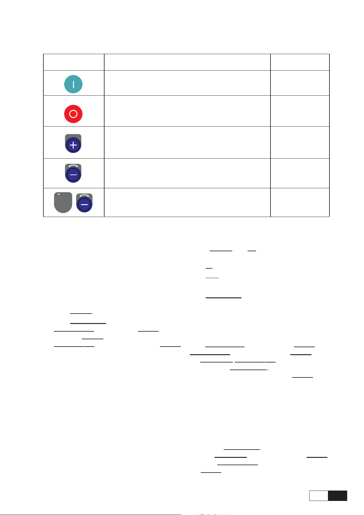
1.9.1 Motor Potentiometer
Control buttons
Sequencing
Press START button to command the Drive to the Enable
and Run state
Press STOP button commands to stop the Drive from the
Run state
Jog
Press to display the current reference value and to increase
the reference value and accelerate the drive.
Press to decrease the reference value and decelerate the
drive.
Shift
Press SHIFT and [-] to change the motor shaft rotation
NOTE! (Main commands = DIGITAL)
Enable drive, terminal 12 to
24Vdc
Start, terminal 13 to 24Vdc
Resetting the speed reference value using Mot pot
function
Motor pot oper
Motor pot oper
Enable drive, terminal 12 to 24Vdc
Start, terminal 13 to 24Vdc
Press
[SHIFT and [+] to run, the speed will be
displayed
Press
[-] to select the motor shaft rotation
Press
[jog] to run the other direction
Press
[Left arrow] to exit from jog operation
Display
+0 [rpm] POS
-0 [rpm] NEG
· Press
· Press
[STOP] button to stop the motor
[Left arrow] until to “Basic menu”, then
[Down arrow] to “Functions”. [Enter] to motor
pot, then
[Enter] to “enab motor pot”, press
[Down arrow] to motor pot reset, then [Enter].
The diplay will read “ready” until the reference
value is set to zero.
Set motor pot disable (Enable motor pot parameter
= Disable) if you will want to use an analog voltage
(pot or otherwise) into terminal 1 for speed reference
(already factory set).
Jog function
NOTE! This function is already standard
setting enabled. (Enable jog pa-
rameter = Enabled) with a speed
reference value = 100 rpm.
(Main commands = DIGITAL)
Changing jog reference
[Down arrow] until “Functions”, [Enter], then
Press
[Down arrow] until “Jog reference”, [Enter], using
the
[Up arrow]/[Down arrow] keys to change the
value and the
position, set the reference value, then
[Left arrow] to move the character
[Enter].
If there are other changes you might want to make
to set up (see Optional Things), do them now,
and complete the following step to put everything
into permanent memory.
Saving all values to Permanent Memory:
. Press
then
Press
[Left arrow] back to “Configuration”
[Up arrow] to “basic menu” and [Enter].
[Down arrow] to “save parameters” and
[Enter]. Parameters are now stored permanently.
—————— Quick Start up ——————
27
QS
Page 28

1.10 OPTIONAL THINGS
Encoder verification: Set the Drive in V/f mode and
run the motor, enable and start the drive and set an
analog reference. If the reference is positive on
terminal 1 with respect to 2 (common) the motor
should be turning clockwise. With the motor turning
clockwise (looking at the driving shaft pointing at
you.) (you can even do this by hand while not
enabled), monitor the encoder measurement by
clicking “Monitor/measurements/speed/speed in rpm/
Enc 1 speed”. The speed should be positive, not
negative. If it is negative, then A and A- or B and Bshould be interchanged on the encoder. Now return
to the “Set Up for Running” section.
Current Limit: The current limit will have been set
to approximately 136% by default in the previous setup
(exact number is a function of the power factor but the
difference is very small). The value actually set can
be verified by (from “Basic Menu”) pressing down/
right arrow to “Limits”, then
arrow to “current limits”, then
arrow to “T current lim” and
current limit can be changed if you like to a higher (or
lower) number. Bear in mind that the ultimate limits
are based on the capacity of the drive, not the motor.
T current is the torque producing component of total
current. Settings in excess of 200% are possible,
although the motor may not be able to handle this
current. Most motors are rated only for 150% for 1
minute. The drive will protect itself though an
intelligent temperature, voltage, I
regardless of how you set this number. The drive will
provide 150% of the value in “Configuration/Full Load
Current” for 1 minute (200 % for a short time).
[Enter], then down/right
[Enter], then down right
[Enter]. The value of T
2
T algorithm
analog output 1 is set to maximum speed then max
speed will be scaled 10 Vdc (maximum output
voltage available) at “Speed Base Value” (found
under Configuration). If you wanted 5 volts out at
max speed then set the scale to 0.5. If the output
was set to Torque current (the torque producing
current, which is the part of the total motor current
that actually produces torque), then 10 Vdc would
be rated current. If you wanted the output to be
10 Vdc at 150% of “Full Load Current” (found
under Configuration) then the scale would be 0.66.
The standard factory default is already set up to
put out speed (with scale factor of 1) on analog
output 1 (terminals 21 and 22) and load (Torque
current, with scale factor of 1) on analog output 2
(terminals 23 and 22). Note that terminal 22 is a
common for both the outputs. This common can
be grounded, and should be grounded somewhere,
preferably at the load device (meter).
How to disable analog input 1 as ramp reference:
(Analog inputs 2 and 3 are already off from default,
#1 is defaulted to Ramp ref 1). This is being done
now to allow us to use the keypad to set speed in
digital way.
· Press
Config”, then
· Press
[Enter] for Analog input 1, then [Enter] to Select
input 1, then
will be “Ramp ref 1”.
· Press
“OFF” is displayed, then
[Up arrow]/[Down arrow] to “I/O
[Enter].
[Down arrow] to “Analog inputs”, then
[Enter] to display the setting, which
[Up arrow] / [Down arrow] keys until
[Enter].
I/O Configuration: This drive can be configured in
virtually any imaginable way.
The standard drive has three standard analog inputs
and gives you two analog outputs as well as six digital
inputs and two digital outputs which are assignable
and configurable. The drive is defaulted already
to provide the analog outputs as Actual speed and
load (T orque current), but may require some scaling.
To set up the drive for two analog outputs (one for
speed and one for load) for metering or other
purposes, do the following:
Refer to the “Control terminals” section of this
guide showing a description of the connection of
the regulation section and how to make them. A
more detailed description and discussion of the I/
O are showed in the manual. The analog outputs
are defaulted to a scale of 1, which means 10 volts
out at max parameter value. In other words, if
QS
28
How to enable analog input 2 as ramp reference
· Press
Config” and press
to “Analog inputs” then
input 1” then
then
again to see the set up. It says “OFF”. Use the
[Up arrow] / [Down arrow] keys to display
“Ramp ref 1” (if this setting is not already used,
or “Ramp ref 2”) and
Analog input 2 (terminals 3 and 4) will be the
ramped (accel/decel) speed reference for the
drive.
The AVy manual on CD-ROM shows the entire configuration of the I/O and other set up for the drive. It
this does not help, call the customer service and we
can help you with your specific configuration.
AVy -HGB
[Up arrow]/[Down arrow] to “I/O
[Enter], then down right arrow
[Enter] for “Analog
[Down arrow] to ”analog input 2
[Enter] to “select input 2”, then [Enter]
[Enter]. This means the
Page 29

1.11 QUICK TUNING GUIDE FOR
FACTORY CONFIGURED (OR PRECONFIGURED) DRIVES
When the drive configuration has already been set
and you are simply tuning a motor which has not
been tuned, you can ignore most of the preceding
procedure, since it has already been done, but unless
you are certain, it is recommended that you go
through the steps anyway, just to verify that the data
shown in the various locations indicated is OK. You
can just use the
[Enter] key in all the steps in which the entry is found
to be correct. Start with step 4 of the full procedure
and do not default the parameters to factory
parameters. If there is any question about whether
the existing setup should be saved or not, then use
the configuration tool software that came with the
drive and save the file to a PC first so it can be used
later. Normally, drives configured at the factory will
have the setup file already saved to your configuration tool diskette.
[Left arrow] key rather than the
—————— Quick Start up ——————
29
QS
Page 30

1.12 TROUBLESHOOTING
Overflow list
CODE CAUSES
10 ; 54 The ratio between the Encoder 1 pulses[416] and the number of motor poles pair must be
higher than 128
3 ; 4 The Stator resistance [436] value is too high. The motor is not compatible with the drive
size used.
5 ; 8 ; 9 ; 15 The Leakage inductance [437] value is too high. The motor is not compatible with the
drive size used.
16 ; 24 The Rotor resistance [166] value is too high. The motor is not compatible with the drive
size used.
17 The Nominal voltage [161] and Nom frequency [163] values produce motor nominal flux
(out of range) that is too high.
- Verify these values: the Nominal voltage value is too high and/or the Nom Frequency
value is too small.
18 The Base voltage [167] and Base frequency [168] values produce motor nominal flux (out of
range) that is too high.
- Verify these values: the Base voltage value is too high and/or the Base frequency value
is too small
23 The ratio between nominal flux (Nominal voltage, Nom frequency) and working flux (Base
voltage , base frequency) is too high.
- Verify the above parameters value.
The Magnetizing current [165] value is too high.
- Verify that this value is lower than Full load curr.
27 The Base voltage value is too high. The maximum value is 500V.
28 The Base frequency value is too high. This value must be lower than 500Hz
59 The Magnetizing working curr [726] is too high.
- Verify that the nominal flux value (Nominal voltage and Nom frequency) is lower than
the working flux value (Base voltage and Base frequency). Check the parameters value.
The Magnetizing current value is too high.
- Verify that this value is lower than Full load curr.
64 The Motor cont curr [656] value, of the motor thermal protection function (menu Ovld
mot contr), produces continuative current that is too low in comparison to the used inverter
size. This error can also be due to a too low setting of the Nominal current [164] parameter
(0.3 x I
66 The Nominal speed [162] value is wrong.
The set value produces too small (or too high) slip value.
).
2N
QS
30
AVy -HGB
Page 31

LIST OF SELF TUNE ERROR MESSAGES
- Generic messages
Description Note
“Drive disabled”: Provide enable input by setting terminal 12 high.
“Not ready”: “T ake values part 1” or “Take values part 2a” or “T ake values part 2b”or “Take
values part 3” can not be executed because the measurement has not been completed
correctly. Repeat self tune procedure.
“Time out”: Measurement has not been completed in the proper time.
“Start part…?”: Press [ENTER] to confirm start of measurement.
“Tuning aborted”: Measurement aborted by user ([SHIFT] / [Escape] buttons has been pressed).
“Set Main cmd=Dig”: Go to CONFIGURATION menu and set Main commands = digital.
“Set Ctrl=Local”: Go to CONFIGURATION menu and set Control mode = Local.
“Reg mode NOK”: Self tune part 3 can only be executed Regulation mode = Field oriented or
Regulation mode = Sensorless vect. Go to BASIC MENU and set Regulation
mode properly.
“Inertia range”: Self-tuning part 3 procedure has found an inertia motor value too low, for this
reason it cannot calculate the speed regulator gains. Try to repeat self tune procedure
to overcome possible accidental measure error.
If this error persist (inertia is really lower than the measurable minimum value),
avoid to give “Take val part 3”command. The speed regulator will be also stable
with the factory gains value. It is possible to optimize the feedback speed by using
the regulator manual tuning .
- Measurement error messages
These messages may occour when extreme parameter values have to be identified. It can be useful to retry
the self tune command when any of the following messages occours. If messages persist, alternative manual
tuning procedures should be adopted.
Description Note
“No break point” Self tune part1 failed. Check integrity of connections between inverter and motor
prior to attempt repeating part 1.
“Over speed” Self tune part3 detected a a much higher speed than expected. Possible causes are:
load causing a speed drift or bad tuning of inner loops when using Sensorless vector
mode. Try repeating Self tune 1 or the corresponding manual tune operations.
“Drive stalled”: Increase value of parameter Test T curr lim and repeat Self tune 3
“Load applied”: Nominal zero load torque at standstill was detected. Self tune 3 is impossible for
this type of load.
“T curr too high”: Reduce value of parameter Test T curr lim for Self tune 3
“Friction null”: Value of friction is zero or lower than the accuracy limit of the control system.
—————— Quick Start up ——————
31
QS
Page 32

Failure alarms in the keypad display
FAILURE ALARM POSSIBLE CAUSES
Blank display on the keypad Check the cable connection between regulator board and keypad.
BU overload The braking duty cycle is out of the allowed range
Bus loss Failure in the Bus connection (only with interface Bus option card)
Check the Bus connection
EMC compatibility problem, check wiring.
Curr fbk loss Failure in the connection between regulation card and TA transformer.
Check the connection cable on XTA connector.
DSP error Processor program error
Switch off device and restart
If you are unsuccessful: probably an internal fault. Contact your service office.
Enable seqerr Drive is powered up or RESET* with ENABLE input connected to 24V (picked
up) and the Drive is configured to run from the terminals. Refer to CONFIGURATION/Main Commands.
External fault External failure, reported on terminal 15
If the "External fault" message is not used: connection missing between terminals
16 and 18 (reference point) and/or 15 and 19.
If the "External fault" message is used:
- The signal on terminal 15 is missing (15 ... 30 V to terminal 16). With external
voltage supply: reference points must be connected with each other!
Failure supply Fault in voltage supply = the voltages are below the permitted value
CAUTION: switch off voltage before removing terminal strips.
In most cases the cause is in the external wiring. Pull out the plug-in terminal strips
of the regulator card and enter the Reset command. If no other failures are reported,
check your wiring for a short-circuit, in some cases with the cable shielding.
If this has not corrected the fault, try to RESET* once more.
If you are still unsuccessful: probably an internal fault. Contact your service office.
Heatsink ot (For sizes from 22kW ... and higher). Temperature of the heatsink drive too high.
Failure of device fan.
Failure in the IGBT module on power section.
Fast overload current duty cycle.
Heatsink sensor Ambient temperature too high
Failure of device fan
Dirty heatsink
QS
32
AVy -HGB
Page 33

Intake air ot (For sizes from 22kW ... and higher). Temperature of the cooling air too high.
Failure of device fan(s).
Cooling opening obstructed.
Interrupt error An unused interrupt has occurred
Switch off device and restart
If you are unsuccessful: probably an internal fault. Contact your service office.
Module overtemp (For sizes from 0.75 to 15 kW). Temperature of the IGBT module too high.
Failure of device fan.
Failure in the IGBT module on power section.
Fast overload current duty cycle.
Output stages Internal Overcurrent failure of IGBT power section
Switch off device and restart
If you are unsuccessful, contact your service office.
Overcurrent Overcurrent in the motor circuit
Short-circuit or ground fault at the output of the drive
Current regulator optimized incorrectly
Message appears when switching on the device: drive is engaging a motor that is
running. Auto capture function must be activated.
Switch off device and restart
If you are unsuccessful, contact your service office.
Overvoltage Overvoltage in intermediate circuit due to energy feedback from motor
Lengthen deceleration ramp. If not possible:
Use a BU... braking unit to reduce the feed
Overtemp Motor Overtemperature of the motor (indicated via thermistor on terminals 78/79)
Cable between thermistor connection on motor and terminals 78 and 79 interrupted.
Overheating of motor:
- Load cycle too extreme
- Ambient temperature at site of motor too high
- Motor has an external fan: fan failed
- Motor does not have an external fan: too large a load at low speeds. The cooling
effect of the fan on the motor shaft is too low for this load cycle. Change cycle
or fit external fan.
Regulation ot Temperature of the Regulation card of the Drive too High.
Ambient temperature too high.
Speed fbk loss Speed feedback loss
Encoder not connected, or incorrectly connected or not supplied:
Select the Enc 1 speed parameter in the MONITOR\ Measurement \ Speed \ Speed
in rpm menu.
—————— Quick Start up ——————
33
QS
Page 34

- With the Drive disabled turn the motor clockwise (viewed from the front of the
shaft). The value indicated must be positive.
- If the indicated value does not change or random values are shown, check the
power supply and the cabling of the encoder.
- If the indicated value is negative, reverse the encoder connections. Exchange
channel A+ and A- or B+ and B-
Undervoltage Mains voltage parameter incorrectly set (poss. 460 V set, although the device is run
on 400 V). Remedy: set parameter correctly and then acknowledge the failure via
RESET*.
The incoming voltage to the power section of the device is too low due to:
- too low an AC input voltage or long voltage dips
- poor cable connections (e.g. terminals on contactor, choke, filter ... not properly fixed). Remedy: check connections.
* To RESET the alarms press [Escape] ([Shift] + [Left arrow]). If Enable and Start commands are
configured from teminals (CONFIGURATION / Main.=Terminal), to RESET remove from these terminals
the +24V potential.
NOTE: The RESET alarm operation can be also configured on a digital input (properly
configured).
Other faults
FAILURE POSSIBLE CAUSES
Motor not turning Failure alarm is displayed: see above
Once the error has been corrected enter the failure Reset command
Keypad display is dark: AC voltage supply to terminals U1/V1/W1 missing or
internal fuse faulty
Enable and/or start command missing (Check configuration of the reg. terminals)
Drive not accepting commands: incorrect or wrongly selected operating mode
Protective device of the power supply has tripped: protective device incorrectly
sized or input jumper faulty.
The analog input used for the reference value was not assigned or assigned
differently.
Motor turning in the wrong direction
Polarity of the reference value signal incorrect
Motor incorrectly connected. CAUTION: if the motor lets itself be controlled in
the wrong direction the two encoder cables (A+ and A- or B+ and B-) have to be
changed around in addition to the two lines of the motor cable
Motor not reaching nominal speed
Drive is within speed limitation. Remedy: check Speed max amount, Speed max
pos and Speed max neg parameters
Drive working at current limit (LED Ilimit) Possible causes:
QS
34
- Motor overloaded
- Inverter sized too small
- Incorrect V/f characteristics set
AVy -HGB
Page 35

- T current lim reduction selected via Torque reduct
The entered value for the number of encoder pulses is too high. Remedy: check the
parameters concerned (encoder 1 pulses) and set correct value.
A correction value reduces the main reference value. Remedy: check the configuration
With operation via the terminal strip: Speed base value parameter too low
Motor accelerates immediately to maximum speed
Reference value set via terminals: Check whether the value varies from min. to
max. value. Potentiometer used for reference value setting: is there a 0V connection present?
Encoder not connected, or incorrectly connected or not supplied:
Select the Enc 1 speed parameter in the MONITOR \ Measurement \ Speed \ Speed
in rpm menu.
- With the regulator disabled turn the motor clockwise (viewed from the front of
the shaft). The value indicated must be positive.
- If the indicated value does not change or if random values are shown, check the
power supply and the cabling of the encoder.
- If the indicated value is negative, reverse the encoder connections. Exchange
channel A+ and A- or B+ and B-.
Motor accelerates too slowly
Ramp value incorrectly set
Motor running at max. current
- Motor overloaded
- Drive sized too small
- Incorrect V/f characteristics set
Motor decelerates too slowly
Ramp value incorrectly set
Motor turns slowly, although reference value = Zero
Minimum speed parameter selected
Interference due to unused analog input. Remedy: set unused analog inputs to OFF
Disconnect reference value on used analog input
- If drive now stands still, the effect is due to the cable resistance of the 0V cable.
- If the drive is still turning: carry out offset compensation of the analog input.
Set Offset input xx parameter so that the drive stands still.
Output voltage deviates strongly under load
The value for Rotor resistance is not correct. See section “Checking and maunual
tuning of rotor resistance for field oriented mode” in the AVy instruction book on CD.
Motor not supplying the maximum torque or maximum output power
The value for Magnetizing curr is less than required for the connected motor.
- The ratio Output voltage / Output frequency in the MONITOR / Measurements menu should be approx equal to the ratio of Base voltage / Base
frequency
- Drive working at current limit
- Check whether the value for Full load curr in the CONFIGURATION menu is
—————— Quick Start up ——————
35
QS
Page 36

correctly set
- Check the value for the current limitation
- The value for Magnetizing curr and/or Rotor resistance parameters is not
correct. Optimize the tuning as described in the instruction book.
The speed during acceleration with maximum current is not linear
Reduce the Speed I and Speed P proportionally. If this does not lead to an im-
provement, optimize the regulator.
Speed oscillating Check Speed P and Speed I parameter
If the operating point is in the field weak range, check the Flux P and Flux I
parameters
Incorrect value for Rotor resistance
Remedy: Optimize the tuning as described in the AVy instruction book on CD.
Drive not reacting to adaptive speed regulation
Adaptive speed regulation not enabled. Enable spd adap = Enabled
Adap reference not assigned to an analog input if using Adap reference
Motor potentiometer function not executed
Function not enabled. Enable motor pot = Enabled
With operation via the terminal strip: Motor pot up and/or Motor pot down and
Motor pot sign were not assigned to a digital inputs
Jog operation not possible
A start command is still present
Function not enabled. Enable jog = Enabled
With operation via terminal strip: Jog + and/or Jog - were not assigned to a digital
inputs.
Internal speed reference values not actuated
Function not enabled. Enab multi spd = Enabled
With operation via terminal strip: Speed sel 0, Speed sel 1 and Speed sel 2 were
not assigned to a digital inputs.
Multi-Ramp function not reacting
Function not enabled. Enab multi rmp = Enabled
With operation via terminal strip: Ramp sel 0 and Ramp sel 1 were not assigned to
a digital inputs
QS
36
AVy -HGB
Page 37

2. FUNCTION AND FEATURE
(OVERVIEW)
The AVy is a field-oriented vector Drive with excellent speed control properties and a high torque.
Available control modes are:
- Field oriented with speed sensor
- Field oriented without speed sensor (Sensorless
vect mode)
- V/f control
Space vector modulation keeps the noise level to a
minimum.
- Output voltage up to 98% of input voltage
- Self tuning procedure for current, flux and speed
regulators
The Drives are fitted with IGBTs (insulated gate
bipolar transistors).
The output is protected against ground fault and phase
to phase output short.
Regulator power supply via switched-mode power
supply unit from the DC Bus circuit. Power supply
backup in the event of short-term voltage dips.
Galvanic isolation between control section and
command terminals.
Analog inputs designed as differential inputs.
Motor potentiometer function (Increase/Decrease
speed by command)
Jog operation
8 internal speed reference values (Preset speed)
4 internal ramps
PID control
Controlled stop in case of AC mains power loss.
Simple operation of the drive
- via the terminal strip
- via the user-friendly keypad
- via the PC program supplied and the RS485 serial
interface
- via a fieldbus connection (optional): DeviceNet,
PROFIBUS-DP or GENIUS.
- Easy Drive configuration tool
Fault register storing the last ten fault alarms with
the associated lifetime.
Overload control.
Engaging a running motor (Fly catching).
Three freely configurable analog inputs on the stand-
ard device.
Expansion of the analog / digital outputs and analog
/ digital inputs via option cards (EXP D8R4, EXP
D14A4F).
Reference value entry and actual value display as a
percentage of a user-defined dimension.
Speed and torque current regulation possible.
Adaptive speed regulation.
Speed-related alarms
—————— Function and feature (overview) ——————
Ch.237
Page 38

Ch.2 38
——— Function and feature (overview) ———
Page 39

3. INSPECTION PROCEDURE, COMPONENT IDENTIFICATION
AND STANDARD SPECIFICATION
3.1. UPON DELIVERY INSPECTION PROCEDURES
3.1.1. General
A high degree of care is taken in packing the AVy Drives and preparing them for delivery. They should only
be transported with suitable transport equipment (see weight data). Observe the instructions printed on the
packaging. This also applies when the device is unpacked and installed in the control cabinet.
Upon delivery, check the following:
- the packaging for any external damage
- whether the delivery note matches your order.
Open the packaging with suitable tools. Check whether:
- any parts were damaged during transport
- the device type corresponds to your order
In the event of any damage or of an incomplete or incorrect delivery please notify the responsible sales
offfices immediately.
The devices should only be stored in dry rooms within the specified temperature ranges .
NOTE! A certain degree of moisture condensation is permissible if this arises from changes in
temperature (see section 3.4.1, “Permissible Environmental Conditions”). This does not,
however, apply when the devices are in operation. Always ensure that there is no moisture condensation in devices that are connected to the power supply!
3.1.2. Inverter type designation
The technical specification of the AVy Drive is stated in the type code. Example:
AVy1030-XXX
Siei - AVy series vectorDrive , AC flux drive, 3 phase input voltage
Enclosure dimension identification
Nominal motor output = 3kW
X = KCS led module, K = programmable KBS keypad
X = without internal brake transistor , B = with internal brake transistor
X = software,standard L = LIFT software (specific for lift control)
The AVy Drive selected depends on the rated current of the motor. The rated output current at the appropriate service conditions must be greater than or equal to the motor current required.
The speed of the three-phase motor is determined by the number of pole pairs and the frequency (nameplate,
data sheet) of the motor concerned. Operation above the rated frequency and speed of the motor must take
into account the specifications given by the manufacturer losses (bearings, unbalance etc.). This also applies
to temperature specifications for continuous operation under 20 Hz (poor motor ventilation, not applicable
to motors with external ventilation).
——— Inspection procedure, component identification and standard specification ———
Ch.339
Page 40

3.1.3. Nameplate
Check that all the data stated in the nameplate enclosed to the inverter correspond to what has been ordered.
Figure 3.1.3.1: Identification nameplate
Type : AVy1030-XXX S/N 9862330
Main Power In : 480 Vac 8.9 A 50/60Hz 3Phase
Main Power Out : 0-480Vac 7.5A 0-400Hz
INDUSTRIAL CONTROL EQUIPMENT
Type: Inverter model S/N: Serial number
Main Power In: Power supply voltage - AC Input current - Frequency
Main Power Out: Output voltage - Output current - Output frequency
Figure 3.1.3.2: Firmware & Card revision level nameplate
Firmware HW release S/N 9862330 Prod.
Release D F P R S BU SW. CFG CONF
1.000 0.A 0.A 0.A 1.000 D1
LISTED
Figure 3.1.3.3: Nameplates position
Ch.3 40
AVy - HGB
Page 41

3.2. COMPONENT IDENTIFICATION
An AVy Drive converts the constant voltage and frequency of a three-phase power supply into a direct
voltage and then converts this direct voltage into a new three-phase power supply with a variable voltage
and frequency. This variable three-phase power supply can be used for the infinitely variable adjustment of
the speed of three-phase asynchronous motors.
Figure 3.2.1: Basic Setup of Frequency Inverter
1 AC Input supply voltage
2 AC Mains choke (see section 5.7.1)
3 Three-phase rectifier bridge Converts the alternating current into direct current using a
three phase full wave bridge.
4 DC intermediate circuit With charging resistor and smoothing capacitor.
Direct voltage (U
) = √2 x Mains voltage (ULN)
DC
5 IGBT inverter Converts direct voltage to a variable three-phase alternating
voltage with variable frequency.
6 Configurable control section Modules for open-loop and closed-loop control of the
power section. This is used for processing control
commands, reference values and actual values.
7 Output voltage: Three-phase, variable alternating voltage.
8 Encoder For speed feedback (see section 4.4.2).
——— Inspection procedure, component identification and standard specification ———
Ch.341
Page 42

Figure 3.2.2: Drive view & components
Keypad
Cover
Cable entry plate
Top cover
Regulation card
Power card
Cooling fan
IGBT Bridge
Dissipator
Cooling fan
(for type 1015 and higher)
Ch.3 42
AVy - HGB
Page 43

3.3. STANDARD SPECIFICATIONS
3.3.1. Permissible environmental conditions
Table 3.3.1.1: Environmental specification
T
Ambient temperature
A
Installation location
Degree of protection
Installation altitude
Temperature:
E
N
V
I
R
O
N
M
Air humidity:
E
N
T
operation
operation
storage
transport
operation
storage
transport
[°C]
[°F]
0 …+40; +40…+50 with derating
32 …+104; +104…+122 with derating
Pollution degree 2 or better (free from direct sunligth, vibration, dust, corrosive
or inflammable gases, fog, vapour oil and dripped water, avoid saline
environment)
IP20
IP54for the cabinet with externally mounted heatsink
(size type 1007 to 3150)
Up to 1000 m above sea level; for higher altitudes a current reduction of 1.2%
for every 100 m of
1)
2)
additional height applies .
0…40°C (32°…104°F)
0…50°C (32°…122°F)
-25…+55°C (-13…+131°F), class 1K4 per EN50178
-20…+55°C (-4…+131°F), for devices with keypad
-25…+70°C (-13…+158°F), class 2K3 per EN50178
-20…+60°C (-4…+140°F), for devices with keypad
3
5%to85%,1g/m
5% to 95 %, 1 g/m
A light condensation of moisture may occur for a short time occasionally if the device is
to 25 g/m3without moisture condensation or icing (Class
3K3 as per EN50178)
3
to 29 g/m3(Class 1K3 as per EN50178)
3)
95 %
not in operation (class 2K3 as per EN50178)
60 g/m
4)
Air pressure:
86 to 106 (class 3K3 as per EN50178)
86 to 106 (class 1K4 as per EN50178)
70 to 106 (class 2K3 as per EN50178)
IEC 68-2 Part 2 and 3
IEC68-2 Part 6
CE, UL,cUL
S
Climatic conditions
T
Clearance and creepage
A
N
Vibration
D
A
EMC compatibility
R
Approvals
D
1)
Parameter Ambient temp = 40°C (104°)
operation [kPa]
storage [kPa]
transport [kPa]
EN 50178, UL508C,UL840 degree of pollution 2
EN61800-3 (see “EMC Guidelines” instruction book)
Ambient temp = 0 ... 40°C (32°...104°F)
Over 40°C: - current reduction of 2% of rated output current per K
- remove front plate (better than class 3K3 as per EN50178)
2)
Parameter Ambient temp = 50°C (122°F)
Ambient temp = 0 ... 50°C (32°...122°F)
Current derated to 0.8 rated ouput current
Over 40°C (104°): removal of the top cover (better than class 3K3 as per EN50178)
3)
Greatest relative air humidity occurs with the temperature @ 40°C (104°F) or if the temperature of the device is brought
suddenly from -25 ...+30°C (-13°...+86°F).
4)
Greatest absolute air humidity if the device is brought suddenly from 70...15°C (158°...59°F).
avy2000
——— Inspection procedure, component identification and standard specification ———
Ch.343
Page 44

Disposal of the Device
The AVy Drive can be disposed as electronic scraps in accordance with the currently valid national regulations for the disposal of electronic parts.
The plastic covering of the Drives (up to size 3150) are recyclable: the material used is >ABS+PC< .
3.3.2. AC Input/Output Connection
The AVy Drive must be connected to an AC mains supply capable of delivering a symmetrical short circuit
current (at 480V +10% Vmax) lower or equal to the values indicated on following table. For the use of an
AC input choke see chapter 5.7.1.
No external connection of the regulator power supply to the existing AC Input supply is required since the
power supply is taken from the DC Link circuit. When commissioning, set the Mains voltage parameter to
the value of the AC Input voltage concerned. This automatically sets the threshold for the Undervoltage
alarm at the appropriate level.
NOTE! In some cases AC Input chokes, and possibly noise suppression filters should be fitted
on the AC Input side of the device. See chapter “Chokes/Filters”.
Adjustable Frequency Drives and AC Input filters have ground discharge currents greater then 3.5 mA. EN
50178 specifies that with discharge currents greater than 3.5 mA the protective conductor ground connection
(PE1) must be fixed type.
AVy...-DC versions
In this version, the drive must be powered by a rectified DC supply of 600 Vdc.
The use of Gefran SM32 series power supplies is recommended for this, available with an output current
from 185 to 2000A.
From size AVy4185, insertion of an AC mains inductance on the power supply input of the power supply
unit is compulsory (for the type of inductance, consult the manual of the power supply unit), see figure
5.5.1.2.
Ch.3 44
AVy - HGB
Page 45

Table 3.3.2.1:AC Input/Output specifications
4--
avy2010
200
(AC Input voltage)
LN
0.98 x U
500
4
mains)
8
AC
External braking unit (optional)
0.87
for 460 V
DC
mains), 460 V
AC
DC
Option internal (with external
(for 400V
DC
resistor); Braking torque 150%
820 V
0.8@50°C (122°F)
SW
For these types an external inductance is recommended
50/60 Hz ±5%
0.7 for higher f
230 V -15% ... 480 V +10%, 3Ph
mains), 400 V
AC
8
16
0.96 0.87 0.93 0.90
(for 230 V
DC
1007 1015 1022 1030 2040 2055 2075 3110 3150 4185 4220 4300 4370 5450 5550 6750 7900 71100 71320 81600 82000
Type
1.6 2.7 3.8 5 6.5 8.5 12 16.8 22.4 27 32 42 55 64 79 98 128 145 173 224 277
[kVA]
Inverter Output (IEC 146 class1), Continuous service
1.4 2.4 3.4 4.5 5.9 7.7 10.9 15.3 20.3 24.6 29 38.2 50 58.3 72 89.2 116.5 132 157.5 204 252
[kVA]
Inverter Output (IEC 146 class2),150% overload for 60s
230 V
0.87
0.37 0.75 1.1 1.5 2.2 3 4 5.5 7.5 10 11 18.5 22 22 30 37 55 55 75 90 100
0.37 0.75 1.1 1.5 2.2 3 4 5.5 7.5 9 11 15 18.5 22 30 37 45 55 55 90 100
0.50 1 1.5 23457.510101525303040507575100100125
0.50 1 1.5 23457.51010152025304050607575100125
[Hp]
[kW]
=default; IEC 146 class 2
SW
=230Vac; f
LN
@U
=default; IEC 146 class 1
SW
=230Vac; f
LN
@U
[Hp]
=default; IEC 146 class 2
SW
=230Vac; f
LN
@U
[kW]
=default; IEC 146 class 1
SW
=230Vac; f
LN
@U
mot (recommended motor output):
N
P
0.75 1.5 2.2 3 4 5.5 7.5 11 15 18.5 22 30 37 45 55 75 90 110 132 160 200
[kW]
=default; IEC 146 class 1
SW
=400Vac; f
LN
@U
0.75 1.5 2.2 3 4 5.5 7.5 11 15 18.5 22 30 37 45 55 55 90 90 110 160 200
[kW]
=default; IEC 146 class 2
SW
=400Vac; f
LN
@U
123357.5101520253040506075100125150150200250
0.75 1.5 2 3 5 7.5 10 15 20 20 25 30 40 50 60 75 100 125 150 200 250
[Hp]
[Hp]
=460Vac; IEC 146 class 1
=460Vac; IEC 146 class 2
LN
LN
@U
@U
O
[V]
Max output voltage
U
U
[Hz]
Max output frequency
2
2
f
T
2.4 4 5.6 7.5 9.6 12.6 17.7 24.8 33 39 47 63 79 93 114 142 185 210 250 324 400
[A]
= default; IEC 146 class 1
SW
=230-400Vac; f
LN
@U
Rated output current :
2N
I
PUT
2.2 3.6 5.1 6.8 8.7 11.5 16.1 22.5 30 35 43 58 72 85 104 129 169 191 227 295 364
[A]
=default; IEC 146 class 2
SW
=230-400Vac; f
LN
@U
2.1 3.5 4.9 6.5 8.3 11 15.4 21.6 28.7 34 40 54 68 81 99 124 160 183 217 282 348
[A]
=default; IEC 146 class 1
SW
=460Vac; f
LN
@U
1.9 3.2 4.4 5.9 7.6 10 14 19.6 26 31 36 50 62 74 90 112 146 166 198 256 317
[A]
=default; IEC 146 class 2
SW
=460Vac; f
LN
@U
[kHz]
[kHz]
switching frequency (Default)
switching frequency (Higher)
SW
SW
f
f
4.4 7.2 10.2 13.6 17.4 23 32.2 45 60 70 86 116 144 170 208 258 338 382 454 n.a. n.a.
[A]
for 0.5s on 60s)
2N
(short term overload current, 200% of I
Iovld
at 460/480Vac
V
K
Derating factor:
[V]
for switching frequency
for ambient temperature
F
T
K
K
AC Input voltage
LN
U
[Hz]
AC Input current for continuous service :
N
- Connection with 3-phase reactor
AC Input frequency
I
1.7 2.9 4 5.5 7 9.5 14 18.2 25 32.5 39 55 69 84 98 122 158 192 220 n.a. n.a.
[A]
@ 230Vac; IEC 146 class1
I
1.9 3.3 4.5 6.2 7.9 10.7 15.8 20.4 28.2 36.7 44 62 77 94 110 137 177 216 247 309 365
1.7 2.9 3.9 5.4 6.7 9.3 13.8 17.8 24.5 32.5 37 53 66 82 96 120 153 188 214 268 318
[A]
[A]
@ 400Vac; IEC 146 class1
@ 460Vac; IEC 146 class1
NPU
3.6 4.4 6.8 7.9 11 15.5 21.5 27.9 35.4
[A]
@ 230Vac; IEC 146 class1
- Connection without 3-phase reactor
T
3.9 4.8 7.4 9 12 16.9 24.2 30.3 40
[A]
@ 400Vac; IEC 146 class1
3.4 4.2 6.4 7.8 10.4 14.7 21 26.4 34.8
[A]
@ 460Vac; IEC 146 class1
[kVA]
160 270 380 500 650 850 1200 1700 2250 2700 3200 4200 5500 6400 7900 9800 12800 14500 17300 22400 27700
[V]
[V]
Overvoltage threshold
Undervoltage threshold
Max short circuit power without line reactor (Zmin=1%)
Standard internal (with external resistor); Braking torque 150%
Braking IGBT Unit (standard drive)
——— Inspection procedure, component identification and standard specification ———
Ch.345
Page 46

3.3.3. AC Input current
NOTE! The Input current of the Drive depends on the operating state and the service conditions
of the connected motor, and the use of input reactors. The table 3.3.2.1 shows the values
corresponding to rated continuous service (IEC 146 class 1), keeping into account typical
output power factor for each size
3.3.4. AC Output
The output of the AVy Drive is ground fault and phase to phase output short protected. The switching
frequency is constant in the speed range and depends on the drive size.
NOTE! The connection of an external voltage to the output terminals of the Drive is not permissible!
It is allowed to disconnect the motor from the Drive output, after the Drive has been disabled.
The value for the continuous output current rating ( I
temperature ( K
I
= I2N x KV x KT x KF (Values of derating factor are the listed on table 3.3.2.1)
CONT
with an overload capacity I
) and Switching frequency ( KF ):
T
= 1.36 x I
MAX
for 60 seconds
CONT
) depends on AC Input voltage ( KV ), Ambient
CONT
The applicable deratings are automatically set when selecting the appropriate values of AC Input voltage,
Ambient temperature and Switching frequency.
Recommended motor outputs
The coordination of the motor rated powers with the Drive type presented in the table below refers to the use
of standard 4 poles motors with a rated voltage equal to the rated voltage of the input supply.
As for those motors with different voltages, the type of Drive to use is determined by the rated current of the
motor.
Motor nominal current cannot be lower than 0,3 x I
I
.
CONT
. Magnetizing motor current must not be higher of
2N
NOTE! For service conditions with overload higher than 150%, the nominal current must be
derated.
Table 3.3.3.1 shows nominal current values for typical service profiles (Ambient
temperature =40°C [104°F], standard switching frequency). For cycles with nominal
current applied after the overload, the minimum duration is also specified.
For cycles shorter than the minimum duration specified, the current following the overload
should be reduced to a level lower than the nominal, so that the RMS average over the
Ch.3 46
cycle does not exceed the continuous current, I
Similar criteria apply for operation with additional derating factors.
AVy - HGB
CONT
.
Page 47

Table 3.3.3.1: Nominal Drive Current
avy2020
1007 1015 1022 1030 2040 2055 2075 3110 3150 4185 4220 4300 4370 5450 5550 6750 7900 71100 71320 81600 82000
Type
=230-400Vac) :
Rated output current (@ U
-I
[A] 2.2 3.6 5.1 6.8 8.7 11.5 16.1 22.5 29.9 35 43 57 72 85 104 129 168 191 228 295 364
[A] 1.6 2.7 3.8 5.1 6.5 8.6 12.0 16.9 22.4 27 32 43 54 63 78 97 126 143 171 221 273
[A] 1.6 2.7 3.8 5.1 6.5 8.6 12.0 16.9 22.4 27 32 43 54 63 78 97 126 143 171 221 273
, min. cycle time 360s
, min. cycle time 30s
N
LN
2N
(IEC 146 class2)
Continuous service, no overload (IEC 146 class 1) [A] 2.4 4 5.6 7.5 9.6 12.6 17.7 24.8 33 39 47 63 79 93 114 142 185 210 250 324 400
Overload service 150%x60s followed by I
, min. cycle time 160s
N
N
Overload service 200%x10s followed by I
Overload service 200%x60s followed by I
[A] 1.3 2.2 3.0 4.1 5.2 6.8 9.6 13.5 18 21 26 34 43 51 62 78 101 115 137 177 218
, min. cycle time 25s
N
Overload service 250%x10s followed by I
[A]1.11.82.53.44.35.78.011.215182129364252658496114147182
, min. cycle time 25s
N
Overload service 300%x10s followed by I
[A]1.11.82.53.44.35.78.011.215182129364252658496114147182
, min.cycle time 130s
N
Overload service 300%x60s followed by I
=460/480Vac) :
LN
Rated output current (@ U
V
xK
2N
-I
Continuous service, no overload (IEC 146 class 1) [A] 2.1 3.5 4.9 6.5 8.3 11 15.4 21.6 28.7 34 41 55 69 81 99 124 161 183 218 282 348
, min. cycle time 360s
N
Overload service 150%x60s followed by I
[A] 1.9 3.2 4.4 5.9 7.6 10 14 19.6 26 31 37 50 63 74 90 112 146 166 198 257 317
(IEC 146 class2)
[A] 1.4 2.4 3.3 4.4 5.6 7.5 10.5 14.7 19.5 23 28 37 47 55 68 84 110 125 148 192 238
, min. cycle time 30s
N
Overload service 200%x10s followed by I
[A] 1.4 2.4 3.3 4.4 5.6 7.5 10.5 14.7 19.5 23 28 37 47 55 68 84 110 125 148 192 238
, min. cycle time 160s
N
Overload service 200%x60s followed by I
[A] 1.1 1.9 2.7 3.5 4.5 6.0 8.4 11.7 15.6 19 22 30 38 44 54 67 88 100 119 154 190
, min. cycle time 25s
Overload service 250%x10s followed by I
[A]0.91.62.22.93.85.07.09.81315192531374556738399128158
[A]0.91.62.22.93.85.07.09.81315192531374556738399128158
, min. cycle time 25s
N
, min. cycle time 130s
N
N
Overload service 300%x10s followed by I
Overload service 300%x60s followed by I
——— Inspection procedure, component identification and standard specification ———
Ch.347
Page 48

3.3.5. Open-Loop and Closed-Loop Control Section
Enable inputs 0 / 15...30 V 3.2...6.4 mA (5 mA @ 24 V)
Analog inputs Selectable 0... ± 10 V 0.25 mA max
0...20 mA 10 V max
4...20 mA 10 V max
Max common mode voltage: 0...± 10 V
Analog outputs 0...± 10 V 5 mA max per output
Digital inputs 0 / 15...30 V 3.2...6.4 mA (5 mA @ 24 V)
Digital outputs Supply + 15...35 V
Signals + 15...35 V 40 mA max per output
Encoder inputs
Sinusoidal Voltage 1 V pp
Current 8.3 mA pp per channel (input resistance = 124 Ohms).
No. of pulses min 600
per revolution max 9999
max. frequency 80 kHz
Cable max. 500 feet (150 m), screened, 4 twisted pairs as shown in the table 4.4.2.1
Digital Voltage 5 V
Current 10 mA
No. of pulses min 600
per revolution max 9999
Type standard and inverted signal
max. frequency 150 kHz
Int. voltage supply
Load capacity + 5 V 160 mA Plug connector
+ 10 V 10 mA Terminal 7
- 10 V 10 mA Terminal 8
+ 24 V 120 mA Terminal 19
Tolerance + 10 V ± 3 %
- 10 V ± 3 %
+ 24 V + 20 ... 30 V, not stabilized
XE for digital encoder, PIN 7/9
1)
1)
1)
The tolerance between positive and negative amplitudes is ± 0.5%
Ch.3 48
AVy - HGB
Page 49

3.3.6. Accuracy
Output frequency:
temperature dependent stability error
resolution [Hz]
[°C]
£
50 ppm/°C typical
0.001 Hz at 50 Hz
0.005 Hz at 300 Hz
Internal reference value voltage:
- temperature dependent stability error
Reference values:
resolution via keypad /Interface bus
resolution via terminals ( 1/2, 3/4,5/6)
linearity via terminals ( 1/2, 3/4,5/6)
Speed limit /Absolute max speed [rpm]
Digital reference resolution [rpm]
Field oriented (with sinusoidal Encoder):
S
P
E
Field oriented (with digital Encoder):
E
D
C
O
N
Sensorless vector control:
T
R
O
L
[V]
[°C]
speed feedback resolution
[rpm]
accuracy [%]
control range [rpm]
max bandwidth [rad/s]
speed feedback resolution [rpm]
accuracy [%]
control range [rpm]
max bandwidth [rad/s]
speed feedback resolution [rpm]
accuracy [%]
control range [rpm]
max bandwidth [rad/s]
± 10V, terminals 7 and 8
100 ppm/°C typical
16 bit or 15 bit + sign
11 bit + sign
± 0.1%offull scale
8000
0.25
0.25 (for encoder pulses number³1900)
> 0.25(for encoder pulses number <1900)
typical 0.01%
better than 1:10000
300 rad/s[47 Hz]
(1)
0.5
typical 0.02%
better than 1:1000
300 rad/s[47 Hz]
(1)
0.002 x Nominal speed
0.3% @ Nominal speed
1.3%@2%of Nominal speed
from 1:50 to 2.5 x Nominal speed
100 rad /s [15,9Hz]
(1)
Constant V/f control:
accuracy [rpm]
control range [%]
Field oriented - Sensorless:
C
T
O
O
N
R
T
Q
R
U
O
E
L
min. response time (at load step) [ms]
resolution [rpm]
accuracy [%]
control range [rpm]
max bandwidth
0.3 x nominal motor slip with automatic slip
compensation
depending on motor nominal slip, typ. 1:50
typical 1:1.000
typical 5%
(2)
1÷20
0.8
2.4 krad/s [380 Hz]
(1) The response time and bandwidth are affected by the load and inertia. These represent limit values.
(2) This value does not include iron losses, mechanical losses and cogging torque. With Rr adaptation enabled.
——— Inspection procedure, component identification and standard specification ———
avy2030
Ch.349
Page 50

Ch.3 50
AVy - HGB
Page 51

4. INSTALLATION GUIDELINES
4.1. MECHANICAL SPECIFICATION
Figure 4.1.1: Drive dimensions (sizes 1007 ... 3150)
E2 E4
Type
Drive dimensions:
a mm (inch)
b mm (inch)
c mm (inch)
d mm (inch)
D1 mm (inch)
D2 mm (inch)
E1 mm (inch)
E2 mm (inch)
E3 mm (inch)
E4 mm (inch)
E5 mm (inch)
Ø d
Figure 4.1.2: Mounting methods (sizes 1007 ... 3150)
E5
d
E3
E1
Mounting wall (D)Mounting with external dissipator (E)
Table 4.1.1: Drive dimensions and Weights (sizes 1007 ... 3150)
1007 1015 1022 1030 2040 2055 2075 3110 3150
105.5(4.1) 151.5(5.9)
306.5 (12.0)
199.5(7.8)
62 (2.4)
69 (2.7)
296.5 (11.6)
69 (2.7)
299.5 (11.7)
99.
5(3.9) 145.5(5.7) 199 (7.8)
284 (11.2)
9(0.35)
115 (4.5)
115 (4.5)
M5
208 (8.2)
323 (12.7)
240(9.5)
84 (3.3)
168 (6.6)
310.5 (12.2)
164 (6.5)
315 (12.4)
299.5 (11.8)
Weight kg (lbs) 3.5(7.7)3.6(7.9)
—————— Installation guidelines ——————
8.6 (19)3.7 (8.1) 4.95 (10.9)
avy3100
Ch.451
Page 52

Figure 4.1.3: Drive dimensions (sizes 4185 ... 82000)
Figure 4.1.4: Mounting methods (sizes 4185 ... 82000)
Type
Drive dimensions:
a mm (inch)
b mm (inch)
c mm (inch)
D1 mm (inch)
D2 mm (inch)
D3 mm (inch)
D4 mm (inch)
Ø
D4
D1
D2 D2
Mounting wall (D)
D3 D3 D3 D3
Table 4.1.2: Drive dimensions and Weights (sizes 4185 ... 82000)
4185 4220 4300 4370 5450 5550 6750 7900 71100 71320 81600 82000
509 (20)
909 (35.8)
100 (3.9)
891 (35)
965 (38)
442 (17.4)
947 (37.3)
268 (10.5)
309 (12.1)
489 (19.2)
225 (8.8)
475 (18.7)
376 (14.7)
564 (22.2)
741 (29.2)
308 (12.1) 297.5 (11.7)
150 (5.9)
550 (21.6)
725 (28.5)
M6
Weightkg
Ch.4 52
lbs
18
39.6
22 22.2 34 34 59 75.4 80.2 86.5
48.5 48.9 74.9 74.9 130 166.1 176.7 190.6
AVy - HGB
109
240.3
avy3105
Page 53

Figure 4.1.5: Keypad positioning
To allow a confortable viewing angle, the keypad can be oriented on three different positions.
4.2. WATTS LOSS, HEAT DISSIPATION, INTERNAL FANS AND MINIMUM CABINET
OPENING SUGGESTED FOR THE COOLING
The heat dissipation of the Drives depends on the operating state of the connected motor. The table below
shows values that refer to operation at default switching frequency (see section 3.3.4, “AC Output”), Tamb
<40°C, typ. motor power factor and nominal continuous current.
Table 4.2.1: Heat dissipation and Required Air Flow
5
4
4
4
4
3
3
2
2
2
1
1
1
P
Heat dissipation:
V
=400Vac
@U
LN
=460Vac
@U
LN
1)
fSW=default; I2=I
Airflow of fan:
Internal fan
Heatsink fans
Type
1
0
0
1
0
5
7
1)
[W]
48.2 77.5 104.0 138.3 179.5 233.6 327.4 373 512 546
1)
[W]
45.0 72.0 96.3 126.7 164.1 215.6 300.8 340 468 490
2N
3
11 11 11 11 11 11 11 30 30
/h]
[m
3
- 30 30 30 2x30 2x30 2x30 2x79 2x79
/h]
[m
0
0
3
2
0
2
0
0
5
4
5
0
0
1
7
0
5
8
5
5
0
0
2
0
0
658 864 1100 1250
582 780 1000 1100 1390 1750 2200 2560 3050 3950 4700
170 340 97580
3
2
1
1
1
4
3
5
7
0
0
1580
NOTE! All the Drives have internal fans.
NOTE! Heat dissipation losses refer to default Switching frequency
Table 4.2.2: Minimum cabinet opening suggested for the cooling
5
4
4
4
4
3
3
2
2
2
1
1
1
1
Type
0
0
7
Minimum cooling opening:
Control section
2
cm
(sq.inch)
Heatsink
2
cm
(sq.inch)
0
2
1
2
5
4
3
0
0
0
0
0
31 (4.8) 36 (5.6)
36 (5.6)
72 (11.1)
0
5
5
1
7
0
5
128 (19.8)
5
0
8
5
2x150 (2x
23.5)
2
0
2x200 (2x31)
0
0
3
2
1
1
1
0
3
7
0
4
5
0
2x370
(2x57.35)
7
5
5
5
0
5
5
5
0
9
7
0
5
0
0
1950 2440 2850 3400 4400 5400
650 1820 2000
7
6
9
7
0
5
0
0
2x620 (2x96.1)
7
6
7
1
1
1
3
0
2
0
0
7
7
1
1
3
1
2
0
0
0
8
1
6
0
0
avy3110
8
1
6
0
0
2 x 1600
(2 x 248)
8
2
0
0
0
8
2
0
0
0
—————— Installation guidelines ——————
avy3120
Ch.453
Page 54

4.2.1 Cooling fans power supply
Sizes 1007 to 5550 Power supply (+24VAC) for these fans are provided from the in-
ternal drive power supply unit.
Sizes 6750 to 82000 Power supply for these fans have to be provided as follow:
- AVy6750: 0.8A@115V/60Hz, 0.45A@230V / 50Hz
- AVy7900 ... AVy71320: 1.2A@115V/60Hz, 0.65A@230V / 50Hz
- AVy82000: 1.65A@115V/60Hz, 0.70A@230V / 50Hz
Figure 4.2.1: UL type fans connections on AVy7900, AVy71100 and AVy71320 sizes
Drive
115
230
0
M
~
AUTOTRAFO
230VAC fans
U3
2V3
1V3
Figure 4.2.2: UL type fans connections on AVy6750 and AVy82000 sizes
Drive
U3
2V3
1V3
No.2 115VAC fans
M
~
M
~
Figure 4.2.3: Example for external connection
230VAC
Drive Drive
U3
2V3
1V3
115VAC
(*)
U3
2V3
1V3
NOTE! An internal fuse (2.5A 250VAC slo-blo) for AVy7900, AVy71100 and AVy71320 sizes is
provided.
On AVy6750 and AVy82000 sizes the fuse must be mounted externally.
Ch.4 54
AVy - HGB
(*) Only
for
AVy6750
and
AVy82000
drives
Page 55

4.3. INSTALLATION MOUNTING CLEARANCE
NOTE! The dimensions and weights specifed in this manual should be taken into consideration
when the device is mounted. The technical equipment required (carriage or crane for large
weights) should be used. Improper handling and the use of unsuitable tools may cause
damage.
Figure 4.3.1: Max. Angle of Inclination
The maximum angle of inclination is 30°
NOTE! The Drives must be mounted in such a way that the free flow of air is ensured. The
clearance to the device must be at least 150 mm (6 inches). A space of at least 50 mm (2
inches) must be ensured at the front.
From size 81600 the top and bottom clearance must be at least 380 mm (15 inches), on
front and sides must be ensured a space of at least 140 mm (5.5 inches).
Devices that generate a large amount of heat must not be mounted in the direct vicinity
of the frequency inverter.
Figure 4.3.2: Mounting Clearance
³
[380mm (15")]
6"150 mm ()
³
10 mm 0.4"()
[140mm (5.5")]
³
20 mm (0.8")
[140mm (5.5")]
³
[380mm (15")]
6"150 mm ()
³
10 mm 0.4"()
[140mm (5.5")]
³
[140mm (5.5)]
2" )50 mm (
[...] For 81600 size (and higher)
NOTE! Fastening screws should be re-tightened after a few days of operation.
—————— Installation guidelines ——————
Ch.455
Page 56

4.4. MOTORS AND ENCODERS
The AVy Drives designed for the field oriented regulation of standard three-phase induction AC motors. A
sinusoidal encoder or digital encoder can be used for feedback in proportion to speed.
4.4.1. Motors
The electrical and mechanical data of standard three-phase motors refers to a particular operating range. The
following points should be noted when these motors are connected to an AC Drive:
Is it possible to use standard induction motors?
With the AVy Drives it is possible to use standard induction motors. Some features of the motor have a great
influence on the obtained performances. Notice also what is stated in section 3.3.4, “AC Output”, about the
voltages and the motor power.
Which properties of the asynchronous motors have an unfavorable result in operation with fre-
quency inverters?
Motors with double squirrel-cage rotors or deep rotor bars should not be used.
Star or delta connection?
Motors can be connected in both star or delta connections. Experience has shown that star connected motors
have better control properties, so star connections are preferred.
Cooling
The cooling of three-phase motors is normally implemented by means of a fan that is mounted on the motor
shaft. Remember that the output of the fan is reduced when the motor is running at lower speeds, which in
certain circumstances may mean that the cooling is insufficient for the motor. Check with the motor manufacturer whether an external fan is required and the motor speed range in the application concerned.
Operation above the rated speed
Due to the mechanical factors involved (bearings, unbalance of rotor) and due to the increased iron losses,
consult the manufacturer of the motor if this is operated above the rated speed .
What motor data is required for connecting the frequency inverter?
Nameplate specifications
- Motor rated voltage
- Motor rated current
- Motor rated frequency
- Motor rated speed
- Power factor
The other data required for vector control is calculated inside the inverter. In order to optimize the drive
operation it is also useful to know the values for :
- Magnetizing current
- Rotor resistance
- Stator resistance (Sensorless mode only)
- Leakage inductance ( Field oriented mode with Rotor resistance adaptation enabled or Sensorless mode.).
Motor protection
Thermistors
PTC thermistors according to DIN 44081 or 44082 fitted in the motor can be connected directly to the
frequency inverter via terminals 78 and 79. In this case the resistor (1Kohm) mounted between the terminals
78 and 79 has to be removed.
Ch.4 56
AVy - HGB
Page 57

Temperature-dependent contacts in the motor winding
Temperature-dependent contacts “Klixon” type can disconnect the drive via the external control or can be
reported as an external fault on the frequency inverter (terminal 15). They can also be connected to the
terminals 78 and 79 in order to have a specific error signal. In this case connect the existing 1 Kohm resistor
in series to the wiring,
note that one side of it must be connected directly to terminal 79.
NOTE! The motor PTC interface circuit (or klixon) has to be considered and treated as a signal
circuit. The connections cables to the motor PTC must be made of twisted pairs with a
shield, the cable route should not be parallel to the motor cable or far away at least 20 cm.
Current limitation of the frequency inverter
The current limitation can protect the motor from impermissible overloads. For this the current limitation
and the motor overload control function of the Drive (“Ovld mot ctrl”) must be set so that the current is kept
within the permissible range for the motor concerned.
NOTE! Remember that the current limitation can control an overheating of the motor only due
to overload, not due to insufficient ventilation. When the drive is operated at low speeds
the additional use of PTC resistors or temperature-dependent contacts in the motor
windings is recommended, unless separate forced ventilation is available.
Output chokes
When using general purpose standard motors, output chokes are recommended to protect winding isolation
in some cases. See section 5.7.2, “ Output chokes”.
4.4.2. Encoder
One of two types of encoder may be connected to the XE connector (high density 15-pole socket, fitted on
device), see the table 4.4.2.2 for the jumper settings
- DE: 5V digital incremental encoder with
- SE: 5V sinusoidal incremental encoder with
Encoders are used to feed back a speed signal to the regulator. The encoder should be coupled to the motor
shaft with a backlash free connection.
Optimal regulation results are ensured when using sinusoidal encoders. Digital encoders (rotary encoders)
may also be used. See section 4.3.6, “Accuracy”.
The encoder cable can be made of twisted pairs with a global shield, which connect to ground on the Drive
side. Avoid connecting the shield on the motor side. In particular cases where the cable length is more than
100 meters (328 feet), (high electromagnetic noise), it may useful to use a cable with a shield on each
conductor pair, which can be connected to the common point (0V). The global shield must always be grounded.
Some types of sinusoidal encoders may require installation with galvanic isolation from the motor frame
and shaft.
Table 4.4.2.1: Recommended cable section and length for the connection of encoders
Cable section [mm2]
Max Length m [feet] 27 [88] 62 [203] 93 [305] 125 [410] 150 [492]
0.22 0.50.751 1.5
A/A,B/B,C/C
A/A,B/B,C/C
avy3130
—————— Installation guidelines ——————
Ch.457
Page 58

Table 4.4.2.2: Encoders setting via S11...S23 jumpers
Encoder / Jumpers setting S11 S12 S13 S14 S15 S16 S17 S18 S19 S20 S21 S22 S23
DE OFF OFF OFF OFF OFF OFF ON (*)
SE ON ON ON ON ON ON
- ------
------
ai3150
The jumper S17 selects the inhibition or the enabling of the channel C pulses reading. It has to be correctly
selected in order to detect appropriately the encoder loss alarm.
S17 ON : channel C (index) reading=ON
S17 OFF: channel C (index) reading=OFF
(*) If the encoder is not provided of the zero channel : S17=OFF
Table 4.4.2.3: Encoders connections
Encoder type
DE 8 pole
SE 8 pole
DE 8 pole
SE 8 pole
Shielded
cable
XE CONNECTOR PIN
123456789101112131415
B- +8V C+ C- A+ A- 0V B+ +5V E+ E- F+ F- G+ G-
Internal +5V Encoder Power Supply
l lllllll
l lllllll
Internal +8V Encoder Power Supply
lllllll l
lllllll l
ai3160
Ch.4 58
AVy - HGB
Page 59

Requirements:
Sinusoidal encoders (XE connector on Regulation card)
max. frequency 80 KHz ( select the appropriate number of pulses
depending on required max. speed )
Number of pulses per revolution min 600, max 9999
Channels two-channel, differential
Power supply + 5 V (Internal supply) *
Load capacity > 8.3 mA pp per channel
Digital encoders (XE connector on Regulation card)
max. frequency 150 KHz ( select the appropriate number of pulses
depending on required max. speed )
Number of pulses per revolution min 600, max 9999
Channels - two-channel, differential
encoder loss detection is possible via firmware setting.
- two channel, (A,B) only with optional card.
Power supply + 5 V (Internal supply) *
Load capacity > 4.5 mA / 6.8 ... 10 mA per channel
A/A,B/B,C/C
). An
* Via keypad (“CONFIGURATION/Motor spd fbk/ Enc 1 supply vlt” menu) it is possible to select 4
different values of internal encoder supply voltage to compensate the voltage reduction due to encoder
cable length and load current encoder.
Selection available are:
- for +5 V encoder supply: 0=5.41V, 1=5.68V, 2=5.91V, 3=6.18V via Enc 1 supply vlt parameter.
- for +8 V encoder supply: leave standard default =0
Encoder power supply test (if the internal supply +5V is used)
During the start up of the drive:
- verify the encoder power supply to the encoders terminals with all the encoders channels connected
- via Enc 1 supply vlt parameter set the appropriate voltage if the encoder supply characteristic (example:
+5V ± 5%) is out of range.
Terminals for external encoder connections
Male terminals type: 15 poles high density (VGA type)
Connector cover: Standard 9 poles low profile (Example manufacturer code: AMP
0-748676-1, 3M 3357-6509)
—————— Installation guidelines ——————
Ch.459
Page 60

Table 4.4.2.4: Assignment of the high density XE connector for a sinusoidal or a digital encoder
Designation
PIN 1
PIN 2 +8V Encoder supply voltage O +8 V 200 mA
PIN 3
PIN 4
PIN 5
PIN 6
PIN 7GND
PIN 8
PIN 9 AUX+
PIN 10
PIN 11
PIN 12
PIN 13
PIN 15 I
ENCB-
ENCC+
ENCC-
ENCA+
ENCA-
ENCB+
HALL 1+/SIN+
HALL 2+/COS+
HALL 2-/COS-
HALL 3+
HALL 3-
Channel B- 5 V digital or 10 mA digital or
Incremental encoder signal B negative 1 V pp analog 8.3 mA analog
Channel C+ 5 V digital or 10 mA digital or
Incremental encoder signal Index positive 1 V pp analog 8.3 mA analog
Channel C- 5 V digital or 10 mA digital or
Incremental encoder signal Index negative 1 V pp analog 8.3 mA analog
Channel A+ 5 V digital or 10 mA digital or
Incremental encoder signal A positive 1 V pp analog 8.3 mA analog
Channel A- 5 V digital or 10 mA digital or
Incremental encoder signal A negative 1 V pp analog 8.3 mA analog
Reference point for +5V encoder supply voltage
Channel B+ 5 V digital or 10 mA digital or
Incremental encoder signal B positive 1 V pp analog 8.3 mA analog
+5V encoder supply voltage
Channel HALL1 + / SIN+ 5 V digital or 10 mA digital or
Reserved 1 V pp analog 8.3 mA analog
Channel HALL 1- / SIN- 5 V digital or 10 mA digital or
Reserved 1 V pp analog 8.3 mA analog
Channel HALL 2+ / COS+ 5 V digital or 10 mA digital or
Reserved 1 V pp analog 8.3 mA analog
Channel HALL 2- / COS- 5 V digital or 10 mA digital or
Reserved 1 V pp analog 8.3 mA analog
Channel HALL 3 + 5 V digital or
Reserved 1 V pp analog
Channel HALL 3 - 5 V digital or
Reserved 1 V pp analog
Function I/O Max. voltage Max. current
I
I
I
I
I
O
I
O
I
IHALL 1-/SIN-
I
I
I
––
+5 V 200 mA
10 mA digitalPIN 14
10 mA digital
ai3140
Ch.4 60
AVy - HGB
Page 61

5. WIRING PROCEDURE
5.1. ACCESSING TO THE CONNECTORS
5.1.1 Removing the Covers
NOTE! Observe the safety instructions and warnings given in this manual. The devices can be
opened without the use of force. Only use the tools specified.
See figure 3.2.2 “Drive view & components” to identify the single part.
Figure 5.1.1: Removing the covers (sizes 1007 to 3150)
Sizes 1007 to 2075
The terminal cover and cable entry plate of the device must be removed in order to fit the electrical connections:
- unscrew the screw (1), remove the cover of devices (2) by pressing on both sides as shown on the above
figure (3).
- unscrew the two screws (4) to remove the cable entry plate.
The top cover must be removed in order to mount the option card and change the internal jumper settings:
- remove the keypad and disconnect the connector (5)
- lift the top cover on the bottom side (over the connector level) and then push it to the top (6).
Sizes 3110 to 3150
The terminal cover and cable entry plate of the device must be removed in order to fit the electrical connections:
- unscrew the two screws (1) and remove the cover of devices
- unscrew the two screws (4) to remove the cable entry plate.
The top cover must be removed in order to mount the option card and change the internal jumper settings:
- remove the keypad and disconnect the connector (5)
- lift the top cover on the bottom side (over the connector level) and then push it to the top (6).
—————— Wiring procedure ——————
Ch.561
Page 62

Figure 5.1.2: Removing the covers (sizes 4220 to 82000)
2 2
4
3
3
1
Sizes 4220 to 82000
The terminal cover of the device must be removed in order to fit the electrical connections: unscrew the two
screw (2) and remove the cover (1)
The top cover must be removed in order to mount the option card and change the internal jumper settings:
unscrew the two screw (3) and remove the top cover by moving it as indicated on figure (4)
ATTENTION: In order to avoid damages of the device it is not allowed to transport it by handling on its
cards !
Ch.5 62
AVy - HGB
Page 63

5.2. POWER SECTION
5.2.1. PV33-.. Power card
Figure 5.2.1.1: PV33-1-. power card (sizes 1007 to 1030)
M1
Figure 5.2.1.2: PV33-2-.. power card (sizes 2040 to 2075)
XP
—————— Wiring procedure ——————
Ch.563
Page 64

Figure 5.2.1.3: PV33-3-.. power card (sizes 3110 and 3150)
Figure 5.2.1.4: PV33-4-.. power card (sizes 4220 to 5550)
Ch.5 64
AVy - HGB
Page 65

Figure 5.2.1.5: PV33-5-.. power card (sizes 6750 to 71320)
Figure 5.2.1.6: PV33-6-.. power card (sizes 81600 to 82000)
—————— Wiring procedure ——————
Ch.565
Page 66

5.2.2. Terminal Assignment on Power section / Cable Cross-Section
Figure 5.2.2.1: Power Terminals connection
3Ph~
Braking resistor
(optional)
M
U1/L1
V1/L2
W1/L3
BR1
C
D
U2/T1
V2/T2
W2/T3
PE2/
PE1 /
Function (max) - Sizes 1007 … 3150
(3x480 V +10% 3Ph,
Braking unit resistor circuit (braking resistor
AC mains voltage
AC
must be connected between BR1 and C)
DC link circuit connection
(770 V / 1.65 output current)
DC
Motor connection
(AC line volt 3Ph, 1.36 output current)
Motor ground connection
Grounding (protective earth) conductor
see table 3.3.2.1)
3Ph~
Braking resistor
M
(optional)
U1/L1
V1/L2
W1/L3
C
D
BR1
U2/T1
V2/T2
W2/T3
PE2/
PE1 /
Function (max)- Sizes 4220… 81600
(max 3x480 V +10%, see table 3.3.2.1)
Braking unit resistor circuit (braking resistor
must be connected between BR1 and C)
Grounding (protective earth) conductor
AC mains voltage
AC
DC link circuit connection
(770 V / 1.65 output current)
DC
Motor connection
(AC line volt 3Ph, 1.36 output current)
Motor ground connection
Power terminals lay-out
Sizes 1007 to 3150 The terminals of the devices are made accessible by removing the cover and the cable
entry plate (see section 5.1, “Accessing to the connectors”), on some drive type it is
also possible to extract the removable connector .All the power terminals are located
on the power card PV33-....shown on previous chapter.
Sizes 4220 to 81600: The terminals of the devices are made accessible by removing the cover (see section
5.1, “Accessing to the connectors”).
Maximum Cable Sizes for power terminals U1, V1, W1, U2, V2, W2, C, D, PE
Table 5.2.2.1: Maximum cable cross section for power terminals
1007 1015 1022 1030 2040 2055 2075 3110 3150 4185 4220
AWG
[mm2]
[Nm]
AWG
[mm2]
[Nm]
AWG
[mm2]
[Nm]
AWG
[mm2]
[Nm]
AWG
[mm2]
[Nm]
AWG
[mm2]
[Nm]
14
12 8
2
0.5 to 0.6
14 10
12 8 6
24
0.5 to 0.6 1.2 to 1.5
14
12 8 6
2
4300 4370 5450 5550 6750 7900 71100 71320 81600 82000
4 1/0 2/0 4/0 300* 350* 4xAWG2 * = kcmils
25 50 70 95 150 185 4x35 150** **: copper bar
3
88
10 10
1.6 1.6
6
16
2
35
4 12 10-30
6
16
3
6
16
33
10
4
10
4
terminals not available
50
4
810
1.2 to 1.5
810
810
1.2 to 1.50.5 to 0.6
2
6
16
2
10
6
0.9
6
16
2
avy4040
CAUTION! The grounding conductor of the motor cable may conduct up to twice the value of the rated
current if there is a ground fault at the output of the AVy Drive.
NOTE: Use 75°C copper conductor only.
Ch.5 66
AVy - HGB
Page 67

5.3. REGULATION SECTION
5.3.1 RV33 Regulation Card
Figure 5.3.1.1: RV33-4 Regulation Card Switch & Jumpers
FRONT SIDE BACK SIDE
Table 5.3.1.1: LEDs & Test points on Regulation card
Designation Color Function
RST red LED lit during the Hardware Reset
PWR green LED lit when the voltage +5V is present and at correct level
RS485 green LED is lit when RS485 interface is supplied
PWM green LED lit during IGBT modulation
RUN green LED is flashing when regulation is running (not in STARTUP menu)
+5VE green LED lit when encoder power supply +5V (XE-9)
+8VE red LED lit when encoder power supply +8V (XE-2)
XY4 (test point) Phase current signal (U) (see manual "AVy Function description and parameters", table 1.3.1.2.2)
XY5 (test point) Reference point
—————— Wiring procedure ——————
ai4050
Ch.567
Page 68

Table 5.3.1.3: Jumpers on Regulation Card RV33-3
Designation Function Factory setting
S5 - S6 Terminating resistor for the serial interface RS485 ON (*)
ON= Termination resistor IN
OFF= No termination resistor
S8
S9
S10
S11 - S12 - S13 Encoder setting ( jumpers on kit EAM_1618 supplied with the drive) OFF
S14 - S15 - S16 ON=Sinusoidal SE
S17 Monitoring of the C-channel of the digital encoder OFF
S18 - S19 Encoder setting B
S20 - S21 Pos. B= reserved
S22 - S23 Analog input 3 enabling (alternative with SESC encoder) B
S26 - S27 Reserved ON
S28
S29 Internal use A
S30
S34
S35
S36 Internal use not mounted
S37 Internal use not mounted
S38-S39 Internal use ON
S40-S41
(**)
Adaptation to the input signal of analog input 1 (terminals 1 and 2)
ON=0...20 mA / 4...20 mA
OFF=0...10 V / -10...+10 V
Adaptation to the input signal of analog input 2 (terminals 3 and 4)
ON=0...20 mA / 4...20 mA
OFF=0...10 V / -10...+10 V
Adaptation to the input signal of analog input 3 (terminals 5 and 6)
ON=0...20 mA / 4...20 mA
OFF=0...10 V / -10...+10 V
OFF=Digital DE
ON=C-Channel monitored
OFF=C-Channel not monitored (required for single-ended channels)
Pos. A= reserved
Pos. A= reserved
Pos. B=analog input 3 enabled
Pos. OFF= resolver
Encoder Internal power supply selection
ON/ON=+5V
OFF/OFF=+8V
Second encoder qualifier input
A=from EXP-… board
B=from digital input "3" on RV33-4
Jumper to disconnect 0V (+24V power supply) from ground ON
ON = 0V connected to ground (hard-wire)
OFF = 0V disconnected from ground
Jumper to disconnect 0V (regulation board) from ground ON
ON = 0V connected to ground (hard-wire)
OFF = 0V disconnected from ground
Power supply for the serial interface RS485 OFF
ON = Internal power supply (from pins XS.5 / XS.9)
OFF = External power supply (to pins XS.5 / XS.9)
(*)
on multidrop connection the jumper must be ON only for the last drop of a serial line
(**)
see chapter 5.4
OFF
OFF
OFF
ON/ON
A
Ay4060
Table 5.3.1.4: RV33 Regulation Card Switch S3 Settings
Type 1007 1015 1022 1030 2040 2055 2075 3110 3150 4185 4220 4300 4370 5450 5550 6750 7900 71100 71320 81600 82000
ON OFF ON OFF OFF ON OFF ON OFF OFF ON OFF ON OFF ON OFF ON OFF ON OFF ON
S3-1
OFF ON ON OFF OFF OFF ON ON OFF ON OFF ON ON OFF OFF ON ON OFF OFF ON OFF
S3-2
OFF OFF OFF OFF ON OFF OFF OFF ON ON ON ON ON OFF OFF OFF OFF ON ON ON ON
S3-3
OFF OFF OFF OFF OFF OFF OFF OFF OFF ON OFF OFF OFF ON ON ON ON ON ON ON ON
S3-4
ON ON ON OFF ON OFF OFF OFF OFF ON OFF OFF OFF OFF OFF OFF OFF OFF OFF OFF ON
S3-5
OFF OFF OFF OFF OFF OFF OFF OFF OFF OFF OFF OFF OFF OFF OFF OFF OFF OFF OFF OFF OFF
S3-6
ON ON ON ON ON ON ON ON ON ON ON ON ON ON ON ON ON ON ON ON ON
S3-7
OFF OFF OFF OFF OFF OFF OFF OFF OFF OFF OFF OFF OFF OFF OFF OFF OFF OFF OFF OFF OFF
S3-8
The devices are factory set accordingly.When fitting a r egulation card as a spare, remember to set dip-switch S3 and encoder
jumpers accordingly.
Ch.5 68
AVy - HGB
avy4080
Page 69

5.3.2. Terminal Assignments on regulation section
1
2
3
4
5
6
7
8
9
12
13
14
15
16
18
19
BU-
External braking
unit (optional)
Strip X1
Function
max
Programmable/configurable analog differential input. Signal: terminal 1.
Reference point: terminal 2. Default setting: Ramp ref 1
±10V
Programmable/configurable analog differential input. Signal: terminal 3. 0.25mA
Reference point: terminal 4. Default setting: none (20mA when
Programmable/configurable analog differential input. Signal: terminal 5.
current ref
input)
Reference point: terminal 6. Default setting: none. (1)
+10V
Reference voltage +10V; Reference point: terminal 9 +10V/10mA
-10V
Reference voltage -10V; Reference point: terminal 9 -10V/10mA
0V
Internal 0V and reference point for±10V -
Enable drive
Inverter enable; 0V or open: inverter disabled; +15…+30V: Inverte enabled
+30V
Start
Inverter start command; 0V or open: No start; +15…+30V: Start 3.2mA @ 15V
Fast stop
OV or open: Fast stop. +15…+30V: No Fast stop.
5mA @ 24V
External fault
OV or open: External fault. +15…+30V: No External fault
6.4mA @ 30V
COM D I/O
Reference point for digital inputs and outputs, term.12...15, 36...39, 41...42
-
0V24
Reference point for + 24V OUT supply, terminal 19 -
+24V OUT
+24V supply output. Reference point: terminal 18 or 27 or 28
+22…28V
120mA @ 24V
Analog input 1
Analog input 2
Analog input 3
Analog output
1
Program.analog output; def.setting: Motor speed. Ref. point: term.22
±10V/5mA
0V
Internal 0V and reference point for terminals 21 and 23
-
Analog output
2
Program.analog output; def.setting: Motor current. Ref. point: term.22
±10V/5mA
BU comm.
output
VeCon controlled BU-... braking units command. Ref. point: term.27.
+28V/15mA
0V24
Reference point for BU-... command, terminal 26
-
RESERVED -
Digital input 1 +30V
Digital input 2 3.2mA @ 15V
Digital input 3 5mA @ 24V
Digital input 4 6.4mA @ 30V
Digital output
1
+30V/40mA
Digital output
2
Supply D O
Supply input for digital outputs on terminals 41/42. Ref. point: term.16.
+30V/80mA
Motor PTC
1.5mA
Programmable digital output; default setting: none
Motor PTC sensing for overtemperature (cutoff R1k if used)
Programmable digital input; default setting: none
21
22
23
26
27
28
29
36
37
38
39
41
42
46
78
79
R1K
Strip X2
Function max curr.
250V AC
1 A AC11
250V AC
1 A AC11
OK relay
contact
Potential-relay contact configurable (relay 2).
Default: open 0 drive stopped
Relay 2
contact
Potential- relay contact OK relay (closed=OK)
80
82
83
85
RESERVED
Programmable digital input; default setting: none. Configurable as 1st encoder
index qualifier (”Digital input 4” parameter must be set 0=OFF ).
Progr. digital input; def. setting: none. Configurable as 2nd encoder index qualifier
(setting via S30 jumper, )”Digital input 3” parameter must be set 0=OFF
Table 5.3.2.1: Plug-in Terminal Strip Assignments
—————— Wiring procedure ——————
Ch.569
Page 70

CAUTION! +24Vdc voltage, which is used to externally supply the regulation card has to be stabilized
and with a maximum ±10% tolerance. The maximum absorption is 1A.
It is not suitable to power supply the regulation card only through a unique rectifier and
capacitive filter.
Maximum Cable Sizes for control terminals
Table 5.3.2.2: Maximum permissible cable cross- section on the plug-in terminals of the regulator section
Maximum Permissible Cable Cross-Section Tightening
Terminals
flexible multi-core [Nm]
1 ... 79 0.14 ... 1.50.14 ... 1.528... 16 0.4
80 ... 85 0.14 ... 1.50.14 ... 1.528... 16 0.4
[mm
2
]
AWG
torque
Ai4090
The use of a 75 x 2.5 x 0.4 mm (3 x 0.1 x 0.02 inch) flat screwdriver is recommended. Remove 6.5 mm (0.26
inch) of the insulation at the cable ends.
Only one unprepared wire (without ferrule) should be connected to
each terminal point.
Maximum Cable Length
Table 5.3.2.3: Maximum Control Cable Lengths
Cable section [mm2]
Max Length m [feet] 27 [88] 62 [203] 93 [305] 125 [410] 150 [492]
0.22 0.50.751 1.5
avy3130
Potentials of the control section
The potentials of the regulation section are isolated and can be disconnected via jumpers from ground. The
connections between each potential are shown in Figure 5.3.1.2.
The digital inputs are designed as differential amplifiers.
The digital inputs are optocoupled with the control circuit. The digital inputs (terminals 12 to 15 and 36 to
39) and digital outputs have terminal 16 as a common reference point.
The analog outputs are designed as not differential amplifiers and have common reference point (terminal
22).
The analog outputs and the ±10V reference point have same potential (terminal 22 and 9).
The digital outputs are optocoupled with the control circuit. The terminals 41 to 42 have terminal 16 as a
common reference point and terminal 46 as common supply.
It is recommended, in order to reduce the interferences on the input/output signals, to not remove the jumpers
ground connection S34 and S35.
The brake unit command has reference point (terminal 27) connected to reference point +24V (terminal 18).
Ch.5 70
AVy - HGB
Page 71

Figure 5.3.1.2: Potentials of the control section, Digital I/O NPN connection
To Expansion Cards
+24V
0V(+24V)
1
2
3
4
5
6
12
13
14
15
36
37
38
39
COM D I/O
16
+24 V
29
Internal power supply
from Power Card
0 (+24 V)
28
Analog input 1
Analog input 2
Analog input 3
Enable drive
Start
Fast stop
External fault
Digital input 1
Digital input 2
Digital input 3
Digital input 4
S35
Analog
output 1
Analog
output 2
Digital output 1
Digital output 0
0V
+10V
0V
- 10V
Digital output 2
Digital output 3
+24V
0V (24V)
21
22
23
7
9
8
83
85
80
82
46
41
LOAD
42
LOAD
0V(+24V)
19
18
+24V
78
1k
79
Over Temperature
Motor
—————— Wiring procedure ——————
S34
BU
26
27
Ch.571
Page 72

5.4. SERIAL INTERFACE
5.4.1. Serial Interface Description
The RS 485 serial interface enables data transfer via a loop made of two symmetrical, twisted conductors
with a common shield. The maximum transmission distance is 1200 m (3936 feet) with a transfer rate of
38.4 KBaud. The transmission is carried out via a differential signal. RS 485 interfaces are bus-compatible
in half-duplex mode, i.e. sending and receiving take place in sequence. Up to 31 AVy devices (up to 128
address selectable) can be networked together via the RS 485 interface. Address setting is carried out via the
Device address parameter. Further information concerning the parameters to be transfered, their type and
value range is given in the table contained in section 8, “Parameter lists”.
XS
0VS
+5VS
100 R
S41
S40
470 R
S5 S6
150 R
470 R
TxA/RxA
TxB/RxB
+5 V
45
3
98 76
12
PE
RS485
Figure 5.4.1.1: RS485 Serial Interface
The RS 485 on the AVy series devices is located on the Regulation card in the form of a 9-pole SUB-D socket
connector (XS).The communication may be with or without galvanic isolation: by using galvanic isolation an
external power supply is necessary (+5V). Communication without galvanic isolation are suggested only in
case of temporary connection of one drive connected. The differential signal is transferred via PIN 3 (TxA/
RxA) and PIN 7 (TxB/RxB). Bus terminating resistors must be connected at the physical beginning and end of
an RS 485 bus in order to prevent signal reflexion. The bus terminating resistors on AVy series devices are
connected via jumpers S5 and S6. This enables a direct point-to-point connection with a PLC or PC.
NOTE! Ensure that only the first and last drop of an RS 485 bus have a bus terminating resistor
(S5 and S6 mounted). In all other cases (within the line) jumpers S5 and S6 must not be
mounted.
NOTE! With S40 and S41 mounted the drive supply the serial line. This modality is allowed on
point-to-point connection without galvanic isolation only.
A connection point to point can be done using “PCI-485” option interface (S40 and S41
mounted).
For multidrop connection (two or more drive), an external power supply is necessary
(pin 5 / 0V and pin 9 / +5V).
Pins 6 and 8 are reserved for use with the “PCI-485” interface card.
Ch.5 72
When connecting the serial interface ensure that
AVy - HGB
Page 73

- only shielded cables are used
- power cables and control cables for contactors/relays are routed separately
NOTE! See the manual “SLINK3 Communication protocol” for more detail.
5.4.2. RS 485 Serial Interface Connector Description
Table 5.4.2.1: Assignment of the plug XS connector for the RS 485 serial interface
Designation Function I/O Elec. Interface
PIN1 Internal use ––
PIN2 Internal use ––
PIN3 RxA/TxA I/ORS485
PIN 4 Internal use ––
PIN5 0V (Ground for 5 V) – Power supply
PIN6 Internal use ––
PIN 7 RxB/TxB I/ORS485
PIN8 Internal use ––
PIN9 +5V – Power supply
I = Input O = Output
ai4110
—————— Wiring procedure ——————
Ch.573
Page 74

5.5. STANDARD CONNECTION DIAGRAM
5.5.1. AVy Connections
Figure 5.5.1.1:Control sequencing
L01
K0
EMERGENCY-OFF
S11
Off
S12
Stop
80
S2
ON / Start
K0
L00
EMERGENCY-OFF
Note: OK relay must be configured as “Drive healty” for this circuit (Factory configuration)
K2
ON / OFF
Start / Stop
K2T
K2
K2T
t =1s
G1
ok
82
K2
K1M
Mains contactor
K1M
NOTE: The connection diagram reported in the picture 5.5.1.1 (Control sequencing) is valid
only when the configuration of the sequency alarm Enable seq err is set as Ignore.
Ch.5 74
AVy - HGB
Page 75

Figure 5.5.1.2: Typical connection
The circuit diagram is for the
standard configuration of the
drive as delivered.
EMC installation and wiring
techniques are not shown.
For this see appropriate
chapter.
The connection of option
card is also shown
separately.
The automatic restart of the
drive after a failure alarm is
not included.
L1 : Insertion of an AC mains
inductance the power supply
input of the power supply
unit is compulsory (for the
type of inductance, consult
the manual of the power
supply unit).
K0
K2
K1M
19
18
16
15
14
13
12
+ 24V
0 V24
COM ID
Fault
External
Fast stop
Start
Enable
drive
Dig. Inp.4
Dig. Inp.3
Dig. Inp.2
Dig. Out.2
Dig. Out.1
Analog
output 1
Analog
output 2
Analog input 1
+30V
-10V
+10V
0V10
-
+
-
46
42
22
23
41
21
FWD
0
REV
8
R1
7
9
2
1
4
(2 ... 5 kOhm)
L1
L2
L3
Dig. Inp.1
85
83
82
80
n>0
( default )
ok
Analog input 2
Analog input 3
BU
RS 485
0V
Keypad
N
PE
1V3
2V3
U3
PE1
5V
XE1
B+
A+
B-
A-
+
-
+
7
9
1
8
6
5
SMPS
3
6
5
26
Optional from 22kW
27
79
*)
78
D
C
up to 55kW
*) R 1Kohm if
no thermistor
connected
Thermistor
F1
5
3
1
6
4
2
K1M
W1/L3
V1/L2
U1/L1
L1
—————— Wiring procedure ——————
W2/T3
V2/T2
U2/T1
G1
M
3~
M1
E
Ch.575
Page 76

5.5.2. Parallel Connection on the AC (Input) and DC (Intermediate Circuit) Side of
Several Inverters
Features and Limits:
1 The inverters used have to be all the same size.
2 AC line chokes (see chapter 5.7.1) have to be the same (provided by the same supplier).
3 The mains power supply has to be simultaneous for all inverters, i.e. a single switch /line contactor has to
be used.
4 Such connection is suitable for a maximum of 6 inverters.
5 If necessary dissipate braking energy; a single internal braking unit (with external resistor) has to be used
or one (or several) external braking unit ("BU32-.., BUy-...”) configured with the inverter or a BU as
master (all the other connected BUs are configured as slaves).
6 Fast fuses (F12...F62) have to be fitted on the dc-link side ( C and D terminals) of each inverters (see
chapter 5.6.2).
(*) A
TTENTION ! Do not connect if external braking unit are used.
Figure 5.5.2.1: Parallel Connection on the AC and DC Side of Several Inverters
F11 L1
U
INVERTER 1
V
W
W2
U2
V2
M1
3
C
D
F12
F21 L2
U
INVERTER 2
V
W
L1
L2
L3
K1
F.. L..
U
INVERTER ..
V
W
BR
U2
V2
W2
C
D
M2
3
F22
R
BR
W2
(*)
U2
V2
M..
3
C
D
F..
Ch.5 76
F61 L6
R
BR
U
INVERTER 6
V
W
2627(0V24)
78 910
BR
BU-32-...
(B y-...)U
CR
(SLAVE)
AVy - HGB
W2
U2
V2
C
D
M6
3
F62
F7
D
C
Page 77

5.6. CIRCUIT PROTECTION
5.6.1. External fuses of the power section
The inverter must be fused on the AC Input side. Use fast fuses only.
Connections with three-phase inductance on AC input will improve the DC link capacitors life time.
Table 5.6.1.1: External Fuse Types for AC input side
F1 - Fuses type
Connections without three-phase reactor
Drive
type
1007 50000
1015 50000
1022 25000 50000 GRD2/10 or Z14GR10 A70P10 FWP10
1030 10000 50000
2040 25000 GRD2/20 or Z14GR20 A70P20 FWP20 50000
2055 25000 GRD2/25 or Z14GR25 A70P25 FWP25 50000 GRD2/20 or Z14GR20 A70P20 FWP20
2075 10000 GRD3/35 or Z22GR40 A70P35 FWP35 50000 GRD2/25 or Z14GR25 A70P25 FWP25
3110 25000 GRD3/50 or Z22GR40 A70P40 FWP40 50000 GRD3/50 or Z22GR40 A70P35 FWP35
3150 10000 GRD3/50 or Z22GR50 A70P40 FWP50 50000 GRD3/50 or Z22GR50 A70P40 FWP40
4185 15000 30000
4220 10000 25000
4300 10000 25000
4370 10000 25000
5450 10000 25000
5550 10000 25000
6750 10000 25000
7900 10000 25000
71100 10000 25000
71320 10000 25000
81600 10000 25000
82000 10000 25000
DC link
capacitors
life time [h]
25000 A70P10 FWP10
GRD2/10 or Z14GR10 A70P10 FWP10GRD2/10 or Z14GR10
GRD2/16 or Z14GR16
mandatory if the AC input impedence is equal
on AC input
Europe USA
A70P20 FWP20
For these types an external reactor is
or less than 1%
DC link
capacitors
life time [h]
Connections with three-phase reactor
on AC input
Europe USA
GRD2/16 or Z14GR16 FWP20A70P20
GRD3/50 or Z22GR50 A70P50 FWP50
S00C+/üf1/80/100A/660V
or Z22gR80
S00C+/üf1/80/100A/660V or
M00üf01/100A/660V
S00C+/üf1/80/160A/660V or
M00üf01/160A/660V
S1üf1/110/250A/660V or
M1üf1/250A/660V
S2üf1/110/400A/660V or
M2üf1/400A/660V
S2üf1/110/500A/660V or
M2üf1/500A/660V
A70P80 FWP80
A70P100 FWP100
A70P175 FWP175
A70P300 FWP300
A70P400 FWP400
A70P500 FWP500
avy4120
Fuse manufacturers: Type GRD2... (E27), GRD3... (E33), M... (blade fuses),
Z14... 14 x 51 mm, Z22... 22 x 58 mm, S.... Jean Müller, Eltville
A70P... Gould Shawmut
FWP... Bussmann
NOTE! The technical data of the fuses, e.g. dimensions, weights, heat dissipation, auxiliary
contactors, are reported in the corresponding data sheets.
—————— Wiring procedure ——————
Ch.577
Page 78

5.6.2. External fuses of the power section DC input side
Use the following fuses when a SR-32 Line Regen converter is used (see SR-32 instruction book for other
details).
Table 5.6.2.1: External fuses type for DC input side
Drive type
1007 Z14GR6 A70P10 FWP10A14F
1015
1022
1030
2040
2055 Z14GR20 A70P20-1 FWP20A14F
2075 Z14GR32 A70P30-1 FWP30A14F
3110 Z14GR40 A70P40-4 FWP40B
3150 Z22GR63 A70P60-4 FWP60B
4185 S00C+/üf1//80/80A/660V A70P80 FWP80
4220
4300
4370
5450
5550
6750
7900
71100
71320
81600
82000
S00C+/üf1//80/80A/660V A70P80 FWP80
S00C+/üf1//80/100A/660V A70P100 FWP100
S00C+/üf1//80/125A/660V A70P150 FWP150
S00C+/üf1/80/160A/660V A70P175 FWP175
Europe USA
Z14GR10 A70P10 FWP10A14F
Z14GR16 A70P20-1 FWP20A14F
S00üF1/80/200A/660V A70P200 FWP200
S1üF1/110/250A/660V A70P250 FWP250
S1üF1/110/315A/660V A70P350 FWP350
S2üF1/110/400A/660V A70P400 FWP400
S1üF1/110/500A/660V A70P500 FWP500
S1üF1/110/500A/660V A70P500 FWP500
S1üF1/110/600A/660V A70P600 FWP600
Fuses type
avy4140
Fuse manufacturers: Type Z14..., Z22, S00 ..., S1..., S2... Jean Müller, Eltville
A70P... Gould Shawmut
FWP... Bussmann
NOTE! The technical data of the fuses, e.g. dimensions, weights, heat dissipation, auxiliary
contactors, are reported in the corresponding data sheets.
5.6.3. Internal fuses
Table 5.6.3.1: Internal fuses
Drive type Designation Protection of Fuse (source) Fitted on:
2Afast5x20mm(Bussmann:
4185 to 82000 F1 +24V
1007 to 82000 F1 +24V Resettable fuse Regulation card RV33-1C and higher
6750 to 71320 F3
Fans
transformer
SF523220 or Schurter:
FSF0034.1519 or Littlefuse:
217002)
2.5A 6.3x32
(Bussmann: MDL 2.5, Gould
Shawmut: GDL1-1/2, Siba: 70 059
76.2,5 , Schurter: 0034.5233)
Power card PV33-4-"D" and higher
Power card PV33-5-"B" and higher
Bottom cover (power terminals side)
avy4145
Ch.5 78
AVy - HGB
Page 79

5.7. CHOKES / FILTERS
NOTE! A three-phase inductance should be connected on the AC Input side in order to limit the
input RMS current of AVy series Drives. The inductance can be provided by an AC Input
choke or an AC Input transformer.
In the case of DC power supply, from size AVy4185 insertion of an AC mains inductance
on the power supply input of the power supply unit is compulsory (for the type of
inductance, consult the manual of the power supply unit), see figure 5.5.1.2.
NOTE! For the use of output sinusoidal filters, please contact the nearest Gefran office.
5.7.1. AC Input Chokes
Table 5.7.1.1:3-Phase AC Input Chokes
Inverter type Three-phase choke type
1007
1015 LR3y-1015
1022 LR3y-1022
1030 LR3y-1030
2040 LR3y-2040
2055 LR3y-2055
2075 LR3y-2075
3110 LR3y-3110
3150 LR3y-3150
4185
4220 LR3-022
4300 LR3-030
4370 LR3-037
5450
5550
6750
7900
71100
71320
81600
82000 LR3-200
LR3y-1007
LR3-022
LR3-055
LR3-090
LR3-160
Avy4135
For all the sizes the input choke is strongly reccomended in order to:
- prolong the life time of the DC link capacitors and the reliability of the input rectifier.
- reduce the AC mains harmonic distortion
- reduce the problems due to a low impedence AC mains (≤ 1%).
NOTE! The current rating of these inductances (reactors) is based on nominal current of standard
motors, listed in table 3.3.3.1 in section 3.4.4, “AC Output”.
5.7.2. Output Chokes
The AVy Drive can be used with general purpose standard motors or with motors specially designed for
Drive use. The latter usually have a higher isolation rating to better withstand PWM voltage.
Follow example of reference regulation:
—————— Wiring procedure ——————
Ch.579
Page 80

Low voltage general purpose standard motors
VDE 0530: max peak voltage 1kV
max. dV/dt 500 V/us
NEMA MG1 part 30: max. peak voltage 1 kV
min. rise time 2 us
Low voltage motors for use on inverters
NEMA MG1 part 31: max. peak voltage 1.6 kV
min. rise time 0.1 us.
Motors designed for use with Adjustable Frequency Drives do not require any specific filtering of the voltage
waveform from the Drive. For general purpose motors and using drives up to 2075 size, especially with long
cable runs (typically over 100 m [328 feet]) an output choke is recommended to mantain the voltage waveform
within the specified limits. Suggested choke ratings and part numbers are listed in table 5.7.2.1.
The rated current of the filters should be approx. 20% above the rated current of the frequency Drive in
order to take into account additional losses due to PWM waveform.
Table 5.7.2.1: Recommended values for output chokes
Inverter type Three-phase choke type
1007
1015
1022
1030
2040
2055
2075
3110
3150 LU3-015
4185
4220 LU3-022
4300 LU3-030
4370 LU3-037
5450
5550
6750
7900
71100
71320
81600
82000 LU3-200
LU3-003
LU3-005
LU3-011
LU3-022
LU3-055
LU3-090
LU3-160
Avy4150
NOTE! When the Drive is operated at the rated current and at 50 Hz, the output chokes cause a
voltage drop of approx. 2% of the output voltage.
5.7.3. Interference Suppression Filters
The inverters of AVy series must be equipped with an external EMI filter in order to reduce the radiofrequency
emissions on the mains line. The filter selection is depending on the drive size and the installation environment.
For this purpose see the “EMC Guidelines” instruction book.
In the Guide it is also indicated how to install the cabinet (connection of filter and mains reactors, cable shield,
groundig, etc.) in order to make it EMC compliant according the EMC Directive 89/336/EEC. The document
describes the present situation concerning the EMC standards and the compliance tests made on the Gefran
drives.
Ch.5 80
AVy - HGB
Page 81

5.8. BRAKING UNITS
In oversynchronous or regenerative operation, the frequency-controlled three-phase motor feeds energy
back to the DC link circuit via the Drive. This leads to an increase in the intermediate circuit voltage.
Braking units (BU) are therefore used in order to prevent the DC voltage rising to an impermissible value.
When used, these activate a braking resistor that is connected in parallel to the capacitors of the intermediate
circuit. The feedback energy is converted to heat via the braking resistor (R
deceleration times and restricted four-quadrant operation.
Figure 5.8.1: Operation with Braking Unit (Principle)
_
R
BU
BR
U
ZK
Drive sizes 1007 up to 4185 have, as standard configuration, an internal braking unit.
Drive sizes 4220 up to 5550 can have an optional internal braking unit (see section 3.1.2 “Inverter type
designation”) factory mounted. All the standard AVy... drive can be equipped with an external braking unit
(BU-32...) connected to the terminals C and D.
), thus providing very short
BR
E
M
3
NOTE! When the internal braking unit is present, or when circuit terminals C and D are con-
nected to external devices, the AC Input must be protected with superfast semiconductor
fuses! Observe the mounting instruction concerned.
For braking resistor connection (terminals BR1 and C) a twisted cable has to be used. In
case the braking resistor is supplied with thermal protection (klixon), it may be connected
to the "External fault" drive input.
WARNING! The braking resistors can be subject to unforeseen overloads due to possible failures.
The resistors have to be protected using thermal protection devices.
Such devices do not have to interrupt the circuit where the resistor is inserted but their
auxiliary contact must interrupt the power supply of the drive power section.
In case the resistor foresees the precence of a protection contact, such contact has to be
used together with the one belonging to the thermal protection device.
5.8.1. Internal braking unit
The Internal Braking Unit is included as standard (up to size 4185). The braking resistor is optional and has
always to be mounted externally. For parameter setting refer to the optional “AVy-Function description and
parameters” instruction manual (available on CD), section 2.15.9 Braking unit. The figure below shows
the configuration for internal brake unit operation.
Figure 5.8.1.1: Connection with internal Braking Unit and external braking resistor
Braking
Unit
C
D
BR1
V1/L2
U1/L1
W1/L3
F1
3Ph~
Braking
resistor
V2/T2
U2/T1
AC Motor
W2/T3
—————— Wiring procedure ——————
PE2/
PE1 /
Ch.581
Page 82

5.8.2 External braking resistor
Recommended resistors for use with internal braking unit:
Table 5.8.2.1: Lists and technical data of the external standard resistors for inverters AVy1007 to 5550
P
Inverter Resistor
Type Type [kW][Ohm]
1007
1015
1022
1030
2040 RFPD 750 DT 100R 0.75 100 7.538
2055
2075
3110 RFPD 1100 DT40R 1.1 401158
3150 RFPR 1900 D 28R 1.9 281975
4185
4220
4300
4370
5450
5550
RF 220 T 100R 0.22 100
RF 300 DT 100R 0.3 100
RFPD 750 DT 68R 0.75687.538
RFPD 900 DT 68R 0.9 68 948
BR T4K0-15R4415.4
BR T8K0-6R2
(1): Max overload energy, 1"- duty 10%.
(2): Max overload energy, 30"- duty 25%.
NBR
4
8
R
BR
11.6
7.7 80 220
E
BR
[kJ]
(1) (2)
1.511
2.5
40 150
40 150BR T4K0-11R6
19
avy4190
Parameters description:
P
NBR
R
BR
E
BR
P
PBR
T
BRL
n,P
P
PBR
Nominal power of the braking resistor
Braking resistor value
Max surge energy which can be dissipated by the resistor
Peak power applied to the braking resistor
Maximum braking time in condition of limit operating cycle (braking power = P
with typical triangular profile)
E
T=2
BRL
BR
=[s]
P
PBR
E
BR
n
PBR
Ch.5 82
T
BRL
T
CL
t
Figure 5.8.2.2: Limit operating braking cycle with typical triangular power profile
AVy - HGB
Page 83

T
CL
Minimum cycle time in condition of limit operating cycle (braking power = P
PBR
with typical triangular profile)
T=CLT
1
2
BRL
P
PBR
=[s]
P
NBR
The BU overload alarm occurs if the duty cycle exceeds the maximum data allowed in order to prevent
possible damages to the resistor.
Resistor model: Standard resistor data
Example code: MRI/T900 68R
MRI = resistor type
900 = nominal power (900 W)
T= with safety thermostat
68R = resistor value (68 Ω)
NOTE! The suggested match of resistor-model and inverter-size, allows a braking stop at nominal
/ T
BR
= 20%
C
Where: T
torque with duty cycle T
= Braking time
BR
T
= Cycle time
C
P, n
Figure 5.8.2.2: Braking cycle with T
n
T
BR
/ TC = 20%
BR
T
C
t
The standard resistor can be used for couplings, different from the ones above reported.
These resistors, whose technical data are reported in the table 5.8.2.1, have been dimensioned to tolerate an
overload equal to 4 time their nominal power for 10 seconds.
In any event they can tolerate also an overload, whose energetic dissipation was the same of the maximum
power level defined by:
2
V [V]
P=
PBR
BR
R [ohm]
BR
=[w]
Where: VBR = braking unit threshold (see table 5.8.2.2)
With reference to the figure 5.8.2.4, where the power profile is the typical triangular one, the following
example can be taken into consideration (see also table 5.8.2.1).
—————— Wiring procedure ——————
Ch.583
Page 84

Resistor model: MRI/T600 100R
Nominal power P
Maximum energy E
= 600 [W]
NBR
= 22 [kJ]
BR
Inverter mains supply = 460V
From table 5.8.2.2: V
780
100
2
=
6084 [W]
2
V
PBR
P
BR
=
R
=
BR
=780V
BR
BR
BRL
T
E
=
2
PBR
P
24000
=
=
7.8[s]2
6084
It is necessary to consider the following relation:
A) If T
1) P
2)
≤≤
≤ EBR / P
≤≤
BR
≤≤
≤ 2 . EBR / T
≤≤
MB
P.MBT
2T
BR
C
£ P
PBR
BR
NBR
verify:
Where: P
is the average power of the cycle (see.fig. 5.8.2.3)
MB
The average power of the cycle must not be higher than the nominal power of the resistor.
B) If T
>>
> EBR / P
>>
BR
that is to say, in case of very long braking time, it must be dimensioned PMB
PBR
≤ ≤
≤ P
≤ ≤
NBR
Figure 5.8.2.3:Generic braking cycle with triangular profile
n,P
P
PBR
P
MB
T
BR
T
C
t
If one of the above mentioned rules is not respected, it is necessary to increase the nominal power of the
resistor, respecting the limit of the internal braking unit (reported in table 5.8.2.3),
In order to protect these resistors from dangerous overload, the parameters BU ovld time and BU duty
cycle (menu FUNCTIONS\Brake unit) manage maximum time and duty cycle at which the resistors can
tollerate their peak power P
PBR.
The data must be related to the AC mains for which they are specified defined by the parameter
BU DC vlt (menu FUNCTIONS\Brake unit).
The default parameters are calculated for a braking threshold that correspond to a Mains voltage = 400V.
Ch.5 84
AVy - HGB
Page 85

The use of different braking resistors from those indicated on table 5.8.2.1, requires to take into consideration the meaning of following formulas:
BU ovld time [s] = E
BU duty cycle % = (P
BR / PPBR
NBR
(time of braking at limit condition for cycle with triangular profile)
/ P
) x 100
PBR
Table 5.8.2.2: Braking thresholds for different Mains
Mains Braking threshold
voltage V
230Vac 400
400Vac680
460Vac /480 Vac 780
BR
[V]
avy4200
The result of these calculations must be assigned to the corresponding parameters in menu FUNCTIONS\Brake
unit. When the duty cycle exceeds the data entered, the alarm BU overload automatically occurs in order to
prevent possible damages to the resistor.
The following table can be used to choose an external resistor, different from the standard series.
Table 5.8.2.3: Technical data of the internal braking units
Inverter Minimum
type I
1007
1015
1022
1030
2040
2055
2075
3110
3150 17 31
4185
4220
4300
4370
5450
5550
6750
7900
71100
71320
81600
82000
RMS
[A][A][s][ohm]
4.1
6.6
12
18 52 42 15
37 23
29 37
50 104 22 7.5
External braking unit (optional)
I
PK
7.8
12
22
TR
19
16
17
16
BR
100
67
36
26
1078
avy4210
I
: Nominal current of the braking unit
RMS
I
: Peak current deliverable for 60 seconds max.
PK
T : Minimum cycle time for a working at I
I
Generally the following condition must be satisfed
RMS
for 10 seconds
PK
1P T
PBR BR
RT
2
BR C
Each drive is provided of the terminals 26 and 27 which allows control of one or more external braking units,
parallel connected. The drive will act as Master and the external braking units BU32 must be configured as
Slave.
In this way it will be possible to utilize the internal I
2
x t protection also using external BU (see “AVy-
Function description and parameters” instruction manual (available on CD), section 2.15.9 Braking unit).
In case of using more external BUs, each BU with a resistor (all the same) refers to the parameters calculation of a single unit.
—————— Wiring procedure ——————
Ch.585
Page 86

5.8.3. Calculation of generic external braking resistor to be combined with the
internal braking unit with an approximate method
In order to calculate resistor values different from the one stated in the table 5.8.2.1 (having, for example,
different values of turn-on threshold of the braking unit), the following remarks are valid:
the peak power dissipated by the resistor is P
PBR
= V
2
/ RBR [W] , where “V
BR
” is the turn on voltage of the
BR
braking unit (see table 5.8.2.2 ).
The requested maximum power PMB by the cycle must not be higher than this value: P
MB
≤ P
PBR
.
The braking resistor is normally used with an intermittent cycle. Therefore it is possible to use a resistor
capable of a continuous dissipated power lower than P
MB
.
The following diagram is valid for rectangular load profile, it can be used in order to determine the overload
value. For triangular load profile, this diagram gives a safety conservative dimensioning (similar diagrams
can be provided by the manufacturer of the resistor to be used).
In order to calculate the value of the continuous power (or rated power) of the braking resistor , the overload
factor should be determined using the diagram, then the following formula must be applied:
P
Nominal Power P
MBR
=
Overload factor
MB
fA003
RESISTOR POWER
Pause Time
15 sec.
30 sec.
1 min.
5 min.
30 min.
TIME OF OVERLOAD (sec. - log. scale)
OVERLOAD FACTOR
Figure 5.8.3.1: Power Resistor Overload Factor
Example: In order to stop a 18.5 kW motor (38A at 400V) with a 150% overload, the max.
regenerated power is 27.75 kW. Assuming a 5-second braking time (overload time
for resistance) and 1-minute pause, the diagram gives a 3.9 overload factor.
Therefore, the resistor rated power will be:
=
27750
3.9
@
7100 W
fA004
PNBR
As for types bigger than 5550 or for particular braking cycles, it is recommended to use one or more BU-32
external braking units.
Ch.5 86
AVy - HGB
Page 87

5.9. BUFFERING THE REGULATOR SUPPLY
The power supply of the control section is provided by a switched mode power supply unit (SMPS) from the
DC Link circuit. The Drive is disabled as soon as the voltage of the DC Link circuit is below the threshold
value (U
is reached. The buffer time is determined by the capacitance of the DC Link capacitors. The minimum
values are shown in the table below. The buffer time (t
higher) by connecting external capacitors in parallel (on terminal C and D).
). The regulator supply is buffered by the energy of the DC Link circuit until the limit value (U
Buff
) can be extended (only from 11 kW drive and
Buff
Table 5.9.1: DC Link Buffer Time
min
)
Internal Buffer time t
capacitance (minimum value) with the permissible power required
Inverter type internal capacitance at : external by switched
AC Input AC Input capacitance mode power
C
std
[µF][s][s] C
1007
1015
1022
1030
2040
2055
2075
3110
3150
4185
4220
4300
4370
5450 4950 4.24 6.3 4500 70
5550 4950 4.24 6.3 4500 70
6750 6600 5.6 8.1 0 70
7900 6600 5.6 8.1 0 70
71100
71320 14100 12.8 17.2 0 70
81600
82000
SMPS = Switched Mode Power Supply
220 0.165 0.25 0 65
220 0.165 0.25 0 65
330 0.24 0.37 0 65
330 0.24 0.37 0 65
830 0.62 0.95 0 65
830 0.62 0.95 0 65
830 0.62 0.95 0 65
1500 1.12 1.72 1500 65
1500 1.12 1.72 1500 65
1800 1.54 2.3 4500
2200 1.88 2.8
3300 2.83 4.2
9900 8.4 12.1
14100 12.8 17.2 0 70
voltage =400V voltage =460V supply
Buff
Maximum Maximum
[µF] P
ext
4500 70
4500 70
070
SMPS
[W]
70
avy4220
1
C
V1/L2
U1/L1
BR1
W1/L3
D
V2/T2
U2/T1
W2/T3
PE2/
PE1 /
C
x
1
=+
C1
x
1
C2
F1
C 900 V or
X DC
3Ph~
Figure 5.9.1: Buffering the Regulator Supply by Means of Additional Intermediate Circuit Capacitors
—————— Wiring procedure ——————
x
Ch.587
Page 88

NOTE! When connecting the intermediate circuit terminals C and D the AC Input side must be
protected with superfast semiconductor fuses!
Formula for calculating the size of the external capacitors:
2 P
SMPS t Buff 10
2
U
- U
Buff
= 400 V at ULN = 400 V
= 460 V at ULN = 460 V
C
P
t
U
ext
SMPS
Buff
Buff
, C
, U
Cext =
std
min
[μF]
[W] U
[s] U
[V] U
Buff
Buff
= 250 V
min
Calculation example
An AVy4220 Drive is operated with an AC Input supply U
max. 1.5 s.
6
2
-Cstd
min
= 400 V. A voltage failure buffer is required for
LN
fA018
P
U
C
SMPS
Buff
std
70 W t
400 V U
1800 μF
2 .70 W.1.5s .10 F/F
C
ext
=
(400 V)
Buff
min
2
- (250 V)
1.5 s
250 V
6
m
2
-1800mF=2154 mF-1800 mF=354mF
Ch.5 88
AVy - HGB
Page 89

5.10. AVy POWER DIP RIDE THROUGH DATA AND RESTART SETUP
The AVy has a 3-phase full-wave rectifier feeding the DC link.
If the DC link reaches the Undervoltage threshold for its voltage input (see tables 5.10.1, 5.10.2 and 5.10.3),
the AVy will disable the Drive, and generate an undervoltage alarm.
The undervoltage alarm can latch & trip the drive immediately, or be programmed to reset itself and restart.
The undervoltage alarm settings define how many restarts are permitted. There is a ‘restart time’ parameter
that sets how long the undervoltage condition can exist before the AVy gives up on the reset.
The DC link feeds the AVy power supply. If the DC link goes below 250 VDC the electronics reset as if just
powered up. The capacity of the DC link between the undervoltage shutdown of the Drivesection, the 250
VDC power supply threshold, and the power draw of the AVy electronics & cooling fan determine how long
the drive stays up under power dips or power loss.
The DC link can have extra capacitance added externally to the DC link to add time to keep the DC link
above 250 VDC as long as possible. The following tables calculate how long the Drive can keep the power
above 250 VDC for control power if the maximum amount of capacitance is added externally. Remember,
adding capacitance holds in the power supply longer, but also takes longer to recharge.
The survival of an input power dip without shutting down the Drive section depends on the relative load
(energy) that the DC bus has to output, and the magnitude and duration of the power dip. A power dip needs
to be below the DC undervoltage threshold before the drive would even see any trip condition from it.
Without external capacitors, as an estimate, a power dip of 1 cycle (16.6ms @ 60Hz) when the motor is at
full load will cause an undervoltage trip.
The undervoltage trip time can be calculated by means of the following formula:
22
(U - U )(C+C )
t
=
2P
Buff Stdextdc
6
10
am
fA027
where:
t: undervoltage trip time [ms]
U
dc: DC link voltage [V]
U
buff: trip threshold voltage [V]
C
: DC link capacitance [mF]
Std
C
ext: external capacitance [mF]
P
am: motor power consumption [W]
P
am depends on the motor load conditions:
- at full load, it can be calculated as follows:
P
=
m
fA028
h
m
P
am
where:
P
m: motor rated power
η
m: motor rated efficiency
- at no load, it depends on the iron losses, on mechanical losses, and stator joule losses. The sum of
these terms is about 50% of the full load losses.
—————— Wiring procedure ——————
Ch.589
Page 90

Full load losses Plfl are:
1-h
P
P
=
lfl
m
m
h
fA029
m
Maximum power supply drop out time (Buffer time/voltage failure buffer) of AVy is achieved by adding the
maximum recommended capacitance to the DC bus.
The following table show the maximum power supply drop out time for different Undervoltage thresholds
and inverter sizes. The meaning of the symbols in the colums is as follows:
C
= internal capacitance (in uF),
std
C
max = max external total capacitance (in uF),
ext
= max drop out time (in sec.),
T
buff
= power supply (watts),
P
SMPS
= volts threshold to disable drive operation (in volt),
U
buff
= min DC volts that will support the power supply (in volt)
U
min
Where T
is defined by:
buff
(CCmax) (U - U)
T
std + ext buff min
=
buff
2P 10
SMPS
22
6
Table 5.10.1: Drive Trip Times, 230-V Threshold
Size P
SMPS
4185
4220
4300 70
4370 70
5450 70 4950 4500 230 200
5550 70 4950 4500 230 200 0.87
6750 70 6600 0 230 200 0.61
7900 70 6600 0 230 200
71100 70
71320 70 14100 0 230 200 1.3
81600 70 14100 0 230 200 1.3
82000 70 14100 0 230 200 1.3
C
2200
3300
9900
C
std
max U
ext
buff
U
min
200 0.5870 1800 4500 230
4500 230 200
4500 230 200
0 230 200
T
buff
0.62
0.72
0.87
0.61
0.91
avy4225
Ch.5 90
AVy - HGB
Page 91

Table 5.10.2: Drive Trip Times, 400-V Threshold
Size Psmps C
1007
1015
1022
1030
2040
2055
2075
3110
3150
4185
4220 70
4300 70
4370 70
5450 70 4950 4500 400 200
5550 70 4950 4500 400 200
6750 70 6600 0 400 200
7900 70 6600 0 400 200
71100 70
71320 70 14100 0 400 200
81600 70 14100 0 400 200
82000 70 14100 0 400 200
65 220 0 400 250
65 220 0 400 250
65 330 0 400 250
65 330 0 400 250
65 830 0 400 250
65 830 0 400 250
65 830 0 400 250
65 1500 1500 400 250
65 1500 1500 400 250
70
std
1800
1800
2200
3300
9900
C
max U
ext
4500 400 200
4500 400 200
4500 400 200
4500 400 200
0 400 200
buff
U
min
T
buff
0.165
0.165
0.24
0.24
0.62
0.62
0.62
1.12
1.12
1.54
1.54
1.88
2.83
4.24
4.24
5.65
5.65
8.4
12.8
12.8
12.8
avy4230
Table 5.10.3: Drive Trip Time, 460-V Threshold
Size P
1007
1015
1022
1030
2040
2055
2075
3110
3150
4185
4220 70 1800 4500 460 200
4300 70 2200 4500 460 200
4370 70 3300 4500 460 200
5450 70 4950 4500 460 200
5550 70 4950 4500 460 200
6750 70 6600 0 460 200
7900 70 6600 0 460 200
71100 70 9900 0 460 200
71320 70 14100 0 460 200
81600 70 14100 0 460 200
82000 70 14100 0 460 200
smps
65 220 0 460 250 0.25
65 220 0 460 250 0.25
65 330 0 460 250 0.37
65 330 0 460 250 0.37
65 830 0 460 250 0.95
65 830 0 460 250 0.95
65 830 0 460 250 0.95
65 1500 1500 460 250
65 1500 1500 460 250
70 1800 4500 460 200
C
std
C
max U
ext
buff
U
min
T
buff
1.72
1.72
2.3
2.3
2.8
4.2
6.3
6.3
8.1
8.1
12.1
17.2
17.2
17.2
avy4240
—————— Wiring procedure ——————
Ch.591
Page 92

5.11. DISCHARGE TIME OF THE DC-LINK
Table 5.11.1: DC Link Discharge Times
Type I
1007 2.1
1015 3.5
1022 4.9
1030 6.5
2040 8.3
2055 11
2075 15.4
3110 21.6
3150 28.7
4185 35,5 60
4220
2N
42 60
Time (seconds) Type I
90
150
205
220
4300
4370
5450
5550
6750
7900
71100
71320
81600
82000
2N
58 60
76 90
90
110
142
180
210
250
310
365
Time (seconds)
120
120
avy4250
This is the minimum time that must be elapsed since an AVy Drive is disconnected from the AC Input before
an operator may service parts inside the Drive to avoid electric shock hazard.
CONDITION These values consider a turn off for a Drive supplied at 480Vac +10%, without any option, ( the
charge for the switching supply is the regulation card, the keypad and the 24Vdc fans “if
mounted”).
The Drive is disabled. This represents the worst case condition.
Ch.5 92
AVy - HGB
Page 93

6. MAINTENANCE
6.1. CARE
The SieiDrive - AVy inverters must be installed
according to the relevant installation regulations.
They do not require any particular maintenance. They
should not be cleaned with a wet or moist cloth. The
power supply must be switched off before cleaning.
6.2. SERVICE
The screws of all terminals on the device should be
re-tightened two weeks after initial commissioning.
This should be repeated each year.
If the drives have been stored for more than three
years, the capacitance of the intermediate circuit
capacitors may have been impaired. Before
commissioning these devices, it is advisable to
regenerate the capacitors by connecting them to the
voltage for two hours with the inverter disabled. After
these operations the device is ready to be installed
without limitations.
6.4. CUSTOMER SERVICE
For customer service, please contact your Gefran
office.
6.3. REPAIRS
Repairs of the device should only be carried out by
the specialist personnel (qualified by the manufacturer)
If you carry out a repair on your own, observe the
following points:
- When ordering spare parts do not only state the
device type but also the device serial number
(nameplate). It is also useful to state the type of
the regulator card and the version of the operating
system (on Firmware & Card revision level
nameplate, see figure 3.1.3.2).
- When exchanging cards ensure that the positions
of switches and jumpers are observed! This particularly applies to switch S3 on the regulation
card.
NOTE! The manufacturer does not accept
any liability for any device parts
that are destroyed due to the incorrect switch position of "switch
S3".
——— Maintenance ———
Ch.693
Page 94

Parameters
Block diagram legend
Ramp +/- delay
100 ms
Variables
T current ref
50%
Parameter name
Parameter value
Variable name
Variable value
Page 95

7. BLOCK DIAGRAM
0
2,4 A
1500 rpm
Local
Terminal
Enabled
Slink3
Disabled
BASIC CONFIGURATION
Speed base value
Continuos curr
V/f Control
Device address
8kHz
Switching freq
SBI enable
Npar displayed
0
Funct
Alarm_mp
HWIO
ALARM
mapping
Mapping
Input /Output
FUNCTIONS
Motor Control
Motor control
T curr (%)
Flux
Torque curr Reg
T current ref
SpeedRegulator
Motctrl
Tcu rr_reg
Sreg
Ovr_SpTq
Full load current
400V
2,4 A
Mains Voltage
Control mode
Main commands
40 ° C
Ambient temp
Regulation mode
Ser protocol sel
0ms
SERIAL COMM
Ser answer delay
MB swap float
Ser baudrate sel
9600
File name:AVy_Ovw.vsd
Speed/Torqueregulator
Inverter Overview
Heatsink temp
Output voltageSpeed ref (%) Regulation temp
Dc link voltageRamp ref (%)
Active power
Drive Feedbacks &Status
Actual spd (%) Output frequency
Ramp output (%)
Overload 200%
Motor current
Drive ready Encoder 1 stateRamp +
OvldAvailable
Torque
Encoder 2 state
Speed limited Ramp -
Spd zero thr
Spd threshold
Curr limit state
Actual spd (d)
SpeedFeedback
Ramp output (d)
Ramp
Select /Ramp
SpeedReference
Ramp ref (d) Speed ref (d)
Ovr_RfSel
Spd_Fbk
EXPANSION CARD
Dig input term 5
Dig input term 6
Dig input term 7
Dig input term 8
DRIVE
Enable
Start
Dig input term 9
Fast stop
Dig input term 10
Dig input term 11
Digital inputs Status
DRIVE
input term 1
Dig
Dig input term 2
Dig input term 3
Dig input term 4
NAVIGATION
Go To Index
Contents
——— Block diagram ———
Start &Stop
Management
STSP_pro
Ch.795
Page 96

16
41
D01
COM_DO
16
42
D02
COM_DO
51
55
COM_DO
D_Out 3
52
55
COM_DO
D_Out 4
53
55
COM_DO
D_Out 5
54
55
COM_DO
D_Out 6
56
55
COM_DO
D_Out 7
57
55
COM_DO
D_Out 8
File name:AVy_HWIO.vsd
Option card
DigitalOutputs
Digital output 1
Standard and Option cards
Digital Inputs/Outputs &Mapping
Overvoltage
Option Dig.Output 6
85
83
R2NO
R2COM
Speed Zero Thr
Relay 2
Undervoltage
Option Dig.Output 7
82
80
R1NO
R1COM
Drive Healthy
Ok relay func.
Overcurrent
Option Dig.Output 8
Motorpot Requests
Spd Thresold
Option Dig.Output 3
Enable
T
Regulator Commands
Enab motor pot
Ramp +
Ramp -
output 2
Digital
Enable
Virtual dig outVirtual dig inp
T
Jog Requests
0000h
Virtual digital I/O
Enable jog
Enable ramp
OverldAvailable
Option Dig.Output 4
Enable
Enable
T
T
Enable spd reg
Curr Limit State
Option Dig.Output 5
Drive RelayOutput
Analog I/O
AVy_HWIOAN
NAVIGATION
Overview
AVy_Ovw
Ch.7 96
Off
Digital Inputs
Digitalinput 1
Off
Digitalinput 2
Off
Digitalinput 3
Off
Digitalinput 4
Off
Option Dig.input 5
Off
Option Dig.input 6
Off
Option Dig.input 7
Off
Option Dig.input 8
Option card
*
*
DG1+
36
16
DG1-
*
DG2+
37
16
DG2-
*
DG3+
38
16
DG3-
*
DG5+
DG4+
39
DG4-
16
DG5-
(Common 0V)
31
31
*
DG6+
DG6-
(Common 0V)
35
32
35
*
DG7+
35
33
DG7-
DG8+
Common 0V)
35
DG8-
(Common 0V)
34
35
AVy -HGB
Page 97

21
DAC
AO1
22
ACOM
1
23
DAC
AO2
22
ACOM
2
11
AO3
DAC
12
ACOM
1
13
DAC
AO4
14
ACOM
2
OFF
Select enc 1
Motor Current
1
Encoder 1Encoder 2 (Option)
XE connector
Scale output 4
XFI connector
Tach follower
Off
Select input 2
F
An in 2 target
setting
From digital reference
A-
A+
6
5
A-
A+
6
5
Off
Select input 3
0
B-
0V
B+
1
8
OFF
Select enc 2
B-
B+
1
8
F
An in 3 target
5V
9
7
+V
0V
2/9
7
File name:AVy_HWIOAN.vsd
1
1
1
Option card
Analog Outputs
setting
From digital reference
Scale output 1
Actual Spd (rpm)
Select output 1
Input 1 cp error
Ramp Ref 1
Select input 1
F
An in 1 target
Scale output 2
Tor que Current
Select output 2
0
Window comparator
0
Scale output 3
Current U
Select output 3
0ms
Input1cpdelay
0
Select output 4
setting
From digital reference
Analog Inputs/Outputs &Mapping
Digital I/O
AVy_HWIO
NAVIGATION
Overview
AVy_Ovw
0
Auto tune inp 1
1
Volts
Tune value inp 1
S
+
Ref_1+
HW
input
1
-10V...+10V
Input 1 type
Ramp Ref 1
Select input 1
0ms
Input 1 compare
Input 1 filter
1
Scale input 1
-
Offset input 1
type
Ref_1-
2
Input 1 cp match
Auto tune inp 2
1
1
Volts
Tune value inp 2
0
S
S
+
HW
-10V...+10V
Input 2 type
Off
Select input 2
input
Ref_2+
3
Scale input 2
0
-
Offset input 2
type
Ref_2-
4
Auto tune inp 3
1
1
Volts
Tune value inp 3
S
-
+
HW
-10V...+10V
Input 3 type
Off
Select input 3
Ref_3+
type
input
6
5
Scale input 3
0
Offset input 3
Ref_3-
——— Block diagram ———
Ch.797
Page 98

AVy_Ovr_SpTq
Overview
To Sp eed/Torque
Spd draw out (d)
10000
10000
function
SpeedDraw
Speed ratio
Speed ratio
t
Speed
Zero
T
Enable ramp
T
0 rpm
File name:AVy_Ovr_RfSel.vsd
Speed ref 1
Ramp output (d)
AVy_Ramp
Dig input term 11
RampReference
Quick stop
COMMAND
t
Speed
T
Zero
Ramp in = 0 Ramp out = 0
Ramp ref (d)
Ch.7 98
NAVIGATION
SpeedReference generation
AVy_Ovw
Back toOverview
FF
Enab motor potEnab multi spd
Zero
Enab multi spd
S
S
+
+
Ramp input
Speed input
Jog
selection
Speed limited
Min SpeedLimit
AVy_Jog
+
-
Jog -
Jog +
0 rpm
Speed min amount
0 rpm
Speed min pos
0 rpm
Ramp ref 1
0 rpm
Speed min neg
t
Speed
0 rpm
F
Ramp ref 2
Ramp ref1
AVy_mpot
7
0
AVy_Mspd
Ramp ref2
AVy -HGB
Page 99

AVy_Motctrl
To Mo tor Control
File name:AVy_Ovr_SpTq.vsd
AVy_TCurr_reg
Torque currentregulator
0%
+
T current ref
+
T current ref 2
0%
T
Enable spd reg
-
+
SpeedRegulator
T current ref 1
Speed reg output
AVy_SReg
Droop compensation
Load comp
+
0%
-
T current ref
0%
AVy_Droop_cp
Droop gain
Speed/Torqueregulator
NAVIGATION
Back toOverview
AVy_Ovw
Actual spd (d)
Speed ref (d)
2000 rpm
2000 rpm
Speed max amount
Speed limited
MaxSpeedLimit
Speed max pos
Speed max neg
2000 rpm
Regulation mode
Sensorless
AVy_slspar
SENSORLESS ALGHORITHM
0rpm
Speed ref 2
From Speed
+
+
+
Reference
generation
AVy_Ovr_RfSel
Spd draw out (d)
——— Block diagram ———
Regulation mode
FieldOriented
T
Speed fbk sel
SpeedFeedback
Encoder 1
Encoder 2
Enc 1 speed
AVy_Spd_Fbk
Enc 2 speed
Ch.799
Page 100

1s
1s
1s
100 rpm
100 rpm
100 rpm
generation
AVy_Sreg
To Sp eedReference
Dec delta speed 2
Dec delta speed 3
To
100 rpm
Dec delta speed 1
Dec delta speed0
lta time 1
Dec delta time 0
Dec de
t
1s
Dec delta time 2
Dec delta time 3
500 ms
500 ms
500 ms
500 ms
S dec t const 0
S dec t const 1
S dec t const 2
S dec t const 3
Rampout=0
S-shape
MultiRamp FunctionSpeed
Ramp +
Ramp reference Block
T
Freeze ramp
Reference Ramp
Ramp -
t
100 ms
0
Ramp +/- delay
COMMAND
Freeze ramp
Ramp ref (d)
500 ms
500 ms
500 ms
T
S acc t const 0
S acc t const 1
1s
Ramp shape
1s
100 rpm
100 rpm
100 rpm
Acc delta speed 2
Acc delta speed 3
100 rpm
Acc delta speed 1
Acc delta speed0
1s
1s
500 ms
S acc t const 2
S acc t const 3
Quick stop
1000 rpm
QStp delta speed
1s
QStp delta time
Acc delta time 0
Acc delta time 1
Acc delta time 2
Acc delta time 3
File name:AVy_Ramp.vsd
F
Enab multi rmp
From
Rampin=0
Back
NAVIGATION
AVy_Ovr_RfSel
Ch.7 100
Acc delta speed
Linear
100 rpm
S-shape
500 ms
500 ms
500 ms
F
1s
100 rpm
1s
Ramp shape
S shape t const
S acc t const
S dec t const
Linear
Dec delta speed
Acc delta time
Dec delta time
AVy -HGB
 Loading...