

Page 1
Field oriented vector AC Drive
for syncronous/asyncronous motors
ADV200-...-6
SIEIDrive
ADV200-...-6-DC
...... Quick start up guide
Specification and installation
Page 2

Information about this manual
The ADV200 Quick start guide is a handy-sized manual for mechanical installation, electrical
connection and fast start-up.
The manual explaining the functions and a description of the parameters and the manuals of
the expansions and eld bus can be found on the CD provided with the drive.
Software version
This manual is updated according the software version V 6.X.0.
Variation of the number replacing “X” have no inuence on the functionality of the device.
The identication number of the software version is indicated on the identication plate of the
drive or can be checked with the Firmware ver.rel - PAR 490 parameter, menu 2.5.
General information
Note ! In industry, the terms “Inverter”, “Regulator” and “Drive” are sometimes interchanged. In this document, the
term “Drive” will be used.
Before using the product, read the safety instruction section carefully. Keep the manual in a
safe place and available to engineering and installation personnel during the product functioning period.
Gefran S.p.A has the right to modify products, data and dimensions without notice. The data
can only be used for the product description and they can not be understood as legally stated
properties.
Thank you for choosing this Gefran product.
We will be glad to receive any possible information which could help us improvingthis manual.
The e-mail address is the following: techdoc@gefran.com.
All rights reserved.
2 ADV200 • Quick start up guide - Specification and installation
Page 3

Table of contents
Information about this manual ................................................. 2
1 - Safety Precautions ...............................................................6
1.1 Symbols used in the manual ....................................................................................6
1.2 Safety precaution...................................................................................................... 7
1.3 General warnings .....................................................................................................7
1.4 Instruction for compliance with UL Mark (UL requirements), U.S. and Canadian
electrical codes ............................................................................................................... 9
2 - Introduction to the product ................................................ 11
2.1 Drive type designation ............................................................................................ 12
2.1.1 Parallel inverters ..............................................................................................................13
3 - Transport and storage ........................................................ 14
3.1 General ................................................................................................................... 14
3.2 Permissible Environmental Conditions ................................................................... 15
4 - Mechanical installation ...................................................... 16
4.1 Inclination and mounting clearance ........................................................................ 17
4.2 Fastening positions................................................................................................. 18
5 - Wiring Procedure ................................................................ 22
5.1 Power section ......................................................................................................... 25
5.1.1 Cable Cross Section ........................................................................................................25
5.1.2 EMC guide line ................................................................................................................27
5.1.3 Block diagram power section ...........................................................................................28
5.1.4 Internal EMC lter ............................................................................................................29
5.1.5 Power line connection ......................................................................................................30
5.1.6 Input mains choke (L1) ....................................................................................................33
5.1.7 Motor connection .............................................................................................................34
5.1.8 Braking unit connection (optional) ...................................................................................35
5.1.9 Parallel connection on the AC (Input) and DC (Intermediate Circuit) side of several invert-
ers .............................................................................................................................................36
5.1.10 Parallel DC connection ..................................................................................................37
5.1.11 Connection of fans .........................................................................................................38
5.2 Regulation section .................................................................................................. 41
5.2.1 Removing the terminal cover ...........................................................................................41
5.2.2 Cable Cross Section ........................................................................................................41
5.2.3 Regulation section connection .........................................................................................41
5.2.4 Switches, jumpers and LED .............................................................................................43
5.2.5 Power supply unit regulation card (only for sizes ≥ 71600) .............................................46
5.3 Braking ...................................................................................................................48
5.3.1 Braking unit ......................................................................................................................48
5.4 Encoder .................................................................................................................. 49
5.5 Serial interface (XS connector)............................................................................... 49
5.5.1 Drive / RS 485 Port (not insulated) point-to-point connection ..........................................49
5.5.2 Drive / RS485 port point-to-point connection (with insulation) .........................................51
5.5.3 RS 485 multi-drop connection .........................................................................................51
5.6 Typical connection diagrams .................................................................................. 52
6 - Use of the keypad ...............................................................56
6.1 Description.............................................................................................................. 56
6.2 Navigation............................................................................................................... 57
6.2.1 Scanning of the rst and second level menus .................................................................57
6.2.2 Display of a parameter .....................................................................................................57
6.2.3 Scanning of the parameters ............................................................................................58
6.2.4 List of the last parameters modied .................................................................................58
6.2.5 “Goto parameter” function ................................................................................................58
6.3 Parameter modication........................................................................................... 59
6.4 How to save parameters......................................................................................... 60
ADV200 • Quick start up guide - Specification and installation 3
Page 4

6.5 Conguration of the display .................................................................................... 61
6.5.1 Language selection ..........................................................................................................61
6.5.2 Selection of Easy / Export mode ......................................................................................61
6.5.3 Startup display .................................................................................................................61
6.5.4 Back-lighting of the display ..............................................................................................61
6.6 Alarms.....................................................................................................................62
6.6.1 Alarm reset ....................................................................................................................... 62
6.7 Messages ............................................................................................................... 62
6.8 Saving and recovery of new parameter settings ....................................................63
6.8.1 Selection of the keypad memory .....................................................................................63
6.8.2 Saving of parameters on the keypad ...............................................................................63
6.8.3 Load parameters from keypad .........................................................................................64
6.8.4 Transfer of parameters between drives ...........................................................................64
7 - Commissioning via keypad (STARTUP WIZARD) ............ 65
7.1 Startup Wizard ........................................................................................................ 68
7.1.1 Startup Wizard for Asynchronous Motors ........................................................................68
7.1.2 Startup Wizard for Asynchronous Motors for Hoist Applications ......................................77
7.1.3 Startup Wizard for Synchronous Motors ..........................................................................87
7.2 First customized start-up ........................................................................................ 96
7.2.1 For Asynchronous Motors ................................................................................................96
7.2.2 For Synchronous Motors, Flux vector CL and Flux vector OL control ...........................100
7.3 Programming ........................................................................................................ 104
7.3.1 Menu display modes ......................................................................................................104
7.3.2 Programming of “function block” analog and digital input signals ..................................104
7.3.3 Variable interconnections mode ..................................................................................... 104
7.3.4 Multiple destination ........................................................................................................106
8 - Troubleshooting ................................................................107
8.1 Alarms...................................................................................................................107
8.1.1 Speed fbk loss alarm according to the type of feedback ...............................................113
8.2 Messages ..............................................................................................................119
9 - Specication .....................................................................125
9.1 Environmental Conditions..................................................................................... 125
9.2 Standards ............................................................................................................. 125
9.3 Accuracy (Asyncronous) ....................................................................................... 125
9.3.1 Current control ...............................................................................................................125
9.3.2 Speed control .................................................................................................................125
9.3.3 Speed control limits .......................................................................................................126
9.3.4 Torque control ................................................................................................................126
9.3.5 Overload ........................................................................................................................126
9.4 Accuracy (Synchronous).......................................................................................126
9.4.1 Current control ...............................................................................................................126
9.4.2 Speed control .................................................................................................................126
9.4.3 Initial torque limit ............................................................................................................127
9.4.4 Overload ........................................................................................................................127
9.4.5 Flux reduction ................................................................................................................127
9.5 DC circuit .............................................................................................................. 127
9.6 Input electrical data ..............................................................................................128
9.6.1 AC power supply ............................................................................................................128
9.6.2 DC power supply ...........................................................................................................129
9.7 Output electrical data............................................................................................ 130
9.7.1 Overload for output frequency .......................................................................................132
9.7.2 Switching frequency .......................................................................................................134
9.8
Voltage level of the inverter for safe operations ........................................................135
9.9 Cooling .................................................................................................................136
9.10 Weight and dimensions ...................................................................................... 137
10 - Options ............................................................................ 141
10.1 Optional external fuses ...................................................................................... 141
10.1.1 AC input side fuses (F1) ..............................................................................................141
10.1.2 External fuses of the power section DC input side (F2) ...............................................142
10.1.3 Optional internal fuses for the DC connection (F2) ......................................................143
4 ADV200 • Quick start up guide - Specification and installation
Page 5

10.2 Choke ................................................................................................................. 144
10.2.1 Optional input chokes (L1) ...........................................................................................144
10.2.2 Optional external choke (L2) ........................................................................................145
10.3 External EMC lter (optional).............................................................................. 149
10.4 Braking resistor (optional)................................................................................... 149
10.5 Installation of optional cards ............................................................................... 150
10.5.1 SLOT / Encoder Card Management ............................................................................151
10.5.2 Procedure ...................................................................................................................152
10.5.3 Shielding of optional card connections ........................................................................153
Appendix 1 - Parallel connection (400 ... 1000kW sizes) .... 154
A 1.1 Introduction........................................................................................................154
A 1.2 MS-SL interface cable wiring sizes 400...710 kW ............................................. 156
A 1.2 MS-SL interface cable wiring sizes 900...1000 kW ........................................... 157
A 1.4 Jumpers and Switches ...................................................................................... 158
A 1.5 LEDs..................................................................................................................158
A 1.6 EXP-SFTy-ADV card ......................................................................................... 160
Appendix 2 - Miscellaneous .................................................. 161
A 2.1 DC-link capacity ................................................................................................ 161
A 2.2 Encoders ........................................................................................................... 162
A.2.3 - Phasing .......................................................................................................................164
ADV200 • Quick start up guide - Specification and installation 5
Page 6
1 - Safety Precautions
1.1 Symbols used in the manual
Indicates a procedure, condition, or statement that, if not strictly observed, could result
in personal injury or death.
Warning!
Caution
Attention
Indique le mode d’utilisation, la procédure et la condition d’exploitation. Si ces consignes ne
sont passtrictement respectées, il y a des risques de blessures corporelles ou de mort.
Indicates a procedure, condition, or statement that, if not strictly observed, could result
in damage to or destruction of equipment.
Indique et le mode d’utilisation, la procédure et la condition d’exploitation. Si ces consignes ne sont
pas strictement respectées, il y a des risques de détérioration ou de destruction des appareils.
Indicates that the presence of electrostatic discharge could damage the appliance.
When handling the boards, always wear a grounded bracelet.
Indique que la présence de décharges électrostatiques est susceptible d’endommager l’appareil. Toujours porter un bracelet de mise à la terre lors de la manipulation des cartes.
Indicates a procedure, condition, or statement that should be strictly followed in order to
optimize these applications.
Indique le mode d’utilisation, la procédure et la condition d’exploitation. Ces consignes doivent
êtrerigoureusement respectées pour optimiser ces applications.
Note ! Indicates an essential or important procedure, condition, or statement.
Indiqueunmoded’utilisation,deprocédureetdeconditiond’exploitationessentielsouimportants
Qualied personnel
For the purpose of this Instruction Manual , a “Qualied person” is someone who
is skilled to the installation, mounting, start-up and operation of the equipment and
the hazards involved. This operator must have the following qualications:
- trained in rendering rst aid.
- trained in the proper care and use of protective equipment in accordance with
established safety procedures.
- trained and authorized to energize, de-energize, clear, ground and tag circuits
and equipment in accordance with established safety procedures.
Personne qualiée
Aux ns de ce manuel d’instructions, le terme « personne qualiée » désigne toute personne
compétente en matière d’installation, de montage, de mise en service et de fonctionnement
de l’appareil et au fait des dangers qui s’y rattachent. L’opérateur en question doit posséder
les qualications suivantes:
- formation lui permettant de dispenser les premiers soins.
- formation liée à l’entretien et à l’utilisation des équipements de protection selon les
consigne de sécurité en vigueur.
- formation et habilitation aux manoeuvres suivantes : branchement, débranchement,
vérication des isolations, mise à la terre et étiquetage des circuits et des appareils selon
les consignes de sécurité en vigueur.
6 ADV200 • Quick start up guide - Specification and installation
Page 7

Warning!
Use for intended purpose only
The power drive system (electrical drive + application plant) may be used only for
the application stated in the manual and only together with devices and components recommended and authorized by Gefran.
Utiliser uniquement dans les conditions prévues
Le système d’actionnement électrique (drive électrique + installation) ne peut être utilisé que
dans les conditions d’exploitation et les lieux prévus dans le manuel et uniquement avec les
dispositifs et les composants recommandés et autorisés par Gefran.
1.2 Safety precaution
The following instructions are provided for your safety and as a means of preventing
damage to the product or components in the machines connected. This section lists
instructions, which apply generally when handling electrical drives. Specic instructions that apply to particular actions are listed at the beginning of each chapters.
Les instructions suivantes sont fournies pour la sécurité de l’utilisateur tout comme pour éviter
l’endommagement du produit ou des composants à l’intérieur des machines raccordées. Ce
paragraphe dresse la liste des instructions généralement applicables lors de la manipulation
des drives électriques. Les instructions spéciques ayant trait à des actions particulières sont
répertoriées au début de chaque chapitre.
Read the information carefully, since it is provided for your personal safety and will
also help prolong the service life of your electrical drive and the plant you connect to it.
Lire attentivement les informations en matière de sécurité personnelle et visant par ailleurs à
prolonger la durée de vie utile du drive tout comme de l’installation à laquelle il est relié.
1.3 General warnings
This equipment contains dangerous voltages and controls potentially dangerous rotating mechanical parts. Non-compliance with Warnings or failure to follow the instructions
contained in this manual can result in loss of life, severe personal injury or serious
damage to property.
Cet appareil utilise des tensions dangereuses et contrôle des organes mécaniques en mouvement potentiellement dangereux. L’absence de mise en pratique des consignes ou le nonrespect des instructions contenues dans ce manuel peuvent provoquer le décès, des lésions
corporelles graves ou de sérieux dégâts aux équipements.
This equipment contains dangerous voltages and controls potentially dangerous rotating mechanical parts. Non-compliance with Warnings or failure to follow the instructions
contained in this manual can result in loss of life, severe personal injury or serious
damage to property.
Les drives occasionnent des mouvements mécaniques. L’utilisateur est tenu de s’assurer
que de tels mouvements mécaniques ne débouchent pas sur des conditions d’insécurité.
Les butées de sécurité et les seuils d’exploitation prévus par le fabricant ne doivent être ni
contournés ni modiés.
Only suitable qualied personnel should work on this equipment, and only after becoming familiar with all safety notices, installation, operation and maintenance procedures
contained in this manual. The successful and safe operation of this equipment is
dependent upon its proper handling,installation, operation and maintenance.
Seul un personnel dûment formé peut intervenir sur cet appareil et uniquement après avoir
assimilé l’ensemble des informations concernant la sécurité, les procédures d’installation, le
fonctionnement et l’entretien contenues dans ce manuel. La sécurité et l’efcacité du fonctionnement de cet appareil dépendent du bon accomplissement des opérations de manutention,
d’installation, de fonctionnement et d’entretien.
ADV200 • Quick start up guide - Specification and installation 7
Page 8

In the case of faults, the drive, even if disabled, may cause accidental movements if it
has not been disconnected from the mains supply.
En cas de panne et même désactivé, le drive peut provoquer des mouvements fortuits s’il n’a
pas été débranché de l’alimentation secteur.
Electrical Shock
The DC link capacitors remain charged at a hazardous voltage even after cutting off the
power supply.
Never open the device or covers while the AC Input power supplyis switched on. Minimum time to wait before working on the terminals or inside the device is listed in par.
“9.8 Voltage level of the inverter for safe operations”, page 135.
Risque de décharge électrique
Les condensateurs de la liaison à courant continu restent chargés à une tension dangereuse
même après que la tension d’alimentation a été coupée.
Ne jamais ouvrir l’appareil lorsqu’il est suns tension. Le temps minimum d’attente avant de
pouvoir travailler sur les bornes ou bien àl’intérieur de l’appareil est indiqué dans la section
«9.8 Voltage level of the inverter for safe operations», page 135.
Electrical Shock and Burn Hazard:
When using instruments such as oscilloscopes to work on live equipment, the oscilloscope’s chassis should be grounded and a differential probe input should be used.
Care should be used in the selection of probes and leads and in the adjustment of the
oscilloscope so that accurate readings may be made. See instrument manufacturer’s
instruction book for proper operation and adjustments to the instrument.
Décharge Èlectrique et Risque de Brúlure : Lors de l’utilisation d’instruments (par example
oscilloscope) sur des systémes en marche, le chassis de l’oscilloscope doit être relié à la terre
et une sonde différentiel devrait être utilisé en entrée. Les sondes et conducteurs doivent être
choissis avec soin pour effectuer les meilleures mesures à l’aide d’un oscilloscope. Voir le
manuel d’instruction pour une utilisation correcte des instruments.
Fire and Explosion Hazard:
Fires or explosions might result from mounting Drives in hazardous areas such as locations where ammable or combustible vapors or dusts are present. Drives should be
installed away from hazardous areas, even if used with motors suitable for use in these
locations.
Risque d’incendies et d’explosions: L’utilisation des drives dans des zônes à risques (présence de vapeurs ou de poussières inammables), peut provoquer des incendies ou des
explosions. Les drives doivent être installés loin des zônes dangeureuses, et équipés de
moteurs appropriés.
8 ADV200 • Quick start up guide - Specification and installation
Page 9

1.4 Instruction for compliance with UL Mark (UL requirements), U.S. and Canadian electrical codes
Short circuit ratings
ADV200 inverters must be connected to a grid capable of supplying a symmetrical
short-circuit power of less than or equal to “xxxx A rms (at 600 V +10% V max).
The values of the “xxxx” A rms short-circuit current, in accordance with UL requirements (UL 508 c), for each motor power rating (Pn mot in the manual) are shown
in the table below.
Short current rating
Pn mot (kW) SCCR ( A ) @ 600Vac
75 ...132 10000
160 ... 250 18000
315 ... 400 30000
500 ... 630 42000
Note! Drive will be protected by semiconductor Fuse type as specified in the instruction manual.
Branch circuit protection
In order to protect drive against over-current use fuses specied in par. “10.1
Optional external fuses”, page 141.
Environmental condition
The drive has to be considered “Open type equipment”. Max surrounding air
temperature equal to 40°C. Pollution degree 2.
710 ... 1000 85000
Wiring of the input and output power terminals
Use UL listed cables rated at 75°C and round crimping terminals. Crimp terminals
with tool recommended by terminal manufacturer.
Field wiring terminals shall be used with the tightening torque specied in par. “9.9
Cooling”, page 136.
Over-voltage control
In compliance with CSA-requirements Overvoltage at mains terminal is achieved
installing an overvoltage protection device as for :
Type OVR 3L 15 660 from ABB or similar.
Minimum time required for safe DC-link voltage
Before removing drive cover in order to access internal parts, after mains disconnection wait 300 sec for time.
Over-speed; over-load/current limit; motor overload
Drive incorporate over-speed, over-current/current limit, motor overload protection.
Instruction manual specify degree of protection and detailed installation instruction.
ADV200 • Quick start up guide - Specification and installation 9
Page 10

Solid State Motor Overload Protection.
Drive incorporate motor overload protection. Protection is implemented as
software function. Instruction manual specify degree of protection and detailed
installation instruction. *
*Applicable up to 9 May 2013.
New requirement. Applicable as from 9 May 2013.
The drive is not provided with the internal motor overload protection (software
function) as required under UL 508c as from 9 May 2013.
The drive is designed for use with motors with integrated thermal overload protection.
The integrated thermal overload protection signal must be connected to the equipment, starting from a contact, on the “digital input connector” terminal, pins 4 and
10, that accepts a maximum of 24 VDC, 5 mA. The nal result of this signal is the
switching of the motor control device output to solid state OFF.
10 ADV200 • Quick start up guide - Specification and installation
Page 11

2 - Introduction to the product
The new inverter series “SIEIDrive ADV200” represents an innovative concept in
drive technology, as a result of the constant technological research and of the experience that the Gefran Group has acquired keeping a constant presence aside
that of the major sector players.
The new range has been engineered and developed to satisfy the real needs of
System Integrators and OEM’s in order to provide them the best innovations and
economical competitiveness in the international markets.
Based on full mechanical modularity and on a powerful, intuitive and “fully open”
programming platform, ADV200 offers absolute integration exibility with highend performance in any system architectures of the most advanced automation
environments.
• Modularity
An innovative concept of integrated technology that offers full modularity. Mountable
side by side and with accessories specically dedicated to system solutions, ADV200
has been engineered to make installation easy for any operator, both in existing
systems and in specic machine solutions, always offering a real reduction of required
space in the cabinet and the best manageability.
• Integrated Quality
ADV200 integrates the fundamental devices for an absolute quality level, such as the
DC choke that ensures maximum reliability in any conditions of working and the input
lter that renders the drive in compliance with the EMC normative EN61800-3. Note: the
choke and lter are not present in ADV200-DC models.
• Fast Access
Structured to offer simple and fast management of the product in any situation of installation and mounting. From the terminal access to the rack assembling of the options,
each operation is quick and easy.
• Smart Connections
Dedicated accessories and fully removable terminals, ensure simple and fast installation and start-up in compliance with the EMC normative.
• Options
ADV200 manages up to 3 option cards.
• Safety Card
Integrated on board as the 4th option (ADV200-...-SI models), the EXP- SFTy card allows the motor to be disabled without the use of a safety contactor on the drive output,
guaranteeing compliance to the directive for machine safety EN61800-5-2 SIL3.
The EXP- SFTy card is integrated as standard in the master inverter of 400 to 1000 kW
parallel versions.
• Serial Line
Integrated standard RS485 serial line with Modbus RTU protocol, for peer-to-peer or
multidrop connections (with OPT-RS485-ADV card).
• Back-Up Supply
ADV200 can be supplied through an external +24Vdc supply in order to be kept active
in case of mains input loss, ensuring in this situation the operation of all monitoring
functions, programming and any connected eldbus network.
• Cables shield
OMEGA clamp to grounding 360° of shielded cables.
ADV200 • Quick start up guide - Specification and installation 11
Page 12
2.1 Drive type designation
Firmware HW release S/N 07012345 Prod.
Release
D F P R S BU SW . CFG
CONF
Cards revision
Firmware revision
Power
Regulation
Safety
Braking unit
Software
revision
Product
configuration
4.0.0 -.E -L 14.15.18 A1
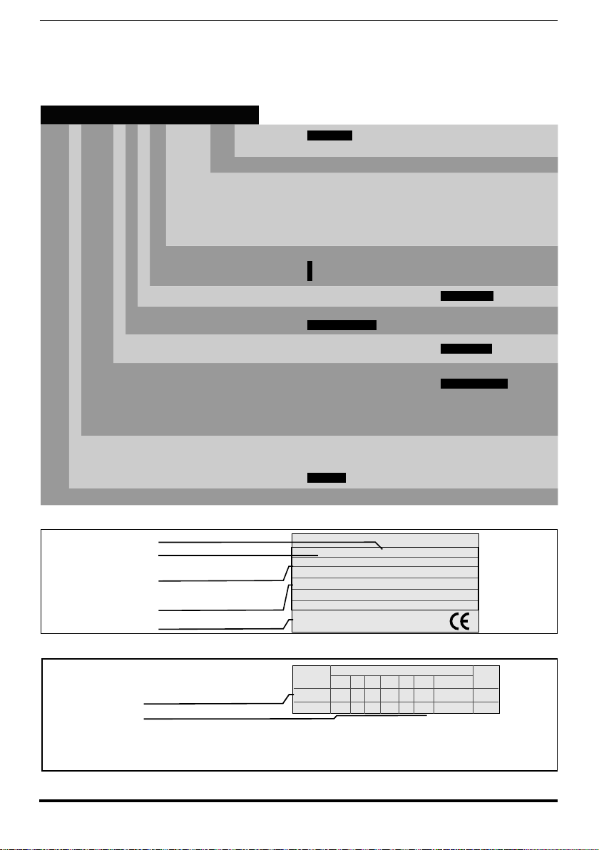
The main technical characteristic of the drive are showed in the product code and
in the nameplate. I.e. product code:
ADV 7 2000 -K X X -6 -XX YY -DC -SI
Safety card
EXP-SFTy-ADV included
DC bus power supply version
Parallel version only:
XX : MS = MASTER
SL = SLAVE
Rated voltage :
6 = 690 Vac (sizes 5 and 6)
6 = 500...690 Vac (sizes 7).
Software:
Braking unit:
X = non included
Keypad:
X = non included
Drive power, in kW:
750 = 75.0 kW
900 = 90.0 kW
1100 = 110.0 kW
1320 = 132.0 kW
1600 = 160.0 kW
Mechanical drive sizes:
5 = size 5
6 = size 6
7 = size 7
Drive ADV200 series
YY : 04 = 400.0 kW
05 = 500.0 kW
06 = 630.0 kW
07 = 710.0 kW
09 = 900.0 kW
10 = 1000.0 kW
X = standard
B = included
K = included
2000 = 200.0 kW
2500 = 250.0 kW
3150 = 315.0 kW
3550 = 355.0 kW
Identication Nameplate
Serial number
Drive model
Input (mains supply, frequency,AC Input
Current at constant torque)
Output (Output voltage, frequency, power,
current, CT and VT overloads)
Approvals
Type: ADV72000 -KXX-6 S/N: 07012345
Inp: 500Vac-10% 690Vac+10% 50/60Hz 3Ph
Out : 0-690Vac 200Hz 3Ph 200kW@690Vac 200Hp @ 575Vac
200kW 210A Ovld . 150%-60s
250kW 265A Ovld . 110%-60s
189
÷
A
Firmware & cards revision level nameplate
12 ADV200 • Quick start up guide - Specification and installation
Page 13

The inverter must be selected according to the rated current of the motor.
The rated output current of the drive must be higher than or equal to the rated current of the motor used.
The speed of the three-phase motor is determined by the number of pole pairs and
the frequency (nameplate, data sheet) of the motor concerned.
Operation above the rated frequency and speed of the motor must take into account the specications given by the manufacturer losses (bearings, unbalance
etc.). This also applies to temperature specications for continuous operation under
20 Hz (poor motor ventilation, not applicable to motors with external ventilation).
2.1.1 Parallel inverters
• Inverters of between 400 kW and 710 kW comprise one master and one
slave.
• Inverters of over 900 kW comprise one master and two slaves.
When placing your order please give the code number of the master and slave
and number of these:
Power code Description (Designation) Power code Description (Designation)
400kW
500kW
630kW
710kW
900kW
1000kW
S9O76M ADV-72000-KXX-6-MS 04 -SI
S9O76S ADV-72000-XXX-6-SL S9O76SC ADV-72000-KXX-6-SL-DC
S9O77M ADV-72500-KXX-6-MS 05 -SI
S9O77S ADV-72500-XXX-6-SL S9O77SC ADV-72500-KXX-6-SL-DC
S9O78M ADV-731500-KXX-6-MS 06 -SI
S9O78S ADV-731500-XXX-6-SL S9O78SC ADV-73150-KXX-6-SL-DC
S9O79M ADV-735500-KXX-6-MS 07 -SI
S9O79S ADV-735500-XXX-6-SL S9O79SC ADV-73550-KXX-6-SL-DC
S9O78M1 ADV-731500-KXX-6-MS 09 -SI
S9O78S ADV-731500-XXX-6-SL S9O78SC ADV-73150-KXX-6-SL-DC
S9O78S ADV-731500-XXX-6-SL S9O78SC ADV-73150-KXX-6-SL-DC
S9O79M1 ADV-735500-KXX-6-MS 10-SI
S9O79S ADV-735500-XXX-6-SL S9O79SC ADV-73550-KXX-6-SL-DC
S9O79S ADV-735500-XXX-6-SL S9O79SC ADV-73550-KXX-6-SL-DC
400kW
500kW
630kW
710kW
900kW
1000kW
S9O76MC ADV-72000-KXX-6-MS 04-DC- SI
S9O77MC ADV-72500-KXX-6-MS 05-DC-SI
S9O78MC ADV-73150-KXX-6-MS 06-DC-SI
S9O79MC ADV-73550-KXX-6-MS 07-DC-SI
S9O78M1C ADV-73150-KXX-6-MS 09-DC-SI
S9O79M1C ADV-73550-KXX-6-MS 10-DC-SI
630kW
710kW
900kW
1000kW
ADV200 • Quick start up guide - Specification and installation 13
S9O80M ADV-731500-KXX-6A-MS 06 -SI
S9O80S ADV-731500-XXX-6A-SL S9O80S ADV-73150-KXX-6A-SL-DC
S9O81M ADV-735500-KXX-6A-MS 07 -SI
S9O81S ADV-735500-XXX-6A-SL S9O81S ADV-73550-KXX-6A-SL-DC
S9O80M1 ADV-731500-KXX-6A-MS 09 -SI
S9O80S ADV-731500-XXX-6A-SL S9O80S ADV-73150-KXX-6A-SL-DC
S9O80S ADV-731500-XXX-6A-SL S9O80S ADV-73150-KXX-6A-SL-DC
S9O81M1 ADV-735500-KXX-6A-MS 10-SI
S9O81S ADV-735500-XXX-6A-SL S9O81S ADV-73550-KXX-6A-SL-DC
S9O81S ADV-735500-XXX-6A-SL S9O81S ADV-73550-KXX-6A-SL-DC
630kW
710kW
900kW
1000kW
S9O80M ADV-73150-KXX-6A-MS 06-DC-SI
S9O81M ADV-73550-KXX-6A-MS 07-DC-SI
S9O80M1 ADV-73150-KXX-6A-MS 09-DC-SI
S9O81M1 ADV-73550-KXX-6A-MS 10-DC-SI
Page 14

3 - Transport and storage
Correct transport, storage, erection and mounting, as well as careful operation and
maintenance are essential for proper and safe operation of the equipment.
Caution
Protect the inverter against physical shocks and vibration during transport and storage.
Also be sure to protect it against water (rainfall) and excessive temperatures.
Le bon accomplissement des opérations de transport, de stockage, d’installation et de montage, ainsi que l’exploitation et l’entretien minutieux, sont essentiels pour garantir à l’appareil
un fonctionnement adéquat et sûr.
If the Drives have been stored for longer than two years, the operation of the DC link
capacitors may be impaired and must be “reformed”. Before commissioning devices
that have been stored for long periods, connect them to a power supply for two hours
with no load connected in order to regenerate the capacitors, (the input voltage has to
be applied without enabling the drive).
En cas de stockage des variateurs pendant plus de deux ans, il est conseillé de contrôler
l’état des condensateurs CC avant d’en effectuer le branchement. Avant la mise en service
des appareils, ayant été stockés pendant long temps, il faut alimenter variateurs à vide pendant deux heures, pour régénérer les condensateurs : appliquer une tension d’alimentation
sans actionner le variateur.
3.1 General
A high degree of care is taken in packing the ADV Drives and preparing them for
delivery. They should only be transported with suitable transport equipment (see
weight data). Observe the instructions printed on the packaging. This also applieswhen the device is unpacked and installed in the control cabinet.
Upon delivery, check the following:
- the packaging for any external damage
- whether the delivery note matches your order.
Open the packaging with suitable tools. Check whether:
- any parts were damaged during transport
- the device type corresponds to your order
In the event of any damage or of an incomplete or incorrect delivery please notify
the responsible sales ofces immediately. The devices should only be stored in
dry rooms within the specied temperature ranges .
Note! A certain degree of moisture condensation is permissible if this arises from changes in temperature.
This does not, however, apply when the devices are in operation. Always ensure that there is no
moisture condensation in devices that are connected to the power supply!
14 ADV200 • Quick start up guide - Specification and installation
Page 15

Attention
3.2 Permissible Environmental Conditions
Temperature
storage �������������������� -25…+55°C (-13…+131°F), class 1K4 per EN50178
transport ������������������� -25…+70°C (-13…+158°F), class 2K3 per EN50178
Air humidity
storage �������������������� 5% to 95 %, 1 g/m3 to 29 g/m3 (class 1K3 as per EN50178)
transport ������������������� 95 % (3), 60 g/m3 (4)
A light condensation of moisture may occur for a short time occasionally if the device is not in operation
(class 2K3 as per EN50178)
Air pressure:
storage �������������������� [kPa] 86 to 106 (class 1K4 as per EN50178)
transport ������������������� [kPa] 70 to 106 (class 2K3 as per EN50178)
(3) Greatest relative air humidity occurs with the temperature @ 40°C (104°F) or if the temperature of the
device is brought suddenly from -25 ...+30°C (-13°...+86°F).
(4) Greatest absolute air humidity if the device is brought suddenly from 70...15°C (158°...59°F).
The drive is suitable for use under the environmental service conditions (climate,
mechanical, pollution, etc.) dened as usual service conditions according to
EN61800-2.
-20…+55°C (-4…+131°F), for devices with keypad
-20…+60°C (-4…+140°F), for devices with keypad
ADV200 • Quick start up guide - Specification and installation 15
Page 16

4 - Mechanical installation
The Drive must be mounted on a wall that is constructed of heat resistant material.
While the Drive is operating, the temperature of the Drive’s cooling ns can rise to a
Caution
temperature of 158° F (70°C).
Le drive doit être monté sur un mur construit avec des matériaux résistants à la chaleur.
Pendant le fonctionnement du drive, la température des ailettes du dissipateur thermique peut
arriver à 70°C (158° F).
Because the ambient temperature greatly affects Drive life and reliability, do not install
the Drive in any location that exceeds the allowable temperature.
Étant donné que la température ambiante inue sur la vie et la abilité du drive, on ne devrait
pasinstaller le drive dans des places ou la temperature permise est dépassée.
Be sure to remove the desicant dryer packet(s) when unpacking the Drive. (If not
removed these packets may become lodged in the fan or air passages and cause the
Drive to overheat).
Lors du déballage du drive, retirer le sachet déshydraté. (Si celui-ci n’est pas retiré, il empêche la ventilation et provoque une surchauffe du drive).
Protect the device from impermissible environmental conditions (temperature, humidity,
shock etc.).
Protéger l’appareil contre des effets extérieurs non permis (température, humidité, chocs etc.).
16 ADV200 • Quick start up guide - Specification and installation
Page 17
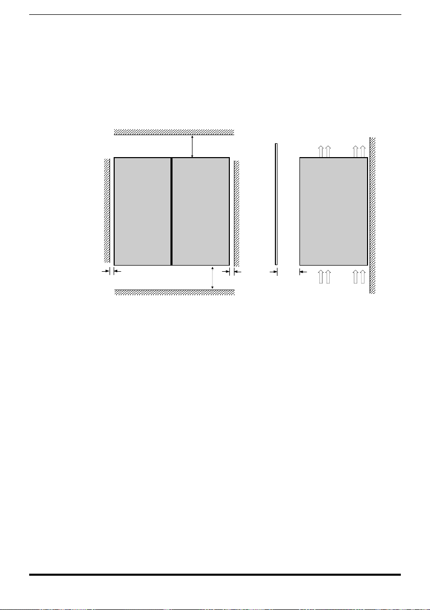
4.1 Inclination and mounting clearance
The Drives must be mounted in such a way that the free ow of air is ensured see
paragraph “9.9 Cooling”, page 136.
Maximum angle of inclination �����������30° (referred to vertical position)
Minimum top and bottom distance �������150 mm (≥ADV71600 = 400mm)
Minimum free space to the front ���������25 mm
Minimum distance between drives �������none
Minimum distance to the side with the cabinet
≥
150 mm [ 6" ]
400 mm [ 15.75" ] (ADV 7...)
≥
≥
10 mm [ 0.4" ]≥
150 mm [ 6" ]
≥400 mm [ 15.75" ] (ADV 7...)
10 mm
25 mm [ 0.98” ]≥10 mm [ 0.4" ]≥
ADV200 • Quick start up guide - Specification and installation 17
Page 18
200mm [7.87"]
100mm [3.93"]
A
A
400mm [15.75"]
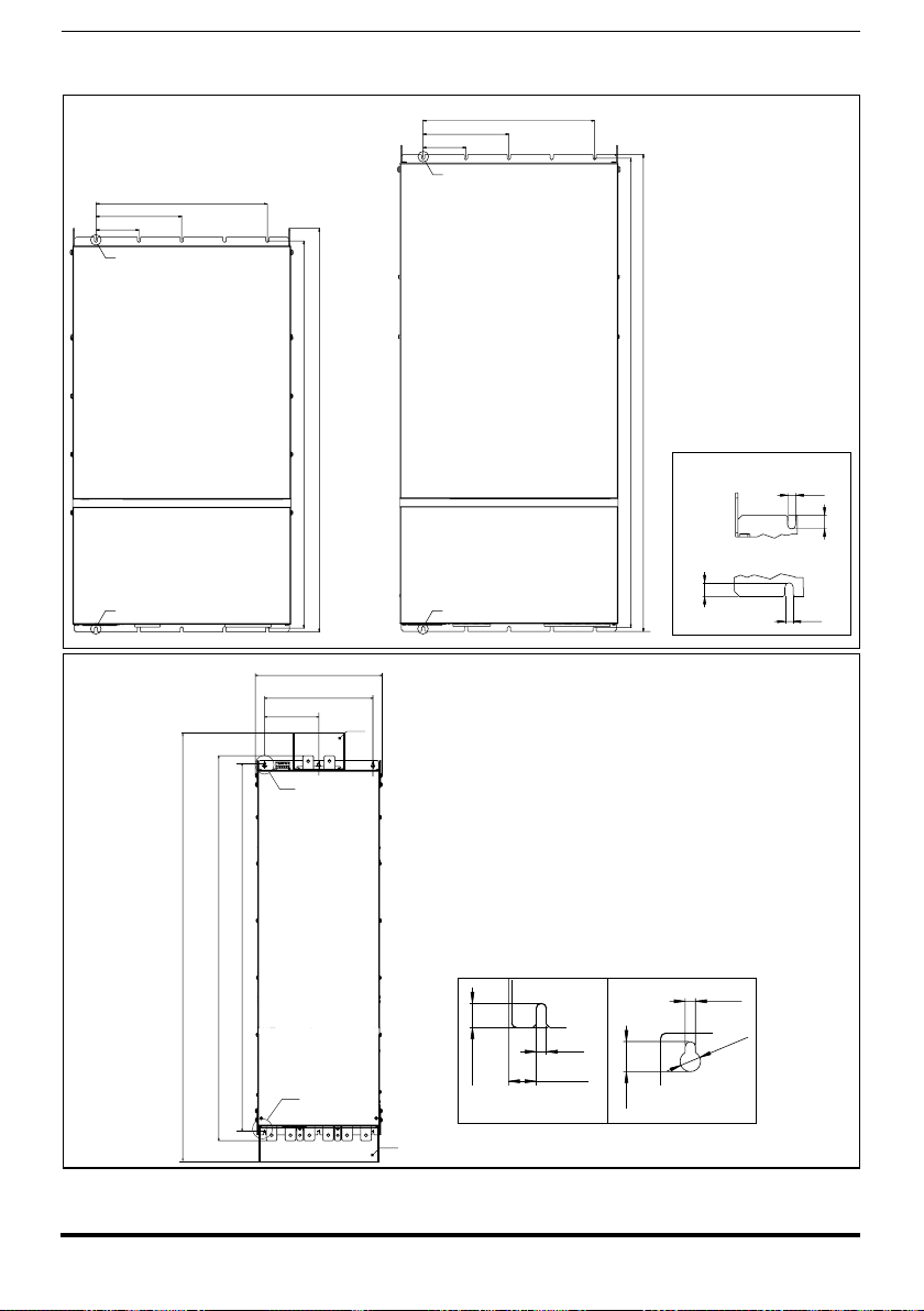
Taglia 5
Size 5
4.2 Fastening positions
100mm [3.93"]
A
942mm [37.08"]
904 mm [35.6"]
A
417 [16.42”]
355.6 [140”]
177.8 [7.00”]
(B)
(*)
200mm [7.87"]
Taglia 6
Size 6
400mm [15.75"]
Fissaggio a muro
Wall mounting
1113mm [43.82"]
1095mm [43.11"]
Fissaggio a muro
Wall mounting
A
12.75 mm
[.50"]
7.5 mm
[.295"]
7.5 mm
[.295"]
12.75 mm
[.50"]
[55.4”]
1407
[47.62”]
[49.76”]
1264
1209.5
Taglia 7
Size 7
(A)
(*) Protezione in policarbonato trasparente
(*) Protective trasparent policarbonate
6.5
[0.26”]
[0.6”]
17.45
[0.69”]
15.25
(A)
(*)
18 ADV200 • Quick start up guide - Specification and installation
6.5
[0.26”]
Ø 13
[0.51”]
19
[0.75”]
(B)
Page 19

Recommended screws for fastening
Size 5 (ADV 5...) 4 x M6 x 16 mm screws + Grover (spring-lock) washer + Flat washer
Size 6 (ADV 6...) 5 x M6 x 16 mm screws + Grover (spring-lock) washer + Flat washer
Size 7 (ADV 7...) 6 x M6 x 16 mm screws + Grover (spring-lock) washer + Flat washer
Note! Other dimensions see chapter “9.10 Weight and dimensions”, page 137.
ADV200 • Quick start up guide - Specification and installation 19
Page 20
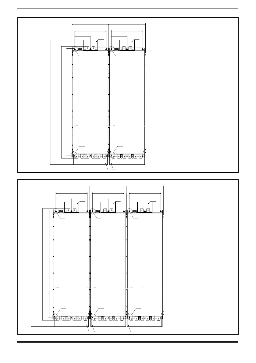
[55.4”]
1407
[47.62”]
[49.76”]
1264
1209.5
417 [16.42”]
355.6 [140”]
177.8 [7.00”]
(B)
417 [16.42”]
355.6 [140”]
177.8 [7.00”]
(*) (*)
(B)
Fissaggio a muro
Wall mounting
400 ... 710 kW
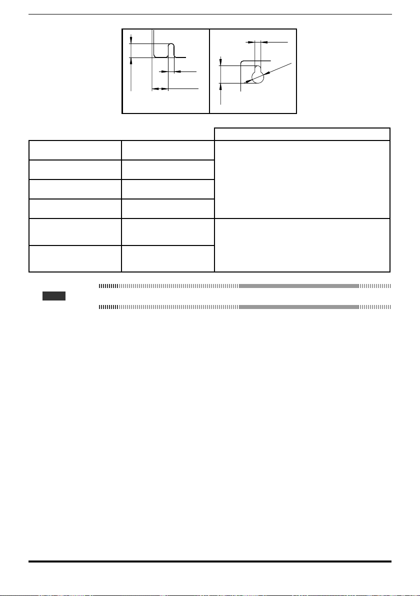
[55.4”]
1407
[47.62”]
[49.76”]
1264
1209.5
417 [16.42”]
355.6 [140”]
177.8 [7.00”]
(B)
(A)
(A)
(*)
417 [16.42”]
355.6 [140”]
177.8 [7.00”]
(B)
(A)
(A)
(*) Protezione in policarbonato trasparente
(*)
(*) Protective trasparent policarbonate
417 [16.42”]
355.6 [140”]
(*)
177.8 [7.00”]
(*)
Fissaggio a muro
Wall mounting
(B)
900 ... 1000 kW
(A)
(*) (*)
20 ADV200 • Quick start up guide - Specification and installation
(*) Protezione in policarbonato trasparente
(*) Protective trasparent policarbonate
Page 21
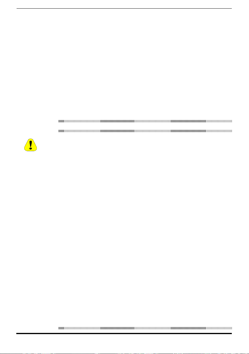
6.5
[0.26”]
6.5
[0.26”]
15.25
[0.6”]
17.45
[0.69”]
(A)
19
[0.75”]
(B)
Recommended screws for fastening
400 kW
500kW
630kW
710kW
900kW
1000kW
ADV-72000-KXX-6-MS 04 -SI
ADV-72000-XXX-6-SL
ADV-72500-KXX-6-MS 05 -SI
ADV-72500-XXX-6-SL
ADV-731500-KXX-6-MS 06 -SI
ADV-731500-XXX-6-SL
ADV-735500-KXX-6-MS 07 -SI
ADV-735500-XXX-6-SL
ADV-731500-KXX-6-MS 09 -SI
ADV-731500-XXX-6-SL
ADV-731500-XXX-6-SL
ADV-735500-KXX-6-MS 10-SI
ADV-735500-XXX-6-SL
ADV-735500-XXX-6-SL
12 x M6 x 16 mm screws + Grover (spring-lock) washer + Flat
washer
18 x M6 x 16 mm screws + Grover (spring-lock) washer + Flat
washer
Note! Other dimensions see chapter “9.10 Weight and dimensions”, page 137.
Ø 13
[0.51”]
ADV200 • Quick start up guide - Specification and installation 21
Page 22

5 - Wiring Procedure
Adjustable frequency drives are electrical apparatus for use in industrial installations.
Parts of the Drives are energized during operation. The electrical installation and the
Warning!
Warning!
opening of the device should therefore only be carried out by qualied personnel. Improper installation of motors or Drives may therefore cause the failure of the device as
well as serious injury to persons or material damage. Drive is not equipped with motor
overspeed protection logic other than that controlled by software. Follow the instructions
given in this manual and observe the local and national safety regulations applicable.
Les drives à fréquence variable sont des dispositifs électriques utilisés dans des installations
industriels. Une partie des drives sont sous tension pendant l’operation. L’installation électrique et l’ouverture des drives devrait être executé uniquement par du personel qualié. De
mauvaises installations de moteurs ou de drives peuvent provoquer des dommages materiels
ou blesser des personnes. On doit suivir les instructions donneés dans ce manuel et observer
les régles nationales de sécurité.
Replace all covers before applying power to the Drive. Failure to do so may result in
death or serious injury.
Remettre tous les capots avant de mettre sous tension le drive. Des erreurs peuvent provoquer de sérieux accidents ou même la mort.
The drive must always be grounded. If the drive is not connected correctly to ground,
extremely hazardous conditions may be generated that may result in death or serious
injury.
Le drive doit toujours être raccordé au système de mise à la terre. Un mauvais raccordement du drive au système de mise à la terre peut se traduire par des conditions extrêmement
dangereuses susceptibles d’entraîner le décès ou de graves lésions corporelles.
Never open the device or covers while the AC Input power supply is switched on. Minimum
time to wait before working on the terminals or inside the device is listed in section “9.8 Volt-
age level of the inverter for safe operations”, page 135.
Ne jamais ouvrir l’appareil lorsqu’il est suns tension. Le temps minimum d’attente avant de
pouvoir travailler sur les bornes ou bien à l’intérieur de l’appareil est indiqué dans la section
Voltage level of the inverter for safe operations”, page 135.
“9.8
Do not touch or damage any components when handling the device. The changing of
the isolation gaps or the removing of the isolation and covers is not permissible.
Manipuler l’appareil de façon à ne pas toucher ou endommager des parties. Il n’est pas
permis de changer les distances d’isolement ou bien d’enlever des matériaux isolants ou des
capots.
Do not connect power supply voltage that exceeds the standard specication voltage
uctuation permissible. If excessive voltage is applied to the Drive, damage to the
Caution
internal components will result.
Ne pas raccorder de tension d’alimentation dépassant la uctuation de tension permise par
les normes. Dans le cas d’ une alimentation en tension excessive, des composants internes
peuvent être endommagés.
Operation with Residual Current Device
If an RCD (also referred to as ELCB or RCCB) is tted, the inverters will operate without
nuisance tripping, provided that:
- a type B RCD is used.
- the trip limit of the RCD is 300mA.
22 ADV200 • Quick start up guide - Specification and installation
Page 23

- the neutral of the supply is grounded (TT or TN systems)
- only one inverter is supplied from each RCD.
- the output cables are less than 50m (screened) or 100m (unscreened).
RCD: Residual Current Device
RCCB: Residual Current Circuit Breaker
ELCB: Earth Leakage Circuit Breaker
Note: The residual current operated circuit-breakers used must provide protection
against direct-current components in the fault current and must be suitable for
briey suppressing power pulse current peaks. It is recommended to protect the
frequency inverter by fuse separately.
The regulations of the individual country (e.g. VDE regulations in Germany) and
the regional power suppliers must be observed!
Fonctionnement avec un dispositif de courant résiduel
En cas d’installation d’un RCD – dispositif de courant résiduel – (également dénommé RCCB
ou ELCB), les onduleurs fonctionneront sans faux arrêt à condition que :
- le RCD utilisé soit de type B
- le seuil de déclenchement du RCD soit xé à 300 mA
- le neutre du bloc d’alimentation soit mis à la terre (systèmes TT ou TN)
- chaque RCD n’alimente qu’un seul onduleur
- la longueur des câbles de sortie soit inférieure à 50 m (blindés) ou 100 m (non blindés)
RCD: Dispositif de courant résiduel
RCCB: Disjoncteur à courant résiduel
ELCB: Disjoncteur contre fuite à la terre
Remarque : Les RCD utilisés doivent assurer la protection contre les composants à courant
Respecter la réglementation des pays concernés (par exemple, les normes VDR
continu présents dans le courant de défaut et doivent être capables de supprimer des crêtes de courant en peu de temps. Il est recommandé de protéger
séparément l’onduleur au moyen de fusibles.
en Allemagne) et des fournisseurs locaux d’énergie électrique.
Functioning of the Drive without a ground connection is not permitted. To avoid disturbances, the armature of the motor must be grounded using a separate ground connec-
Caution
tor from those of other appliances.
Défense de faire fonctionner le drive sans qu’il y ait eu raccordement de mise à la terre préalable. Pour éviter les perturbations, la carcasse du moteur doit être mise à la terre à l’aide d’un
raccord de mise à la masse séparé de ceux des autres appareils.
The grounding connector shall be sized in accordance with the NEC or Canadian Electrical Code. The connection shall be made by a UL listed or CSA certied closed-loop
terminal connector sized for the wire gauge involved. The connector is to be xed using
the crimp tool specied by the connector manufacturer.
Le raccordement devrait être fait par un connecteur certié et mentionné à boucle fermé par
lesnormes CSA et UL et dimensionné pour l’épaisseur du cable correspondant. Le connecteur
doit êtrexé a l’aide d’un instrument de serrage specié par le producteur du connecteur.
Do not perform a megger test between the Drive terminals or on the control circuit terminals.
Ne pas exécuter un test megger entre les bornes du drive ou entre les bornes du circuit de contrôle.
No voltage should be connected to the output of the drive (terminals U2, V2 W2). The
parallel connection of several drives via the outputs and the direct connection of the
inputs and outputs (bypass) are not permissible.
Aucune tension ne doit être appliquée sur la sortie du convertisseur (bornes U2, V2 et W2). Il
n’est pas permis de raccorder la sortie de plusieurs convertisseurs en parallèle, ni d’effectuer
une connexion directede l’entrée avec la sortie du convertisseur (Bypass).
ADV200 • Quick start up guide - Specification and installation 23
Page 24
Caution
The electrical commissioning should only be carried out by qualied personnel, who
are also responsible for the provision of a suitable ground connection and a protected
power supply feeder in accordance with the local and national regulations. The motor
must be protected against overloads.
La mise en service électrique doit être effectuée par un personnel qualié. Ce dernier est
responsable del’existence d’une connexion de terre adéquate et d’une protection des câbles
d’alimentation selon les prescriptions locales et nationales. Le moteur doit être protégé contre
la surcharge
If the Drives have been stored for longer than two years, the operation of the DC link
capacitors may be impaired and must be “reformed”. Before commissioning devices
that have been stored for long periods, connect them to a power supply for two hours
with no load connected in order to regenerate the capacitors, (the input voltage has to
be applied without enabling the drive).
En cas de stockage des variateurs pendant plus de deux ans, il est conseillé de contrôler
l’état des condensateurs CC avant d’en effectuer le branchement. Avant la mise en service
des appareils, ayant été stockés pendant long temps, il faut alimenter variateurs à vide pendant deux heures, pour régénérer les condensateurs : appliquer une tension d’alimentation
sans actionner le variateur.
Type of networks
ADV200-6 drives are designed to be powered from standard three phase lines that are
electrically symmetrical with respect to ground (TN or TT network). In case of supply
with IT network, sizes ≥ 71600 (with integrated EMI lter and max. distance of 50 m
between inverter and motor) can be used.
For sizes < 71600, the use of the “ADV200….-IT” series is mandatory.
ADV200...-IT does not include the use of an EMI lter with internal capacitors connected to
the ground. The RFI emissions level are more relevant but in accordance with EN 61800-3.
In case of limited emission levels requirements, it is suggested to check for excessive
noise from close electrical equipment or to the public low-voltage mains. If necessary,
to reduce the levels of emissions is enought to use a voltage transformer with static
screening between the primary and secondary windings.
Do not install an external EMI lter to the ADV200-6. Capacitors inside the lter
could be damaged and could cause safety problem.
Type de réseaux :
Les variateurs ADV200-6 sont conçus pour être alimentés à partir des lignes triphasées
standard qui sont électriquement symétrique par rapport à la terre (TN ou réseau TT).
En cas d’alimentation avec le réseau IT, les tailles ≥ 71600 (avec ltre EMI intégré et
une distance maxima le de 50 m entre le variateur et le moteur) peuvent être utilisés.
Pour les tailles <71600, la référence «ADV200 ....-IT» est obligatoire.
“ADV200...-IT’’ n’inclut pas l’utilisation d’un ltre EMI avec des condensateurs internes
reliés à la masse. Le niveau des émissions de RFI sont plus pertinentes, mais en conformité avec la norme EN 61800-3.
En cas de besoins pour limités les niveaux d’émission, il est suggéré de vérier le bruit
excessif provenant des équipements électriques à proximité ou sur le réseau basse
tension . Si nécessaire, pour réduire les niveaux d’émissions trop important utiliser un
transformateur d’isolement entre les enroulements primaires et secondaires.
Ne pas installer un ltre EMI externe à l’ADV200-6. Les condensateurs à l’intérieur
du ltre pourraient être endommagés et pourraient causer des problèmes de
sécurité.
24 ADV200 • Quick start up guide - Specification and installation
Page 25
5.1 Power section
5.1.1 Cable Cross Section
Terminals: U1/L1 - V1/L2 - W3/L3 - C - D - U2/T1 - V2/T2 - W2/T3
Sizes
5750 50 1/0 16 3.2
6900 70 2/0 24 3.5
61100 70 2/0 24 3.5
61320 70 2/0 24 3.5
5750 35 2 15 3.2
6900 35 2 18 5
61100 35 2 18 5
61320 35 2 18 5
Sizes
5750 4 10 10 0.5
6900 4 10 10 0.5
61100 4 10 10 0.5
61320 4 10 10 0.5
Sizes
71600 95 AWG 4/0 M10 50
72000 150 300 kcmil M10 50
72500 240 500 kcmil M10 50
73150 2 x 100 2 x AWG 4/0 M10 50
73550 2 x 100 2 x AWG 4/0 M10 50
Maximum Cable Cross Section (flexible conductor) Recommended stripping Tightening torque (min)
(mm2) AWG (mm) (Nm)
Morsetti: PE1 - PE2
Terminals: U3 - 2V3 - 1V3
Maximum Cable Cross Section (flexible conductor) Recommended stripping Tightening torque (min)
(mm2) AWG (mm) (Nm)
Bars: L1 - L2 - L3 - C - D - U - V - W
Recommended Cable Cross Section Lock screw diameter Tightening torque (min)
(mm2) AWG / kcmil (mm) (Nm)
diameter
on bars
Recommended
terminal
Tightening torque
Connection
Sizes
71600 50 AWG 1/0 M10 Eyelet 50
72000 75 AWG 2/0 M10 Eyelet 50
72500 120 250 kcmil M10 Eyelet 50
73150 150 300 kcmil M10 Eyelet 50
73550 150 300 kcmil M10 Eyelet 50
ADV200 • Quick start up guide - Specification and installation 25
Cable Cross Section Lock screw
(mm2) AWG / kcmil (mm) (mm) (Nm)
Page 26
400kW
500kW
630kW
710kW
900kW
1000kW
400kW
500kW
630kW
710kW
900kW
1000kW
Bars: L1 - L2 - L3 - C - D - U - V - W
Sizes
ADV-72000-KXX-6-MS 04-...
ADV-72000-XXX-6-SL-...
ADV-72500-KXX-6-MS 05-...
ADV-72500-XXX-6-SL-...
ADV-731500-KXX-6-MS 06-...
ADV-731500-XXX-6-SL-...
ADV-735500-KXX-6-MS 07-...
ADV-735500-XXX-6-SL-...
ADV-731500-KXX-6-MS 09-...
ADV-731500-XXX-6-SL -...
ADV-731500-XXX-6-SL -...
ADV-735500-KXX-6-MS 10-...
ADV-735500-XXX-6-SL -...
ADV-735500-XXX-6-SL -...
Sizes
ADV-72000-KXX-6-MS 04-...
ADV-72000-XXX-6-SL-...
ADV-72500-KXX-6-MS 05-...
ADV-72500-XXX-6-SL-...
ADV-731500-KXX-6-MS 06-...
ADV-731500-XXX-6-SL-...
ADV-735500-KXX-6-MS 07-...
ADV-735500-XXX-6-SL-...
ADV-731500-KXX-6-MS 09-...
ADV-731500-XXX-6-SL -...
ADV-731500-XXX-6-SL -...
ADV-735500-KXX-6-MS 10-... 150 300 kcmil M10 Eyelet 50
ADV-735500-XXX-6-SL -...
ADV-735500-XXX-6-SL -...
Recommended cable cross-section Lock screw
(mm2) AWG / kcmil (mm) (Nm)
150 300 kcmil M10 50
150 300 kcmil M10 50
240 500 kcmil M10 50
240 500 kcmil M10 50
2 x 100 2 x AWG 4/0 M10 50
2 x 100 2 x AWG 4/0 M10 50
2 x 100 2 x AWG 4/0 M10 50
2 x 100 2 x AWG 4/0 M10 50
2 x 100 2 x AWG 4/0 M10 50
2 x 100 2 x AWG 4/0 M10 50
2 x 100 2 x AWG 4/0 M10 50
2 x 100 2 x AWG 4/0 M10 50
2 x 100 2 x AWG 4/0 M10 50
2 x 100 2 x AWG 4/0 M10 50
Connection
Recommended cable
cross-section
(mm2) AWG / kcmil (mm) (mm) (Nm)
75 AWG 2/0 M10 Eyelet 50
75 AWG 2/0 M10 Eyelet 50
120 250 kcmil M10 Eyelet 50
120 250 kcmil M10 Eyelet 50
150 300 kcmil M10 Eyelet 50
150 300 kcmil M10 Eyelet 50
150 300 kcmil M10 Eyelet 50
150 300 kcmil M10 Eyelet 50
150 300 kcmil M10 Eyelet 50
150 300 kcmil M10 Eyelet 50
150 300 kcmil M10 Eyelet 50
150 300 kcmil M10 Eyelet 50
150 300 kcmil M10 Eyelet 50
Lock screw
diameter
Recommended
diameter
stripping
Tightening torque
(min)
Tightening
torque (min)
26 ADV200 • Quick start up guide - Specification and installation
Page 27

Attention
5.1.2 EMC guide line
Drives are designed to operate in an industrial environment where a high level
of electromagnetic interference are to be expected. Proper installation practices
will ensure safe and trouble-free operation. If you encounter problems, follow the
guidelines which follow.
- Check for all equipment in the cabinet are well grounded using short, thick
grounding cable connected to a common star point or busbar. Better solution
is to use a conductive mounting plane and use that as EMC ground reference
plane.
- Flat conductors, for EMC grounding, are better than other type because they
have lower impedance at higher frequencies.
- Make sure that any control equipment (such as a PLC) connected to the
inverter is connected to the same EMC ground or star point as the inverter via
a short thick link.
- Connect the return ground from the motors controlled by the drives directly to
the ground connection (
) on the associated inverter.
- Separate the control cables from the power cables as much as possible, using
separate trunking, if necessary at 90º to each other.
- Whenever possible, use screened leads for the connections to the control
circuitry
- Ensure that the contactors in the cubicle are suppressed, either with R-C
suppressors for AC contactors or ‘ywheel’ diodes for DC contactors tted to
the coils. Varistor suppressors are also effective. This is important when the
contactors are controlled from the inverter relay .
- Use screened or armored cables for the motor connections and ground the
screen at both ends using the cable clamps
Note! For further information regarding electro-magnetic compatibility standards, according to Directive
89/336/EEC, conformity checks carried out on Gefran appliances, connection of filters and mains
inductors, shielding of cables, ground connections, etc., consult the “Electro-magnetic compatibility
guide” on the CD attached to this drive.
ADV200 • Quick start up guide - Specification and installation 27
Page 28
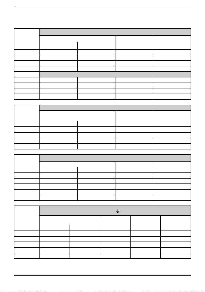
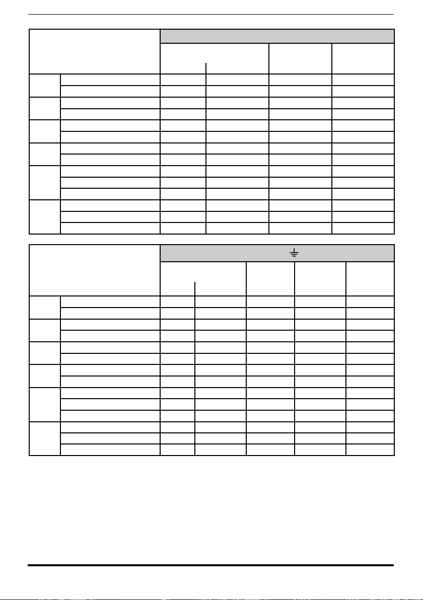
5.1.3 Block diagram power section
L1
L2
L3
C
D
LDC
U
V
W
R PRECHARGE
LINE
690Vac, 3ph
L1
L2
L3
C
D
U
V
W
LINE
500-690Vac, 3ph
C
D
U
V
W
CDC LINK
600 - 1120 Vdc
L1
L2
L3
C
D
U
V
W
ADV- ...- MS..-6
L1
L2
L3
C
D
U
V
W
Input
fuse
Input choke
(mandatory)
Input
fuse
Input choke
(mandatory)
ADV- ...- SL..-6
Output choke
(mandatory)
Output choke
(mandatory)
U
V
W
To motor
LINE
500-690Vac, 3ph
C
D
U
V
W
ADV- ...- MS..-6-DC
C
D
U
V
W
600 - 1120 Vdc
Input
fuse
Input
fuse
ADV- ...- SL..-6-DC
Output choke
(mandatory)
Output choke
(mandatory)
U
V
W
To motor
ADV5750-...-6 ... ADV61320-...-6
ADV71600-...-6... ADV73550-...-6
ADV71600-...-6-DC ... ADV73550-...-6-DC
400 ... 710kW (ADV200-...-6)
400 ... 710kW (ADV200-...-6-DC)
28 ADV200 • Quick start up guide - Specification and installation
Page 29
900 ... 1000kW (ADV200-...-6)
L1
L2
L3
C
D
U
V
W
ADV- ...- MS..-6
L1
L2
L3
C
D
U
V
W
Input
fuse
Input choke
(mandatory)
Input
fuse
Input choke
(mandatory)
ADV- ...- SL..-6
Output choke
(mandatory)
Output choke
(mandatory)
U
V
W
To motor
L1
L2
L3
C
D
U
V
W
Input
fuse
Input choke
(mandatory)
ADV- ...- SL..-6
Output choke
(mandatory)
LINE
500-690Vac, 3ph
C
D
U
V
W
ADV- ...- MS..-6-DC
C
D
U
V
W
Input
fuse
Input
fuse
ADV- ...- SL..-6-DC
Output choke
(mandatory)
Output choke
(mandatory)
U
V
W
To motor
C
D
U
V
W
Input
fuse
ADV- ...- SL..-6-DC
Output choke
(mandatory)
600 - 1120 Vdc
900 ... 1000kW (ADV200-...-6-DC)
Note! Size 7 only: pre-engineered for internal assembly of DC side fuses upon request.
ADV200 • Quick start up guide - Specification and installation 29
5.1.4 Internal EMC lter
ADV200 series inverters are equipped with an internal EMI (except ADV200-...-DC
models) lter able to guarantee the performance levels required by EN 61800-3
standard (according to 2nd environment, category C3) with a maximum of 20
meters of shielded motor cable (up to 50 metres for size 5 and above).
Page 30
ADV5750-6 ... ADV61320-6
5.1.5 Power line connection
PE1
L1 L2 L3
K1M
F1
ADV71600-6 ... ADV73550-6
L1 L2 L3
( 690 50/60 Hz)3ph - V
AC,
C D
L1 L2 L3 U V W
L1
K1M
F1
L1 L2 L3
( 500 ... 690 50/60 Hz)3ph - VAC,
30 ADV200 • Quick start up guide - Specification and installation
Page 31

ADV71600-...-6-DC ... ADV73550-...-6-DC
DC - 600 - 1120 VDC
F1
K1M
C D
400 ... 710 kW (ADV200-...-6)
U V W
C D
ADV-...-MS..-6 ADV-...-SL-6
L1 L2 L3 U V W
L1
Mandatory
L1 L2 L3 U V W
F1
K1M
L1 L2 L3
( 500 ...690 50/60 Hz)3ph - VAC,
C D
L1
Mandatory
F1
ADV200 • Quick start up guide - Specification and installation 31
Page 32

400 ... 710 kW (ADV200-...-6-DC)
(600 ... 1120 )VDC
K1M
F1F1
900 ... 1000 kW (ADV200-...-6)
C D
ADV-...-MS..-6-DC ADV-...-SL-6-DC
C D
L1 L2 L3 U V W
L1
Mandatory
F1
U V W
C D
ADV-...-MS-..ADV-...-SL
L1 L2 L3 U V W
L1
Mandatory
F1
C D
U V W
L1 L2 L3 U V W
C D
ADV-...-SL
L1
Mandatory
F1
K1M
(3ph - 500 ...690 V 50/60 Hz)AC,
L1 L2 L3
32 ADV200 • Quick start up guide - Specification and installation
Page 33

900 ... 1000 kW (ADV200-...-6-DC)
(600 ... 1120 )VDC
K1M
C D
ADV-...-MS..-6-DC
U V W
F1F1
C D
ADV-...-SL-6-DC
U V W
F1
C D
ADV-...-SL-6-DC
U V W
Note! Recommended combination F1 fuses: see paragraph “10.1 Optional external fuses”, page 141.
5.1.6 Input mains choke (L1)
Sizes ADV5750-6 ... 61320-6: Integrated on DC-link.
Sizes ADV71600-6 ... and above: external choke mandatory (for the recommend-
ed combination see chapter
Sizes ADV-...-DC: not available.
“10.2 Choke”, page 144.
ADV200 • Quick start up guide - Specification and installation 33
Page 34

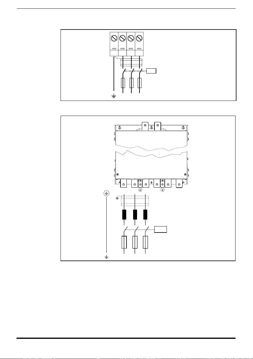
5.1.7 Motor connection
M
3 ph
L1 L2 L3 U V W
ADV-...-MS-.. ADV-...-SL
Output choke
or current-sharing
choke (mandatory)
Output choke
or current-sharing
choke (mandatory)
ADV5750-6 ... ADV61320-6
2V3
U3
1V3
C D U2 V2 W2 PE2
M
3 ph
ADV71600-6 ... ADV73550-6, ADV71600-6-DC ... ADV73550-6-DC
L1 L2 L3 U V W
M
3 ph
Nota: terminals L1-L2 and L3 are not present in -DC versions.
400 ... 710 kW (ADV200-...-6 e ADV200-...-6-DC)
L1 L2 L3 U V W
Nota: terminals L1-L2 and L3 are not present in -DC versions.
34 ADV200 • Quick start up guide - Specification and installation
Page 35

900 ... 1000 kW (ADV200-...-6 e ADV200-...-6-DC)
M
3 ph
L1 L2 L3 U V W
ADV-...-MS..ADV-...-SL
L1 L2 L3 U V W
ADV-...-SL
Output choke
or current-sharing
choke (mandatory)
Output choke
or current-sharing
choke (mandatory)
Output choke
or current-sharing
choke (mandatory)
L1 L2 L3 U V W
Note: terminals L1-L2 and L3 are not present in -DC versions.
5.1.8 Braking unit connection (optional)
Note! An optional BUy braking unit connected to terminals C and D can be used. For further details reference
should be made to the BUy manual.
ADV200 • Quick start up guide - Specification and installation 35
Page 36

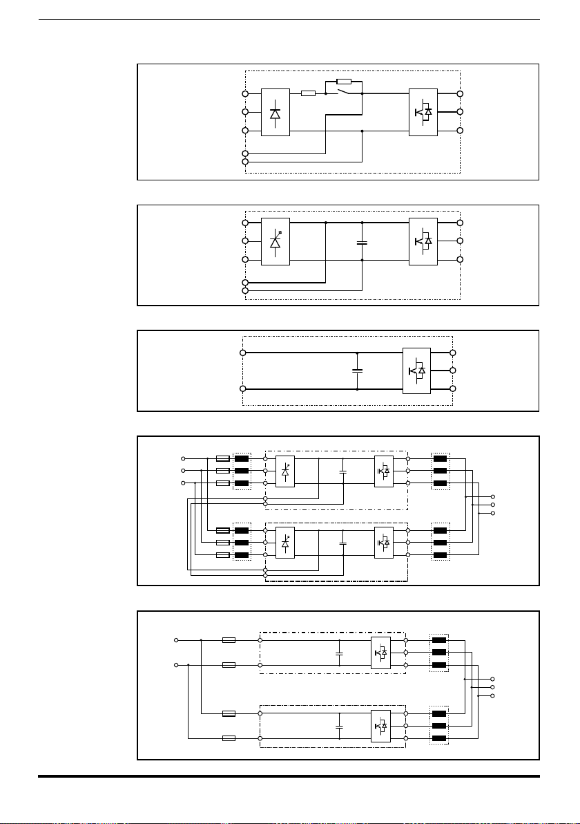
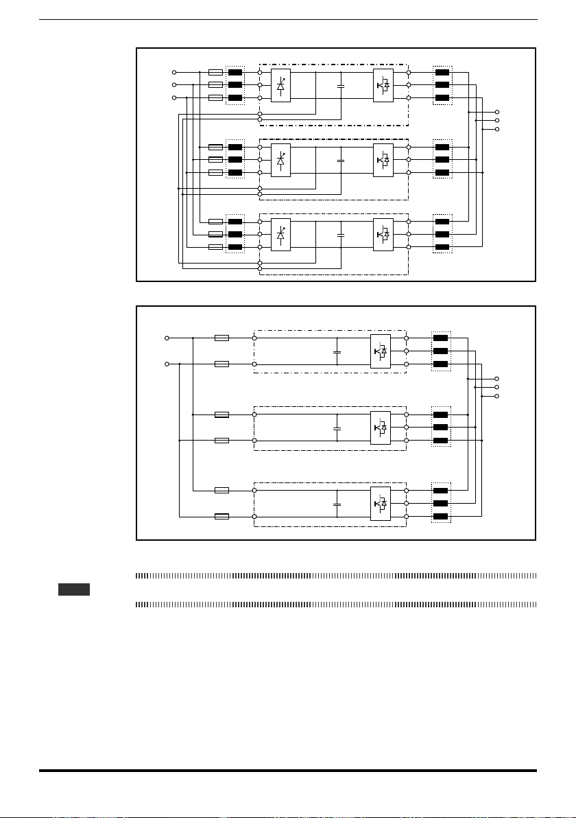
5.1.9 Parallel connection on the AC (Input) and DC (Intermediate Circuit) side
M1
3
M2
3
M6
3
F11
F21
F61
L1
L2
L3
U
V
W
C
D
INVERTER 1
L1
L2
L3
U
V
W
C
D
INVERTER 2
BR1
F12
F22
F62
L1
L2
L3
U
V
W
C
D
INVERTER 6
BR
CR
C
D
B y-...U
(MASTER)
7 8 9 10
R
BR
R
BR
L1
L2
L3
K1
M..
3
F..
L1
L2
L3
U
V
W
C
D
INVERTER ..
F..
(*)
BR2
of several inverters
- The inverters used have to be all the same size.
- The mains power supply has to be simultaneous for all inverters, i.e. a single switch /line contactor has
- Such connection is suitable for a maximum of 6 inverters.
- If necessary dissipate braking energy; one (or several) external braking unit has to be used.
- Fast fuses (F12...F62) have to be tted on the dc-link side ( C and D terminals) of each inverters (see
to be used.
chapter “10.1 Optional external fuses”, page 141).
(*) Do not connect if external braking units BUy.. is used.
(*)Pasraccordersil’unitédefreinageextérieureBUy...estutilisée
Caution
36 ADV200 • Quick start up guide - Specification and installation
Page 37

Caution
5.1.10 Parallel DC connection
In the case of DC power supply, insertion of an AC mains inductance on the power
supply input of the power supply unit is compulsory (for the type of inductance,
consult the manual of the power supply unit).
To aviod to damnage the internal EMI lter, regenerative converters may not supply the DC power supply to ADV1007 ...ADV61320 drives.
Regenerative converters may supply the DC power supply to the ADV200 (≥
71600) and ADV200-...-DC series.
( 500 V / 690 50/60 Hz)
3ph - V
F1 (*)
L1
AC
L2
AC
L3
,
K1M
(*) Refer to AFE200, SM32 or DC Power supply manual.
AFE200, SM32 or
DC Power supply
L1 (*)
F12
C
D
ADV200-...-6 (1)
F22
C
D
ADV200 (2)-...-6
F32
C
D
ADV200 (3)-...-6
F..2
C
D
ADV200 (..)-...-6
U
V
W
U
V
W
U
V
W
U
V
W
M1
3
M2
3
M3
3
M..
3
Nota! Solo taglia 7: a richiesta predisposizione per montaggio interno fusibili “F12, F22, F32, F.2” (lato DC).
ADV200 • Quick start up guide - Specification and installation 37
Page 38

5.1.11 Connection of fans
Sizes
5750
6900
61320
Terminals
U3 2V3 1V3
0.8A@115V/60Hz,
0.45A@230V / 50Hz
UL-type fan connection:
Example for External Connection
M
~
230VAC
2V3
1V3
U3
Drive
No.2 115VAC fans
M
~
1.2A@115V/60Hz,
0.65A@230V / 50Hz
UL-type fan connection:
Drive
U3
2V3
1V3
0
115
230
M
~
AUTOTRAFO
230VAC fans
Example for External Connection
230VAC
Drive Drive
U3
115VAC
2V3
1V3
Drive
U3
115VAC
2V3
1V3
U3
2V3
1V3
Drive
U3
2V3
1V3
NB ! Size 621320 is provided with 2.5 A, 250 Vac internal slo-blo fuses.
External fuses must be used for sizes 5750 and 6900.
38 ADV200 • Quick start up guide - Specification and installation
Page 39

Sizes
Version before 2009/125/CE (ErP regulation)
Terminals
U3 V3 PE 31 32
250V/10A contact
1 x 230V / 50/60Hz,
2.4A (50Hz) - 3.3A
(60Hz)
Motor over temperature contact management terminals 31-32:
Closed: Internal fan in operation and powered;
Ground
Open: Internal fan in over temperature alarm and/or input power supply
not available.
Power the internal fan (max 600W) with a single-phase voltage on terminals U3/V3.
71600 ... 72500
Type of fan compliant 2009/125/CE (ErP)
ADV200 starting from S/N 33GC017331
U3 V3 W3 PE 31 32
3 x 400V / 50/Hz,
1.15Arms ... 3
x 460V / 60Hz,
Ground
1.4Arms
Power the internal fan ( 570W @400V, 930W @460V ) with a three-phase voltage on terminals U3/V3/W3.
Sizes
U3 V3 W3 PE 31 32
3 x 400V / 50Hz,
1,55Arms
73150 ... 73550
or
3 x 460V / 60Hz,
Ground
1,7Arms (*)
Power the internal fan (max 1200W) with a three-phase voltage on terminals U3/V3/W3.
(*) ADV200-73150-KXX-6A and ADV200-73550-KXX-6A models.
Terminals
250V/2A contact
Motor over temperature contact management terminals 31-32:
Closed: Internal fan in operation
Open: Internal fan in over temperature alarm
Terminals
250V/10A contact
Motor over temperature contact management terminals 31-32:
Closed: Internal fan in operation
Open: Internal fan in over temperature alarm
ADV200 • Quick start up guide - Specification and installation 39
Page 40

Sizes
Version before 2009/125/CE (ErP regulation)
Terminals
U3 V3 PE 31 32
250V/10A contact (x 2)
1 x 230V / 50/60Hz,
2.4A (50Hz) - 3.3A
(60Hz)
(x 2)
Power the internal fan (max 600W) with a single-phase voltage on terminals U3/V3. ( x 2).
Motor over temperature contact management terminals 31-32:
Ground
Closed: Internal fan in operation and powered;
Open: Internal fan in over temperature alarm and/or input power supply
not available.
400 kW
500 kW
U3 V3 W3 PE 31 32
3 x 400V / 50/Hz,
1.15Arms ... 3
x 460V / 60Hz,
1.4Arms
(x 2)
Power the internal fan ( 570W @400V, 930W @460V ) with a three-phase voltage on terminals U3/V3/
W3 (x 2).
Sizes
630 kW
710 kW
900 kW
1000 kW
(*) ADV200-73150-KXX-6A and ADV200-73550-KXX-6A models.
U3 V3 W3 PE 31 32
3 x 400V / 50Hz,
1,55Arms (x 2)
or
3 x 460V / 60Hz,
1,7Arms (x 2) (*)
Power the internal fan (max 1200W) with a three-phase voltage on terminals U3/V3/W3. (x 2).
3 x 400V / 50Hz,
1,55Arms (x 3)
or
3 x 460V / 60Hz,
1,7Arms (x 3) (*)
Power the internal fan (max 1200W) with a three-phase voltage on terminals U3/V3/W3 (x 3).
Type of fan compliant 2009/125/CE (ErP)
ADV200 starting from S/N 33GC017331
Ground
Ground
Ground
Terminals
250V/2A contact (x 2)
Motor over temperature contact management terminals 31-32:
Closed: Internal fan in operation
Open: Internal fan in over temperature alarm
Terminals
250V/10A contact (x 2)
Motor over temperature contact management terminals 31-32:
Closed: Internal fan in operation
Open: Internal fan in over temperature alarm
250V/10A contact (x 3)
Motor over temperature contact management terminals 31-32:
Closed: Internal fan in operation
Open: Internal fan in over temperature alarm
Make sure the sequence of the three-phase fan power supply phases is the same as that shown on
the relative drive terminals. If not, the air flow will be inadequate to ensure correct cooling..
Caution
40 ADV200 • Quick start up guide - Specification and installation
Page 41

Warning!
Terminal strips
(Regulation card)
5.2 Regulation section
5.2.1 Removing the terminal cover
When removing the covers be carefull to lateral metal sheet enclosure. Presence of
sharp edge are possible.
A
A
5.2.2 Cable Cross Section
Maximum Cable Cross Section Recommended
stripping
(mm2) (AWG) (mm) (Nm)
0.2 ... 2.5 24 ... 12 7 0.5
Tightening torque (min)
(min)
5.2.3 Regulation section connection
Figure 5.2.3.1: Regulation shielding
For shielding of the regulation section (recommended), fasten the shield of the
cables to the omega sections (see gure above).
ADV200 • Quick start up guide - Specification and installation 41
Page 42

Table 5.2.3.1: Regulation terminals
Strip T2 (top)
Terminal Designation Function Max
R21 COM Digital output 2 Common reference for digital output 2 (Relay 2) -
R24 Digital output 2 Programmable digital relay output 2 (NO). Default = Drive ready 250 Vac - 30 Vdc / 2A
5 Analog output 1 Analog output 1. Default = Null (not assigned) ±12,5 V (typical ±10 V / 5 mA)
- voltage (default):
±12,5 V (typical ±10V/5mA)
6 Analog output 2 Analog output 2. Default = Null (not assigned)
C1 COM Analog output Common reference for analog outputs and ±10V potential voltage reference -
7 Digital input E Digital input E . Default = Digital input E mon (Enable) 5mA @ +24V (+30V max)
8 Digital input 1 Digital input 1 . Default = FR forward src, PAR 1042 5mA @ +24V (+30V max)
9 Digital input 2 Digital input 2 . Default = FR reverse src, PAR 1044 5mA @ +24V (+30V max)
10 Digital input 3 Digital input 3 . Default = Multi ref sel 0 src 5mA @ +24V (+30V max)
11 Digital input 4 Digital input 4 . Default = Multi ref sel 1 src 5mA @ +24V (+30V max)
12 Digital input 5 Digital input 5 . Default = Fault reset src 5mA @ +24V (+30V max)
C2 COM Digital inputs Common reference for digital inputs -
C3 0V 24 OUT Reference point for +24V OUT -
S3 + 24V OUT +24V supply for IO 150 mA (Resettable fuse), ±10 %
Strip T1 (bottom)
Terminal Designation Function Max
R11 COM Digital output 1 Common reference for digital output 1 (Relay 1) -
R14 Digital output 1 Programmable digital relay output 1 (NO). Default = Drive OK 250 Vac - 30 Vdc / 2A
1
Analog input 1
2
3
Analog input 2
4
S1+ +10 V Voltage reference +10V; reference point: C1 terminal +10 V ±1% / 10 mA
S1- - 10V Analog output -10V; reference point: C1 terminal -10 V ±1% / 10 mA
13 Digital output 3 Digital output 3. Default = Speed is 0 delay +24 V / 20 mA (typ), 40 mA (max)
14 Digital output 4 Digital output 4. Default = Ref is 0 delay +24 V / 20 mA (typ), 40 mA (max)
IS1 PS Digital output Digital outputs 3 / 4 power supply -
IC1 COM Digital output Common reference for digital outputs 3 / 4 -
IC2 0V 24 EXT Reference for regulation card 24V external supply -
IS2 + 24V EXT External supply of regulation card +24V ±10% / 1A
Programmable / configurable analog differential input.
Signal: terminal 1. Reference: terminal 2.
Default = Multi ref 0 src
Programmable / configurable analog differential input.
Signal: terminal 3. Reference: terminal 4.
Default = Not used
- current (set by S3 switch):
0...20mA or 4...20mA (setting by
PAR 1848, 15 - ANALOG OUPUTS
menu)
- voltage (default):
±12,5 V (typical ±10V/1mA)
- current (set by switches S1-S2):
0...20mA or 4...20mA (set by PAR
1502 or 1552, 14 - ANALOG INPUTS
menu)
+24Vdc voltage, which is used to externally supply the regulation card has to be stabilized and with a maximum ±10% tolerance. The maximum absorption is 1A.
Caution
It is not suitable to power supply the regulation card only through a unique rectier and
capacitive lter.
La tension de + 24Vdc utilisée pour alimenter extérieurement la carte de régulation doit être
stabiliséeet avec une tolérance de ±10% ; absorption maximum de 1A. Les alimentations
obtenues avec les seules redresseur e ltre capacitive ne sont pas appropriées.
42 ADV200 • Quick start up guide - Specification and installation
Page 43

5.2.4 Switches, jumpers and LED
PWM
RUN
PWR
S2
V I
Jumpers :
Switches :
HC0
HC1
CFG
S1 S2 S3
LEDs :
S1
V I
Switch V/I settings on inputs and analog output LEDs Function
Analog input 1
S1
Default = voltage (±10 V)
Analog input 2
S2
Default = voltage (±10 V)
Analog output 2
S3
Default = voltage (±10 V)
PWM
LED lit during IGBT modulation
(green)
Flashes (freq. 1 sec) if no errors or faults
RUN
have occurred.
(green)
If ON or OFF, indicates an error conditions
(software hangup)
PWR
ON when the regulation card is correctly
(green)
powered
Jumpers Function
HC0
Reserved. Deafult = Open
HC1
Open = 690 Vac rated voltage (default)
Closed = 575 Vac rated voltage (ADV-7... sizes)
CFG
690 Vac rated voltage (ADV-5... and ADV-6... sizes)
S3
V I
ADV200 • Quick start up guide - Specification and installation 43
Page 44

1
2
3
4
+24V
8
9
10
11
12
C2
IS2
IC2
Analog input 1
Analog input 2
Digital input E mon
FR forward src
FR reverse src
Multi ref sel 0 src
Multi ref sel 1 src
Fault reset src
Internal power supply
from Power Card
COM-DI
+24 V_EXT
0 V (+24 V_EXT)
Analog output 2
5
C1
0 V
6
S1+
C1
S1-
+10V
- 10V
0 V
R11
R14
R21
R24
Digital output 1
(Relay 1)
Digital output 2
(Relay 2)
IS1
13
14
Digital output 3
Digital output 4
C3
S3
+24V_OUT
0V (24V)_OUT
To Expansion Cards
S11
Analog output 1
0V(+24V)
LOAD
+24V
0V(+24V)
LOAD
7
IC1
Drive OK
Driveready
Speed is 0 delay
Ref is 0 delay
Isolated power
supply for Inputs/Outputs
+24 V
+24 V
Regulation
card supply
S10
Figure 5.2.4.1: Potentials of the control section, Digital I/O PNP connection
44 ADV200 • Quick start up guide - Specification and installation
Page 45

S3
9
11
7
12
8
10
C2
C3
FR reverse mon
Enable
FR forward src
Multi ref sel 0 src
Multi ref sel 1 src
Fault reset src
+24V OUT
Dig.inp 3
Dig.inp 1
Dig.inp 2
Dig.inp 4
Dig.inp 5
I
+
24V
I
+
24V
COM-DI
0V 24V
+24V OUT
Dig.inp 3
Dig.inp 1
Dig.inp 2
Dig.inp 4
Dig.inp 5
COM-DI
0V 24V
+24V OUT
Dig.inp 3
Dig.inp 1
Dig.inp 2
Dig.inp 4
Dig.inp 5
COM-DI
0V 24V
S3
9
11
7
12
8
10
C2
C3
S3
9
11
7
12
8
10
C2
C3
Dig.inp E Dig.inp E Dig.inp E
Connections for Controls Opto-insulated from the
Inverter ( NPN ) - Internal supply
Connections for Controls Opto-insulated from the Inverter ( NPN )
External supply
Connections for Controls Opto-insulated from the Inverter ( PNP )
External supply
FR reverse mon
Enable
FR forward src
Multi ref sel 0 src
Multi ref sel 1 src
Fault reset src
FR reverse mon
Enable
FR forward src
Multi ref sel 0 src
Multi ref sel 1 src
Fault reset src
Figure 5.2.4.2: Other inputs connections (NPN-PNP)
Speed is 0 delay
Digital output 3
Ref is 0 delay
Digital output 4
IS1
0V(+24V)
13
LOAD
14
LOAD
IC1
+24V
Figure 5.2.4.3: NPN outputs connection
ADV200 • Quick start up guide - Specification and installation 45
Page 46

5.2.5 Power supply unit regulation card (only for sizes ≥ 71600)
Figure 1: Terminals location
Terminals Function Voltage / Current
23 Input of the precharge enable control (15 - 35V, 5 - 11mA)
32 Output of the MLP static signal (low - active signal) (5 … 35V, 20mA source)
33 (Common) Ground of the MLP and ML static signals -
34 Reference point for Power supply +24V -
35 Power supply output +24V (32V / 300mA max)
36 Output of the ML signal (low - active signal) (5 … 35V, 20mA max sink)
37 Power supply of the ML and MLP signals (35V max)
52 (Common) Ground of the precharge enable control -
70, 72 OK Relay (max 250VAC, 1A – AC11)
Note! The jumpers shown are factory-wired.
Wiring of the OK relay contact (70 - 72) in series with the Enable chain of the ADV200 regulation card
is recommended.
46 ADV200 • Quick start up guide - Specification and installation
Page 47

Dip-switch and Jumper
S6 - S7 Selection of the AC mains frequency: 50 or 60 Hz
AC Mains frequency S6-1...4 S7-1...4
50 Hz (Default) OFF (50 Hz) OFF (50 Hz)
60 Hz ON (60 Hz) ON (60 Hz)
Control description
• OK RELAY
The OK relay has a normally open contact which close at the end of the precharging phase if no alarm condition is present (overtemperature, power supply on the
regulation card ±15V).
The contact is closed during the normal functioning of the device and also during
an undervoltage situation. The contact opens when a failure occurs (see the alarm
conditions described above) or when the power supply is switched off and the DCLINK is completely discharged (C and D terminals).
ADV200 • Quick start up guide - Specification and installation 47
Page 48

5.3 Braking
There are various possible types of braking:
- via external braking unit (BUy-6, usable for all sizes),
- Injection of direct current from the Inverter into the motor (D.C. braking)
There are two essential differences between the two braking methods:
- A braking unit can be used for speed reduction (e.g.: from 1000 to 800 rpm),
whereas D.C. braking can only be usedfor braking to standstill.
- The energy in the drive is converted into heat in both cases. This conversion
takes place in a braking resistor encased in the braking unit. With D.C. braking, the energy is converted into heat in the motor itself, resulting in a further
rise in motor temperature.
5.3.1 Braking unit
Frequency-regulated asynchronous motors during hyper-synchronous or regenerative functioning behave as generators, recovering energy that ows through the
inverter bridge, in the intermediate circuit as continuous current.
This leads to an increase in the intermediate circuit voltage.
Braking units (external BUy-6) are therefore used in order to prevent the DC voltage rising to an impermissible value. When used, these activate a braking resistor
(external to drive) that is connected in parallel to the capacitors of the intermediate
circuit. The feedback energy is converted to heat via the braking resistor (Rbr),
thus providing very short deceleration times and restricted four-quadrant operation.
Note! An optional BUy braking unit connected to terminals C and D can be used. For further details reference
should be made to the BUy manual.
Recommended combination braking resistors: see chapter
“10.4 Braking resistor (optional)”, page 149.
48 ADV200 • Quick start up guide - Specification and installation
Page 49

5.4 Encoder
The encoders may only be connected to the inverter when an EXP-...-ADV optional card is installed.
For further details of the technical specications, refer to the EXP-...-ADV optional
card manual.
For instructions regarding fastening of the optional card, see paragraph
lation of optional cards”, page 150 of this manual.
“10.5 Instal-
Optional Card Code Encoder PAR 530 - 532 - 534
Slot X card type (*)
EXP-DE-I1R1F2-ADV S5L30 Incremental Digital Encoder (DE) Enc 1
EXP-DE-I2R1F2-ADV S5L35 Double Incremental Digital Encoder (2 x DE) Enc 7
EXP-SE-I1R1F2-ADV S5L31 Incremental Sinusoidal Encoder (SE) Enc 2
EXP-SESC-I1R1F2-ADV S5L32 Incremental Sinusoidal Encoder + SinCos Absolute (SESC) Enc 3
EXP-EN/SSI-I1R1F2-ADV S5L33
Incremental Sinusoidal Encoder + Endat Absolute + SSI (SE-EnDat/SSI)
Enc 4
EXP-HIP-I1R1F2-ADV S5L34 Incremental Sinusoidal Encoder + Hiperface Absolute (SE-Hiperface) Enc 5
EXP-ASC-I1R1F2-ADV S5LXX Incremental SinCos Absolute Encoder Enc 8
(*) Enc X = name assigned to the card by the software, see SECTION 530 - 532 - 534.
5.5 Serial interface (XS connector)
Function I/O
Internal use – –
Internal use – –
RxA/TxA I/O RS485
Equipotentiality (optional) – –
0V (Ground for 5 V)
+5 V
RxB/TxB I/O RS 485
Internal use – –
Internal use
XS
PIN 1
PIN 2
PIN 3
PIN 4
PIN 5
PIN 6
PIN 7
PIN 8
PIN 9
The ADV200 drive is equipped as standard with a port (9-pin D-SUB receptacle
connector: XS) for connection of the RS485 serial line used for drive/PC pointto-point communication (through the GF-eXpress conguration software) or for
multi-drop connection.
–
–
–
I = Input
O = Output
Electr. interface
Power supply
Power supply
–
To access the connector, remove the lower cover as illustrated in shown in
para-
graph 5.2.1.
5.5.1 Drive / RS 485 Port (not insulated) point-to-point connection
The connection indicated is without galvanic insulation !
Caution
ADV200 • Quick start up guide - Specification and installation 49
Le raccordement indiqué n’a pas d’isolation galvanique !
Page 50

12
3
45
9 8 7 6
TxA/RxA
TxB/RxB
PE
+5 V
XS
Reserved
RS485
EQP
Figure 5.5.1.1: Serial connection (not insulated)
A twin-pair consisting of two symmetrical conductors, spiral wound with a common
shield plus the bonding connection cable, connected as shown in the gure, must
be used for connection. The transmission speed is 38.4 kBaud.
For connection of the RS485 serial line to the PC, see the gure below.
RS485
(XS)
Shielded cable with connectors,
5 mt (8S8F59)
Industrial PC
(with RS485)
RS485
(XS)
Shielded cable with connectors,
5 mt (8S8F59)
RS232
RS485
PCI-COM (S5T60)
RS485
(XS)
Shielded cable with
connectors,
5 mt (8S8F59)
Kit (S50T6) = Shielded cable 5 mt + PCI- COM
Figure 5.5.1.2: RS485 connection to the PC
RS232
RS485
PCI-COM (S5T60)
USB RS232 converter
RS232
USB
(S5A20)
Connection of an industrial PC with RS485
The following are required for connection:
• shielded cable for the XS / RS485 connection (see gure 5.5.1.1), code
8S8F59
PC with RS232 port
PC with USB port
Connection to a PC with RS232 port
The following are required for connection:
• an optional PCI-COM (or PCI-485) adapter, code S560T.
• shielded cable for XS / PCI-COM (or PCI-485) connection, code 8S8F59, see
gure 5.5.1.1 .
Connection to a PC with USB port
The following are required for connection:
• an optional PCI-COM (or PCI-485) adapter, code S560T.
50 ADV200 • Quick start up guide - Specification and installation
Page 51

• an optional USB/ RS232 adapter, code S5A20 (including the cable for USB
connection)
• shielded cable for the XS / PCI-COM (or PCI-485) connection, code 8S8F59,
see gure 5.5.1.1 .
5.5.2 Drive / RS485 port point-to-point connection (with insulation)
To make the connection with galvanic isolation, the OPT-RS485-ADV optional
card is required.
The card is equipped with a 9-pin D-SUB male receptacle connector which must
be inserted in the XS connector of the ADV200 drive.
Connect terminals 1, 2 and 4 to the serial line as shown in the gure below; for
the connection from the serial line to the PC, the adapters indicated in paragraph
5.5.1 must be used.
Name
TxA /RxA
TxB /RxB
Reserved
EQP (Equipotentiality)
Function
Closing of terminations
XS
Terminal
1
2
3
4
Switch
S1
Figure 5.5.2.1: OPT-RS485-ADV card
5.5.3 RS 485 multi-drop connection
For the multi-drop connection, the OPT-RS485-ADV optional card must be installed on each drive; the ends of the connection must have S1 termination switch
set to ON. The multi-drop connection is always galvanically insulated.
Up to 20 drives can be connected; the maximum length of the connection is 200
meters.
ADV200 ADV200 ADV200
OPT-RS485-ADV
S1=ON S1=OFF S1=ON
1 1 1
2 2 23 3 34 4 4
EQP
B
A
Industrial PC,
PLC,
etc..
(with RS485)
Termination=ON
EQP
B
A
Industrial PC,
PLC,
etc..
(with RS485)
Termination=OFF
RS485
OPT-RS485-ADV OPT-RS485-ADV
ADV200 ADV200 ADV200
OPT-RS485-ADV OPT-RS485-ADV OPT-RS485-ADV
S1=OFF S1=OFF S1=ON
1 1 1
2 2 23 3 3RS485 4 4 4
ADV200 • Quick start up guide - Specification and installation 51
Page 52

L01
5.6 Typical connection diagrams
K0
EMERGENCY-OFF
S11
Off
S12
Stop
S2
ON / Start
K0
L00
EMERGENCY-OFF
(*): Only for sizes ≥ ADV71600.
K2
K2T
K2
K2T
ON / OFF
Start / Stop
Figure 5.6.1: Auxiliary control circuits
t = 1 s
K2
R11
G1
Drive ok
R14
70
PRC ok (*)
72
K1M
Mains contactor
K1M
52 ADV200 • Quick start up guide - Specification and installation
Page 53

K2T
Drive ready
Drive OK
K0
K1M
K2
S3
C3
C2
7
8
9
10
11
12
R24
R21
R14
R11
+ 24V
0 V24
COM ID
Digital input E mon
(Enable)
FR forward src
FR reverse src
Multi ref sel 0 src
Multi ref sel 1 src
Fault reset src
Dig. Output 2
(Relay 2)
Dig. Output 1
(Relay 1)
RS 485
Dig. Out.4
PS Dig. Out.3/4
Dig. Out.3
COM Dig. Out.3/4
Analog
output 1
Analog
output 2
- 10 V
+ 10 V
0 V 10
Analog input 1Analog input 2
EXP-DE-...
(optional)
14
IS1
13
IC1
5
C1
6
S1-
S1+
C1
1
+
2
-
3
+
4
-
L1
L2
L3
N
PE
(**)
5
3
1
K1M
Figure 5.6.2: Typical connection diagram, connection through terminals strip (ADV5750-6 ... ADV73550-6)
L3
6
L2
4
L1
2
L1(*)F1
SMPS
G1
D
C
W
V
U
M
3~
E
(*): ADV5750 ... 61320: Integrated choke on DC link; ≥ 716000: external choke mandatory
(**) See chapter “5.1.11 Connection of fans”, page 38.
ADV200 • Quick start up guide - Specification and installation 53
M1
Page 54

K2T
Drive ready
Drive OK
K0
K1M
K2
S3
C3
C2
7
8
9
10
11
12
R24
R21
R14
R11
+ 24V
0 V24
COM ID
Digital input E mon
(Enable)
FR forward src
FR reverse src
Multi ref sel 0 src
Multi ref sel 1 src
Fault reset src
Dig. Output 2
(Relay 2)
Dig. Output 1
(Relay 1)
RS 485
Dig. Out.4
PS Dig. Out.3/4
Dig. Out.3
COM Dig. Out.3/4
Analog
output 1
Analog
output 2
- 10 V
+ 10 V
0 V 10
Analog input 1Analog input 2
14
IS1
13
IC1
5
C1
6
S1-
S1+
C1
1
+
2
-
3
+
4
-
L1
Caution
L2
L3
Safety Enable
Feedback power supply
Safety Enable
Feedback
N
PE
5
3
1
K1M
For instructions on connecting and commissioning the safety card with the SIL2 or SIL3 safety level
function, please see chapter 7 “Application Examples” in the EXP-SFTy-ADV manual (code 1S5F94) in
1
EXP-SFTy-ADV
+
24V
24V
-
+
-
(on ADV-...-SI models)
2
3
4
5
(**)
L3
6
L2
4
L1
2
L1(*)F1
Fig 5.6.3: Simplied diagram, Safe Torque Off function (ADV-...-SI models only)
EXP-DE-...
(optional)
SMPS
D
C
W
V
U
G1
the CD supplied with the drive or which you can download from www.gefran.com
54 ADV200 • Quick start up guide - Specification and installation
M
3~
M1
E
Page 55

K2T
Drive ready
Drive OK
K1M
- 10 V
+ 10 V
0 V 10
14
IS1
13
IC1
5
C1
6
S1-
S1+
C1
1
+
2
-
3
+
4
-
K0
S3
+ 24V
C3
0 V24
C2
COM ID
7
Digital input E mon
(Enable)
8
K2
9
10
11
12
R24
R21
R14
R11
FR start mon
FR reverse mon
Multi ref sel 0 src
Multi ref sel 1 src
Fault reset src
Dig. Output 2
(Relay 2)
Dig. Output 1
(Relay 1)
RS 485
Dig. Out.4
PS Dig. Out.3/4
Dig. Out.3
COM Dig. Out.3/4
Analog
output 1
Analog
output 2
Analog input 1Analog input 2
EXP-DE-...
(optional)
(*)
3
1
K1M
F1
Fig 5.6.4: Typical connection diagram, connection through terminals strip (ADV71600-6-DC ... ADV73550-6-DC)
D
4
C
2
SMPS
G1
W
V
U
M
3~
M1
E
(*) See paragraph “5.1.11 Connection of fans”, page 38.
ADV200 • Quick start up guide - Specification and installation 55
Page 56

6 - Use of the keypad
This chapter describes the keypad and methods of use for display and programming of inverter parameters.
6.1 Description
Membrane keyboard
Inverter control programming menu navigation keys.
Symbol Reference Description
Start Starts the motor
Stop Stops the motor
ESC
FWD
REV
LOC
REM
RST
CUST
DISP
E
▲
▼
◄
►
Escape Returns to the higher level menu or submenu. Exit from a parameter, a list of parameters,
Forward/Reverse Reverses the direction of rotation of the motor
Local/Remote Changes the method of use from local to remote and vice versa.
Reset Resets alarms only if the causes have been eliminated.
Custom The rst time it is pressed, displays the list of the last 10 parameters modied.
Display Displays a list of drive functioning parameters.
Enter Accesses the submenu or parameter selected or selects an operation,
Up Moves selection in a menu or a list of parameters up.
Down Moves the selection in a menu or a list of parameters down.
Left Returns to the higher level menu.
Right Accesses the submenu or parameter selected.
LCD display
T+ T- EN LOC ILim n:0 AL
01 MONITOR
02 DRIVE INFO
03 STARTUP WIZARD
04 DRIVE CONFIG
7 virtual leds line:
Four alphanumeric lines
with 21-digit each
led is lit
led is off
Membrane keyboard :
• commands
• navigation
from the list of the last 10 parameters and from the Goto parameter function (see CUST).
Can be used to exit from a message that requires use of this.
Is active only if the drive is not enabled.
Pressing this key a second time activates the Goto parameter function for access to a
parameter through its number. To exit these functions, press the ◄ key.
Is used during parameter modication to conrm the new value set.
During modication of a parameter, increases the value of the digit under the cursor.
During modication of a parameter, decreases the value of the digit under the cursor.
During modication of a parameter, moves the cursor to the left.
During modication of a parameter, moves the cursor to the right.
56 ADV200 • Quick start up guide - Specification and installation
Page 57

LED’s meaning:
T+ the LED is lit, when the drive operates with a positive torque
T- the LED is lit, when the drive operates with a negative torque
EN the LED is lit, when the drive is enabled
LOC The led is lit when the drive is in local mode and OFF when in remote
mode.
Ilim the LED is lit, when the drive operates at a current limit. During normal
functioning, this led is OFF.
n=0 the LED is lit; it signals zero speed
AL the LED is lit; it signals a trip
6.2 Navigation
6.2.1 Scanning of the rst and second level menus
1st level 2nd level
T+ T- EN LOC ILim n:0 AL
01 MONITOR
02 DRIVE INFO
03 STARTUP WIZARD
04 DRIVE CONFIG
(*) This example is visible only in Export mode (see
T+ T- EN LOC ILim n:0 AL
27 SERVICE
01 MONITOR
02 DRIVE INFO
03 STARTUP WIZARD
T+ T- EN LOC ILim n:0 AL
01 MONITOR
02 DRIVE INFO
03 STARTUP WIZARD
04 DRIVE CONFIG
paragraph 6.5.2).
T+ T- EN LOC ILim n:0 AL
22 FUNCTIONS
23 COMMUNICATION
24 ALARM CONFIG
25 ALARM LOG
T+ T- EN LOC ILim n:0 AL
22.1 SPEED RATIO
22.2 DROOP
22.3 INERTIA COMP
22.4 DC BRAKING
6.2.2 Display of a parameter
T+ T- EN LOC ILim n:0 ALT+ T- EN LOC ILim n:0 AL T+ T- EN LOC ILim n:0 AL
1
2
3
4
1 6 . 0 1
Rated volta e
Def: +400
PA R : 2 0 0 0
g
+400 V
1 3 . 0 5
Digout 1 inversion
PA R : 1 3 3 0
ON
0 5. 0 4
p
Ram ref 1 src
Mlt ref out mon
Value: 2034
PA R : 6 1 0
A B C
T+ T- EN LOC ILim n:0 ALT+ T- EN LOC ILim n:0 AL T+ T- EN LOC ILim n:0 AL
0 4 . 02
1
2
Regulation mode
V / f co nt ro l
3
Value: 0
4
PA R : 5 5 2
0 4 . 0 1
PA R : 5 5 0
p
Save arameters
Press E to execute
01 . 0 1
Output current
Param read onl
PA R : 2 5 0
+0 . 3 A
y
D E F
T+ T- EN LOC ILim n:0 AL
Autotune
1
2
Error code: 1
3
Press ESC to exit
4
G
1 Position of the parameter in the menu structure (in gure A, 16.01);
number of the parameter (in gure A, PAR: 2000).
(*)
ADV200 • Quick start up guide - Specification and installation 57
Page 58

2 Description of the parameter.
. . .
3 Depends on the type of parameter:
● Numeric parameter: displays the numeric value of the parameter, in the
format required, and unit of measurement (gure A).
● Binary selection: the parameter may assume only 2 states, indicated as
OFF-ON or 0 - 1 (gure B).
● LINK type parameter: displays the description of the parameter set from the
selection list (gure C).
● ENUM type parameter: displays the description of the selection (gure D)
● Command: displays the method of execution of the command (gure E)
4 In this position, the following may be displayed:
● Numeric parameter: displays the default, minimum and maximum values
of the parameter. These values are displayed in sequence pressing the ► key
(figure A).
● LINK type parameter: displays the number (PAR) of the parameter set (gure C) .
● ENUM type parameter: displays the numeric value corresponding to the current selection (gure D).
● Command: in the case of an error in the command, indicates that ESC must
be pressed to terminate the command (figure G).
● Messages and error conditions (figure F):
Param read only attempt to modify a read-only parameter
Password active the parameter protection password is active
Drive enabled attempt to modify a non-modiable parameter with the drive enabled
Input value too high
Input value too low
Out of range attempt to insert a value outside the min. and max. limits
the value entered too high
the value entered too low
6.2.3 Scanning of the parameters
T+ T- EN LOC ILim n:0 AL
T+ T- EN LOC ILim n:0 AL
01 MONITOR
02 DRIVE INFO
03 STARTUP WIZARD
04 DRIVE CONFIG
T+ T- EN LOC ILim n:0 AL
01 . 0 1
Output current
PA R : 2 5 0
+0 . 3 A
01 . 2 2
Digital out ut X mon
01 . 0 2
Out ut volta e
PA R : 1 4 0 0
p
0
T+ T- EN LOC ILim n:0 AL
PA R : 25 2
p g
- 1 V
6.2.4 List of the last parameters modied
Pressing the CUST key, a list containing the last 10 parameters modied is accessed. One parameter at a time is displayed and the list can be scrolled using
the ▲ and ▼ keys.
To exit this list, press the ► key.
6.2.5 “Goto parameter” function
Pressing the CUST key twice, or once if already in the “List of modied parameters”, the “Goto parameter” is activated.
58 ADV200 • Quick start up guide - Specification and installation
. . .
Page 59

This function permits access to any parameter entering only the software number
of the parameter (PAR).
When the parameter reached by the “Goto” command is displayed, it is possible
to navigate all the parameters forming part of the same group using the ▲ and ▼
keys.
Pressing the ► key returns to the “Goto” function.
To exit the “Goto” function, press the ► key.
6.3 Parameter modication
To enter parameter modication mode, press the E key when the parameter to be
modied is displayed.
To save the value of the parameter, following modication, press the E key again.
Note ! To save permanently, see “6.4 How to save parameters”, page 60.
To exit from modication mode without saving the value, press the ESC key.
The operations to be carried out to modify the value depend on the type of the
parameter, as described below.
Note ! For further information about the type of parameters displayed, see chapter Parameters List (ADV200
FP manual).
● Numeric parameters
T+ T- EN LOC ILim n:0 AL
13 DIGITAL OUTPUTS
14 ANALOG INPUTS
15 ANALOG OUTPUTS
16 MOTOR DATA
When E is pressed to access modication mode, the cursor is activated on the
digit corresponding to the unit.
Using the ◄ and ► keys, the cursor can be moved to all the digits, including trailing zeros that are normally not displayed.
With the ▲ and ▼ keys, the digit under the cursor is increased or decreased.
Press E to conrm the modication or ESC to cancel.
● Binary parameters (BIT type)
The parameter may assume only two states which are indicated as OFF-ON or
0-1.
T+ T- EN LOC ILim n:0 AL
10 SPEED MONITOR FUNC
11 COMMANDS
12 DIGITAL INPUTS
13 DIGITAL OUTPUTS
Pressing E, modication mode is activated. The entire line is displayed in reverse.
Use the ▲ and ▼ keys to move from one state to another.
Press E to conrm the modication or ESC to cancel.
T+ T- EN LOC ILim n:0 AL
1 6 . 0 1
Rated voltage
Def: +400
T+ T- EN LOC ILim n:0 AL
X 5
1 3 .0 5
Digout 1 inversion
PA R : 2 0 0 0
+400 V
PA R : 1 3 3 0
ON
E
E
T+ T- EN LOC ILim n:0 AL
1 6 . 0 1
Rated voltage
+ V
Def: +400
T+ T- EN LOC ILim n:0 AL
Digout 1 inversion
PA R : 20 0 0
00 0 0 0 040 0
1 3 .0 5
PA R : 1 3 3 0
OFF
ADV200 • Quick start up guide - Specification and installation 59
Page 60

●
LINK type parameter
The parameter may assume the number of another parameter as value.
T+ T- EN LOC ILim n:0 AL
0 5. 0 4
PA R : 6 1 0
p
Ram ref 1 src
Analoginput 2 mon
T+ T- EN LOC ILim n:0 AL
02 DRIVE INFO
03 STARTUP WIZARD
04 DRIVE CONFIG
05 REFERENCES
T+ T- EN LOC ILim n:0 AL
0 5. 0 4
PA R : 6 1 0
p
Ram ref 1 src
Mlt ref out mon
Value: 2034
T+ T- EN LOC ILim n:0 AL
0 5. 0 4
p
E
Ram ref 1 src
Mlt ref out mon
Value: 852
PA R : 6 1 0
Value: 1550
T+ T- EN LOC ILim n:0 AL
0 5. 0 4
PA R : 6 1 0
p
Ram ref 1 src
Mpot output mon
Value: 894
Pressing E, modication mode is activated. The entire line is displayed in reverse.
The elements of the list of parameters associated to this parameter can be
scrolled using the ▲ and ▼keys.
Press E to conrm the modication or ESC to cancel.
●
ENUM type parameter
The parameter may assume only the values contained in a selection list.
T+ T- EN LOC ILim n:0 AL
01 MONITOR
02 DRIVE INFO
03 STARTUP WIZARD
04 DRIVE CONFIG
T+ T- EN LOC ILim n:0 AL
X 2
0 4 . 0 3
Access mode
EasY
Value 0
PA R : 5 5 4
E
T+ T- EN LOC ILim n:0 AL
0 4 . 0 3
Access mode
Ex ert
Value 1
PA R : 5 5 4
p
Pressing E, modication mode is activated. The entire line is displayed in reverse.
The elements of the selection list can be scrolled using the ▲ and ▼ keys.
Press E to conrm the modication or ESC to cancel.
● Execution of commands
A parameter can be used to carry out a number of operations on the drive.
For an example, see
paragraph 6.4: in this case, the “Press E to execute” request is
displayed instead of the value.
To perform the command, press E.
During execution of the command, the “In progress” caption is displayed to indicate that the operation is in course.
At the end of execution, if the result is positive, the “Done” caption is displayed for
few seconds.
If execution has failed, an error message is displayed.
6.4 How to save parameters
Menu 04 DRIVE CONFIG, parameter 04.01 Save parameters, PAR : 550.
Used to save changes to parameter settings so that they are maintained also at
the power-off.
T+ T- EN LOC ILim n:0 AL
01 MONITOR
02 DRIVE INFO
03 STARTUP WIZARD
04 DRIVE CONFIG
To exit, press the ◄ key.
60 ADV200 • Quick start up guide - Specification and installation
T+ T- EN LOC ILim n:0 AL
0 4 . 0 1
Save arameters
PA R : 5 5 0
p
Press E to execute
T+ T- EN LOC ILim n:0 AL
0 4 . 0 1
p
Save arameters
E
gp
In ro ress
PA R : 5 5 0
T+ T- EN LOC ILim n:0 AL
0 4 . 0 1
Save arameters
PA R : 5 5 0
p
Done
Page 61

6.5 Conguration of the display
6.5.1 Language selection
Menu 04 DRIVE CONFIG, parameter 04.15 Language select, PAR: 578,
default=English.
Used to set one of the languages available : English, Italian, Francais, Deutsch,
Polish, Romanian, Russian, Turkish and Portuguese.
T+ T- EN LOC ILim n:0 AL
01 MONITOR
02 DRIVE INFO
03 STARTUP WIZARD
04 DRIVE CONFIG
3
T+ T- EN LOC ILim n:0 AL
0 4 . 1 5
E
Lan ua e select
En lish
Value 0
To access the Cyrillic font: : 1) press the E key and hold it down while you switch the drive on, 2)
Note !
g g
g
PA R : 5 7 8
1 2
T+ T- EN LOC ILim n:0 AL
X 3
01 MONITOR
02 DRIVE INFO
03 STARTUP WIZARD
04 DRIVE CONFIG
4
T+ T- EN LOC ILim n:0 AL
0 4 . 1 5
Lan ua e select
Italiano
Value 1
g g
PA R : 5 7 8
X 5
5
E
T+ T- EN LOC ILim n:0 AL
0 4 . 1 5
Lan ua e select
En lish
Value 0
select the required font using the ▲ and ▼ keys, 3) press E to confirm and return to normal operating
mode.
6.5.2 Selection of Easy / Export mode
T+ T- EN LOC ILim n:0 AL
01 MONITOR
02 DRIVE INFO
03 STARTUP WIZARD
04 DRIVE CONFIG
T+ T- EN LOC ILim n:0 AL
X 2
0 4 . 0 3
Access mode
EasY
Value 0
PA R : 5 5 4
E
T+ T- EN LOC ILim n:0 AL
0 4 . 0 3
Access mode
p
Ex ert
Value 1
Menu 04 DRIVE CONFIG, parameter 04.03 Access mode , PAR: 554.
Makes it possible to congure two methods of access :
Easy (default) only the main parameters are displayed.
Expert for advanced users, all the parameters are displayed.
6.5.3 Startup display
g g
g
PA R : 5 7 8
PA R : 5 5 4
Note ! This parameter is visible only in Expert mode (see paragraph 6.5.2).
Menu 04 DRIVE CONFIG, parameter 04.13 Startup display, PAR : 574.
Used to set the parameter that will be displayed automatically at drive power-on.
Entering the value -1 (default), the function is disabled and the main menu is
displayed at power-on. Set to 0 to show the display menu.
6.5.4 Back-lighting of the display
Note ! This parameter is visible only in Expert mode (see paragraph 6.5.2).
ADV200 • Quick start up guide - Specification and installation 61
Page 62

Menu 04 DRIVE CONFIG, parameter 04.16 Display backlight, PAR : 576.
Sets lighting of the display
ON the light of the display remains always on.
OFF (default) the light switches off after approx. 3 minutes from pressing of
the last key.
6.6 Alarms
The alarms page is displayed automatically when an alarm occurs.
T+ T- EN LOC ILim n:0 AL
Alarm
1
2
Power down
Code: 0000H-0
3
Time: 28:04
4
1 Alarm: identies the alarm page.
RTN : indicates that the alarm has been reset; if the alarm is still active, noth-
ing is displayed.
x/y : x indicates the position of this alarm in the list of alarms and y the number
of alarms (the alarm with lowest x is the most recent)
2 Description of the alarm
3 Sub-code of the alarm, provides other information in addition to the description
4 Moment of occurrence of the alarm in machine time.
The list of alarms is scrolled using the ▲ and ▼ keys.
6.6.1 Alarm reset
● If the alarm page is displayed:
Pressing the RST key, the alarms are reset and all alarms reset are eliminated
from the list.
If, after this operation, the list of alarms is empty, the alarm page is closed.
If the list is not empty, press the ► key to exit from the alarms page.
-R T N : 1 / 2
● If the alarms page is not displayed:
Pressing the RST key, the alarms are reset.
If active alarms are still present following reset, the alarm page is opened.
Note ! For further information, see chapter “8.1 Alarms”, page 107
6.7 Messages
Operator messages are displayed with this page.
The messages are of two types:
- timed (closed automatically after a certain number of seconds),
- xed (remain displayed until the operator presses the ESC key).
Several concurrent messages are enqueued and presented to the operator in
sequence, starting from the most recent.
62 ADV200 • Quick start up guide - Specification and installation
Page 63

T+ T- EN LOC ILim n:0 AL
Message
1
2
Load default
Code: 0001H-1
3
Press ESC to exit
4
0 1
1 MESSAGE : identies a message.
xx indicate show many messages are enqueued. The queue may contain a
maximum of 10 messages and the message with the highest number is the
most recent.
2 Description of the message (see
3
Sub-code of the message. Provides extra information in addition to the descrip-
chapter 8 for further information)
tion.
4 “Press ESC to exit” is displayed if the message requires acknowledgment.
When a message is closed, the next message is displayed until the queue is
empty.
Note ! For further information, see chapter “8.2 Messages”, page 119
6.8 Saving and recovery of new parameter settings
Drive parameters can be saved on the keypad in 5 different memory areas.
This function is useful to obtain various sets of parameters, for safety backup or to
transfer the parameters from one drive to another.
6.8.1 Selection of the keypad memory
T+ T- EN LOC ILim n:0 AL
01 MONITOR
02 DRIVE INFO
03 STARTUP WIZARD
04 DRIVE CONFIG
Menu 04 DRIVE CONFIG, parameter 04.
The keypad features 5 memory areas dedicated to saving parameters.
The memory to be used is selected using the Keypad memory select parameter.
Subsequent saving and recovery operations will be carried out on the memory
selected.
T+ T- EN LOC ILim n:0 AL
0 4 . 1 9
Keypad memory select
Def: 1
PA R : 5 9 4
1
21
Keypad memory select, PAR : 594.
T+ T- EN LOC ILim n:0 AL
0 4 . 1 9
E
Keypad memory select
Def: 1
PA R : 5 9 4
00 0 0 0 0 0 0 2
6.8.2 Saving of parameters on the keypad
T+ T- EN LOC ILim n:0 AL
01 MONITOR
02 DRIVE INFO
03 STARTUP WIZARD
04 DRIVE CONFIG
Menu 04 DRIVE CONFIG, parameter 04.
T+ T- EN LOC ILim n:0 AL
X 3
0 4 . 1 7
Save par to keypad
Press E to execute
T+ T- EN LOC ILim n:0 AL
PA R : 5 9 0
19
Save par to keypad, PAR : 590.
0 4 . 1 7
DRIVE --> K2006 X
E
PA R : 5 9 0
Is used to transfer the parameters from the drive to the selected keypad memory.
To start the operation, press the E key.
During transfer, a bar is displayed which indicates progress of the operation.
Instead of the letter X, the number of the currently selected keypad memory is
displayed.
At the end of transfer, if this has been completed successfully, the “Done” caption
is displayed for a few seconds with subsequent return to the initial page.
ADV200 • Quick start up guide - Specification and installation 63
Page 64

If an error occurs during transfer, the following message is displayed:
T+ T- EN LOC ILim n:0 AL
Message
Save par failed
Code: XX
Press ESC to exit
The code XX indicates the type of error, see paragraph
0 1
“8.2 Messages”, page 119.
To exit from the error message, press the ESC key.
6.8.3 Load parameters from keypad
Menu 04 DRIVE CONFIG, parameter 04.
20
Load par from keypad, PAR : 592.
Is used to transfer the parameters from the selected memory of the keypad to the
drive.
T+ T- EN LOC ILim n:0 AL
01 MONITOR
02 DRIVE INFO
03 STARTUP WIZARD
04 DRIVE CONFIG
T+ T- EN LOC ILim n:0 AL
X 2
0 4 . 1 8
Load par from keypad
Press E to execute
PA R : 5 9 2
T+ T- EN LOC ILim n:0 AL
0 4 . 1 8
DRIVE <-- K2006 X
E
PA R : 5 9 2
To start the operation, press the E key. During transfer, a bar is displayed which
indicates progress of the operation.
Instead of the letter X, the number of the currently selected keypad memory is
displayed.
At the end of transfer, if this has been completed successfully, the “Done” caption
is displayed for a few seconds with subsequent return to the initial page.
If an error occurs during transfer, the following message is displayed:
T+ T- EN LOC ILim n:0 AL
Message
Load par failed
Code: XX
Press ESC to exit
0 1
The code XX indicates the type of error, see paragraph
To exit from the error message, press the ESC key.
6.8.4 Transfer of parameters between drives
Transfer the parameters of the source drive to the keypad memory as indicated
in paragraph
“6.8.2 Saving of parameters on the keypad”, page 63, then connect the keypad
to the drive on which the new setting is to be saved and proceed as indicated in
paragraph 6.8.3.
To prevent possible damage to equipment, it is advisable to disconnect and connect the
keypad with the drive OFF.
Caution
Pour éviter tout endommagement possible des appareils, il est conseillé de débrancher et de
brancher le pavé de commande une fois le drive éteint.
64 ADV200 • Quick start up guide - Specification and installation
“8.2 Messages”, page 119.
Page 65

7 - Commissioning via keypad (STARTUP WIZARD)
Adjustable frequency drives are electrical apparatus for use in industrial installations.
Parts of the Drives are energized during operation. The electrical installation and the
Warning!
opening of the device should therefore only be carried out by qualied personnel. Improper installation of motors or Drives may therefore cause the failure of the device as
well as serious injury to persons or material damage. Drive is not equipped with motor
overspeed protection logic other than that controlled by software. Follow the instructions
given in this manual and observe the local and national safety regulations applicable.
Les drives à fréquence variable sont des dispositifs électriques utilisés dans des installations
industriels. Une partie des drives sont sous tension pendant l’operation. L’installation électrique et l’ouverture des drives devrait être executé uniquement par du personel qualié. De
mauvaises installations de moteurs ou de drives peuvent provoquer des dommages materiels
ou blesser des personnes. On doit suivir les instructions donneés dans ce manuel et observer
les régles nationales de sécurité.
Always connect the Drive to the protective ground (PE) via the marked connection
.
ADV Drives and AC Input lters have ground discharge currents greater than 3.5 mA.
EN 50178 species that with discharge currents greater than 3.5 mA the protective
conductor ground connection ( ) must be xed type and doubled for redundancy.
Il faut toujours connecter le variateur à la terre
terre est supérieur à 3,5 mA sur les variateurs et sur les ltres à courant alterné. Les normes
EN 50178 spécient qu’en cas de courant de dispersion vers la terre, supérieur à 3,5 ma, la
mise à la terre ( ) doit avoir une double connexion pour la redondance.
(PE). Le courant de dispersion vers la
Only permanently-wired input power connections are allowed. This equipment must be
grounded (IEC 536 Class 1, NEC and other applicable standards).
If a Residual Current-operated protective Device (RCD) is to be used, it must be an
RCD type B. Machines with a three phase power supply, tted with EMC lters, must
not be connected to a supply via an ELCB (Earth Leakage Circuit-Breaker - see DIN
VDE 0160, section 5.5.2 and EN50178 section 5.2.11.1).
The following terminals can carry dangerous voltages even if the inverter is inoperative:
- the power supply terminals L1, L2, L3, C, D.
- the motor terminals U, V, W.
This equipment must not be used as an ‘emergency stop mechanism’ (see EN 60204,
9.2.5.4).
Seuls des branchements électriques permanents par câble en entrée sont admis. Mettre
l’appareil à la masse (IEC 536 Classe 1, NEC et autres normes applicables).
S’il s’avère nécessaire d’utiliser un dispositif protecteur de courant résiduel (RCD), il convient
de choisir un RCD de type B. Les machines à alimentation triphasée et dotées de ltres EMC
ne doivent pas être raccordées au bloc d’alimentation par le biais d’un disjoncteur ELCB
(Earth Leakage Circuit-Breaker – cf. DIN VDE 0160, paragraphe 5.5.2 et EN50178 paragraphe 5.2.11.1).
Les bornes suivantes peuvent recevoir des tensions dangereuses, même si l’onduleur est
désactivé :
- bornes d’alimentation L1, L2, L3, C, D.
- bornes du moteur U, V, W.
Ne pas utiliser cet appareil en tant que « dispositif d’arrêt d’urgence » (cf. EN 60204, 9.2.5.4).
Do not touch or damage any components when handling the device. The changing of
the isolation gaps or the removing of the isolation and covers is not permissible.
Manipuler l’appareil de façon à ne pas toucher ou endommager des parties. Il n’est pas permis
de changer les distances d’isolement ou bien d’enlever des matériaux isolants ou des
capots.
According to the EEC standards the ADV and accessories must be used only after checking
that the machine has been produced using those safety devices required by the 89/392/EEC
set of rules, as far as the machine industry is concerned. These standards do not apply in
ADV200 • Quick start up guide - Specification and installation 65
Page 66

the Americas, but may need to be considered in equipment being shipped to Europe.
Selon les normes EEC, les drives ADV et leurs accessoires doivent être employés seulement après avoir verié que la machine ait été produit avec les même dispositifs de sécurité
demandés par la réglementation 89/392/EEC concernant le secteur de l’industrie.
Motor parameters must be accurately congured for the motor overload protection to
operate correctly.
Congurer soigneusement les paramètres du moteur an que la protection contre les surcharges équipée sur le moteur fonctionne convenablement.
High voltage levels are present in the drive.
Les tensions, à l’intérieur du drive, sont élevées.
Wherever faults occurring in the control equipment can lead to substantial material damage or even grievous bodily injury (i.e. potentially dangerous faults), additional external
precautions must be taken or facilities provided to ensure or enforce safe operation,
even when a fault occurs (e.g. independent limit switches, mechanical interlocks, etc.).
Adopter des mesures de précaution supplémentaires à l’extérieur du drive (par exemple, des
interrupteurs de n de course, des interrupteurs mécaniques, etc.) ou fournir des fonctions
aptes à garantir ou à mettre en place un fonctionnement sécurisé en cas de survenue d’une
panne de l’appareil de commande susceptible d’occasionner des dégâts matériels d’envergure, voire même des lésions corporelles graves (par exemple, des pannes potentiellement
dangereuses).
Certain parameter settings may cause the inverter to restart automatically after an input
power failure.
Certaines congurations de paramètres peuvent provoquer le redémarrage automatique de
l’onduleur après une coupure de l’alimentation.
This equipment is suitable for use in a circuit capable of delivering not more than 10,000
symmetrical amperes (rms), for a maximum voltage of 690 V .
Cet appareil est conçu pour une utilisation sur un circuit d’alimentation en mesure de délivrer
10.000 ampères symétriques (rms) maximum pour une tension maximale de 690V.
This equipment must not be used as an ‘emergency stop mechanism’ (see EN 60204, 9.2.5.4).
Ne pas utiliser cet appareil en tant que « dispositif d’arrêt d’urgence » (cf. EN 60204, 9.2.5.4).
Do not open the device or covers with the product connected to the mains or a DC
power supply.
Minimum time to wait before working on the terminals or inside the device is
listed in section”9.8 Voltage level of the inverter for safe operations”, page 135 .
Ne pas ouvrir le dispositif ou les couvercles tant que le produit est sous alimentation secteur ou
DC. Le temps minimum d’attente avant de pouvoir travailler sur les bornes ou bien àl’intérieur de
l’appareil est indiqué dans la
section «9.8 Voltage level of the inverter for safe operations», page 135 .
Fire and Explosion Hazard:
Fires or explosions might result from mounting Drives in hazardous areas such as locations
where ammable or combustible vapors or dusts are present. Drives should be installed
away from hazardous areas, even if used with motors suitable for use in these locations.
Risque d’incendies et d’explosions. L’utilisation des drives dans des zônes à risques
(présence de vapeurs ou de poussières inammables), peut provoquer des incendies ou
des explosions. Les drives doivent être installés loin des zônes dangeureuses, et équipés de
moteurs appropriés.
66 ADV200 • Quick start up guide - Specification and installation
Page 67

Caution
Protect the device from impermissible environmental conditions (temperature, humidity,
shock etc.).
Protéger l’appareil contre des effets extérieurs non permis (température, humidité, chocs etc.).
To the output of the drive (terminals U2, V2, W2) :
- no voltage should be connected to the output of the drive
- the parallel connection of several drives are not permissible.
- the direct connection of the inputs and outputs (bypass) are not permissible.
- capacitative load (e.g. Var compensation capacitors) should not be connected.
À la sortie du convertisseur (bornes U2, V2 et W2) :
- aucune tension ne doit être appliquée
- aucune charge capacitive ne doit être connectée
- il n’est paspermis de raccorder la sortie de plusieurs convertisseurs en parallèle
- l n’est paspermis d’effectuer une connexion directede l’entrée avec la sortie du convertisseur
(Bypass).
The electrical commissioning should only be carried out by qualied personnel, who
are also responsible for the provision of a suitable ground connection and a protected
power supply feeder in accordance with the local and national regulations. The motor
must be protected against overloads.
La mise en service électrique doit être effectuée par un personnel qualié. Ce dernier est
responsable del’existence d’une connexion de terre adéquate et d’une protection des câbles
d’alimentation selon les prescriptions locales et nationales. Le moteur doit être protégé contre
la surcharge.
Do not connect power supply voltage that exceeds the standard specication voltage
uctuation permissible. If excessive voltage is applied to the Drive, damage to the
internal components will result.
Ne pas raccorder de tension d’alimentation dépassant la uctuation de tension permise par
les normes. Dans le cas d’ une alimentation en tension excessive, des composants internes
peuvent être endommagés.
Do not operate the Drive without the ground wire connected.
The motor chassis should be grounded to earth through a ground lead separate from all
other equipment ground leads to prevent noise coupling.
Ne pas faire fonctionner le drive sans prise de terre.
Le chassis du moteur doit être mis à la terre à l’aide d’un connecteur de terre separé des
autres pour éviter le couplage des perturbations.
No dielectric tests should be carried out on parts of the drive. A suitable measuring
instrument (internal resistance of at least 10 kΩ/V) should be used for measuring the
signal voltages.
Il ne faut pas éxécuter de tests de rigidité diélectrique sur des parties du convertisseurs. Pour
mesurer lestensions, des signaux, il faut utiliser des instruments de mesure appropriés (résistance interne minimale 10kΩ/V).
ADV200 • Quick start up guide - Specification and installation 67
Page 68

7.1 Startup Wizard
7.1.1 Startup Wizard for Asynchronous Motors
Introduction
The ADV200 can operate with regulation modes : V/f control (Voltage/Frequency) ,
Flux vector OL (open loop) and Flux vector CL (eld-oriented control, closed loop).
Menu 04 DRIVE CONFIG, parameter 04.2 Regulation mode, PAR: 552, default=V/f
control.
Start-up in one mode is valid also for the other regulation modes.
The startup wizard is a guided procedure used for quick start-up of the drive that
helps to set the main parameters.
It consists of a series of questions relating to the various sequences for entering
and calculating the parameters necessary for correct drive operation.
The order of these sequences is as follows:
● Basic connections See step 1
● Setting motor parameters See step 2
● Self-tuning with rotating motor See step 3A
●
Self-tuning with motor at stand-still or coupled to the load
● Setting the maximum speed reference value See step 4
● Setting ramp parameters See step 5
● Saving parameters See step 6
● Speed regulation setting See step 7
● Setting the motor in Flux vector OL control mode See step 8
The format of the function selection page is as follows:
T+ T- EN LOC ILim n:0 AL
01 MONITOR
02 DRIVE INFO
03 STARTUP WIZARD
04 DRIVE CONFIG
T+ T- EN LOC ILim n:0 AL
STARTUP WIZARD
Set motor data ?
E=Yes Down=Next
See step 3B
Pressing the E key, the function to be programmed is accessed.
Press the ▼ (Down) key to move to the next function skipping the current function.
Press the ▲ key to return to the previous function.
To terminate the sequence of functions and return to the menu, press the ESC key.
The end of the start-up sequence is indicated with the page:
T+ T- EN LOC ILim n:0 AL
STARTUP WIZARD
End of sequence !
Up=Back Down=Next
Press the ▼(Down) key to exit the sequence and return to the menu.
Note ! In the procedures described below, the settings have been made using the ADV72500 drive and a 234
kW asynchronous motor.
68 ADV200 • Quick start up guide - Specification and installation
Page 69

Step 1 - Connections
Connect the drive to the power supply as illustrated in the following diagrams:
Connection to the mains and motor
2V3
U3
1V3
L1 L2 L3
PE1
K1M
F1
L1 L2 L3
( 500...690 50/60 Hz)3ph - V
AC,
For ADV-...-6-DC versions please refer to the diagrams in paragraph “5.1.5 Power
line connection”, page 30 and “5.1.7 Motor connection”, page 34.
Connection of the drive enabling contact
C D U2 V2 W2 PE2
M
3 ph
R21R24 5 6 C1 7 8 9 10 11 12 C2 C3 S3
Enable
R11R14 1 2 34S1+S1- 13 14 IS1 IC1
IC2
IS2
Checks to be performed before powering the drive
• Check that the supply voltage is correct and that the input terminals on the
drive (L1, L2 and L3) are connected correctly.
• Check that the output terminals on the drive (L1, L2 and L3 or C and D for
ADV-...-6-DC) are connected to the motor correctly.
• Check that all the drive control circuit terminals are connected correctly. Check
that all control inputs are open.
Powering the drive
• After completing all the checks described above, power the drive and proceed
to Step 2.
ADV200 • Quick start up guide - Specification and installation 69
Page 70

Step 2 - Setting motor parameter (Set motor data)
Set the rating data of the motor connected: rated voltage, rated frequency, rated
current, rated speed, rated power, power factor (cosφ).
Motor & Co.
Type:ABCDE
Motor: 3 phase
Rated voltage
Rated power
Rated speed (n )
IP54
Made in ..............
N
Iso Kl F
37.5 Hz
690 V
234 kW
750 rpm
The self-tuning procedure is described below using the data of an imaginary motor
by way of example.
T+ T- EN LOC ILim n:0 AL
01 MONITOR
02 DRIVE INFO
03 STARTUP WIZARD
04 DRIVE CONFIG
Rated Voltage [V]: motor rated voltage as indicated on the data plate.
Rated current [A]: motor rated current, approximately, the value should not be less than 0.3 times the rated current of the
Rated speed [rpm]: motor rated speed, the value must reect the speed of the motor at full load at rated frequency. If slip is
Rated speed = Synchronous speed - Slip
Rated frequency [Hz]: motor rated frequency, as shown on the data plate.
Pole pairs: Number of motor pole pairs. The number of motor pole pairs is calculated using the data on the plate and
Where: p = motor pole pairs
T+ T- EN LOC ILim n:0 AL
STARTUP WIZARD
Set motor data ?
E=Yes Down=Next
drive, output current class 1 @ 690V on the rating plate of the drive.
indicated on the motor rating data, set the Rated speed parameter as follows:
the following formula: P = 60 [s] x f [Hz] / nN [rpm]
Ic416
Nr
.
I nom
Power factor
S1
T+ T- EN LOC ILim n:0 AL
S E Q . 0 1
E
Rated voltage
Def: +690
T+ T- EN LOC ILim n:0 AL
S E Q . 0 2
Rated current
Def: +265.0
T+ T- EN LOC ILim n:0 AL
S E Q . 0 3
Rated speed
Def: +1450
T+ T- EN LOC ILim n:0 AL
S E Q . 0 4
Rated frequency
Def: +50.0
T+ T- EN LOC ILim n:0 AL
S E Q . 0 5
Pole pairs
Def: +2
T+ T- EN LOC ILim n:0 AL
S E Q . 0 6
Rated power
Def: +250.00
T+ T- EN LOC ILim n:0 AL
S E Q . 0 7
Rated power factor
Def: +0.87
12345-91
246 A
0.87
PA R : 2 0 0 0
+690 V
PA R : 2 0 0 2
+265.0 A
PA R : 2 0 0 4
+1450 rpm
PA R : 2 0 0 6
+50.0
PA R : 2 0 0 8
+2
PA R : 2 0 1 0
+250.00kW
PA R : 2 0 1 2
+0.87
T+ T- EN LOC ILim n:0 AL
S E Q . 0 2
E E
E E
E
Hz
E E
E E
PA R : 2 0 0 2
Rated current
+0 00 02 65 .0 A
Def: +265.0
T+ T- EN LOC ILim n:0 AL
S E Q . 0 3
PA R : 2 0 0 4
Rated speed
+0 00 00 14 50 rpm
Def: +1450
T+ T- EN LOC ILim n:0 AL
S E Q . 0 4
PA R : 2 0 0 6
Rated frequency
Def: +50.0
T+ T- EN LOC ILim n:0 AL
S E Q . 0 5
Pole pairs
+0 00 00 00 02
Def: +2
T+ T- EN LOC ILim n:0 AL
S E Q . 0 6
Rated power
+0 00 25 0. 00 kW
Def: +250.00
+50.0
PA R : 2 0 0 8
PA R : 2 0 1 0
Hz
T+ T- EN LOC ILim n:0 AL
E
S E Q . 0 2
Rated current
00 026 8. 0
+ A
Def: +265.0
T+ T- EN LOC ILim n:0 AL
E
S E Q . 0 3
Rated speed
+ rpm
00 000 07 50
Def: +1450
T+ T- EN LOC ILim n:0 AL
E
S E Q . 0 4
Rated frequency
Def: +50.0
T+ T- EN LOC ILim n:0 AL
E
S E Q . 0 5
Pole pairs
00 000 00 03
+
Def: +2
T+ T- EN LOC ILim n:0 AL
E
S E Q . 0 6
Rated power
00 023 4. 00
+ kW
Def: +250.00
PA R : 2 0 0 2
PA R : 2 0 0 4
PA R : 2 0 0 6
37.5
+
PA R : 2 0 0 8
PA R : 2 0 1 0
Hz
E
70 ADV200 • Quick start up guide - Specification and installation
Page 71

f = motor rated frequency (menu 16 MOTOR DATA par. 2006)
nN = motor rated speed (menu 16 MOTOR DATA par. 2004)
Rated power [kW]: motor rated power, for a motor rating plate with a HP power value, set the rated power
kW = 0.736 x motor power Hp value.
Rated power factor: leave the default value of Cos φ if the data are not available the rating plate.
Note ! When data entry is complete the Take parameters command (menu 16 MOTOR DATA, PAR: 2020) is
executed automatically. The motor data entered during the STARTUP WIZARD procedure are saved in
a RAM memory to enable the drive to perform the necessary calculations.
These data are lost if the device is switched off. To save the motor data follow the procedure described
in Step 6.
At the end of the procedure, proceed to Step 3A (motor free to rotate and uncoupled from transmission) or to Step 3B (motor coupled to transmission).
Step 3 - Autotune of the motor
The drive carries out the motor autotune procedure (real measurement of motor
parameters).
Autotune may last a few minutes.
Note ! If this operation generates an error message (example Error code 1), check the connections of the
power and control circuits (see Step 1 - Connections), check motor data settings (see Step 2 – Motor
data setting) and then repeat the Autotune procedure (or, alternatively, select a different type of procedure (Rotation or Still)
Step 3A - Self-tuning with rotating motor (Autotune rotation)
Use this procedure when the motor is not coupled or the transmission does not
represent more than 5% of the load. This procedure obtains the most accurate
data.
Note ! Autotuning can be cancelled at any time by pressing
T+ T- EN LOC ILim n:0 AL
STARTUP WIZARD
Run autotune rot ?
E=Yes Down=Next
ADV200 • Quick start up guide - Specification and installation 71
T+ T- EN LOC ILim n:0 AL
STARTUP WIZARD
E
Close Enable input
Esc=Abort
Connect terminal 7 (Enable) to terminal S3 (+24Vdc).
To interrupt this operation, press the ESC key.
T+ T- EN LOC ILim n:0 AL
S E Q . 0 1
Autotune rotation
Press E to execute
PA R : 2 0 2 2
T+ T- EN LOC ILim n:0 AL
Autotune
Progress 5%
Press Esc to abort
T+ T- EN LOC ILim n:0 AL
STARTUP WIZARD
Open Enable input
Page 72

Note ! At the end of the self-tuning procedure there is a request to open the Enable contact (terminals
7 – S3); the Take tune parameters command (menu 16 MOTOR DATA, PAR: 2078) is automatically
executed.
The calculated parameters are saved in a RAM memory to enable the drive to perform the neces-
sary calculations. These data are lost if the device is switched off. To save the motor data follow the
procedure described in Step 6.
When the Enable contact is opened the drive proposes Step 4 to proceed with the
wizard
Step 3B - Self-tuning with motor at stand-still or coupled to the load
(Autotune still)
Use this procedure when the motor is coupled to the transmission and cannot
rotate freely.
May cause limited rotation of the shaft.
Peut entraîner une rotation de l’arbre limitée.
Caution
Note ! Autotuning can be cancelled at any time by pressing
T+ T- EN LOC ILim n:0 AL
STARTUP WIZARD
Run autotune still ?
E=Yes Down=Next
T+ T- EN LOC ILim n:0 AL
STARTUP WIZARD
E
Close Enable input
Esc=Abort
Connect terminal 7 (Enable) to terminal C3 (+24Vdc)
T+ T- EN LOC ILim n:0 AL
S E Q . 0 1
Autotune still
Press E to execute
PA R : 2 0 2 4
T+ T- EN LOC ILim n:0 AL
Autotune
Progress 5%
Press Esc to abort
T+ T- EN LOC ILim n:0 AL
STARTUP WIZARD
Open Enable input
Note ! At the end of the self-tuning procedure there is a request to open the Enable contact (terminals
7 – S3); the Take tune parameters command (menu 16 MOTOR DATA, PAR: 2078) is automatically
executed.
The calculated parameters are saved in a RAM memory to enable the drive to perform the neces-
sary calculations. These data are lost if the device is switched off. To save the motor data follow the
procedure described in Step 6.
When the Enable contact is opened the drive proposes Step 4 to proceed with the
wizard
72 ADV200 • Quick start up guide - Specification and installation
Page 73

T+ T- EN LOC ILim n:0 AL
STARTUP WIZARD
Set max speed ?
E=Yes Down=Next
Step 4 - Setting the maximum speed reference value (Set max speed)
This step is used to dene the maximum motor speed value that can be reached
with each single reference signal (analog or digital).
T+ T- EN LOC ILim n:0 AL
S E Q . 0 1
E
Full scale speed
Def: +1500
PA R : 6 8 0
+1500 rpm
T+ T- EN LOC ILim n:0 AL
S E Q . 0 1
E
Full scale speed
+0 0 00 0 15 00 rpm
Def: +1500
PA R : 6 8 0
T+ T- EN LOC ILim n:0 AL
E
S E Q . 0 1
Full scale speed
+ rpm
00 00 0 07 50
Def: +1500
PA R : 6 8 0
After setting the speed, proceed to Step 5 to set the acceleration and deceleration
ramp parameters.
Step 5 - Setting ramp parameters (Set ramps)
Set the acceleration and deceleration times for the prole of ramp 0 :
Frequency
T
T+ T- EN LOC ILim n:0 AL
S E Q . 0 2
PA R : 70 2
Deceleration time 0
+10.00 s
Def: +10.00
T+ T- EN LOC ILim n:0 AL
STARTUP WIZARD
Set ramps ?
E=Yes Down=Next
PAR: 700 PAR: 700
T+ T- EN LOC ILim n:0 AL
S E Q . 0 1
E
Acceleration time 0
PA R : 70 0
+10.00 s
Def: +10.00
Note ! After setting the acceleration and deceleration ramps, the parameters that have been set manually and
calculated using the self-tuning procedures can be saved permanently in a non-volatile flash memory.
To save the parameters proceed to Step 6.
Step 6 - Saving parameters (Save parameters)
To save the new parameter settings, so that they are maintained also after poweroff, proceed as follows:
T+ T- EN LOC ILim n:0 AL
STARTUP WIZARD
Save parameters ?
E=Yes Down=Next
ADV200 • Quick start up guide - Specification and installation 73
T+ T- EN LOC ILim n:0 AL
S E Q . 0 1
E
Save parameters
Press E to execute
PA R : 55 0
T+ T- EN LOC ILim n:0 AL
S E Q . 0 1
E
Save parameters
In progress
PA R : 55 0
T+ T- EN LOC ILim n:0 AL
S E Q . 0 1
Save parameters
Done
PA R : 55 0
T+ T- EN LOC ILim n:0 AL
STARTUP WIZARD
End of sequence !
Up=Back Down=Exit
Page 74

Step 7 - Speed regulation setting
S1+
1
S1-
C1
C2
C3
+10V
0V10
Analog input 1
COM-DI
0V 24V
- 10V
S3
9
7
8
FR reverse src
Enable
FR forward src
+24V OUT
Dig.inp 1
Dig.inp 2
Dig.inp E
2
+
-
R1
(2 ... 5 kohm)
In this step the basic settings in order to perform a functional test of the drivemotor system are described. This functional test uses factory settings as far as
the analog and digital commands of the drive are concerned. The regulation
mode is that set in PAR 552 Regulation mode, default is V/f control.
Before starting, check the following setting:
Menu 02 DRIVE INFO, parameter 02.1 Drive series, PAR:480 = Asynchronous.
Menu 04 DRIVE CONFIG, parameter 04.2 Regulation mode, PAR: 552 (default:
0 = V/f control; 1 = Flux vector OL; 2 = Flux vector CL; 3 = Autotune)
• Basic connections for the speed test
After making the connections described in the previous section, proceed as follows to start the motor rotating:
1. Make sure the analog signal or potentiometer are set to the minimum value.
2. Close the Enable contact (terminals S3 – 7)
3. Close the FR forward src (PAR 1042) contact, terminals S3 – 8. The drive
starts magnetizing the motor
4. Increase the reference signal gradually using the potentiometer or analog
signal
5. If the motor rotates anti-clockwise with the FR forward src (PAR 1042) command and a positive analog reference, stop the drive, disconnect the power
supply and invert two phases between U, V and W.
6. Press the DISP key to check that the voltage, current and output frequency
values are correct in relation to the type of motor and the set speed reference
value.
7. If all the parameters are correct, increase the analog reference to the full scale
8. If the motor does not reach its maximum speed, self-tuning of the analog input
74 ADV200 • Quick start up guide - Specification and installation
value and check that the output voltage is the same as that on the motor data
plate, that the current is approximately equal to the magnetizing current (for
a standard asynchronous motor this is usually between 25% and 40% of the
rated current) and that the output frequency is 50 Hz.
Page 75

may be necessary‘: set the input signal to its maximum value and set the An
inp 1 gain tune parameter (PAR: 1508) to 1.
9. If the motor still rotates with a reference of zero, eliminate the condition by
self-tuning the analog input offset: set the input signal to its minimum value
and set 1 for An inp 1 offset tune (PAR: 1506).
10. To reverse the direction of rotation, keep closed the FR forward src (PAR
1042) contact (terminals S3 – 8) and close the FR reverse src (PAR 1044)
contact (terminals S3 – 9). The motor will start the deceleration ramp until
reaching the zero speed, after which it will reverse the direction of rotation and
move to the set speed with the acceleration ramp.
11. To stop the drive, open the FR forward src (PAR 1042) contact (terminals
S3 – 8): the motor will start the deceleration ramp and the speed will move to
zero, but the motor will remain magnetized. To interrupt magnetization, open
the Enable contact (terminals S3 – 7).
12. If the Enable contact is opened while the motor is running, the inverter bridge
is immediately disabled and the motor stops due to inertia.
Note ! Once you have verified the correct operation of the drive-motor system, the application can be cus-
tomized by changing some of the parameters.
• Summary of parameters
The parameters used and/or modied in the Startup Wizard procedures are listed
below.
Menu PAR Description
16.1 2000 Rated voltage Motor rated voltage
16.2 2002 Rated current Motor rated current
16.3 2004 Rated speed Motor rated speed
16.4 2006 Rated frequency Motor rated frequency
16.5 2008 Pole pairs Number of pole pairs
16.6 2010 Rated power Motor rated power
16.9 2022 Autotune rotation Self-tuning with motor rotating
16.10 2024 Autotune still Self-tuning with motor at stand-still or coupled
to the load
5.22 680 Full scale speed Maximum speed setting
6.1 700 Acceleration time 0 Acceleration time 0
6.2 702 Deceleration time 0 Deceleration time 0
4.1 550 Save parameters Save parameters in the non-volatile memory
Proceed to step 8.
ADV200 • Quick start up guide - Specification and installation 75
Page 76

T+ T- EN LOC ILim n:0 AL
01 MONITOR
02 DRIVE INFO
03 STARTUP WIZARD
04 DRIVE CONFIG
Step 8 - Setting the motor in “Flux Vect OL” mode (sensorless)
Menu 04 DRIVE CONFIG, parameter 04.2 Regulation mode, PAR: 552,
set = [1] Flux vector OL.
Test with no load applied to the motor
1 Set the value of PAR 2308 OverFlux perc to 120%.
2. Set the value of PAR 2312 OverFlux spd thr to approximately 25% of the
rated speed.
3. Close the Enable contact (terminals S3 – 7).
4. Close the FR forward src contact (PAR 1042), terminals S3 – 8. The drive
starts magnetising the motor.
5. Using the potentiometer, gradually increase the reference signal until reaching
the maximum speed.
6. Open the FR forward src contact (PAR 1042), terminals S3 – 8, until reaching the minimum set speed requested by the application.
7. Check that the ramp is linear and, once the set value has been reached, that
the minimum speed remains stable.
If the ramp is not linear and the minimum speed is not stable, reduce the value
of PAR 2306 Flux observe gain OL in steps of 5.
Examples of values for PAR 2306 with standard 4-pole motors
100 For motor power ratings up to 15 kW
40-50 For motor power ratings of 45-55 kW
20-30 For motor power ratings of more than 132 kW
8. To save the new parameter settings, so that they are maintained also after
power-off, proceed as follows:
T+ T- EN LOC ILim n:0 AL
0 4 . 0 1
Save arameters
Press E to execute
PA R : 5 5 0
p
T+ T- EN LOC ILim n:0 AL
0 4 . 0 1
p
Save arameters
E
gp
In ro ress
PA R : 5 5 0
T+ T- EN LOC ILim n:0 AL
0 4 . 0 1
Save arameters
Done
PA R : 5 5 0
p
Test with rated load applied to the motor
1. Close the Enable contact (terminals S3 – 7).
2. Close the FR forward src contact (PAR 1042), terminals S3 – 8. The drive
starts magnetising the motor.
3. Using the potentiometer, gradually increase the reference signal until reaching
the maximum speed.
4. Open the FR forward src contact (PAR 1042), terminals S3 – 8, until reaching the minimum set speed requested by the application.
- if current overload conditions occur at the minimum speed,
- if the current exceeds the rated current value setting,
- if the motor shaft is blocked at zero speed,
reduce the value set in PAR 2306 Flux observe gain OL in steps of 5 until
reaching the best working condition with no overload.
5. To save, repeat step 6.
76 ADV200 • Quick start up guide - Specification and installation
Page 77

7.1.2 Startup Wizard for Asynchronous Motors for Hoist Applications
Introduction
The ADV200 can operate with regulation modes : V/f control (Voltage/Frequency) ,
Flux vector OL (open loop) and Flux vector CL (eld-oriented control, closed loop).
Menu 04 DRIVE CONFIG, parameter 04.2 Regulation mode, PAR: 552, default=V/f
control.
Start-up in one mode is valid also for the other regulation modes.
The startup wizard is a guided procedure used for quick start-up of the drive that
helps to set the main parameters.
It consists of a series of questions relating to the various sequences for entering
and calculating the parameters necessary for correct drive operation.
The order of these sequences is as follows:
● Basic connections See step 1
● Setting motor parameters See step 2
● Self-tuning stand-still See step 3
● Setting the maximum speed reference value See step 4
● Setting ramp parameters See step 5
● Setting the mechanical brake function See step 6
● Saving parameters See step 7
● Speed regulation setting See step 8
● Setting the motor in Flux vector OL control mode See step 9
The format of the function selection page is as follows:
T+ T- EN LOC ILim n:0 AL
01 MONITOR
02 DRIVE INFO
03 STARTUP WIZARD
04 DRIVE CONFIG
T+ T- EN LOC ILim n:0 AL
STARTUP WIZARD
Set motor data ?
E=Yes Down=Next
Pressing the E key, the function to be programmed is accessed.
Press the ▼ (Down) key to move to the next function skipping the current function.
Press the ▲ key to return to the previous function.
To terminate the sequence of functions and return to the menu, press the ESC key.
The end of the start-up sequence is indicated with the page:
T+ T- EN LOC ILim n:0 AL
STARTUP WIZARD
End of sequence !
Up=Back Down=Next
Press the ▼(Down) key to exit the sequence and return to the menu.
Note ! In the procedures described below, the settings have been made using the ADV2075 drive and a 10 Hp
(7.36 kW) asynchronous motor.
ADV200 • Quick start up guide - Specification and installation 77
Page 78

Step 1 - Connections
Connect the drive to the power supply as illustrated in the following diagrams:
Connection to the mains and motor
2V3
U3
1V3
L1 L2 L3
PE1
K1M
C D U2 V2 W2 PE2
M
3 ph
L1 L2 L3
( 500...690 50/60 Hz)3ph - V
F1
AC,
For ADV-...-DC versions please refer to the diagrams in paragraph “5.1.5 Power line
connection”, page 30 and “5.1.7 Motor connection”, page 34.
Connection of the drive enabling contact
R21R24 5 6 C1 7 8 9 10 11 12 C2 C3 S3
Enable
R11R14 1 2 34S1+S1- 13 14 IS1 IC1
IC2
IS2
Checks to be performed before powering the drive
• Check that the supply voltage is correct and that the input terminals on the
drive (L1, L2 and L3) are connected correctly.
• Check that the output terminals on the drive (U, V, and W L1, L2 and L3 or C
and D for ADV-...-DC) are connected to the motor correctly.
• Check that all the drive control circuit terminals are connected correctly. Check
that all control inputs are open.
Powering the drive
• After completing all the checks described above, power the drive and proceed
to Step 2.
78 ADV200 • Quick start up guide - Specification and installation
Page 79

Step 2 - Setting motor parameter (Set motor data)
Set the rating data of the motor connected: rated voltage, rated frequency, rated
current, rated speed, rated power, power factor (cosφ).
Motor & Co.
Type:ABCDE
Motor: 3 phase
Rated voltage
Rated power
Rated speed (n )
IP54
Made in ..............
N
Iso Kl F
37.5 Hz
690 V
234 kW
750 rpm
The self-tuning procedure is described below using the data of an imaginary motor
by way of example.
T+ T- EN LOC ILim n:0 AL
01 MONITOR
02 DRIVE INFO
03 STARTUP WIZARD
04 DRIVE CONFIG
Rated Voltage [V]: motor rated voltage as indicated on the data plate.
Rated current [A]: motor rated current, approximately, the value should not be less than 0.3 times the rated current of the
Rated speed [rpm]: motor rated speed, the value must reect the speed of the motor at full load at rated frequency. If slip is
Rated speed = Synchronous speed - Slip
Rated frequency [Hz]: motor rated frequency, as shown on the data plate.
Pole pairs: Number of motor pole pairs. The number of motor pole pairs is calculated using the data on the plate and
Where: p = motor pole pairs
T+ T- EN LOC ILim n:0 AL
STARTUP WIZARD
Set motor data ?
E=Yes Down=Next
drive, output current class 1 @ 400V on the rating plate of the drive.
indicated on the motor rating data, set the Rated speed parameter as follows:
the following formula: P = 60 [s] x f [Hz] / nN [rpm]
Ic416
Nr
.
I nom
Power factor
S1
T+ T- EN LOC ILim n:0 AL
S E Q . 0 1
E
Rated voltage
Def: +690
T+ T- EN LOC ILim n:0 AL
S E Q . 0 2
Rated current
Def: +265.0
T+ T- EN LOC ILim n:0 AL
S E Q . 0 3
Rated speed
Def: +1450
T+ T- EN LOC ILim n:0 AL
S E Q . 0 4
Rated frequency
Def: +50.0
T+ T- EN LOC ILim n:0 AL
S E Q . 0 5
Pole pairs
Def: +2
T+ T- EN LOC ILim n:0 AL
S E Q . 0 6
Rated power
Def: +250.00
T+ T- EN LOC ILim n:0 AL
S E Q . 0 7
Rated power factor
Def: +0.87
12345-91
246 A
0.87
PA R : 2 0 0 0
+690 V
PA R : 2 0 0 2
+265.0 A
PA R : 2 0 0 4
+1450 rpm
PA R : 2 0 0 6
+50.0
PA R : 2 0 0 8
+2
PA R : 2 0 1 0
+250.00kW
PA R : 2 0 1 2
+0.87
T+ T- EN LOC ILim n:0 AL
S E Q . 0 2
E E
E E
E
Hz
E E
E E
PA R : 2 0 0 2
Rated current
+0 00 02 65 .0 A
Def: +265.0
T+ T- EN LOC ILim n:0 AL
S E Q . 0 3
PA R : 2 0 0 4
Rated speed
+0 00 00 14 50 rpm
Def: +1450
T+ T- EN LOC ILim n:0 AL
S E Q . 0 4
PA R : 2 0 0 6
Rated frequency
Def: +50.0
T+ T- EN LOC ILim n:0 AL
S E Q . 0 5
Pole pairs
+0 00 00 00 02
Def: +2
T+ T- EN LOC ILim n:0 AL
S E Q . 0 6
Rated power
+0 00 25 0. 00 kW
Def: +250.00
+50.0
PA R : 2 0 0 8
PA R : 2 0 1 0
Hz
T+ T- EN LOC ILim n:0 AL
E
S E Q . 0 2
Rated current
00 026 8. 0
+ A
Def: +265.0
T+ T- EN LOC ILim n:0 AL
E
S E Q . 0 3
Rated speed
00 000 07 50
+ rpm
Def: +1450
T+ T- EN LOC ILim n:0 AL
E
S E Q . 0 4
Rated frequency
Def: +50.0
T+ T- EN LOC ILim n:0 AL
E
S E Q . 0 5
Pole pairs
00 000 00 03
+
Def: +2
T+ T- EN LOC ILim n:0 AL
E
S E Q . 0 6
Rated power
+ kW
00 023 4. 00
Def: +250.00
PA R : 2 0 0 2
PA R : 2 0 0 4
PA R : 2 0 0 6
37.5
+
PA R : 2 0 0 8
PA R : 2 0 1 0
Hz
E
ADV200 • Quick start up guide - Specification and installation 79
Page 80

f = motor rated frequency (menu 16 MOTOR DATA par. 2006)
nN = motor rated speed (menu 16 MOTOR DATA par. 2004)
Rated power [kW]: motor rated power, for a motor rating plate with a HP power value, set the rated power
kW = 0.736 x motor power Hp value.
Rated power factor: leave the default value of Cos φ if the data are not available the rating plate.
Note ! When data entry is complete the Take parameters command (menu 16 MOTOR DATA, PAR: 2020) is
executed automatically. The motor data entered during the STARTUP WIZARD procedure are saved in
a RAM memory to enable the drive to perform the necessary calculations.
These data are lost if the device is switched off. To save the motor data follow the procedure described
in Step 6.
At the end of the procedure, proceed to Step 3A (motor free to rotate and uncoupled from transmission) or to Step 3B (motor coupled to transmission).
Step 3 - Autotune of the motor
The drive carries out the motor autotune procedure (real measurement of motor
parameters).
Autotune may last a few minutes.
Note ! If this operation generates an error message (example Error code 1), check the connections of the
power and control circuits (see Step 1 - Connections), check motor data settings (see Step 2 – Motor
data setting) and then repeat the Autotune procedure.
Self-tuning stand-still (Autotune still)
May cause limited rotation of the shaft.
Peut entraîner une rotation de l’arbre limitée.
Caution
Note ! Autotuning can be cancelled at any time by pressing
T+ T- EN LOC ILim n:0 AL
STARTUP WIZARD
Run autotune still ?
E=Yes Down=Next
T+ T- EN LOC ILim n:0 AL
STARTUP WIZARD
E
Close Enable input
Esc=Abort
T+ T- EN LOC ILim n:0 AL
S E Q . 0 1
Autotune still
Press E to execute
PA R : 2 0 2 4
Connect terminal 7 (Enable) to terminal C3 (+24Vdc)
T+ T- EN LOC ILim n:0 AL
Autotune
Progress 5%
Press Esc to abort
T+ T- EN LOC ILim n:0 AL
STARTUP WIZARD
Open Enable input
Note ! At the end of the self-tuning procedure there is a request to open the Enable contact (terminals
80 ADV200 • Quick start up guide - Specification and installation
Page 81

7 – S3); the Take tune parameters command (menu 16 MOTOR DATA, PAR: 2078) is automatically
executed.
The calculated parameters are saved in a RAM memory to enable the drive to perform the neces-
sary calculations. These data are lost if the device is switched off. To save the motor data follow the
procedure described in Step 7.
When the Enable contact is opened the drive proposes Step 4 to proceed with the
wizard
Step 4 - Setting the maximum speed reference value (Set max speed)
This step is used to dene the maximum motor speed value that can be reached
with each single reference signal (analog or digital).
T+ T- EN LOC ILim n:0 AL
STARTUP WIZARD
Set max speed ?
E=Yes Down=Next
T+ T- EN LOC ILim n:0 AL
S E Q . 0 1
E
Full scale speed
Def: +1500
PA R : 6 8 0
+1500 rpm
T+ T- EN LOC ILim n:0 AL
S E Q . 0 1
E
Full scale speed
+0 0 00 0 15 00 rpm
Def: +1500
PA R : 6 8 0
T+ T- EN LOC ILim n:0 AL
E
S E Q . 0 1
Full scale speed
00 00 0 07 50
+ rpm
Def: +1500
After setting the speed, proceed to Step 5 to set the acceleration and deceleration
ramp parameters.
Step 5 - Setting ramp parameters (Set ramps)
Set the acceleration and deceleration times for the prole of ramp 0 :
PA R : 6 8 0
Frequency
T
T+ T- EN LOC ILim n:0 AL
S E Q . 0 2
PA R : 70 2
Deceleration time 0
+10.00 s
Def: +10.00
T+ T- EN LOC ILim n:0 AL
STARTUP WIZARD
Set ramps ?
E=Yes Down=Next
PAR: 700 PAR: 700
T+ T- EN LOC ILim n:0 AL
S E Q . 0 1
E
Acceleration time 0
PA R : 70 0
+10.00 s
Def: +10.00
Note ! After setting the acceleration and deceleration ramps, the parameters that have been set manually and
calculated using the self-tuning procedures can be saved permanently in a non-volatile flash memory.
ADV200 • Quick start up guide - Specification and installation 81
Page 82

Step 6 - Setting the mechanical brake function (Hoist mode 1)
S1+
1
S1-
C1
C2
C3
+10V
0V10
Analog input 1
COM-DI
0V 24V
- 10V
S3
9
7
8
FR reverse src
Enable
FR forward src
+24V OUT
Dig.inp 1
Dig.inp 2
Dig.inp E
2
+
-
R1
(2 ... 5 kohm)
R21
R24
Dig. Output 2
(Relay 2)
BRK
Holding Brake
Aux Relay coil
• Basic connections
Set the following parameters as shown in the “Set to” column:
T+ T- EN LOC ILim n:0 AL
10 MONITOR FUNCTION
11 COMMANDS
12 DIGITAL INPUTS
13 DIGITAL OUTPUTS
Menu PAR Description Default Set to
13.2 1312 Dital output 2 src
T+ T- EN LOC ILim n:0 AL
1 3 . 0 2
PAR: 1312
Digital output 2 src
Drive ready
Value: 1064
T+ T- EN LOC ILim n:0 AL
1 3 . 0 2
E
Digital output 2 src
Drive ready
Value: 1064
Selection of the functi on of digital outpu t 2
(another available digital output may be used)
PAR: 1312
Drive ready Brake control mon
T+ T- EN LOC ILim n:0 AL
19 REGULATOR PARAM
20 TORQUE CONFIG
21 SENSORLESS
22 FUNCTIONS
T+ T- EN LOC ILim n:0 AL
22.11 PADS
22.12 VDC CONTROL
22.13 BRAKE CONTROL
x 2
22.14 DIMENSION FACT
T+ T- EN LOC ILim n:0 AL
2 2 . 1 3 . 0 1
Brake control funct
Disable
Value: 0
PAR: 3170
E
Menu PAR Description Default Set to
22.13.1 3170 Brake control funct
22.13.2 3172 Brake open delay
22.13.3 3174 Brake close delay
22.13.4 3176 Brake open spd thr
22.13.5 3178 Brake close spd thr
22.13.6 3182 Brake open thr sel
22.13.7 3184 Brake open thr
82 ADV200 • Quick start up guide - Specification and installation
This parameter is used to enable the Brake Control
function mode.
Setting of the delay for opening an external
mechanical brake.
Setting of the delay to reach the motor zero
speed before closing the brake.
Setting of the brake opening speed threshold
value
Setting of the brake closing speed threshold
value
Selection of the type of comparison between
the brake opening threshold value and the
torque or current value.
Value of the threshold at which the comparison
is made
Disable Hoist mode 1
0.20
0.20
0
0
Output curr
10
T+ T- EN LOC ILim n:0 AL
2 2 . 1 3 . 0 1
Brake control funct
Hoist mode 1
x 2
Value: 3
Based on customer
application
Based on customer
application
Based on customer
application
Based on customer
application
Torque ref%
(for Flux vector OL
and Flux vector CL)
Based on customer
application
PAR: 3170
Page 83

22.13.8 3186 Brake open thr src
Selection of the origin (source) of the signal to
be used
Note ! To save the parameters proceed to Step 7.
Step 7 - Saving parameters (Save parameters)
To save the new parameter settings, so that they are maintained also after poweroff, proceed as follows:
T+ T- EN LOC ILim n:0 AL
01 MONITOR
02 DRIVE INFO
03 STARTUP WIZARD
04 DRIVE CONFIG
Proceed to step 8.
T+ T- EN LOC ILim n:0 AL
0 4 . 0 1
Save arameters
PA R : 5 5 0
p
Press E to execute
T+ T- EN LOC ILim n:0 AL
0 4 . 0 1
p
Save arameters
E
gp
In ro ress
PA R : 5 5 0
PAR 3184
Based on customer
application
T+ T- EN LOC ILim n:0 AL
0 4 . 0 1
Save arameters
Done
PA R : 5 5 0
p
ADV200 • Quick start up guide - Specification and installation 83
Page 84

Step 8 - Speed regulation setting
S1+
1
S1-
C1
C2
C3
+10V
0V10
Analog input 1
COM-DI
0V 24V
- 10V
S3
9
7
8
FR reverse src
Enable
FR forward src
+24V OUT
Dig.inp 1
Dig.inp 2
Dig.inp E
2
+
-
R1
(2 ... 5 kohm)
R21
R24
Dig. Output 2
(Relay 2)
BRK
Holding Brake
Aux Relay coil
In this step the basic settings in order to perform a functional test of the drivemotor system are described. This functional test uses factory settings as far
as the analog and digital commands of the drive are concerned. The preset
regulation mode is V/f control.
Before starting, check the following setting:
Menu 02 DRIVE INFO, parameter 02.1 Drive series, PAR:480 = Asynchronous.
Menu 04 DRIVE CONFIG, parameter 04.2 Regulation mode, PAR: 552,
default=V/f control.
• Basic connections for the speed test
After making the connections described in the previous section, proceed as follows to start the motor rotating:
1. Make sure the analog signal or potentiometer are set to the minimum value.
2. Close the Enable contact (terminals S3 – 7)
3. Close the FR forward src (PAR 1042) contact, terminals S3 – 8. The drive
starts magnetizing the motor
4. Increase the reference signal gradually using the potentiometer or analog
signal
5. If the motor rotates anti-clockwise with the FR forward src (PAR 1042) command and a positive analog reference, stop the drive, disconnect the power
supply and invert two phases between U, V and W.
6. Press the DISP key to check that the voltage, current and output frequency
values are correct in relation to the type of motor and the set speed reference
value.
7. If all the parameters are correct, increase the analog reference to the full scale
value and check that the output voltage is the same as that on the motor data
plate, that the current is approximately equal to the magnetizing current (for
84 ADV200 • Quick start up guide - Specification and installation
a standard asynchronous motor this is usually between 25% and 40% of the
rated current) and that the output frequency is 50 Hz.
8. If the motor does not reach its maximum speed, self-tuning of the analog input
may be necessary‘: set the input signal to its maximum value and set the An
inp 1 gain tune parameter (PAR: 1508) to 1.
9. If the motor still rotates with a reference of zero, eliminate the condition by
self-tuning the analog input offset: set the input signal to its minimum value
and set 1 for An inp 1 offset tune (PAR: 1506).
Page 85

10. To reverse the direction of rotation, keep closed the FR forward src (PAR
1042) contact (terminals S3 – 8) and close the FR reverse src (PAR 1044)
contact (terminals S3 – 9). The motor will start the deceleration ramp until
reaching the zero speed, after which it will reverse the direction of rotation and
move to the set speed with the acceleration ramp.
11. To stop the drive, open the FR forward src (PAR 1042) contact (terminals
S3 – 8): the motor will start the deceleration ramp and the speed will move to
zero, but the motor will remain magnetized. To interrupt magnetization, open
the Enable contact (terminals S3 – 7).
12. If the Enable contact is opened while the motor is running, the inverter bridge
is immediately disabled and the motor stops due to inertia.
Note ! Once you have verified the correct operation of the drive-motor system, the application can be cus-
tomized by changing some of the parameters.
Proceed to step 9.
Step 9 - Setting the motor in Flux vector OL control mode
Menu 04 DRIVE CONFIG, parameter 04.2 Regulation mode, PAR: 552, set = [1]
Flux vector OL.
Test with no load applied to the motor
1 Set the value of PAR 2308 OverFlux perc to 120%.
2. Set the value of PAR 2312 OverFlux spd thr to approximately 25% of the
rated speed of the hoist motor.
3. Close the Enable contact (terminals S3 – 7).
4. Close the FR forward src contact (PAR 1042), terminals S3 – 8. The drive
starts magnetising the motor.
5. Using the potentiometer, gradually increase the reference signal until reaching
the maximum speed.
6. Open the FR forward src contact (PAR 1042), terminals S3 – 8, until reaching the minimum set speed requested by the application.
7. Check that the ramp is linear and, once the requested minimum operating
speed has been reached, that the speed remains stable.
If the ramp is not linear and the minimum operating speed is not stable, re-
duce the value of PAR 2306 Flux observe gain OL in steps of 5.
Examples of values for PAR 2306 with standard 4-pole motors
100 For motor power ratings up to 15 kW
40-50 For motor power ratings of 45-55 kW
20-30 For motor power ratings of more than 132 kW
8. To save the new parameter settings, so that they are maintained also after
power-off, proceed as follows:
T+ T- EN LOC ILim n:0 AL
01 MONITOR
02 DRIVE INFO
03 STARTUP WIZARD
04 DRIVE CONFIG
ADV200 • Quick start up guide - Specification and installation 85
T+ T- EN LOC ILim n:0 AL
0 4 . 0 1
Save arameters
Press E to execute
PA R : 5 5 0
p
T+ T- EN LOC ILim n:0 AL
0 4 . 0 1
p
Save arameters
E
gp
In ro ress
PA R : 5 5 0
T+ T- EN LOC ILim n:0 AL
0 4 . 0 1
Save arameters
Done
PA R : 5 5 0
p
Page 86

Test with rated load applied to the motor
1. Close the Enable contact (terminals S3 – 7).
2. Close the FR forward src contact (PAR 1042), terminals S3 – 8. The drive
starts magnetising the motor.
3. Using the potentiometer, gradually increase the reference signal until reaching
the maximum speed.
4. Open the FR forward src contact (PAR 1042), terminals S3 – 8, until reaching the minimum set speed requested by the application.
- if current overload conditions occur at the minimum speed,
- if the current exceeds the rated current value setting,
- if the motor shaft is blocked at zero speed,
reduce the value set in PAR 2306 Flux observe gain OL in steps of 5 until
reaching the best working condition with no overload.
5. To save, repeat step 7.
• Summary of parameters
The parameters used and/or changed in the Start-up procedures for Hoist applications are listed below.
Menu PAR Description
16.1 2000 Rated voltage Motor rated voltage
16.2 2002 Rated current Motor rated current
16.3 2004 Rated speed Motor rated speed
16.4 2006 Rated frequency Motor rated frequency
16.5 2008 Pole pairs Number of pole pairs
16.6 2010 Rated power Motor rated power
16.10 2024 Autotune still Self-tuning with motor at stand-still or coupled to the load
5.24 680 Full scale speed Maximum speed setting
6.1 700 Acceleration time 0 Acceleration time 0
6.2 702 Deceleration time 0 Deceleration time 0
4.1 550 Save parameters Save parameters in the non-volatile memory
11.17 1042 FR forward src Selection of the origin (source) for the FR forwardstart signal.
14.5 1508 An inp 1 gain tune Self-tuning command for the relative analog input gain.
14.4 1506 An inp 1 offset tune Self-tuning command for the relative analog input offset.
11.18 1044 FR reverse src Selection of the origin (source) for the FR reverse signal.
19.17 2308 OverFlux perc The value is expressed as the percentage in excess of the rated flux.
19.19 2312 OverFlux spd thr Speed limit below which the overflux value set in PAR 2308 OverFlux perc.
19.16 2306 Flux observe gain OL Proportional gain of the internal flux observer in the open-loop flux vector control mode.
22.13.1 3170 Brake control funct This parameter is used to enable the Brake control funct.
22.13.2 3172 Brake open delay Setting of the delay for opening an external mechanical brake.
22.13.3 3174 Brake close delay Setting of the delay to reach the motor zero speed before closing the brake.
22.13.4 3176 Brake open spd thr Setting of the brake opening speed threshold value.
22.13.5 3178 Brake close spd thr Setting of the brake closing speed threshold value.
22.13.6 3182 Brake open thr sel
22.13.7 3184 Brake open thr Threshold value at which the comparison is made.
22.13.8 3186 Brake open thr src Selection of the origin (source) of the signal to be used.
Selecting of the type of comparison between the threshold value of open brake torque and
the torque value or output current of the drive.
86 ADV200 • Quick start up guide - Specification and installation
Page 87

7.1.3 Startup Wizard for Synchronous Motors
Introduction
The ADV200 can operate with regulation modes: eld-oriented vector control Flux
vector CL and Flux vector OL of permanent magnet synchronous motors (brushless).
Note! Before starting, check the factory setting:
Menu 04 DRIVE CONFIG, parameter 04.2 Regulation mode, PAR: 552,
default=Flux vector CL.
The startup wizard is a guided procedure used for quick start-up of the drive that
helps to set the main parameters.
It consists of a series of questions relating to the various sequences for entering
and calculating the parameters necessary for correct drive operation.
The order of these sequences is as follows:
● Basic connections See step 1
● Setting motor parameters See step 2
●
Self-tuning with motor at stand-still or coupled to the load See step 3
● Setting encoder parameters (*) See step 4
● Encoder phasing (*) See step 5
● Setting the maximum speed reference value See step 6
● Setting ramp parameters See step 7
● Saving parameters See step 8
● Setting of the synchronous motor in “Flux Vect OL” (sensorless) mode for
typically variable torque load types See step 9
(*) Flux vector CL mode only.
The format of the function selection page is as follows:
T+ T- EN LOC ILim n:0 AL
01 MONITOR
02 DRIVE INFO
03 STARTUP WIZARD
04 DRIVE CONFIG
T+ T- EN LOC ILim n:0 AL
STARTUP WIZARD
Set motor data ?
E=Yes Down=Next
Pressing the E key, the function to be programmed is accessed.
Press the ▼ (Down) key to move to the next function skipping the current function.
Press the ▲ key to return to the previous function.
To terminate the sequence of functions and return to the menu, press the ESC key.
The end of the start-up sequence is indicated with the page:
T+ T- EN LOC ILim n:0 AL
STARTUP WIZARD
End of sequence !
Up=Back Down=Next
ADV200 • Quick start up guide - Specification and installation 87
Press the ▼(Down) key to exit the sequence and return
to the menu.
Page 88

Step 1 - Connections
For ADV-...-6-DC versions, refer to the diagrams in paragraph “5.1.5 Power line
connection”, page 30 and “5.1.7 Motor connection”, page 34.
Connect the drive to the power supply as illustrated in the following diagrams:
Connection to the mains and motor
2V3
U3
1V3
L1 L2 L3
PE1
K1M
C D U2 V2 W2 PE2
M
3 ph
L1 L2 L3
( 500...690 50/60 Hz)3ph - V
F1
AC,
For ADV-...-6-DC versions please refer to the diagrams in paragraph “5.1.5 Power
line connection”, page 30 and “5.1.7 Motor connection”, page 34.
Connection of the drive enabling contact
R21R24 5 6 C1 7 8 9 10 11 12 C2 C3 S3
Enable
R11R14 1 2 34S1+S1- 13 14 IS1 IC1
IC2
IS2
Checks to be performed before powering the drive
• Check that the supply voltage is correct and that the input terminals on the
drive (L1, L2 e L3 o C e D per ADV-...-DC) are connected correctly.
• Check that the output terminals on the drive (U, V, and W) are connected to
the motor correctly.
• Check that all the drive control circuit terminals are connected correctly. Check
that all control inputs are open.
• Check the encoder connections, see section A.3 of the Appendix.
Powering the drive
• After completing all the checks described above, power the drive and proceed
to Step 2.
88 ADV200 • Quick start up guide - Specification and installation
Page 89

Step 2 - Setting motor parameter (Set motor data)
Set the rating data of the motor connected.
The self-tuning procedure is described below using the data of an imaginary motor
by way of example.
Rated Voltage [V]: motor rated voltage as indicated on the data plate.
Rated current [A]: motor rated current, approximately, the value should not be less than 0.3 times the rated current of the
Rated speed [rpm] : motor rated speed; see data plate.
Pole pairs: Number of motor pole pairs. The number of motor pole pairs is calculated using the data on the plate and
Where: p = motor pole pairs
f = motor rated frequency (menu 16 MOTOR DATA par. 2006)
Torque constant (KT) : (KT) Ratio between the torque generated by the motor and the current required to supply it.
EMF constant : (KE = KT / √3) Electromotive force constant, which represents the ratio between motor voltage and motor
drive, output current class 1 @ 400V on the rating plate of the drive.
the following formula: P = 60 [s] x f [Hz] / nN [rpm]
nN = motor rated speed (menu 16 MOTOR DATA par. 2004)
rated speed.
Note ! When data entry is complete the Take parameters command (menu 16 MOTOR DATA, PAR: 2020) is
executed automatically. The motor data entered during the STARTUP WIZARD procedure are saved in
a RAM memory to enable the drive to perform the necessary calculations.
These data are lost if the device is switched off. To save the motor data follow the procedure described
ADV200 • Quick start up guide - Specification and installation 89
in Step 6.
At the end of the procedure, proceed to Step 3.
Page 90
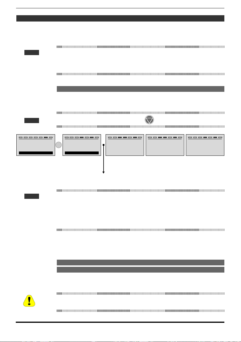
Step 3 - Autotune of the motor
The drive carries out the motor autotune procedure (real measurement of motor
parameters).
Autotune may last a few minutes.
Note ! If this operation generates an error message (example Error code 1), check the connections of the
power and control circuits (see Step 1 - Connections), check motor data settings (see Step 2 – Motor
data setting) and then repeat the Autotune procedure (or, alternatively, select a different type of procedure (Rotation or Still)
Step 3A - Self-tuning with rotating motor (Autotune rotation)
Use this procedure when the motor is not coupled or the transmission does not
represent more than 5% of the load. This procedure obtains the most accurate
data.
Note ! Autotuning can be cancelled at any time by pressing
T+ T- EN LOC ILim n:0 AL
STARTUP WIZARD
Run autotune rot ?
E=Yes Down=Next
T+ T- EN LOC ILim n:0 AL
STARTUP WIZARD
E
Close Enable input
Esc=Abort
Connect terminal 7 (Enable) to terminal C3 (+24Vdc).
To interrupt this operation, press the ESC key.
T+ T- EN LOC ILim n:0 AL
S E Q . 0 1
Autotune rotation
Press E to execute
PA R : 2 0 2 2
T+ T- EN LOC ILim n:0 AL
Autotune
Progress 5%
Press Esc to abort
T+ T- EN LOC ILim n:0 AL
STARTUP WIZARD
Open Enable input
Note ! At the end of the self-tuning procedure there is a request to open the Enable contact (terminals
7 – S3); the Take tune parameters command (menu 16 MOTOR DATA, PAR: 2078) is automatically
executed.
The calculated parameters are saved in a RAM memory to enable the drive to perform the neces-
sary calculations. These data are lost if the device is switched off. To save the motor data follow the
procedure described in Step 6.
When the Enable contact is opened the drive proposes Step 4 to proceed with the wizard.
Step 3B - Self-tuning with motor at stand-still or coupled to the load
(Autotune still)
Use this procedure when the motor is coupled to a mechanical transmission
and cannot be made to rotate freely.
May cause limited rotation of the shaft.
Peut entraîner une rotation de l’arbre limitée.
Caution
90 ADV200 • Quick start up guide - Specification and installation
Page 91

Note ! Autotuning can be cancelled at any time by pressing
T+ T- EN LOC ILim n:0 AL
STARTUP WIZARD
Run autotune still ?
E=Yes Down=Next
T+ T- EN LOC ILim n:0 AL
STARTUP WIZARD
E
Close Enable input
Esc=Abort
T+ T- EN LOC ILim n:0 AL
S E Q . 0 1
Autotune still
Press E to execute
PA R : 2 0 2 4
T+ T- EN LOC ILim n:0 AL
Autotune
Progress 5%
Press Esc to abort
T+ T- EN LOC ILim n:0 AL
STARTUP WIZARD
Open Enable input
Connect terminal 7 (Enable) to terminal C3 (+24Vdc)
Note ! At the end of the self-tuning procedure there is a request to open the Enable contact (terminals
7 – S3); the Take tune parameters command (menu 16 MOTOR DATA, PAR: 2078) is automatically
executed.
The calculated parameters are saved in a RAM memory to enable the drive to perform the neces-
sary calculations. These data are lost if the device is switched off. To save the motor data follow the
procedure described in Step 6.
When the Enable contact is opened the drive proposes Step 4 to proceed with the wizard.
Step 4 - Setting encoder parameters
For Flux vector CL mode only (Menu 04 DRIVE CONFIG, parameter 04.2 Regulation mode, PAR: 552, default=Flux vector CL).
Note ! Optional card EXP-SESC-I1R1F2-ADL must be installed.
T+ T- EN LOC ILim n:0 AL
03 STARTUP WIZARD
Set encoder param?
E=Yes Down=Next
T+ T- EN LOC ILim n:0 AL
S E Q . 0 1
E
Encoder resolution
Def: 2048
T+ T- EN LOC ILim n:0 AL
S E Q . 0 2
Encoder supply
Def: 5.2
PA R : 2 1 0 0
2048 ppr
PA R : 2 1 0 2
5.2 V
T+ T- EN LOC ILim n:0 AL
S E Q . 0 1
E
Encoder resolution
00 00 0 20 48 ppr
Def: 2048
T+ T- EN LOC ILim n:0 AL
S E Q . 0 2
E
Encoder supply
00 00 0 05 .2 V
Def: 5.2
PA R : 2 1 0 0
PA R : 2 1 0 2
T+ T- EN LOC ILim n:0 AL
E
S E Q . 0 1
Full scale speed
00 00 0 20 48
Def: 2048
T+ T- EN LOC ILim n:0 AL
E
S E Q . 02
Encoder supply
00 00 0 05 .2
Def: 5.2
PA R : 2 1 0 0
ppr
PA R : 2 1 0 2
V
An incorrect encoder voltage setting could result in permanent damage to the device. Check the value
Caution
ADV200 • Quick start up guide - Specification and installation 91
on the encoder data plate.
Page 92

Step 5 - Encoder phasing
For Flux vector CL mode only (Menu 04 DRIVE CONFIG, parameter 04.2 Regulation mode, PAR: 552, default=Flux vector CL).
The drives have a command to start automatic phasing of the absolute encoder
(the brake must be blocked).
Phasing must be repeated whenever:
- the drive is replaced (alternatively, download parameters taken from previous
drive)
- the motor is replaced
- the encoder is replaced.
Note ! For further information see parameters 15.15 PAR 2190 Autophase rotation and 15.16 PAR 2192
Autophase still in the Description of functions and list of parameters manual).
See section A.3.2 Phasing in the Appendix for further information.
T+ T- EN LOC ILim n:0 AL
03 STARTUP WIZARD
Run phasing still ?
E=Yes Down=Next
(1) (2) (3) (4)
T+ T- EN LOC ILim n:0 AL
Autotune
Progress 100 %
Open Enable input
(5)
T+ T- EN LOC ILim n:0 AL
S E Q . 0 1
E
Autotune still
Press E to execute
T+ T- EN LOC ILim n:0 AL
Autotune
Done
PA R : 2 0 2 4
T+ T- EN LOC ILim n:0 AL
Autotune
E
Progress 0 %
Close Enable input
T+ T- EN LOC ILim n:0 AL
Autotune
Progress 10 %
Press ESC to abort
Step 6 - Setting the maximum speed reference value (Set max speed)
This step is used to dene the maximum motor speed value that can be reached
with each single reference signal (analog or digital).
T+ T- EN LOC ILim n:0 AL
STARTUP WIZARD
Set max speed ?
E=Yes Down=Next
T+ T- EN LOC ILim n:0 AL
S E Q . 0 1
E
Full scale speed
Def: +1500
PA R : 6 8 0
+1500 rpm
T+ T- EN LOC ILim n:0 AL
S E Q . 0 1
E
Full scale speed
+0 0 00 0 15 00 rpm
Def: +1500
PA R : 6 8 0
T+ T- EN LOC ILim n:0 AL
E
S E Q . 0 1
Full scale speed
00 00 0 07 50
+ rpm
Def: +1500
PA R : 6 8 0
After setting the speed, proceed to Step 5 to set the acceleration and deceleration
ramp parameters.
92 ADV200 • Quick start up guide - Specification and installation
Page 93

Step 7 - Setting ramp parameters (Set ramps)
Set the acceleration and deceleration times for the prole of ramp 0 :
Frequency
T
T+ T- EN LOC ILim n:0 AL
S E Q . 0 2
PA R : 70 2
Deceleration time 0
+10.00 s
Def: +10.00
T+ T- EN LOC ILim n:0 AL
STARTUP WIZARD
Set ramps ?
E=Yes Down=Next
PAR: 700 PAR: 700
T+ T- EN LOC ILim n:0 AL
S E Q . 0 1
E
Acceleration time 0
PA R : 70 0
+10.00 s
Def: +10.00
Note ! After setting the acceleration and deceleration ramps, the parameters that have been set manually and
calculated using the self-tuning procedures can be saved permanently in a non-volatile flash memory.
To save the parameters proceed to Step 8.
Step 8 - Saving parameters (Save parameters)
To save the new parameter settings, so that they are maintained also after poweroff, proceed as follows:
T+ T- EN LOC ILim n:0 AL
STARTUP WIZARD
Save parameters ?
E=Yes Down=Next
T+ T- EN LOC ILim n:0 AL
S E Q . 0 1
E
Save parameters
Press E to execute
PA R : 55 0
T+ T- EN LOC ILim n:0 AL
S E Q . 0 1
E
Save parameters
In progress
PA R : 55 0
T+ T- EN LOC ILim n:0 AL
S E Q . 0 1
Save parameters
Done
PA R : 55 0
T+ T- EN LOC ILim n:0 AL
STARTUP WIZARD
End of sequence !
Up=Back Down=Exit
ADV200 • Quick start up guide - Specification and installation 93
Page 94

Step 9 – Setting the synchronous motor in “Flux Vect OL” mode
(sensorless) for a typically variable torque-type load with OL control
Menu 04 CONFIG DRIVE, parameter 04.2 Regulation mode, PAR: 552, set = [1]
Flux vector OL .
Test with no load applied to the motor
1. Close the Enable contact (terminals S3 – 7)
2. Close the FR forward src contact (PAR 1042), terminals S3 – 8. The drive
starts magnetising the motor.
3. Using the potentiometer, gradually increase the reference signal until reaching
the maximum speed.
4. Open the FR forward src contact (PAR 1042), terminals S3 – 8, until reaching
the minimum set speed requested by the application.
5. Check that the ramp is linear and, once the set value has been reached, that
the speed remains stable.
Test with rated load applied to the motor
1. Close the Enable contact (terminals S3 – 7)
2. Close the FR forward src contact (PAR 1042), terminals S3 – 8. The drive
starts magnetising the motor.
3. Using the potentiometer, gradually increase the reference signal until reaching
the maximum speed.
4. Open the FR forward src contact (PAR 1042), terminals S3 – 8, until reaching
the minimum set speed requested by the application.
If the motor with the load applied has difculty starting:
increase the value of SLS id current corr (PAR 7014) (this value depends on the
size of the drive) in steps of 10% until the problem is eliminated.
T+ T- EN LOC ILim n:0 AL
18 SPEED REG GAINS
19 REGULATOR PARAM
20 TORQUE CONFIG
21 SENSORLESS
T+ T- EN LOC ILim n:0 AL
2 1 . 0 4
SLS id current corr
x3
Def: 7.36
PA R : 7 0 1 4
7.36
T+ T- EN LOC ILim n:0 AL
2 1 . 0 4
SLS id current corr
E
A
Def: 7.36
PA R : 7 0 1 4
00 0 0 0 0 7 . 36
A
If mechanical vibrations occur during steady state operation:
reduce the value of SLS id current corr (PAR 7014) (this value depends on the
size of the drive) in steps of 10% so as to reach a compromise with that stated
above, also changing parameter SLS obs speed gain (PAR 7022) in steps of 0.
T+ T- EN LOC ILim n:0 AL
18 SPEED REG GAINS
19 REGULATOR PARAM
20 TORQUE CONFIG
21 SENSORLESS
T+ T- EN LOC ILim n:0 AL
2 1 . 0 8
SLS obs speed gain
...
Def: 1.000
PA R : 7 0 2 2
1.000
If current overloads occur during steady state operation:
with the drive disabled and the Enable contact (terminals S3 – 7) open, change
parameter SLS id sel ctrl (PAR 7020) by selecting control “[1] Advanced”.
94 ADV200 • Quick start up guide - Specification and installation
T+ T- EN LOC ILim n:0 AL
2 1 . 0 8
SLS obs speed gain
E
00 0 0 1 . 0 0 0
Def: 1.000
PA R : 7 0 2 2
Page 95

T+ T- EN LOC ILim n:0 AL
18 SPEED REG GAINS
19 REGULATOR PARAM
20 TORQUE CONFIG
21 SENSORLESS
T+ T- EN LOC ILim n:0 AL
2 1 . 0 7
SLS id sel ctrl
Normal
...
Value 0
PA R : 7 0 2 0
E
T+ T- EN LOC ILim n:0 AL
2 1 . 0 7
SLS id sel ctrl
Value 1
PA R : 7 0 2 0
Advanced
If vibrations are present at Start, modify the following parameters:
Enable parameter SLS rotor alignment (PAR 7048) and perform the alignment
procedure as follows:
T+ T- EN LOC ILim n:0 AL
18 SPEED REG GAINS
19 REGULATOR PARAM
20 TORQUE CONFIG
21 SENSORLESS
T+ T- EN LOC ILim n:0 AL
2 1 . 1 9
SLS rotor alignment
Disable
...
Value 0
PA R : 7 0 4 8
E
T+ T- EN LOC ILim n:0 AL
2 1 . 1 9
SLS rotor alignment
Value 1
PA R : 7 0 4 8
Enable
1. Close the Enable contact (terminals S3 – 7)
2. Set Speed reference = 0
3. Close the FR forward src contact (PAR 1042), terminals S3 – 8.
4. Wait 1 second (value set in parameter PAR 7050), gradually increase the
reference signal using the potentiometer, until exceeding 10% of the maximum
speed
5. Using the potentiometer again, reduce the speed reference signal to zero.
6. Open the FR forward src contact (PAR 1042), terminals S3 – 8.
If the vibrations have not been entirely eliminated, increase the value of parameter
SLS max speed OL (PAR 7012) in steps of 10% until reaching the best working
condition.
T+ T- EN LOC ILim n:0 AL
18 SPEED REG GAINS
19 REGULATOR PARAM
20 TORQUE CONFIG
21 SENSORLESS
T+ T- EN LOC ILim n:0 AL
2 1 . 0 3
SLS max speed OL
x2
Def: 120
PA R : 7 0 1 2
120
T+ T- EN LOC ILim n:0 AL
2 1 . 0 3
SLS max speed OL
E
rpm
Def: 120
PA R : 7 0 1 2
00 0 0 0 0 1 2 0
rpm
To save the new parameter settings, so that they are maintained also after poweroff, proceed as follows:
T+ T- EN LOC ILim n:0 AL
01 MONITOR
02 DRIVE INFO
03 STARTUP WIZARD
04 DRIVE CONFIG
ADV200 • Quick start up guide - Specification and installation 95
T+ T- EN LOC ILim n:0 AL
0 4 . 0 1
Save arameters
PA R : 5 5 0
p
Press E to execute
T+ T- EN LOC ILim n:0 AL
0 4 . 0 1
p
Save arameters
E
gp
In ro ress
PA R : 5 5 0
T+ T- EN LOC ILim n:0 AL
0 4 . 0 1
Save arameters
PA R : 5 5 0
p
Done
Page 96

7.2 First customized start-up
In this section a startup test is performed, using a standard conguration, to check
drive functioning and command connections.
A programming sequence has to be run to achieve a rst simple customisation in
order to be able to set the drive for the requested application.
Note ! The main sections to be used, depending on the desired conguration, are
described below.
• Typical connection diagrams
Auxiliary control circuits �������������������������������� see chapter 5.6, gure 5.6.1
Typical connection diagram, connection through terminals strip ��� see chapter 5.6, gure 5.6.2
Potentials of the control section, Digital I/O PNP connection ������ see chapter 5.2.4, gure 5.2.4.1
Other inputs connections (NPN-PNP) ����������������������� see chapter 5.2.4, gure 5.2.4.2
NPN outputs connection �������������������������������� see chapter 5.2.4, gure 5.2.4.3
• Digital inputs
The table on chapter 5.2.3 shows the default settings for the analog and digital
inputs and outputs.
Note ! Digital input settings can only be edited from the Expert parameters, see paragraph “6.5.2 Selection of
Easy / Export mode”, page 61.
7.2.1 For Asynchronous Motors
• Selecting the regulation mode
First set the regulation mode in the Regulation mode parameter (04 DRIVE CONFIG menu, PAR: 552) :
0 V/f control. This is the simplest and least advanced control mode. This mode
can also be used to control several motors connected in parallel using a single
drive.
1 Open loop eld-oriented vector control (Flux vector OL). In this mode,
once the motor parameter self-tuning procedure has been performed, it is
possible to create a mathematical model on which to perform all the necessary calculations in order to obtain high performance levels, especially high
motor torque levels, even at very low speeds without the use of feedback, and
achieve signicant dynamic performance.
2 Closed loop eld-oriented vector control (Flux vector CL). This mode can
be used to obtain maximum drive-motor efciency in terms of speed precision,
dynamic system response and motor torque regulation. It requires feedback
by a digital encoder keyed to the motor shaft and connected to the relative
optional expansion card mounted in the drive.
96 ADV200 • Quick start up guide - Specification and installation
Page 97

• Selecting the type of reference
After setting the regulation mode, the source of the speed reference must be set in
the Ramp ref 1 src parameter (05 REFERENCES menu, PAR: 610). This source
can be selected from among those listed in the L_MLTREF selection list:
1 Analog input 1 mon parameter (PAR: 1500) to use the signal applied to
terminals 1 – 2 of analog input 1 (14 - ANALOG INPUTS menu).
2 Dig ramp ref 1 parameter (05 - REFERENCES menu, PAR: 600) to set a
digital speed inside the drive.
3 Multi ref out mon parameter (07 - MULTI REFERENCE menu, PAR: 852) to
select the digital speeds using the digital inputs of the drive.
4 Mpot output mon parameter (08 - MOTOPOTENTIOMETER menu, PAR:
894) to use the internal motor potentiometer of the drive. If sending the command from the operator keypad, to use the motor potentiometer function enter
the Mpot setpoint parameter (PAR: 870) modify mode and press the Up (▲)
and Down (▼) keys.
5 Jog output mon parameter (09 - JOG FUNCTION menu, PAR: 920) to use
one of the drive’s internal jog speeds.
Signals from expansion cards, the serial line or eldbus can also be set as speed
references (see the detailed description of parameters).
• Setting the type of analog reference
If the analog input has been selected, choose the type of signal to use in the Analog inp 1 type parameter (14 - ANALOG INPUTS menu, PAR.1502):
0 ± 10V
1 0-20mA o 0-10V
2 4-20mA
As well as programming the Analog inp 1 type parameter (PAR:1502) you must
also verify the position of the switches on the regulation card, as showed on
chapter 5.2.4.
• Ramps setting
The acceleration and deceleration ramps can be set in Acceleration time 0 (06 RAMPS menu, PAR: 700) and Deceleration time 0 (PAR: 702).
The signal available on the analog input can be adjusted using Analog inp 1
scale parameter (14 - ANALOG INPUTS menu, PAR: 1504), An inp 1 offset
tune parameter (PAR: 1506) and An inp 1 gain tune parameter (PAR: 1508).
To use a digital speed to control the drive, enter it in the Dig ramp ref 1 parameter
(05 - REFERENCES menu, PAR: 600).
The ramps are the same used with the reference signal from the analog input.
• Multispeed
To use more than one digital speed, use the multi-speed function.
First select the source of the speed signals Multi ref 0 src and Multi ref 1 src (07
- MULTI REFERENCE menu, PAR: 832 e 834) from the L_MLTREF selection list.
Next dene which digital inputs are to perform switching between the various
speeds; use the Multi ref sel .. src parameters (PAR: from 840 to 846) to select
the signals to use from the L_DIGSEL2 selection list. Set the desired speeds in
the Multi reference 0...7 parameters (PAR: from 800 to 814).
ADV200 • Quick start up guide - Specification and installation 97
Page 98

Also in this case the ramps can be set in the Acceleration time 0 parameter
(06 - RAMPS menu, PAR: 700) and Deceleration time 0 parameter (PAR: 702)
parameters.
• Motor potentiometer
To use the motor potentiometer, the signals to increase or decrease the reference
must be dened: set the Mpot up src parameter (08 - MOTOPOTENTIOMETER
menu, PAR: 884) and Mpot down src parameter (PAR: 886) parameters respectively to increase and decrease the reference using selection list L_DIGSEL2.
Set the motor potentiometer ramps using Mpot acceleration (PAR: 872) and
Mpot deceleration parameters (PAR: 874).
• Jog
Finally, for Jog mode, select the control terminal in the Jog cmd + src parameter
(09 - JOG FUNCTION menu, PAR: 916), using a signal from selection list L_DIGSEL2.
The Jog speed must be written in the Jog setpoint parameter (PAR: 910), while
the acceleration and deceleration ramps can be set, respectively, in Jog accelera-
tion (PAR: 912) and Jog deceleration parameters (PAR: 914).
• Speed limits
After selecting the reference, set the speed limits in the following parameters (05 REFERENCES menu):
- Full scale speed (PAR: 680). Setting of the maximum motor speed, which
usually coincides with the rated speed indicated on the motor data plate.
- Speed ref top lim (PAR: 670). Upper speed limit: the maximum setting is
200% of the Full scale speed.
- Speed ref bottom lim (PAR: 672). Lower speed limit: the maximum setting is
-200% of the Full scale speed.
- Overspeed threshold (24 - ALARM CONFIG menu, PAR: 4540). Overspeed
alarm limit.
• Input and Output terminals
The default setting of the input terminals is as follows:
- Terminal 7 Digital input E Enable
- Terminal 8 Digital input 1 FR forward src, PAR 1042
- Terminal 9 Digital input 2 FR reverse src, PAR 1044
- Terminal 10 Digital input 3 Multi ref sel 0 src
- Terminal 11 Digital input 4 Multi ref sel 1 src
- Terminal 12 Digital input 5 Fault reset src
- Terminal S3 + 24V OUT I/O supply
The default conguration of the terminals dedicated to digital outputs are as follows:
- Terminal R14 Digital output 1 Drive OK (Relay 1)
- Terminal R11 COM Digital output 1 Common digital output 1 (Relay 1)
- Terminal R24 Digital output 2 Drive ready (Relay 2)
- Terminal R21 COM Digital output 2 Common digital output 2 (Relay 2)
- Terminal 13 Digital output 3 Speed is 0 delay
- Terminal IC1 COM Digital output 3/4 Common ref. for digital outputs 3 / 4
- Terminal 14 Digital output 4 Ref is 0 delay
- Terminal IS1 PS Digital output 3/4 Digital outputs 3 / 4 power supply
98 ADV200 • Quick start up guide - Specification and installation
Page 99

Signals for the digital outputs can be programmed using the Digital output 1...4
src parameters (13 - DIGITAL OUTPUTS menu, PAR: from 1310 to 1316) using
the settings in the L_DIGSEL1 selection list.
The drive also includes two analog outputs which are not factory-set. These
outputs must be enabled by setting Analog out 1 src (15 - ANALOG OUTPUTS
menu, PAR: 1800) and Analog out 2 src parameters (PAR: 1802) with a signal
selected from selection list L_ANOUT.
The signal available on analog output 1 is ± 10V, while the analog output 2 signal
can be selected using the Analog out 2 type parameter (PAR: 1848) between:
0 0-20mA
1 4-20mA
2 ± 10V
The analog output signal can be adjusted using Analog out 1 scale (PAR: 1808)
and Analog out 2 scale parameters (PAR:1810).
• Keypad
Use the LOC / REM key with the Enable input open (terminal 7 on terminal strip
T2) to control running, to stop and reverse the direction of rotation of the motor
using the operator keypad on the drive. Use the potentiometer or an analog signal
to control speed.
For information on how to use a digital speed reference, see the example on paragraph “7.3.3 Variable interconnections mode”, page 104. The reference can have a positive or
negative value, making it possible to reverse the direction of rotation of the motor.
When the Enable input is closed, to enable motor running press START. The mo-
tor starts the acceleration ramp and moves to the speed set in the FWD direction.
With the motor running you can adjust the speed using the Dig ramp ref 1 parameter (PAR: 600) and the acceleration/deceleration ramps using Acceleration time
0 (PAR: 700) and Deceleration time 0 (PAR: 702).
To change the direction of rotation press FWD/REV.
To stop the motor with the deceleration ramp, press STOP.
If the Enable contact is opened the inverter bridge is immediately disabled and the
motor stops for inertia
To return to control using the terminal strip commands and analog speed reference:
1. Stop the motor
2. Open the Enable terminal
3. Press LOC / REM key.
Note ! For more customizations and any information that is not included in this initial customization guide, see
the description of the parameters in this manual.
ADV200 • Quick start up guide - Specification and installation 99
Page 100

7.2.2 For Synchronous Motors, Flux vector CL and Flux vector OL control
Note ! At start-up, the synchronous motor may turn slightly in the direction opposite to that of rotation. This
may depend on the parameter settings, the position of the rotor and the inertia/load applied.
• Selecting the regulation mode
First set the regulation mode in the Regulation mode parameter (04 DRIVE CONFIG menu, PAR: 552) :
1 Open-loop eld-oriented vector control (sensorless).
(Flux vector OL) In this mode, once the motor parameter self-tuning procedure
has been performed, it is possible to create a mathematical model on which to
perform all the necessary calculations in order to obtain high performance levels,
especially high motor torque levels, even at very low speeds without the use of
feedback, and achieve high dynamic performance increasingly similar to closedloop operation.
2 Closed loop eld-oriented vector control.
(Flux vector CL) This mode can be used to obtain maximum drive-motor ef-
ciency in terms of speed precision, dynamic system response and motor torque
regulation. It requires feedback by a digital encoder keyed to the motor shaft
and connected to the relative optional expansion card mounted in the drive.
• Inertia
Set the value of inertia applied to the motor axis in the Inertia parameter (menu 18
- SPEED REG GAINS, PAR: 2240).
• Selecting the type of reference
After setting the regulation mode, the source of the speed reference must be set in
the Ramp ref 1 src parameter (05 REFERENCES menu, PAR: 610). This source
can be selected from among those listed in the L_MLTREF selection list:
1 Analog input 1 mon parameter (PAR: 1500) to use the signal applied to
terminals 1 – 2 of analog input 1 (14 - ANALOG INPUTS menu).
2 Dig ramp ref 1 parameter (05 - REFERENCES menu, PAR: 600) to set a
digital speed inside the drive.
3 Multi ref out mon parameter (07 - MULTI REFERENCE menu, PAR: 852) to
select the digital speeds using the digital inputs of the drive.
4 Mpot output mon parameter (08 - MOTOPOTENTIOMETER menu, PAR:
894) to use the internal motor potentiometer of the drive. If sending the command from the operator keypad, to use the motor potentiometer function enter
the Mpot setpoint parameter (PAR: 870) modify mode and press the Up (▲)
and Down (▼) keys.
5 Jog output mon parameter (09 - JOG FUNCTION menu, PAR: 920) to use
one of the drive’s internal jog speeds.
Signals from expansion cards, the serial line or eldbus can also be set as speed
references (see the detailed description of parameters).
• Setting the type of analog reference
If the analog input has been selected, choose the type of signal to use in the Ana-
100 ADV200 • Quick start up guide - Specification and installation
 Loading...