

Page 1
...... Instruction manual
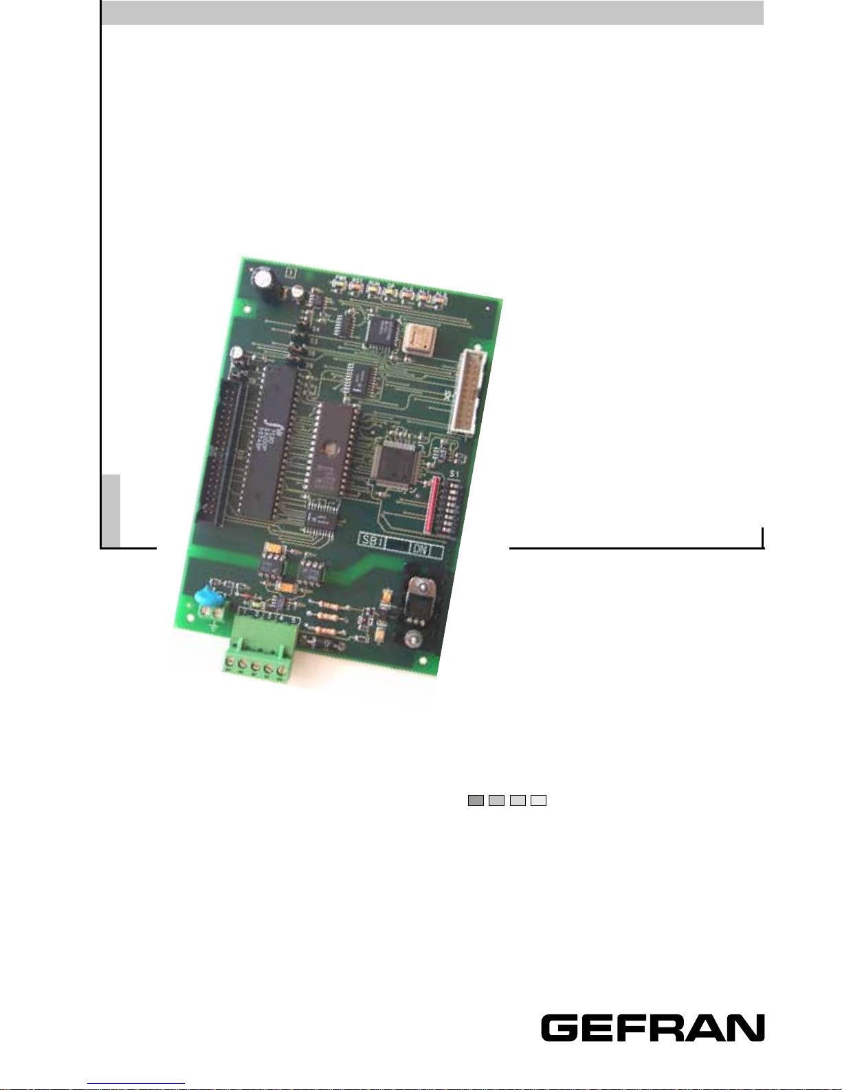
Field bus interface card
SBI-DN
Interface Board
DeviceNet
Industrial Application
Page 2

The information held in this manual can be modied without notice and it is
not strictly binding for GEFRAN S.p.A.
For no reason no part of this manual can be reproduced in any form or by
any means (including recording and photocopying) without a written consent
of GEFRAN S.p.A.
Before the inverter installation, wiring, commissioning and inspection, read
carefully this instruction manual.
Keep the manual in a safe place and at everyone’s disposal during the drive
functioning period.
GEFRAN S.p.A. is not responsible for those mistakes that may be found in
this manual and for the damages that they may arouse.
All rights reserved.
Page 3

SBI-DN
3
—————— Interface Board DeviceNet ——————
TABLE OF CONTENTS
1.0 INTRODUCTION .............................................................................. 7
1.1 THE MANUAL ..................................................................................... 7
1.2 DEVICENET GENERAL DESCRIPTION ....................................................7
2.0 HARDWARE DESCRIPTION ...........................................................9
2.1 DIMENSIONS, WEIGHT, PROTECTION DEGREE .....................................9
2.2 INSTALLATION ...................................................................................10
2.3 POWER SUPPLY ................................................................................. 12
2.4 CONNECTORS .................................................................................... 13
2.5 DIP SWITCHES ................................................................................... 13
2.6 LEDS .................................................................................................. 14
2.7 TECHNICAL SPECIFICATIONS ............................................................. 14
2.8 INTERFACE ........................................................................................14
3.0 DEVICENET FUNCTION .................................................................15
3.1 OBJECT DESCRIPTION ...................................................................... 15
3.1.1 Object Model ......................................................................................... 15
3.1.2 How Objects Affect Behavior. .................................................................. 17
3.1.3 Dening Object Interface ........................................................................ 17
3.1.4 I/O Assembly Instances .......................................................................... 17
3.1.5 I/O Assembly Data Attributes Format ......................................................18
3.2 DATA TRANSFER VIA EXPLICIT MESSAGING ...................................... 18
3.2.1 Drive Parameter Access ......................................................................... 18
3.2.1.1 Class code ..................................................................................................... 19
3.2.1.2 Class attributes .............................................................................................. 19
3.2.1.3 Instance Attributes ......................................................................................... 19
3.2.1.4 Common Services .......................................................................................... 19
3.2.1.5 Object Specic services ................................................................................. 19
3.2.1.6 Behavior ......................................................................................................... 19
3.2.1.6.1 Write Drive Parameter ................................................................................. 19
3.2.1.6.1.1 Write Drive Parameter Request ................................................................. 19
3.2.1.6.1.2 Write drive parameter - Reply OK ............................................................. 20
3.2.1.6.1.3 Write drive parameter - Reply Error .......................................................... 20
3.2.1.6.2 Read Drive Parameter .................................................................................. 21
3.2.1.6.2.1 Read Drive Parameter Request ................................................................. 21
3.2.1.6.2.2 Read drive parameter - Reply OK .............................................................. 21
3.2.1.6.2.3 Read drive parameter - Reply Error ........................................................... 21
3.2.2 APC Option Parameter Access ........................................................................... 22
3.2.2.1 Class code ..................................................................................................... 22
3.2.2.2 Class attributes .............................................................................................. 22
3.2.2.3 Instance Attributes ......................................................................................... 22
3.2.2.4 Common Services .......................................................................................... 22
3.2.2.5 Object Specic services ................................................................................. 23
3.2.2.6 Behavior ......................................................................................................... 23
Page 4

GEFRAN
—————— Interface Board DeviceNet ——————
4
3.2.2.6.1 Write APC Parameter ................................................................................... 23
3.2.2.6.1.1 Write APC Parameter Request .................................................................. 23
3.2.2.6.1.2 Write APC parameter - Reply OK .............................................................. 24
3.2.2.6.1.3 Write APC parameter - Reply Error ........................................................... 24
3.2.1.6.2 Read APC Parameter ................................................................................... 24
3.2.1.6.2.1 Read APC Parameter Request .................................................................. 24
3.2.1.6.2.2 Read APC parameter - Reply OK ............................................................... 25
3.2.1.6.2.3 Read APC parameter - Reply Error ............................................................ 25
4.0 POLLING FUNCTION .....................................................................26
4.1 SETTING OF POLLING PARAMETERS.................................................. 26
4.1.1 Conguration object of the Polling parameters S->M .............................26
4.1.1.1 Class code ..................................................................................................... 27
4.1.2 Class attributes ...................................................................................... 27
4.1.3 Istance attributes ................................................................................... 27
4.1.4 Common services .................................................................................. 27
4.1.5 Object Specic services ......................................................................... 28
4.1.6 Behavior................................................................................................. 28
4.1.6.1 Write Polling S->M Conguration .................................................................. 28
4.1.6.1.1 Write Single Polling S->M Conguration ..................................................... 28
4.1.6.1.2 Write Single Polling S->M Conguration - Reply OK ................................... 28
4.1.6.1.3 Write Single Polling S->M Conguration - Reply Error ................................ 29
4.1.6.1.4 Write Entire Polling S->M Conguration ...................................................... 29
4.1.6.1.5 Write Entire Polling S->M Conguration - Reply OK .................................... 30
4.1.6.1.6 Write Entire Polling S->M Conguration - Reply Error ................................. 30
4.1.6.2 Read S->M Polling Conguration ................................................................... 30
4.1.6.2.1 Read Single Polling S->M Conguration ..................................................... 30
4.1.6.2.2 Read Single Polling S->M Conguration - Reply OK .................................... 31
4.1.6.2.3 Read Single Polling S->M Conguration - Reply Error ................................. 31
4.1.6.2.4 Read Entire Polling S->M Conguration ...................................................... 31
4.1.6.2.5 Read Entire Polling S->M Conguration - Reply OK..................................... 31
4.1.6.2.6 Read Entire Polling S->M Conguration - Reply Error ................................. 32
4.2 OBJECT CONFIGURATION POLLING PARAMETERS M->S ..................32
4.2.1 Class code ............................................................................................. 33
4.2.2 Class attributes ...................................................................................... 33
4.2.3 Instance Attributes ................................................................................. 33
4.2.4 Common Services.................................................................................. 33
4.2.5 Object Specic services ......................................................................... 34
4.2.6 Behavior................................................................................................. 34
4.2.6.1 Write Polling M->S Conguration .................................................................. 34
4.2.6.1.1 Write Single Polling M->S Conguration ..................................................... 34
4.2.6.1.2 Write Single Polling M->S Conguration - Reply OK ................................... 34
4.2.6.1.3 Write Single Polling M->S Conguration - Reply Error ................................ 35
4.2.6.1.4 Write Entire Polling M->S Conguration ...................................................... 35
4.2.6.1.5 Write Entire Polling M->S Conguration - Reply OK .................................... 35
4.2.6.1.6 Write Entire Polling M->S Conguration - Reply Error ................................. 36
4.2.6.2 Read M->S Polling Conguration ................................................................... 36
4.2.6.2.1 Read Single Polling M->S Conguration ..................................................... 36
4.2.6.2.2 Read Single Polling M->S Conguration - Reply OK .................................... 36
4.2.6.2.3 Read Single Polling M->S Conguration - Reply Error ................................. 37
Page 5

SBI-DN
5
—————— Interface Board DeviceNet ——————
4.2.6.2.4 Read Entire Polling M->S Conguration ...................................................... 37
4.2.6.2.5 Read Entire Polling M->S Conguration - Reply OK..................................... 37
4.2.6.2.6 Read Entire Polling M->S Conguration - Reply Error ................................. 38
5.0 SETTING OF VIRTUAL DIGITAL I/O ...............................................39
5.1 OBJECT CONFIGURATION VIRTUAL DIGITAL INPUTS .......................... 39
5.1.1 Class code ............................................................................................. 39
5.1.2 Class attributes ...................................................................................... 39
5.1.3 Instance Attributes ................................................................................. 40
5.1.4 Common Services.................................................................................. 40
5.1.5 Object Specic services ......................................................................... 40
5.1.6 Behavior................................................................................................. 40
5.1.6.1 Write Virtual Digital Input Conguration .......................................................... 41
5.1.6.1.1 Write Single Virtual Digital Input Conguration ............................................. 41
5.1.6.1.2 Write Single Virtual Digital Input Conguration - Reply OK ...........................41
5.1.6.1.3 Write Single Virtual Digital Input Conguration - Reply Error ........................41
5.1.6.1.4 Write Entire Virtual Digital Input Conguration.............................................. 42
5.1.6.1.5 Write Entire Virtual Digital Input Conguration - Reply OK ............................ 42
5.1.6.1.6 Write Entire Virtual Digital Input Conguration - Reply Error ......................... 42
5.1.6.2 Read Virtual Digital Input Conguration........................................................... 43
5.1.6.2.1 Read Single Virtual Digital Input Conguration ............................................. 43
5.1.6.2.2 Read Single Virtual Digital Input Conguration - Reply OK ............................43
5.1.6.2.3 Read Single Virtual Digital Input Conguration - Reply Error .........................44
5.1.6.2.4 Read Entire Virtual Digital Input Conguration .............................................. 44
5.1.6.2.5 Read Entire Virtual Digital Input Conguration - Reply OK............................. 44
5.1.6.2.6 Read Entire Virtual Digital Input Conguration - Reply Error .........................45
5.2 CONFIGURATION OBJECT VIRTUAL DIGITAL OUTPUT ........................ 45
5.2.1 Class code ............................................................................................. 45
5.2.2 Class attributes ...................................................................................... 45
5.2.3 Instance Attributes ................................................................................. 46
5.2.4 Common Services.................................................................................. 46
5.2.5 Object Specic services ......................................................................... 46
5.2.6 Behavior................................................................................................. 46
5.2.6.1 Write Virtual Digital Output Conguration ........................................................ 47
5.2.6.1.1 Write Single Virtual Digital Output Conguration .......................................... 47
5.2.6.1.2 Write Single Virtual Digital Output Conguration - Reply OK ......................... 47
5.2.6.1.3 Write Single Virtual Digital Output Conguration - Reply Error ...................... 47
5.2.6.1.4 Write Entire Virtual Digital Output Conguration ........................................... 48
5.2.6.1.5 Write Entire Virtual Digital Output Conguration - Reply OK ..........................48
5.2.6.1.6 Write Entire Virtual Digital Output Conguration - Reply Error .......................48
5.2.6.2 Read Virtual Digital Output Conguration ........................................................ 49
5.2.6.2.1 Read Single Virtual Digital Output Conguration........................................... 49
5.2.6.2.2 Read Single Virtual Digital Output Conguration - Reply OK ......................... 49
5.2.6.2.3 Read Single Virtual Digital Output Conguration - Reply Error ...................... 50
5.2.6.2.4 Read Entire Virtual Digital Output Conguration ........................................... 50
5.2.6.2.5 Read Entire Virtual Digital Output Conguration - Reply OK .......................... 50
5.2.6.2.6 Read Entire Virtual Digital Output Conguration - Reply Error ....................... 51
6.0 FUNCTION ERROR CODES ...........................................................52
7.0 KEYPAD INTERFACE ..................................................................... 54
Page 6

GEFRAN
—————— Interface Board DeviceNet ——————
6
7.1 MAIN MENU STRUCTURE .................................................................. 54
7.1.2 Control of warning and error messages .................................................. 54
7.2 OFFSET MENU ................................................................................... 54
7.2.1 Edit Offset .............................................................................................. 55
7.3 POLLING MENU..................................................................................55
7.3.1 Edit for Drive parameter assignment to the Polling I/O function ............... 56
7.4 VIRTUAL DIGITAL I/O MENU ...............................................................58
7.5 DRIVE VIRTUAL DIGITAL I/O PARAMETER ASSIGNMENT .......................
EDITING..............................................................................................59
7.6 PASSWORD MENU ............................................................................ 60
7.6.1 Password request ..................................................................................60
7.6.2 Edit for the Password setting .................................................................. 61
7.7 SBI INFO MENU .................................................................................. 62
7.7.1 Display node address (MAC ID) .............................................................. 62
7.7.2 Display Baud Rate .................................................................................. 62
7.7.3 Node status............................................................................................ 63
7.7.3.1 DeviceNet ERROR TYPES ................................................................................ 63
7.7.4 Status of allocation................................................................................. 65
7.7.5 CNXN status ........................................................................................... 66
7.7.6 I/O CNXN status ..................................................................................... 66
7.7.7 DUP MAC ID TEST (DMC) ....................................................................... 66
7.7.8 Display Software version (Sotware version) ............................................ 67
7.7.9 Display compatibility index(Compatib. index) .......................................... 67
7.8 EDIT ................................................................................................... 68
8.0 MISCELLANEOUS ......................................................................... 69
8.1 DEFINITIONS ...................................................................................... 69
8.2 REFERENCES ..................................................................................... 69
Page 7

SBI-DN
7
—————— Interface Board DeviceNet ——————
1.0 INTRODUCTION
The manual describes the optional SBI-DN card for connecting of inverters and
converters to DeviceNet networks.
Drives belonging to TPD32-EV series can be connected in network through the
SBI-DN board.
This manual is intended for design engineeres and technicians responsible for the
maintenance, commissioning and operation of DeviceNet systems.
A basic knowledge of DeviceNet is assumed and may be found in the following
manuals:
- DeviceNet Specications. Volume 1 - DeviceNet Communication Model and
Protocol (Issued by ODVA).
- DeviceNet Specications. Volume 2 - DeviceNet Device Proles and Object
Library (Issued by ODVA).
1.1 THE MANUAL
Chapter 2 Dimensions, board mechanical installation, electric
connections and Dipswitch setting.
Chapter 3 DeviceNet functions: description of the objects control-
led by the board, data transfer via “Explicit messaging”.
Chapter 4 “Polling” operations for the exchange of Drive para-
meters between the Master and the interface board
(M->S and S->M)
Chapter 5 Setting of virtual digital I/Os
Chapter 6 Error codes
Chapter 7 Keypad menus
Chapter 8 Denitions and references.
1.2 DEVICENET GENERAL DESCRIPTION
DeviceNet is a prole of communication for industrial systems based on CAN.
As protocol CAN (ISO 11898) is used CAN2.0A with the 11 bit identier.
The SBI board is developed as “Slave UCMM Capable Device” for operating only
in “Predened Master/Slave Connection Set”.
The data transfer is carried out cyclically; the Master unit reads the data supplied
Page 8

GEFRAN
—————— Interface Board DeviceNet ——————
8
by the Slaves and writes the Slave reference data; the Baud Rate supported by
the SBI board are:
- 125 kbit
- 250 kbit
- 500 kbit .
The physical support is given by the RS485 serial line; a maximum of 64 Slaves
can be connected to the Bus.
Page 9
SBI-DN
9
—————— Interface Board DeviceNet ——————
2.0 HARDWARE DESCRIPTION
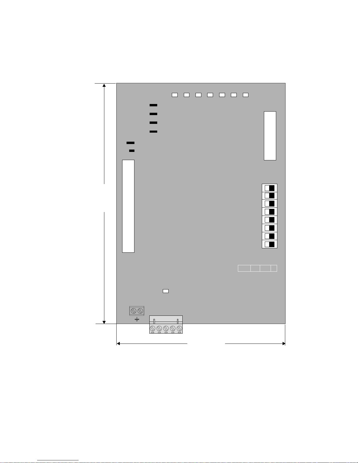
2.1 DIMENSIONS, WEIGHT, PROTECTION DEGREE
SBI DN
12
3
4
5
6
7
8
PWR RST RUN OP AL0 AL1 AL2
XS
X0
S1
ON
OFF
157mm
(6.18")
110mm
(4.33")
H1
S2
S4
S3
S5
S6
S7
S8
BA
BA
BA
BA
BA
1 2345
BUS
Dimensions [mm/in.] 157/6.18” (H) x 110/4.33” (L) x 23/1” (P)
Weight 200 g (7.1 oz)
Protection degree IP00.
Page 10
GEFRAN
—————— Interface Board DeviceNet ——————
10
2.2 INSTALLATION
The SBI interface card is delivered with a kit including 6 standoffs (no.4 L=26.5
mm + no.2 L=10mm), 4 screws, washers the WARRANTY label and a 40-pole at
cable with connectors.
Tools required (depending on models): 7x2 mm slotted-head screwdriver
Torx ® screwdriver: T10, T20, T25.
Cross-head screwdriver #1, 2, 3.
Socket wrench 6mm
® Registered trademark of Camcar LLC of Acument
Global Technologies.
WARNING: Before using the product, read the TPD32-EV safety instruction section
(on TPD32-EV manual). Never open the device or covers while the AC Input power
supply is switched on. Wait for at least one minute before working on the terminals
or inside the device.
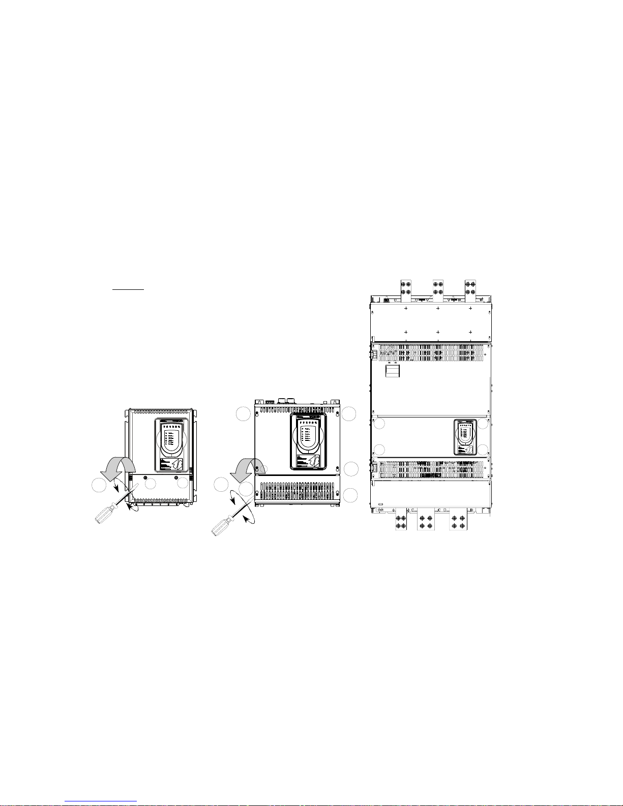
mounting form A mounting form B, C, D
2
3
3
1
1.5 Nm
1
1.5 Nm
2
4
4
4
4
4
4
4
4
Figure 1
1. The front covers of the devices must be removed to mount the option cards. The
devices can be opened without the use of force. Only use the tools specied.
Removing the lower cover:
To remove the lower cover of devices, use a cross screwdriver. Remove the
screws (1) (2), lift cover (3), and open out to the front. See gure 1..
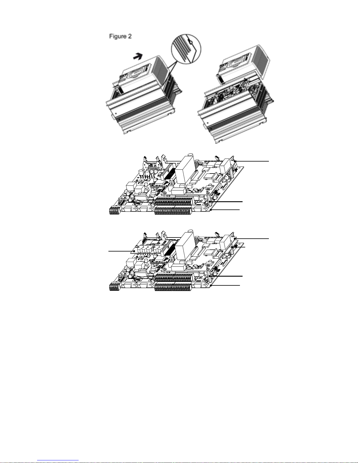
Removing the upper cover:
- Frame A: there are 2 seal pins on the top. To remove the cover, align the two
slots with the pins and lift the cover as shown in Figure 2:
- Frame B-C-D: loosen the 4 screws (4), align the slots of the cover with the
head of the screws and remove the cover. See gure 1.
Disconnect the keypad cable from the control card.
Note: for Frame D, remove only the keypad cover.
Page 11
SBI-DN
11
—————— Interface Board DeviceNet ——————
Figure 3A
R-TPD32-EV
R-TPD32-EV
SBI-DN
SBI-OFM-32
SBI-OFS-32
Distanziali/Stands-off
L=26,5mm (x2)
Distanziali/Stands-off
L=26,5mm (x4)
Distanziali/Stands-off
L=10mm (x2)
SBI-DN
Figure 3B
2. Fasten with screws and no.4 standoffs L=26.5mm the SBI board to the regulation board, see gure 3A. In case there is the SBI-OFM/OFS-32 card, fasten
the SBI card to the drive regulation card by means of screws and 2 standoffs
L=10 mm + 2 standoffs L=26.5mm, see gure 3B.
The BUS connector is turned in the same direction as the regulation board
terminals.
3. The at cable is connected between the XO connector placed on the R-TPD32-
EV card and SBI-DN card. In case there is the APC300 card, connect the at
cable from APC300 to XO connector on SBI-DN card.
4. The Baud Rate of the SBI board is set via the Switches 7 and 8 of the Dipswitch S1. The Baud Rate is detected only when the board is switched on and it
can be modied only by switching off and swtching on the board again.Table
2 shows the relation between the DIP-Switches and the selectable Baud Rate
value. The Default value is 125 Kbaud.
Page 12

GEFRAN
—————— Interface Board DeviceNet ——————
12
Switch 8 Switch 7 Baud Rate
OFF OFF 125 kBaud
OFF ON 250 kBaud
ON OFF 500 kBaud
ON ON 125 KBaud
DN21
5. The dip switch S1 determines the Slave address. The address “0” is reserved
to the Master and it must not be used. The switches S1 -7 and S1-8 do not
determine any address. The address is detected only when the board is switched on. If the address is modied, the Drive has to be switched off and then
switched on in order to assume the new address.
6. Connect the Bus cable to the BUS connection terminal.
7. Switch on the drive.
8. The LEDS PWR and RUN light up.
9. Switch the Device Net power supply on; the LED H1 lights up.
10. The LED OP lights up when the Master/Slave connection has been established.
WARNING: Replace all covers before applying power to the Drive. Failure to
do so may result in death or serious injury.
11. Replace the upper and lower cover by performing the procedures described
in step 1. in the reverse order.
12. To restore the warranty seal, apply the WARRANTY-R label to the TPD32-.EV
converter over the label broken during opening.
Warranty-R label:
2.3 POWER SUPPLY
The power supply is provided by the XO connector, which is used to connect the
data between the SBI board and the Drive regulation board.
Absorbed current: 350 mA
Page 13
SBI-DN
13
—————— Interface Board DeviceNet ——————
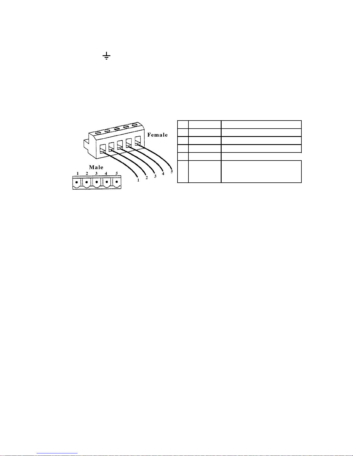
2.4 CONNECTORS
Connector : It allows to connect the ground (GNDE) of the external
power supply to the ground (PE).
Connector XS It allows to connect the ground (PE) to the DeviceNet
cable shield.
Terminal BUS See the gure below. It allows to connect the SBI board
to the DeviceNet network. The pins are the following:
Pin Signal Description
1 CAN_GND Ground/0V/V2 CAN_L Can_L bus line (dominant low)
3 CAN_SHLD CAN shield
4 CAN_H CAN_H bus line (dominant high)
5 CAN_V+
CAN external positive supply
(dedicated for supply of
transceiver and optocouplers)
dn22
2.5 DIP SWITCHES
S3 Interrupt selection from selector S5 (INT1/INT2) to the microcontroller 8032 or
to the interrupt input of the dual port ram (INTR). Default position is A (interrupt
to the dual port ram).
S4 Synchronisation connection for the reset signal of the SBI board to the con-
nected regulation board. Default position is ON.
S5 It is used to connect the signal INT_OPZ to the signal INT1 (S5.B) or to the
signal INT2 (S5.A). The interface board is standard set as OPTION 1, therefore
INT_OPZ is connected to the signal INT1. (Default position is A).
S6 It is used to connect the signal OUT_OPZ to the signal OUT1 (S6.A) or OUT2
(S6.B). Default position is B.
S7 It is used to connect the signal CEM_OPZ to the signal OPZ1 (S7.B) or to the
signal OPZ2 (S7.A). The SBI board is standard set as OPTION 1, therefore
CEM_OPZ is connected to the signal OPZ1. Default position is B.
S8 Connection of the dual port ram BUSY signal to the signal RDY_EXT. Default
position is ON.
Page 14

GEFRAN
—————— Interface Board DeviceNet ——————
14
2.6 LEDS
PWR +5V power supply.
RST Reset active.
H1 +5V power supply on the RS 485 driver side. It is supplied by
the Bus.
RUN It is on when the microcontroller is operating.
OP It is on when the Master/Slave connection is established.
AL0 It blinks when the “Duplicate MAC ID” test has not been passed.
AL1, AL2 Not used and are always off.
2.7 TECHNICAL SPECIFICATIONS
Storage temperature: -20°... +70°C (-68...+158°F)
Operating temperature: 0°... +55°C (32...+131°F)
Such temperatures are suitable to be used with those of the drive, which they are
connected to.
2.8 INTERFACE
The board has to be installed on the regulation board so that the XO connector of
the SBI board is placed near the XO connector of the regulation board, thus keeping
the DeviceNet connection terminal in a downward position.
As for the mechanical connection use the kit delivered with the board.
As for the electrical connection use the 40-pole at cable included in the kit.
As for the Bus connection use a shielded “twisted pair cable”.
The connection among the single boards is carried out via a shielded cable as
shown in the gure below:
SBI-DN
SBI-DN SBI-DN
PE
Shield
Page 15

SBI-DN
15
—————— Interface Board DeviceNet ——————
3.0 DEVICENET FUNCTION
In this chapter are described the functions of DeviceNet managed by the SBI board.
The main characteristics of the board are:
1. The board operates only as Slave in “Predined Master/Slave Connection Set”.
2. Within the “Predened Master/Slave Connection Set” the board is a “UCMM
Capable Device”.
3. The “Explicit Messaging” is managed.
4. The “Polling” for the fast cyclical data exchange Master/Slave is managed.
5. The detection mechanism of the “Duplicate MAC ID” is implemented.
Regarding the “Explicit Messaging” the fragmentation of the data frame, with a total
of max. 38 byte, is managed.
3.1 OBJECT DESCRIPTION
Hereafter you nd the description of the objects managed by the SBI board.
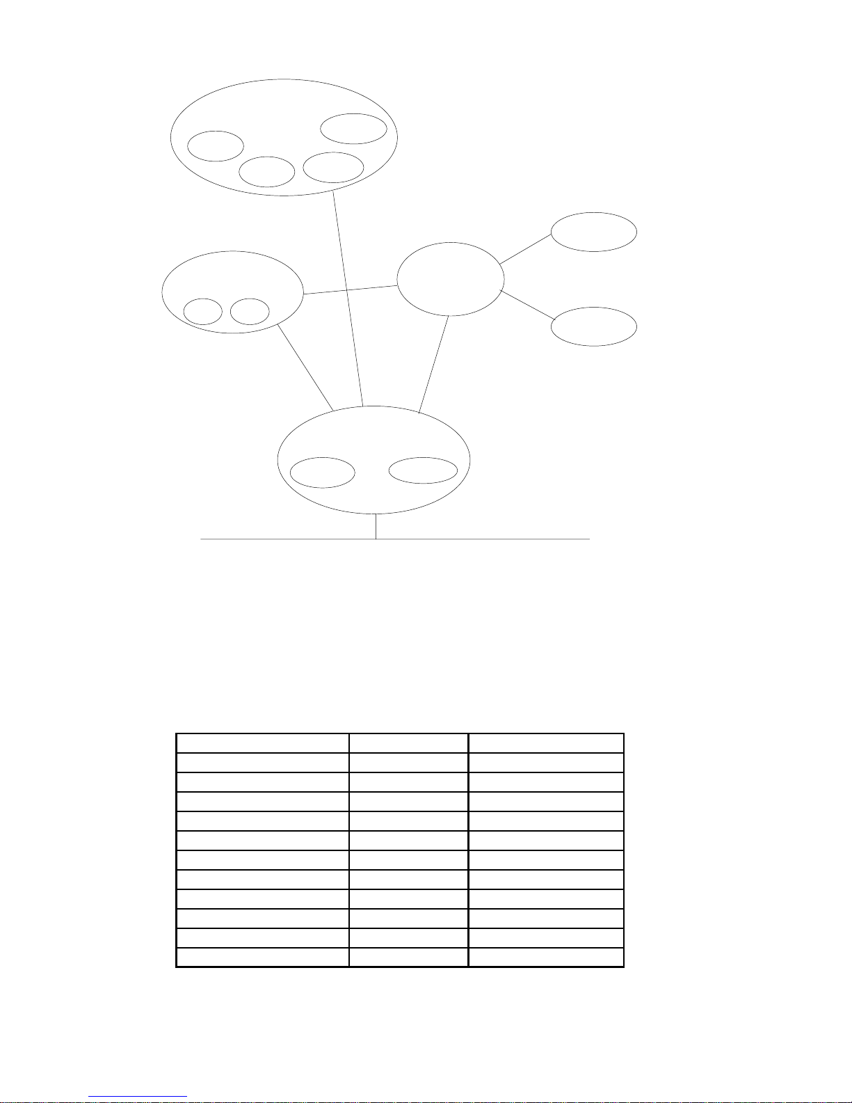
3.1.1 Object Model
The Fig. 3.11 shows the SBI board “Object Model”.
Page 16
GEFRAN
—————— Interface Board DeviceNet ——————
16
Application Objects
DGFC par
PollI/O
Drive par
DgtI/O
Assembly Class
I/OI/O
Message
Router
DeviceNet
IDENTITY
ExplicitI/O
Connection
Figure 3.1: DeviceNet Object Model
The following table shows:
1. The object classes of the SBI-board.
2. If the class is mandatory.
3. The number of instances included in every class.
See “DeviceNet Specications” for the Standard classes.
Object Optional/Required #of Instances
Identity Required 1
Message Router Required 1
DeviceNet Required 1
Connection Required at maximum one Explicit
Assembly Optional 0..2
Drive Parameter Access Optional many
DGFC Parameter Access Optional many
Poll Slave->Master CFG Optional 1
Poll Master->Slave CFG Optional 1
Virtual Digital Input CFG Optional 1
Virtual Digital Output CFG Optional 1
dn310
Page 17

SBI-DN
17
—————— Interface Board DeviceNet ——————
3.1.2 How Objects Affect Behavior.
The “Affect Behaviour” of the objects is reported in the following table:
Object
Effect on Behavior
Identity
Supports “Reset Service”.
Message Router
No effect
DeviceNet
Port attributes configuration
Connection
Conteins the number of logical ports
internal or external to the SBI board
Assembly
Defines the I/O data format
Drive Parameter Access
Drive parameters read/write
DGFCOption Parameter Access
DGFC parameters read/write
Poll Slave->Master CFG
Assignes Drive parameters to the
Polling Slave->Master Word
Poll Master -> Slave CFG
Assignes Drive parameters to the
Polling Master -> Slave Word
Virtual Digital Input CFG
Assignes Drive parameters to the
“Virtual Digital Input ”.
Virtual Digital Output CFG
Assignes Drive parameters to the
“Virtual Digital Output ”.
3.1.3 Defining Object Interface
The object interface of the SBI board is the following:
Object Interface
Identity Message router
Message Router
Explicit Messaging
Connection Instance
DeviceNet Message router
Connection Message router
Assembly
I/O Connection or
Message Router
Drive Parameter Access Message router
DGF Parameter Access Message router
Poll Slave->Master CFG Message router
Poll Master->Slave CFG Message router
Virtual Digital Input CFG Message router
Virtual Digital Output CFG Message router
dn313ge
3.1.4 I/O Assembly Instances
The following table identies the “I/O Assembly” instances of the SBI board:
Number Type Name
195 Input PMSCS Assembly Cons
194 Output PMSCS Assembly Prod
DN325
Page 18

GEFRAN
—————— Interface Board DeviceNet ——————
18
3.1.5 I/O Assembly Data Attributes Format
The “I/O Assembly” attributes format for the Input is the following:
PMSCS Assembly Cons:
Instance Byte Bit 7 Bit 6 Bit 5 Bit 4 Bit 3 Bit 2 Bit 1 Bit 0
0
1
2
….
….
(n2)-1
n*2
….
word #n to consume, low byte
word #n to consume, high byte
195
word #1 to consume, low byte
word #1 to consume, high byte
word #2 to consume, low byte
….
(n) is the number of consumed Words; it is 4 (8bytes).
PMSCS Assembly Prod:
Instance Byte Bit 7 Bit 6 Bit 5 Bit 4 Bit 3 Bit 2 Bit 1 Bit 0
0
1
2
….
….
(n2)-1
n*2
….
word #n to produce, low byte
word #n to produce, high byte
194
word #1 to produce, low byte
word #1 to produce, high byte
word #2 to produce, low byte
….
(n) is the number of produced Words; it is 4 (8bytes).
3.2 DATA TRANSFER VIA EXPLICIT MESSAGING
The data transfer via Explicit Messaging is made through two new objects: one for
accessing the Drive parameters, the other to access the parameters of the APC
option card.
3.2.1 Drive Parameter Access
For reading/writing the drive parameters the Drive Parameter Access object is
dened with the following characteristics:
- Class ID: 66h.
- Class Attribute: Revision
- Instance Attribute: This instance does not provide any attribute.
Page 19

SBI-DN
19
—————— Interface Board DeviceNet ——————
3.2.1.1 Class code
Class Code: 66hex
3.2.1.2 Class attributes
Number
Need in
implementation
Access Rule Name
DeviceNet
Data Type
Description
of Attribute
Semantics of
values
1 Optional Get Revision UINT
Revision of
this object
3.2.1.3 Instance Attributes
Number
Need in
implementation
Access Rule Name
DeviceNet
Data Type
Description
of Attribute
Semantics of
values
This instance does not provide attributes
3.2.1.4 Common Services
This object has no common services.
3.2.1.5 Object Specific services
Class Instance
32
hex
n/a Required Get_Drive_Value Read drive parameter value
33
hex
n/a Required Set_Drive_Value Writes drive parameter value
dn355
Service
Code
Need in
implementation
Service Name Description of Service
3.2.1.6 Behavior
This object is the interface between the DeviceNet network and all Drive parameters. The access to the Drive parameter is carried out by the parameter index; if the
parameter does not exist or may not be accessed for any reason (for example: try
to write a read only parameter) an error code will be returned.
Drive parameters in text format cannot be accessed.
In the following are repeted patterns of how the data frame of data has to be composed for reading/writing Drive parameters.
3.2.1.6.1 Write Drive Parameter
In this example the writing of a Drive parameter is shown; the cases of positive or
wrong writing are distinguished.
3.2.1.6.1.1 Write Drive Parameter Request
The data frame for writing a drive parameter is composed as follows:
Page 20

GEFRAN
—————— Interface Board DeviceNet ——————
20
DATA TYPE FIELD VALUE MEANING
Byte
Service
Code
33hex
SetDrive Parameter -
Object Specific Service.
Class ID 66hex
Drive ParameterAccess
Class Object.
Instance
ID
XXXX
Drive ParameterIndexin
format Lowbyte-High
byte.
XX
Lowbyte-Low worddrive
parameter value.
XX
High byte-Low worddrive
parameter value.
XX
Lowbyte-High worddrive
parameter value.
XX
High byte-High word
drive parameter value.
dn360
VALUE
Byte
2)
See Note
1)
1)
Byte or Word depending on the type of allocation executed by the Master.
2)
The number of bytes of the “Value”-eld depends on the length of the Drive
parameter; i.e.: if the Drive parameter type is “Integer” the length of VALUE is
2 bytes.
3.2.1.6.1.2 Write drive parameter - Reply OK
If the Drive parameter is written correctly, the response is:
DATA TYPE FIELD VA LUE MEANING
Byte Service Code 33hex OR 80hex
Set Drive Parameter
Reply code- Object
Specific Service.
Word Result 0000
Result field equal to zero
means writing correctly
executed.
dn365
3.2.1.6.1.3 Write drive parameter - Reply Error
If the writing of the drive parameter has been rejected, the response is the following:
DATA TYPE FIELD VA LUE MEANING
Byte Service Code 33hex OR 80hex
Set Drive Parameter
Reply code- Object
Specific Service.
Word Result
XXXX
1
Drive specific error code.
1) For error codes see chapter 6.0
Page 21

SBI-DN
21
—————— Interface Board DeviceNet ——————
3.2.1.6.2 Read Drive Parameter
In this example is shown the reading of a Drive parameter; the cases of positive or
wrong reading are distinguished.
3.2.1.6.2.1 Read Drive Parameter Request
The data frame for the Drive parameter reading is composed as follows:
DATA
TYPE
FIELD VALUE MEANING
Byte
Service
Code
32hex
Get Drive Parameter -
Object Specific Service.
See Note
1)
Class ID 66hex
Drive Parameter Access
Class Object.
See Note1)Instance
ID
XXXX
Drive Parameter Index in
format Lowbyte-High
byte.
1) Byte or Word depending on the type of allocation executed by the Master.
3.2.1.6.2.2 Read drive parameter - Reply OK
If the Drive parameter is read correctly, the response is:
DATA TYPE FIELD VALUE MEANING
Byte
Service
Code
32hex OR
80hex
GetDrive Parameter
Replycode- Object
Specific Service.
Word Result 0
Result field equaltozero
means readingcorrectly
executed.
Byte 1) XX
Lowbyte-Low worddrive
parameter value.
Byte 1) XX
High byte-Low worddrive
parameter value.
Byte 1) XX
Lowbyte-High worddrive
parameter value.
Byte 1) XX
High byte-High word
drive parameter value.
dn380
VALUE
1) The number of bytes of the Value-eld depends on the length of the Drive parameter; i.e. if the Drive parameter type is “Integer” the length of VALUE is 2 bytes.
3.2.1.6.2.3 Read drive parameter - Reply Error
If Drive parameter reading is rejected, the response is the following:
Page 22

GEFRAN
—————— Interface Board DeviceNet ——————
22
DATA TYPE FIELD VALUE MEANING
Byte
Service
Code
32hex OR
80hex
GetDrive Parameter
Replycode- Object
Specific Service.
Word Result
XXXX
1
Drive specific errorcode.
1) For error codes see chapter 6.0
3.2.2 APC Option Parameter Access
For reading/writing the parameters of the APC optional card the APC Parameter
Access object is dened with the following characteristics:
- Class ID: 67h.
- Class Attribute: Revision
- Instance Attribute: This instance does not foresee any attribute.
3.2.2.1 Class code
Class Code: 67hex
3.2.2.2 Class attributes
Number
Need in
implementation
Access Rule Name
DeviceNet
Data Type
Description
of Attribute
Semantics of
values
1 Optional Get Revision UINT
Revision of
this object
3.2.2.3 Instance Attributes
Number
Need in
implementation
Access Rule Name
DeviceNet
Data Type
Description
of Attribute
Semantics of
values
This instance does not provide attributes
3.2.2.4 Common Services
This object has no common services.
Page 23

SBI-DN
23
—————— Interface Board DeviceNet ——————
3.2.2.5 Object Specific services
Class Instance
32
hex
n/a Required Get_APC_
Value
Read APC option
parameter value
33
hex
n/a Required Set_APC_
Value
Writes APC option
parameter value
dn395
Service
Code
Need in
implementation Service
Name
Description of
Service
3.2.2.6 Behavior
This object is the interface between the DeviceNet networkand all parameters of
the optional APC card that can be mounted on the drive. The access to the APC
parameter is made by the parameter index and the data type: if the parameter
does not exist or cannot be accessed for any reason (i.e. try to write a read only
parameter) a specic APC error code is returned.
Hereafter are reported patterns of how to compose the data frame for read/write
APC parameters.
3.2.2.6.1 Write APC Parameter
In this example the writing of a APC parameter is reported; cases of positive and
wrong writing are distinguished.
3.2.2.6.1.1 Write APC Parameter Request
The data frame for writing a APC parameter is composed as follows:
DATA TYPE FIELD VA LUE MEANING
Byte
Service
Code
33hex
Set APC Parameter -
Object Specific Service.
Class ID 67hex
APC Parameter Access
Class Object.
Instance ID XXXX
APC Parameter Index in
format Low byte-High byte.
Data Type
2)
XX
APC specific data type
code.
N/U 00
Not used; has to be set to
zero.
XX
Low byte-Low word APC
parameter value.
XX
High byte-Low word APC
parameter value.
XX
Low byte-High word APC
parameter value.
XX
High byte-High word APC
parameter value.
dn3960
VALUE
See Note
1)
Byte
1) Byte or Word depending on the type of allocation executed by the Master.
2) For codes see APC- manual.
Page 24

GEFRAN
—————— Interface Board DeviceNet ——————
24
3.2.2.6.1.2 Write APC parameter - Reply OK
If the APC parameter is written correctly, the response is:
DATA TYPE FIELD VALUEMEANING
Byte
Service
Code
33hex OR
80hex
Set APC Parameter Reply
code- Object Specific
Service.
Word Result 0
Result field equal to zero
means writing correctly
executed.
dn3970
3.2.2.6.1.3 Write APC parameter - Reply Error
If the writing of the APC parameter is rejected, the response is:
DATA TYPE FIELD VALUE MEANING
Byte
Service
Code
33hex OR
80hex
Set APC Parameter Reply
code- Object Specific
Service
Word Result
XXXX
1)
APC specific error code
1) For error codes see APC-manual.
3.2.1.6.2 Read APC Parameter
In this example the reading of a APC-parameter is shown; the cases of positive or
wrong reading are distinguished.
3.2.1.6.2.1 Read APC Parameter Request
The data frame for the reading of a APC parameter is composed as follows:
DATA TYPE FIELD VALUE MEANING
Byte
Service
Code
32hex
Get APC Parameter -
Object Specific Service
See Note
1)
Class ID 67hex
APC Parameter Access
Class Object
Word Instance ID XXXX
APC Parameter Index in
format Low byte-High byte
Byte
Data Type
2)
XX APC specific data type code
Byte N/U 0
Not used; has to be set to
zero
1) Byte or Word depending on the type of allocation executed by the Master.
2) For data-type codes see APC-manual.
Page 25

SBI-DN
25
—————— Interface Board DeviceNet ——————
3.2.1.6.2.2 Read APC parameter - Reply OK
If the APC-parameter is read correctly, the response is:
DATA TYPE FIELD VALUE MEANING
Byte
Service
Code
32hex OR
80hex
Get APC Parameter Reply
code- Object Specific
Service.
Word Result 0000
Result field equal to zero
means reading correctly
executed.
Data Type
1)
XX
APC specific data type
code.
N/U 00
Not used; has to be set to
zero.
XX
Low byte-Low word APC
parameter value.
XX
High byte-Low word APC
parameter value.
XX
Low byte-High word APC
parameter value.
XX
High byte-High word APC
parameter value.
dn3985
Byte
VALUE
1) For data-type codes see APC-manual.
3.2.1.6.2.3 Read APC parameter - Reply Error
If the reading of the APC-parameter is rejected, the response is the following:
DATA TYPE FIELD VA LUE MEANING
Byte
Service
Code
32hex OR
80hex
Get APC Parameter Reply
code- Object Specific
Service
Word Result
XXXX
1)
APC specific error code
1) For error codes see APC-manual.
Page 26

GEFRAN
—————— Interface Board DeviceNet ——————
26
4.0 POLLING FUNCTION
This type of DeviceNet-function is used for a fast cyclic exchange of Drive-parame-
ters between Master and SBI card.
The Drive-parameters involved in this exchange may be set from the menu of the
keypad.
The characteristics of the Polling-function are:
1. The data frame length is xed in 8 bytes for both directions (Slave->Master and
Master->Slave); in this way it is not necessary the frame fragmentation and
a time effective data transfer is achieved. With 8 bytes 4 Drive parameters of
one Word each in Input and Output can be transferred cyclically.
2. The board, as it is a Slave, during the Polling consumes Output data and
produces Input data as response.
4.1 SETTING OF POLLING PARAMETERS
The conguration of the Drive parameters transferred via Polling may be set by the
drive keypad and stored on the E2PROM of the SBI board.
4 Words totally from Slave to Master and 4 Words from Master to Slave are handled.
For the conguration of the Polling parameters a new communication object is
dened.
The Polling parameters may be congured in every communication status.
The setting is protected by a Password.
Default value: all at zero.
4.1.1 Configuration object of the Polling parameters S->M
For the assignment of the Drive parameters to the 4 Words of Polling from Slave
to Master the new object “POLL S->M CFG” with an identier of a special class is
dened.
The object is composed as follows:
- Class ID: 68h.
- Class Attribute: Revision
Instance Attribute:
- ID = 1: Drive parameter assigned to the rst Word of Polling S->M.
- ID = 2: Drive parameter assigned to the second Word of Polling S->M.
- ID = 3: Drive parameter assigned to the third Word of Polling S->M.
- ID = 4: Drive parameter assigned to the fourth Word of PollingS->M.
Page 27

SBI-DN
27
—————— Interface Board DeviceNet ——————
4.1.1.1 Class code
4.1.2 Class attributes
Number
Need in
implementation
Access Rule Name
DeviceNet
Data Type
Description
of Attribute
Semantics of
values
1 Optional Get Revision UINT
Revision of
this object
4.1.3 Istance attributes
Number
Need in
implementation
Access Rule Name
DeviceNet
Data Type
1
2
3
4
Required Set
S->M
Poll
Conf.
UINT
Drive parameter assigned to
the fourth Word of polling
S->M
Description of Attribute
Drive parameter assigned to
the first Word of polling
S->M
Drive parameter assigned to
the second Word of polling
S->M
Drive parameter assigned to
the third Word of polling
S->M
4.1.4 Common services
Class Instance
01
hex
Get_Attribute_All Reads the indexes of the drive
parameter assigned to all
Polling S->M word
02
hex
Set_Attribute_All Writes the indexes of the
drive parameter assigned to
all Polling M->S word
0E
hex
Get_Attribute_Single Reads the index of the drive
parameter assigned to Polling
S->M word
10
hex
Set_Attribute_Single Writes the index of the drive
parameter assigned to Polling
S->M word
dn4020
Service Name Description of Service
n/a Required
Service
Code
Need in
implementation
Page 28

GEFRAN
—————— Interface Board DeviceNet ——————
28
4.1.5 Object Specific services
This object has no special services.
4.1.6 Behavior
This object allows to assign Drive parameters to the 4 Words of Polling S->M in
order to read the parameter’s values cyclically from the Master. The assignment of
the Drive parameter is accomplished through the parameter index; if the parameter
for any reason cannot be assigned to the Word of Polling S->M, an error code will
be returned.
4.1.6.1 Write Polling S->M Configuration
In this example is shown the writing of the Polling S->M-conguration; the cases of
positive or wrong writing are distinguished. Furthermore the cases of the writing of
a single attribute and the writing of the entire attribute are illustrated.
4.1.6.1.1 Write Single Polling S->M Configuration
The data frame for the writing of the single conguration of the Polling S->M is
composed as follows:
DATA TYPE FIELD VA LUE MEANING
Byte Service Code 10hex
Set_Attribute_Single -
Common Service.
Class ID 68hex
PollingS->M Configuration
Class Object
Instance ID 01 PollingS->M Instance ID
Byte VALUEXX
PollingS->M wordinvolved
in theconfiguration
Word
Word XX Polling
S->M
XXXX
2)
Drive parameter index
assigned to thePolling
S->M XX word
dn4030
See Note
1)
1)
Byte or Word depending on the type of allocation executed by the Master.
2)
The format of the Drive parameter index is Low Byte – High Byte.
4.1.6.1.2 Write Single Polling S->M Configuration - Reply OK
If the single conguration of the Polling S->M is written correctly, the response is
composed as follows:
Page 29

SBI-DN
29
—————— Interface Board DeviceNet ——————
DATA TYPE FIELD VALUE MEANING
Service
Code
10hex OR
80hex
Set_Single -Attribute Reply
code -Common Service.
General
Error
00
Additional 00
dn4040
Byte
Zero means service correctly
executed
4.1.6.1.3 Write Single Polling S->M Configuration - Reply Error
If the writing of the single conguration Polling S->M is rejected, the response is
the following:
DATA TYPE FIELD VALUEMEANING
Service
Code
14hex OR
80hex
Set _Attribute_Single Reply
code- Common Service.
1Fhex
Error vendor specific (see
Additional field)
<> 1Fhex
DeviceNet specific error
code (see DeviceNet
Specifications).
Additional
XX
1)
Drive specific error code.
dn4050
Byte
General
Error
1)
For error codes see chapter 6.0.
4.1.6.1.4 Write Entire Polling S->M Configuration
The data frame for the writing of the entire conguration of the Polling S->M is
composed as follows:
DATA TYPE FIELD VALUEMEANING
Byte Service Code 02hex
Set_Attribute_All -Common
Service.
Class ID 68hex
Polling S->M Configuration
Class Object.
Instance ID 01 Polling S->M Instance ID.
Word0Polling
S->M
Drive parameter index assigned
to the Polling S->M first word.
Word xx Polling
S->M
Drive parameter index assigned
to the Polling S->Mxxthword.
Word3Polling
S->M
Drive parameter index assigned
to the Polling S->M 4th word.
dn4060
See Note
1)
Word
XXXX
2)
1)
Byte or Word depending on the type of allocation executed by the Master.
2)
The format of the Drive parameter index is Low Byte - High byte.
Page 30

GEFRAN
—————— Interface Board DeviceNet ——————
30
4.1.6.1.5 Write Entire Polling S->M Configuration - Reply OK
If the entire conguration of the Polling S->M is written correctly, the response is
composed as follows:
DATA TYPE FIELD VALUE MEANING
Service
Code
02hex OR
80hex
Set_Attribute_All Reply
code- Common Service.
General
Error
00
Additional 00
dn4070
Byte
Zero means service correctly
executed.
4.1.6.1.6 Write Entire Polling S->M Configuration - Reply Error
If the writing of the entire conguration of the Polling S->M is rejected, the response
is the following:
DATA TYPE FIELD VA LUE MEANING
Service
Code
14hex OR 80hex
Set _Attribute_ All Reply code-
Common Service
1Fhex
Error vendor specific (see
Additional field)
<> 1Fhex
DeviceNet specific error code
(see DeviceNet Specifications)
Additional
XX
1)
Drive specific error code.
dn4080
Byte
General
Error
1)
For error codes see chapter 6.0
4.1.6.2 Read S->M Polling Configuration
In this example is shown the reading of the conguration of the Polling S->M; the
cases of positive and wrong reading are distinguished.
4.1.6.2.1 Read Single Polling S->M Configuration
The data frame for the reading of the single conguration of the Polling S->M is
composed as follows:
DATA TYPE FIELD VALUE MEANING
Byte Service Code 0Ehex
Get_Attribute_Single -
Common Service
Class ID 68hex
PollingS->M Configuration
Class Object
Instance ID 01 PollingS->M Instance ID
Byte Attribute ID XX
PollingS->M word involved
in configuration
See Note
1)
1)
Byte or Word depending on the type of allocation executed by the Master.
Page 31

SBI-DN
31
—————— Interface Board DeviceNet ——————
4.1.6.2.2 Read Single Polling S->M Configuration - Reply OK
If the single conguration of the Polling S->M is read correctly, the response is
composed as follows:
DATA TYPE FIELD VALUE MEANING
Byte Service Code
0Ehex OR
80hex
Get_Attribute_Single Reply
code- Common Service.
Word
Word XX
Polling S->M
XXXX
1)
Drive parameter index assigned
to the Polling S->M XX word.
dn4100
1)
The format of the Drive parameter index is Low Byte - High byte.
4.1.6.2.3 Read Single Polling S->M Configuration - Reply Error
If the reading of the single conguration of the Polling S->M is rejected, the response
is the following:
DATA TYPE FIELD VALUEMEANING
Service
Code
14hex OR
80hex
Get_Attribute_Single Reply
code- Common Service.
1Fhex
Error vendor specific (see
Additional field)
<> 1Fhex
DeviceNet specific error
code (see DeviceNet
Specifications).
Additional
XX
1)
Drive specific error code.
dn4105
Byte
General
Error
1)
For error codes see chapter 6.0.
4.1.6.2.4 Read Entire Polling S->M Configuration
The data frame for the reading of the entire conguration of the Polling S->M is
composed as follows:
DATA TYPE FIELD VALUE MEANING
Byte Service Code 01hex
Get_Attribute_All -Common
Service.
Class ID 68hex
Polling S->MConfiguration
Class Object.
Instance ID 01 Polling S->M Instance ID.
dn4110
See Note
1)
1)
Byte or Word depending on the type of allocation executed by the Master.
4.1.6.2.5 Read Entire Polling S->M Configuration - Reply OK
If the entire conguration of the Polling S->M is read correctly, the response is
composed as follows:
Page 32

GEFRAN
—————— Interface Board DeviceNet ——————
32
DATA TYPE FIELD VALUE MEANING
Byte Service Code
01hex OR
80hex
Get_Attribute_All -Common
Service.
Word0Polling
S->M
Drive parameter index assigned
to the Polling S->M first word.
Word xx
Polling S->M
Drive parameter index assigned
to the Polling S->M xx th word.
Word4Polling
S->M
Drive parameter index assigned
to the Polling S->M 4th word.
dn4120
Word
XXXX
1)
1)
The format of the Drive parameter index is Low Byte - High byte.
4.1.6.2.6 Read Entire Polling S->M Configuration - Reply Error
If the reading of the entire conguration of the Polling S->M is rejected, the response
is the following:
DATA TYPE FIELD VALUE MEANING
Service
Code
14hex OR
80hex
Get _Attribute_All Reply code-
Common Service.
1Fhex
Error vendor specific (see
Additional field)
<> 1Fhex
DeviceNet specific error code
(see DeviceNet Specifications).
Additional
XX
1)
Drive specific error code.
dn4130
Byte
General
Error
1)
For error codes see chapter 6.0.
4.2 OBJECT CONFIGURATION POLLING PARAMETERS M->S
For assigning the Drive parameters to the 4 Words of Polling from Master to Slave,
the new object “POLL M->S CFG” with identicator of a specic class is used.
The object is composed as follows: Class ID: 69h.
Class Attribute: Revision
Instance Attribute:
· ID = 1: Drive parameter assigned to the rst Word of Polling M->S.
· ID = 2: Drive parameter assigned to the second Word of Polling M->S.
· ID = 3: Drive parameter assigned to the third Word of PollingM->S.
· ID = 4: Drive parameter assigned to the fourth Word of Polling M->S.
Page 33

SBI-DN
33
—————— Interface Board DeviceNet ——————
4.2.1 Class code
Class Code: 69hex
4.2.2 Class attributes
Number
Need in
implementation
Access Rule Name
DeviceNet
Data Type
Description
of Attribute
Semantics of
values
1 Optional Get Revision UINT
Revision of
this object
4.2.3 Instance Attributes
Number
Need in
implementation
Access Rule Name
DeviceNet
Data Type
1
2
3
4
Drive parameter assigned to
the fourth Word of polling
M->S
Description of Attribute
Drive parameter assigned to
the first Word of polling
M->S
Drive parameter assigned to
the second Word of polling
M->S
Drive parameter assigned to
the third Word of polling
M->S
Required Set
M->S
Poll
Conf.
UINT
4.2.4 Common Services
Class Instance
01
hex
Get_Attribute_All Reads the indexes of the drive
parameter assigned to all
Polling M->S word
02
hex
Set_Attribute_All Writes the indexes of the
drive parameter assigned to
all Polling M->S word
0E
hex
Get_Attribute_Single Reads the index of the drive
parameter assigned to Polling
M->S word
10
hex
Set_Attribute_Single Writes the index of the drive
parameter assigned to Polling
M->S word
dn4160
Service
Code
Need in
implementation
Service Name Description of Service
n/a Required
Page 34

GEFRAN
—————— Interface Board DeviceNet ——————
34
4.2.5 Object Specific services
This object has no specic services.
4.2.6 Behavior
This object allows the assignment of Drive parameters to the 4 Words of Polling
M->S in order to write the values of these parameters cyclically from Master. The
Drive parameter assignment is accomplished through the parameter index; if for
any reason the parameter cannot be assigned to the Word of Polling M->S, an error
code will be returned.
4.2.6.1 Write Polling M->S Configuration
In this example is shown the writing of the conguration of the Polling M->S; the
cases of positive or wrong writing are distinguished. Furthermore, the cases of
writing of single attributes and of the entire attribute are illustrated.
4.2.6.1.1 Write Single Polling M->S Configuration
The data frame for the writing of the single conguration of the Polling M->S is
composed as follows:
DATA TYPE FIELD VA LUE MEANING
Byte Service Code 10hex
Set_Attribute_Single -
Common Service.
Class ID 69hex
PollingM->S Configuration
Class Object
Instance ID 01 PollingM->S Instance ID
Byte VA LUEXX
PollingM->S wordinvolved
in theconfiguration
Word
Word XX Polling
S->M
XXXX
2)
Drive parameter index
assigned to thePolling
M->S XX word
dn4170
See Note
1)
1)
Byte or Word depending on the type of allocation executed by the Master.
2)
The format of the Drive parameter index is Low Byte - High byte.
4.2.6.1.2 Write Single Polling M->S Configuration - Reply OK
If the single conguration of the Polling M->S is written correctly, the response is
composed as follows:
Page 35

SBI-DN
35
—————— Interface Board DeviceNet ——————
DATA TYPE FIELD VALUE MEANING
Service
Code
10hex OR
80hex
Set_Single -Attribute Reply
code -Common Service.
General
Error
00
Additional 00
dn4040
Byte
Zero means service correctly
executed
4.2.6.1.3 Write Single Polling M->S Configuration - Reply Error
If the writing of the single conguration of the Polling M->S is rejected, the response
is the following:
DATA TYPE FIELD VALUEMEANING
Service
Code
14hex OR
80hex
Set _Attribute_Single Reply
code- Common Service.
1Fhex
Error vendor specific (see
Additional field)
<> 1Fhex
DeviceNet specific error
code (see DeviceNet
Specifications).
Additional
XX
1)
Drive specific error code.
dn4050
Byte
General
Error
1)
For error codes see chapter 6.0.
4.2.6.1.4 Write Entire Polling M->S Configuration
The data frame for writing the entire conguration of the Polling M->S is composed
as follows:
DATA TYPE FIELD VALUEMEANING
Byte Service Code 02hex
Set_Attribute_All -Common
Service.
Class ID 69hex
Polling S->MConfiguration
Class Object.
Instance ID 01 Polling S->M Instance ID.
Word0Polling
M->S
Drive parameter index assigned
to the Polling M->S first word.
Word xx Polling
M->S
Drive parameter index assigned
to the Polling M->S xx th word.
Word4Polling
M->S
Drive parameter index assigned
to the Polling M->S 4th word.
dn4180
See Note
1)
Word
XXXX
2)
1)
Byte or Word depending on the type of allocation executed by the Master.
2)
The format of the Drive parameter index is Low Byte - High Byte.
4.2.6.1.5 Write Entire Polling M->S Configuration - Reply OK
If the entire conguration of the Polling M->S is written correctly, the response is
Page 36

GEFRAN
—————— Interface Board DeviceNet ——————
36
composed as follows:
DATA TYPE FIELD VALUE MEANING
Service
Code
02hex OR
80hex
Set_Attribute_All Reply
code- Common Service.
General
Error
00
Additional 00
dn4070
Byte
Zero means service correctly
executed.
4.2.6.1.6 Write Entire Polling M->S Configuration - Reply Error
If the writing of the entire conguration of the Polling M->S is rejected, the response
is the following:
DATA TYPE FIELD VA LUE MEANING
Service
Code
14hex OR 80hex
Set _Attribute_ All Reply code-
Common Service
1Fhex
Error vendor specific (see
Additional field)
<> 1Fhex
DeviceNet specific error code
(see DeviceNet Specifications)
Additional
XX
1)
Drive specific error code.
dn4080
Byte
General
Error
1)
For error codes see chapter 6.0.
4.2.6.2 Read M->S Polling Configuration
In this example is shown the writing of the conguration of the Polling M->S; the
cases of positive and wrong reading are distinguished.
4.2.6.2.1 Read Single Polling M->S Configuration
The data frame for the reading of the single conguration of the Polling M->S is
composed as follows:
DATA TYPE FIELD VALUE MEANING
Byte Service Code 0Ehex
Get_Attribute_Single -
Common Service
Class ID 69hex
PollingM->S Configuration
Class Object
Instance ID 01 PollingM->S Instance ID
Byte Attribute ID XX
PollingM->S word involved
in configuration
See Note
1)
1)
Byte or Word depending on the type of allocation executed by the Master.
4.2.6.2.2 Read Single Polling M->S Configuration - Reply OK
If the single conguration of the Polling M->S is read correctly, the response is
composed as follows:
Page 37

SBI-DN
37
—————— Interface Board DeviceNet ——————
DATA TYPE FIELD VALUE MEANING
Byte Service Code
0Ehex OR
80hex
Get_Attribute_Single Reply
code- Common Service.
Word
Word XX
Polling M->S
XXXX
1)
Drive parameter index assigned
to the Polling M->S XX word.
dn4200
1)
The format of the Drive parameter index is Low Byte - High byte.
4.2.6.2.3 Read Single Polling M->S Configuration - Reply Error
If the reading of the single conguration of the Polling M->S is rejected, the response is the following:
DATA TYPE FIELD VALUEMEANING
Service
Code
14hex OR
80hex
Get_Attribute_Single Reply
code- Common Service.
1Fhex
Error vendor specific (see
Additional field)
<> 1Fhex
DeviceNet specific error
code (see DeviceNet
Specifications).
Additional
XX
1)
Drive specific error code.
dn4105
Byte
General
Error
1)
For error codes see chapter 6.0.
4.2.6.2.4 Read Entire Polling M->S Configuration
The data frame for the reading of the total conguration of the Polling M->S is
composed as follows:
DATA TYPE FIELD VALUE MEANING
Byte Service Code 01hex
Get_Attribute_All -Common
Service.
Class ID 69hex
Polling M->S Configuration
Class Object.
Instance ID 01 Polling M->S Instance ID.
dn4210
See Note
1)
1)
Byte or Word depending on the type of allocation executed by the Master.
4.2.6.2.5 Read Entire Polling M->S Configuration - Reply OK
If the entire conguration of the Polling M->S is read correctly, the response is
composed as follows:
Page 38

GEFRAN
—————— Interface Board DeviceNet ——————
38
DATA TYPE FIELD VALUE MEANING
Byte Service Code
01hex OR
80hex
Get_Attribute_All -Common
Service.
Word0Polling
M->S
Drive parameter index assigned
to the Polling M->S first word.
Word xx
Polling M->S
Drive parameter index assigned
to the Polling M->S xx th word.
Word4Polling
M->S
Drive parameter index assigned
to the Polling M->S 4th word.
dn4220
Word
XXXX
1)
1)
The format of the Drive parameter index is Low Byte - High byte.
4.2.6.2.6 Read Entire Polling M->S Configuration - Reply Error
If the reading of the entire conguration of the Polling M->S is rejected, the response
is the following:
DATA TYPE FIELD VALUE MEANING
Service
Code
14hex OR
80hex
Get _Attribute_All Reply code-
Common Service.
1Fhex
Error vendor specific (see
Additional field)
<> 1Fhex
DeviceNet specific error code
(see DeviceNet Specifications).
Additional
XX
1)
Drive specific error code.
dn4130
Byte
General
Error
1)
For error codes see chapter 6.0.
Page 39

SBI-DN
39
—————— Interface Board DeviceNet ——————
5.0 SETTING OF VIRTUAL DIGITAL I/O
The conguration of the Virtual Digital I/Os, may be set by keypad and stored on
E2PROM of the SBI board.
For the conguration of the “Virtual Digital I/Os” two new communication objects
are dened.
The setting is allowed in every status of communication and is protected by password.
Remember that in this chapter the virtual digital inputs/outputs refer to the Drive,
it means that the Master can “write” the virtual digital inputs and “read” the virtual
digital outputs.
Default value: all at zero.
5.1 OBJECT CONFIGURATION VIRTUAL DIGITAL INPUTS
For the assignment of the Drive parameters to the 16 Words of the Virtual Digital
Inputs is used a new object with a specic class identier.
The object is composed as follows: Class ID: 6Ah.
Class Attribute: Revision
Instance Attribute:
· ID = 1: Word for conguration rst Input (direction Master ->Slave).
· ID = 2: Word for conguration second Input (direction Master->Slave).
· ID = x: Word for conguration Inputs (direction Master->Slave).
· ID = 16; Word for conguration sixteenth Input (direction Master->Slave).
5.1.1 Class code
Class Code: 6Ahex
5.1.2 Class attributes
Number
Need in
implementation
Access Rule Name
DeviceNet
Data Type
Description
of Attribute
Semantics of
values
1 Optional Get Revision UINT
Revision of
this object
Page 40

GEFRAN
—————— Interface Board DeviceNet ——————
40
5.1.3 Instance Attributes
Number
Need in
implementation
Access Rule Name
DeviceNet
Data Type
1
X
16
dn5010
Required Set
DGTIn
Conf.
UINT
Description of Attribute
Drive parameter assigned to
the first Virtual Digital Input
Drive parameter assigned to
the Xth Virtual Digital Input
Drive parameter assigned to
the 16th Virtual Digital Input
5.1.4 Common Services
Class Instance
01
hex
Get_Attribute_All
Reads the indexes of the drive
parameter assigned to the
Virtual Digital Input
02
hex
Set_Attribute_All
Writes the indexes of the
drive parameter assigned to
the Virtual Digital Input
0E
hex
Get_Attribute_Single
Reads a single index of the
drive parameter assigned to
the Virtual Digital Input
10
hex
Set_Attribute_Single
Writesasingle index of the
drive parameter assigned to
the Virtual Digital Input
dn5020
Service Name Description of Service
n/a Required
Service
Code
Need in
implementation
5.1.5 Object Specific services
This object has no specic services.
5.1.6 Behavior
This object allows the assignment of Drive parameters to the “Virtual Digital Inputs” so that the Master can write cyclically the values of these parameters. The
assignment of the Drive parameter is accomplished through the parameter index;
if the parameter for any reason cannot be assigned to a “Virtual Digital Input”, an
error code will be returned.
Page 41

SBI-DN
41
—————— Interface Board DeviceNet ——————
5.1.6.1 Write Virtual Digital Input Configuration
In this example is shown the writing of the conguraton of the “Virtual Digital Inputs”;
the cases of positive and wrong writing are distinguished.
5.1.6.1.1 Write Single Virtual Digital Input Configuration
The data frame for the writing of the single conguration of the “Virtual Digital Inputs”
is composed as follows:
DATA TYPE FIELD VALUE MEANING
Byte Service Code 10hex
Set_Attribute_Single -
Common Service.
Class ID 6Ahex
Virtual DigitInput
ConfigurationClass Object
Instance ID 01
Virtual DigitInput Instance
ID
Byte AttributeIDXX
Virtual Digit Input involved
in theconfiguration
Word
Virtual Digit Input
Word XX
XXXX
2)
Drive parameter index
assigned to theVirtual
Digital Input XX word
dn5030
See Note
1)
1)
Byte or Word depending on the type of allocation executed by the Master.
2)
The format of the Drive parameter index is Low Byte - High byte.
5.1.6.1.2 Write Single Virtual Digital Input Configuration - Reply OK
If the single conguration of the “Virtual Digital Inputs” is written correctly, the response is composed as follows:
DATA TYPE FIELD VALUE MEANING
Service
Code
10hex OR
80hex
Set_Single -Attribute Reply
code -Common Service.
General
Error
00
Additional 00
dn4040
Byte
Zero means service correctly
executed
5.1.6.1.3 Write Single Virtual Digital Input Configuration - Reply Error
If the writing of the single congurations of the “Virtual Digital Inputs” is rejected,
the response is the following:
Page 42

GEFRAN
—————— Interface Board DeviceNet ——————
42
DATA TYPE FIELD VALUEMEANING
Service
Code
14hex OR
80hex
Set _Attribute_Single Reply
code- Common Service.
1Fhex
Error vendor specific (see
Additional field)
<> 1Fhex
DeviceNet specific error
code (see DeviceNet
Specifications).
Additional
XX
1)
Drive specific error code.
dn4050
Byte
General
Error
1)
For error codes see chapter 6.0.
5.1.6.1.4 Write Entire Virtual Digital Input Configuration
The data frame for the writing of the entire conguration of the “Virtual Digital Inputs”
is composed as follows:
DATA TYPE FIELD VALUEMEANING
Byte Service Code 02hex Set_Attribute_All -Common Service
Class ID 6Ahex
Virtual Digital Input Configuration
Class Object
Instance ID 01 Virtual Digital Input Instance ID
Virtual Digital
Input Word 0
XXXX
2)
Drive parameter index assigned to
the Virtual Digital Input first word.
Virtual Digital
Input Word xx
XXXX
Drive parameter index assigned to
the Virtual Digital Input xx th word.
Virtual Digital
Input Word 15
XXXX
2)
Drive parameter index assigned to
the Virtual Digital Input 16th word.
dn5040
See Note
1)
Word
1)
Byte or Word depending on the type of allocation executed by the Master.
2)
The format of the Drive parameter index is Low Byte - High byte.
5.1.6.1.5 Write Entire Virtual Digital Input Configuration - Reply OK
If the entire conguration of the “Virtual Digital Inputs” is written correctly, the response is composed as follows:
DATA TYPE FIELD VALUE MEANING
Service
Code
02hex OR
80hex
Set_Attribute_All Reply
code- Common Service.
General
Error
00
Additional 00
dn4070
Byte
Zero means service correctly
executed.
5.1.6.1.6 Write Entire Virtual Digital Input Configuration - Reply Error
If the writing of the entire conguration of the “Virtual Digital Inputs” is rejected, the
response is the following:
Page 43

SBI-DN
43
—————— Interface Board DeviceNet ——————
DATA TYPE FIELD VALUEMEANING
Service
Code
14hex OR
80hex
Set _Attribute_Single Reply
code- Common Service.
1Fhex
Error vendor specific (see
Additional field)
<> 1Fhex
DeviceNet specific error
code (see DeviceNet
Specifications).
Additional
XX
1)
Drive specific error code.
dn4050
Byte
General
Error
1)
For error codes see chapter 6.0.
5.1.6.2 Read Virtual Digital Input Configuration
In this example is shown the reading of the conguration of the “Virtual Digital Inputs”;
the cases of positive and wrong reading are distinguished.
5.1.6.2.1 Read Single Virtual Digital Input Configuration
The data frame for the reading of the single conguration of the “Virtual Digital
Inputs” is composed as follows:
DATA TYPE FIELD VALUE MEANING
Byte Service Code 0Ehex
Get_Attribute_Single-Common
Service.
Class ID 6Ahex
Virtual Digital I/O
Configuration Class Object
Instance ID 01
Virtual Digital Input Instance
ID
Byte Attribute ID XX
Virtual Digital Input XX word
involved in the configuration
See Note
1)
1)
Byte or Word depending on the type of allocation executed by the Master.
5.1.6.2.2 Read Single Virtual Digital Input Configuration - Reply OK
If the single conguration of the “Virtual Digital Inputs” is read correctly, the response
is composed as follows:
DATA TYPE FIELD VALUE MEANING
Byte Service Code
0Ehex OR
80hex
Get_Attribute_Single Reply code-
Common Service.
Word
Word0Virtual
Digital Input
XXXX
1)
Drive parameter index assigned to
the Virtual Digital Input XX
word.
1)
The format of the Drive parameter index is Low Byte - High byte.
Page 44

GEFRAN
—————— Interface Board DeviceNet ——————
44
5.1.6.2.3 Read Single Virtual Digital Input Configuration - Reply Error
If the reading of the single conguration of the “Virtual Digital Inputs” is rejected,
the response is the following:
DATA TYPE FIELD VALUEMEANING
Service
Code
14hex OR
80hex
Get_Attribute_Single Reply
code- Common Service.
1Fhex
Error vendor specific (see
Additional field)
<> 1Fhex
DeviceNet specific error
code (see DeviceNet
Specifications).
Additional
XX
1)
Drive specific error code.
dn4105
Byte
General
Error
1)
For error codes see chapter 6.0.
5.1.6.2.4 Read Entire Virtual Digital Input Configuration
The data frame for the reading of the entire conguration of the “Virtual Digital
Inputs” is composed as follows:
DATA TYPE FIELD VA LUEMEANING
Byte Service Code 01hex
Get_Attribute_All-Common
Service.
Class ID 6Ahex
Virtual Digital I/O
Configuration Class Object
Instance ID 01
Virtual Digital Input Instance
ID
dn5070
See Note
1)
1)
Byte or Word depending on the type of allocation executed by the Master.
5.1.6.2.5 Read Entire Virtual Digital Input Configuration - Reply OK
If the entire conguration of the “Virtual Digital Inputs” is read correctly, the response
is composed as follows:
DATA TYPE FIELD VALUE MEANING
Byte Service Code
01hex OR
80hex
Get_Attribute_All Reply code-
Common Service
Word0Virtual
Digital Input
Drive parameter index assigned to
the Virtual Digital Input first word
Word xx Virtual
Digital Input
Drive parameter index assigned to
the Virtual Digital Input xx th word
Word 15 Virtual
Digital Input
Drive parameter index assigned to
the Virtual Digital Input 16th word
dn5080
Word
XXXX
1)
1)
The format of the Drive parameter index is Low Byte - High byte.
Page 45

SBI-DN
45
—————— Interface Board DeviceNet ——————
5.1.6.2.6 Read Entire Virtual Digital Input Configuration - Reply Error
If the reading of the entire conguration of the “Virtual Digital Inputs” is rejected,
the response is the following:
DATA TYPE FIELD VALUE MEANING
Service
Code
14hex OR
80hex
Get _Attribute_All Reply code-
Common Service.
1Fhex
Error vendor specific (see
Additional field)
<> 1Fhex
DeviceNet specific error code
(see DeviceNet Specifications).
Additional
XX
1)
Drive specific error code.
dn4130
Byte
General
Error
1)
For error codes see chapter 6.0.
5.2 CONFIGURATION OBJECT VIRTUAL DIGITAL OUTPUT
For the assignment of Drive parameters to the 16 Words of the Virtual Digital Outputs
a new object with a specic identier class is used.
The object is made as follows: Class ID: 6Bh.
Class Attribute: Revision
Instance Attribute:
· ID = 1: Word for conguration rst Output (direction Master ->Slave).
· ID = 2: Word for conguration second Output (direction Master->Slave).
· ID = x: Word for conguration Outputs (direction Master->Slave).
· ID = 16; Word for conguration sixteenth Output (direction Master->Slave).
5.2.1 Class code
Class Code: 6Bhex
5.2.2 Class attributes
Number
Need in
implementation
Access Rule Name
DeviceNet
Data Type
Description
of Attribute
Semantics of
values
1 Optional Get Revision UINT
Revision of
this object
Page 46

GEFRAN
—————— Interface Board DeviceNet ——————
46
5.2.3 Instance Attributes
Number
Need in
implementation
Access Rule Name
DeviceNet
Data Type
1
X
16
dn5100
Description of Attribute
Drive parameter assigned to
the first Virtual Digital
Output
Drive parameter assigned to
the Xth Virtual Digital
Output
Drive parameter assigned to
the 16th Virtual Digital
Output
Required Set
DGT
Out
Conf.
UINT
5.2.4 Common Services
Class Instance
01
hex
Get_Attribute_All
Reads the indexes of the drive
parameter assigned to the
Virtual Digital Output
02
hex
Set_Attribute_All
Writes the indexes of the
drive parameter assigned to
the Virtual Digital Output
0E
hex
Get_Attribute_Single
Reads a single index of the
drive parameter assigned to
the Virtual Digital Output
10
hex
Set_Attribute_Single
Writesasingle index of the
drive parameter assigned to
the Virtual Digital Output
dn5110
Service Name Description of Service
n/a Required
Service
Code
Need in
implementation
5.2.5 Object Specific services
This object has no specic services.
5.2.6 Behavior
This object allows to assign Drive parameters to the “Virtual Digital Outputs” so that
the Master can read cyclically the parameter values. The assignment of the Drive
parameters is accomplished through the index of the parameter; if the parameter
for any reason cannot be assigned to a “Virtual Digital Output”, an error code will
be returned.
Page 47

SBI-DN
47
—————— Interface Board DeviceNet ——————
5.2.6.1 Write Virtual Digital Output Configuration
In this example the writing of the conguration of the “Virtual Digital Outputs” is
shown; the cases of positive and wrong writing are distinguished.
5.2.6.1.1 Write Single Virtual Digital Output Configuration
The data frame of the writing of the single conguration of the “Virtual Digital Outputs”
is composed as follows:
DATA TYPE FIELD VALUE MEANING
Byte Service Code 10hex
Set_Attribute_Single -
Common Service.
Class ID 6Bhex
Virtual Digit Output
ConfigurationClass Object
Instance ID 01
Virtual Digit Output
Instance ID
Byte AttributeIDXX
Virtual Digit Output
involved in theconfiguration
Word
Virtual Digit Input
Word XX
XXXX
2)
Drive parameter index
assigned to theVirtual
Digital Output XX word
dn5120
See Note
1)
1)
Byte or Word depending on the type of allocation executed by the Master.
2)
The format of the Drive parameter index is Low Byte - High byte.
5.2.6.1.2 Write Single Virtual Digital Output Configuration - Reply OK
If the single conguration of the “Virtual Digital Outputs” is written correctly, the
response is composed as follows:
DATA TYPE FIELD VALUE MEANING
Service
Code
10hex OR
80hex
Set_Single -Attribute Reply
code -Common Service.
General
Error
00
Additional 00
dn4040
Byte
Zero means service correctly
executed
5.2.6.1.3 Write Single Virtual Digital Output Configuration - Reply Error
If the writing of the single conguration of the “Virtual Digital Outputs” is rejected,
the response is the following:
Page 48

GEFRAN
—————— Interface Board DeviceNet ——————
48
DATA TYPE FIELD VALUEMEANING
Service
Code
14hex OR
80hex
Set _Attribute_Single Reply
code- Common Service.
1Fhex
Error vendor specific (see
Additional field)
<> 1Fhex
DeviceNet specific error
code (see DeviceNet
Specifications).
Additional
XX
1)
Drive specific error code.
dn4050
Byte
General
Error
1)
For error codes see chapter 6.0.
5.2.6.1.4 Write Entire Virtual Digital Output Configuration
The data frame for the writing of the entire conguration of the “Virtual Digital
Outputs” is composed as follows:
DATA TYPE FIELD VALUEMEANING
Byte Service Code 02hex Set_Attribute_All -Common Service
Class ID 6Bhex
Virtual Digital Output Configuration
Class Object
Instance ID 01 Virtual Digital Output Instance ID
Virtual Digital
Output Word 0
Drive parameter index assigned to the
Virtual Digital Output first word.
Virtual Digital
Output Word xx
Drive parameter index assigned to the
Virtual Digital Output xx th word.
Virtual Digital
Output Word 15
Drive parameter index assigned to the
Virtual Digital Output 16th word.
dn5130
See Note
1)
Word
XXXX
2)
1)
Byte or Words depending on the type of allocation executed by the Master.
2)
The format of the Drive parameter index is Low Byte - High byte.
5.2.6.1.5 Write Entire Virtual Digital Output Configuration - Reply OK
If the entire conguration of the “Virtual Digital Outputs” is written correctly, the
response is composed as follows:
DATA TYPE FIELD VALUE MEANING
Service
Code
02hex OR
80hex
Set_Attribute_All Reply
code- Common Service.
General
Error
00
Additional 00
dn4070
Byte
Zero means service correctly
executed.
5.2.6.1.6 Write Entire Virtual Digital Output Configuration - Reply Error
If the writing of the entire conguration of the “Virtual Digital Outputs” is rejected,
the response is the following:
Page 49

SBI-DN
49
—————— Interface Board DeviceNet ——————
DATA TYPE FIELD VALUEMEANING
Service
Code
14hex OR
80hex
Set _Attribute_Single Reply
code- Common Service.
1Fhex
Error vendor specific (see
Additional field)
<> 1Fhex
DeviceNet specific error
code (see DeviceNet
Specifications).
Additional
XX
1)
Drive specific error code.
dn4050
Byte
General
Error
1)
For error codes see chapter 6.0.
5.2.6.2 Read Virtual Digital Output Configuration
In this example is shown the reading of the conguration of the “Virtual Digital
Outputs”; the cases of positive and wrong reading are distinguished.
5.2.6.2.1 Read Single Virtual Digital Output Configuration
The data frame for the reading of the single conguration of the “Virtual Digital
Outputs” is composed as follows:
DATA TYPE FIELD VALUE MEANING
Byte Service Code 0Ehex
Get_Attribute_Single-Common
Service
Class ID 6Bhex
Virtual Digit I/O Configuration
Class Object
Instance ID 01
Virtual Digit Output Instance
ID
Byte Attribute ID XX
Virtual Digit Output XX word
involved in the configuration
See Note
1)
1)
Byte or Word depending on the type of allocation executed by the Master.
5.2.6.2.2 Read Single Virtual Digital Output Configuration - Reply OK
If the single conguration of the “Virtual Digital Outputs” is read correctly, the response is composed as follows:
DATA TYPE FIELD VALUE MEANING
Byte Service Code
0Ehex OR
80hex
Get_Attribute_Single Reply code-
Common Service
Word
Word0Virtual
Digital Output
XXXX
1)
Drive parameter index assigned to
the Virtual Digital Output XX word
1)
The format of the Drive parameter index is Low Byte - High byte.
Page 50

GEFRAN
—————— Interface Board DeviceNet ——————
50
5.2.6.2.3 Read Single Virtual Digital Output Configuration - Reply Error
If the reading of the single conguration of the “Virtual Digital Outputs” is rejected,
the response is the following:
DATA TYPE FIELD VALUEMEANING
Service
Code
14hex OR
80hex
Get_Attribute_Single Reply
code- Common Service.
1Fhex
Error vendor specific (see
Additional field)
<> 1Fhex
DeviceNet specific error
code (see DeviceNet
Specifications).
Additional
XX
1)
Drive specific error code.
dn4105
Byte
General
Error
1)
For error codes see chapter 6.0.
5.2.6.2.4 Read Entire Virtual Digital Output Configuration
The data frame for the reading of the entire conguration of the “Virtual Digital
Outputs” is composed as follows:
DATA TYPE FIELD VA LUEMEANING
Byte Service Code 01hex
Get_Attribute_All-Common
Service
Class ID 6Bhex
Virtual Digital Output
Configuration Class Object
Instance ID 01
Virtual Digital Output Instance
ID
dn5160
See Note
1)
1)
Byte or Words depending on the type of allocation executed by the Master.
5.2.6.2.5 Read Entire Virtual Digital Output Configuration - Reply OK
If the entire conguration of the “Virtual Digital Outputs” is read correctly, the response is composed as follows:
DATA TYPE FIELD VALUE MEANING
Byte Service Code
01hex OR
80hex
Get_Attribute_All Reply code-
Common Service
Word0Virtual
Digital Output
Drive parameter index assigned to the
Virtual Digital Output first word.
Word xx Virtual
Digital Output
Drive parameter index assigned to the
Virtual Digital Output xxth word.
Word 15 Virtual
Digital Output
Drive parameter index assigned to the
Virtual Digital Output 16th word.
Word
XXXX
1)
1)
The format of the Drive parameter index is Low Byte - High byte.
Page 51

SBI-DN
51
—————— Interface Board DeviceNet ——————
5.2.6.2.6 Read Entire Virtual Digital Output Configuration - Reply Error
If the reading of the entire conguration of the “Virtual Digital Outputs” is rejected,
the response is the following:
DATA TYPE FIELD VALUE MEANING
Service
Code
14hex OR
80hex
Get _Attribute_All Reply code-
Common Service.
1Fhex
Error vendor specific (see
Additional field)
<> 1Fhex
DeviceNet specific error code
(see DeviceNet Specifications).
Additional
XX
1)
Drive specific error code.
dn4130
Byte
General
Error
1)
For error codes see chapter 6.0.
Page 52

GEFRAN
—————— Interface Board DeviceNet ——————
52
6.0 FUNCTION ERROR CODES
The following table shows the different error codes which could be generated when
a service is executed.
RESULT VALUE
OK no error 0000H
Parameter not exist 0001H
Reserved 0002H
Control Access denied 0003H
Reserved 0004H
Attribute Access denied 0005H
Type value error 0006H
Reserved 0007H-000FH
Destination option not exist 0010H
Parameter Access Conflict 0011H
Value out of the maximun range 0012H
Value out of the minimun range 0013H
Value not supported 0014H
Parameter Configuration Conflict 0015H
Command Submitted 0016H
Reserved 0017H
Unknown Command 0018H
Read only Parameter 0019H
Write not allowed 001AH
Value out of constant limits 001BH
State not correct 001CH
Password 001DH
Type Unknown 001EH
Hardware Fail 0030H
Checksum Fail 0031H
Reserved 001FH-007CH
Reserved 0082H-00FCH
NOK generic 00FFH
User defined 0100H-FFFFH
t6000
Meaning:
Parameter not exist The specied parameter does not exist.
Control Access denied The access is denied because of the Drive
condition.
Attribute Access denied The parameter attributes do not allow the
access.
Type value error The type of specied value is wrong.
Page 53

SBI-DN
53
—————— Interface Board DeviceNet ——————
Destination option not exist The destination option does not exist on the
knot.
Parameter Access Conict The access to the addressed parameter is
denied (for example if we have a writing
command and the parameter is connected
to an external input).
Value out of the max range The value is out of the maximum range.
Value out of the min range The value is out of the minimum range.
Value not supported The value is included in the range but it is not
allowed.
Parameter Conguration Conict The access to the addressed parameter is
denied because of a system conguration
conict.
Command Submitted The command has been transmitted but it
is not possible to know if it has been carried
out.
Unknown Command The command is unknown.
Read only Parameter The parameter has an only reading attribute.
Write not allowed The writing function is not allowed because
of the slave conditions.
Value out of constant limits The value is out of the constant limits.
State not correct The control state does not allow the command
to be carried out.
Password The command has not been carried out be-
cause the password is active.
Type Unknown The parameter type is unknown.
Hardware Fail The access is denied because of a hardware
failure.
Checksum Fail The access is denied because of a checksum
error.
NOK generic The access is denied because of a non spe-
cied error.
Page 54

GEFRAN
—————— Interface Board DeviceNet ——————
54
7.0 KEYPAD INTERFACE
7.1 MAIN MENU STRUCTURE
This structure appears when the Enter key is pressed and “OPTION1” is displayed;
in this case, keypad control passes to the SBI card.
Option 1
OFFSET
POLL S->M
POLL M->S
DIGITAL INPUT
DIGITAL OUTPUT
PASSWORD
SBI INFO
DNM0010
Move between the Menus by pressing the Cursor-Up/Cursor-Down keys and use
the Enter key to enter the currently displayed Menu. Pressing the Cancel key in
any displayed menu causes the “OPTION1” Menu to appear and keypad control
returns to the Drive.
7.1.2 Control of warning and error messages
Warning and error messages can be displayed on the rst and second rows of the
keypad’s display; a maximum of 16 characters can be displayed per line. The Can-
cel key must be pressed in order to clear these messages, at this point the system
automatically returns to the immediately superior Menu level.
7.2 OFFSET MENU
The Offset menu structure is the following:
OFFSET
Par.index Offset
XXXXX
It shows the Offset to be added to the parameter index entered with the following
Page 55

SBI-DN
55
—————— Interface Board DeviceNet ——————
menus:
- POLL S->M.
- POLL M->S.
- Digital Input.
- Digital Output.
The Offset value consists of ve digits.
Pressing the Enter key will result in the “Enter Offset” message being displayed on
the rst row; the value is entered on the second row.
7.2.1 Edit Offset
The owchart illustrating Offset Editing is shown below. Note that pressing Cancel
at any time returns to the previous Menu or cancels the operation in course. Refer
to chapter 7.8 for Editing..
Enter pressed
Password enabled
or active ?
Enter password
Password OK ?
Enter Offset
Exit
Warning
Exit
no
no
yes
yes
The Default Offset value is 0 (zero). The entered value is not stored in non-volatile
memory and therefore only remains active until such time as power is removed; the
Offset is however maintained active when the SBI main menu is exited.
Refer to section 7.6.1. for messages regarding Password entry.
7.3 POLLING MENU
The structure of the POLL Menus is the following:
Page 56

GEFRAN
—————— Interface Board DeviceNet ——————
56
POLL S->M POLL M->S
POLL SM CHAN 0 POLL MS CHAN 0
Index: XXXXX Index: XXXXX
POLL SM CHAN 1 POLL MS CHAN 1
Index: XXXXX Index: XXXXX
POLL SM CHAN 2 POLL MS CHAN 2
Index: XXXXX Index: XXXXX
POLL SM CHAN 3 POLL MS CHAN 3
Index: XXXXX Index: XXXXX
DNM0030
They show the indexes (with or without Offset, see par. 7.2) of the Drive parameters
assigned to the Polling I/O function.
By pressing the keys Cursor-Up/Cursor-Down it is possible to move inside the channel Menus; the key Cancel allows to go back to the upper level Menus. By pressing
the key Enter you enter the Edit condition of the Polling I/O function.
The indexes of the Drive parameters are displayed an 5 digit format.
The parameter index is not automatically updated: it means that if a new assignment is carried out by a Master while the index displaying is active, the new values
are not automatically displayed but it is necessary to exit and enter the Polling I/O
Menu again.
7.3.1 Edit for Drive parameter assignment to the Polling I/O function
The owchart illustrating Editing of Drive parameter assignments to the Polling
I/O functions is shown below. Note that pressing Cancel at any time returns to the
previous Menu or cancels the operation in course. Refer to chapter 7.8 for Editing.
Further Editing information are given in par. 7.8.
Page 57

SBI-DN
57
—————— Interface Board DeviceNet ——————
Enter(S->M/M->S) POLL pressed
Password enabled
or active ?
Channel exceed
configuration data
Enter password
Password OK ?
Enter drive parameter
Send to the drive
Drive reply OK ?
Exit
Warning
Warning
Warning
Exit
Exit
Exit
yes
no
yes
Save in E2PROM
no
no
yes
yes
no
The validity of the specied Drive parameters is checked by the Drive.
If the Drive returns with an error code, the following message will be displayed on
the keypad:
Par. not assign.
Err. code: XXXXh
TSB8040
The error code generated by the Drive is displayed in hexadecimal format; error
codes are listed in chapter 6.0.
If data entry is correct, the following message will be displayed:
ENTER OK !
TSB8050
This message automatically disappears after two seconds, or upon pressing the
Cancel key.
Refer to chaper 7.6.1 for messages regarding Password entry.
Page 58

GEFRAN
—————— Interface Board DeviceNet ——————
58
7.4 VIRTUAL DIGITAL I/O MENU
The Virtual Digital I/O Menu ( Input and Output) has the following structure:
DIGITAL INPUT DIGITAL OUTPUT
DGTIN CHAN 0DGT OUT CHAN 0
Index: XXXX Index: XXXX
DGTIN CHAN 1DGT OUT CHAN 1
Index: XXXX Index: XXXX
DGTIN CHAN 2DGT OUT CHAN 2
Index: XXXX Index: XXXX
DGTIN CHAN 3DGT OUT CHAN 3
Index: XXXX Index: XXXX
TSB8060
The indices (with or without Offset - see chapter 7.2) for the Drive parameters assigned to the Virtual Digital Input/Output Channels are displayed.
Move between the Channel Menus by pressing the Cursor-Up/Cursor-Down keys.
The Cancel key is used to return to the immediately superior Menu level. Pressing
the Enter key enters the Virtual Digital I/O Edit mode.
Drive parameter indices are displayed as 5-digit integers.
The parameter index is not automatically refreshed. In other words, if a new assignment is performed by a Master while the index is currently on display, the new
value will not automatically be shown - it is necessary to exit and re-enter the Digital
I/O Menu.
Page 59

SBI-DN
59
—————— Interface Board DeviceNet ——————
7.5 DRIVE VIRTUAL DIGITAL I/O PARAMETER ASSIGNMENT
EDITING
The owchart illustrating Editing of Drive parameter assignments to Virtual Digital
I/O is shown below. Note that pressing Cancel at any time returns to the previous
Menu or cancels the operation in course. Refer to chapter 7.8 for Editing.
Enter virtual digital
(Input/Output) pressed
Password enabled
or active ?
Enter password
Password OK ?
Enter parameter index
Send to the drive
Drive reply OK ?
Exit
Warning
Warning
Exit
Exit
yes
Save in E2PROM
no
no
yes
yes
no
The validity of the specied Drive parameters is checked by the Drive. If the Drive
returns with an error code, the following message will be displayed on the keypad
screen:
Par. not assign.
Err. code: XXXXh
TSB8040
The error code generated by the Drive is displayed in hexadecimal format; error
codes are listed in chapter 6.0. If parameter specication is correct, the following
message will be displayed:
ENTER OK !
TSB8050
This message automatically disappears after two seconds, or upon pressing the
Cancel key.
Refer to section 7.6.1 for messages regarding Password entry.
Page 60

GEFRAN
—————— Interface Board DeviceNet ——————
60
7.6 PASSWORD MENU
Password setup is handled by a Menu with the following structure:
PASSWORD
Enter New Passw.
XXXXX
Pressing the Cancel key returns to the immediately superior Menu level. Pressing
the Enter key enters the Password Edit mode.
The Password is requested when a protected Menu or menu item has being ac-
cessed.
This request is also dependent on the current Password Status. In consequence,
four possible cases can be identied:
a) Password enabled: this means that a password has been set up via the
corresponding Menu; a zero (0) value (default) disables the Password.
b) Password active: if the Password is enabled, it becomes active as soon as
the SBI card’s Main Menu is displayed. It is deactivated by correctly entering
its value when rst setting a parameter that is protected by it. The Password
is automatically reactivated upon leaving the SBI card Main Menu.
c) Password disabled: value is zero (default condition).
d) Password inactive: the Password has already been requested and correctly
entered.
The Password is an unsigned integer number and therefore has a maximum of
ve digits; if a shorter number is entered, the remaining digits are assumed zeroes.
7.6.1 Password request
The Password is requested when it is enabled and active and it is attempted to access
a protected Menu or menu item. In this situation, the following message is displayed:
Enter Password:
TSB8080
The Password is entered in Edit mode (see chapter 7.8), with the Password’s digits
being shown.
There is also a universal password with a value of 78622.
If the Password is correct, the following message will be displayed:
Password OK
TSB8090
This message automatically disappears after two seconds, or upon pressing the
Cancel key.
If the Password is incorrect, the following message will ash:
Password wrong
TSB8100
This message is removed by pressing the Cancel key.
Page 61

SBI-DN
61
—————— Interface Board DeviceNet ——————
7.6.2 Edit for the Password setting
The owchart illustrating Password Setup Editing is shown below. Note that pressing
Cancel at any time returns to the previous Menu or cancels the operation in course.
Refer to chapter 7.8 for Editing.
This menu is used to set the Password. Please note the following:
1) The default value is 0 (zero) and is equivalent to disabling the Password.
2) Entering a non-zero value via this Menu automatically enables the Password.
3) Enter 0 (zero) to disable the Password.
4) If the Password is enabled, it also becomes active when the “OPTION1” menu is
accessed. As soon as it is attempted to access a Password protected Menu or
menu item, the Password will be requested. If the Password is correctly entered,
it will be deactivated from that moment on, i.e. it is possible to access other
protected Menus and/or menu items without having to specify the password
again.
5) The Password is automatically reactivated when the SBI card Main Menu is
exited.
The following message is displayed to conrm the Password:
Password: XXXXX
Conf. (+yes/-no)
TSB8110
Pressing the “+” key conrms the Password and the system returns to the immediately superior Menu level; from this moment on, the Password is enabled if a
non-zero value was entered or disabled if zero was specied.
Pressing the “-” key returns to Password Edit mode.
Enter Password pressed
Password enabled
or active ?
Enter password
Password OK ?
Enter new Password
Confirm Password?
Exit
Warning
Exit
yes
Save in E2PROM
no
no
yes
yes
no
Page 62

GEFRAN
—————— Interface Board DeviceNet ——————
62
7.7 SBI INFO MENU
The keypad display shows either general purpose useful information (board address,
current Baud Rate, etc.) or information about the communication states (node status,
allocation status, etc.), in order to allow a fast troubleshooting if the board can not
be to the bus connected.
SBI INFO
MACID
XX
Baud Rate
XXX kBit
Node status
XX X
Status of alloc.
S:X A:XM:XXX
CNXN status
PE:X PP:X UE:X
IO CNXN status
XXX
DUP.MAC ID TEST
"text"
reserved-1
XXXXXXXXXXXXX
Software version
V. X.XXX
Compatib. index
V XX.XX
DNM0040
By pressing the Cursor-Up/Cursor-Down keys it is possible to move through the
Menu items; the Cancel key allows to go back to the upper level Menus.
The rst 8 information are automatically refreshed.
7.7.1 Display node address (MAC ID)
The node address (MAC ID), set by Dip-Switches, is displayed.
7.7.2 Display Baud Rate
The current Baud Rate of the node, set by Dip-Switches, is displayed.
Page 63

SBI-DN
63
—————— Interface Board DeviceNet ——————
7.7.3 Node status
The following node status are displayed:
· DNet Status.
· DNet StAux.
· DNet StUser.
By pressing the ENTER key, these three error-conditions are set to zero.
In normal conditions all must be set to zero; when pressing th ENTER key, all error
conditions are set to zero; if after this, the values are different from zero, it means
that an error occurred; even if these states are different from zero, the PLC Master
may be connected anyway.
7.7.3.1 DeviceNet ERROR TYPES
DNetStatus Meaning
Code
0 No error exists
1 Resource not available
2 Value out of range
3 transportClass_trigger invalid
4 Invalid service for object state
5 Illegal message format
6 Invalid condition for transmission
7 Outstanding request exists
8 Object does not exist
9 Service not supported
10 Duplicate MacId check response received
11 Duplicate MacId check request received
12 Object not available
13 OpenAllIOCnxn failed
14 Duplicate MacId error
15 Time-out error
16 Software error
17 Message error
18 Hardware error
DnetStAux Meaning
Code
0 No additional information
1 All available group 2 message identiers have been allocated
2 Invalid Ainitial_comm_characteristic@ attribute
3 All available group 1 message identiers have been allocated
4 All available group 3 message identiers have been allocated
5 Invalid value within the AtransportClass_trigger@ attribute
6 An Apply request is sent to a Connection instance when it is in
the Established or Timed-out state
7 Illegal to send fragmented explicit Connection message
8 Connection object must be in Established state and must be
Page 64

GEFRAN
—————— Interface Board DeviceNet ——————
64
Messaging type of Connection in order to send a cnxn-based
request
9 Cannot send cnxn-based request since a request is outstanding
10 Invalid instance identier specied in received explicit messa-
ge request
11 Explicit message request is directed at non-existent cnxn instan-
ce
12 A Create request can only be sent to the class, not a particular
instance
13 CongCnxnndex already set
14 Unable to create cnxn class
15 Apply_attribute cannot be sent to the cnxn class, only a speci-
c instance
16 Invalid service code received in explicit message request
17 Class specied in received Cnxn Based Explicit request mes-
sage does not exist
18 More than 2 group 2 object have been created
19 Maximum number of allocatable group 3 identiers already
allocated
20 Group specied in open messaging connection is invalid
21 Invalid service code received in received ucmm request messag
22 Duplicate MacId check response has been received
23 Duplicate MacId check request has been received
24 Cannot send open cnxn-based request since a request is out-
standing
25 A connection within the client is not available
26 Timer Id not correct
27 expected_packet_rate not supported (is greater than maximum
allowed)
28 No more Timer available
29 watchdog_timeout_action not correct
30 Watchdog time-out occured
31 UCMM time-out occured
32 Explicit time-out occured
33 Attempt to deallocate a CAN channel not allocated
34 No more CAN channel available
35 No more CAN channel available for transmission
36 CAN Interrupt register error
37 CAN is still in hardware reset
38 CAN status register error
39 Error on allocation
40 BusOff detected
41 Error on the-allocation
42 Too much data
43 Parameter object data type not correct
44 Connection path not correct
45 I/O length not correct
Page 65

SBI-DN
65
—————— Interface Board DeviceNet ——————
DnetStUser Meaning
Code
0 No error exists
1 No resource available
2 Duplicate MacId Check error
3 Illegal transmission
4 Illegal reception
5 Illegal action
6 Time-out error
7 Parameter error
8 DeviceNet is not enabled
9 DeviceNet module is not present or not ok
10 Hardware problem
0FFFFH General error
7.7.4 Status of allocation
The following states of allocation are displayed:
1. S - Software state DNET;1.the values, which this state can assume, are:
· 0 = initialization.
· 1 = Duplicate MAC ID Check in progress.
· 2 = Duplicate MAC ID Failed.
· 3 = Pre_Loop.
· 4 = Loop.
2. A - Bitmap of the allocations; the values are:
· 0 = No CNXN allocation.
· 1 = Explicit CNXN.
· 2 = Polled CNXN.
· 3 = Explicit + Polled CNXN.
3. M - MAC ID of the Master; the value is 255 if the Master has no allocation.
The following table shows the values of the single states corresponding to specic
operating conditions
CONDITION
S
TATUS ALLOCATION MAC ID
Normal functioning, the PLC
has not allocate connection yet
0 255
Normal functioning, the PLC
has allocate connections
3
Normal functioning, connections
goes on Timeout
1
Duplicate MAD ID Check in
Progress
1)
1
Duplicate MAD ID failed
1)
2
Pre_Loop (need some sec.) 3
dn6000
MasterMAC
ID
4
0 255
1)
See DMC handling.
Page 66

GEFRAN
—————— Interface Board DeviceNet ——————
66
7.7.5 CNXN status
The following states of the connections are displayed:
1. PE - Predened Mode Explicit connection status .
2. PP - Predened Mode Polled connection status .
3. UE - UCMM Explicit connection status.
Every single state can assume following values:
· 0 = does not exist.
· 1 = Conguring.
· 2 = Waiting for ID.
· 3 = Established.
· 4 = Timed-out.
· 5 = Deferred.
The following table shows the values of the single states corresponding to specic
operating conditions
CONDITION PE PP UE
Disconnected SBI card 00
0
1)
Connected PLC 33
0
1)
Disconnected PLC 34or 0
0
1)
dn6010
1)
UE might have values different from zero occasionally for some seconds from
the allocation by PLC.
7.7.6 I/O CNXN status
The following states of the I/O connections are displayed:
1. EPR Expected Packet Rate; milliseconds indicating the Timeout, set by the
Master.
2. C Consuption Length; number of byte consumed (direction Master->Slave);
set by the Master, for the board SBI is 8.
3. P Produced Length; number of byte produced (direction Slave->Master) ; set
by the Master, for the board SBI is 8.
7.7.7 DUP MAC ID TEST (DMC)
The SBI board carries out a Test to check if there is another node with the same
address (Duplicate MAC ID) in the network; if there is a duplication of a node ad-
Page 67

SBI-DN
67
—————— Interface Board DeviceNet ——————
dress, the following message shows up:
DUP.MAC ID TEST
FAILED
In addition to this information, the red LED AL0 starts blinking.
In this case the address of the SBI board must be changed.
If the “Duplicate MAC ID” test is positive, the following message shows up:
DUP.MAC ID TEST
PASSED
This message means that the MAC ID is correct.
During the “Duplicate MAC ID” test, the following message shows up:
DUP.MAC ID TEST
IN PROGRESS -X
X is the current DMC state.
This test takes about two seconds; if the message remains, check cables, connections and Baud Rate. See also the paragraph “Status of Allocation” to display
the Sw Dnet status.
7.7.8 Display Software version (Sotware version)
The Software version of the SBI board is shown.
7.7.9 Display compatibility index(Compatib. index)
The index of compatibility of the Software between the Drive and the SBI board
is shown.
Page 68

GEFRAN
—————— Interface Board DeviceNet ——————
68
7.8 EDIT
The Editing phase is activated by pressing the Enter key when positioned on an
item that can be set; during this phase, the functions of the keys are as follows:
1) The Right/Left arrow keys are used to move along the number being specied;
the number of permitted digits depends on the type of data item being operated
on.
2) The “+” and “-” keys are used to increment/decrement the value of the selected
digit; permitted values are in the range 0 to 9.
3) Enter key conrms the setting.
4) Cancel key cancels the setting operation.
During Editing, the digit being set will ash.
Par. index Offset
0
Enter Offset
0 0 0 0
ok
Return without changes
0 ... 9
9 ... 0
SBI DeviceNet
OFFSET
+
-
E
CANC
EE
CANC
The above gure shows an example of editing a value and the effect of keys during
this phase.
Page 69

SBI-DN
69
—————— Interface Board DeviceNet ——————
8.0 MISCELLANEOUS
8.1 DEFINITIONS
- CAN Controller Area Network
- CNXN Connections
- COS Change of State - DeviceNet operation mode
- DMC Duplicate Mac ID
- MAC ID Media Access Control Identier (node address)
- ODVA Open DeviceNet Vendor Association
- UCMM Unconnected Message Manager
8.2 REFERENCES
- DeviceNet Specications. Volume 1 - DeviceNet Communication Model and
Protocol (issued by ODVA)
- DeviceNet Specications. Volume 2 - DeviceNet Device Proles and Object
Library (issued by ODVA)
- TPD32-EV Instruction manual
- APC300 Instruction manual
Page 70

MANUALE SBI-DN /EN
Rev. 0.3 / 12.10.2016
1S5E34
Gefran worldwide
GEFRAN S.p.A.
Via Sebina 74
25050 Provaglio d’Iseo (BS)
ITALY
Ph. +39 030 98881
Fax +39 030 9839063
info@gefran.com
www.gefran.com
Drive & Motion Control Unit
Via Carducci 24
21040 Gerenzano [VA]
ITALY
Ph. +39 02 967601
Fax +39 02 9682653
infomotion@gefran.com
Technical Assistance :
technohelp@gefran.com
Customer Service :
motioncustomer@gefran.com
Ph. +39 02 96760500
Fax +39 02 96760278
GEFRAN DEUTSCHLAND GMBH
Philipp-Reis-Straße 9a
D-63500 Seligenstadt
Ph. +49 (0) 61828090
Fax +49 (0) 6182809222
vertrieb@gefran.de
GEFRAN BENELUX NV
ENA 23 Zone 3, nr. 3910
Lammerdries-Zuid 14A
B-2250 OLEN
Ph. +32 (0) 14248181
Fax +32 (0) 14248180
info@gefran.be
GEFRAN SIEI - ASIA
31 Ubi Road 1
#02-07, Aztech Building,
Singapore 408694
Ph. +65 6 8418300
Fax +65 6 7428300
info@gefran.com.sg
SIEI AREG - GERMANY
Gottlieb-Daimler Strasse 17/3
D-74385 - Pleidelsheim
Ph. +49 (0) 7144 897360
Fax +49 (0) 7144 8973697
info@sieiareg.de
GEFRAN UK LTD
Unit 7, Brook Business Centre
54a Cowley Mill Road, Uxbridge,
UB8 2FX
Ph. +44 (0) 8452 604555
Fax +44 (0) 8452 604556
sales@gefran.co.uk
GEFRAN INDIA
Survey No. 191/A/1,
Chinchwad Station Road, Chinchwad,
Pune-411033, Maharashtra
Ph. +91 20 6614 6500
Fax +91 20 6614 6501
gefran.india@gefran.in
SENSORMATE AG
Steigweg 8,
CH-8355 Aadorf, Switzerland
Ph. +41(0)52-2421818
Fax +41(0)52-3661884
http://www.sensormate.ch
GEFRAN MIDDLE EAST ELEKTRIK VE
ELEKTRONIK SAN. VE TIC. LTD. STI
Yesilkoy Mah. Ataturk
Cad. No: 12/1 B1 Blok K:12
D: 389 Bakirkoy /Istanbul
TURKIYE
Ph. +90212 465 91 21
Fax +90212 465 91 22
GEFRAN INC.
8 Lowell Avenue
WINCHESTER - MA 01890
Toll Free 1-888-888-4474
Fax +1 (781) 7291468
info.us@gefran.com
GEFRAN FRANCE SA
4, rue Jean Desparmet - BP 8237
69355 LYON Cedex 08
Ph. +33 (0) 478770300
Fax +33 (0) 478770320
commercial@gefran.fr
GEFRAN SIEI
Drives Technology Co., Ltd
No. 1285, Beihe Road, Jiading
District, Shanghai, China 201807
Ph. +86 21 69169898
Fax +86 21 69169333
info@gefran.com.cn
GEFRAN BRASIL
ELETROELETRôNICA
Avenida Dr. Altino Arantes,
377 Vila Clementino
04042-032 SÂO PAULO - SP
Ph. +55 (0) 1155851133
Fax +55 (0) 1132974012
comercial@gefran.com.br
 Loading...