

Page 1

RK-2
CONTACTLESS MAGNETOSTRICTIVE LINEAR POSITION TRANSDUCER
WITH FLANGED HEAD
(ANALOG OR START/STOP OUTPUT)
Main characteristics
• Absolute transducer
• Strokes from 50 to 4000mm (RK-2-_ _ _ _ -N/E/S)
• Digital output RS422 Start/Stop (RK-2-_ _ _ _ -S)
• Direct analog output (RK-2-_ _ _ _ -N/K/E)
• Operating temperature: -30...+90°C
• Resistance to vibration (DIN IEC68T2/6 20g)
• Power supply 18Vdc...30Vdc
• Optional 12Vdc power supply (RK-2-_ _ _ _ -K)
• The digital version (RK-2-_ _ _ _ -S) allows the remote
connection (max. 50 m) of optional electronics for use of
advanced analog (EKA)
Contactless linear position transducer with magnetostrictive technology: the absence of electrical contact
on the cursor eliminates problems of wear and consumption and guarantees almost unlimited life.
The head’s flanged shape and small size make the
RK-2 series ideal for applications requiring installation
completely inside the hydraulic cylinder.
The overall dimensions of the sensor are among the
smallest available on the market.
For the interface signal, you can choose between a
start/stop interface (which allows the use of multiple
cursors) and an analog interface that gives the displacement of a single cursor (available in the several ranges in Voltage or Current).
Excellent linearity, repeatability, resistance to mechanical vibrations and shocks complete the product’s specifications overview.
TECHNICAL DATA
Model
from 50 to 4000 mm (max. 1200 mm RK-2-_ _ _ _-K)
Measurement taken
Displacement
Position read sampling time (typical)
1 ms
Shock test DIN IEC68T2-27
100g - 11ms - single shock
Vibrations DIN IEC68T2-6
20g / 10...2000Hz
Displacement speed
≤ 10 m/s
Max. acceleration
≤ 100 m/s
Resolution
Infinite, limited by noise (10µm)
Working pressure
350 bar (peak max 500 bar)
Nominal power supply
18...30Vdc opz. 12Vdc (RK-2-_ _ _ _-K)
Max. power ripple
1Vpp
Output signal
Start/Stop (RK-2-_ _ _ _ -S)
0,1...10,1Vdc (RK-2-_ _ _ _ -N)
0,1...5,1Vdc (RK-2-_ _ _ _ -K)
4...20mA (RK-2-_ _ _ _ -E)
Max. analog output load
5KΩ
Output current consumption
max 40 mA (load on start/stop output:300 Ω)
Electric isolation
100 Vdc
Protection against polarity inversion
YES
Protection against overvoltage
YES
Protection in hydraulic circuit area
IP67
Operating temperature
-30°…+90°C for strokes ≤ 2500mm and power supply ≤ 24 Vcc
otherwise -30...+70°C
Storage temperature
-40°…+100°C
Coefficient temperature
0.005% FS / °C
2
displacement
Page 2
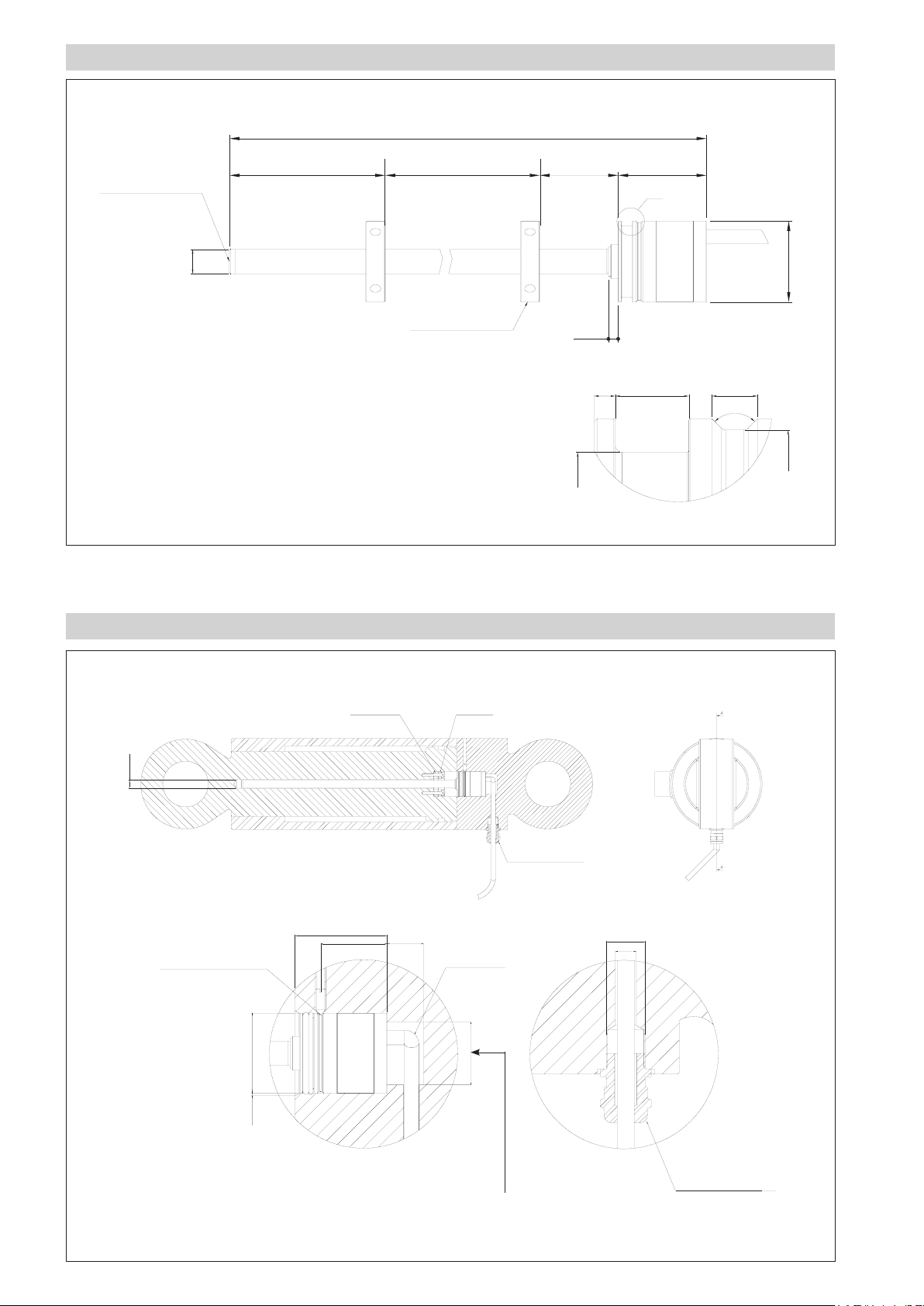
MECHANICAL DIMENSIONS
L (total length)
M4 thread
6mm depth
63.5 32 36
No active
zone
10
CE (electrical stroke)
Model
No active
zone
X
0
ø 33 h8-0.039
Magnet
4
Detail X
1.3 4.5 2.8
90°
ø 28.9 ±0.05 ø 31.6
MOUNTING INSIDE A CYLINDER
ø 13.5 min
38 min.
27.4 max 15 min
fixing screw seat
ISO 7434-M4x10-N
+0.09
ø 33 E8 +0.05
non-magnetic
spacer
magnet
R min. 10mm
ø 27
cable clamp for
cable ø 5-6.5mm
M12x1.5
ø8 max
Sv 1x60°
For RK-2-....-E version
the quote must be 30mm
cable clamp for
cable ø 5-6mm
Page 3
ELECTRICAL / MECHANICAL DATA
Model
Electrical stroke (C.E.) mm Model
Independent linearity < ± 0.02% F.S. (Min. ± 0.060 mm)
Max. dimensions (L) mm Model + 131.5 (excluding cable)
Repeatability mm < 0.01
Hysteresis < ± 0.005% F.S.
Sampling time msec 1 (1.5 for strokes from 1100 to 2000) (2 for strokes from ≥2000)
50 100 130 150 200 225 300 400 450 500 600 700 750 800 900 1000
1250 1500 1750 2000 2250 2500 2750 3000 3250 3500 3750 4000
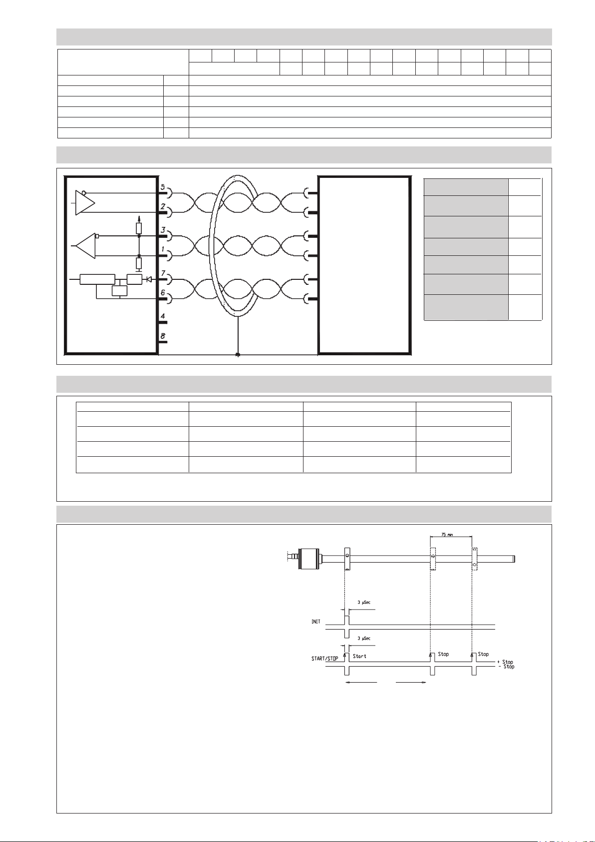
ELECTRICAL CONNECTIONS (RK- 2 - _ _ _ _ - S)
RK-2-_ _ _ _ -S Cable
Output (+) Gray
Output (-) Green
Input (+) Yellow
Input (-) Pink
Power supply + Brown
Power supply
GND Blue
15V
Controller
OP
Transducer
SP
N.C.
N.C.
Output (-)
IN
Output (+)
Input (-)
IN
Input (+)
24V
Power GND
Control system
ELECTRICAL CONNECTIONS (RK- 2 - _ _ _ _ - N/K/E)
RK-2-_ _ _ _ -N RK-2-_ _ _ _ -K RK-2-_ _ _ _ -E Cable
Output 0.1...10.1Vdc Output 0.1...5.1Vdc Output 4...20mA Yellow
Output GND Output GND Output GND Pink
Power supply + Power supply + Power supply + Brown
Power supply GND Power supply GND Power supply GND Blue
IMPORTANT: in case of cable lenggth shortening, after cutting the cable take care of soldering and insulating the green
and grey wires together
DIGITAL OUTPUT RK- 2 - _ _ _ _ - S
Series RK-2-_ _ _ _ -S magnetostrictive transducers supply
digital outputs in START/STOP format with RS422 differential
serial transmission.
The transducer requests an Initialisation pulse that launches
sampling. The following pulses are transmitted on the outputs:
Start: the Initialisation pulse retransmitted
Stop: the pulse corresponding to the position of each magnet.
The time between the Start pulse and the subsequent Stop pulses is proportional to the position of each magnet according to
the “Magnetostrictive wave propagation speed” constant, equal
to about 2900 m/Ssec.
P=
Time * 2900m/Sec
The correct propagation speed for each product is shown on
the product label.
Resolution in terms of metres is linked to the resolution used to measure time
The distance between Start
and Stop is proportional to
the position of the magnet
N cursor
1 µSec (1MHz ) ==> 2.9 mm
10 nSec (100 MHz ) ==> 0.029mm
1 nSec (1GHz ) ==> 2.9 µm
The measurement reference is the leading edge of the pulse.
Optimum width of the interrogation pulse is 3µSec, but the transducer works correctly for times from 1.5 to 5µSec
Page 4

ORDER CODE
Position
transducer
Model
Output
Start/Stop Start/Stop interface S
Analog 0.1...10.1Vdc interface (power supply 18...30Vdc) N
Analog 0.1...5.1Vdc interface (power supply 12Vdc) K
Analog 4...20mA interface (power supply 18...30Vdc) E
Mechanical and/or electrical characteristics differing from those in the standard
version may be arranged on request.
R K
2
FLOATING CURSOR (to order separately)
P C U R
Cursors
Cursor diameter 32.8
Cursor diameter 32.8 with 90° slit
Cursor diameter 25.4
022
023
024
PCUR022 PCUR023
0 0 0 0 X 0 X X
Connection cable to remote element
(PUR)
00 = 1 mt 02 = 2 mt 03 = 3 mt
04 = 4 mt 05 = 5 mt 10 = 10 mt
15 = 15 mt
0 0 0 X
X
PCUR024
Dimensions A B C Thickness
PCUR022
32.8 13.5 23.9
PCUR023 7.9
PCUR024 25.4 13.5 -
The PCUR022 is supplied with: The PCUR023 is supplied with:
N° 8 Brass nuts M4 N° 4 Brass nuts M4
N° 8 Brass washers D4 N° 4 Brass washers D4
N° 4 Brass screws M4x25 N° 2 Brass screws M4x25
OPTIONAL ACCESSORIES (to order separately)
Cable clamp PRE060
Page 5

OPTIONAL REMOTE ELECTRONICS FOR RK-2- _ _ _ _ -S
Available in two versions
• With analog voltage or current output for displacement and
speed measurement (model EKA)
Main features
• Option for zero and full-scale adjustment over 100% of the
stroke via “magnetic pen” (available on model EKA)
• Power range 10...30Vdc
• Connection to remote electronics via connector or screw
terminal (PUR cable, ø 5 mm)
• MAX distance of remote electronics from sensor: 50 m
TECHNICAL DATA (EKA)
Measurement taken Displacement / Speed
Speed range 0.1 ... 10 m/s
Accuracy speed < 2 % (in all F.S.)
Speed calculation time Sampling time + 500µsec
Resolution 16 bit
Output signal
Nominal power supply 10...30Vdc 10...30Vdc
Max. power ripple 1Vpp 1Vpp
Current consumption
Output load 2 KΩ < 500 Ω
Max. output ripple < 5 mV pp < 5 mV pp
Max. output value 10.6 V 25 mA
Electrical isolation 200 V 200 V
Protection against
polarity inversion
Protection against
overvoltage
Self-resetting
internal fuse
0...10V (N,P)
0...5V (K)
Depends on power supply voltage:
max 70mA
with power supply of 30Vdc *
max 85mA
with power supply of 24Vdc *
max 110mA
with power supply of 18Vdc **
max 200mA
with power supply of 10Vdc **
* peak 0,2A at power
** peak 0,4A at power
YES YES
YES YES
YES YES
4...20mA (E,F)
0...20mA (B,C)
MECHANICAL DIMENSIONS
34.5
ø4.4
zero adjustment
(only EKA)
71
80
40
span adjustment
(only EKA)
40
80
28.8
Page 6
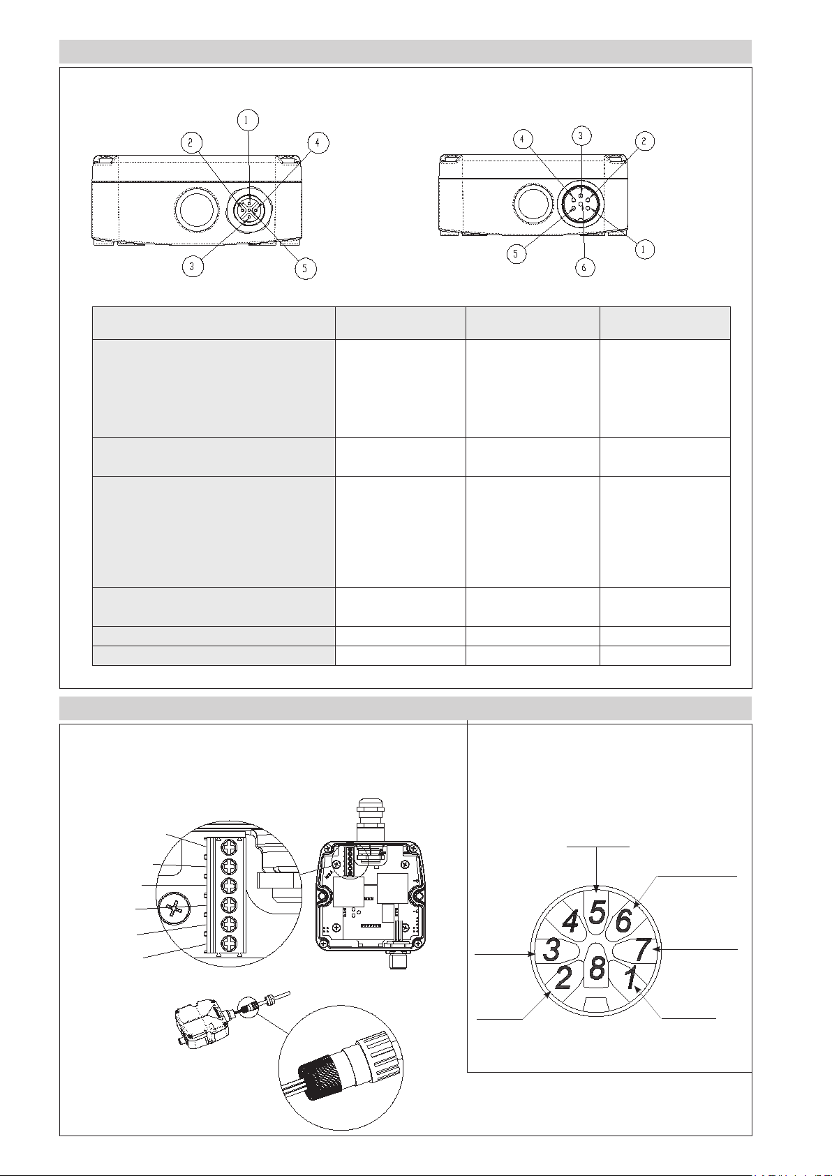
ELECTRICAL CONNECTIONS
RK-_-_ _ _ _-S-EKA- _ -M-_ - _ RK-_-_ _ _ _-S-EKA- _ -B-_ - _
Function EKA-_-M-_-_
M12 5-pin
EKA-_-B-_-_
M16 6-pin DIN 45322
Optional cable
for M12
Output 1 (displacement)
0...10V
0...5V
1 1 Brown
4...20mA
0...20mA
GND shift 1
(0V)
2 2 White
Output 2 reverse displacement, or speed
depending on the model
0...10V
0...5V
3 3 Blue
4...20mA
0...20mA
GND shift 1/2
(0V)
2 4 White
Power supply + 5 5 Grey
Power supply - 4 6 Black
INTERCONNECTION BETWEEN PRIMARY SENSOR AND REMOTE ELECTRONICS
BROWN
power supply +
BLUE
power supply GND
YELLOW input +
PINK input -
GREY output +
GREEN output -
RK- _ - _ _ _ _ - S-EKA - _ - _ - R - _
RK- _ - _ _ _ _ - S-EKA - _ - _ - M - _
(interconnection with wire clamp and screw terminals) (interconnection with M12 8-pin connector)
GREEN output -
PINK
input
GREY
output +
BLUE power supply
-
power supply +
GND
BROWN
YELLOW
input +
Attention:
do all wiring BEFORE powering the electronics
(i.e., with unit off).
Page 7

CALIBRATION WITH MAGNETIC PEN (option RK- _ - _ _ _ _ -S-EKA-D- _ - _ - _)
The magnetic pen is needed to calibrate the useful stroke of the transducer in a manner other than as configured in the factory (default).
• CALIBRATION OF ZERO POINT
when the magnet is at the required zero point, position the magnetic pen in the
ZERO zone for a time between 0.5 and 10 seconds.
• CALIBRATION OF FULL-SCALE POINT
when the magnet is at the required full-scale point, position the magnetic pen in the
FS zone for a time between 0.5 and 10 seconds.
• SAVING THE NEW CALIBRATION
position the magnetic pen in the ZERO or FS zone for a time between 10 and 60
seconds. The programmed configuration will be saved and active at the next powerup.
• RESTORING FACTORY DEFAULT CALIBRATION
position the magnetic pen in the ZERO or FS zone for more than 60 seconds.
This will restore the original factory calibration in the internal EEPROM.
Factory
Zero button with Magnet in P1
FS button with magnet in P2
F.Z.O: 0V, 4mA, 0mA, -10V, -5V
F.F.S.O: 10V, 20mA, 0mA,
+10V, +5V
ORDER CODE (RK-2 with EKA analog remote electronics)
Position
transducer
Model
Analog output A
Analog output with
zero and span setting D
Output connector type
M12, 5-pin connector output M
DIN 45322 6-pin
connector output B
Type of connection to the
primary sensor
Internal screw terminal R
M12, 8-pin connector M
Output
0...10Vdc 1 Cursor, double output position (standard) N
0...10Vdc 1 Cursor, position and speed P
4...20mA 1 Cursor, double output position E
4...20mA 1 Cursor, position and speed F
Available on request
0...20mA 1 Cursor, double output position B
0...20mA 1 Cursor, position and speed C
0...+5Vdc 1 Cursor, double output position K(*)
2 X
R K
S - E K A
0 0 0 0 X
Output of speed
Only for analogic output
option C, F, P
Max. measurable speed: 0.1 ÷ 10.0 m/s
00.0 Function not required
Power supply
S 10...30V (standard)
Connection cable to remote element
00 = 1 mt 02 = 2 mt 03 = 3 mt
04 = 4 mt 05 = 5 mt 10 = 10 mt
15 = 15 mt
Mechanical and/or electrical characteristics
differing from those in the standard version
may be arranged on request.
0 X X
(*) The maximum stroke for the K version is 1200mm
Page 8

OPTIONAL CONNECTORS FOR EKA OUTPUT (to order separately)
For M outputs, M12 thread connector
(for RK-_-_ _ _ _-S-EKA-_-M-_-_)
Cable camp
for ø6.5 cable
Code: CON031 5-pin
CON041 5-pin
For B outputs, M16 thread connector
(for RK-_-_ _ _ _-S-EKA-_-B-_-_)
Code: CON021 6-pin
CON022 6-pin
CON023 6-pin
Connector extraction length: 10mm
OPTIONAL CABLES FOR EKA OUTPUT
(to order separately)
Cable Code (for RK-_-_ _ _ _-S-EKA-_-M-_-_-_)
Length “L”
Straight cable Cable to 90°
2 mt CAV011 CAV021
5 mt CAV012 CAV022
10 mt CAV013 CAV023
15 mt CAV015 CAV024
CODE
CON031
IP67 - IEC 48B
Cable camp for
ø6 - ø 8 cable
CON041
IP67
Cable camp
for ø5 cable
CON021
IP40 - EMC
Cable camp
for ø6 - ø8 cable
CON022
IP67 - EMC
Cable camp
for ø5 - ø8 cable
OTHER ACCESSORIES FOR USE WITH EKA
(to order separately)
M12, 8-pin axial male connector for interconnection CON460
Magnetic pen to calibrate remote electronic
(model EK-A-D)
CON023
IP67 - EMC
PKIT312
Sensors are manufactured in compliance with:
- EMC 2014/30/EU compatibility directive
- RoHS 2011/65/EU directive
GEFRAN spa reserves the right to make any kind of design or functional modification at any moment without prior notice.
DTS_RK-2_04-2016_ENG
 Loading...