

Page 1

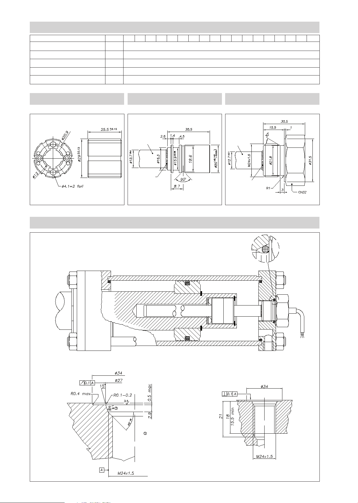
Version Flange (X) Std
Version Flange (M)
M24x1,5 thread
SEALING
ZONE
IP67 0,2 BAR
SEALING
ZONE
AT 250 BAR
Case
3-pole
cable PUR
3-pole
cable PUR
Welding
Welding
Stem
Sealing
gasket
PMI-SLE
RECTILINEAR DISPLACEMENT TRANSDUCER WITH
MAGNETIC DRAG (analog output)
Applicative characteristics
• The PMI-SLE transducer, is the amplified version of
the PMI-SL, a product designed for all inside cylinder
applications which require a smaller transducer (the
rod diameter is only 12,7 mm).
• The PMI Slim offers the same robustness: stainlessteel body, IP67 protection level, and pressure resistance up to 250 bar (400 bar peak)
• Available with flanged or threaded heads, to guarantee mechanical compatibility with all main cylinder
types
• Patented solution
• Ideal for applications inside hydraulic cylinders,
demanding simple solutions which guarantee measurement repeatability.
MECHANICAL DIMENSION
TECHNICAL DATA
Useful electrical stroke (C.E.U.)
50/100/150/200/250/300/350/400/450/500/550/600/750/800/850/900/950
/1000
Independent linearity (within C.E.U.)
± 0,35%
Resolution
Infinite
Repeatability
≤ 0.08 mm
Hysteresis
< 250µm
Life
6
> 25x10
Displacement sensitivity (no hysteresis))
from 0.05 to 0.1 mm
Tracking error
see table
Displacement speed
standard < 5 m/s
Max. acceleration
< 10m/s2 max displacement
Cursor dragging force
≤ 0.5 N
Vibrations
5...2000Hz, Amax =0,75 mm amax. = 20 g
Shock
50 g, 11ms.
Power supply voltage
10...30Vdc (see the load diagram)
Max power consumption
35mA
Min load allowed
see the load diagram
Output signal 4...20 mA
- ZERO position (4mA): between 1% and 3% of the C.E.U.
- SPAN position (20mA): between 96% and 99% of the C.E.U.
Electrical connection
1 mt. 3-pole shielded cable
Sampling time
≤ 1 ms
Noise on output
< 0.08%FS RMS
Electrical isolation
> 100 MΩ at 45 Vdc = 1 bar, 2 s
Zero and FSO temperature drift
< 0.02%FS/°C
Polarity inversion protection
Yes
Pulse overvoltage protection
Yes
Working temperature
-30...+80°C
Storage temperature
-40...+100°C
Protection level
IP67
Material for transducer case
Steel AISI 304
m strokes, or > 100x106 maneuvers, whichever is less
Page 2
MECHANICAL / ELECTRICAL DATA
MODEL
Useful electrical stroke (C.E.U.) + 1/-0
Theoretical electrical stroke (C.E.T.) ± 1
Independent linearity (within C.E.U.)
Mechanical stroke (C.M.)
Lenght “A” ±1
mm
mm
± %
mm
mm
50
100 150 200 250 300 350 400 450 500 550 600 750 800 850 900 950 1000
Model
C.E.U. + 1
0.35
C.E.U. + 5
C.E.U. + 100.2
PCUR010 CURSOR STANDARD FLANGE (X) THREADED FLANGE (M)
Stem
Welding
INSTALLATION INSIDE THE CYLINDER
Flange Version (M) thread M24x1,5
Stem
Welding
O-Ring recommended
PARKER 2-117 20,29x2,62
Material NBR 90 Shore-A
Compound PARKER N552-90
O-ring surface must be free of spiral
or longitudinal scratches Ro 1,6μm for
O-rings with NOT PULSING pressure
Ro 0,8μm for O-rings with PULSING
pressure
O-Ring recommended PARKER 2-117
20,29x2,62 Material NBR 90 Shore-A
Compound PARKER N552-90
Page 3

246810 12 14 16 18 20 22
INSTALLATION INSIDE THE CYLINDER
Flange Version (X) standard
Cylinder shaft
Potentiometer
rod
No. 2 corrugated washers must be
assembled in a pack so to prevent
any axial movements of cursor and
Non-magnetic spacer
thickness 2 + -0.1
Groove in cylinder shaft, for
assembly of cursor, corrugated
washers and snap ring
to allow cursor to rotate toward
piston shaft
Non-magnetic spacer
thickness 2 + -0.1
Cursor
OR Seal
recommended:
OR119 NBR-90
Cursor
Snap ring
Locking
screw
Cursor assembly PMI-SL with
screws and magnetic spacer
ELECTRICAL CONNECTIONS
CONTROLLER
AMPLIF.
Connected to the transducer’s housing
(do not connect to the panel side)
TRACKING ERROR
2
1,8
1,6
1,4
1,2
1
0,8
Error (mm)
0,6
0,4
0,2
Acceleration (g)
Supply +
Supply -
Output -
Output +
brown
blue
yellow
Connection
side
Cursor housing size PMI-SL assembly with
corrugated washers and non-magnetic spacer
thickness 2+-0.1
INSTALLATION INSTRUCTIONS
• Respect the indicated electrical connections
• When calibrating the transducer, be careful to set the stroke
so that the output does not drop below 1% or rise beyond
99% of the 4/20mA output.
LOAD DIAGRAM
1000
900
800
700
600
500
400
Load (Ohm)
300
200
100
0
10 12 14 16 18 20 22 24 26 28 30
Area of use
Power supply (V)
Page 4

ACCESSORIES (series)
Standard magnetic cursor PCUR010
ORDERING CODE
Displacement
transducer
4...20mA analog output
3-pole PUR cable output
3x0.25, 1 mt
Model
Standard flange
Threaded flange M24x1.5
Ex.: PMI-SLE-F-0400-X 0000X000XX00XXX
PMI SLE displacement transducer, 4...20mA analog output, useful electrical stroke (C.E.U.) 400mm, standard flange, no certificate attached,
cable length 1 mt.
P M I S L
F
X
M
E
No certificate attached
Linearity curve to be attached
0 0 0 0 X 0 0 0 X X X X X
0
Version F cable length
L
1 mt cable (standard)
2 mt cable
3 mt cable
4 mt cable
5 mt cable
10 mt cable
15 mt cable
Sensors are manufactured in compliance with:
- EMC 2004/108/CE compatibility directive
- RoHS 2002/95/CE directive
Electrical installation requirements and Conformity certificate are available on our web site: www.gefran.com
GEFRAN spa reserves the right to make any kind of design or functional modification at any moment without prior notice.
00
02
03
04
05
10
15
GEFRAN spa
via Sebina, 74
25050 PROVAGLIO D’ISEO (BS) - ITALIA
ph. 0309888.1 - fax. 0309839063
Internet: http://www.gefran.com
DTS_PMI-SLE_03-2016_ENG
 Loading...