

Page 1
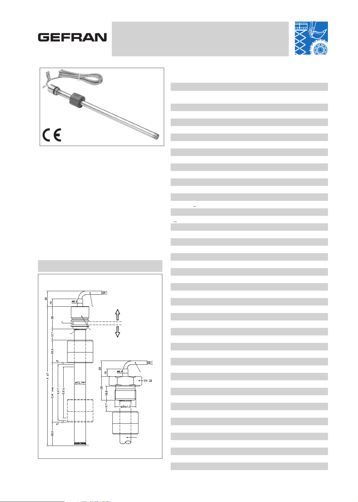
Version Flange (X) Std
Version Flange (M)
M24x1,5 thread
SEALING
ZONE
IP67 0,2 BAR
SEALING
ZONE
AT 250 BAR
Case
3-pole
cable PUR
3-pole
cable PUR
Welding
Welding
Stem
Sealing
gasket
PMI-SL
RECTILINEAR DISPLACEMENT TRANSDUCER
WITH MAGNETIC DRAG
Applicative characteristics
• The PMI-SL transducer, an evolution of the PMI-12,
is designed for all inside cylinder applications which
require a smaller transducer.
For this reason, the diameter has been reduced to
12.7 mm.
• The PMI Slim offers the same robustness as the PMI-12:
AISI 316 stainless steel body, IP67 protection level,
and pressure resistance up to 250 bar (400 bar peak)
• Available with flanged or threaded heads, to guarantee mechanical compatibility with all main cylinder
types
• Patented solution
• Ideal for applications inside hydraulic cylinders,
demanding simple solutions which guarantee measurement repeatability.
MECHANICAL DIMENSION
Important: all the data reported in the catalogue linearity and tem-
perature coefficients are valid for sensor utilization as a ratiometric
device with a max current across the cursor Ic ≤ 0.1 µA.
TECHNICAL DATA
Useful electrical stroke (C.E.U.)
50/100/150/200/250/300/350/400/450/500/550/600/750/800/850/900/950
/1000
Independent linearity (within C.E.U.)
± 0,35%
Resolution
Infinie
Repeatability
≤ 0.08 mm
Hysteresis
< 250µm
Life
6
> 25x10
Electrical connection
1 mt 3-pole shielded cable
Displacement speed
standard < 5 m/s
Max. acceleration
< 10m/s2 max displacement
Cursor dragging force
≤ 0.5 N
Vibrations
5...2000Hz, Amax =0,75 mm amax. = 20 g
Shock
50 g, 11ms.
Displacement sensitivity (no hysteresis)
from 0.05 to 0.1 mm
Tracking error
see table
Tolerance on resistance
± 20%
Recommended cursor current
< 0,1 µA
Maximum cursor current in case of bad performances
10mA
Maximum applicable voltage
see table
Electrical isolation
>100MΩ at 500V=, 1bar, 2s
Dielectric strenght
< 100µA at 500V~, 50Hz, 2s, 1bar
Dissipation at 40°C (0W at 120°C)
see table
Thermal coefficient of resistance
-200...+200 ppm/°C typical
Actual Temperature coefficient of the output voltage
≤ 5 ppm/°C typical
Working temperature
-30...+100°C
Storage temperature
-50...+120°C
Material for transducer case
AISI 304
m strokes, or > 100x106 maneuvers, whichever is less
Page 2
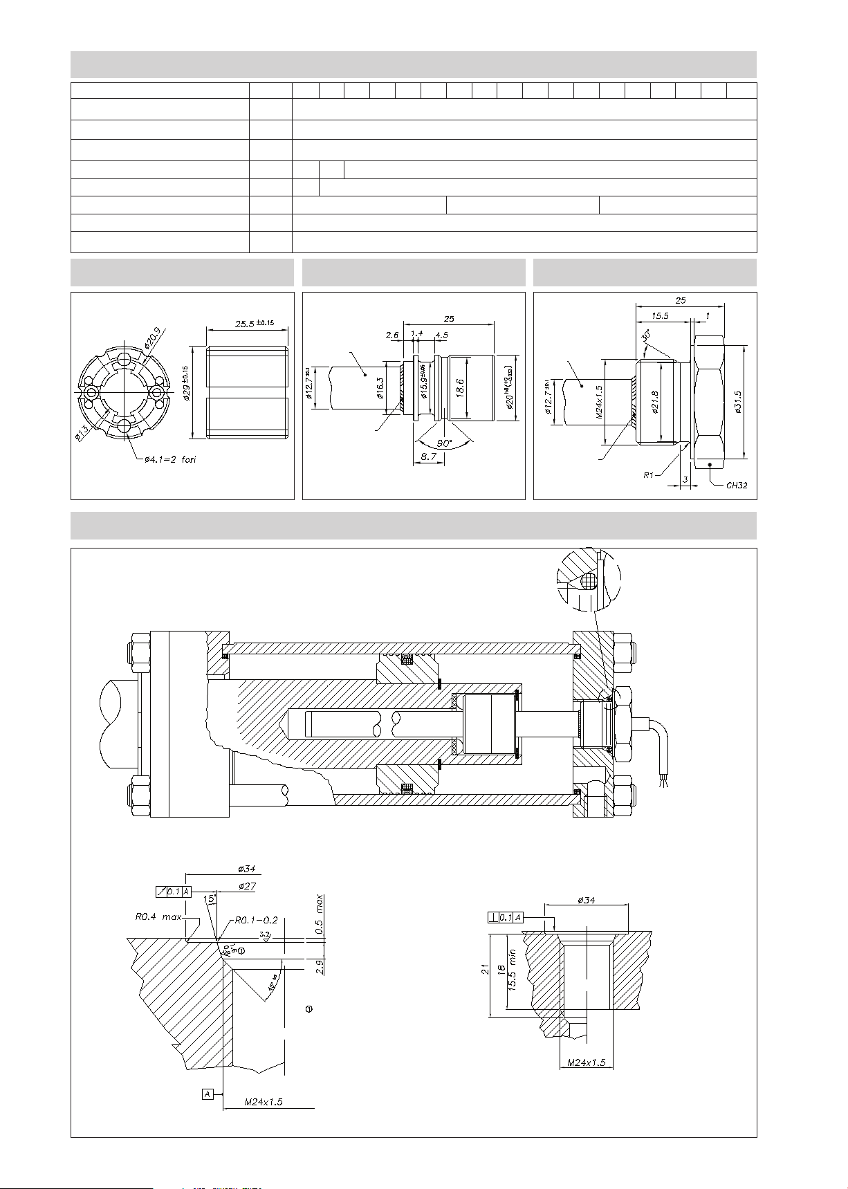
MECHANICAL / ELECTRICAL DATA
MODEL
Useful electrical stroke (C.E.U.) + 1/-0
Theoretical electrical stroke (C.E.T.) ± 1
Independent linearity (within C.E.U.)
Dissipation at 40°C (0W at 120°C)
Max applicable voltage
Resistance (C.E.T.)
Mechanical stroke (C.M.)
Case Lenght “A” ±1
mm
mm
± %
W
V
kΩ
mm
mm
50
100 150 200 250 300 350 400 450 500 550 600 750 800 850 900 950 1000
Model
C.E.U. + 1
0.35
1 2
40
3
60
5 10 20
C.E.U. + 5
C.E.U. + 94.7
PCUR010 CURSOR STANDARD FLANGE (X) THREADED FLANGE (M)
stem
welding
INSTALLATION INSIDE THE CYLINDER
Flange Version (M) thread M24x1,5
stem
welding
O-Ring recommended
PARKER 2-117 20,29x2,62
Material NBR 90 Shore-A
Compound PARKER N552-90
O-ring surface must be free of spiral
or longitudinal scratches Ro 1,6μm for
O-rings with NOT PULSING pressure
Ro 0,8μm for O-rings with PULSING
pressure
O-Ring recommended PARKER
2-117 20,29x2,62 Material NBR 90
Shore-A
Compound PARKER N552-90
Page 3

INSTALLATION INSIDE THE CYLINDER
Flange Version (X) standard
Cylinder shaft
Potentiometer
rod
No. 2 corrugated washers must be
any axial movements of cursor and
Non-magnetic spacer
thickness 2 + -0.1
Groove in cylinder shaft, for
assembly of cursor, corrugated
washers and snap ring
assembled in a pack so to prevent
to allow cursor to rotate toward
piston shaft
Non-magnetic spacer
thickness 2 + -0.1
Cursor
OR Seal
recommended:
OR119 NBR-90
Cursor
Snap ring
Locking
screw
Cursor assembly PMI-SL with
screws and magnetic spacer
ELECTRICAL CONNECTIONS
TRACKING ERROR
Cable output
blue
INSTALLATION INSTRUCTIONS
• Make the specified electrical connections
(DO NOT use the transducer as a variable resistance)
yellow
• When calibrating the transducer, be careful to set the stroke so
that the output does not drop below 1% or rise above 99% of
brown
Connection side
2
1,8
1,6
1,4
1,2
1
0,8
Error (mm)
0,6
0,4
0,2
246810 12 14 16 18 20 22
Acceleration (g)
the voltage level.
Cursor housing size PMI-SL assembly with
corrugated washers and non-magnetic spacer
thickness 2+-0.1
Page 4

ORDER CODE
Displacement
transducers
3-pole PUR cable output
3x0.25, 1 mt
Model
Standard flange
Threaded flange M24x1.5
Ex.: PMI-SL-F-0400-X 0000X000XX00XXX
PMI SL displacement transducer, cable output, useful electrical stroke (C.E.U.)
400mm, standard flange, no certificate attached, cable length 1 mt.
P M I S L
F
X
M
No certificate attached
Linearity curve to be attached0L
0 0 0 0 X 0 0 0 X X X X X
Version F cable length
1 mt cable (standard)
2 mt cable
3 mt cable
4 mt cable
5 mt cable
10 mt cable
15 mt cable
ACCESSORIES (standard)
Standard magnetic cursor PCUR010
GEFRAN spa reserves the right to make any kind of design or functional modification at any moment without prior notice
00
02
03
04
05
10
15
DTS_PMI-SL_03-2016_ENG
 Loading...