

Page 1
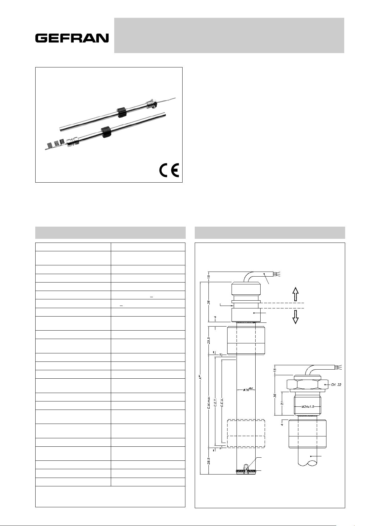
PMI12
RECTILINEAR DISPLACEMENT TRANSDUCER
WITH MAGNETIC DRAG
Main characteristics
• The PMI-12 transducer is designed for use inside oilpressure cylinders, applications that demand high
strength.
• The AISI316 stainless steel body and elevated protection
level permit installation in cylinders with pressures up to
250 bar (400 bar peak).
• Available with internal flanges or external threads to guarantee mechanical compatibility with all principal cylinder
types.
• Patented
TECHNICAL DATA
Useful electical stroke (C.E.U.) 50 to 1000 mm
Independent linearity
(within C.E.U.)
Resolution Infinite
Repeatibility ≤ 0.08 mm
Electrical connection 1 mt. 3-pole shielded cable
Displacement speed
Max. acceleration
Cursor dragging force ≤ 0.5 N
Vibrations 5...2000 Hz, Amax = 0.75 mm
Shock 50 g, 11 ms
Displacement sensitivity
(no hysteresis)
Tracking error see table
Tolerance on resistance ± 20%
Recommended cursor current < 0.1 µA
Maximum cursor current in
case of bad performances
Maximum applicable voltage see table
Electrical isolation > 100 MΩ at 500 V = 1 bar, 2 s
Dielectric strength < 100 µA at 500 V~ 50 Hz,
Dissipation at 40°C
(0 W at 120°C)
Thermal coefficient of resistance -200...+200 ppm/°C typical
Actual Temperature coefficient
of the output voltage
Working temperature -30...+100°C
Storage temperature -50...+120°C
Material for transducer case Steel AISI 316
Important: All the data reported in the catalogue linearity and temperature
coefficients are valid for a sensor utilization as a ratiometric device with a
max current across the cursor circuit Ic ≤ 0.1 mA.
< 10m/s2 max displacement
see table
standard < 5 m/s
amax = 20 g
0.05 to 0.1 mm
10 mA
2 s, 1 bar
see table
≤ 5 ppm/°C typical
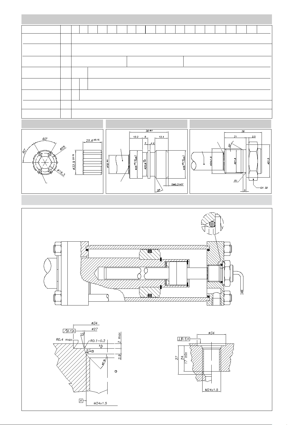
MECHANICAL DIMENSION
Version Flange (X) Std
Sealing
gasket
3 pole
cable
Case
Welding
Inside thread
M4 6 mm
deepth
Welding
SEALING
ZONE IP67
0,2 BAR
SEALING
ZONE
AT 250 BAR
Version Flangie (M)
M24x1,5 thread
Stem
Page 2
MECHANICAL / ELECTRICAL DATA
MODEL
250 300 350 400 450 500 750 800 850 900 950 100050 100 150 200 550 600 650 700
Useful electrical stroke
(C.E.U.) + 1 / -0
Theoretical electrical
stroke (C.E.T.) ± 1
Resistance
( C.E.T.)
Independent linearity
(within C.E.U.)
Dissipation at 40°C
(0W at 120°C)
Max applicable
voltage
Mechanical stroke CM
Case Lenght (A)
mm
mm
kΩ
±%
W
V
mm
mm
PCUR032 CURSOR
40
0,1
Model
C.E.U. + 1
5
10 20
0,05
21
3
60
C.E.U. + 5
C.E.U. + 97
STANDARD FLANGE (X) THREADED FLANGE (M)
Welding
Stem
Stem
N° 4 Holes ø 4.1
Welding
INSTALLATION INSIDE THE CYLINDER
Flange Version (X) thread M24x1,5
O-Ring recommended
PARKER 2-117 20,29x2,62
Material NBR 90 Shore-A
Compound PARKER N552-90
O-ring surface must be free of
spiral or longitudinal scratches
Ro 1,6μm for O-rings with NOT
PULSING pressure Ro 0,8μm for
O-rings with PULSING pressure
O-Ring recommended PARKER
2-117 20,29x2,62
Material NBR 90 Shore-A
Compound PARKER N552-90
Page 3
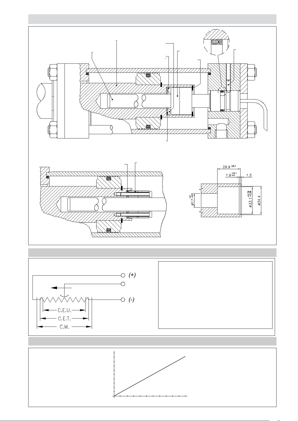
INSTALLATION INSIDE THE CYLINDER
Flange Version (X) standard
Cylinder shaft
Potentiometer
rod
Non-magnetic spacer
thickness 2 + -0.1
Groove in cylinder shaft, for
assembly of cursor, corrugated
washers and snap ring
No. 2 corrugated washers must
be assembled in a pack so to
prevent any axial movements
of cursor and to allow cursor to
rotate toward piston shaft
Non-magnetic spacer
thickness 2 + -0.1
Cursor
OR Seal
recommended:
OR3081 NBR-90
Cursor
Snap ring
Locking
screw
Assembly cursor PMI with
screws and Non-magnetic
spacer thickness
ELECTRICAL CONNECTIONS
TRACKING ERROR
Cable output
blue
yellow
brown
Connection side
2
1,8
1,6
1,4
1,2
1
0,8
Error (mm)
0,6
0,4
0,2
246810 12 14 16 18 20 22
Acceleration (g)
Cursor housing size PMI-SL assembly with
corrugated washers and non-magnetic spacer
thickness 2+-0.1
INSTALLATION INSTRUCTIONS
• Respect the indicated electrical connections (DO NOT use
the transducer as a variable resistance)
• When calibrating the transducer, be careful to set the stroke
so that the output does not drop below 1% or rise beyond
99% of the supply voltage.
Page 4
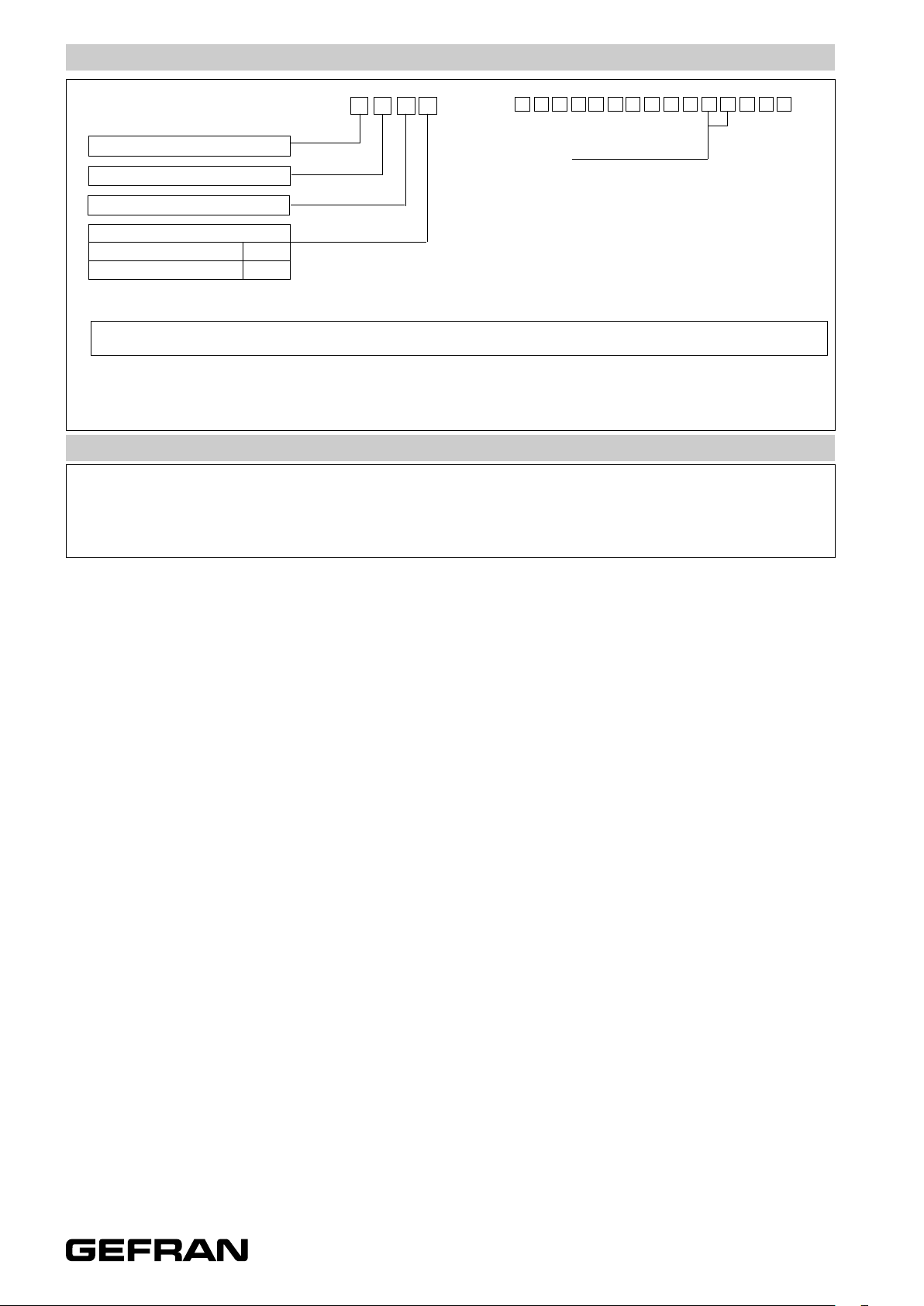
ORDER CODE
Displacement transducers PMI
Dimensions 1/2”
3-pole PUR cable output 3x0,25 1m
12 F
0 0 0 0 X 0 0 0 X X 0 0 X X X
CABLE LENGHT (1mt F standard version)
F output 00 =1mt 02 =2mt 03 =3mt 04 =4mt 05 =5mt
10 =10mt 15 =15mt
Model
FLANGE
Standard X
Threaded M24x1,5 M
If requested, it is possible to supply models with non-standard mechanical and/or electrical features
Ex.:PMI-12-F-400-X 0000-X000-XX-00-XXX
PMI 12 model transducer, useful electrical stroke (C.E.U.) 400mm.
ACCESSORIES
Series
• Standard magnetic cursor: PCUR032
GEFRAN spa reserves the right to make any kind of design or functional modification at any moment without prior notice
DTS_PMI12_05-2015_ENG
 Loading...