

Page 1
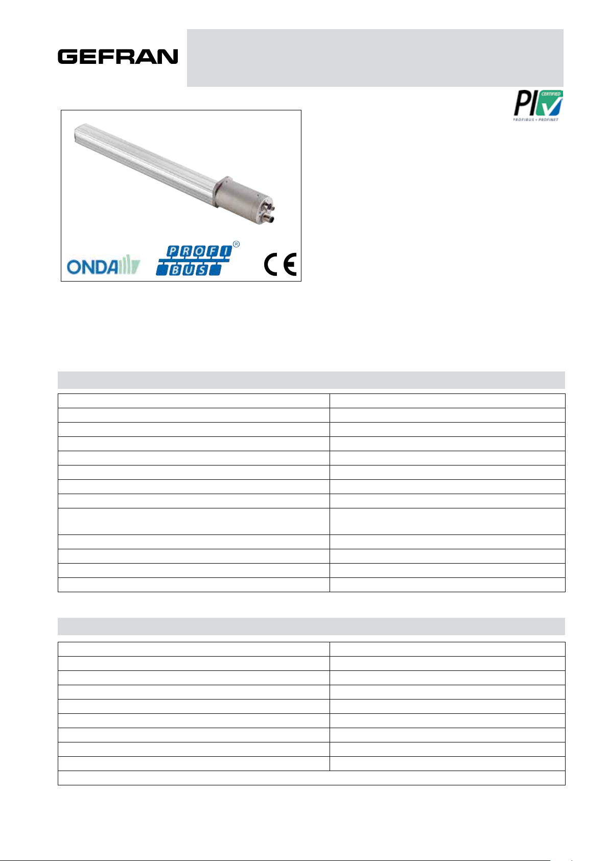
MK4 P (with ONDA technology)
CONTACTLESS MAGNETOSTRICTIVE LINEAR POSITION TRANSDUCER
(PROFIBUS OUTPUT)
Main features
• ONDA technology
• Stroke: 50 to 4000mm
• Position resolution settable via software up to 1 μm
• Speed resolution up to 0.25 mm/sec
• Conforms to CE directives (EN 50081-1 50082-1)
• Vibration-resistant (DIN IEC68T2/6 12 g)
• IP67 protection rating
• Controls up to four cursors simultaneously
• Two M12 connectors for simplified connection to Profibus and
one M8 connector for separate connection to power supply
(transducer can be powered without having to be connected to
bus)
• Local intelligence
• Profibus DPV0 interface on RS485 in conformity to IEC 61158
Contactless absolute linear position transducer with ONDA magnetostrictive technology. The Profibus fieldbus interface integrates in com-
plex systems with long communication distances, guaranteeing rapid and secure data transmission.
The absence of contact on the cursor eliminates all wear and ensures almost unlimited life of the transducer.
Its many advantages include smaller size for easier installation, high protection rating for use in harsh environments, excellent linearity,
repeatability, and resistance to vibration and shock, guaranteeing exceptional reliability.
TECHNICAL DATA
ELECTRICAL DATA
(*) Uses 50V 2J snubber
Model 50 to 4000 mm
Measurement taken Position / Speed
Position read sampling time (typical) 1 ms
Shock test DIN IEC68T2-27 100g - 11ms - single blow
Vibrations DIN IEC68T2-6 12g / 10...2000Hz
Shift speed ≤10 m/s
Max. acceleration ≤ 100 m/s2 shift
Resolution up to 1μm
Cursor type Sliding cursor
Separate floating cursor
Work temperature -40...+85°C
Storage temperature -40...+100°C
Coefficient of temperature 20ppmFS / °C
Protection rating IP67
Output signal Profibus DPV0 on RS485
Rated power supply 10-32 Vdc
Max power supply ripple 1Vpp
Max. draw 2W
Min. load on output RS485 standard
Electrical isolation 500V (*) (D.C. power supply/ground)
Polarity inversion protection YES
Overvoltage protection YES
Self-resetting internal fuse YES
Page 2
ELECTRICAL / MECHANICAL DATA
Model
Electrical
Stroke (E.S.)
Independent
linearity
Max.
dimensions (A)
Repeatability mm < 0.01 (limited by resolution of output value)
Hysteresis ±%F.S < ± 0.005% FS (0.010 mm minimum)
Sampling time ms 1 (for strokes up to 800) 2 (for strokes from 850 to 2000) 4 (for strokes >2000) (*)
* Note: the sampling time doubles for models using 3 and 4 cursors
±%F.S
50 75 100 130 150 175 200 225 250 300 350 360 400 450 500 550 600 650 700 750 800 850 900 950 1000
1100 1200 1250 1300 1400 1500 1750 2000 2250 2500 2750 3000 3250 3500 3750 4000
mm Model
Typical :≤ ± 0.02 % FS with oating cursor (value depends on distance between cursor and sensor body)
mm Model + 181.7
Typical : ≤ ± 0.01 %FS (min ± 0.060mm) with sliding cursor
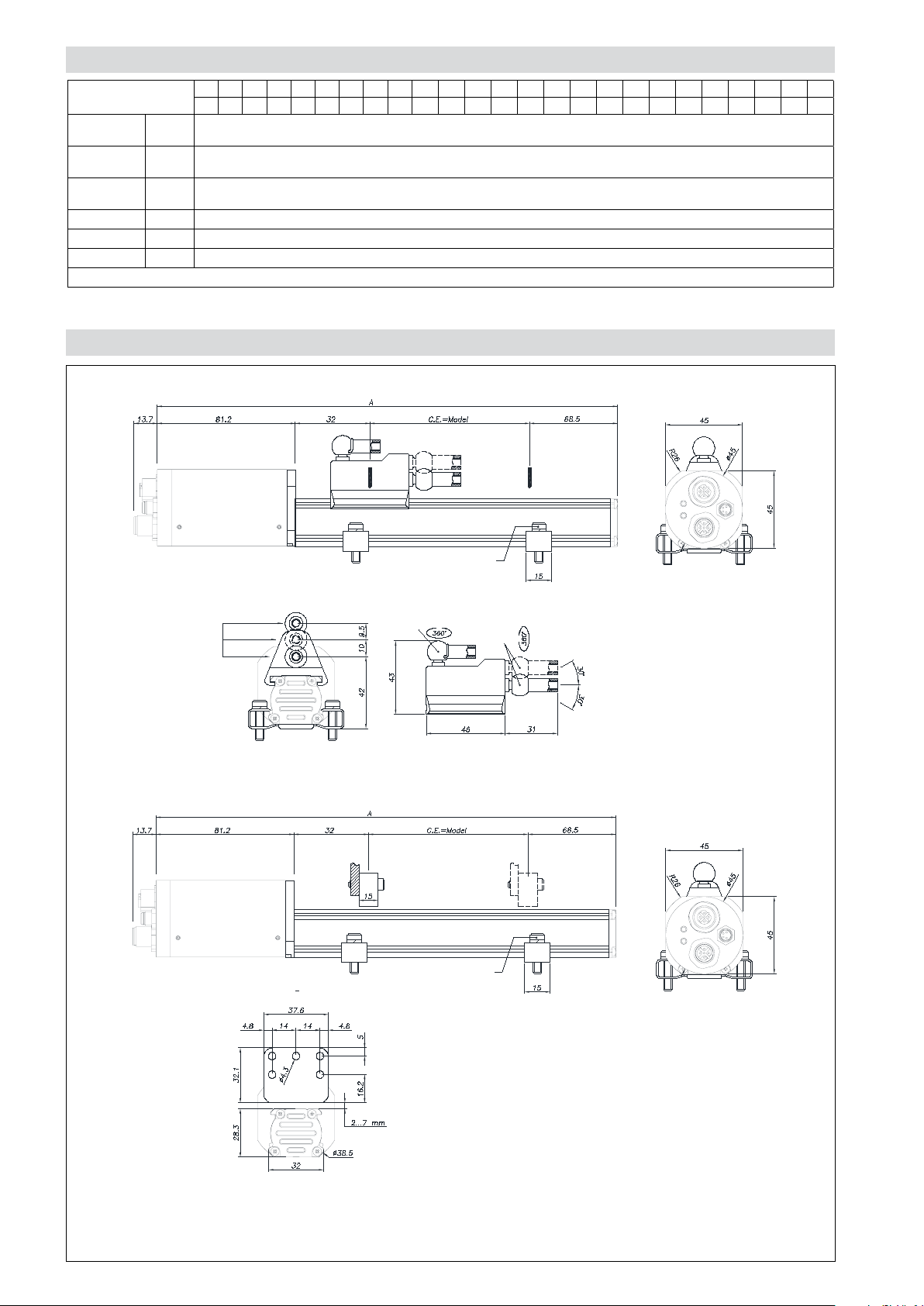
MECHANICAL DIMENSIONS
Version MK4PW with sliding magnetic cursor
M5 holes
depth 10
Closing force
< 1.1 Nm
Angle joint
Axial joint
Version MK4PW with floating magnetic cursor
Closing force
< 1.1 Nm
Tolerated
lateral
offset ±2
Note
1) For strokes > 2500mm use sliding or floating cursors at a max. height of 4mm
2) On multicursor versions, the cursors must work at the same distance and temperature and be at least 75 mm apart
Page 3

PROFIBUS STRUCTURE AND CONNECTION
A
B
C
2
4
1
34
2
2
4
MK4PW OUTPUT
Red LED
Green LED
RED LED GREEN LED DESCRIPTION
Off Off Transducer not powered
Off
Flashing
(f= 1 HZ)
Off On Transducer in cyclical communication with Master (state= Data_Exch).
On On
1 5VD_ISO
2 LINE_A/N
3 GND_ISO
4 LINE_B/P
5 GROUND
CONNECTOR A
(M12 FEMALE)
CONNECTOR B
(M8 MALE)
1 24V
2 N.C.
3 0V
4 N.C.
CONNECTOR C
(M12 MALE)
1 5VD_ISO
2 LINE_A/N
3 GND_ISO
4 LINE_B/P
5 GROUND
1
5
3
5
3
1
Transducer ready to start communicating with Master (state =Wait Parm)
1. At power-on: signals correct functioning of LEDs.
2. In Data-Exchange mode: signals magnet error (number of magnets measured
incompatible with current parameterization).
PROFIBUS STRUCTURE AND CONNECTION
A Profibus network lets you connect peripheral Slave devices (transducers or actuators) to Class 1 Master central control units (typically
PLCs).
The network software is installed with a Class 2 Master containing a database with the GSD files of all connected devices. The network
is designed and parameterized with a graphics tool, then the configuration is downloaded to the Class 1 Masters in the network.
The Class 1 Master(s) start(s) the communication process with the peripheral devices according to the configuration received from the
Class 2 Master.
This process includes an initial data exchange regarding Slave identification, parameterization, and configuration.
When this phase is done, application management begins with exchange of process data on the network.
The GSD file contains all information on device identification, supported functions, and length/format of data packets.
Connection with two M12 connectors + 1 M8 connector:
• no T connection required
• standard M12 and M8 connectors
• separate power supply line (ideal for use of programmer)
• for power supply: use a shielded cable with metal connector and shield
connected to connector case
Class 2 Master
Slave
Slave
Slave
PROFIBUS
24VDC power supply
Class 1 Master
Terminator
Female Male
Male Female
Female Male
Male Female
Female Male
Male Female
Page 4

ORDER CODE
Position
transducer
M K 4 P W
Configurator
Model
Number of cursors
1 cursor 1
2 cursors 2
4 cursors 4
Output
Position A
Position + Speed B
Ex.: MK4-P-W-0400-2-A 0000-X-XXXX-00-X-0-XX
Transducer model MK4, Profibus DP output, 2 M12 connectors + 1
M8 connector, model 400, 2 cursors, position only, node number 125,
address change allowed
0 0 0
X X X X X
xxx = standard;
nnn = node specied by
customer (1...124)
X
B Address blocked
0
L
X
0 0
X X
0
Node address
programming
(node = 125)
Address block
Address change
allowed (standard)
Attachments
No certicate to be
attached
Linearity curve to
be attached
OPTIONAL CURSORS
P C U R 0 1
Cursors
Sliding cursor, axial joint (low) (STANDARD) 035
Sliding cursor, axial joint (high) 036
Sliding cursor, angle joint 037
Floating cursor 039
Number of cursors
OPTIONAL BRACKETS
PCUR035 PCUR036
PCUR037
P K I T
Fastening brackets (2 bracket for each Kit)
Steel brackets center distance 42.5mm 090
Steel brackets center distance 50mm 091
PCUR039
Bracket
code
PKIT090
PKIT091
Center
distance (i)
42.5 M4 56
50 M5 63.5
GEFRAN spa reserves the right to make aesthetic and functional changes at any time and without notice
Screw
(V)
Dimensions
(A)
Page 5

OPTIONAL CABLES
M8 4-pin axial female connector, pre-wired with 3-meter cable for power supply PCAV700
M8 4-pin axial female connector, pre-wired with 5-meter cable for power supply PCAV701
M12 5-pin axial female connector, pre-wired with 3-meter cable for communication PCAV702
M12 5-pin axial female connector, pre-wired with 5-meter cable for communication PCAV704
M12 5-pin axial male connector, pre-wired with 3-meter cable for communication PCAV703
M12 5-pin axial male connector, pre-wired with 5-meter cable for communication PCAV705
OPTIONAL ACCESSORIES
Profibus terminator (M12 axial male connector) CON049
M12 5-pin axial male flying connector CON380
M12 5-pin axial female flying connector CON390
Node number programmer PNP-1
GSD file downloadable from www.gefran.com
OPTIONAL NODE NUMBER PROGRAMMER
The PNP-1 node number programmer lets you read and set the node number on a Profibus
network for MK4-P and IK4-P series sensors.
This accessory component is used if you do not have a Class 2 Master programmer.
See the PNP-1 programmer technical sheet and manual for detailed information.
DTS_MK4P-ONDA_05-2015_ENG
 Loading...