

Page 1

IMPACT MELT PRESSURE TRANSMITTERS FOR
APPLICATIONS IN POTENTIALLY EXPLOSIVE
ATMOSPHERES IX SERIES 4-20mA Output
The “IMPACT” series of Gefran, are pressure transmitters,
without transmission fluid, for using in High temperature environment (350°C).
Medium pressure is transferred directly to the sensitive silicon
element via a thick diaphragm.
Strain is transduced by a micro-worked silicon structure (MEMS).
The sensors are based on a piezoresistive technology, have been
checked following the NAMUR NE21 and NE43 recommendations and are in compliance with:
-EMC standard
-European RoHS standard
“IMPACT” is Gefran’s exclusive series of high-temperature pressure sensors that use the piezoresistive principle.
The main characteristic of “IMPACT” sensors is that they do not
contain any transmission fluid.
The sensitive element, directly positioned behind the contact
membrane, is realised in silicon through microprocessing techniques.
The micro structure includes the measurement membrane and
piezoresistors.
The minimum deflection required by the sensitive element
makes it possible to use very robust mechanics.
The process contact membrane can be up to 15 times thicker
than the membrane used in traditional Melt sensors.
ADVANTAGES
- Total compatibility with the European RoHS Directive
- High strength
- Long life
- Working temperature: up to 350°C
- Excellent read stability over time
- Fast response time
MAIN FEATURES
• Pressure ranges:
0-100 to 0-1000 bar / 0-1500 to 0-15000 psi
• Accuracy: < ±0.25% FSO (H); < ±0.5% FSO (M)
• Standard threading 1/2-20UNF, M18x1.5; other versions on
request
• Other types of diaphragms are available on request
• Autozero function on board / external option
• 15-5 PH stainless steel diaphragm GTP+ coated
AUTOZERO FUNCTION
All signal variations in the absence of pressure can be eliminated
by using the Autozero function.
This function is activated by closing a magnetic contact located
in the electronic transmitter or by an external contact.
The procedure is allowed only at zero” pressure.
The Autozero function should be activated ONLY when the sensor is completely installed on the system.
Power with galvanic insulated barrier with 30V maximum voltage.
For version IX2, the thermocouple must be connected to EX-i circuits with
devices assigned to galvanic separation and with protection mode [EX
ia] IIC.
EC-Type Examination Certificate number:
IMQ 09 ATEX 002
TECHNICAL SPECIFICATIONS
Accuracy (1)
Resolution 16 Bit
Measurement range
Maximum overpressure
(without degrading performances)
Measurement principle Piezoresistive
Power supply 10...30Vdc
Maximum current absorption 23mA
Insulation resistance (50Vdc) >1000 MOhm
Output signal Full Scale FSO 20mA
Zero balance
(tollerance ± 0.25% FSO)
Zero signals adjustment
(tollerance ± 0.25% FSO)
Maximum allowed load See diagram
Response time (10...90% FSO) 8ms
Output noise (RMS 10-400Hz) < 0.025% FSO
Calibration signal 80% FSO
Output short circuit ingress and
reverse polarity protection
Compensed temperature range housing 0...+85°C
Operating temperature range housing -20...+85°C
Storage temperature range housin -40...+125°C
Maximum diaphragm temperature 350°C / 660°F
Zero signal variation due to process
temperature variation in range
(20-350°C)
Span signal variation due to process
temperature variation in range
(20-350°C)
Std contact diaphragm with process 15-5 PH GTP+
Thermocouple (model IX2)
Protection degree
(with 6-pole female connector)
Electrical connection
FSO = Full scale output (1) BFSL method (Best Fit Straight Line):
includes combined effects of Non-Linearity, Hysteresis and Repeatability.
H <±0.25%FSO
M <±0.5%FSO
0..100 to 0..1000bar
0..1500 to 0..15000psi
1.5 x FS (maximum pressure
1200bar/17400psi)
4mA
“Autozero” function
YES
< ± 1,2%FSO
< ± 1%FSO
STD: type “J” (isolated junction)
type “K” (on request)
IP65
Conn. 6-pin VPT07RA10-6PT
(PT02A-10-6P)
Conn. 8-pin PC02E-12-8P
Cable output
Page 2

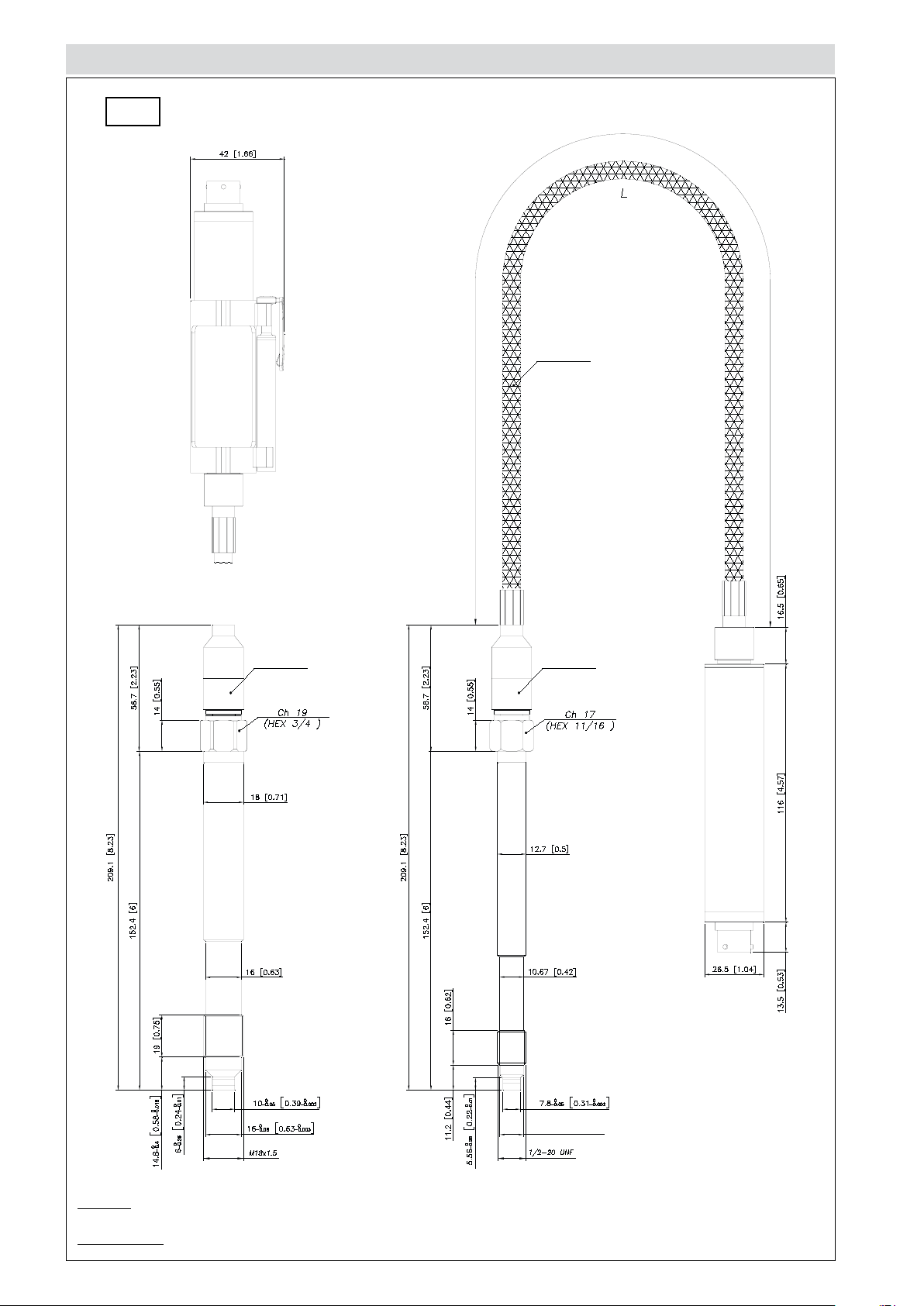
MECHANICAL DIMENSIONS
IX0
NOTE : dimensions refer to rigid stem length option “4” (153 mm – 6”)
WARNING : For installation use a maximum tightening torque of 40 Nm (355 in-lb)
10.9
+0
-0.05
[0.43
+0
-0.002
]
Page 3

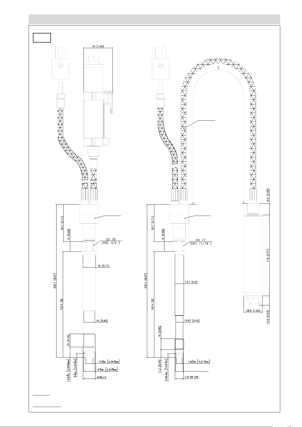
MECHANICAL DIMENSIONS
Max Temp.
220° C (428° F)
Max Temp.
220° C (428° F)
Max Temp.
220° C (428° F)
Max Temp.
220° C (428° F)
10.9
+0
-0.05
[0.43
+0
-0.002]
IX1M
NOTE : dimensions refer to rigid stem length option “4” (153 mm – 6”)
WARNING : For installation use a maximum tightening torque of 40 Nm (355 in-lb)
Page 4
MECHANICAL DIMENSIONS
Max Temp.
220° C (428° F)
Max Temp.
220° C (428° F)
Max Temp.
220° C (428° F)
10.9
+0
-0.05
[0.43
+0
-0.002]
IX1S
NOTE : dimensions refer to rigid stem length option “4” (153 mm – 6”)
WARNING : For installation use a maximum tightening torque of 40 Nm (355 in-lb)
Page 5
MECHANICAL DIMENSIONS
Max Temp.
220° C (428° F)
Max Temp.
230° C (446° F)
Max Temp.
230° C (446° F)
10.9
+0
-0.05
[0.43
+0
-0.002
]
IX2
NOTE : dimensions refer to rigid stem length option “4” (153 mm – 6”)
WARNING : For installation use a maximum tightening torque of 40 Nm (355 in-lb)
Page 6
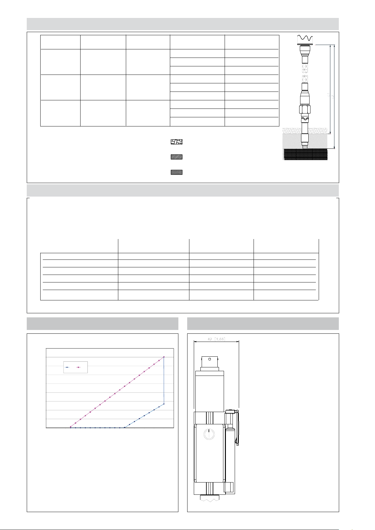
ELECTRICAL CHARACTERISTICS AND TEMPERATURE CLASSES
900
32
R (
Ω
Ω
Ω
Ω)
MODEL (*) LEVEL (*) LEVEL TEMPERATURE ROOM
L2 L1 CLASSES TEMPERATURE
IX0 > 165mm > 125mm T6/T85 -20...+60°C
T5/T100 -20...+75°C
T4/T135 -20...+85°C
IX1 > 665mm > 625mm T6/T85 -20...+60°C
T5/T100 -20...+75°C
T4/T135 -20...+85°C
IX2 > 665mm > 625mm T6/T85 -20...+60°C
T5/T100 -20...+75°C
T4/T135 -20...+85°C
(*) with the level (L) in fig. 1, the table sets the minimum
distance that the electrical circuit has to maintain from
thermal isolating material with adequate
thickness for the process temperature
the block at high temperature.
pressure transmitter housing block
Fig. 1
fluid at temperature (350°C)
INTRINSIC SAFETY CHARACTERISTICS
Main intrinsic safety characteristics
Transmitter designed and produced in compliance with Directive ATEX and according to European standards:
Protection:
II 1GD, Ex ia IIC T6, T5, T4 Ga, ambient temperature -20...+60°C / +75°C / +85°C;
Ex ia IIIC T85°C, T100°C, T135°C Da IP65, ambient temperature -20...+60°C / +75°C / +85°C
II 1GD, EX ia IIC T6 Ga
Ex ia IIIC T85°C Da IP65
Maximum voltage Ui 30Vdc 30Vdc 30Vdc
Maximum current Ii 100mA 100mA 100mA
Maximum power Pi 0.75W 0.75W 0.75W
Maximum inductance (*) Li 1.1 mH 1.1 mH 1.1 mH
Maximum capacity (*) Ci 46nF 46nF 46nF
Ambient temperature -20...+60°C -20...+75°C -20...+85°C
(*) includes inductance levels and capacity of a cable: (typical L 1mH/m and typical C 100 pF/m) with maximum length 15mt.
II 1GD, EX ia IIC T5 Ga
Ex ia IIIC T100°C Da IP65
II 1GD, EX ia IIC T4 Ga
Ex ia IIIC T135°C Da IP65
AUTOZERO FUNCTIONLOAD DIAGRAM
800
700
600
500
400
300
200
100
0
6810 12 14 16 18 20 22 24 26 28 30
The diagram shows the optimum ratio between load and
power supply for transmitters with 4…20mA output.
For correct function, use a combination of load resi-
stance and voltage that falls within the shaded area.
R min R max
Vcc (V)
The Autozero function is activa-
ted through a magnetic contact
(external magnet supplied with the
sensor).
For the external Autozero version
short-circuit the correct pin.
See the manual for a complete
Autozero function explanation.
Page 7
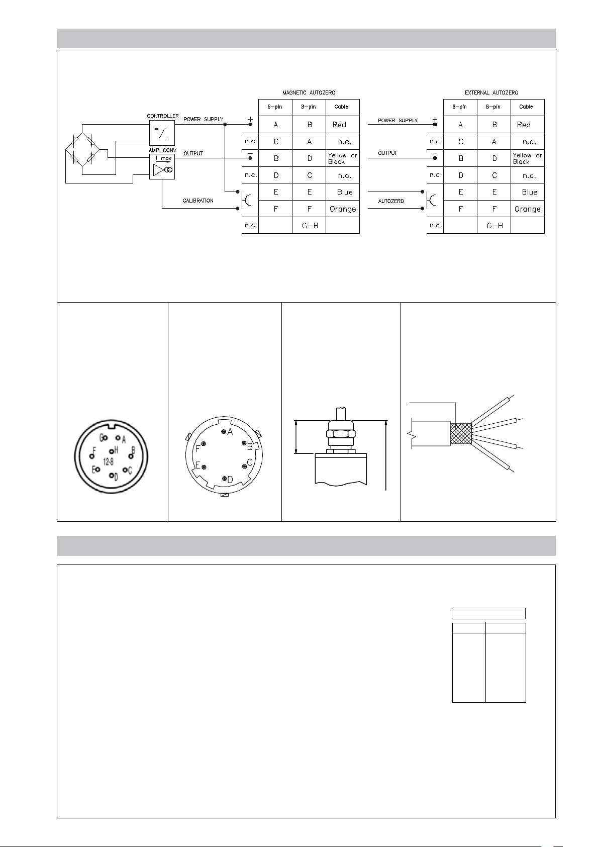
ELECTRICAL CONNECTIONS
17
[4.134]
CURRENT OUTPUT (4...20mA, 2-wires)
The cable shield is tied to connector via cable clamp
8 pin connector
PC02E-12-8P
Bendix
6 pin connector
VPT07RA10-6PT2
(PT02A-10-6P)
4 pole cable
[0.668]
ACCESSORIES
Connectors
6-pin female connector (IP65 protection degree) CON300
8-pin female connector CON307
Extension cables
6-pin connector with 3m (10ft) cable PCAV221
6-pin connector with 4m (13ft) cable PCAV104
6-pin connector with 5m (16ft) cable PCAV105
6-pin connector with 10m (33ft) cable PCAV106
Accessories
Mounting bracket SF18
Dummy plug for 1/2-20UNF SC12
Dummy plug for M18x1.5 SC18
Drill kit for 1/2-20UNF KF12
Drill kit for M18x1.5 KF18
Cleaning kit for 1/2-20UNF CT12
Cleaning kit for M18x1.5 CT18
Fixing pen clip PKIT 379
Autozero pen PKIT 378
L = 105
4 pole cable
Shield
Shielded cable 4x0.25 - 2m.
Protection IP65
Cable color code
Conn. Wire
A Red
B Black
C White
D Green
E Blue
F Orange
Blue
Orange
Red
Yellow
or Black
Page 8
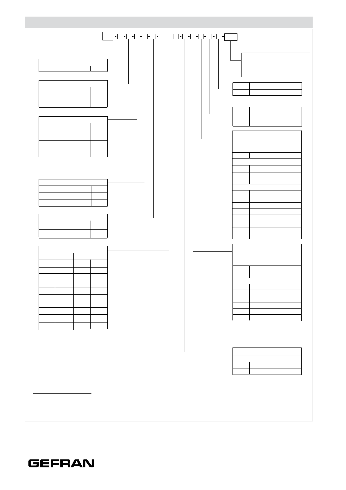
ORDER CODE
OUTPUT SIGNAL
4...20mA
Rigid rod
Rigid + flexible stem
With thermocouple
MECHANICS
Single fixed
Modular fixed
SingleAS
Modular
* Not available for
IX0 and IX2 version
CONNECTOR
6 pin 6
8 pin
Cable output F
ACCURACY CLASS
0.25% FSO H
0.5% FSO M
X
VERSION
0
1
2
B *
M *
8
I
000
000= Special executions of the
standard version or of custom
versions may be requested.
External Autozero
E
Magnetic Autozero-
Ex ia T4 Ga/Ex ia T135°C Da
4
Ex ia T5 Ga/Ex ia T100°C Da
5
Ex ia T6 Ga/Ex ia T85°C Da
6
FLEXIBLE STEM LENGTH (L)
(mm / inches)
Standard (IX0)
0
none
Standard (IX1, IX2)
D
457mm
610mmE
760mmF
Available on request
A
76mm
B
152mm
C
300mm
G
914mm
H
1067mm
I
1220mm
J
1372mm
K
1520mm
18”
24”
30”
3” 1)
6” 1)
12” 1)
36”
42”
48”
54”
60”
MEASUREMENT RANGE
bar
20* B02D
35 B35U
50 B05D
70 B07D
100 B01C
200 B02C
350 B35D
500 B05C
B07C
700
1000 B01M
* 10 bar (B01D) or 150psi (P15D)
for version M18x1,5
psi
300 P03C
500 P05C
750 P75D
1000 P01M
1500 P15C
3000 P03M
5000 P05M
7500 P75C
10000 P10M
15000 P15M
RIGID STEM LENGTH
(mm / inches)
Standard (IX0, IX1, IX2)
4
153mm
318mm5
Available on request
1
38mm
2
50mm
3
76mm
6
350mm
400mm
7
8
456mm
1) in IX1 and IX2 versions, to use
rigid stem and flexible with a total
length ≥665mm
THREADING
Standard
1
1/2 - 20 UNF
M18 x 1.54
6”
12.5”
1.5” 1)
2” 1)
3” 1)
14”
16”
18”
Example
IX1-S-6-M-B07C-1-4-D-4
Melt pressure transducer without filling, 4-20mA output, 6-pin connector, 1/2-20 UNF threading, 700 bar pressure range, 0.5%
accuracy, 153 mm (6”) rigid stem, 457 mm (18”) flexible stem; temperature class T4
Electrical installation requirements and Conformity certificate are available on our web site: www.gefran.com
GEFRAN reserves the right to make any kind of design or functional modification at any moment without prior notice
DTS_IX_11-2016_ENG
 Loading...