

Page 1
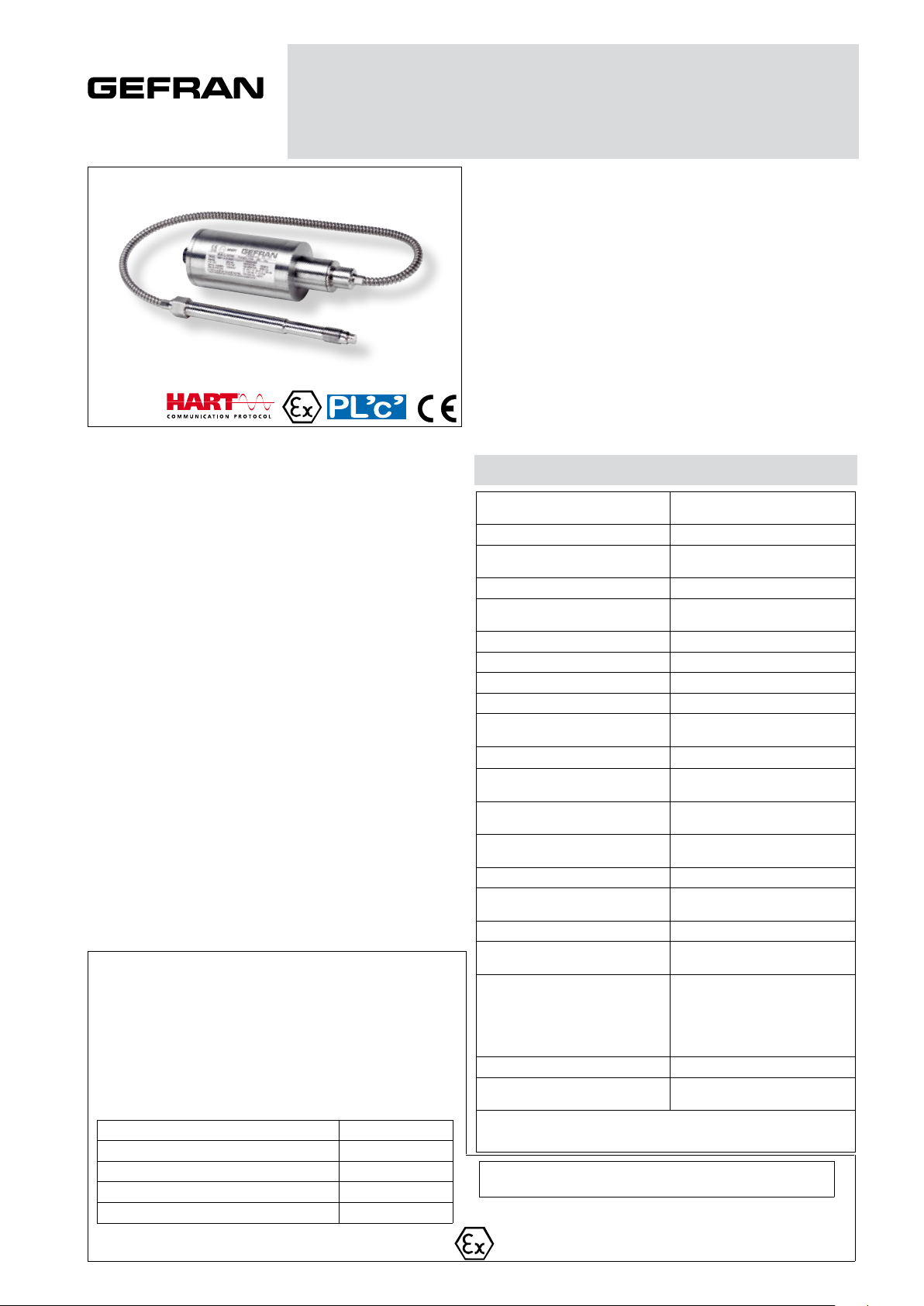
SMART HART MERCURY FILLED MELT PRESSURE TRANSMITTERS
FOR APPLICATIONS IN POTENTIALLY EXPLOSIVE ATMOSPHERES
HMX SERIES - CURRENT OUTPUT AND PERFORMANCE LEVEL ‘c’
4...20mA Output
The HMX series of Gefran are pressure transmitters with
HART communication protocol for using in high temperature environment with explosive atmosphere presence.
The main characteristic of this series is the capability to
read temperature of the media up to 400°C.
The constructive principle is based on the hydraulic trasmission of the pressure.
The fluid-filled system assures the temperature stability.
The physical measure is transformed in a electrical measure by means of strain-gauge technology.
MAIN FEATURES
• Pressure ranges from: 0-17 a 0-2000 bar/0-250 a 0-30000 psi
• Extensimetric measurement principle with Wheatstone bridge
• Accuracy: < ±0.25% FSO (H); < ±0.5% FSO (M)
• Calibration signal 80% FSO internally generated
• Completely interchangeable with all existing products
• Protection level: IP65 (6-pin connector)
• 1/2-20UNF, M18x1.5 standard threads; other types available
on request
• Standard diaphragm is 15-5 PH stainless steel with GTP+
coating
• 17-7 PH corrugated stainless steel diaphragm with GTP+ coating
for ranges below 100 bar-1500 psi
• Other diaphragm types available on request
HMX0 The rigid rod configuration provides fast and easy
installation.
HMX1 The flexible rod configuration is suitable for applications
demanding greater thermal isolation and where installa tion would otherwise be difficult.
HMX2 This configuration lets you measure process pressure
and temperature at the same point with a single installa tion.
HMX3 The configuration with exposed tip is ideal for applica tions in limited space.
Main intrinsic safety characteristics
Transmitter designed and produced in compliance with Directive
ATEX 2014/34/EU and according to European standards.
Protection mode: group II, category 1G, 1D
GAS protection mode: Ex ia IIC T6, T5, T4 Ga (Ambient Temp.:
-20°C...+60°C / +75°C / +85°C)
DUST protection mode: Ex ia IIIC T85°C, T100°C, T135°C Da
IP65 (Ambient Temp.: -20°C...+60°C / +75°C / +85°C)
Maximum voltage 30 V
Maximum current 100 mA
Maximum power 0,75 W
Maximum inductance (*)
Maximum capacity (*) 10 nF
17 mH
TECHNICAL SPECIFICATIONS
Accuracy (1)
Resolution 16 bit
Measurement range
Rangeability 3:1
Maximum overpressure (without
degrading performances)
Measurement principle Extensimetric
Power supply 13...30Vdc
Maximum current absorption 23mA
Output signal Full Scale (FSO) 20mA
Zero balance (tollerance ± 0.25%
FSO)
Calibration signal 80% FSO
Power supply polarity reverse
protection
Compensated temperature range
housing
Operating temperature range
housing
Storage temperature range housing -40...+125°C
Thermal drift in compensated range:
Zero / Calibration / Sensibility
Diaphragm maximum temperature 400°C / 750°F
Zero drift due to change in process
temperature (zero)
Standard material in contact with
process medium
Thermocouple (model HMX2) STD: type “J” (isolated junction)
Protection degree
(with 6-pole female connector)
FSO = Full scale output
(1) BFSL method (Best Fit Straight Line): includes combined effects of Non-Linearity,
Hysteresis and Repeatability
(*) includes inductance levels and capacity of a cable:
(typical L 1microH/m and typical C 100pF/m) with maximum length 15m.
The Melt pressure transmitters must be connected to other equipment
(galvanic isolation barriers) with individual ATEX certification such as
[Ex ia Ga] IIC. The thermocouple circuit must be powered by means of
H <±0.25%FSO (100...2000 bar)
M <±0.5%FSO (17...2000 bar)
0..17 to 0..2000bar
0..250 to 0..30000psi
2 x FS
1.5 x FS above 1000bar/15000psi
4mA
YES
0...+85°C
-30...+85°C
< 0.02% FSO/°C
< 0.02 bar/°C
Diaphragm:
• 15-5 PH with GTP+ coating
• 17-7 PH corrugated diaphragm with
GTP+ coating for ranges <100bar
(1500psi)
Stem: • 17-4 PH
IP65
Page 2
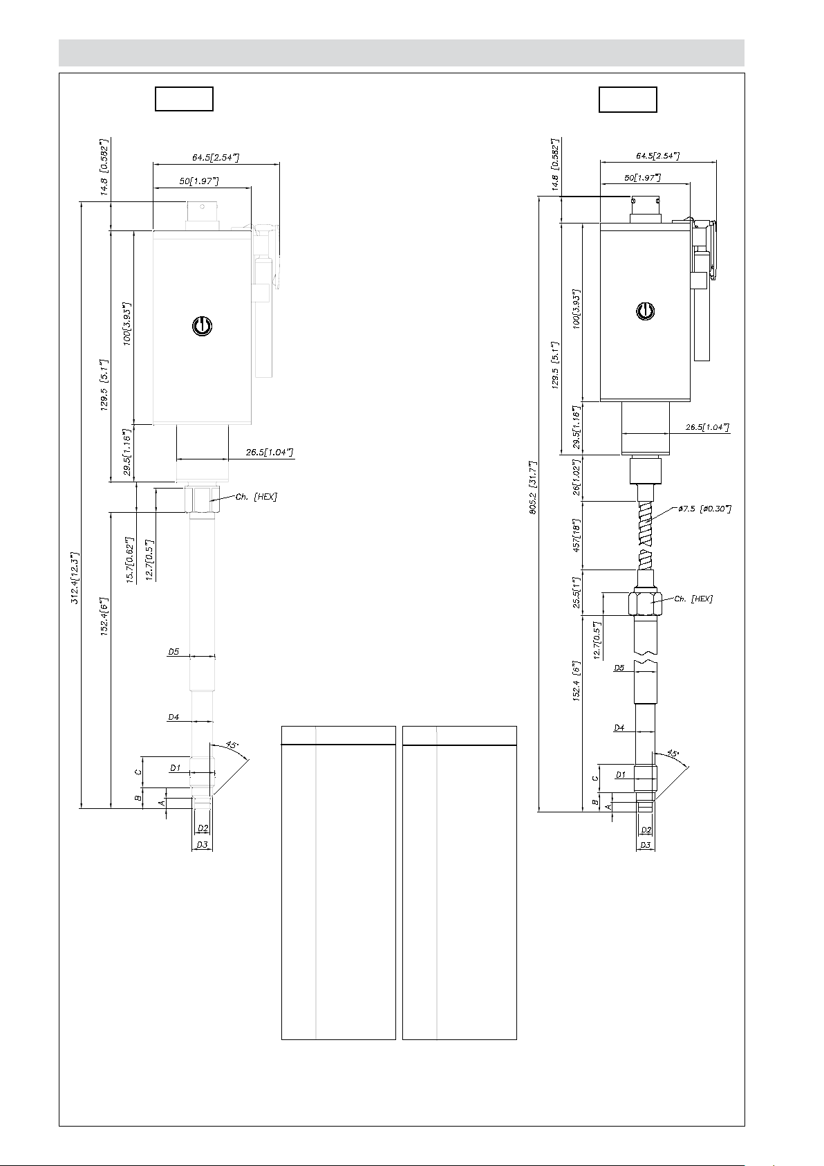
MECHANICAL DIMENSIONS
HMX1HMX0
D1
D2
D3
D4
D5
A
B
C
Ch
[Hex]
1/2 - 20UNF
ø7.8 -0.05
[ ø0.31” -0.002 ]
ø10.5 -0.025
[ ø0.41” -0.001 ]
ø10.67
[ ø0.42” ]
ø12.7
[ ø0.5” ]
5.56 -0.26
[ 0.22” -0.01 ]
11.2
[ 0.44” ]
15.74
[ 0.62” ]
16
[ 5/8” ]
D1
D2
D3
D4
D5
A
B
C
Ch
[Hex]
M18x1.5
ø10 -0.05
[ ø0.394” -0.002 ]
ø16 -0.08
[ ø0.63” -0.003 ]
ø16 -0.4
[ ø0.63” -0.016 ]
ø18
[ ø0.71” ]
6 -0.26
[ 0.24” -0.01 ]
14.8 -0.4
[ 0.58” -0.016 ]
19
[ 0.75” ]
19
[ 3/4” ]
NOTE: dimensions refer to rigid stem length option “4” (153 mm– 6”)
WARNING: For installation use a maximum tightening torque of 56 Nm (500 in-lb)
Page 3

MECHANICAL DIMENSIONS
HMX2
HMX3
D1
D2
D3
D4
D5
A
B
C
Ch
[Hex]
1/2 - 20UNF
ø7.8 -0.05
[ ø0.31” -0.002 ]
ø10.5 -0.025
[ ø0.41” -0.001 ]
ø10.67
[ ø0.42” ]
ø12.7
[ ø0.5” ]
5.56 -0.26
[ 0.22” -0.01 ]
11.2
[ 0.44” ]
15.74
[ 0.62” ]
16
[ 5/8” ]
D1
D2
D3
D4
D5
A
B
C
Ch
[Hex]
M18x1.5
ø10 -0.05
[ ø0.394” -0.002 ]
ø16 -0.08
[ ø0.63” -0.003 ]
ø16 -0.4
[ ø0.63” -0.016 ]
ø18
[ ø0.71” ]
6 -0.26
[ 0.24” -0.01 ]
14.8 -0.4
[ 0.58” -0.016 ]
19
[ 0.75” ]
19
[ 3/4” ]
NOTE: dimensions refer to rigid stem length option “4” (153 mm– 6”)
WARNING: For installation use a maximum tightening torque of 56 Nm (500 in-lb)
Page 4

SELF DIAGNOSTICS (ONLY FOR PL’C’ VERSIONS)
0
100
200
300
400
500
600
700
800
900
10 12 14 16 18 20 22 24 26 28 30 32
R ( Ω)
Vcc (V)
WORKING AREA
Below the conditions detected by the sensor self-diagnostics:
· Cut cable / device non connected / broken power supply, output ≤ 3.6mA
· Pin detachment output ≤ 3.6mA
· Broken primary element ≥21mA
· Pressure above 200% of the span, output ≥21mA
· Voltage monitor in case of overvoltage/undervoltage/voltage variation in the electronics, output ≤ 3.6mA (*)
· Program sequence error, output ≤ 3.6mA (*)
· Overtemperature on the electronics, output ≤ 3.6mA (*)
· Error on the primary element output or on the first amplification stage, output ≥ 21mA
(*) In such conditions the Alarm Type can be programmed via HART at ≥ 21 mA.
NAMUR COMPLIANCE (ONLY FOR PL’C’ VERSIONS)
The sensors are tested according to Namur NE21 recommendations. The same compatibility is valid for the NE43 Namur
recommendation with the following sensor behaviour in case of breakdown:
· Cut cable: breakdown information as the signal is ≤ 3.6mA
· Device not connected: breakdown information as the signal is ≤ 3.6mA
· Broken power-supply: breakdown information as the signal is ≤ 3.6mA
or in case of performance problems:
· Broken primary element ≥ 21mA
· Pressure above 200% of the span, output ≥21 mA
· Others ≤ 3.6mA(*)
(*) In such a condition the Alarm Type can be programmed via HART at ≥ 21 mA.
Note: in all the remaining situations, the output signal is always included between 3.8 and 20.5mA.
Recommendation: the error level set by the customer (e.g. maximum pressure value) has to be inside the
nominal range.
The diagram shows the optimum ratio between load and
power supply for transmitters with 4…20mA output.
For correct function, use a combination of load resistance and voltage that falls within the two lines in the graph
above.
AUTOZERO FUNCTIONLOAD DIAGRAM
The Autozero function is activated through a magnetic contact (external magnet supplied with the sensor).
The Autozero function can be activated through HART command as well.
See the manual for a complete Autozero function explanation.
Page 5

ELECTRICAL CONNECTIONS
CURRENT OUTPUT
The cable shield is tied to both sides, i.e. to the sensor connector and to the controller
6 pin Connector
VPT07RA10-6PT2
(PT02A-10-6P)
8 pin Connector
(PC02E-12-8P) Bendix
Cable outlet (1/2 14-NPT)
Current output
L = 1 m
ACCESSORIES
Connectors
6-pin female connector (IP65 protection degree) CON300
8-pin female connector CON307
Accessories
Mounting bracket SF18
Dummy plug for 1/2-20UNF SC12
Dummy plug for M18x1.5 SC18
Drill kit for 1/2-20UNF KF12
Drill kit for M18x1.5 KF18
Cleaning kit for 1/2-20UNF CT12
Cleaning kit for M18x1.5 CT18
Fixing pen clip PKIT1032
Autozero pen PKIT378
Extension cables
6-pin connector with 3mt Atex cable PCAV221
6-pin connector with 4mt Atex cable PCAV104
6-pin connector with 5mt Atex cable PCAV105
6-pin connector with 10mt Atex cable PCAV106
Thermocouples for model HMX2
Type “J” (for rigid rod 153mm - 6”) TTER 601
Cable color
code
Conn. Wire
A-2 Red
B-4 Black
C-1 White
D-6 Green
E-7 Blue
F-3 Orange
5 Grey
8 Pink
Page 6

ORDER CODE
HM
0000
X 000 X 0
000= Special executions
OUTPUT SIGNAL
4...20mA X
VERSION
Rigid rod 0
Rigid + flexible rod 1
T4 Ex ia IIC T4 Ga (Tambient:
4
-20°C...+85°C)/Ex ia IIIC T135°C Da IP65
T5 Ex ia IIC T5 Ga (Tambient:
5
-20°C...+75°C)/Ex ia IIIC T100°C Da IP65
T6 Ex ia IIC T6 Ga (Tambient:
6
-20°C...+60°C)/Ex ia IIIC T85°C Da IP65
With thermocouple 2
Exposed capillary 3
CONNECTOR
6 pin 6
8 pin 8
NPT Cable N
ACCURACY CLASS
0.25% FSO (ranges ≥ 100 bar/1500 psi)
0.5% FSO M
MEASUREMENT RANGE
bar psi
17 B17U 250 P25D
35 B35U 500 P05C
50 B05D 750 P75D
70 B07D 1000 P01M
100 B01C 1500 P15C
200 B02C 3000 P03M
350 B35D 5000 P05M
500 B05C 7500 P75C
700 B07C 10000 P10M
1000 B01M 15000 P15M
1400 B14C 20000 P20M
2000 B02M 30000 P30M
H
E External Autozero (*)
0 Magnetic Autozero
(*) as an alternative to the CAL function
P Performance Level=’c’
0 Standard 4...20mA
FLEXIBLE ROD LENGTH (mm/inches)
Standard (HMX0)
0 none
Standard (HMX1, HMX2)
D 457mm 18”
E 610mm 24”
F 760mm 30”
Standard (HMX3)
711mm 28”
L
Available on request
A 76mm 3”
B 152mm 6”
C 300mm 12”
G 914mm 36”
H 1067mm 42”
I 1220mm 48”
J 1372mm 54”
K 1520mm 60”
THREADING
Standard
1/2 - 20 UNF 1
M18 x 1.5 4
Available on request
M10 x 1 (range ≥200bar / 3000psi) 2
M14 x 1.5 3
Example
HMX1-6-M-B07C-1-4-D-0-0-4
Melt pressure transmitter, 4...20mA output with HART protocol, 6-pin connector,
1/2-20 UNF threading, 700 bar pressure range, 0.5% accuracy, 153 mm (6”) rigid
rod, 457 mm (18”) flexible rod, temperature class T4 (-20°C...+85°C).
Sensors are manufactured in compliance with:
- EMC compatibility directive
RIGID ROD LENGTH (mm/inches)
Standard (HMX0, HMX1, HMX2)
4 153mm 6”
5 318mm 12.5”
Standard (HMX3)
0 none
Available on request
1 38mm 1,5”
2 50mm 2”
3 76mm 3”
6 350mm 14”
7 400mm 16”
8 456mm 18”
- ATEX directive
- machinery directive
Product designed and available in compliance with Directive 2011/65/EU (RoHS II) only for large-scale stationary installation or
industrial tools, or for B-to-B laboratory equipments for R&D purposes.
Electrical installation requirements and conformity certificate are available on our web site: www.gefran.com
GEFRAN spa reserves the right to make any kind of design or functional modification at any moment without prior notice.
DTS_HMX_07-2017_ENG
 Loading...