

Page 1
Main applications
• Thermoforming
• Plastic extrusion lines
• Industrial ovens and
furnaces
• Heat treatments
• Control applications with
high switching speed
• Mold heating/cooling
control units
• Refrigeration
• Air conditioning
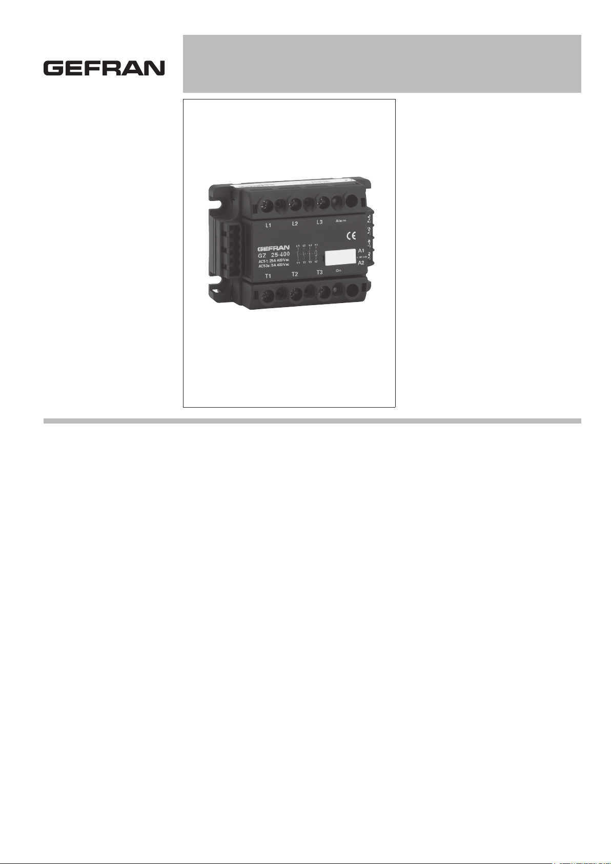
GZ 10 / 25 / 40 / 55
THREE-PHASE SOLID STATE RELAY WITH LOGIC CONTROL Vdc / Vac
Main features
• Control input from VDC/VAC logic
signal
• 3-phase alternating current solid state
relay
• Zero crossing switching
• 3-phase nominal current
3x10/25/40/55A
• Nominal voltage up to 600VCArms
• Integrated SCR thermal protection
with LED signal
• Optional alarm output (for interrupted
load diagnostics or for SCR overtem perature)
• Optoinsulation (input/output)
4000Vrms
• Integrated overvoltage suppressor
• Non-repetitive voltage up to 1200Vp
• In Conformity with EN60947-4-3 and
UL508
PROFILE
3-phase “zero crossing” solid state relay
for control of resistive and inductive loads.
Integrated device designed for industrial
applications demanding control of high
power levels and frequent switching,
with loads up to 3 x 55A (AC51) at
400/480/600Vac.
Control is logic type (Vdc or Vac), signaled by LEDs. Each phase is controlled by
means of semiconductors.
The constructive elements, special production process, and new, sturdy case,
provide excellent reliability and continuity
of service.
All versions are protected against overvoltages and against junction overtemperature, with signal LEDs and (optional) solid
state alarm output.
An optional alarm output is available for
interrupted load diagnostics .
The device is supplied complete with
covers to protect against direct contacts
(covers are removable for wiring).
Accessories available: heatsink, thermostats, fans, fuses and fuse holders.
WARNING: The GZ models must be
used in conjunction with an appropriate
heatsink (Accessory).
Installation must precisely observe the
warnings contained in the installation
notes.
TECHNICAL DATA
General features
Category of use:
AC51, AC53a
Nominal voltage (Ue):
400Vac (max. range 24...440Vac) (TRIAC)
480Vac (max. range 24..530Vac) (SCR)
600Vac (max. range 24..660Vac) (SCR)
Nominal frequency: 50/60Hz
Isolation nominal voltage (Ui): 600Vac
Peak voltage:
<800Vp for models with Ue=400Vac
<1200Vp for models with Ue=480Vac,
Ue=600Vac
Uninterrupted nominal service.
Critical dV/dt OFF-state:
500V/µs for models with Ue=400Vac
1000V/µs for models with Ue=480Vac,
Ue=600Vac
Switching voltage for zero: < 20V
Activation time: ≤1/2 cycle
Deactivation time: ≤1/2 cycle
Potential drop at rated current:≤ 1,4Vrms
IP20 protection
Weight: 300g
Page 2
Control inputs
I
R
- DC INPUT (Type “D”):
Voltage of command circuit (Uc): 5..32Vdc
Activation voltage: >4.5Vdc
Deactivation voltage:<3Vdc
Max. input: 18mA@5Vdc- 22mA@32Vdc
Max. reverse voltage: 36Vdc
- AC INPUT (Type “A”):
Control voltage: 20...260VAC/VDC
Activation voltage: > 15VAC /VDC
Deactivation voltage: < 6VAC/VDC
Current draw:
<= 8 mAAC/DC@260VAC/VDC
Additional fuse (3A max) shall be installed on the control input circuit.
Outputs
GZ 10/...
Nominal current (Imax):
AC51: 3x10 A
AC53a: 3x2 A
GZ 25/...
Nominal current (Imax):
AC51: 3x25 A
AC53a: 3x5 A
GZ 40/...
Nominal current (Imax):
AC51: 3x40 A
AC53a: 3x8 A
GZ 55/...
Nominal current (Imax):
AC51: 3x55 A
AC53a: 3x15 A
Thermal features
GZ 10,25
Junction temperature: ≤125°C
Rth junction/case =1.5 K/W
GZ 40
Junction temperature: ≤125°C
Rth junction/case =1 K/W
GZ 55
Junction temperature: ≤125°C
Rth junction/case =0.6 K/W
Insulation
Nominal insulation voltage input/output:
2.5KV ac for models with Ue=400Vac
4KV ac for models with Ue=480Vac,
Ue=600Vac
Nominal impulse withstand voltage
(Uimp): 2500Vac
Solid Sate Relay Dissipated Power
Calculation
Three-phase relay
Pd=3x1,4*IRMS [W]
IRMS= three-phase load current
Heatsink Thermal Resistance
Calculation
Rth=(90°C-T.amb.max)/Pd
Pd = dissipated power
T.amb.max=max air temperature inside
the electrical cabinet.
Use a heatsink with thermal resistance
inferior to the calculated one (Rth)
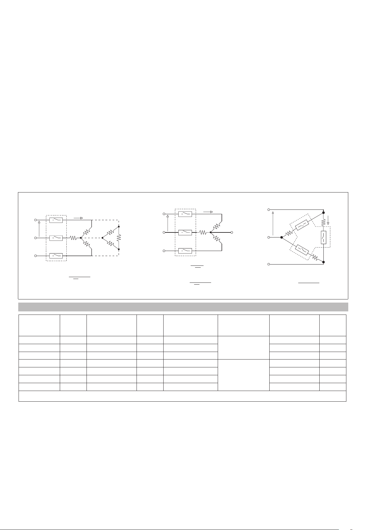
Three-phase Star or Triangle closed control
R
L1
V
S
L2
T
L3
I
T1
R
R
T2
R
T3
R
R
R
V nominal = V
P
I nominal =
V
+10%
3 • V
Three-phase Star control with neutral
R
S
T
V nominal =
I nominal =
L1
T1
V
L2
T2
L3
T3
R
R
R
V
V
3
P
V
+10%
3 • V
Three-phase Triangle open control
L1
V
S
T
T1
R
L2
R
T3
L3
T2
R
V nominal = V
P
I nominal =
+10%
3 • V
TECHNICAL DATA OF THE MAIN CIRCUIT
Model Imax
[Arms]
GZ 10/400 3x10 1.78 3x10 1.19
GZ 25/400 3x25 0.57 3x25 0.38 250 450
GZ 25/480 3x25 0.57 3x25 0.38 400 645
GZ 40/480 3x40 0.36 3x40 0.24
GZ 55/480 3x55 0.19 3x55 0.16 1150 6600
GZ 40/600 3x40 0.36 3x40 0.24 600 1010
GZ 55/600 3x55 0.19 3x55 0.16 1150 6600
(*) Ie = Nominal current (Standard CEI EN 60947-4-3)
Rth,heatsink
@Ta=40°C
[K/W]
Ie (*)
[Arms]
Rth,heatsink
@Ta=40°C
[K/W]
Dimension
heatsink
(accessories)
100x127x80
100x127x100
(with fan)
Non-repetitive
overcurrent
t=20ms [A]
120 100
600 1010
I
I2t
[A2s]
Ambient conditions
• Working temperature: -20°C...80°C
• Max. relative humidity: 50% to 40°C
• Max. installation altitude: 2000 slm
• Pollution level : 2
• Storage temperature: -20...85°C
• Class: A (industrial device)
• Suitable for use in pollution degree 2
environmental
Thermal protection
Junction temperature is constantly monitored inside the device.
If the maximum temperature limit is
exceeded (T=110°C), current to the load
is interrupted and the yellow signal LED
lights up.
Options
Option 1
(Thermal protection alarm output)
The alarm output option activates closing
of an isolated contact (max 32VAC/VDC,
150mA, conducting resistance <=15 ohm)
when it detects the following condition:
control signal active but SCR / heatsink
is in overtemperature (GZ thermal protection)
Option 2
(Thermal protection alarm output and
interrupted load).
Only for GZ with Type “A” input
The alarm output option activates closing
of an isolated contact (max 32VAC/VDC,
150mA, conducting resistance <=15 ohm)
when it detects the following conditions:
- Control signal active but no current in at
least one three-phase branch (interrupted
load)
- Control signal active but no power line
voltage (no line)
- Control signal active but SCR / heatsink
Page 3
L1 L2 L3
T1 T2 T3
AC51: 25A 400Vac
AC53a: 5A 50/60Hz
GZ 25/400-0-1
On
L1 L2 L3 A1+
T1 T2 T3 A2-
Alarm
B1
B2
A1
A2
5..32
Vdc
5,2mm
73mm
47,5mm
103,5mm
92mm
is in overtemperature (GZ thermal protection).
Maximum delay in tripping of load interrupt
alarm < 400ms.
Maximum length of wires between GS and
load for correct operation of load diagnostics < 25m
Installation notes
Use the high speed fuses specified in the
catalog according to the connection example provided.
Applications with solid state power units
must also include an automatic safety
switch to cut out the load power line.
Protect the solid state relay by using an
appropriate heat sink (accessory).
The heat sink must be sized according to
room temperature and load current (see
the technical documentation).
Procedure for mounting on heat sink:
The module-heat sink contact surface
must have a maximum planarity error
of 0.05mm. and maximum roughness of
0.02mm.
The fastening holes on the heat sink must
be threaded and countersunk.
Spread 4 gram of thermoconductive silicone (we recommend DOW CORNING 340
HeatSink) on the dissipative metal surface
of the module.
The surfaces must be clean and there
must be no impurities in the thermoconductive paste.
Use 4 M4x10 or M5x10 screws with flexible
washer for attachment.
Alternately tighten the fastening screws
until reaching a torque of 0.60Nm.
Wait 30 minutes for any excess paste to
drain.
Alternately tighten the four fastening
screws until reaching a torque of 1.2 Nm
for the M4 screws and 1.5 Nm for the M5
screws.
It is advisable to make random checks of
correct installation by disassembling the
module and checking that there are no air
bubbles under the copper plate
Install the units cantilevered to the panel so
that air can flow vertically over the heatsink
without obstructions.
• Maximum surrounding air temperature
40°C (for UL).
• Open type equipment
Limits of use
• dissipation of thermal power of device
with restrictions on temperature of installation site.
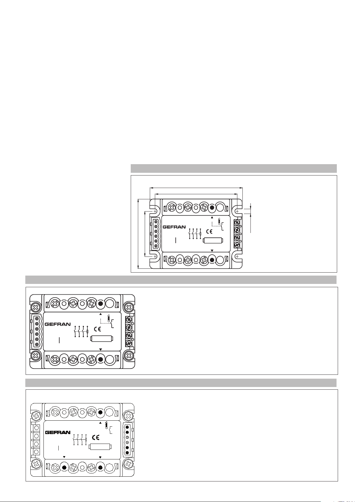
DIMENSIONS
• requires exchange with outside air or an
air conditioner to transfer dissipated power
outside the panel.
• max. voltage limits and derivative of transients in line, for which the solid state unit
has internal protection devices.
• presence of dispersion current < 10mA
(max. value with rated voltage and junction
temperature of 125°C).
Depth:
- Model GZ-xx/xx-D-x : 44 mm
- Model GZ-xx/xx-A-x : 52 mm
FACEPLATE DESCRIPTION GZ with DC control (Models GZ-xx/xx-D-x
L1 : Phase 1 input
L2 : Phase 2 input
L3 : Phase 3 input
L1 L2 L3
L1 L2 L3 A1+
GZ 40/600-0-1
fan:230Vac
VEN-90
AC51: 40A 600Vac
AC53a: 8A 50/60Hz
T1 T2 T3
T1 T2 T3 A2-
Alarm
On
B1
B2
A1
5..32
Vdc
A2
T1 : Phase 1 output
T2 : Phase 2 output
T3 : Phase 3 output
A1 : Control signal (+)
A2 : Control signal (-)
B1 : Alarm output (option)
B2: Alarm output (option)
Led ON: Red led signal indicator
Led Alarm: Yellow led (alarm overtemperature junction)
FACEPLATE DESCRIPTION GZ with AC control (Models GZ-xx/xx-A-x)
L1 : Phase 1 input
L2 : Phase 2 input
L3 : Phase 3 input
T1 : Phase 1 output
T2 : Phase 2 output
T3 : Phase 3 output
A1 : Control signal (AC)
A2 : Control signal (AC)
B1 : Alarm output (option)
B2: Alarm output (option)
Led ON: Red led signal indicator
Led Alarm: Yellow led (alarm overtemperature junction)
Led OUT-AL: Red Led interrupted load alarm (with option 2 only)
L1
GZ 40/600-0-1
VEN-90
AC51: 40A
AC53a: 8A
T1 T2 T3
fan:230 Vac
600Vac
50/60 Hz
Out-Al
L2 L3
A1+
L2L1 L3
A2-
T2T1 T3
Alarm
On
B1
B2
A1
20..260 Vac
A2
Page 4

CONNECTION EXAMPLES - GZ GZ with DC control (Models GZ-xx/xx-D-x)
Three-phase Triangle or Star connection (with and without neutral)
Phase L1
Phase L2
Phase L3
Neutral
Ground
F1
F2
F3
Load
1/L1
3/L2
GZ 25/60-D-1
600Vac
R
R
R
RRR
R
R
R
AC51:25A
AC53a: 5A
2/T1
50/60 Hz
4/T2
Heatsink (accessory)
135
246
5/L3
6/T3
A1+
A2-
Alarm
5-32Vdc
ON
* Only in the version with option overtemperature alarm output
CONNECTION EXAMPLES - GZ with AC control (Models GZ-xx/xx-A-x)
Phase L1
Phase L2
Phase L3
Neutral
Ground
I < 150 mA
V
< 30V
B1
B2
A1
A2
5-32 Vdc
+
-
Digital
output
(*)
Controller
* Only in the version with option alarm output
F1
F2
1/L1
3/L2
GZ 25/60-A-2
600Vac
AC51: 25A
50/60 Hz
AC53a: 5A
Out
Al
2/T1
4/T2
Heatsink (accessory)
F3
1 3
2 4 6
5/L3
5
6/T3
A1
A2
Alarm
20-260
Vac/Vdc
On
I < 1 50 mA
B1
B2
nc
nc
A1
A2
ON/OFF
Switch
V
< 30V
20........260 Vac/Vdc
Fuse 3A (max)
(* )
Page 5

TYPE OF OPERATION
ALARM OPTION – DC INPUT: FUNCTIONAL DIAGRAM:
THERMAL PROTECTION ALARM
IN DC control
________________________________________________
ON LED (red)
_______________________________________________
Alarm LED (yellow)
________________________________________________
Load Current
______________________________________________
Alarm output ON
______________________________________________
ALARM OPTION – AC INPUT: FUNCTIONAL DIAGRAM:
THERMAL PROTECTION ALARM
INTERRUPTED LOAD ALARM
IN AC control
_________________________________________________
ON LED (red)
_______________________________________________
Alarm LED (yellow)
________________________________________________
Out-Al LED (red)
________________________________________________
Load Current
______________________________________________
Alarm output ON
______________________________________________
IN AC control
_________________________________________________
ON LED (red)
_______________________________________________
Alarm LED (yellow)
________________________________________________
T_SCR > 110°C
T_SCR > 110°C
T_SCR < 110°C
T_SCR < 110°C
Out-Al LED (red)
________________________________________________
Load Current
______________________________________________
Alarm output ON
_______________________________________________
Load failure
Load restored
Page 6

TABLE OF TERMINALS AND CONDUCTORS
Model
GZ 10...55A
with DC control
GZ 10...55A
with AC control
Model
GZ 10...40A
GZ 55A
I/O control terminal
Contact area
(LxD)
screw type
6,3x9
M3
Plug connector
2/6 pins
(A1, A2, B1, B2)
Type of
pre-insulated
crimp
connector
eye / fork / tip
Stripped wire
or tip
Wire section
(*)/ tightening
torque
min. 0.35 mm
max. 2,5 mm
0,6 Nm Max
min. 0.25 mm
max. 2,5 mm
0,5 Nm Max
Contact area
screw type
2
2
2
2
(LxD)
12x12
M5
Power terminal
(L1, L2, L3, T1, T2, T3)
Type of
pre-insulated
crimp
connector
eye / fork / tip
Ground terminal (see note)
Contact area (LxD) screw type Wire section (*)/ tightening torque
min. 1 mm
2
Area: 7x12 mm
Screw: self-threading 3.9x12 DIN7981
2
Area: 12x12 mm
Screw: M5
max. 16 mm
1,5-1,8 Nm
min. 1 mm
max. 16 mm
2 - 2,5 Nm
Wire section
(*)/ tightening
torque
min. 1 mm
max. 10 mm
2
2
(tip)
min. 1 mm
max. 16 mm
2
2
(eye / fork)
1,5 - 2,2 Nm
2
2
2
2
(*) The max. sections specified refer to unipolar copper wires
isolated in PVC.
Note: For the ground terminal, you have to use an eye wire
terminal.
(LxP) = width x depth [mm]
The minimum acceptable nominal section based on the
nominal currents of the power solid state units is given
below for copper conductors isolated in PVC, under continuous operating conditions and at 40°C ambient temperature according to standards CEI 44-5, CEI 17-11, IEC 408 in
accordance with EN60204-1
Nominal current Nominal section cable on mm
10A 2,5
25A 6
40A 10
55A 16
2
Terminal covers
If an eye terminal lug is used, the terminal covers can be
removed more easily by inserting a Phillips screwdriver
(max. width 3.5 mm) into the side slots.
With the point of the screwdriver, widen the side of the
cover and raise it.
Insert the screwdriver to facilitate opening of the cover
ACCESSORIES
A wide range of accessories is available heatsink, fuses and fuse holders , current transformer, thermostats.
To choose accessories, see the section “Solid state relays - Accessories”.
Page 7

ORDER CODE
GZ
MODEL
GZ
NOMINAL CURRENT
10Aac
25Aac
25Aac (*)
40Aac 40
55Aac 55
10
25
25B
NOMINAL VOLTAGE
400Vac (only for 25A
models and only with
40
type “D” input)
480Vac 48
600Vac 60
(*) Version with high melt energy (I²t) short
circuit-proof using a specific circuit breaker.
/
- -
OPTIONS
None
0
Alarm output
1
thermal protection
Alarm output for interrupted load diagnostics
and thermal protection.
2
(Available ONLY with
type “A” input)
INPUT TYPE
5...32Vdc
D
20...260Vac/Vdc
A
Please contact GEFRAN personnel for information on availability of codes.
GEFRAN spa reserves the right to make any kind of design or functional modification at any moment without prior notice
 Loading...