

Page 1
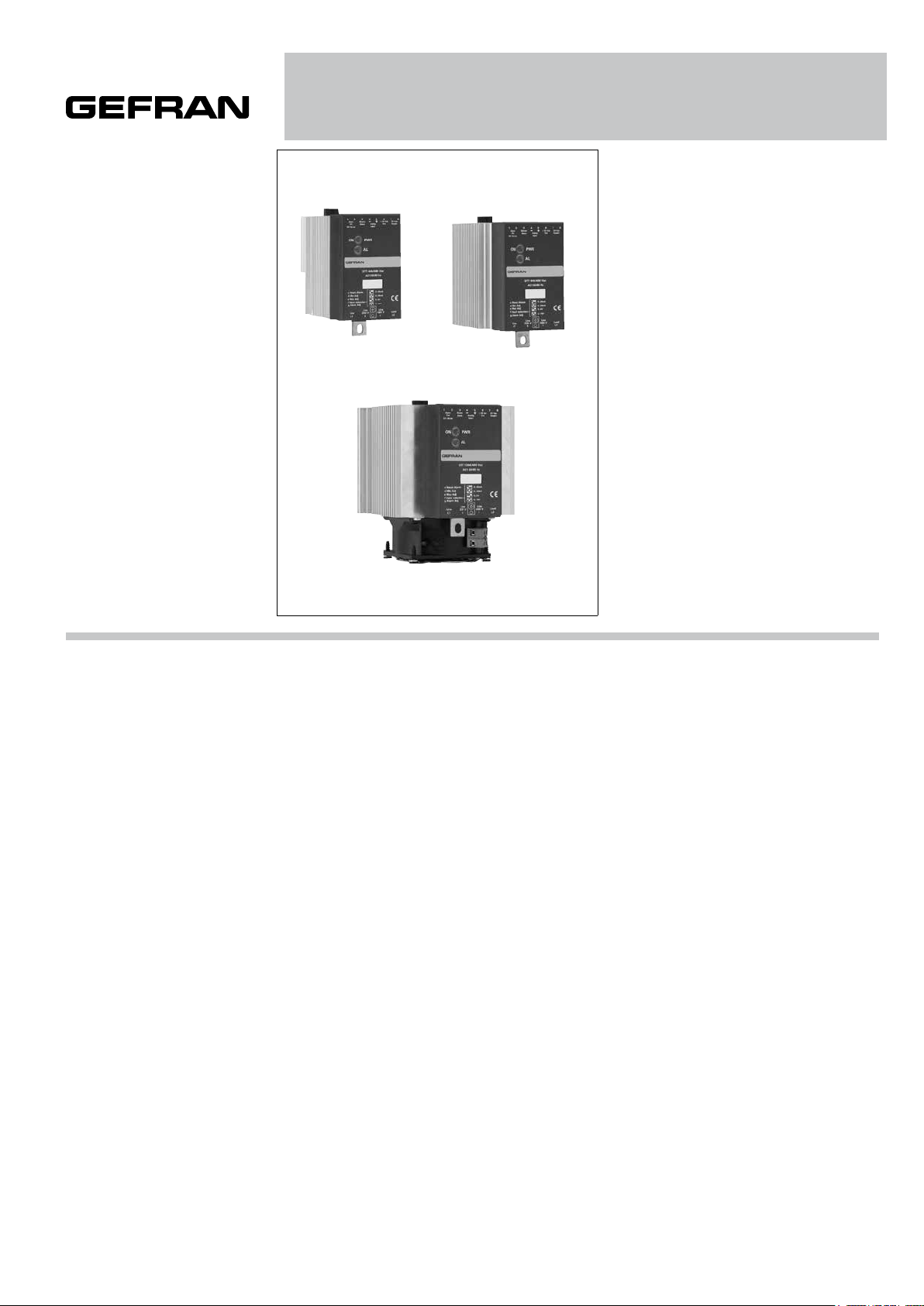
GTT 25 / 40 / 50 / 60 / 75 / 90 / 120A
POWER SOLID STATE RELAYS WITH ANALOG CONTROL
Main applications
• Plastics extrusion lines
and injection moulding
machines
• Polymerization plant for
synthetic fibre production
• Rubber moulding
machinery
• Driers for ceramics and
components for the
building industries
• Chemical and
pharmaceutical industries
• Industrial electric ovens
• Food processing plants
PROFILE
The GTT family of solid-state relays
has been designed with the aim of
providing very accurate control of the
load thanks to an analog control input, in
voltage at 0…5V; 0…10V or in current at
0…20/4…20mA or a potentiometer (from
1KΩ to 10 KΩ).
The electronic design ensures that the
cycle time for proportioning the power is
automatically optimized.
The number of cycles that the GTT
supplies to the load (wave trains) for
a given input signal is calculated to be
the minimum possible to maintain the
necessary accuracy.
This guarantees a very fast and accurate
control loop that enables the GTT, driven
by a controller or a PLC with analogue
output, to obtain very precise control.
The GTT can be used in three phase
systems, using master-slave control
architecture in which the control signal
drives only one GTT (master) and this
unit supplies the synchronized signals to
the other GTT slaves.
Two GTS modules can also be used as
slaves.
A load interrupt control option (HB)
is available without having to use an
external current transformer; alarm limit
is settable with trimmer and yellow LED
signal, with voltage-free contact, normally
open.
The GTT solid-state relay has a green
LED to indicate the presence of the
24Vac power supply and a red LED
to indicate the switching based on the
analog control input signal.
The LED signal will be continuous (off at
minimum, on at maximum) at the ends of
the scale, pulsing for intermediate values.
The units offer optional accessoires for
panel mounting, fuses and fuseholders,
current transformer, isolation
transformers
Main features
• Command input from analogue voltage
or current signal or potentiometer.
• Switching at voltage zero crossing.
• Partialization of wave train power with
dynamically optimized time cycle.
• Antiparallel double SCR
• 2 led for supply indication, “ON” state,
1 optional LED for load interrupt alarm
• 4000V isolation between input circuit
and power output
• MOV (varistor)
• Optional monitoring of interrupted load
• DIN rail mounting (standard);
Panel mounting (optional)
TECHNICAL DATA
General features
Category of use AC1
Nominal voltage
- 480Vac (max. range 24...530Vac)
Nominal frequency: 50/60Hz
Non-repetitive voltage: 1200Vp
Zero switching voltage: ≤ 20V
Voltage drop at nominal current ≤
1,4Vrms
Power factor = 1
Control inputs
Voltage: 0...5Vdc, 0...10Vdc
(impedance ≥100KΩ)
Current: 0...20mA, 4...20mA
(impedance 125Ω)
Potentiometer: from 1K to 10KΩ
(auto-fed by GTT)
Outputs
GTT 25 (SCR version)
Nominal current:
25A@40°C in continuous service
Non-repetitive overcurrent t=20 ms: 400A
I2t for blowout ≤ 645A2s
dV/dt critical with output deactivated:
1000V/µs
Page 2

GTT 40 (SCR version)
Nominal current:
40A@40°C in continuous service
Non-repetitive overcurrent t=20 ms:
600A
I2t for blowout: ≤ 1010A2s
dV/dt critical with output deactivated:
1000V/µs
GTT 50 (SCR version)
Nominal current:
50A@40°C in continuous service
Non-repetitive overcurrent t=20 ms:
1150A
I2t for blowout: ≤ 6600A2s
dV/dt critical with output deactivated:
1000V/µs
GTT 60 (SCR version)
Nominal current:
60A@40°C in continuous service
Non-repetitive overcurrent t=20 ms:
1150A
I2t for blowout: ≤ 6600A2s
dV/dt critical with output deactivated:
1000V/µs
GTT 75 (SCR version)
Nominal current:
75A@40°C in continuous service
Non-repetitive overcurrent t=20 ms:
1300A
I2t for blowout: ≤ 8000A2s
dV/dt critical with output deactivated:
1000V/µs
GTT 90 (SCR version)
Nominal current:
90A@40°C in continuous service
Non-repetitive overcurrent t=20 ms:
1500A
I2t for blowout: ≤ 11200A2s
dV/dt critical with output deactivated:
1000V/µs
GTT 120 (versione SCR)
Nominal current:
120A@40°C in continuous service
(complete with fan and standard
thermostat).
Non-repetitive overcurrent t=20 ms:
1500A
I2t for blowout: ≤ 11200A2s
dV/dt critical with output deactivated:
1000V/µs
Isolation
Rated isolation voltage input/output:
4000Vac
Ambient conditions
• Working temperature:
0 to 80°C (see the dissipation
curves)
• Max. relative humidity:
50%...40°C
• Max. installation altitude:
2000m asl
• Pollution level: 2
• Storage temperature:
-20..+85°C
Power supply:
24Vac ±10%, 50/60 Hz
Absorptioni: 1.5VA
Max. isolation voltage: 300Vdc
Options:
Interrupted HB load alarm.
Controls the load by measuring
current on a shunt inside the device.
The alarm limit is set with a multirev
monorev trimmer.
The alarm output is obtained by
means of a solid state relay. The
contact is normally open (max. 30V,
150mA, conduction resistance 15
Ohm).
Installation notes
Use the high-speed fuse specified
in the catalog according to the
connection example given.
- Applications with solid state power
units must also include an automatic
safety switch to cut out the load
power line.
In order to obtain best reliability,
it is important to install a heatsink
correctly inside the panel, to reach
an adequate thermal exchange
between the device and the
surrounding air in natural convection
conditions.
Mount it vertically (max. 10°
dinclination from the vertical axis)
• Vertical distance between a device
and the panel walls >100mm
• Horizontal distance between a
device and the panel walls: at least
20mm
• Vertical distance between devices:
at least 300mm.
• Horizontal distance between
devices: at least 20 mm. Make sure
that the wire raceways do not reduce
such distances: if they do, install the
groups cantilevered to the panel so
that air can flow vertically over the
heat sink without obstructions.
Attention:
if you replace a GTT from an earlier
series, note the following:
- the GTT cannot be used as a slave
of a master GTT from a previous
series;
- the GTT can drive a slave from
a previous series only if a 10kW
resistance is connected in series to
the master/slave connection
- see the connection examples.
Limits of use
• Dissipation of thermic power on the
device with restraints on the ambient
temperature of the installation.
• Equip the cabinet with an external
air change or air-condition it, to put
out dissipated power.
• Installation restraints (distances to
be respected to grant dissipation with
natural convection).
• Line transistor max. voltage and
derivative limits, for which the
solid state relay is equipped with
inside safety devices (based on the
models).
• Leakage current < 3mA for SCR
version GTTs.
(max. value with rated voltage and
junction temperature of 125°C)
Page 3
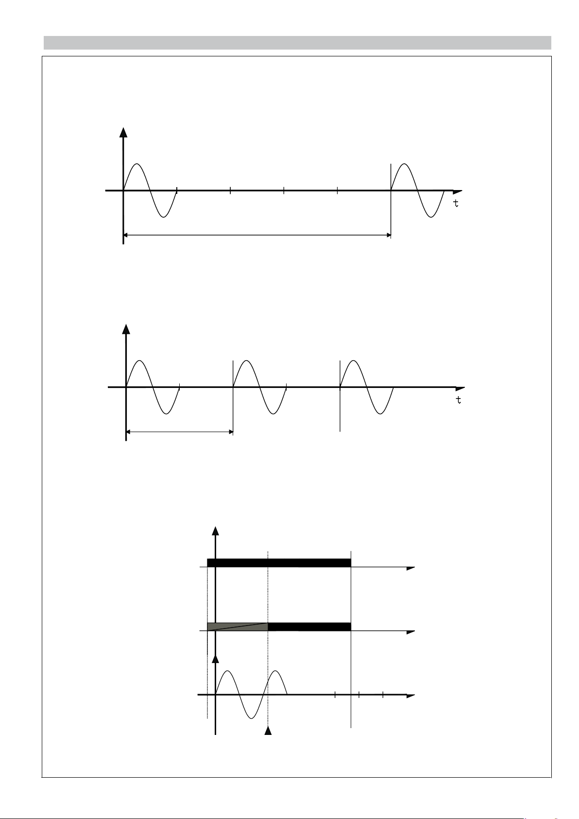
WORKING TYPOLOGY
“Zero crossing” with variable cycle time
Examples of the operation of the GTT for different values of the input drive signal and the consequent different cycle times
(100msec and 40msec respectively)
V
V
Example of input at 20% = 2V (IN 0-10V) or 4mA (IN 0-20mA)
V=Voltage across load
100msec
Logic output control for GTT
Example of input at 50% = 5V (IN 0-10V) or 10mA (IN 0-20mA)
V=Voltage across load
GTT thermal protection
40msec
Control
input
ON
OFF
t
Red LED ONRed LED
Thermal alarm
t
V = Load voltage
t
Thermal protection
activation
Page 4
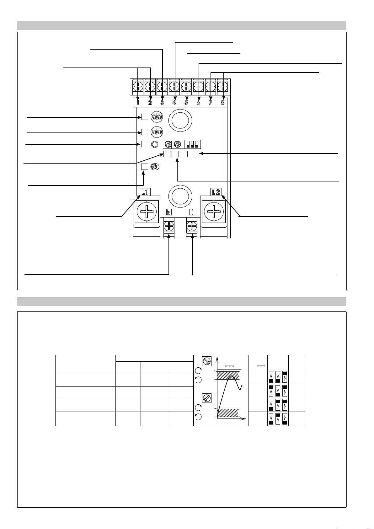
FACEPLATE DESCRIPTION
g
c
b
f
e
d
a
Synchronism signal for
Master/Slave connection
Alarm output
(solid state relay, HB option)
Green LED (power on),
Red LED (GTT running)
Red LED (thermal alarm), yellow LED
(load interrupt alarm, HB option)
NOT use
Monorev trimmer for minimum
calibration of input signal
Monorev trimmer for calibration of load
interrupt (HB) alarm limit
LINE connection
- control signal
+ control signal
Reference voltage for potentiometer power supply (+ 10V)
24 V ac 50/60 Hz power terminal
Dip switch for selection of input signal
(S1, S2, S3)
Monorev trimmer for maximum
calibration of load signal
LOAD connection
Reference connection of 230V line voltage
(HB option with 150V to 300V load)
Reference connection of 480V line voltage (HB option
with 300V to 530V load)
CALIBRATION PROCEDURE OF THE INPUT SIGNAL
The solid-state power unit, GTT, is supplied factory calibrated for 0..5V, 0..10V, 0..20mA, 4..20mA inputs, 10Kohm
potentiometer. Minimum and maximum values are adjusted with two monorev trimmers (d,e).
Input signal type is selected with the f adjustment dip switches (S1,S2,S3).
Control signal Dip Switch Position
e
S1 S2 S3
0...5Vdc OFF OFF ON
0...10Vdc ON OFF ON
0...20mA OFF ON ON
4...20mA OFF ON OFF
d
96%
82%
18%
4%
V/mA
In
V/mA
In
0-5V
0-10V
0-20mA
4-20mA
T
f
S1-S3
On
Off
Rin
100K�
100K�
125�
125�
Minimum adjustment trimmer (d) turned fully counterclockwise sets the start conducting limit at 4% of the signal; turned
fully clockwise, the minimum conducting limit is set at 18% of the input signal.
Maximum adjustment trimmer (e) turned fully clockwise sets the full conducting limit at 96% of the signal; turned fully
counterclockwise, the full conducting limit is set at 82% of the input signal<
Page 5

INTERRUPTED LOAD ALARM
The interrupted load alarm function enables the GTT to diagnose a variation of the load current (compared to a set limit),
distinguishing it from one caused by a change in grid voltage. e. The solid state power unit must therefore be supplied with the
voltage applied to the load terminals, i.e.: LOAD (L2): already connected internally;
LINE (h or i): connect terminal h for voltages from 150 to 300V; connect terminal i for voltages from 300 to 530V.
The alarm activates (relay closed and yellow alarm LED on) when the current, during the conduction of the device, falls below
a preset level that may be adjusted using the trimmer on the faceplate.
Calibratio procedure (refer to the faceplate description drawing)
1) Use the adjustment system (or a calibrator) in order to supply the maximum signal (100% conduction or thered “ON” LED
always illuminated). As an alternative, you can configure the GTT to 0-10 V DC input configuration and connect terminals 5
and 6.
2) Use a current sensing pliers to check that the load current is at rated level.
3) Turn alarm limit adjustment trimmer (g) fully clockwise. Check that yellow alarm LED (b) turns on.
4) Slowly turn trimmer (g) counterclockwise until the alarm LED turns off.
5) Turn the trimmer counterclockwise another 1/10 of a turn (1 notch on the scale).
In this way, the alarm limit is set below 10% of the rated load current.
N.B:
the partial load break alarm function operates with power partialization exceeding 15%. For partializations below 20%, tripping
times increase due to the reduced load activation time. For correct operation of the option, the load current has to exceed 30%
of rated current for the GTT.
Notes on use of the GTT with the digital On/Off control
- The logic control signal has to be connected with the correct polarities to terminals 4 and 5 of the analog input.
- Turn minimum adjustment trimmer (d) fully counterclockwise and maximum adjustment trimmer (e) fully clockwise.
- Set the 3 dip switches (f) to off.
For applications with a very short work cycle, you can drive the solid state group by means of the Master/Slave signal by
driving it with a digital signal (OFF = 0 V dc; ON = from 4 V dc to 10 V dc)
Inhibiting the GTT
You can inhibit operation of the GTT by means of the Master/Slave signal.
To inhibit, connect control signal - (4) with the synchronism signal for Master/Slave connection (3).
Notes on use of the GTT in Master/Slave configuration
The GTT can be used as a master to drive other solid state groups (slaves). With Master/Slave signal (3), you can drive up to
9 GTTs (see connection examples for GTT solid state power relays with three-phase load). You can also use a GTT to drive
GTS solid state power relays (maximum of 2), as shown in the connection diagrams for GTT/GTS solid state power relays with
three-phase load (attention: the HB option cannot be used for a three-phase application with neutral).
Page 6

DISSIPATION CURVES
Rated current curves based on room temperature.
GTT 25 / 40 GTT 50 / 60
GTT 75 / 90 / 120
The GTT 120 curves refer to the device complete with standard fan running.
TABLE FOR TERMINAL CHOICE OF POWER TERMINAL BOARD
CONTROL TERMINAL POWER TERMINAL GROUND TERMINAL *
Size
25/40A
50/60A
75-90A
120A
Contact
area
(WxD)
screw
type
6,3X9
M3
6,3X9M3Eye/fork
6,3X9M3Eye/fork
Pre-
isolated
wire
terminal
Eye/fork
tip
tip
tip
Max. section **
conductor
tightening
torque
2,5mm²
0,6Nm Max
2,5mm²
0,6Nm Max
2,5mm²
0,6Nm Max
Contact
area
(WxD)
screw
type
16x18
M6
16x18
M6
16x18
M6
Pre-
isolated
wire
terminal
Eye/fork 50mm²
Eye/fork
Eye/fork
Max. section **
conductor
tightening
torque
3,5-0,6Nm
50mm²
3,5-0,6Nm
50mm²
3,5-0,6Nm
(**)The maximum sections indicated refer to unipolar copper wires with PVC insulation.
• Note: you have to use an eye terminal for the ground connection.
(WxD) = width x depth
Contact
area
(WxD)
screw
type
14x16
M5
14x16
M5
14x16
M5
Max. section **
conductor
tightening
torque
50mm²
1,8-2,5Nm
50mm²
1,8-2,5Nm
50mm²
1,8-2,5Nm
Page 7

DIMENSIONS AND CUT-OUT
108 mm
100 mm
18mm
depth = 142mm (*)
weight = 900g
GTT 25- GTT 40 GTT 50 - GTT 60
GTT 75 (without fan)
GTT 90 (without fan)
60 mm 80 mm 127 mm
1
2
4
3
5
7
6
Alarm
Out
30 Vdc/ac
ON
c Reset Alarm
d Min Adj
e Max Adj
f Input selection
g Alarm Adj
Line
L1
Master
-
Slave
PWR
AL
GTT 25A/480 Vac
AC1 50/60 Hz
Line
230 V
h
8
+10 Vdc
24 Vac
+
Out
Supply
Analog
Input
0..20mA
4..20mA
0..5V
0..10V
Line
Load
480 V
i
L2
1
2
Alarm
Out
30 Vdc/ac
ON
c Reset Alarm
d Min Adj
e Max Adj
f Input selection
g Alarm Adj
Line
L1
4
3
-
Master
Slave
PWR
AL
GTT 60A/480 Vac
AC1 50/60 Hz
Line
230 V
h
5
7
6
8
+
+10 Vdc
24 Vac
Out
Supply
Analog
Input
0..20mA
4..20mA
0..5V
0..10V
Line
Load
480 V
L2
i
depth = 142mm (*)
weight = 1200g
GTT 120 (with fan)
1
2
4
3
5
7
6
+
-
+10 Vdc
Alarm
Out
30 Vdc/ac
ON
c Reset Alarm
d Min Adj
e Max Adj
f Input selection
g Alarm Adj
Line
L1
Master
Slave
PWR
AL
GTT 120A/480 Vac
AC1 50/60 Hz
Line
230 V
h
24 Vac
Out
Supply
Analog
Input
0..20mA
4..20mA
0..5V
0..10V
Line
Load
480 V
L2
i
8
30mm
50mm (max)
TEMPLATE DIMENSIONS
depth = 142mm
weight GTT 90 = 1300g
weight GTT 120 = 1700g
W
M5
L
GTT 25 - 40 - 50 - 60
GTT 75 - 90 - 120
L (mm)
112
112
W (mm)
44
113
Page 8

CONNECTION EXAMPLES
Phase T
Single-phase connection with optional monitoring of interrupted load (command input from analog signal or potentiometer)
Digital output
0-20mA
4-20mA
0-10Vdc
Relay output - Alarm
(solid state relay)
Connections regarding the
*
load interrupted option (see
paragraph “Interrupted load
alarm)
Note: connect h or i
according to the load
tension.
*
2
1
3
456
78
Master
-
Slave
PWR
AL
GTT 25A/480 Vac
AC1 50/60 Hz
Line
230 V
+
+10 Vdc
24 Vac
Out
Analog
Supply
Input
24Vac 1,5VA
0..20mA
4..20mA
0..5V
0..10V
Line
Load
480 V
L2hL1 i
Alarm
Out
30 Vdc/ac
ON
c Reset Alarm
d Min Adj
e Max Adj
f Input selection
g Alarm Adj
Line
Potentiometer
Controller
0-5Vdc
Load
Phase
Fuse
* *
Neutral
Ground
Star or delta three-phase connection without neutral, with control of two phases.
*
Connections regarding
*
the load interrupted
option (see paragraph
“Interrupted load alarm)
Note: connect h or i
according to the load
tension.
12
Alarm
Out
30 Vdc/ac
ON
c Reset Alarm
d Min Adj
e Max Adj
f Input selection
g Alarm Adj
Line
L1
Master
Slave
PWR
AL
GTT 25A/480 Vac
AC1 50/60 Hz
Line Line
230 V
h
4537
6 8 1
24 Vac
+10 Vdc
SupplyOutAnalog Out
Input
0..20mA
4..20mA
0..5V
0..10V
Load
480 V
i L1
L2
2
Alarm
Master65+10 Vdc8724 Vac
Slave
30 Vdc/ac
ON
GTT 25A/480 Vac
c Reset Alarm
d Min Adj
e Max Adj
f Input selection
g Alarm Adj
Line Line
Line
43
PWR
AL
AC1 50/60 Hz
h
Out SupplyAnalog
Input
0..20mA
4..20mA
0..5V
0..10V
Load
480 V230 V
i
L2
Potentiometer
24Vac 3VA
Three-phase connection
Relay output - Alarm
(Solid state relay)
Star connection
Controller
Digital output
0-20mA
4-20mA
0-10Vdc
0-5Vdc
Ground
Phase R
Phase S
Fuse Fuse
* * * *
Page 9

CONNECTION EXAMPLES
Phase T
Three-phase star connection with neutral.
* * *
21
3
54
Ground
Fuse
Alarm
Out
30 Vdc/ac
ON
c Reset Alarm
d Min Adj
e Max Adj
f Input selection
g Alarm Adj
Line
L1
Master
Slave
PWR
AL
GTT 25A/480 Vac
AC1 50/60 Hz
Line
230 V
h
Analog6Out
Input
0..20mA
4..20mA
0..5V
0..10V
+10 Vdc
Line
480 V
i
Relay output - Alarm
(solid state relay)
Digital output
0-20mA
4-20mA
Controller
0-10Vdc
0-5Vdc
Potentiometer
1
234
5 6
21
3
54
87
Alarm
24 Vac
Supply
30 Vdc/ac
Master
Out
Slave
ON
PWR
Analog6Out
Input
87
+10 Vdc
24 Vac
Supply
30 Vdc/ac
Alarm
Master
Out
Slave
ON
AL
GTT 25A/480 Vac
AC1 50/60 Hz
0..20mA
c Reset Alarm
d Min Adj
4..20mA
e Max Adj
0..5V
f Input selection
0..10V
g Alarm Adj
Line
Line
Load
L2
Line
230 V
L1
Load
480 V
i
h
Fuse
c Reset Alarm
d Min Adj
e Max Adj
f Input selection
g Alarm Adj
Line
L2
L1
Fuse
Analog
Input
PWR
AL
GTT 25A/480 Vac
AC1 50/60 Hz
Line
230 V
h
78
24 Vac+10 Vdc
Supply
Out
Connections regarding the
24Vac 4,5VA
*
load interrupted option (see
paragraph “Interrupted load
0..20mA
4..20mA
0..5V
0..10V
Line
Load
480 V
i
L2
alarm)
Note: connect h or i according
to the load tension.
Load
Neutral
* * * * * *
Phase R
Phase S
Star or delta three-phase connection without neutral, with control of three phases.
Connections
*
regarding the
load interrupted
option (see
paragraph
“Interrupted load
alarm)
Note: connect h
or i according to
the load tension.
* *
21
3
54
Analog6Out
Input
0..20mA
4..20mA
0..5V
0..10V
480 V
87
+10 Vdc
24 Vac
Supply
Line
Load
i
L2
Fuse
Alarm
Out
30 Vdc/ac
ON
c Reset Alarm
d Min Adj
e Max Adj
f Input selection
g Alarm Adj
Line
L1
Master
Slave
PWR
AL
GTT 25A/480 Vac
AC1 50/60 Hz
Line
230 V
h
Fuse
Alarm
Out
30 Vdc/ac
ON
c Reset Alarm
d Min Adj
e Max Adj
f Input selection
g Alarm Adj
Line
L1
21
3
Master
Slave
PWR
AL
GTT 25A/480 Vac
AC1 50/60 Hz
Line
230 V
h
54
Analog6Out
Input
0..20mA
4..20mA
0..5V
0..10V
+10 Vdc
Line
480 V
i
*
1
2 34
5 6
87
Alarm
Master
Out
30 Vdc/ac
Slave
24 Vac
Supply
ON
c Reset Alarm
d Min Adj
e Max Adj
f Input selection
g Alarm Adj
Load
L2
Line
230 V
L1
Fuse
Analog
Input
PWR
AL
GTT 25A/480 Vac
AC1 50/60 Hz
Line
h
78
24 Vac+10 Vdc
Supply
Out
0..20mA
4..20mA
0..5V
0..10V
Line
Load
480 V
i
L2
24Vac 4,5VA
Relay output - Alarm
(solid state relay)
Potentiometer
Load
Controller
Digital output
0-20mA
4-20mA
0-10Vdc
0-5Vdc
Ground
Phase R
Phase S
Phase T
* ** *
* *
Page 10

CONNECTION EXAMPLES
Phase T
Phase T
Three-phase connection (triangle or star) without neutral, with control of two phases using one GTT in Master configuration
and one GTS in Slave configuration.
Relay output - Alarm
(solid state relay)
Digital output
0-20mA
4-20mA
Controller
0-10Vdc
0-5Vdc
Connections regarding
*
the load interrupted
option (see paragraph
“Interrupted load alarm)
Note: connect h or i
according to the load
tension.
* *
+
6√32Vcc
ON/OFF Control
ON
AL
GTS 60A/480 Vac
AC1 50/60 Hz
Load Line
2
1
Alarm
Master65+10 Vdc8724 Vac
Out
Slave
30 Vdc/ac
ON
PWR
AL
GTT 50A/480 Vac
c Reset Alarm
d Min Adj
e Max Adj
f Input selection
g Alarm Adj
Line Line
Line
L1
h iL2
43
AC1 50/60 Hz
Potentiometer
Out SupplyAnalog
Input
24Vac 1,5VA
0..20mA
4..20mA
0..5V
0..10V
Load
480 V230 V
Three-phase connection
Star connection
Fuse
Fuse
Ground
Phase R
* *
Phase S
Three-phase star connection with neutral using one GTT in Master configuration and two GTSs in Slave configuration.
Digital output
0-20mA
4-20mA
0-10V
0-5V
Potentiometer
6√32Vcc
ON/OFF Control
+
ON
AL
GTS 60A/480 Vac
AC1 50/60 Hz
6√32Vcc
ON/OFF Control
+
ON
AL
GTS 60A/480 Vac
AC1 50/60 Hz
30 Vdc/ac
1
Alarm
ON
234
Out
Master
Slave
PWR
AL
GTT 60A/480 Vac
AC1 50/60 Hz
5 6
78
24 Vac+10 Vdc
Analog
Supply
Out
Input
Controller
24Vac 1,5VA
Ground
Neutral
Phase R
Phase S
c Reset Alarm
d Min Adj
e Max Adj
f Input selection
g Alarm Adj
Load
Line
Load
Line
0..20mA
4..20mA
0..5V
0..10V
Line
Line
L1
Line
Load
480 V
230 V
i
h
L2
Load
Fuse
Fuse
Fuse
Page 11

ACCESSORIES
A wide range of accessories is available (including fuses and fuse holders, supports for fastening DIN bar, ID
plates, thermostats, current transformers and isolation transformers). To choose accessories, see the section
“Solid state relays - Accessories.”
ORDER CODE
Model
GTT
Nominal current
25 25Aac
40Aac
50Aac
60Aac
75Aac
90Aac
120Aac (*)
(*) Specify fan supply: 115Vac or 230Vac
Nominal voltage
Load interrupt
(HB) option
With load
interrupt option
40
50
60
75
90
120
480 480Vac
0 Without option
1
GTT 480
/
-
Please contact GEFRAN personnel for information on availability of codes.
•WARNINGS
-
(for model 120A only)
Fan 80x80x40
230V 14W
Fan 80x80x40
115V 14W
Fan
VEN90
VEN91
WARNING: this symbol indicates danger.
Before installation, please read the following advices:
• follow the indications of the manual scrupulously when making the connections to the instrument.
• use a cable that is suitable for the ratings of voltage and current indicated in the technical specifications.
• if the instrument is used in applications where there is risk of injury to persons and damage to machines or materials, it is essential that it is used with
an auxiliary alarm device.
It is advisable to verify frequently that the alarm device is functional even during the normal operation of the equipment.
• The instrument must NOT be used in environments where there could be the presence of dangerous atmospheres (inflammable or explosive).
• During continuous operation, the heatsink may reach 100°C and remain at a high temperature due to thermal inertia even after the device is switched
off. Therefore, DO NOT touch the heat sink or the electrical wires.
• do not operate on the power circuit untless the main supply is disconnected.
• DO NOT open the cover if device is “ON”!
(use the holes in the cover for eventual re-calibration).
Installation:
• connect the device to the ground using the proper ground terminal.
• the power supply wiring must be kept separate from that of inputs and outputs of the instrument; always check that the supply voltage corresponds to
that indicated on the instrument cover.
• evitare la polvere, l’ umidità, i gas corrosivi, le fonti di calore.
• keep away from dust, humidity, corrosive gases and heat sources.
• The connection cable must be shorter than 3 meters if the current transformer is used.
Maintenance: Check the correct operation of the cooling fans at regular intervals; clean the ventilation air filters of the installation at regular intervals.
• Repairs must be performed only by specialized or appropriately trained personnel. Cut off power to the device before accessing internal parts.
• Do not clean the box with solvents derived from hydrocarbons (trichloroethylene, gasoline, etc.). Using such solvents will compromise the mechanical
reliability of the device. To clean external plastic parts, use a clean cloth wet with ethyl alcohol or water.
Technical service : GEFRAN has a technical service department. Defects caused by use not conforming to the instructions are excluded from the
warranty.
GEFRAN spa reserves the right to make any kind of design or functional modification at any moment without prior notice
This device conforms to European Union Directive 2004/108/CE and 2006/95/CE as amended with reference to generic standards:
EN 61000-6-2 (immunity in industrial environment) EN 61000-6-4 (emission in industrial environment) - EN 61010-1 (safety
regulations).
UL
In Conformity with UL508 - File: E243386
DTS_GTT_07-2015_ENG
 Loading...