

Page 1
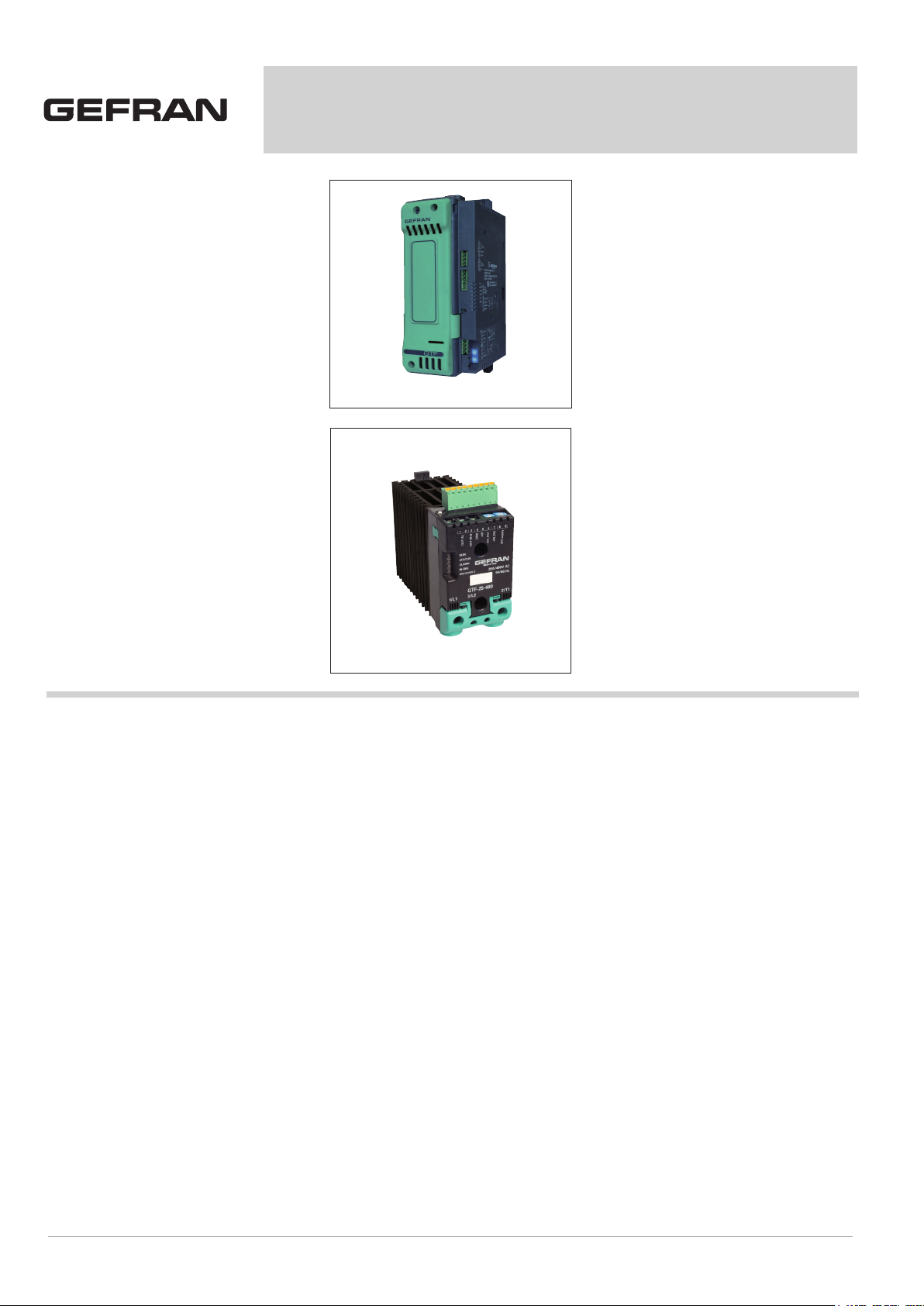
GTF
POWER CONTROLLER
Main applications
• Industrial furnaces for heat treatments,
metallurgy
• Fusion, sinterization, nitruration furnaces
• Furnaces for ceramics and precious
metals
• Dryers
• Heating systems with infrared lamps
(long-, medium-, short-wave)
• Wood edge banding Machines
• Plastic-blowing Machines
• Welding applications on Packaging
Machinery
• Thermoforming Machines
• Furnaces with Super Kanthal™ Silicon
carbide heating elements
Main features
• Current levels from 40A to 250A
• Rated voltage 480Vac, 600Vac and
690Vac
• Trigger congurable in “Zero crossing”
(Fixed Cycle, Burst Firing, Half
single Cycle) or “Phase angle”
• Analog control input, congurable in:
Volt, mA, potentiometer (digital in
PWM)
• Total and partial load interrupt alarm (HB)
(optional)
• Communication Modbus RTU, RS 485 2
wires (optional)
• Current limit (optional)
• V, I, P feedback (optional)
• Connections for monophase and triphase
applications (just in zero crossing”
mode)
• Conguration from PC (by USB – TTL
cable)
•
CE, TÜV, UL Marking
PROFILE
The “GTF” series of microprocessor
advanced solid state power unit controls,
in compact and optimized solutions, offer
various power outputs for use with diffe-
rent types of heating elements. Current
levels range from 25A to 250A, nominal
voltage from 480Vac, 600Vac and 690Vac.
The command input is congurable and
accepts 0-10V, 0/4-20mA signals, poten-
tiometers, logic signals, including with
PWM modes for cost effective solutions.
The device can also be operated via
Modbus RTU serial communication, with
cascade chain connections facilitated by
plug-in RJ10 (telephone) connectors.
The many trigger modes are software con-
gurable and provide:
- ZC:
Zero Crossing constant cycle time (setta-
ble in range 1-200sec), for conventional
loads
-BF: Burst-Firing, Zero crossing with op-
timized minimum cycle time, for systems
with low thermal inertia, medium-wave IR
lamps
- HSC:
Half Single Cycle Zero Crossing (corre-
sponding to Burst Firing) that manages
single semi-cycles of conduction or stop
cycles, useful for short-wave IR lamps,
reduces ickering and limits generation
of EMC noise on the power line (applied
only to single-phase load or 3-phase open
delta 6 leads)
- PA:
Phase angle control, useful for short-wave
IR lamps, transformer primaries.
Completely eliminates ickering of load
laments. Soft Start and soft stop ramp
functions can be assigned to these con-
trols with limitation of current peaks and/or
maximum RMS current level.
Thanks to sophisticated Hardware and
Software solutions, you can precisely
control different types of loads.
Phase angle control matched with cur-
rent limit and current, voltage, or load
power feedback functions, can be used
with “critical” applications such as (for
example), special resistors such as spe-
cial Super Kanthal™ heating elements,
Silicon Carbide resistors, or transformer
primaries.
GTF runs complete diagnostics of current,
voltage, power, and temperature levels:
Current Diagnostics:
- Total and partial load interrupt alarm
- Self-learn function of alarm limit for
interrupted load
- Alarm for SCR in short circuit
- Alarm for load in short circuit or
overcurrent
- Alarm for interrupted internal fuse
Page 2

Voltage Diagnostics:
- Alarm for absence of phase
Temperature Diagnostics:
- Alarm for over temperature of power mo-
dule
The power control with Soft start ramp li-
mits load current peaks at power-on, oop-
timizes the consumptions and increases
the load operating duration.
Installation notes:
- To ensure maximum reliability, it is
essential to install the unit correctly in
the panel in order to guarantee
adequate heat exchange between the
heat sink and the room under natural
convection conditions.
- Install the unit vertically (max 10°
inclination from vertical axis).
- Vertical distance between unit and panel
wall >100mm
- Use the high speed fuses specied in
the catalog
- Applications with solid state power
units must also include an automatic
safety switch to cut out the load power
line.
A specic, linear Soft Start curve, desig-
ned to control gradually the current in the
initial phase is available for IR lamps.
Device parameters can be congured from
PC, by means of a simple conguration
SW which lets you save all parameters in
a conguration le that is easy to manage
and to copy to other devices.
Moreover, an RS485 serial connection of
GTF is offered with Modbus RTU protocol
to control currents, voltages, powers, load
status, and device status from the supervi-
sor terminal (HMI) or PLC.
2
Page 3
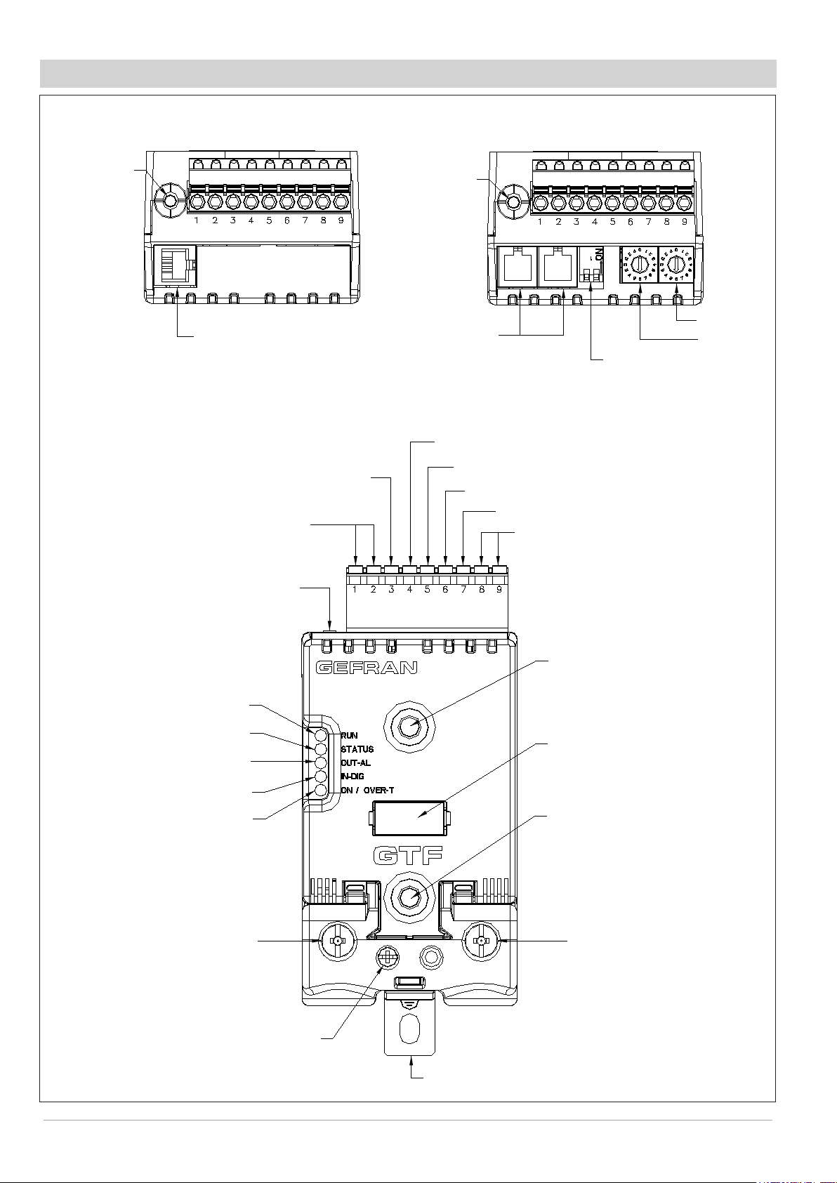
DESCRIPTION OF CONNECTIONS GTF 25-120A
KEY HB
Top view
WITH OUT option Fieldbus
J2
TTL port for
PC conguration
Syncronous output for Ma-
ster/Slave connection
Alarm output
(solid state relay - HB option)
KEY HB
J3, J4
RJ10 connectors
RS485 serial line
Modbus
(GND)
Input control signal (+)
Potentiometer output power supply (+5Vdc)
Top view
WITH option Fieldbus
Address x 1
Address x 10
Switch for serial line
Digital input (PWM input)
Power supply terminal 24Vac/Vdc
Green Led (RUN)
Yellow Led (STATUS)
Red Led (Alarm output HB)
Yellow Led (Status digital input)
Led: Green = Thyristor ON
Yellow = Temperature OVER
1/L1
LINE connection
Key HB
J1
Power supply /control
connector
Fixing screw
at heatsink
Identication label
Fixing screw
at heatsink
2/T1
LOAD connection
3/L2
Reference connection
of line voltage
PE
EARTH
Page 4
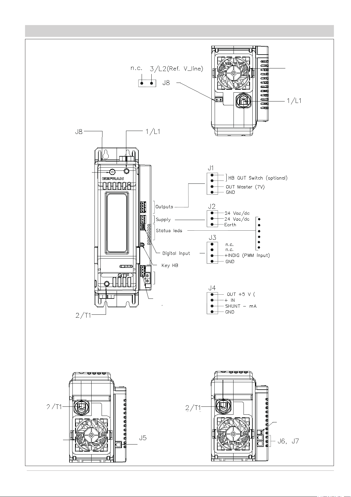
GTF 150-250A DESCRIPTION OF CONNECTIONS
Top View
Line voltage
connector
Protection
fan
“Line”
Connection
Line voltage
connector
Screw front cover
(view fuse)
“Line” Connection
RUN .............................. (Green)
STATUS ........................ (Yellow)
ALARM HB ...................... (Red)
STATE DIGITAL INPUT (Yellow)
ON Thyristor ................. (Green)
OVER Temperature ......... (Yellow)
Address Rotary Switch (optional)
(Potentiometer)
Control analog
input connector
“Load” Connection
Low view WITHOUT option RS485 serial line
“Load”
Connection
Protection
fan
Conguration TTL
means of PC
Low view WITH option RS485 serial line
“Load”
Connection
4
Dip Switch
serial line
RJ10 connectors for
Serial RS485 Modbus
Page 5
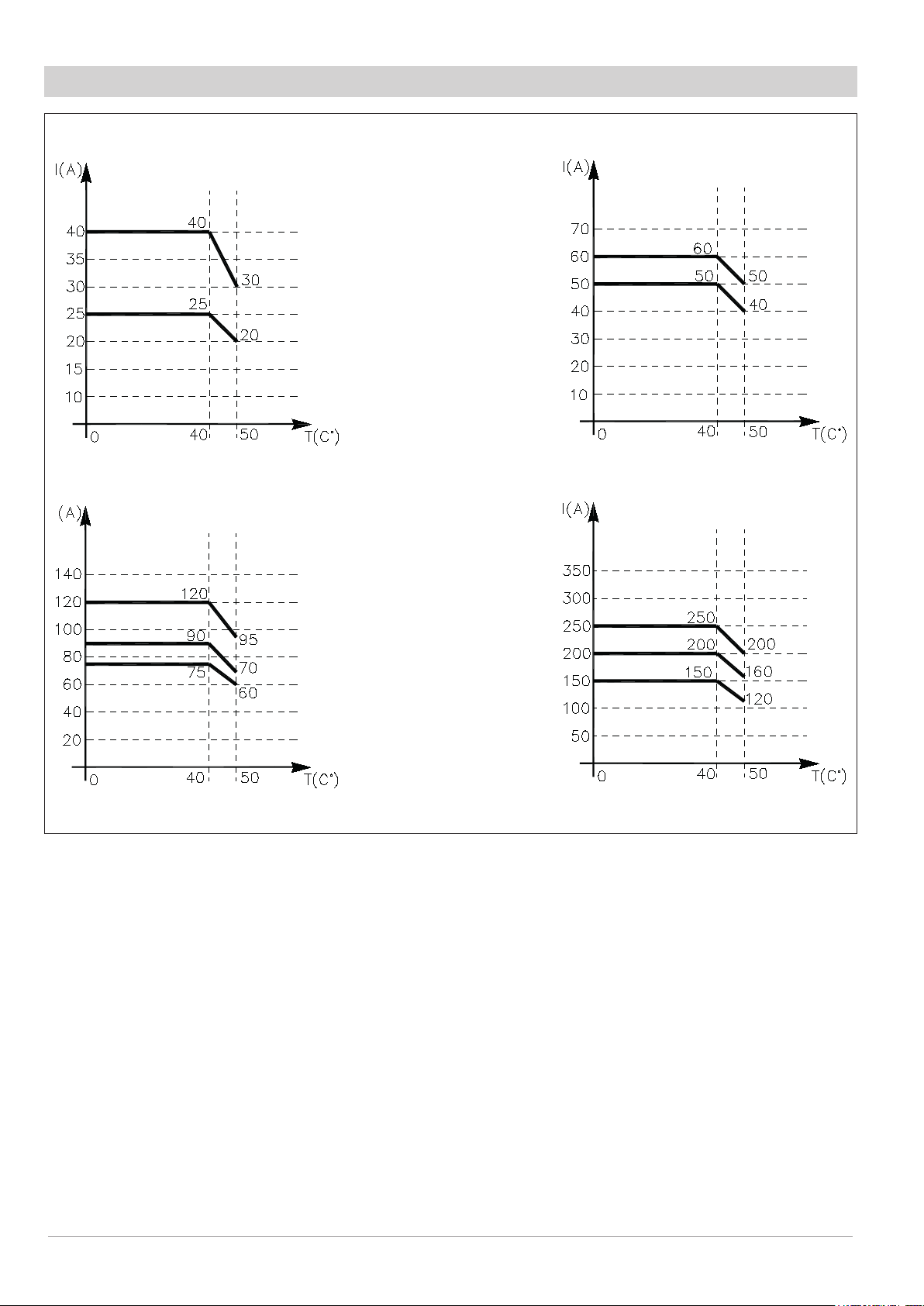
DERATING CURVES GTF
GTF 25 / 40
GTF 75 / 90 / 120 GTF 150 / 200 / 250
GTF 50 / 60
Page 6

FUNCTION MODE
Trigger modes
The GTF provides the following power control modes:
- modulation via variation of phase angle: PA modality
- modulation via variation of number of conduction cycles with “zero crossing” trigger”: ZC, BF, HSC modality.
PA - Phase angle
This mode manages power on the load by modulating load phase angle (only mono-phase)
ex: if power to be transferred to the load is 100%, θ = 180°
ex: if power to be transferred to the load is 50%,, θ = 90°
Zero Crossing mode
This function eliminates EMC noise. This mode controls power on the load via a series of conduction ON and non conduction OFF
cycles.
ZC - Zero Crossing constant cycle time (Tc ≥ 1 sec, settable from 1 to 200 sec) Cycle time is divided into a series of conduction and non
conduction cycles in proportion to the power value to be transferred to the load. (mono-phase or bi-phase).
For example, if Tc = 10sec, if the power value is 20% there is conduction for 2 sec (100 conduction cycles @ 50Hz) and non
conduction for 8 sec (400 non conduction cycles @ 50Hz).
BF - Burst Firing, Zero Crossing variable cycle time (mono-phase or bi-phase).
This mode controls power on the load via a series of conduction ON and non conduction OFF cycles. The ratio of the number of ON cycles
to OFF cycles is proportional to the power value to be supplied to the load.
The CT repeat period is kept to a minimum for each power value (whereas in ZC mode the period is always xed and not optimized).
A parameter denes the minimum number of conduction cycles settable (from 1 to 10). In the example, this parameter = 2
Example of operation in BF mode with power at 50%
6
Page 7

HSC - Half single cycle
This mode corresponds to Burst Firing that manages ON and OFF half-cycles.
It is useful for reducing the flickering of filaments with short/medium-wave IR lamp loads. With these loads, to limit operating current with low
power, it is useful to set a minimum power limit (for example, Lo.p = 10%).
NB: This mode is NOT allowed with inductive loads (transformers). It is used with resistive loads in single-phase, star with
neutral, or open delta configuration.
Advanced single-cycle
Example of operation in HSC mode with power at 33 and 66%
Softstart or Ramp at power-on
This type of start can be enabled in either phase control or pulse train mode, mon-phase.
With phase control, the increment of ring angle stops at the corresponding power value to be transferred to the load.
The control of maximum current spike can be enabled during the ramp phase (this is useful in case of short circuit on the load or loads
with other temperature coefcients to automatically adjust the start time of the load).
The ramp is automatically re-enabled if the GTF remains off for a (settable) time.
Ramp at power-on for resistive loads
DT - “Delay triggering” of rst cycle (only for control modes ZC, BF mon-phase)
Settable from 0° to 90°.
Useful for inductive loads (transformer primaries) to prevent current spike that could in certain cases trip the high-speed fuses that protect
the SCRs.
Page 8

DIMENSIONS
W
L
M5
GTF 25
GTF 40
Depth 143 mm
GTF50 (Without Fan)
GTF60 (Without Fan)
GTF 75 (Without Fan)
GTF 90 (Without Fan)
GTF 120 (With Fan)
Depth 170.4 mm
TEMPLATE DIMENSIONS
L (mm) W(mm)
Models
GTF 25-40-50-60A: 112 44
GTF 75-90-120A: 112 113
GTF 150-200-250A 287 42
8
Page 9

TECHNICAL DATA
General features
Category of use: AC51, AC55b, AC56a
Load type:
AC51 resistive or low-inductance loads
AC55b infrared lamp
AC56a transformers, resistive loads
with high temperature coefcient
Switch-on modes:
ZC Zero crossing constant cycle time
(1-200sec)
BF Burst Firing variable cycle time
(GTT) minimum or optimized
HSC Half Single Cycle corresponds to
Burst Firing that manages
Semi-cycles of on and off.
Useful to reduce ickering with
short-wave infrared loads
PA Phase Angle
Nominal voltage:
480Vac (max range 90-530Vac)
600Vac (max range 90-660Vac)
690Vac (max range 90-760Vac)
Nominal frequency: 50-60Hz
Non-repetitive voltage:
1200Vpk (models 480Vac)
1600Vpk (models 600Vac/690Vac)
Control analog input
Voltage: 0…5Vdc, 0…10Vdc
(impedence >100KΩ)
Current: 0…20mA, 4…20mA
(impedance 125Ω)
Potentiometer: from 1kΩ to 10k Ω
(auto-fed by 5V by GTF)
Digital inputs
Range 5-30V max 7mA
PWM input control: max 100Hz
(Congurable Features).
Voltage line range:
Range: 90… V_nominal_product
Frequency: 50-60Hz
Accuracy: 2% f.s
Current load range:
Range: 0… 2* I_nominal_product
Accuracy: 3% f.s
Sampling 0,2 msec
HB alarm output (optional)
The HB function detects partial or total
load interruption.
The control measures load current by means of an internal device.
The current limit value is set via an automatic procedure activated with the HB
button located near the upper connector.
The alarm output is obtained by means of
a solid relay, with normally open contact
(max 30V, 150mA, maximum conduction
resistance 15Ω).
Modbus RS485 serial (optional)
This option lets you connect the device to
a PC, PLC, HMI with a simple RJ10 telephone wire, by using an RS485 serial
line with Modbus protocol.
The Baud-Rate is congurable from 1200
Baud to 19200 Baud.
A pair of rotary-switches lets you quickly
assign the node address.
A dip-switch near the rotary-switches lets
you internally insert the line termination
resistance. Isolation 300V
OUTPUTS
IsolationHV
Rated isolation voltage input/output:
4000Vac
GTF 25
Nominal current 25 Arms @ 40°C
in continuous service.
Non-repetitive overcurrent t=10ms: 400 A
2
I
t for blowout: 450 A2s
dV/dt critical: 1000 V/μs
GTF 40
Nominal current 40 Arms @ 40°C in continuous service.
Non-repetitive overcurrent t=10ms: 520 A
2
I
t for blowout: 1800 A2s
dV/dt critical:1000V/μs
GTF 50
Nominal current 50 Arms @ 40°C
in continuous service.
Non-repetitive overcurrent t=10ms: 520 A
2
I
t for blowout: 1800 A2s
dV/dt critica: 1000V/μs
GTF 60
Nominal current 60Arms @ 40°C
in continuous service.
Non-repetitive overcurrent t=10ms: 1150A
2
I
t for blowout: 6600 A2s
dV/dt critical: 1000V/μs
GTF 75
Nominal current 75Arms @ 40°C
in continuous service.
Non-repetitive overcurrent t=10ms: 1150A
2
I
t for blowout: 6600 A2s
dV/dt critical: 1000V/μs
GTF 90
Nominal current 90Arms @ 40°C
in continuous service.
Non-repetitive overcurrent t=10ms: 1500A
2
I
t for blowout: 11200 A2s
dV/dt critical: 1000V/μs
GTF 120
Nominal current 120Arms @ 40°C in continuous service.
Non-repetitive overcurrent t=10ms: 1500A
2
I
t for blowout: 11200 A2s
dV/dt critical: 1000V/μs
GTF 150
Nominal current 150Arms @ 40°C
in continuous service.
Non-repetitive overcurrent t=10ms: 5000A
2
I
t for blowout: 125000 A2s
dV/dt critical: 1000V/μs
GTF 200
Nominal current 200 Arms @ 40°C
in continuous service.
Non-repetitive overcurrent t=10ms:8000A
2
I
t for blowout: 320000 A2s
dV/dt critical: 1000V/μs
GTF 250
Nominal current 250Arms @ 40°C iin continuous service.
Non-repetitive overcurrent t=10ms: 8000A
2
I
t for blowout: 320000 A2s
dV/dt critical: 1000V/μs
Thermic Dissipation:
GTF models dissipate thermic power
based on load current:
Pdissipation = I_load_Arms * 1.3V (W)
For 150, 200, 250 A models with
integrated fuse, also consider dissipated
power at rated current shown on the fuse
table.
LED
N.5 LEDs indicator:
RUN (green)
STATUS (yellow)
ALARM (red)
DIGITAL INPUT (yellow)
ON / OVER-TEMP. (green / yellow)
Power supply (model GTF 25-120A)
24Vdc/Vac +/-25%
Input @ 25Vdc: max 100mA
Power: max 3VA
Maximum voltage insulation from control
signals: 300 V
Power supply (model GTF 150-250A)
24Vdc/Vac +/-25%
Input @ 25Vdc: max 450mA
Power: max 11VA
Maximum voltage insulation from control
signals: 300 V
Fan Power supply
(only for model GTF 120A):
24Vdc/+/-10%
Input @ 25Vdc: max 200mA
Ambient conditions:
Working temperature: 0-50°C (see the derating curve)
Storage temperature: -20°C - +70°C
Max. relative humidity: 85% not condensing
Max. installation altitude: 2000m slm
Pollution level: 2
Page 10

Installation
For models 25-120A bar DIN EN50022
For models 150-250A panel
Dimensions:
see dimensions and installation
Weight
GTF 25/40 0,81 Kg
GTF 50/60 0,97 Kg
GTF 75/90 1,3 Kg
GTF 120 1,5 Kg
GTF150/200/250 2,6 Kg
with integrated fuse
ELECTRICAL CONNECTION
POWER CONNECTION
SECTION CABLES RECOMMENDED
GTF CURRENT LEVEL TERMINAL CABLE WIRE WIRE TERMINAL
2
25A 1/L1, 2/T1, PE
40A 1/L1, 2/T1, PE
50A 1/L1, 2/T1, PE
60A 1/L1, 2/T1, PE
75A 1/L1, 2/T1, PE
90A 1/L1, 2/T1, PE
120A 1/L1, 2/T1, PE
- 3/L2 (Ref. Vline)
150A 1/L1, 2/T1
200A 1/L1, 2/T1
250A 1/L1, 2/T1
- 3/L2 (Ref. Vline)
4 mm
10 AWG
2
10 mm
7 AWG
2
10 mm
7 AWG
2
16 mm
5 AWG
2
25 mm
3 AWG
2
35 mm
2 AWG
2
50 mm
1/0 AWG
0.25 ...2.5 mm
23...14 AWG
2
70 mm
2/0 AWG
2
95 mm
4/0 AWG
2
120 mm
250 AWG
0.25 ...2.5 mm
23...14 AWG
Wire terminal / Eye D.
6mm
Wire terminal / Eye D.
6mm
Wire terminal / Eye D.
6mm
Wire terminal / Eye D.
6mm
Wire terminal / Eye D.
6mm
Wire terminal / Eye D.
6mm
Wire terminal / Eye D.
6mm
2
2
wire terminal tip
Wire stripped for 25 mm or
with crimped pre-insulated
terminal tube CEMBRE
PKC70022
Wire stripped for 25 mm or
with crimped pre-insulated
terminal tube CEMBRE
PKC95025
Wire stripped for 25 mm 6 Nm / No. 6 hex head wrench
Wire stripped for 8 mm
or with tag terminal
TIGHTENING TORQUE /
TOOL
2.5 Nm / Phillips screwdriver
PH2 - PH3
2.5 Nm / Phillips screwdriver
PH2 - PH3
2.5 Nm / Phillips screwdriver
PH2 - PH3
2.5 Nm / Phillips screwdriver
PH2 - PH3
2.5 Nm / Phillips screwdriver
PH2 - PH3
2.5 Nm / Phillips screwdriver
PH2 - PH3
2.5 Nm / Phillips screwdriver
PH2 - PH3
0.5 ...0.6 Nm / Screwdriver blade
0.6 x 3.5 mm
6 Nm / No. 6 hex head wrench
6 Nm / No. 6 hex head wrench
0.5 ...0.6 Nm / Flat-head screwdriver
tip 0,6 x 3.5 mm
Note: Cables must be copper “Stranded Wire” or “Compact-Stranded Wire” type with maximum operating temperature 60/75°C
10
Page 11

SIGNAL CABLE
GTF 25-120: J1
GTF 150-250: J1, J2, J4
0,2 - 2,5mm
2
24 - 14AWG
GTF 150-250: J5, J7
0,25 - 2,5mm
0,14 - 0,5mm
GTF 150-250: J3
0,25 - 0,5mm
Connector
RJ10 4-4 pin
Nr. Pin Name Description Note
1 GND1 (**) ((*) Insert the line termination in
2 Tx/Rx+ Data reception/transmission (A+)
3 Tx/Rx- Data reception/transmission (B-)
RS 485
4
4
3
2
1
Cable type: at telephone cable for pin 4-4 conductor 28AWG
2
2
2
+V (riser-
vato)
23 - 14AWG
28 - 20AWG
23 - 20AWG
the last device on the Modbus
line.
(**) Connect the GND signal
among Modbus devices with a
line distance > 100 m.
Page 12

ORDERING CODE
GTF -
NOMINAL CURRENT
25A 25
40A 40
50A 50
60A 60
75A 75
90A 90
120A 120
150A 150
200A 200
250A 250
NOMINAL VOLTAGE
480V 480
600V 600
690V (**) 690
(**) (Only for model with current ≥150A)
FIELDBUS
0 Absent
M MODBUS RTU
FUSIBLE
0 Absent
Self-contained
1
(for current sizes
>=150A)
DIAGNOSTICS ALARMS
OPTIONS
0 Absent
Alarm breach partial or
1
total of load (HB)
CONTROL OPTIONS
0 Absent
1 Current limit
Current limit
2
and feedback V, I, P
Signal control (congurable)
10V (Default) 1
5V/Potentiometer 2
0-20mA 3
4-20mA 4
PWM/Digital input 5
Trigger modes (congurable)
ZC Z
BF (Default) B
HSC H
PA P
Function type (congurable)
Master (Default) M
Slave S
Slave dual-phase S2
1 B M
Note:
Congurator Standard 1-B-M, if not differently
specied .
Substitution model:
GTS GTF - X - 480 - 0 - 0 - 0 - 0 - 5 - Z - S
GTT without load interrupted option
GTF - X - 480 - 0 - 0 - 0 - 0 - 1 - B - M
GTT with load interrupted option
GTF - X - 480 - 0 - 1 - 0 - 0 - 1 - B - M
GEFRAN spa reserves the right to make aesthetic or functional changes at any time and without notice
12
Page 13

ACCESSOIRES
CONFIGURATION KIT
kit for PC via the USB port (Windows environment) for GTF standard conguration (TTL
KIT PC USB / RS485 o TTL
port) for conguration of GTF with the RS485 option
Lets you read or write all of the parameters of a single GTF
A single software for all models
• Easy and rapid conguration
• Saving and management of parameter recipes
• On-line trend and saving of historical data
Component Kit:
- Connection cable PC USB <----> GTF port TTL
- Connection cable PC USB <----> GTF RS485 port
- Serial line converter
- CD SW GF Express installation
ORDERING CODE
GF_eXK-2-0-0....................................Cod. F049095
FUSE / FUSEHOLDERS
Model
GTF 25
GTF 40...
GTF 50...
GTF 60...
GTF 75...
GTF 90...
GTF 120...
GTF 150...
Size
2
I
t
25A
390A²
50A
1600A²
63A
3080A²
80A
6600A²
125A
6950A²
125A
6950A²
200A
31500A²
EXTRARAPID FUSES
Sign
Form
s
s
s
s
s
s
s
FUS-025
10x38
FUS-050
22x58
FUS-063
22x58
FUS-080
22x58
FUS-125N
FUS-125N
FUS-200S
Model
Code
FWC25A10F
338474
FWP50A22F
338127
FWP63A22F
338191
FWP80A22F
338199
660RF00AT125
338106
660RF00AT125
338106
DN000UB69V200
338930
Power
dissipation @ In
6W
9W
11W
14W
25W
25W
19W
FUSEHOLDERS
Adoption
Acronym Code
PFI-10X38
337134
UR30A@690V
PFI-22X58
337223
UR80A@600V
PFI-22X58
337223
UR80A@600V
PFI-22X58
337223
UR80A@600V
PF-DIN
337092
UR400A@1000V
PF-DIN
337092
UR400A@1000V
GTF
200/250
480V/600V
GTF
200/250
690V
450A
196000A²
400A
150000A²
s
s
FUS-450S
FUS-400S
DN00UB60V450L
338932
DN00UB69V400L
338936
17W
20W
ACCESSOIRES
A wide range of accessories is available (including fuses and fuse holders, supports for fastening DIN bar, ID
plates, thermostats, current transformers and isolation transformers).
To choose accessories, see the section “Solid state relays - Accessories.”
Page 14

• WARNINGS
WARNING: this symbol indicates danger.
Before installation, please read the following advices:
• follow the indications of the manual scrupulously when making the connections to the product.
• use a cable that is suitable for the ratings of voltage and current indicated in the technical specications.
• if the instrument is used in applications where there is risk of injury to persons and damage to machines or materials, it is essential that it is used with an
auxiliary alarm device.
It is advisable to verify frequently that the alarm device is functional even during the normal operation of the equipment.
• The product must NOT be used in environments where there could be the presence of dangerous atmospheres (inammable or explosive).
• During continuous operation, the heatsink may reach 100°C and remain at a high temperature due to thermal inertia even after the device is switched off.
Therefore, DO NOT touch the heat sink or the electrical wires.
• do not operate on the power circuit untless the main supply is disconnected.
• DO NOT open the cover if device is “ON”!
Installation:
• connect the device to the ground using the proper ground terminal.
• the power supply wiring must be kept separate from that of inputs and outputs of the instrument; always check that the supply voltage corresponds to that
indicated on the instrument cover.
• Delete this line entirely.
• keep away from dust, humidity, corrosive gases and heat sources.
Maintenance: Check the correct operation of the cooling fans at regular intervals; clean the ventilation air lters of the installation at regular intervals.
• Repairs must be performed only by specialized or appropriately trained personnel. Cut off power to the device before accessing internal parts.
• Do not clean the box with solvents derived from hydrocarbons (trichloroethylene, gasoline, etc.). Using such solvents will compromise the mechanical reliability
of the device. To clean external plastic parts, use a clean cloth wet with ethyl alcohol or water.
Technical service: GEFRAN has a technical service department. Defects caused by use not conforming to the instructions are excluded from the warranty.
GEFRAN spa reserves the right to make any kind of design or functional modification at any moment without prior notice
CSA
UL
Conformity TC RU C-IT.AЛ32.B.00422
Conformity C/CSA/US CoFC no. 70002856
This device conforms to European Union Directive 2014/30/EU and 2014/35/EU with reference to standard:
EN 60947-4-3 (product)
Conformity C/UL/US File no. E243386 vol. 1 sez. 5
Only for 480-600V models
This device conforms to TÜV with reference to: EN 60947-4-3
14
 Loading...