

Page 1
Main applications
• Plastics extrusion lines
and injection moulding
machines
• Packing and packaging
machines
• Polymerization plant for
synthetic fibre production
• Rubber moulding
machinery
• Driers for ceramics and
components for the
building industries
• Chemical and
pharmaceutical industries
• Industrial electric furnaces
• Food processing plants
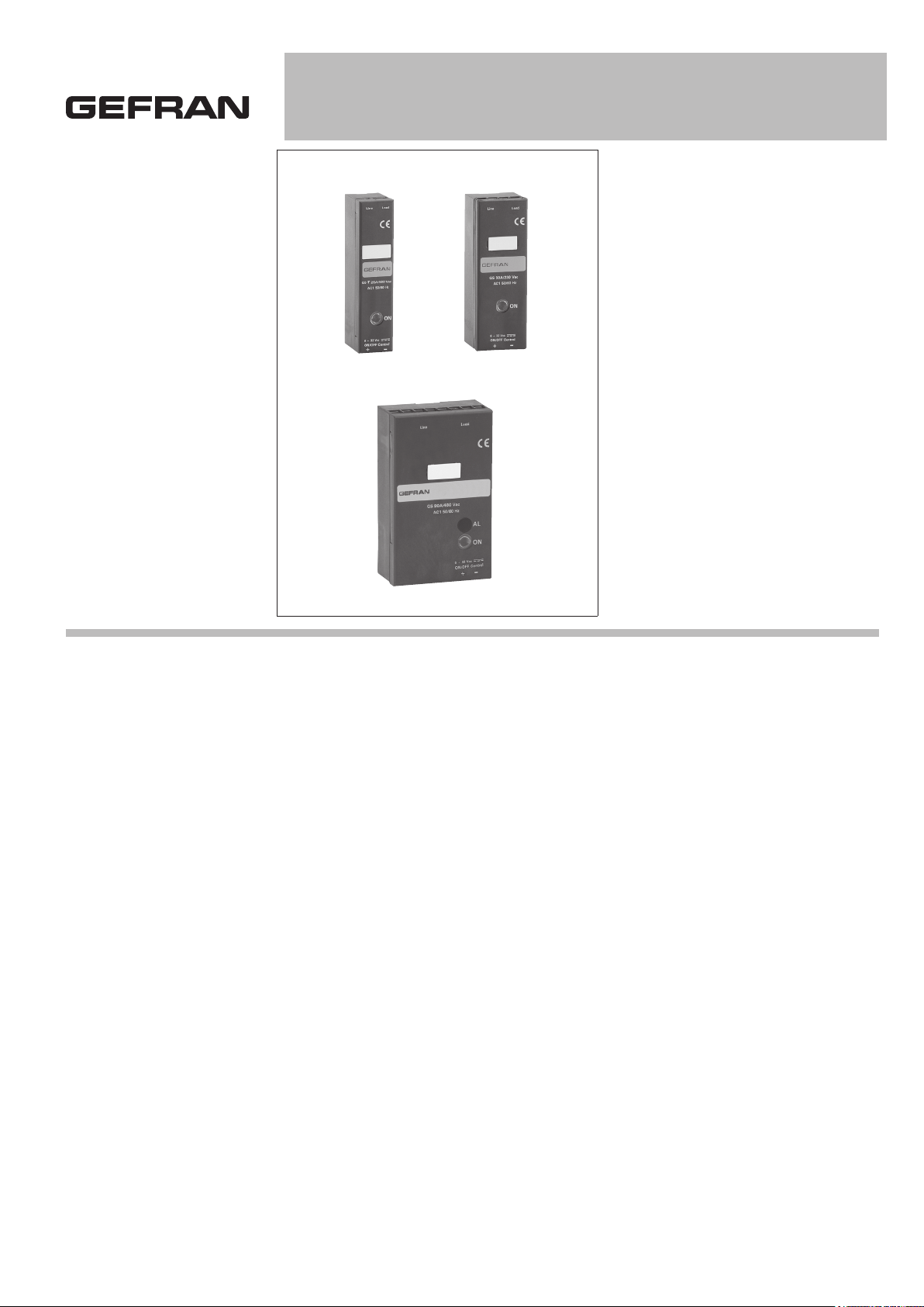
GS 15 / 25 / 40 / 50 / 60 / 75 / 90 / 120A
SOLID STATE RELAYS WITH LOGIC CONTROL
Main features
• Alternating current solid state relay
• Zero crossing switching
• Control input from VDC/VAC logic
signal
• Copper/semiconductor coupling
technology
• 10, 15, 20, 25, 40, 50, 60, 90, and
120 Arms nominal current
• Non-repetitive voltage: up to
1200Vp
• Nominal Voltage: up to 600Vac
• Integrated SCR thermal protection
with LED signal (only for models
with > 40A current)
• 4000 Vrms optoinsulation
(input-output)
• LED, drive input signal indicator
• MOV (varistors)
PROFILE
Zero crossing relay with antiparallel thyristor output is the most used solid state
relay in industrial applications.
“Zero crossing” relay is energised
when voltage meets the zero point
and disenergised when current meets
the zero point, depending on the
signal control on the input circuit.
When the relay has to stand high
currents for a long period, it is necessary to grant a proper dissipation and
an adequate electrical connection
between relay terminals and the load.
Use the relè with an opportune heatsink
(see section accessories).
Varistors, fuses, thermostats and fans
are available as fittings.
ALARM OPTION:
for models with AC control
(Input type = “A”)
OPERATING DESCRIPTION
The alarm output option activates closing
of an isolated contact when it detects the
following fault conditions:
• Control signal active but no current on
load (zero current, interrupted load)
• Control signal active but no power line
voltage (no line)
• Control signal active but SCR / heatsink
is in overtemperature (GS thermal protection)
NOTE: in the absence of the control, the
alarm output is always open (the alarm
memory latch function is not possible, as
with GS with Type “D” input).
ALARM OPTION:
for models with DC control
(Input type “D”)
OPERATING DESCRIPTION.
The alarm output option activates an
isolated contact (or a PNP digital output)
when it detects the following fault conditions:
• Control signal active but no current on
load (Zero Current, Interrupted Load)
• Control signal active but no power line
voltage (no line)
• Control signal active but SCR / heatsink
is in overtemperature (GS thermal protection)
The alarm output is latched: its state is
maintained even when the control signal
is switched off.
The alarm output resets when load current is restored or when the 24V_supply of
the GS is switched off and then on again
(V_supply reset).
The alarm output option is available in the
order code as an isolated contact Solid
State Switch (or as a PNP digital output)
with normally open contact (or normally
deactivated PNP output), or with normally
closed contact (or normally active PNP
digital output).
Page 2
TECHNICAL DATA
B
A
C
D
General features
Category of use: AC1
Nominal voltage
- 230Vac (max. range 24...280Vac)
- 480Vac (max. range 24...530Vac)
- 600Vac (max range 24 ... 660Vac)
Nominal frequency: 50/60Hz
Non-repetitive voltage:
• 500Vp for model with rated voltage
230Vac
• for model with rated voltage 480Vac
• 1400Vp for models with nominal
voltage of 600VAC
Switching voltage for zero: < 20V
Activation time: ≤ 1/2 cycle
Deactivation time: ≤ 1/2 cycle
Potential drop at rated current: ≤ 1.4V
Power factor = 1
Control inputs
DC INPUT (Type “D”):
Max. input: < 10mA@32V
Max. reverse voltage: 36Vdc
AC INPUT (Type “A”):
Control voltage: 20...260VAC/VDC
Activation voltage: > 15VAC /VDC
Deactivation voltage: < 6VAC/VDC
Current draw:
<= 8 mAac/dc@260Vac/Vdc
Alarm output option
Interruption of the load or of the line
commands a contact (solid state switch
or a PNP digital output (max 30V, 150mA
resistance <15 ohm).
Maximum delay in tripping of load interrupt
alarm < 400ms
Maximum length of wires between GS
and load for correct operation of load
diagnostics < 25m
O
uTPuTS
GS 15
Nominal currents of the device with
opportune heatsink in continuous
work:15A
Non-repetitive overcurren t=20 ms: 400A
2
I
t for blowout: ≤450A2s
dV/dt critical with output deactivated:
1000V/µs
GS 25
Nominal currents of the device with
opportune heatsink in continuous work:
25A
Non-repetitive overcurrent t=20 ms: 400A
2
I
t for blowout: ≤645A2s
dV/dt critical with output deactivated:
1000V/µs
GS 40
Nominal currents of the device with
opportune heatsink in continuous work:
40A
Non-repetitive overcurrent t=20 ms: 600A
2
I
t for blowout: ≤1010A2s
dV/dt critical with output deactivated:
1000 V/µs
GS 50
Nominal currents of the device with opportune heatsink in continuous work: 50A
Non-repetitive overcurrent t=20 ms:1150A
2
I
t for blowout: ≤6600A2s
dV/dt critical with output deactivated:
1000 V/µs
GS 60
Nominal currents of the device with opportune heatsink in continuous work: 60A
Non-repetitive overcurrent t=20 ms:1150A
2
I
t for blowout: ≤6600A2s
dV/dt critical with output deactivated:
1000 V/µs
GS 75
Nominal currents of the device with opportune heatsink in continuous work: 75A
Non-repetitive overcurrent t=20 ms:1300A
2
I
t for blowout: ≤8000A2s
dV/dt critical with output deactivated:
1000 V/µs
GS 90
Nominal currents of the device with opportune heatsink in continuous work: 90A
Non-repetitive overcurrent t=20 ms:1500A
2
I
t for blowout: ≤11200A2s
dV/dt critical with output deactivated:
1000 V/µs
GS 120
Nominal currents of the device with opportune heatsink in continuous work: 120A
Non-repetitive overcurrent t=20 ms:1500A
2
I
t for blowout: ≤11200A2s
dV/dt critical with output deactivated:
1000V/µS
Thermal protection
(only on GS models with > 40A current):
The SCR module’s temperature is constantly monitored inside the device. When the
maximum temperature threshold (T=110°C)
is exceeded, current flow to the load is interrupted and the condition is signaled by ligh-
Isolation
Rated isolation voltage input/output :
4000VAC rms SCR version
Thermal features
GS 15
Junction temperature: ≤ 125°C
Rth junction/case: ≤ 2.0 K/W
Rth junction/ambient: ≤ 12.5 K/W
GS 25
Junction temperature: ≤ 125°C
Rth junction/case: ≤ 1.25 K/W
Rth junction/ambient: ≤ 12 K/W
GS 40
Junction temperature: ≤ 125°C
Rth junction/case: ≤ 0.65 K/W
Rth junction/ambient: ≤ 12 K/W
GS 50
Junction temperature: ≤ 125°C
Rth junction/case: ≤ 0.35 K/W
Rth junction/ambient: ≤ 12 K/W
GS 60
Junction temperature: ≤ 125°C
Rth junction/case: ≤ 0.35 K/W
Rth junction/ambient: ≤ 12 K/W
GS 75
Junction temperature: ≤ 125°C
Rth junction/case: ≤ 0.3 K/W
Rth junction/ambient: ≤ 12 K/W
GS 90
Junction temperature: ≤ 125°C
Rth junction/case: ≤ 0.3 K/W
Rth junction/ambient: ≤ 12 K/W
GS 120
Junction temperature: ≤ 125°C
Rth junction/case: ≤ 0.25 K/W
Rth junction/ambient: ≤ 12 K/W
Solid State Relay Dissipated Power
Calculation
Single-phase relay
Pd = 1.4 * IRMS [W] (for GS)
IRMS = single-phase load current
ting of the yellow thermal protection LED.
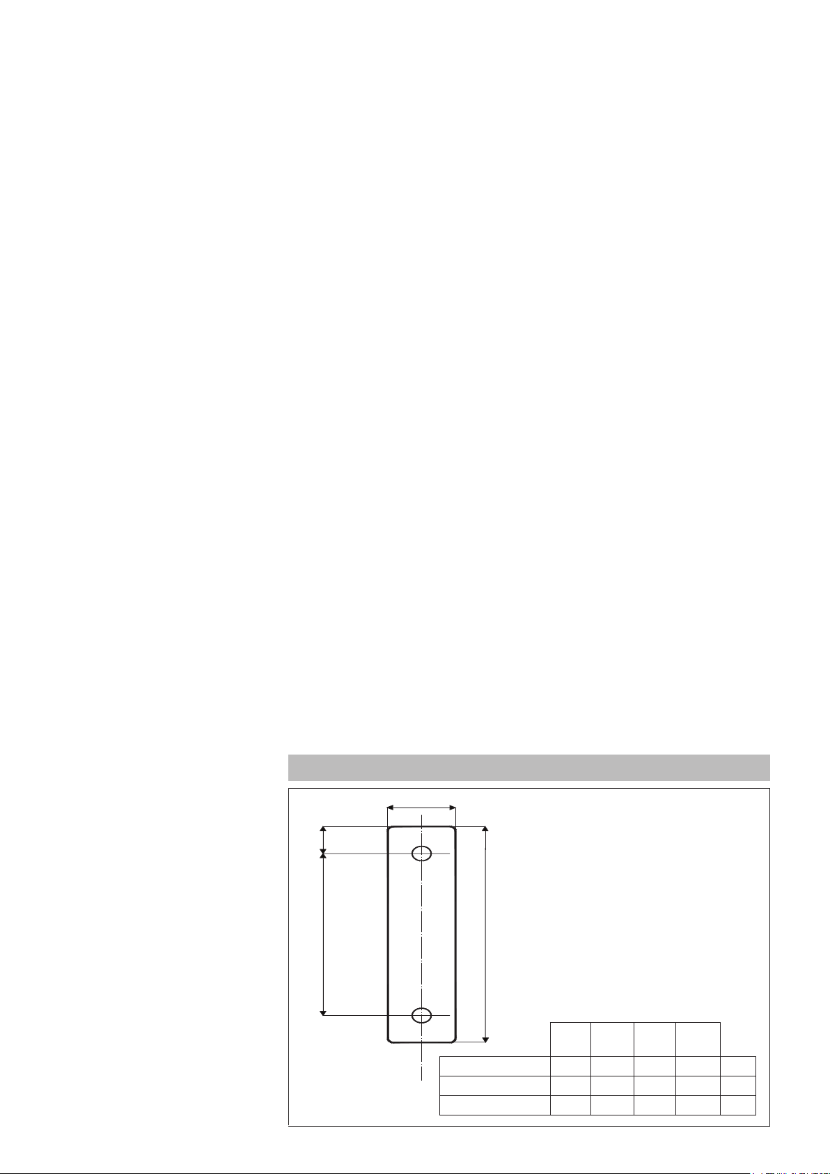
TEMPLATE DIMENSIONS
GS 15-25 18 47,5 100 24 M4
GS 40 20 47,5 100 35 M4
GS 50-60-75-90-120 26 47,5 100 60 M5
A
(mm)B(mm)C(mm)D(mm)
Page 3
Heatsink Thermal Resistance Calculation
Rth = (90°C - max amb. T) / Pd
where Pd = dissipated power
Max. amb. T = max air temperature inside the electrical cabinet.
Use a heatsink with thermal resistance
inferior to the calculated one (Rth).
Ambient conditions
• Working temperature: 0 to 80°C.
• Max. relative humidity: 50% to 40°C
• Max. installation altitude:
2000m asl
• Pollution level 2
• Storage temperature: -20..85°C
Installation notes
- The heat sink must be grounded.
- The device must be protected by an
appropriate high-speed fuse (accessory).
- Applications with solid state power units
must also include an automatic safety
switch to cut out the load power line.
- Protect the solid state relay by using an
appropriate heat sink (accessory).
The heat sink must be sized according to
room temperature and load current (see
the technical documentation).
- Procedure for mounting on heat sink:
The module-heat sink contact surface
must have a maximum planarity error
of 0.05mm. and maximum roughness of
0.02mm. The fastening holes on the heat
sink must be threaded and countersunk.
Attention: spread 1 gram of thermoconductive silicone (we recommend DOW
CORNING 340 HeatSink) on the dissipative metal surface of the module.
The surfaces must be clean and there
must be no impurities in the thermoconductive paste.
Alternately tighten the two fastening
screws until reaching a torque of 0.60 Nm
for the M4 screws and 0.75 Nm for the
M5 screws.
Wait 30 minutes for any excess paste to
drain.
Alternately tighten the two fastening
screws until reaching a torque of 1.2 Nm
for the M4 screws and 1.5 Nm for the M5
screws.
We advise you to randomly check for proper installation by dismantling the module
to make sure there are no air bubbles
under the copper plate.
Limits of use
• dissipation of thermal power of device
with restrictions on temperature of installation site.
• requires exchange with outside air or
an air conditioner to transfer dissipated
power outside the panel.
• installation restrictions (distances between devices to guarantee dissipation by
natural convection).
• max. voltage limits and derivative of transients in line, for which the solid state unit
has internal protection devices (depending on model).
• presence of dispersion current < 3mA
for SCR version GS (max. value with
rated voltage and junction temperature of
125°C).
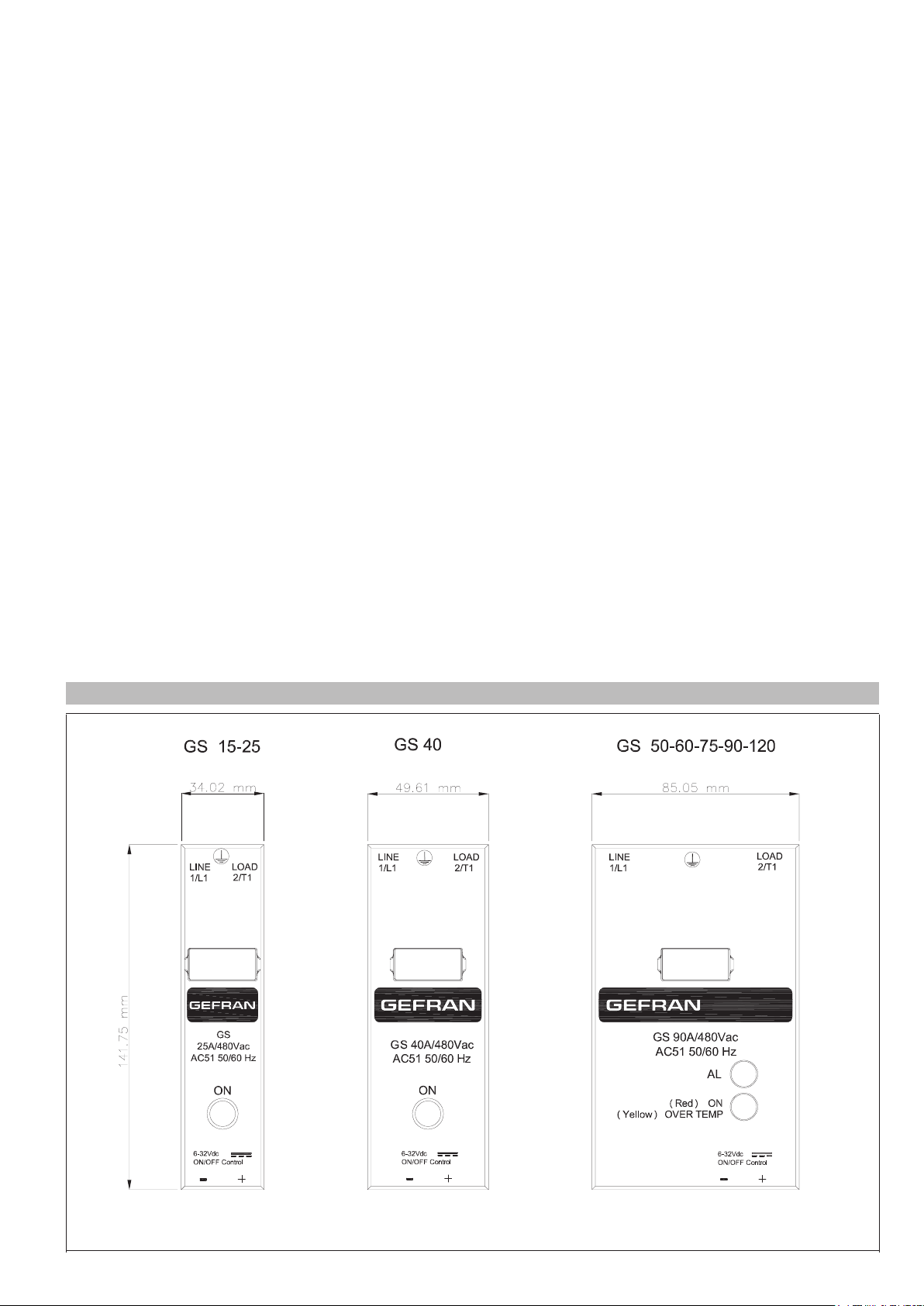
DIMENSIONS AND MOUNTING MEASUREMENTS
depth: 34 mm
weight: 90 gr.
depth: 34 mm
weight: 115 gr.
depth: 34 mm
weight: 200 gr.
Page 4

FACEPLATE DESCRIPTION
View of faceplate (Internal)
(Models with current >40A)
Line
connection
Control I/O
connector
Load
connection
LED signal “AL” (*):
-Red: Alarm output active
- Off: No alarm
(*) available only with alarm output option
LED signal “ON”:
- Red: ON SCR condition
- Yellow: SCR OverTemperature
(Thermal protection ON, SCR OFF)
- Off: No control signal
NOTE:
I “ON” LED is standard
“AL” LED is present only with alarm output option
Description of I/O control terminals (GS > 40A)
Rif. Description Notes for type “D” input Notes for type “A” input
1 Not used
Control input GND
2
ON/OFF
+ Control input
3
ON / OFF
4 (*) Vdc_Supply
5 Not used
6 (*) Alarm output
7 (*) Alarm output
8 Not used
VDC input GND
(Supply GND in case of option)
Range da 6 a 32Vdc, Imax = 10 mA
(1 mA with alarm option)
Supply of optional functions.
(Range 6 to 32 Vdc, Imax < 15 mA)
With Options 1-2:
solid state contact
Imax = 150 mA
Vmax = 30 Vac/dc
Z_closed < 15 Ω
Z_open > 1 MΩ)
With Options 3-4:
Terminal 6 is internally connected to terminal 4 (VDC_Supply)
With Options 3-4:
Terminal 7 is PNP digital output (+)
Imax = 150 mA
Vac/Vdc Inputs
(Range 20 to 260Vac, Imax < 8 mA)
Not used
With Options1:
solid state contact
Imax = 150 mA
Vmax = 30 Vac/dc
Z_closed < 15 Ω
Z_open > 1 MΩ
(*) Optional
Page 5

CONNECTION EXAMPLES
V
Ingresso di controllo
OFF
ON
OFF
ON
LED rosso LED giallo LED giallo
V = Tensione sul carico
t
t
t
Tc
T
Attivazione protezione termica
Control from logic output in voltage
V
Control input
ON ON
V =
Voltage on load
Delivered power = Installed power x TC / T
OFF
ALARM OPTION: FUNCTIONAL DIAGRAM
GS with VDC control (Control type “D”)
GS thermal protection
(only for models >= 50A)
t
GS with VAC control (Control type “A”)
_______________________________________________________________________________
________________________________________________________________________________
IN control
Load current
Alarm output
________________________________________________
Load failure
Load restored
Page 6

CONNECTION EXAMPLES
GS 60A/480Vac
AC51 50/6 0 Hz
LINE
1/L1
AL
LOAD
2/T1
3
2
6-32Vdc
ON/OFF Control
+
-
(Red ) ON
(Yellow )OVER TEMP
GS 60A/480Vac
AC51 50/60 Hz
LINE
1/L1
AL
LOAD
2/T1
3
2
6-32Vdc
ON/OFF Control
(Red ) ON
(Yellow )OVER TEMP
GS 60A/480Vac
AC51 50/60 Hz
LINE
1/L1
AL
LOAD
2/T1
3
2
6-32Vdc
ON/OFF Control
(Red ) ON
(Yellow )OVER TEMP
GS 60A/480Vac
AC51 50/60 Hz
LINE
1/L1
AL
LOAD
2/T1
6-32Vdc
ON/OFF Control
(Red ) ON
(Yellow )OVER TEMP
3
2
GS 60A/480Vac
AC51 50/6 0 Hz
LINE
1/L1
AL
LOAD
2/T1
3
2
6-32Vdc
ON/OFF Control
(Red ) ON
(Yellow )OVER TEMP
GS 60A/480Vac
AC51 50/6 0 Hz
LINE
1/L1
AL
LOAD
2/T1
3
2
6-32Vdc
ON/OFF Control
(Red ) ON
(Yellow )OVER TEMP
Single-phase connection
Phase
Neutral
Ground
Fuse Load
Three-phase Star connection with neutral- GS with VDC control input (Input type “D”)
Phase L1
Phase L2
PhaseL3
Ground
Neutral
Digital output (*)
Controller
Fuse
Fuse
Fuse
Load
Controller
Digital output (*)
Three-phase Triangle or Star connection without neutral on two phases - GS with VDC control input
(Input type “D”)
Phase L1
Phase L2
Phase L3
Ground
Fuse
Triangle
connection
Fuse
Triangle
connection
Load
(*) Or relay output with VAC output
(Use GS with VAC control input, input type“A”)
Controller
Digital output (*)
Page 7

CONNECTION EXAMPLES
Connection example for GS with VDC control with isolated contact alarm output option
(only Models GS-xx/xx-D-1 or GS-xx/xx-D-2 )
(Power connection)
Alarm output (Option 1-2 )
Isolated contact
Max. 30Vac/dc 150mA
Notes:
- Parallel connection with multiple GSs
with N.O. option (Option = 1)
- Serial connection with multiple GSs
with N.C. option (Option = 2
LINE
1/L1
GS 120A /480Vac
AC51 50/60 Hz
AL
Alarm out
Switch
7
(Red ) ON
+24Vdc
Supply
6
4
(Yellow )OVER TE MP.
LOAD
2/T1
6-32Vdc
ON/OFF Control
2
3
24VDC power supply
(6 to 32 Vdc)
On / Off
Control signal
(6 to 32 Vdc)
Connection example for GS with VDC control with PNP alarm output option
(only Models GS-xx/xx-D-3 or GS-xx/xx-D-4 )
(Power
connection)
S upply
AL
4
LO AD
2/T1
6-32V dc
ON /OFF C ontrol
2
3
PNP digital output
Max. 150mA
(Option 3-4)
LI NE
1/L1
G S 120A /480 Vac
AC 51 50/60 H z
Alarm out
S witch
( R ed ) ON
+24V dc
( Y ellow ) OV E R TE MP .
7
24VDC power supply
(6 to 32 VDC)
Notes:
- Parallel connection with multiple GSs with
normally off output option (Option 3)
- Single connection with GS with normally on
output option (Option 4 )
On / Off
Control signal
(6 to 32 VDC))
Page 8

CONNECTION EXAMPLES
Connection example for GS with VDC control with alarm output option (Option 1)
(only Models GS-xx/xx-A-1 )
(Power
connection)
LINE
1/L1
(Yellow )OVE R TEMP .
Alarm out
Alarm Output
Isolated contact
Max. 30VAC/DC 150mA
Notes:
- Parallel connection with multiple GSs with N.O. option
GS 120A/480Vac
AC51 50/60 Hz
(Red ) ON
Switch
6
7
AL
20-260Vac/dc
ON/OFF Control
3
LOAD
2/T1
2
On / Off
VAC control signal
(20 to 260 VAC)
TABLE OF TERMINALS AND CONDUCTORS
CONTROL TERMINAL POWER TERMINAL FIXING SCREWS
Size
15A
25A
40A
50/60A
75-90A
120A
Contact
area
(WxD)
screw
6,4x9M3Eye/fork/conn.
6,4x9M3Eye/fork/conn.
6,3x9
M3
6,3x9
M3
6,3x9
M3
6,3x9
M3
Type of
pre-isolated
wire terminal
type Faston*
type Faston*
Eye/fork typ
Eye/fork typ
Eye/fork typ
Eye/fork typ
Max Sect.**
conductor
tightening torque
2
6mm
0,6Nm Max
2
6mm
0,6Nm Max
2
2,5mm
0,6Nm Max
2
2,5mm
0,6Nm Max
2
2,5mm
0,6Nm Max
2
2,5mm
0,6Nm Max
(*) Female faston (for insertion, remove the M3 screw by making the nut re-enter the seat in the holder)
(**) The max. sections specified refer to unipolar copper wires isolated in PVC.
Contact
area
(WxD)
screw
Type of
pre-isolated
wire terminal
6,4x9M3Eye/fork/conn.
type Faston*
6,4x9
M3
12x12
M5
16x18
M6
16x18
M6
16x18
M6
Eye/fork typ
Eye/fork typ
Eye/fork typ
Eye/fork typ
Eye/fork typ
ACCESSORIES
Max Sect.**
conductor
tightening torque
2
6mm
0,4-0,6Nm
2
6mm
0,4-0,6Nm
2
16mm
1,5-2,2Nm
2
50mm
3,5-6Nm
2
50mm
3,5-6Nm
2
50mm
3,5-6Nm
Contact
area
(WxD)
screw
M4
1,2 Nm
M4
1,2 Nm
M4
1,2 Nm
M5
1,5 Nm
M5
1,5 Nm
M5
1,5 Nm
A wide range of accessories is available (including fuses and fuse holders, heat sinks, ID plates and thermostats).
To choose accessories, see the section “Solid state relays - Accessories”.
Page 9

ORDER CODE
Model
Version with double
SCR
Rated current
15Aac 15
25Aac 25
40Aac 40
50Aac 50
60Aac 60
75Aac 75
90Aac 90
120Aac 120
Rated voltage V
230Vac 24
480Vac 48
600Vac 60
GS
GS
- -
/
-
Alarm Output Option
Available only for GS rated
current ≥ 50A
0 None
Insulated switch
1
output
(normally open)
2 (**)
3 (**)
4 (**)
(**) available only for models with type
“D” input
Insulated switch
output
(normally closed)
Digital PNP output
(normally open)
Digital PNP output
(normally active)
Input type
6 ... 32 Vdc D
20 ... 260 Vac / Vdc A
Please contact GEFRAN personnel for information on availability of codes.
Page 10

•WARNINGS
WARNING: this symbol indicates danger.
Read the following warnings before installing, connecting or using the device:
• follow instructions precisely when connecting the device.
• always use cables that are suitable for the voltage and current levels indicated in the technical specifications.
• in applications with risk of damage to persons, machines or materials, you MUST install auxiliary alarm devices.
• it is advisable to be able to check alarm states during normal operation as well
• DO NOT operate the device in rooms with dangerous (inflammable or explosive) atmosphere.
• During continuous operation, the heat sink can reach up to 100°C, and stays at a high temperature even after the device is turned off due to
thermal inertia; therefore, DO NOT touch it and avoid contact with electrical wires.
• do not work on the power part without first disconnecting electrical power to the panel.
• do not remove the cover when the device is powered!
Installation:
• correctly ground the device using the specific terminal.
• power supply lines must be separated from device input and output lines; always check that the supply voltage matches the voltage indicated
on the device label.
• avoid dust, humidity, corrosive gases and heat sources.
• respect the installation distances between one device and another (to allow for dissipation of generated heat).
• to keep air in movement, we advise you to install a fan near the GST-GS group in the electrical panel containing the GST-GSs.
• respect the indicated dissipation curves
Maintenance: at regular intervals, check operation of the cooling fans and clean all air ventilation filters.
• repairs must be done out only by trained and specialized personnel. Cut power to the device before accessing internal parts.
• do not clean the box with solvents derived from hydrocarbons (trichloroethylene, gasoline, etc.). Using such solvents will compromise the
device’s mechanical reliability. Use a clean cloth moistened with ethyl alcohol or water to clean external parts in plastic.
Service: GEFRAN has a service department. The warranty excludes defects caused by any use not conforming to these instructions.
GEFRAN spa reserves the right to make aesthetic or functional changes at any time and without notice.
UL
This device conforms to European Union Directive 2004/108/CE and 2006/95/CE as amended with reference to generic
standards: EN 61000-6-2 (immunity in industrial environment) EN 61000-6-4 (emission in industrial environment) - EN 61010-1
(safety regulations).
In Conformity with UL508 - File: E243386
DTS_GS_12-2015_ENG
 Loading...