

Page 1
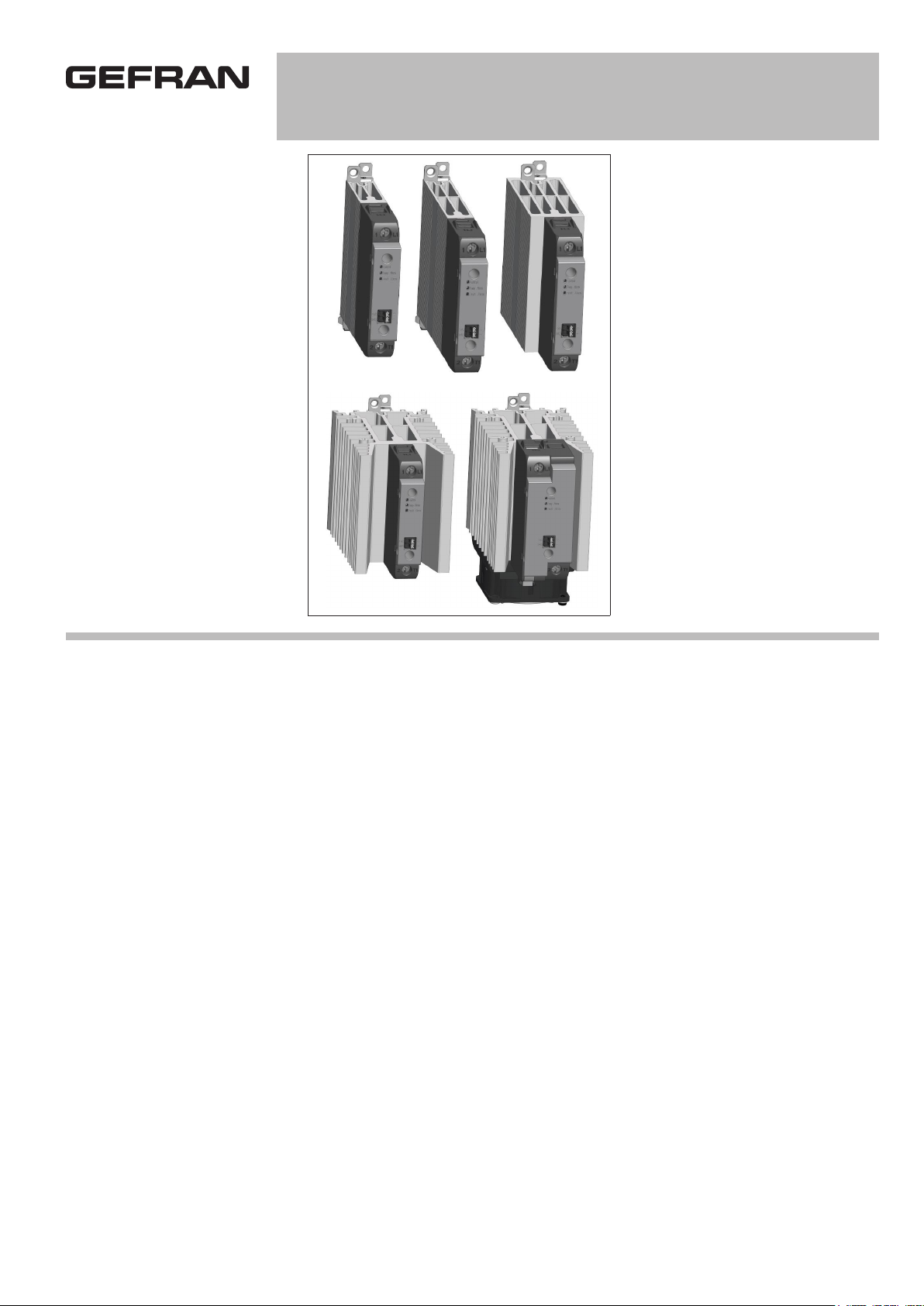
GRS-H 15/25/30/40/50/60/75/90/120A
ULTRA-COMPACT STATIC POWER UNITS
WITH DC / AC LOGIC CONTROL
Main applications
• Extrusion, injection, blow moulding,
thermoforming of plastics
• Vulcanization of rubber
• Synthetic fibre production and
polymerisation
• Packing and packaging
• Dryers for ceramics and building
elements
• Industrial electric ovens
• Food processing plants
• Chemical and pharmaceutical industry
Main features
• Ultra-compact dimensions from 15A to
120A
• DIN rail and panel mounting
• Switching at zero voltage changeover
• Input command from DC/AC logic signal
with push-in connectors; signalling leds
• Cage clamps for power cables
• Load voltage 480V, 600V AC
• Thermal alarm option with led and
alarm output
• Interrupted load option with led and
alarm output
• Internal overvoltage protection
PROFILE
Correct management of electrical
heating elements for industrial heating
applications
requires robust, safe, interferencefree, fast and diagnostically capable
static contactors.
The range of static contactors with
GRS-H heatsink meets all these
requirements, with current ratings
from 15 to 120 Amperes and voltages
up to 600 V AC, with extremely
compact size in every single current
level.
The thermal design of all models
guarantees the continuous supply
of the rated current at an ambient
temperature of 40°C through high
efficiency heat sinks, assisted by fans
for the 90A and 120A models.
The derating curves show how higher
current values can also be achieved,
at lower temperatures, and illustrates
the possibility of mounting various
devices packed together on the DIN
rail.
GRS COMMAND SIGNAL
CONNECTION
The GRS-H series can be controlled
by DC and AC logical signals
managed through push-in connectors
for a faster and easier connection,
even without tools.
The ON / OFF status of the static
device is always displayed by a
green LED on the front panel, for an
immediate view of its operation.
POWER CONNECTIONS
Both the line voltage terminal available
on the upper part of the device and
the load terminal on the lower part are
of the “cage” type, which offers the
best and safest seal even for cables
of different cross-sections, whether
mounted with a cable lug or simply
stripped.
DIAGNOSTICS AND ALARMS
It is increasingly vital for operators
and maintainers to recognize possible
anomalies in the system immediately
and solve them quickly in order to
ensure the efficiency and profitability
of machinery and plants. The GRS-H
series offers a series of diagnostic
information associated with a physical
alarm output with voltage-free or
PNP-type isolated contact.
The thermal alarm is triggered if
heat dissipation exceeds a critical
threshold, signalling it with a yellow
led on the front panel, interrupting the
power supply and triggering the alarm
output (NO or NC). This function is
always present for current levels from
50 A up to 120 A, and is available as
an option for other current levels.
The absence of current on the load (for
models with DC control) is indicated
by a red led on the front panel and by
the activation of the alarm output, as
well as by the absence of line voltage.
Alarm output status is memorized: in
the presence of a 24 V DC auxiliary
power supply, the alarm will be
memorized even in the event of an
OFF command.
The alarm is reset when normal
operating conditions are restored, or
when the 24 V DC auxiliary power
supply is switched off and on again.
Page 2

TECHNICAL DATA
Main features
Category of use: AC51
Rated working voltage
- 480Vac (max. range 24...530Vac)
- 600Vac (max range 24 ... 660Vac)
Rated frequency: 50/60Hz
Non-repetitive voltage:
• 1200Vp for model with rated voltage
480Vac
• 1400Vp for model with rated voltage
600Vac
Switching voltage for zero: < 20V
Activation time: = 1/2 cycle
Deactivation time: = 1/2 cycle
Potential drop at rated current:
= < 1,2Vrms
Power factor = 1
Control input
- DC INPUT (Type “D”):
Max. input: < 9mA @32V
Max. reverse voltage: 36Vdc
Control voltage: 6...32Vdc
Activation voltage: > 5,1Vdc
Deactivation voltage:< 3Vdc
- AC INPUT (Type “A”):
Control voltage: 20...260 Vac/Vdc
INSTALL FUSE (3A MAX) ON THE
CONTROL INPUT CIRCUIT
Activation voltage: > 15Vac/Vdc
Deactivation voltage: < 6Vac/Vdc
Current draw: <= 8 mAac/dc @ 260
Vac/Vdc
alarm output option
(type “D” input Version)
A load or line failure or an overtemperature
alarm commands:
- Options 1/2/5: one voltage-free contact
(solid state N.C or N.O.), max. properties:
- N.O. version 30V-150mA conduction
resistance: ≤ 1Ω
- N.C. version 30V-50mA conduction
resistance: ≤ 15Ω
- Option 3: two normally inactive
(parallelable) PNP digital outputs,
one for load failure and the other for
overtemperature (properties: Imax
=150mA Vout= + V DC power supply
-1V).
Maximum interrupted load alarm trip
delay < 400ms
Maximum cable length between GRS-H
and load for correct load fault diagnostics
< 25m
alarm output option
(type “a” input Version)
The over-temperature alarm commands
a voltage-free contact (solid state N.C.),
max. properties:
30V-50mA conduction resistance: ≤ 15 Ω
outputs
GRS-H 15
Rated current: 15 A@40°C in
continuous service
Non-repetitive overcurrent t=20 ms:
620A
I2t for blowout: ≤ 1800A2s
dV/dt critical with output deactivated:
1000V/µs
GRS-H 25
Rated current: 25 A@40°C in
continuous service
Non-repetitive overcurrent t=20 ms:
620A
I2t for blowout: ≤ 1800A2s
dV/dt critical with output deactivated:
1000V/µs
GRS-H 30
Rated current: 30 A@40°C in
continuous service
Non-repetitive overcurrent t=20 ms:
620A
I2t for blowout: ≤ 1800A2s
dV/dt critical with output deactivated:
1000V/µs
GRS-H 40
Rated current: 40 A@40°C in
continuous service
Non-repetitive overcurrent t=20 ms:
620A
I2t for blowout: ≤ 1800A2s
dV/dt critical with output deactivated:
1000 V/µs
GRS-H 50
Rated current: 50 A@ 40°C in
continuous service
Non-repetitive overcurrent t=20 ms:
1600A
I2t for blowout: ≤ 12800A2s
dV/dt critical with output deactivated:
1000V/µs
GRS-H 60
Rated current: 60 A@ 40°C in
continuous service
Non-repetitive overcurrent t=20 ms:
1600A
I2t for blowout: ≤ 12800A2s
dV/dt critical with output deactivated:
1000V/µs
GRS-H 75
Rated current: 75 A@ 40°C in
continuous service
Non-repetitive overcurrent t=20 ms:
1600A
I2t for blowout: ≤12800A2s
dV/dt critical with output deactivated:
1000V/µs
GRS-H 90
Rated current: 90A@ 40°C in
continuous service (complete with
specified fan)
Non-repetitive overcurrent t=20 ms:
1500A
I2t for blowout: ≤ 11250A2s
dV/dt critical with output deactivated:
1000V/µs
GRS-H 120
Rated current: 120A@ 40°C in
continuous service (complete with
specified fan)
Non-repetitive overcurrent t=20 ms:
1500A
I2t for blowout: ≤ 11250A2s
dV/dt critical with output deactivated:
1000V/µS
THERMAL PROTECTION
(Optional, always present in GRS-H with
current size ≥ 50A):
The temperature of the SCR module is
constantly monitored inside the device.
When the maximum temperature
threshold of the internal SCR is
exceeded, current conduction to the load
is interrupted and the yellow thermal
protection LED comes on to signal the
condition.
Isolation
Rated isolation voltage input/output:
4000VACrms 1min
Ambient conditions
• Working temperature:
from 0 to 80°C (according with
heat sink curves)
• Max. relative humidity:
90% non-condensing at 40°C
• Max. installation altitude:
6600ft above sea level
• Pollution level : 2
• Storage temperature:
-20..+85°C
Page 3
Installation notes
Use the extra-rapid fuse shown in the
catalogue according to the connection
example supplied.
Applications with static units must also
include a safety circuit breaker for
disconnecting the power line from the
load.
To obtain high reliability of the device,
• Horizontal distance between one
device and another at least 20mm
(in the event of installation at shorter
distances, see derating curves).
Make sure that the cable ducts do
not reduce these distances; in this
case, mount the units overhanging the
panel, so that the air can flow vertically
on the heat sink without hindrance.
it is essential to install it correctly inside
the panel in order to obtain adequate
heat exchange between the heat
sink and the surrounding air under
conditions of natural convection.
Mount the device vertically (maximum
10° inclination from the vertical axis)
• Vertical distance between a device
and the panel wall >100mm
• Horizontal distance between a device
and the panel wall at least 20mm
• Vertical distance between one device
and another at least 300mm.
Limits of use
• Ambient temperature limits, depending
on derating curves.
• Need for air exchange with the outside
or an air conditioner to transfer the
dissipated power to the outside of the
panel.
• Installation limits (distances between
devices to ensure dissipation under
natural convection conditions)
• Maximum voltage limits and derivative
of the transients present on the line, for
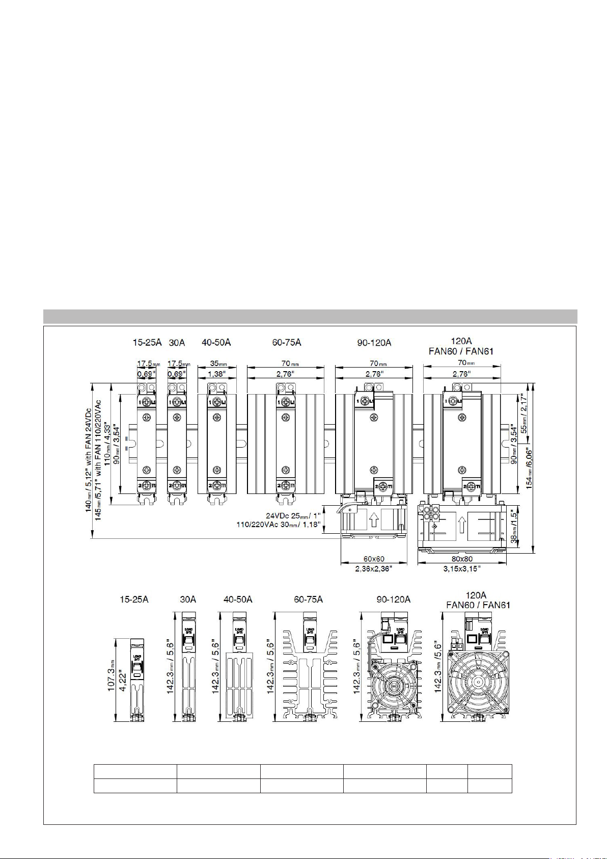
DIMENSIONS AND MOUNTING MEASUREMENTS
which the static unit provides internal
protection devices (depending on the
models).
• Presence of leakage current < 3mA
(max. value with nominal voltage and
junction temperature of 125°C).
Model 15-25A 30A 40-50A 60-75A 90-120A
Weight [g] 194 237 388 688 796
Notes:
The dimensions are representative of all models of the series (command “D” type, “A” type and with options)
Page 4
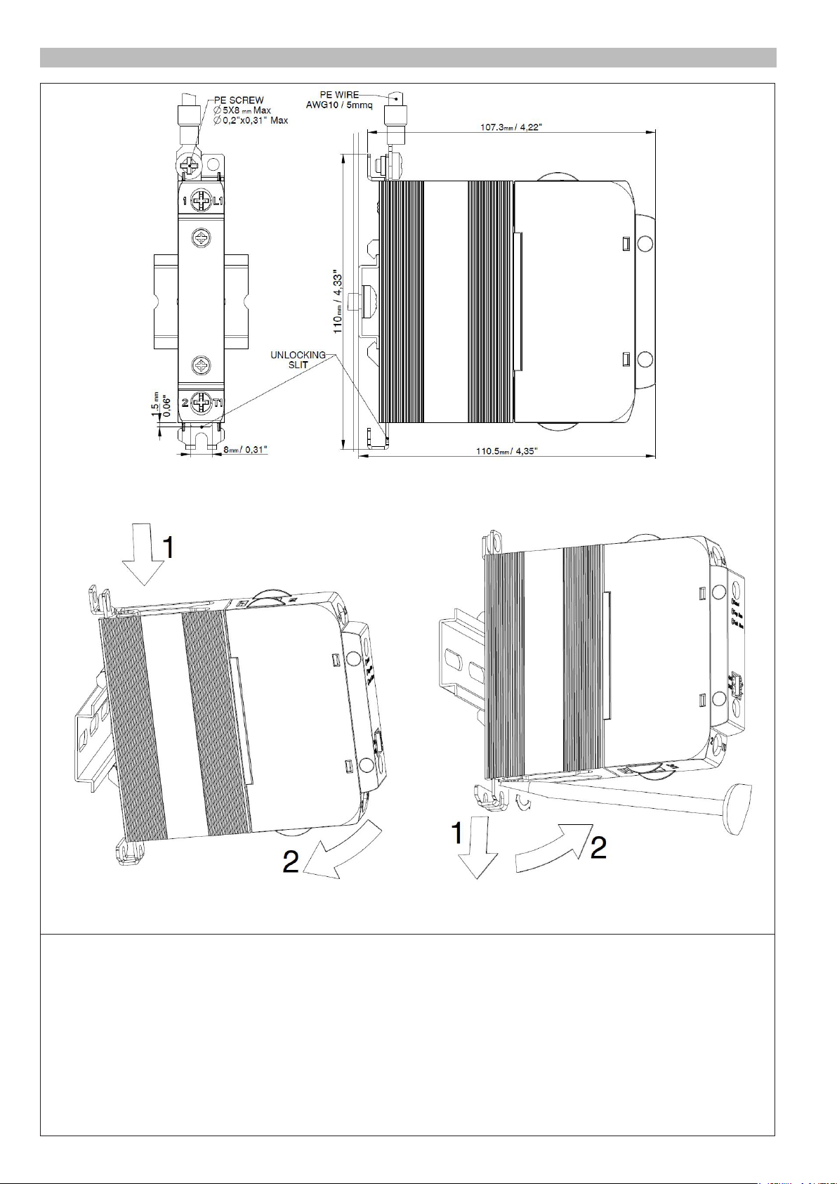
DIN RAIL FIXING
DIN rail coupling sequence DIN rail release sequence
(*) Use of a slotted screwdriver with a max. diameter of 6mm is recommended
SCREW DRIVER (*)
Page 5
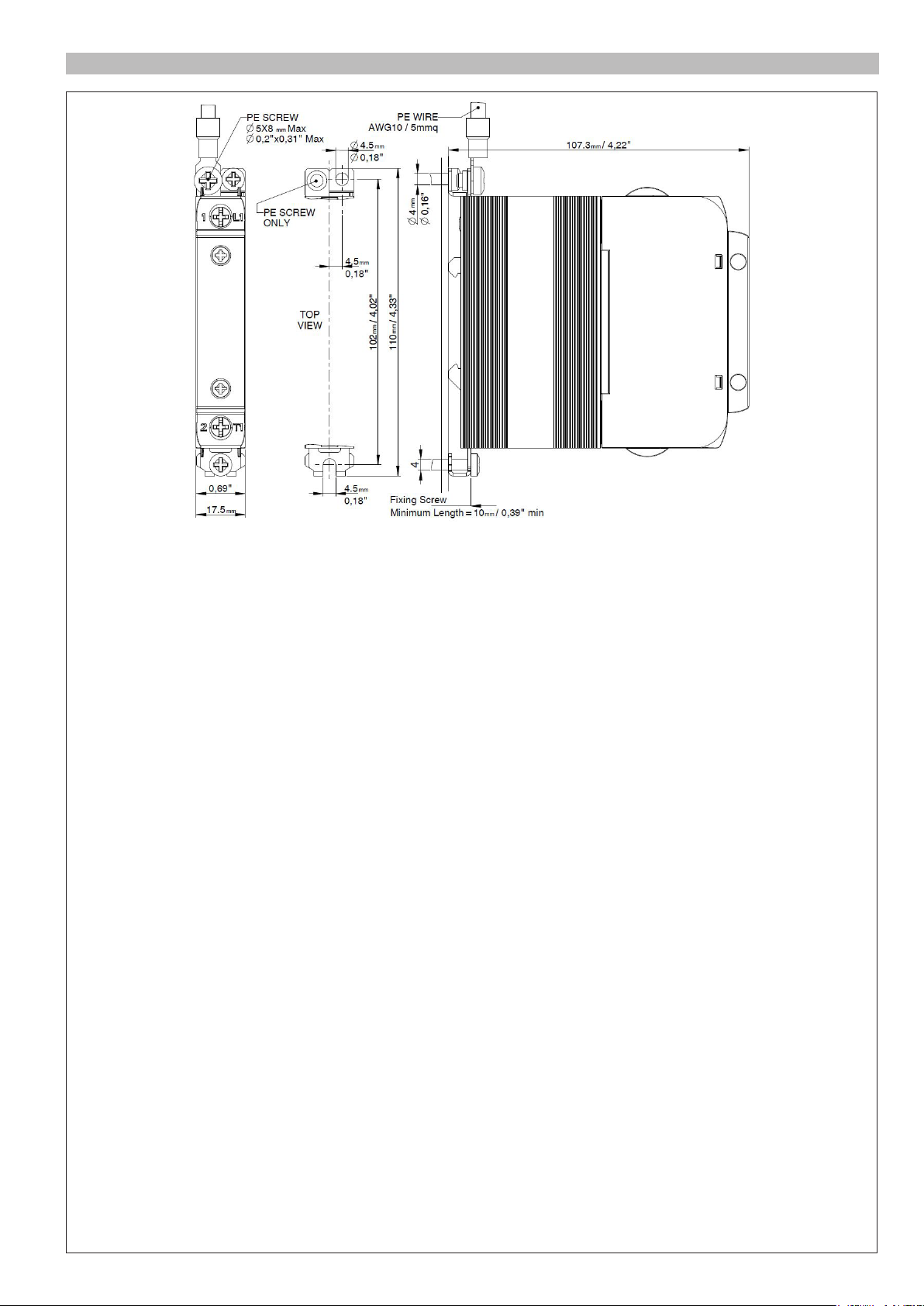
PANEL FIXING
Page 6
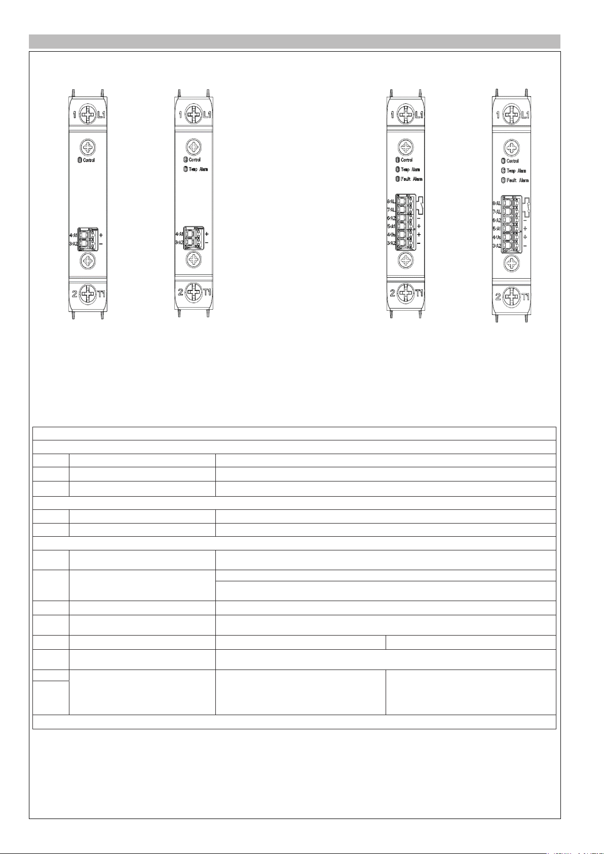
DESCRIPTION OF CONNECTIONS
GRS-H...D-0 GRS-H...D-1 GRS-H...D-2
Description of terminal/connector versions with type “D” input
Power terminals (common to all versions)
Rif. Description Notes
1/L1 Line Connection
2/T1 Load Connection
Signal connector version without options (GRS-H...D-0)
3/A2- GND Control input ON/OFF Control input ground
4/A1+ +Vdc control input ON/OFF Range from 6 to 32 Vdc, Imax <9 mA a 32V
Signal connector version with options “1 “ and “2 “ type (GRS-H…D-1/2)
GND for power supply and control input
3/A2-
ON/OFF
4/Us + Vdc power supply
5/A1+ +Vdc control input ON/OFF Range: ON from 5 to 32Vdc, Imax <0,5 mA a 32V OFF< 1,8V
GND Control input ON/OFF
6/A2-
(common to terminal 3/A2-)
GND Control input ON/OFF
6/A2-
(common to terminal 3/A2-)
7/AL
Alarm output:
- Interrupted load
- Line voltage absent
8/AL
- Overtemperature
Control input ground
Power supply for optional functions (Range from 6 to 32 V DC, Imax < 14 mA at 32V
GRS-H-90..120A-..FAN63: Power supply options + Fan
(Range from 20 to 27 V DC, Imax <150 mA at 24V with Fan active)
Additional connection to be used only as GND for the control signal
Version with option 1 Version with option 2
Additional connection to be used only as GND for the control signal
Solid state N.O. contact
Imax =150mA
Vmax = 30 V DC/25V AC
Z_closed < 1 Ω
Z_open > 1 MΩ
Solid state N.C. contact
Imax = 50mA
Vmax = 30 Vdc/25Vac
Z_closed < 15 Ω
Z_open > 1 MΩ
Note: The connections are also representative of 90-120A models
Page 7

DESCRIPTION OF CONNECTIONS
GRS-H...D-3 GRS-H...D-5
Description of terminal/connector versions with type “D” input
Signal connector version with option type “3” (GRS-H…D-3)
Rif. Description Notes
3/A2- GND for power supply and control input
ON/OFF
4/US + Vdc power supply
5/A1+ +Vdc control input ON/OFF Range: ON da 5 a 32Vdc, Imax <0,5 mA a 32V OFF< 1,8V
6/TA Overtemperature alarm output
Alarm output: interrupted load or line
7/FA
voltage absent
8/A2-
3/A2-
5/A1+ +Vdc control input ON/OFF Range: ON from 5 to 32Vdc, Imax <0,5 mA a 32V OFF< 1,8V
6/A2-
GND Control input ON/OFF
(common to terminal 3/A2-)
Alarm output connector version with type “5” option (GRS-H...A-5)
GND for power supply and control input
ON/OFF
4/Us + Vdc power supply
GND Control input ON/OFF
(common to terminal 3/A2-)
7/AL
Overtemperature alarm output
8/AL
Ground control input
Power supply for optional functions (Range from 10 to 32 Vdc, Imax < 14 mA a 32V)
GRS-H-90..120A-..FAN63: Power supply options + Fan
(Range from 20 to 27 V DC, Imax <150 mA at 24V with Fan active)
PNP output normally not active (1)
Imax =150mA Vout: + V DC power supply -1V
PNP output normally not active (1)
Imax =150mA Vout: + V DC power supply -1V
Additional connection to be used only as GND for the control signal
Power supply for optional functions
(Range from 6 to 32 V DC, Imax < 14 mA at 32V)
GRS-H-90..120A-..FAN63: Power supply options + Fan
(Range from 20 to 27 V DC, Imax <150 mA at 24V with Fan active)
Additional connection to be used only as GND for the control signal
Solid state N.C. contact
Imax = 50mA
Vmax = 30 Vdc/25Vac
Z_closed < 15 Ω
Z_open > 1 MΩ
(1): The normally inactive PNP outputs can be connected to each other and obtain a single alarm output
Note: The connections are also representative of 90-120A models
Page 8

DESCRIPTION OF CONNECTIONS
GRS-H...A-0 GRS-H...A-5
Description of terminal versions with type “A”input
Rif. Description Notes
1/L1 Line Connection
2/T1 Load Connection
3/A2
Control input ON/OFF in AC
4/A1
5/AL
Overtemperature alarm output
6AL
Alarm output connector version with type “5” option (GRS-H...A-5)
Vac/Vdc input
(Range 20 to 260Vac/Vdc, Imax < 8 mA)
Solid state N.C. contact
Imax = 150 mA
Vmax = 30 Vdc/25Vac
Z_closed < 1 Ω
Z_open > 1 MΩ)
Note: The connections are also representative of 90-120A models
LED STATUS DESCRIPTION
ON LED is always present,
Note:
Temp Alarm and Fault Alarm LEDs are optional
STATUS
SCR OFF, no alarm OFF OFF OFF
SCR ON, no alarm ON OFF OFF
SCR ON, Alarm output active ON OFF ON
Control signal active, SCR forced off for
overtemperature protection
Control signal active, SCR forced off for overtemperature
protection, Alarm output active
SCR off, Alarm output active for interrupted load
(alarm is stored, Status only possible with GRS-H with Type D
input and options 1/2/3)
LED Control
(Green)
OFF ON OFF
OFF ON ON
OFF OFF ON
LED Temp Alarm
(Yellow)
LED Fault Alarm/Out
Alarm (Red)
Page 9

TYPE OF OPERATION
Control input
Load voltage
Power supplied = Installed power fot TC / T
Control input
green LED
V = Load voltage
Thermal protection activation
yellow LED yellow LED
Logic voltage output command GRS-H thermal protection
THERMAL ALARM
Models with thermal alarm Models with thermal alarm and FAN63 option
START
Is the
heat sink
temperature
higher than the
threshold?
Yes
Fan ON
heat sink
temperature
lower than the
threshold?
Fan OFF
No
Is the
No No
Yes Yes
Is the
heat sink
temperature
higher than the
maximum
limit?
SSR: OFF
LED Temp Alarm: ON
Alarm output: ON
Is the
heat sink
temperature
lower than the
maximum
limit?
Yes
SSR: ON
LED Temp Alarm: OFF
Alarm output: OFF
START
Is the
heat sink
temperature
higher than the
maximum
Yes
SSR: OFF
LED Temp Alarm: ON
Alarm output: ON
heat sink
temperature
lower than the
maximum
SSR: ON
LED Temp Alarm: OFF
Alarm output: OFF
No
No
limit?
Is the
No
limit?
Yes
ALARM LOAD INTERRUPTED
GRS-H with V DC command (Control type “D” with options)
Page 10

CONNECTION EXAMPLES
Digital output (*)
Controller
Fuse Load
Phase
Neutral
Ground
Single-phase connection - GRS-H with Vdc command input (Type “D” input )
Three-phase Wye connection with neutral - GRS-H with V DC command input (“D” type input )
Fuse Fuse Fuse
Neutral
L1 Phase
L2 Phase
L3 Phase
Ground
Digital output (*)
"
Controller
Load
!
(*) Or relay output with V AC output voltage
(Use GRS-H with Vdc command input Type “A” input )
Page 11

CONNECTION EXAMPLES
Line
Line
Three-phase Triangle or Star connection without neutral on two phases - GRS-H with V DC command input (“D” type input )
Digital output (*)
"
Fuse Fuse
Controller
!
Wye
connection
L1 Phase
L2 Phase
L3 Phase
Ground
Delta
connection
(*) Or relay output with V AC output voltage
(Use GRS-H with Vdc command input Type “A” input )
Connection example for GRS-H with V DC command with isolated contact alarm output option (Options 1 and 2)
Fuse
Alarm output (Option 1/2)
Isolated contact
Max. 30Vdc/25Vac
N.O. : Max 150mA
N.C. : Max 50mA
Supply 24Vdc
(6 to 32 Vdc)
Load
+
+
-
ON / OFF
Control signal
(6 to 32 Vdc)
Notes on connection of alarm output:
- Parallel connection with multiple GRS-Hs,
with the N.O. option (Option = 1)
- Serial connection with multiple GRS-Hs,
with the N.C. option (Option = 2)
Alarm output (Option 1/2)
Isolated contact
Max. 30Vdc/25Vac
N.O. : Max 150mA
N.C. : Max 50mA
Supply 24Vdc
(6 to 32 Vdc)
-
+
+
-
ON / OFF
Control signal
(6 to 32 Vdc)
Load
Page 12

CONNECTION EXAMPLES
Line
Line
Connection example for GRS-H with V DC command with PNP alarm output option (Option 3)
Line Line
Alarm output (Opz. 3)
PNP contact
Max. 150mA
Supply 24Vdc
(6 to 32 Vdc)
ON / OFF
Control signal
(6 to 32 Vdc)
Notes of connection of alarm output:
- Parallel connection with multiple GRS-Hs
with output option usually turned OFF
(Option = 3 )
Alarm output (Opz. 3)
PNP contact
Max. 150mA
Supply 24Vdc
(6 to 32 Vdc)
Load Load
Connection example for GRS-H with V DC control with thermal alarm option (Option 5)
ON / OFF
Control signal
(6 to 32 Vdc)
Alarm output (Option 5)
Isolated contact
Max. 30Vdc/25Vac
N.C. : Max 50mA
Supply 24Vdc
(6 a 32 Vdc)
Load
+
+
-
ON / OFF
Control signal
(6 a 32 Vdc)
Notes on connection of alarm output:
- Serial connection with multiple GRS-Hs,
with the N.C. option (Option = 5)
Alarm output (Option 5)
Isolated contact
Max. 30Vdc/25Vac
N.C. : Max 50mA
Supply 24Vdc
(6 a 32 Vdc)
-
+
+
-
ON / OFF
Control signal
(6 a 32 Vdc)
Load
Page 13

CONNECTION EXAMPLES
Line
Line
Connection example for GRS-H with V AC control with thermal alarm option (Option 5)
Alarm output (Option 5)
Isolated contact
Max. 30Vdc/25Vac
150mA
ON / OFF
Signal
Vac control
(20 to 260 Vac)
Fuse (3A max) Fuse (3A max)
Load
Alarm output (Option 5)
Isolated contact
Max. 30Vdc/25Vac
150mA
ON / OFF
Signal
Vac control
(20 to 260 Vac)
Notes on connection of alarm output:
- Serial connection with multiple GRS-Hs,
with the N.C. option (Option = 5)
Load
Page 14
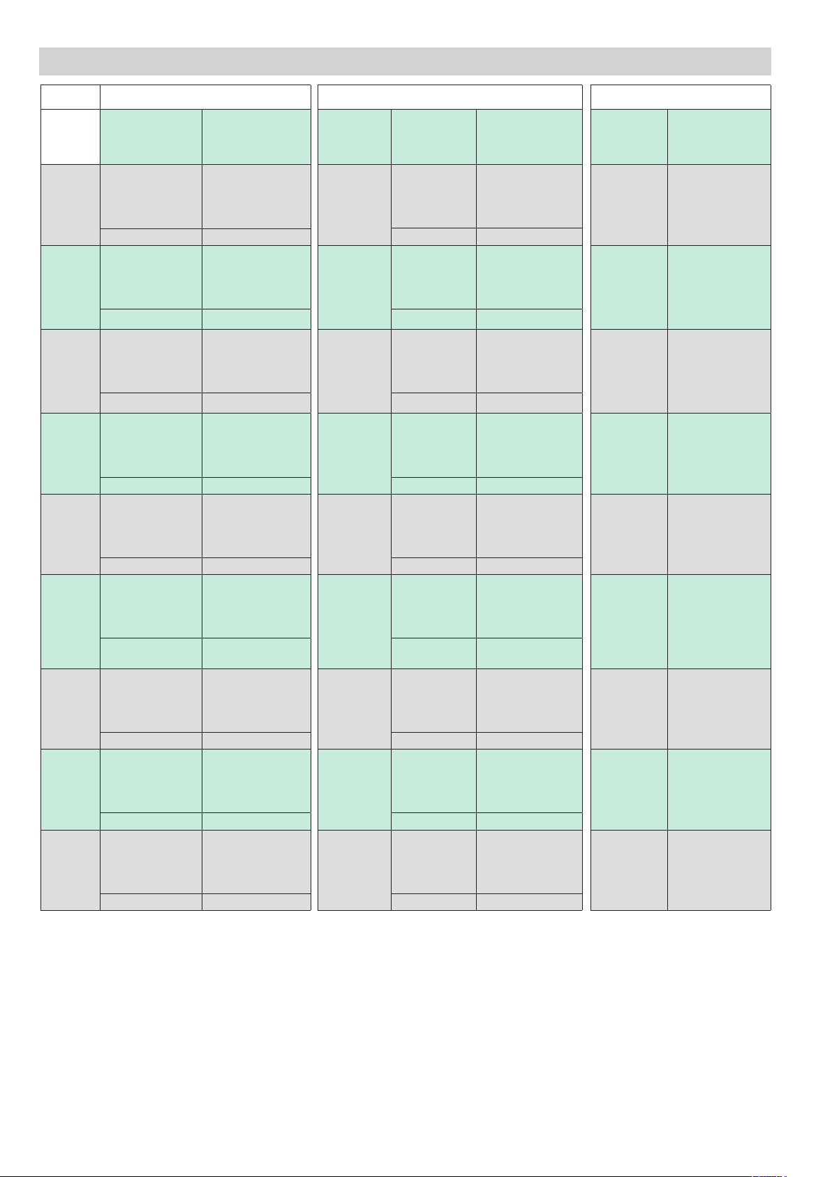
TABLE OF TERMINALS AND CONDUCTORS
Size
15A
25A
30A
40A
50A
60A
75A
90A
120A
CONTROL TERMINAL POWER TERMINAL
Type of
connection
Rigid/flexible/cable
lug conductor cross
section
Stripping length 8 mm
Rigid/flexible/cable
lug conductor cross
section
Stripping length 8 mm Stripping length 11 mm
Rigid/flexible/cable
lug conductor cross
section
Stripping length 8 mm Stripping length 11 mm
Rigid/flexible/cable
lug conductor cross
section
Stripping length 8 mm Stripping length 11 mm
Rigid/flexible/cable
lug conductor cross
section
Stripping length 8 mm Stripping length 11 mm
Rigid/flexible/cable
lug conductor cross
section
Stripping length 8 mm Stripping length 11 mm
Rigid/flexible/cable
lug conductor cross
section
Stripping length 8 mm Stripping length 11 mm
Rigid/flexible/cable
lug conductor cross
section
Stripping length 8 mm Stripping length 13 mm
Rigid/flexible/cable
lug conductor cross
section
Stripping length 8 mm Stripping length 13 mm
Conductor section /
Stripping length
0,2 - 1,5 mm2
24 - 16 AWG
0,2 - 1,5 mm2
24 - 16 AWG
0,2 - 1,5 mm2
24 - 16 AWG
0,2 - 1,5 mm2
24 - 16 AWG
0,2 - 1,5 mm2
24 - 16 AWG
0,2 - 1,5 mm2
24 - 16 AWG
0,2 - 1,5 mm2
24 - 16 AWG
0,2 - 1,5 mm2
24 - 16 AWG
0,2 - 1,5 mm2
24 - 16 AWG
Contact area
(WxD)
screw type
9,2 x 8 mm
M5
9,2 x 8 mm
M5
9,2 x 8 mm
M5
9,2 x 8 mm
M5
9,2 x 8 mm
M5
9,2 x 8 mm
M5
9,2 x 8 mm
M5
10,5 mm x
10,7 mm
M5
9,2 x 8 mm
M5
Type of
connection
Rigid/flexible/
ferrule conductor
cross section
Stripping length 11 mm
Rigid/flexible/
ferrule conductor
cross section
Rigid/flexible/
ferrule conductor
cross section
Rigid/flexible/
ferrule conductor
cross section
Rigid/flexible/
ferrule conductor
cross section
Rigid/flexible/
ferrule conductor
cross section
Rigid/flexible/
ferrule conductor
cross section
Rigid/flexible/
ferrule conductor
cross section
Rigid/flexible/
ferrule conductor
cross section
Maximum conductor
section /
Tightening torque /
Stripping length
25 mm2
3 AWG
2,5-3 Nm
(22-26,6lb-in)
25 mm2
3 AWG
2,5-3 Nm
(22-26,6lb-in)
25 mm2
3 AWG
2,5-3 Nm
(22-26,6lb-in)
25 mm2
3 AWG
2,5-3 Nm
(22-26,6lb-in)
25 mm2
3 AWG
2,5-3 Nm
(22-26,6lb-in)
25 mm2
3 AWG
2,5-3 Nm
(22-26,6lb-in)
25 mm2
3 AWG
2,5-3 Nm
(22-26,6lb-in)
50 mm2
1/0 AWG
2,5-3 Nm
(22-26,6lb-in)
50 mm2
1/0 AWG
2,5-3 Nm
(22-26,6lb-in)
GROUND TERMINAL •
Contact area
(WxD)
screw type
9 x 9 mm
M5
9 x 9 mm
M5
9 x 9 mm
M5
9 x 9 mm
M5
9 x 9 mm
M5
9 x 9 mm
M5
9 x 9 mm
M5
9 x 9 mm
M5
9 x 9 mm
M5
Tightening torque
1,5-2,5 Nm
(13.3 lb-in – 22 lb-in)
1,5-2,5 Nm
(13.3 lb-in – 22 lb-in)
1,5-2,5 Nm
(13.3 lb-in – 22 lb-in)
1,5-2,5 Nm
(13.3 lb-in – 22 lb-in)
1,5-2,5 Nm
(13.3 lb-in – 22 lb-in)
1,5-2,5 Nm
(13.3 lb-in – 22 lb-in)
1,5-2,5 Nm
(13.3 lb-in – 22 lb-in)
1,5-2,5 Nm
(13.3 lb-in – 22 lb-in)
1,5-2,5 Nm
(13.3 lb-in – 22 lb-in)
(*) Use of eyelet terminals is required for ground termination.
(WxD) = Width x depth
Page 15

EXTRARAPID FUSES
Model Fuse manufacturer Fuse Model size
GRS-H 15, GRS-H 15/48, GRS-H 15/60 Bussmann Div Cooper (UK) Ltd FWC16A10F 10x38
GRS-H 25, GRS-H 25/48, GRS-H 25/60 Bussmann Div Cooper (UK) Ltd FWC25A10F 10x38
GRS-H 30, GRS-H 30/48, GRS-H 30/60 Bussmann Div Cooper (UK) Ltd FWP40A14F 14x51
GRS-H 40, GRS-H 40/48, GRS-H 40/60 Bussmann Div Cooper (UK) Ltd FWP40A14F 14x51
GRS-H 50, GRS-H 50/48, GRS-H 50/60 Bussmann Div Cooper (UK) Ltd FWP63A22F 22x58
GRS-H 60, GRS-H 60/48, GRS-H 60/60, GRS-H 75,
GRS-H 75/48, GRS-H 75/60
GRS-H 90, GRS-H 90/48, GRS-H 90/60 Bussmann Div Cooper (UK) Ltd FWP100A22F 22x58
GRS-H 120, GRS-H 120/48, GRS-H 120/60 Bussmann International Inc. USA 170M1418 000-TN/80
FANS (for 90A/120A models only)
Model Code Type Supply
FAN60
FAN61
FAN62 363037 24 Vdc 60mm x 60mm x 25mm Separate power supply
FAN63 363037 24 Vdc 60mm x 60mm x 25mm Internally powered by GRS-H
363484 230 Vac 60mm x 60mm x 30mm for 90A models Separate power supply
363011 230Vac 80mm x 80mm x 38 mm for 120A models Separate power supply
363485 115Vac 60mm x 60mm x 30 mm for 90A models Separate power supply
363003 115Vac 80mm x 80mm x 38 mm for 120A models Separate power supply
Bussmann Div Cooper (UK) Ltd FWP80A22F 22x58
PERIODIC CLEANING
Every 6-12 months (depending on dust in the place where it is installed), blow a jet of compressed air downward through the cooling heatsink (on the opposite side of the fan).
In this way both the heat sink and the cooling fan are cleaned.
IN THE EVENT OF OVERTEMPERATURE ALARM
If periodic cleaning does not eliminate the problem, perform the following operations:
1. Disconnect the fan cables from the terminal block (if present) or disconnect the fan connector from the GRS-H (FAN63).
2. Unscrew the screws securing the fan to the support brackets
3. Check the condition of the fan, clean it or replace it
4. Reassemble the fan
Page 16

FANS (for 90A/120A models only)
Caution: make sure that the arrow showing the direction of the air flow on the fan is pointing toward the heat sink
1
2
3
Use a Phillips screwdriver with a max. diameter of 3.5mm.
Page 17

DERATING CURVES
Derating curves GRS-H 15 ÷ 30A
Ambient temperature [ºC]
Voltage load [A]
Derating curves GRS-H 40 ÷ 60A
Ambient temperature [ºC]
Voltage load [A]
Derating curves GRS-H 75 ÷ 120A
Ambient temperature [ºC]
Voltage load [A]
Caution: make sure that the arrow showing the direction of the air flow on the fan is pointing toward the heat sink.
DERATING CURVES GRS-H 15 ÷ 30A
DERATING CURVES GRS-H 40 ÷ 60A
Rated current curves as a function of ambient temperature (minimum distance between GRS-H of 20mm).
DERATING CURVES GRS-H 75 ÷ 120A
N.B: The curves of the GRS-H 90/120 refer to the device complete with a working specified fan.
Page 18

DOWNGRADE WITH INSTALLATION DISTANCE
Derating curves GRS-H 15 ÷ 30A
Distance [mm]
Voltage load [A]
Derating curves GRS-H 40 ÷ 60A
Distance [mm]
Voltage load [A]
Derating curves GRS-H 40 ÷ 60A
Distance [mm]
Voltage load [A]
Rated current curves as a function of the horizontal distance between the GRS-Hs (ambient temperature 40 °C).
DERATING CURVES GRS-H 15 ÷ 30A
DERATING CURVES GRS-H 40 ÷ 60A
Rated current curves as a function of the horizontal distance between the GRS-Hs (ambient temperature 40 °C).
DERATING CURVES GRS-H 75 ÷ 120A
N.B: The curves of the GRS-H 90/120 refer to the device complete with a working standard fan.
Page 19

ORDER CODE
Rated current
15Aac 15
25Aac 25
30Aac 30
40Aac 40
50Aac 50
60Aac 60
75Aac 75
90Aac 90
120Aac 120
Rated voltage V
480Vac 48
600Vac 60
Input type
6 ... 32 Vdc D
20 ... 260 Vac / Vdc A
GRS-H - - - - - - 0 - 0
0 None
0 Push In
FANS (for 90A/120A models only)
0 None
FAN60
FAN61
FAN62 24Vdc 60x60x25 mm
FAN63 24Vdc 60x60x25 mm (2)
230Vac 60x60x30 mm for 90A models
230Vac 80x80x38 mm for 120A models
115Vac 60x60x30 mm for 90A models
115Vac 80x80x38 mm for 120A models
0 None
Thermal alarm and load interrupted
1
Insulated contact ( NO ) (1)
Thermal alarm and load interrupted
2
Insulated contact ( NC ) (1)
Thermal alarm and load interrupted
3
Digital output PNP ( NO ) (1)
Thermal alarm
5
Insulated contact ( NC )
Future developments
Control terminal
OPTIONS
Notes:
(1) Not available for Type A input versions
(2) Module-powered fan, available for Type D input and option versions.
This option allows you to turn the fan on only when necessary, increasing its useful life.
Page 20

WARNINGS
WARNING: this symbol indicates danger.
Read the following warnings before installing, connecting or using the device:
• follow instructions precisely when connecting the device.
• always use cables that are suitable for the voltage and current levels indicated in the technical specifications.
• In applications with risk of damage to persons, machines or materials, you MUST install auxiliary alarm devices.
It is advisable to verify frequently that the alarm device is functional even during the normal operation of the equipment.
• DO NOT operate the device in rooms with dangerous (inflammable or explosive) atmosphere.
• During continuous operation, the heat sink can reach up to 100°C, and stays at a high temperature even after the device is turned off due to
thermal inertia; therefore, DO NOT touch it and avoid contact with electrical wires.
• do not work on the power part without first disconnecting electrical power to the panel.
• do not remove the cover when the device is powered!
Installation:
• correctly ground the device using the specific terminal.
• power supply lines must be separated from device input and output lines; always check that the supply voltage matches the voltage indicated
on the device label.
• avoid dust, humidity, corrosive gases and heat sources.
• respect the installation distances between one device and another (to allow for dissipation of generated heat).
• to keep air in movement, we advise you to install a fan near the GRS-H group in the electrical panel containing the GRS-H.
• respect the indicated dissipation curves
Maintenance: at regular intervals, check operation of the cooling fans and clean all air ventilation filters.
• repairs must be done out only by trained and specialized personnel. Cut power to the device before accessing internal parts.
• do not clean the box with solvents derived from hydrocarbons (trichloroethylene, gasoline, etc.). Using such solvents will compromise the
device’s mechanical reliability. Use a clean cloth moistened with ethyl alcohol or water to clean external parts in plastic.
Service: GEFRAN has a service department. The warranty excludes defects caused by any use not conforming to these instructions.
GEFRAN spa reserves the right to make aesthetic or functional changes at any time and without notice.
This device conforms to European Union Directive 2014/30/EU and 2014/35/EU as amended with reference to generic
standards: EN 61000-6-2 (immunity in industrial environment) EN 61000-6-4 (emission in industrial environment) EN 61010-1 (safety regulations).
DTS_GRS-H_07-2020_ENG
 Loading...