

Page 1
Main applications
• Packaging Machinery
• Thermoforming
• Plastic extrusion lines
• Industrial ovens and
furnaces
• Control application with
high switching speed
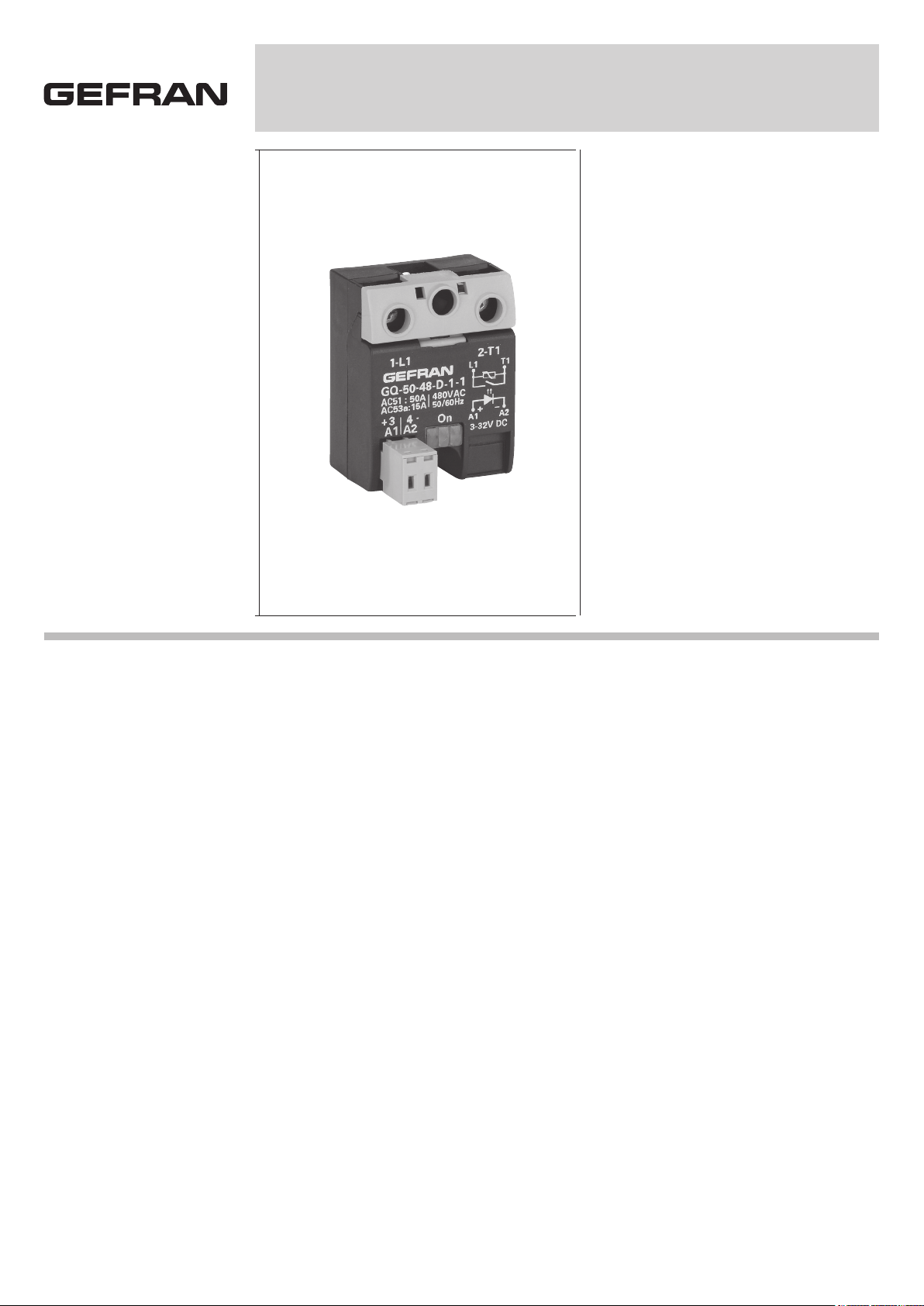
GQ 15 / 25 / 50 / 90 A
SINGLE PHASE SOLID STATE RELAYS
Main features
• Alternating current solid state relay
• Zero crossing switching
• Copper/semiconductor coupling
technology
• 15, 25, 50 and 90Arms nominal
current
• Non-repetitive voltage: up to
1600Vp
• Nominal Voltage: up to 600 Vac
• Control voltage : 3...32Vcc and
20...260Vac/Vcc with connector
• Isolation ((input-output)
4000Vrms
• Red LED drive active signal
• Internal MOV (option)
PROFILE
Zero crossing relay with antiparallel thyristor output is the most used solid state
relay in industrial applications.
In fact, it can be used for resistive, inductive and capacity loads.
“Zero crossing” relay is energised when
voltage meets the zero point and disenergised when current meets the zero point,
depending on the signal control on the
input circuit.
This relay has been designed to stand
high-value transitory applications .
When the relay has to stand high currents
for a long period, it is necessary to grant a
proper dissipation and an adequate electrical connection between relay terminals
and the load.
Varistors, fuses, thermostats and fans are
available as fittings.
Use the relay with an opportune heatsink
(see section accessories).
TECHNICAL DATA
General features
Rated frequency: 45...65Hz
Activation time:
GQ...-D- ≤1/2 cicle GQ...-A- ≤1 cicle
Deactivation time:
GQ...-D- ≤1/2 cicle GQ...-A- ≤1 cicle
Power factor: ≥0,5
Protection level: IP20
• U
= 4,8KV
imp
• Ui = 660V
• Overload current profile = 10
• Conditional short circuit current = 5KA
with type 1 coordination and respective
fuse protections.
GQ15/25 fuse type aM6A
GQ50 fuse type aM16A
GQ90 fuse type aM20A
GQ...- 24-
Nominal voltage: 24...230 Vac
(max range 20...253Vac)
Non-repetitive voltage: ≥ 600 Vp
Zero switching voltage: ≤ 20V
GQ...- 48-
Nominal voltage: 48...480 Vac
(max range 40...528Vac)
Non-repetitive voltage: ≥ 1200 Vp
Zero switching voltage: ≤ 40 V
GQ...- 60-
Nominal voltage: 48...600 Vac
(max range 40...660Vac)
Non-repetitive voltage: ≥ 1200 Vp
Zero switching voltage: ≤ 40V
Control input A1 - A2
GQ...-D-
Control voltage: 3...32Vcc
Turn ON voltage: ≥ 2,7Vc.c
Turn OFF voltage: ≤ 1Vcc
Reverse voltage: < 36Vcc
Consumption: ≤ 13mA@32V
GQ...-A-
Control voltage: 20...260Vac/Vcc
Turn ON voltage: ≥ 15Vac/Vcc
Turn OFF voltage: ≤ 6Vac/Vcc
Consumption: ≤ 8mAac/cc@260Vac/Vcc
Series connection of control inputs: max.
no. GQ...-A in series = Vcontrol -10% / 20
Output L1 - T1
GQ - 15 -
Nominal current: AC51: 15Arms;
AC53A (*): 3Arms
Min load current: 0,1Arms
Repetitive overcurrent t=1 s: ≤ 35Arms
Non-repetitive overcurrent t=20ms:200Ap
Current drop at nominal voltage and frequencies: ≤ 8mArms
2
I
t for fusing t=1-10ms: ≤ 200A2s
Critical dl/dt: ≥ 100A/µs
Page 2
Voltage drop at nominal current: ≤1,45Vrms
Critical dV/dt off-state: ≥ 1000V/µs
Ith = 15A
GQ - 25 -
Nominal current :
AC51: 25Arms; AC53A (*): 5Arms
Min load current: 0,3Arms
Repetitive overcurrent t=1 s: ≤ 60Arms
Non-repetitive overcurrent t=20ms: 300Ap
Current drop at nominal voltage and frequencies: ≤ 8 mArms
2
I
t for fusing t=1-10ms: ≤ 450A2s
Critical dl/dt: ≥ 100A/µs
Voltage drop at nominal current: ≤ 1,45Vrms
Critical dV/dt off-state:≥ 1000V/µs
Ith = 25A
GQ - 50 -
Nominal current :
AC51: 50Arms; AC53A (*): 15Arms
Min load current: 0,3Arms
Repetitive overcurrent t=1 s: ≤ 125Arms
Non-repetitive overcurrent t=20ms: 600Ap
Current drop at nominal voltage and frequencies: ≤ 8mArms
2
I
t for fusing t=1-10ms: ≤ 1800A2s
Critical dl/dt: ≥ 100A/µs
Voltage drop at nominal current: ≤1,35Vrms
Critical dV/dt off-state: ≥ 1000V/µs
Ith = 50A
GQ - 50B -
(with high I
2
t fusing current)
Nominal current : AC51: 50Arms;
AC53A (*): 18Arms
Min load current: 0,4Arms
Repetitive overcurrent t=1 s: ≤ 140Arms
Non-repetitive overcurrent t=20ms: 1150Ap
Current drop at nominal voltage and frequencies: ≤ 10mArms
2
I
t for fusing t=1-10ms: ≤ 6600A2s
Critical dl/dt: ≥ 100A/µs
Voltage drop at nominal current: ≤1,2Vrms
Critical dV/dt off-state: ≥ 1000V/µs
Ith = 50A
GQ - 90 -
Nominal current AC51: 90Arms;
AC53A (*): 20Arms
Min load current: 0,5Arms
Repetitive overcurrent t=1 s: ≤ 150Arms
Non-repetitive overcurrent t=20ms: 1500 Ap
Current drop at nominal voltage and frequencies: ≤ 10mArms
2
I
t for fusing t=1-10ms: ≤ 11200A2s
Critical dl/dt: ≥ 100A/µs
Voltage drop at nominal current:≤ 1,35Vrms
Critical dV/dt off-state: ≥ 1000V/µs
Ith = 90A
(*) Only versions: GQ-XX-24-X-1
GQ-XX-48-X-1
Insulation
Nominal insulation voltage Input/output:
≥ 4000 Vac
Nominal insulation voltage Output/case:
≥ 2500 Vac
Insulation resistance Input/output: ≥ 10
Insulation resistance Output/case: ≥ 10
10
Ω
10
Ω
Insulation capacity Input/Output: ≤ 8pF
Insulation capacity Output/case: ≤ 100pF
Ambient conditions
• Ambient temeparure: -25...+80°C
• Storage Temperature: -55...+100°C
• Maximum relative humidity: 50% a 40°C
• Maximum installation height: 2000 slm
• Pollution level: 2
Thermal features
GQ - XX -
Junction Temperature: ≤ 125°C
Rth junction/ambient: ≤ 12 K/W
GQ - 15 - / GQ - 25 -
Rth junction/case: ≤ 1,25 K/W
GQ - 50 -
Rth junction/case: ≤ 0,65 K/W
GQ - 50B -
Rth junction/case: ≤ 0,33 K/W
GQ - 90 -
Rth junction/case: ≤ 0,3 K/W
Solid State Relay Dissipated Power
Calculation
Single phase state relay
Pd GQ .. 15/25 = 1,45 . Irms [W]
Pd GQ .. 50/90 = 1,35 . Irms [W]
Pd GQ .. 50B = 1,2 . Irms [W]
IRMS = single-phase load current
Heatsink Thermal Resistance
Calculation
Rth = (90°C - T.amb. max) / Pd
where Pd = dissipated power
Max. amb. T = max air temperature inside
the electrical cabinet.
Use a heatsink with thermal resistance
inferior to the calculated one (Rth).
Installation notes
The device must be protected by a high
speed fuse (accessory).
Applications with power solid state relays
must also have a switch to isolate the
power line.
Protect the solid state relay against overheating by using a heatsink (accessory).
The heatsink must be sized according to
room temperature and load current (see
technical data).
Heatsink installation procedure:
spread 1 gram of thermoconductive silicone paste (we recommend DOW CORNING
340) on the dissipative metal surfaces of
the module.
The surfaces must be clean and the thermoconductive paste must not contain any
impurities. As alternative it is also possible to use the slide SIL-GQ available as
accessory.
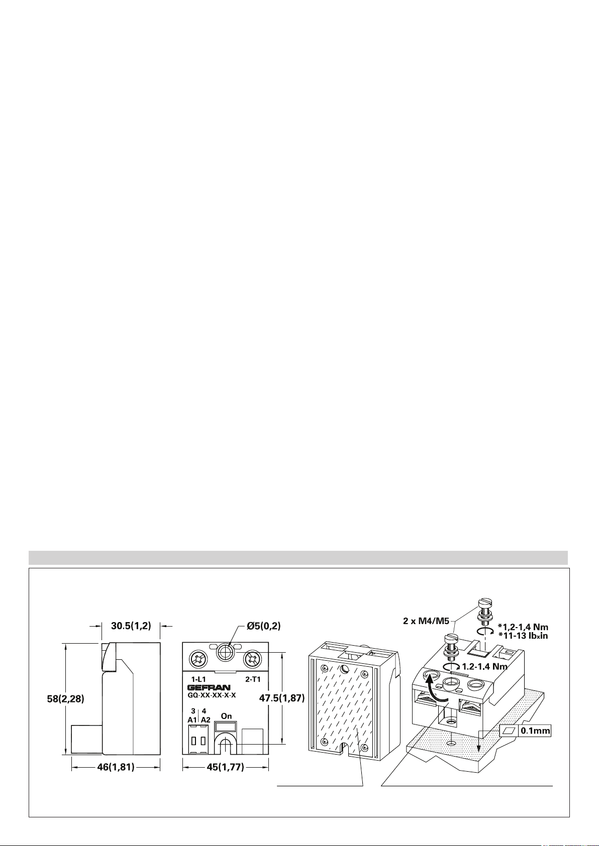
DIMENSIONS
Dimensions in mm, (inc)
*
30.5 (1.2) with option “command signal Terminal” = 4
*
(*) See installation notes
*Apply thermoconductive
paste
Raise the guard to access the
fastening hole or the terminals
Page 3

Alternately tighten the two fastening screws
3/A1+
4/A2-
Z.C.
Trigger
1/L1
2/T1
I limit.
(1)
(2)
3/A1
4/A2
Z.C.
Trigger
1/L1
2/T1
(1)
(2)
Functional Diagram
GQ-xx-xx-D-x-x
GQ-xx-xx-A-x-x
(1):
Only GQ-xx-60-x-1-x
(2):
Only GQ-xx-xx-x-1-x
until reaching a torque of 0.4…0.6 Nm.
Wait 5 minutes for any excess paste to
run off.
Alternately tighten the two fastening screws
until reaching a torque of 1.2…1.4 Nm.
ELECTRICAL CONNECTIONS
Attention
The contact surface of the heatsink module
may have a maximum planarity error of 0.1
mm and maximum roughness of 0.02 mm.
The fastening holes on the heatsink must
be threaded and countersunk.
The heatsink must be grounded.
Connection of 3-phase load and 2-phase control Connection of single-phase load
Heatsink (accessory)
Digital
output
on/off
Connection of 3-phase load with closed/open triangle or star
Relay
output
Page 4

TERMINALS AND LEADS: SPECIFICATIONS
Description
Power terminals
1-L1 2-T2
screw (M4)
Terminal type
contact area
(LxP) 13x11mm
2
2
2
Stripped
wire
1x2.5...6mm
2x1.5...2.5mm
2x2.5...6mm
Stripped 11mm
Prod
cable
Prod cable
with collar
1x1.5...6mm
2x1.5...2.5mm
2x2.5...6mm
1x1.5...10mm
2x1.5...2.5mm
2x2.5...6mm
Fork or eyelet cable 1x2.5...25mm
Locking torque
/
screwdriver type
slot 1x5...6mm
cross ø 5...6mm
2...2,4Nm
2
2
2
2
2
2
2
(#) When inserting two leads in the same terminal they must have the same cross-section
Note: The minimum and maximum sections
shown refer to unipolar copper wires isolated
in PVC.
with self-locking
spring
MORS1
1x0.2...2.5mm
2
2x0.5...0.75mm2 (#)
Stripped 10mm
1x0.2...1.5mm
2
2x0.2...0.75mm2 (#)
1x0.2...1.5mm
2
--- --- --- ---
with slot 0,6x3,5mm
for contact opening
thrust
Extractable 2 poles command terminals 3-A1 / 4-A2
with spring
with screw M3
double connection
MORS2
2x(1x0.2...2.5mm2)
2x(2x0.2...0.75mm2)(#)
Stripped 10mm
2x(1x0.25...2.5mm2)
2x(2x0.25...0.75mm2)
(#)
1x0.25...1.5mm
2
with slot 0,6x3,5mm
for contact opening
thrust (with flexible
stripped cable)
MORS3
1x0.25...2.5mm
2
2x0.25...1mm2 (#)
Stripped 7mm
1x0.25...2.5mm
2
2x0.25...1mm2 (#)
1x0.25...2.5mm
2
2x0.25...1.5mm2 (#)
with slot 0,6x3,5mm
with cross ø 3...3,8mm
0,5...0,6Nm
with screw M2.5
MORS4
1x0.5...1.5mm
2
Stripped 6mm
---
---
with slot
0.6x3.5mm 0.4Nm
FUSES/ FUSES HOLDER
HIGH SPEED FUSES FUSE HOLDER
Model
GQ15...
GQ25...
GQ50...
GQ90...
Model
GQ15...
GQ25...
Size
2
T
I
16A
2
S
150A
25A
390A2S
2
S
375A
50A
2
S
1800A
50A
2
S
1600A
80A
6600A2S
100A
2
S
12500A
GEFRAN HEATSINK
(see accessories)
Code
Format
FUS-016
10x38
FUS-025
10x38
FUS-026
14x51
FUS-051
14x51
FUS-050
22x58
FUS-080
22x58
FUS-100
22X58
DIS 25GD
DIS 50G
GQ50... DIS 50G Rth ≥ 0,83 K/W
GQ90... DIS 90G Rth ≥ 0,56 K/W
Data relating to 40°C ambient temperature, heatsink in vertical position with
15 cm of free air above and below.
Model
Code
FWC16A10F
338470
FWC25A10F
338474
FWC25A14F
338130
FWC50A14F
338079
FWC50A22F
338127
FWP80A22F
338199
FWP100A22F
338478
THERMAL
RESISTANCE
Rth ≥ 2,8 K/W
Rth ≥ 0,83 K/W
Dissipated
power @ In
Model Code
Approval
3,5W
PFI-10x38
337134
6W 13A
7W
UR 30A@690V
PFI-14x51
337503
9W 27A
UR 50A@600V
9,5W
Max power
dissipated
3W
5W
Max continuative
current
13A
18A
50A
PFI-22x58
14W 50A
337223
9,5W
UR 80A@600V
16W 60A
SECTION CABLEHEATSINK/ THERMAL RESISTANCE
Model Section
GQ15... 2,5mm
GQ25... 6mm
GQ50... 12mm
GQ90... 25mm
Minimum allowed rated section based on the rated currents of
the power solid state relays, for copper leads isolated in PVC in
continuous use and at room temperature of 40°C, according to
standards CEI 44-5, CEI 17-11, IEC 408 pursuant to standard
EN60204-1.
Power terminals in compliance with standard EN60947-1
2
2
2
2
Page 5

REFERENCE NORMS
Load Current Arms
GQ-15-xx-x-x-x
GQ-25-xx-x-x-x
Rth Heatsink °C/W
Load Current Arms
Ambient Temperature °C
Rth Heatsink °C/W
Load Current Arms
EMC Emission
EN 61000-6-4 Emissions conducted at radiofrequency Class A (Industrial devices)
EN 61000-6-4 Emissions irradiated at radiofrequency Class A (Industrial devices)
The product is designed for type A environments. Use of the product in type B environments may cause undesired electromagnetic
noise. In this case, the user should take appropriate steps for improvement.
EMC Immunity
EN 61000-6-2 Immunity for industrial environments
EN 61000-4-2 Electrostatic discharges 4kV by contact; 8 kV in air. Performance criterion 2.
EN 61000-4-6 Electromagnetic field at radiofrequency
0,15-80MHz
EN 61000-4-3 Electromagnetic field at radiofrequency
80-1000MHz
EN 61000-4-4 Immunity to burst LTest level 2kV/100 KHz. Performance criterion 2.
EN 61000-4-5 Immunity to surge Test level: 2kV (Phase-ground); 1kV (Phase-phase).
Safety
EN 61010-1 Safety requirements
Test level 3. Performance criterion 1.
Test level 10V/m. Performance criterion 1.
Performance criterion 2.
DISSIPATION CURVES
12.5
15
10
7.5
5
0
20 30 40 50 60 70
Ambient Temperature °C
GQ-50-xx-x-x-x
50
40
30
20
10
0
20 30 40 50 60 70
Ambient Temperature °C
3.40
4.00
4.60
5.70
7.50
0.52
0.66
0.83
1.50
2.50
25
20
15
Rth Heatsink °C/W
10
5
Load Current Arms
0
20 30 40 50 60 70
1.60
1.90
2.20
2.80
4.60
Ambient Temperature °C
GQ-50B-xx-x-x-x
50
40
30
Rth Heatsink °C/W
20
10
Load Current Arms
0
20 30 40 50 60 70
0.90
1.10
1.30
1.50
1.80
2.20
2.50
Ambient Temperature °C
GQ-90-xx-x-x-x
100
80
60
40
20
0
20 30 40 50 60 70
0.40
0.50
0.60
0.83
1.20
1.50
2.00
Rth Heatsink °C/W
Page 6

ORDER CODE
GQ
MODEL
GQ
NOMINAL CURRENT
15ACArms 15
25ACArms 25
50ACArms 50
50ACArms (*) 50B
90ACArms 90
NOMINAL VOLTAGE
CONNECTORS
0 Without connector
(MORS1) Two-pin spring
1
connector,enclosed
(MORS2) Two-pin double
2
spring connector, enclosed
(MORS3) Two-pin screw
3
connector, enclosed
(MORS4) Two-pin screw
4
connector, low profile
enclosed
230VACrms 24
480VACrms 48
600VACrms (**) 60
(*) Version with high I2t fusing current (short-circuit proof, using a specific
magnetothermic switch)
(**) Available only in versions GQ-XX-60-X-1-X (overloading protection
always present
Please, contact GEFRAN sales people for the codes availability
GEFRAN spa reserves the right to make any kind of design or functional modification at any moment without prior notice
OVERVOLTAGE PROTECTION
0 External
1
Internal
CONTROL VOLTAGE
D 3...32Vc.c.
A 20...260Vac/Vcc
•WARNINGS
WARNING: this symbol indicates danger.
Before installation, please read the following advices:
• follow the indications of the manual scrupulously when making the connections to the instrument.
• use a cable that is suitable for the ratings of voltage and current indicated in the technical specifications.
• if the instrument is used in applications where there is risk of injury to persons and damage to machines or materials, it is essential that it is used
with an auxiliary alarm device.
• It is advisable to verify frequently that the alarm device is functional even during the normal operation of the equipment.
• The instrument must NOT be used in environments where there could be the presence of dangerous atmospheres (inflammable or explosive)
• During continuous operation, the heatsink may reach 100°C and remain at a high temperature due to thermal inertia even after the device is
switched off. Therefore, DO NOT touch the heat sink or the electrical wires.
• do not operate on the power circuit untless the main supply is disconnected.
• DO NOT open the cover if device is “ON”!
Installation:
• connect the device to the ground using the proper ground terminal;
• the power supply wiring must be kept separate from that of inputs and outputs of the instrument; always check that the supply voltage corresponds
to that indicated on the instrument cover;
• keep away from dust, humidity, corrosive gases and heat sources;
• is recommended in the electrical panel containing the GQ, install a fan near the group of GQ that keep air in movement.
Maintenance
• Check the correct operation of the cooling fans at regular intervals; clean the ventilation air filters of the installation at regular intervals
• Repairs must be performed only by specialized or appropriately trained personnel. Cut off power to the device before accessing internal parts.
• Do not clean the box with solvents derived from hydrocarbons (trichloroethylene, gasoline, etc.).
Using such solvents will compromise the mechanical reliability of the device. To clean external plastic parts, use a clean cloth wet with ethyl
alcohol or water
Technical service:
GEFRAN has a technical service department. Defects caused by use not conforming to the instructions are excluded from the warranty.
UL
CSA
In conformity to ECC 2004/108/CE and 2006/95/CE and following modification with reference to standard EN 60947-4-2 (Low voltage equipment - AC Semiconductor starters and contactors)
In Conformity with UL508 - File: E243386
Conformity C/CSA/US CoFC no 70047999
DTS_GQ_12-2015_ENG
 Loading...