

Page 1
Main application
• Thermoforming
• Blowing
• Hot runners for injection presses
• Fiber weaving
• Heat treatment furnaces
• Wood-working machines
• Glass hardening furnaces
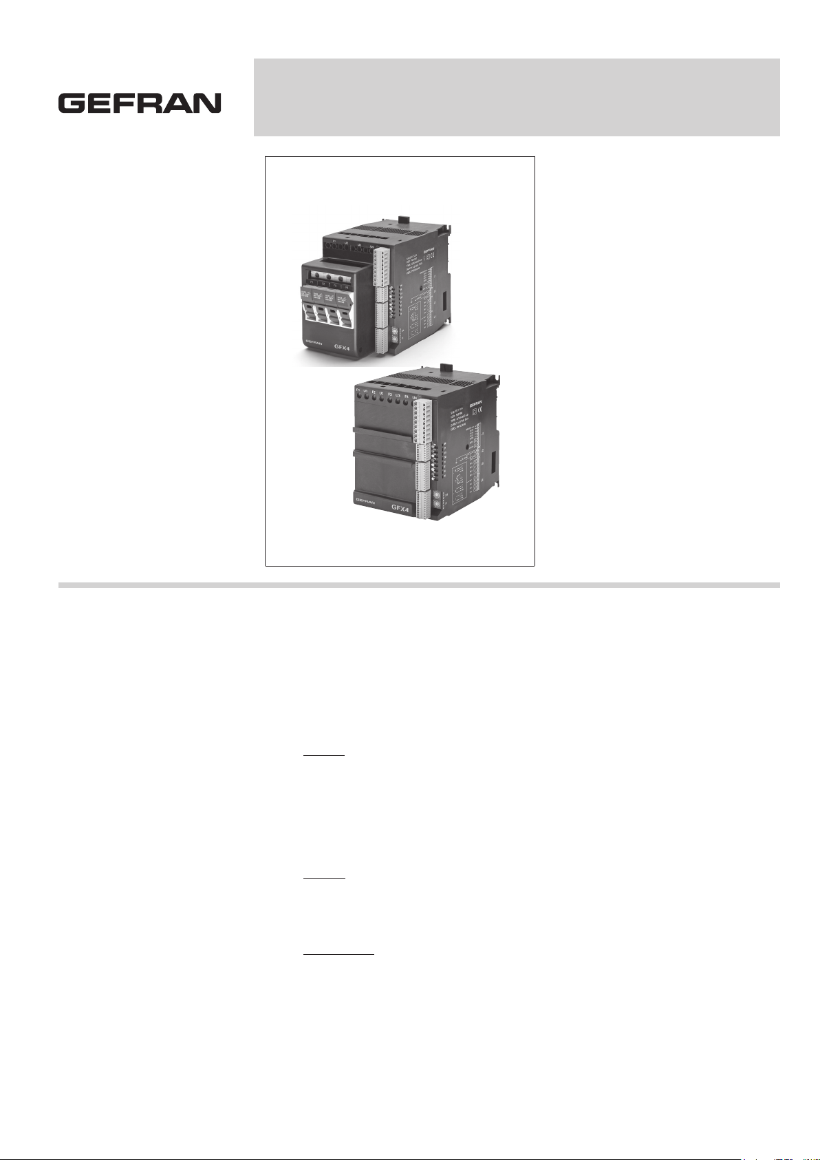
GFX4-IR
4-ZONE MODULAR POWER CONTROLLER FOR IR LAMPS AND INDUCTIVE LOADS
Main features
Stand-alone unit for independent control of
four electrical power control loops.
Extremely compact, with independent controls
and advanced diagnostics. Used to control
power for single-phase and 3-phase loads,
including high and low temperature coefficient
resistive loads, short wave infrared lamps and
transformer primaries.
Unit consisting of:
• Controller
• 30, 60, 80kW solid state relay
• Current transformers
• Fuses-holder (option)
• 4 universal main inputs
• 4 heat/cool independent PID
• 4 main output internally wired to the SSR
• 4 auxiliary analog inputs (option)
• 4 configurable output (option):
relay / logic / TRIAC / continuous
• 2 configurable relay alarm output
• 2 digital inputs
• Standard digital communication:
Modbus RTU
• Optional Fieldbus communication:
Profibus DP, CANopen, Euromap66,
DeviceNet, Modbus RTU, Modbus TCP,
Ethernet IP, EtherCAT, ProfiNET
• DIN rail or panel mounting
PROFILE
GFX4-IR is a four independent loop
controller, designed to manage electrical
power.
GFX4 is a compact unit encompassing
technological elements such as:
• controller
• solid state relay
• current transformers
• fuses-holders (option)
The final result is a cost saving in terms
of space and cabling.
The GFX4-IR is managed by a microprocessor that independently controls the
four control loops and also runs functions
specifically designed to manage singlephase and 3-phase loads, with low and
high temperature coefficient, medium and
short wave infrared lamps, control single
phase and 3-phase transformers (example, with loads such as Super Kanthal or
silicon carbide).
The multiple activation methods are all
software-configurable, and include:
- Zero crossing with constant cycle time
for conventional loads
- Burst firing with variable cycle time for
systems with low thermal inertia,
medium wave IR lamps
- Semi-Cycle for short wave IR lamps
with reduced flickering (half single cycle)
- Phase angle control with current limit for
short wave IR lamps, transformer primaries, with assignment of soft start and
soft stop options with limitation of max.
rms current.
GFX4IR runs complete diagnostics of current, voltage, and temperature levels:
Current
- Total and partial interrupted load alarm
- Function for self-learning of alarm thres hold for interrupted load
- SCR in short circuit alarm
- Unbalanced 3-phase line alarm
- Unbalanced 3-phase load alarm
Voltage
- Phase loss in case of 3-phase
configurations
- Check of correct phase sequence alarm
Temperature
- Overtemperature alarm
For complete load control in all applications, various feedback functions have
been developed:
- Voltage (V) feedback with maximum
voltage limit
- Current (I) feedback with maximum
current limit
- Power feedback with maximum power
limit
Configuration is changed by setting simple parameters with a software tool that
guides the user to a correct and safe
configuration.
GFX4-IR communicates with the operator
terminals according to the most popular
protocols: from the simple and efficient
Modbus to (via a second optional fieldbus
communication) the by-now indispensable Profibus DP, CANopen, DeviceNet,
Modbus RTU, Ethernet Modbus TCP,
Ethernet IP, EtherCAT, ProfiNET.
The product comes with a standard
configuration that is simple and quick to
modify, for example, to assign different
functions to outputs.
Page 2

MODELS
(see table in order code)
3 different sizes, depending on the electric power managed, are available.
GFX4-IR 80
Maximum contemporaneous power up to
80kW@480V.
Each zone can manage up to 19,2 kW.
This limit can be extend to 27,3 kW using
the “smart power management” (not all
the zone contemporaneous).
Nominal current 40A for zone, not contemporary maximum 57A.
GFX4-IR 60
Maximum contemporaneous power up to
60kW@480V.
Each zone could reach up to 15,3 kW.
Nominal current 32A for zone (UL30A).
Fuse holder could be provide as an
option.
GFX4-IR 30
Maximum contemporaneous power up to
30kW@480V.
Each zone could reach up to 7,6 kW.
Nominal current 16A for zone. Fuse holder could be provide as an option.
INPUTS
Process analogue
4 universal process input can accept:
- thermocouple
- thermoresistance
- linear current & voltage.
Input type can be selected by software,
no external devices are required.
Digital
2 digital input.
The function can be selected from a wide
range, including setpoint selection, MAN/
AUTO, alarm memory reset and many
other.
Incorporated CT
Four CTs are integrated in the product to
control currents delivered to each zone
and to manage the related alarms (HB...).
Auxiliary analogue (option)
4 further analogue inputs are available,
typically for external current transformer
reading.
OUTPUTS
A current transformer is furnished with
TRIAC output.
Alarms
Two relay outputs are available, configurable as minimum or maximum alarms.
LEDs
Eight monitoring led are available in order
to provide diagnostic information.
RN RUN state of the CPU
ER error
DI1 DI1 digital input state
DI2 DI2 digital input state
O1 Output 1 state
O2 Output 2 state
O3 Output 3 state
O4 Output 4 state
By default a different meaning is applicable.
POWER
The solid-state power unit (SSR) is integrated in the product. The SSR is built
with 4 pairs of SCR in antiparallel.
Configurable start-up modes
ZC - Zero Crossing constant cycle time
(settable in range 1-200sec)
BF - Burst Firing variable cycle time
(GTT)
HSC - Half Single Cycle corresponds to
Burst Firing that manages single
semi-cycles of conduction or stop
cycles
Useful for reducing flicker with
short wave IR loads (applied only
to single-phase load or 3-phase
open delta 6 leads)
PA - Phase Angle that manages the
firing angle.
Load type:
4 single-phase
3 independent single-phase in open delta
1 3-phase open delta, 6 leads
1 3-phase delta, 3 leads
1 3-phase star without neutral, 3 leads
1 3-phase star with neutral, 4 leads
.
FUSES (option)
The fuses are orderable on the GFX4-IR
30KW and 60kW model.
Thanks to this, you save time, wiring is
simplified, and dimensions in the panel
are reduced.
FUNCTIONS
Control
The Geflex control algorithm works with
any type of thermal process.
Different control modes are available:
from a simple ON/OFF control to PID single or double acting heat/cool (for cooling,
simply indicate the fluid used).
Sophisticated and efficient automatic
tuning algorithms for control parameters
provide precise process control without
the presence of an operator.
Alarms
There are 8 alarm assignable to each single channel or to all (AND / OR logic) and
configurable as absolute, relative, direct,
reverse, window, latching or not, inhibit at
power-on.
Diagnostics
Geflex assures efficient process monitoring from a thermal and electrical point
of view, allowing the operator to foresee
breakdowns or malfunctions and take
timely action (for example, in case the
temperature safety limit is exceeded, broken probe, load fault).
The LBA alarm precisely checks the control loop.
Current read (RMS)
• HB alarm load interrupted or partially
interrupted
• Calibration of HB alarm threshold via
automatic procedure starting from load
current level.
Alarm threshold is determined from
settable %
(ex.: if measured current =10A and
%=20, HB alarm threshold = 8A)
The procedure includes:
- start of requested power to maximum
- sampling of load current
- return to previous requested power
level for 3-phase load, three separate
alarm thresholds
• SCR in short circuit alarm
• Load in short circuit or overcurrent
alarm
• Unbalanced 3-phase load
Voltage read (RMS)
• Incorrect phase rotation diagnosis in
3-phase configuration.
• Phase loss alarm in 3-phase load
configuration
• Over temperature alarm
Output alarms configurable via software.
Heating control
For each zone, the heating control is
internally linked to the power output, no
other connections are necessary.
Cooling control (option)
For each zone, one of four types of cooling output is available:- relay, logic, triac
or continuous.
PROGRAMMING
The module is configured by setting simple parameters.
No knowledge of programming language
is required.
The module can be configured in various
ways:
• using GFX-OP
• using GF_eXpress tool software
• using Industrial PC or PLC.
The software can be used to define the
state of alarm outputs or a preset power
level to be supplied in case of broken
probe. This assures continuity of service
in the individual zone.
Tuning
• Self-tuning: calculation of PID parameters
at system start.
• Auto-tuning continuous:continuous
adjustment of PID
Page 3
• Autotuning one-shot: output modulation
and event-driven automatic PID parame ters re-calculation
Special functions
• Software Off: disabling of the control,
outputs are turned off.
• Inputs\outputs: direct management of
inputs/outputs, independently from
internal firmware.
• Simulation of four independent Geflex
units.
• Smart power management.
• Option:
- Soft start at timed power-on with or
without control of maximum current
reactivation after a settable shut-off
time.
- Current limit
- DT: Delay Triggering 0-90° on first
cycle (for inductive loads in modality
ZC or BF)
• Option for PA
- Soft start at timed power-on with or
without control of maximum current
reactivation after a settable shut-off
time.
- Soft stop at times power-off
• Feedback modes:
2
V or V
- Voltage feedback with maximum
voltage limit: controls by maintai ning constant voltage on the load
(proportional to P%_pid) regardless
of changes in line voltage
2
I or I
- Current feedback with maximum
current limit: controls by maintai ning constant current on the load
(proportional to P%_pid) regardless
of changes in line voltage or load
impedance
P
- Power feedback with maximum
power limit: controls by maintai ning constant power on the load
(proportional to P%_pid) regardless
of changes in line voltage or load
impedance.
You have to set the autocalibration parameter each time you change feedback
mode.
DIGITAL COMMUNICATION
The product is furnished with standard
digital communication [PORT 1] used as
GFX4 connection to a HMI or Industrial
PC.
Also by a dedicated connector (10 pins)
it’s possible to connect the actual range
of Gefllex.
A second standard digital communication
(PORT 2) configurable by most popular
protocol:
CANopen, Euromap66, DeviceNet,
Profibus DP, Modbus RTU Modbus TCP,
Ethernet IP, EtherCAT, ProfiNET is available as option.
Net address
Assigned by two rotative selectors.
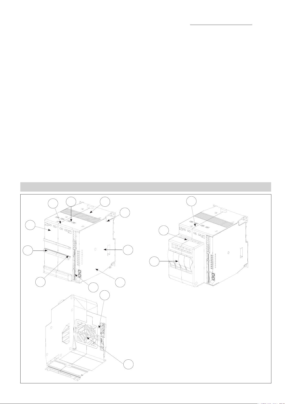
GENERAL DESCRIPTION
3
4
2
1
10
5
13
6
12
7
11
8
9
8
14
1. DIN rail frontal
2. power terminal: screws
3. power terminal
4. ventilation grid (do NOT obstruct)
5. hook/release device back DIN rail
6. hole for screws
7. configuration microswitches
8. standard digital communication
9. rotative selector switch
10. connectors J1, J2, J3, J4
11. fuses-holder (only for 30KW and 60KW models)
12. fuses-holder terminal (F1, F2, F3, F4/N)
13. power terminal (U1, U2, U3, U4)
14. ventilation grid (do NOT obstruct)
Page 4

Trigger modes
The GFX4-IR provides the following power control modes:
- modulation via variation of phase angle: PA modality
- modulation via variation of number of conduction cycles with “zero crossing” trigger”: ZC, BF, HSC modality.
PA - Phase angle
This mode manages power on the load by modulating load phase angle q
ex: if power to be transferred to the load is 100%, q = 180°
ex: if power to be transferred to the load is 50%, q = 90°
Zero Crossing mode
This function eliminates EMC noise. This mode controls power on the load via a series of conduction ON and non conduction OFF
cycles.
ZC - constant cycle time (Tc ≥ 1 sec, settable from 1 to 200 sec) Cycle time is divided into a series of conduction and non
conduction cycles in proportion to the power value to be transferred to the load.
For example, if Tc = 10sec, if the power value is 20% there is conduction for 2 sec (100 conduction cycles @ 50Hz) and non conduction for 8 sec (400 non conduction cycles @ 50Hz).
BF - variable cycle time (GTT)
This mode controls power on the load via a series of conduction ON and non conduction OFF cycles. The ratio of the number
of ON cycles to OFF cycles is proportional to the power value to be supplied to the load.
The CT repeat period is kept to a minimum for each power value (whereas in ZC mode the period is always fixed and not
optimized).
Example of operation in BF mode with power at 50%. A parameter defines the minimum number of conduction cycles
settable (from 1 to 10). In the example, this parameter = 2.
Page 5

HSC - Half single cycle
This mode corresponds to Burst Firing that includes single conduction cycles and half non-conduction cycles.
Example of operation in HSC mode
with power at 33 and 66%.
Softstart or Ramp at power-on
This type of start can be enabled in either phase control or pulse train mode.
With phase control, the increment of firing angle q stops at the corresponding power value to be transferred to the load.
The control of maximum current spike can be enabled during the ramp phase (this is useful in case of short circuit on the load or
loads with other temperature coefficients to automatically adjust the start time of the load).
The ramp is automatically re-enabled if the GFX4-IR remains off for a (settable) time.
Start ramp for resistive loads.
DT - “Delay triggering” of first cycle (only for control modes ZC, BF)
Settable from 0° to 90°.
Useful for inductive loads (transformer primaries) to prevent current spike that could in certain cases trip the high-speed
fuses that protect the SCRs.
Page 6

DIMENSIONS - INSTALLATION
101,54
42140
147
82
109,5
92,5 35 19,5
92,5 35 19,5
147
140
4
140
140
140
111,5
182
195
101,5
109,5
4132
132 4
TECHNICAL DATA
INPUTS
IN1...IN4 [process analog inputs]
Connector: J4
Function: default process variable (configurable)
Sampling time: 120msec the four inputs
Accuracy: 0,2% FS ±1 steps at 25°C.
(16000 points)
Thermal drift: 0,005% FS/°C
Type
• Thermocouples ITS90: J, K, R, S, T,
custom (IEC584-1, CEI EN 60584-1,
60584-2). Internal cold junction compensation with automatic compensation.
Selectable temperature range: °C/°F
• Thermoresistance: Pt100 DIN 43760
Max. resistance 20Ω
Selectable temperature range: °C/°F
• Voltage: range 0/12...60mV, Ri > 1MΩ
0/0,2…1V, Ri > 1MΩ custom 60mV at
32 sections
• Current: range 0/4...20mA, Ri = 50Ω
custom 20mA at 32 sections
IN5...IN8 [auxiliary analogue inputs]
Connector: J3
Function: default analog inputs reading
Sampling time: 480msec per TC, voltage
Accuracy: 1% FS ±1 steps at 25°C.
Type
• Thermocouple ITS90: J, K, R, S, T,
custom (IEC584-1, CEI EN 60584-1,
60584-2).
Internal cold junction compensation with
automatic compensation.
• Voltage: range 0/12...60mV, Ri > 1MΩ
Measurement of line Voltage and Current
• RMS current measurement function
Load current read; minimum measurable
current: 2A (30kW model), 4A (60kW
model), 6A (80kW model)
• Accuracy of RMS current measurement
2% f.s. at room temperature of 25°C in
ZC and BF firing modes; 3% f.s. in PA
mode with phase angle >90°, 10% f.s.
with phase angle <90°
• RMS voltage measurement function
Line voltage read; (acquisition of voltage values is valid for voltage in range
90...530VAC)
• Accuracy of RMS voltage measurement
1% f.s. with neutral connected; 3% f.s.
without neutral.
• Current and voltage sampling time
0.25 ms
DI1, DI2 [digital inputs]
Connector: J2
Function: default not enable (configurable)
Type
PNP, 24Vdc, 8mA (isol. 3500V)
Page 7

OUTPUTS
OUT 1...4 [heating control]
outputs connected to solid state relay
Function: default heating control (configurable)
OUT 5...8 [cooling control]
Connector: J1
Function: default cooling control (configurable)
Type
• Relay: NO, max 3A, 250V/30Vdc, cosj
= 1 resistive load
• Logic: 24Vdc, 35mA
• Continuous - voltage: 0/2...10V, ±10V,
max 25mA short circuit protection
- current: 0/4...20mA, 500Ω max
- insulation: 1500V
• Triac: 230V/4Amp AC5
(0,8A for four) (1,6A for two)
OUT 9...10 [alarms]
Connector: J1a/J1
Function: default alarms (configurable)
Type
Relay: NO, max 5A, /30Vdc, cosj = 1
LEDs
RN ...........RUN state of the CPU
ER ...........error
DI1 ...........DI1digital input state
DI2 ...........DI2digital input state
O1 ...........Out.1 main input state
O2 ...........Out.2 main input state
O3 ...........Out.3 main input state
O4 ...........Out.4 main input state
COMMUNICATION PORTS
PORT 1 [local bus]
Connectors: S1/S2/S3
Function: local bus
Protocol:
Modbus RTU
Baud Rate: 115Kbps (default) setting
1200...115Kbps
Node address: setting by double rotative selector
Connectors S1/S2: 2xRJ10 pins for flat
cable 4-4, RS485 2 wires insul. 1500V
Connectors S3: 10 pins for flat cable
PORT 2 [fieldbus]
Connectors: S4 / S5
Function: external fieldbus
Protocol:
Modbus RTU _________ 115Kbps
CANopen/Euromap 66 _ 10K...1Mbps
Profibus DP __________ 9,6...12Mbps
DeviceNet ___________
125K..500Kbps
Ethernet IP/Modbus TCP 10/100Mbps
EtherCAT ___________ 100Mbps
ProfiNET ____________ 100Mbps
See accessories
MICROSWITCHES
8 dip switches are available to select
wiring mode and different functionalities.
POWER
Load type
AC51
resistive or low-inductance loads
AC55b
short-wave infrared lamp (SWIR)
AC56a
ransformers, resistive loads with high
temperature coefficient
Switch-on modes
ZC
Zero crossing constant cycle time
(1-200sec)
BF
Burst Firing variable cycle time (GTT)
minimum or optimized
HSC
Half Single Cycle corresponds to Burst
Firing that manages Semi-cycles of on
and off. Useful to reduce flickering with
short-wave infrared loads
PA
Phase Angle
SSR [integrated power element]
Rated voltage: 480Vac
Work voltage range: 90...530Vac
Non-repetitive voltage: 1200Vp
Rated frequency: 50/60Hz self-adju-
sting
Rated current AC51 for zone
GFX4 30KW: 16A
GFX4 60KW: 32A
GFX4 80KW: 40A
(single channel 57A)
Rated current AC55b for zone
GFX4 30KW: 8A
GFX4 60KW: 16A
GFX4 80KW: 20A
for applications in which you can set a
minimum power output limit (ex: Lo.P
= 10%) by also limiting the lamp power
variation speed with gradient limit (ex:
G.out = 20%, PS.TM = 20s).
Under these conditions, the nominal
currents shown on the table can be
raised up to the values indicated for
AC51 type loads.
Rated current AC56b for zone
GFX4 30KW: 12A
GFX4 60KW: 25A
GFX4 80KW: 32A Trigger mode: ZC,
BF with DT (Delay Triggering), PA
with softstart
Non-repetitive overcurrent [t=20msec]
GFX4 30KW: 400A
GFX4 60KW: 600A
GFX4 80KW: 1150A
2
t per fusione [t=1...10msec]
I
GFX4 30KW: 645A
GFX4 60KW: 1010A
GFX4 80KW: 6600A
2
s
2
s
2
s
Dv/dt critical with deactivated output:
10,000V/ms High static dv/dt
Rated insulation voltage In/Out: 4000V
GENERAL FEATURES
Power supply: 24Vdc ±25%, max 8VA
Protection class: IP20
Working temperature range: 0...50°C
(see dissipation curves)
Storage temperature range: -20...+70°C
Relative humidity: 20...85% UR noncondensing
Installation: DIN EN50022 rail or panel
by screw
Dimensions: see dimensions and installation
Weight:
models 30/60/80: 1200g.
models 30/60 with fusesolder:1600g.
Page 8

ELECTRICAL CONNECTIONS
Triac Logic/continuous Relay
Load 1
Load 2
Load 3
Load 4
POWER SUPPLY
+24Vdc
c (OUT 5...8)
OUT 5
OUT 6
OUT 7
OUT 8
OUT 9
OUT 10
18...32Vdc
IN 5
IN 6
IN 7
IN 8
IN 1
IN 2
IN 3
1
no
no
no
no
c
no
c
no
6
J1a
9
Green
Red
Yellow
Yellow
Yellow
J1
9
1
J2
7
1
4
+VI
3
Tx/RxTx/Rx+
GNDI
+VI
Tx/RxTx/Rx+
GNDI
S1
S2
Port 1
2
1
4
3
2
1
S3
Yellow
Yellow
Yellow
J3
12
1
S4
Port 2
S5
J4
power
Model
max current
IN 4
Model without fuses-holder
30kW
16A
12
60kW
32A (30A)*
Model with fuses-holder
80kW
57A (40A)*
rigid
flexible
* UL certification
0,2 - 6mm
0,2 - 4mm
0,25 - 4mm
0,25 - 4mm
0,5 - 0,6Nm 0,5 - 0,6Nm 1,2 - 1,5Nm
2
2
24-10AWG
24-10AWG 0,2 - 4mm
2
23-10AWG 0,25 - 4mm
2
23-10AWG 0,25 - 4mm
0,2 - 6mm
2
2
24-10AWG 0,5 - 16mm
24-10AWG 0,5 - 10mm
2
23-10AWG 0,5 - 10mm
2
23-10AWG 0,5 - 10mm
2
2
2
2
20-6AWG
20-7AWG
20-7AWG
20-7AWG
Page 9

ORDER CODE
Model
GFX4
30
(4x16A)
60
(4x32A)
(4x30A)*
80
(4x40A)
Current
(Amp)
max
for channel
range nominal working
Voltage (Vac) Power (kW)
16 24...530 480
32 (30)* 24...530 480
40* 57 24...530 480
110
230
400
480
110
230
400
480
110
230
400
480
total
contemporary
(4x16x110)
7
(4x16x230
14,7
(4x16x400)
25,6
(4x16x480)
30,7
(4x32x110)
14
(4x32x230)
29,4
(4x32x400)
51,2
(4x32x480)
61,4
(4x40x110)
17,6
(4x40x230)
36,8
(4x40x400)
64
(4x40x480)
76,8
single
channel
(16x110)
1,7
(16x230)
3,6
(16x400)
6,4
(16x480)
7,6
(32x110)
3,5
(32x230)
7,3
(32x400)
12,8
(32x480)
15,3
(40x110)
4,4
(40x230)
9,2
(40x400)
16
(40x480)
19,2
max for
single channel
(1x16x110)
1,7
(1x16x230)
3,6
(16x400)
6,4
(1x16x480)
7,6
(32x110)
3,5
(1x32x230)
7,3
(1x32x400)
12,8
(1x32x480)
15,3
(1x57x110)
62,7
(1x57x230)
13,1
(1x57x400)
22,8
(1x57x480)
27,3
* Certification UL
NOMINAL POWER
30KW 30
60KW 60
80KW 80
AUXILIARY OUTPUTS
Absents O
Relay R
Logic D
Continuous C
Triac T
GFX4-IR
FIELDBUS
O Absent
M Modbus RTU
P Probus DP
C CANopen
C1 Euromap 66
D Device Net
E Ethernet Modbus TCP
E1 Ethernet IP
E2 EtherCAT
E4 ProNET
E5 Real Time Ethernet
FUSES
O Absent
F Fuses-holder + fuses extrarapid (*)
2 Absent
(*) Available only for 30, 60kW power
4 4 Linear inputs (**)
(**) Option NOT available with Fieldbus E1 or E2 or E4 or E5
GEFRAN spa reserves the right to make aesthetic or functional changes at any time and without notice.
AUXILIARY INPUTS
 Loading...