

gefran GF_VEDO TL Series, GF_VEDO TL 65CK, GF_VEDO TL 104CT, GF_VEDO TL 104CK, GF_VEDO TL 65CT Installation And Operation Manual
Page 1

1
80543B_MHW_GF_VEDO-TL_0109_ENG
GF_VEDO TL
Code 80543B / Edition 03 - 01/09
INSTALLATION AND
OPERATION MANUAL
GENERAL INDEX
page
Graphic symbols used 2
1 Preliminary instructions 3
General description 3
Preliminary warnings 3
2 Installation and Connection 4
Electrical power supply 4
Notes concerning electrical safety and
Electromagnetic compatibility 4
Instrument power supply 5
Inputs and outputs connection 5
Dimensions 6
Fixing 9
3 Technical Specifications 12
3.1 Display 12
3.2 CPU and Memory 12
3.3 Operative Systems 12
3.4 Bios 12
3.5 Integrated keyboard in CK versions 12
3.6 GF_VEDO TL user connections 13
3.6.1 Power supply port 14
3.6.2 Auto-start port
(optional) 15
3.6.3 Ethernet ports 15
3.6.4 RS-232 port 16
3.6.5 Optoisolated RS-485 port 16
3.6.6 Optoisolated CAN port
(optional) 17
3.6.7 USB ports 17
3.6.8 AUX port 17
3.6.9 Matrix Keyboard port
(Key & LED) 18
3.6.10 Mouse and Keyboard PS2 port 18
page
3.7 Access to internal system resources 19
3.7.1 DOM mass memory 19
3.7.2 System memory: SODIMM 19
3.7.3 Internal battery 20
4 Connection Examples 21
5 Summary of Characteristics 22
6 Technical-Commercial information 23
Order code 23
The contents of each section are summarized
immediately following the section heading
Page 2

2
80543B_MHW_GF_VEDO-TL_0109_ENG
Gefran S.p.A. All Rights Reserved
This manual is the sole property of GEFRAN S.p.A.
The information in this manual is reserved and confidential. No part of this manual may be reproduced, photocopied, transmitted, transcribed, or translated into other
languages, with computers or in any other way (electronic, mechanical, magnetic, optical, chemical, manual,
etc.) without explicit written permission from Gefran
S.p.A.
IMPORTANT
Although all of the information in this manual has been
carefully checked, Gefran S.p.A. assumes no liability
with regard to possible errors, or with regard to damage
to persons or property due to improper use of this
manual.
The same applies with regard to persons or companies
involved in the writing or production of this manual.
Gefran S.p.A. reserves the right to change the contents
and structure of this manual and to change product specifications at any time and without notice.
Gefran S.p.A. does not issue any type of guarantee with
regard to this manual, including but not limited to implicit
guarantees of marketability and suitability for a defined
purpose.
Gefran S.p.A. declines all liability with regard to the use
of its software on devices not supplied by Gefran S.p.A.
Windows™ is a registered trademark of Microsoft
Corporation.
PREFACE
This manual provides a detailed description of the main
technical data of the various versions of Gefran’s
GF_VEDO TL product.
The following information is indispensable for the correct use of the GF_VEDO TL: proper wiring, correct
jumper settings and the correct connection to external
devices.
Keep in mind that most of the hardware options can be
configured via software by means of the setup data stored in the eeprom. As a result, there are just a few
options solely for hardware, which significantly simplifies
configuration of the GF_VEDO TL.
Graphic symbols
Graphic symbols are used to differentiate among the types and importance of the information in these Instructions
and to facilitate the reader’s understanding.
Indicates the contents of the various sections of
the manual, general warnings, notes, and other
important points.
Indicates a particularly delicate situation that could
affect the safety or good operation of the product,
or an instruction that must absolutely be followed
in order to prevent hazardous situations.
Indicates a risk to the user’s safety due to the presence of high voltage at the specified points.
Indicates a suggestion (based on the experience
of GEFRAN Technical Personnel) that could be
very useful under certain circumstances.
Information of a general and applicative
nature.
Important notes for product safety and
reliability.
Indicates a reference to Detailed Technical
Documents available on GEFRAN’s website: www.gefran.com
Page 3

3
80543B_MHW_GF_VEDO-TL_0109_ENG
Preliminary warnings
Read the following preliminary warnings before
installing and using the GF_VEDO TL operator
terminals. Doing so makes start-up quicker
and lets you avoid some problems that might
be mistaken for malfunctions or limitations of
the terminal.
• Immediately after unpacking the product, make a note
of the order code and the other identification data given
on the label affixed to the outside of the container and
copy them to the table below.
These details must always be kept close at hand and
referred to the personnel involved in the event of help
from Gefran Customer Service Assistance.
• Check that the terminal is in perfect condition and was
not damaged during shipment. Make sure that the package also contains the fastening accessories and the
installation CD-ROM. Any inconsistencies, omissions or
evident signs of damage should be reported immediately
to your Gefran sales agent.
• Check that the order code corresponds with the configuration requested for the application the terminal is
needed for, referring to Section: “Technical - Commercial
Information”.
Example: GF_VEDO - 104CT - VW - C1 - S1 - G
• Model: GF_VEDO 104CT
• Operating system: Vx Works
• Expansion 1: CANopen
• Expansion 2: RS232 + AUC
• Lexan: Gefran
Consult the section “Installation and Connection” before
installing the terminal on the machine control panel or
host system Consult the section “Sales Information” for
the order code. Users and/or system integrators who
want more detailed information on serial communication
between standard PCs and/or Gefran Industrial PCs
and Gefran Programmable Instruments may access the
various Technical Reference Documents in PDF format
available on Gefran’s website: www.gefran.com.
In the event of presumed instrument malfunction, before
contacting Gefran Technical Service Assistance, refer to
the Troubleshooting Guide given in Section "Maintenance", and if necessary refer to the F.A.Q. Section (Frequently Asked Questions) on the Gefran Web Site
www.gefran.com
SN: ......................... (Serial no.)
CODE: ......................... (Finished product code)
TYPE: ......................... (Order Code)
SUPPLY: ......................... (Type of electrical power supply)
VERS: ......................... (Software version)
1 • PRELIMINARY INSTRUCTIONS
This section contains information and warnings of a general nature which should be read before proceeding with controller installation, configuration and use.
General description
The GF_VEDO TL operator terminal line is a compact
and low-cost solution for machine control.
A single product integrates machine cycle control
[SoftPLC] and graphic page display [SCADA], allowing
quick and low-cost creation of many automation solutions.
The GF_VEDO TL terminals create the machine/operator interface by means of LCD monitor, touch-screen,
and a wide variety of peripheral I/Os.
GF_VEDO TL terminals are applied mainly to machine
control for packaging, metals, wood and plastic applications. This Installation Guide describes the main characteristics of the operator panels and refers to the following models:
GF_VEDO TL 65CT Operator interface with 6.5” LCD TFT color display
GF_VEDO TL 65CK Operator interface with 6.5” LCD TFT color display and integrated
47-key keyboard
GF_VEDO TL 104CT Operator interface with 10.4” LCD TFT color display
GF_VEDO TL 104CK Operator interface with 10.4” LCDTFT color display and integrated
54-key keyboard
Page 4

4
80543B_MHW_GF_VEDO-TL_0109_ENG
2 • INSTALLATION AND CONNECTION
This section contains the instructions necessary
for correct installation of the GF_VEDO TL into
the machine control panel or the host system
and for correct connection of the controller
power supply, inputs, outputs and interfaces.
Before proceeding with installation read the
following warnings carefully!
Remember that lack of observation of these
warnings could lead to problems of electrical
safety and electromagnetic compatibility, as
well as invalidating the warranty..
Electrical power supply
• the GF_VEDO TL is NOT equipped with an On/Off
switch: the user must provide a two-phase
disconnecting switch that conforms to the required
safety standards (CE marking), to cut off the power
supply upstream of the terminal.
The switch must be located in the immediate vicinity of
the terminal and must be within easy reach of the
operator.
One switch may control more than one terminal
• if the terminal is connected to NOT isolated electrical
equipment (e.g. thermocouples), the earth connection
must be made with a specific conductor to prevent the
connection itself from coming directly through the
machine structure.
• if the GF_VEDO TL is used in applications with risk of
damage to persons, machinery or materials, it is
essential to connect it up to auxiliary alarm
equipment. It is advisable to make sure that alarm
signals are also triggered during normal operation.
The terminal must NOT be installed in flammable or
explosive environments; it may be connected to
equipment operating in such atmospheres only by
means of appropriate and adequate types of
interface, conforming to the applicable safety
standards.
Notes Concerning Electrical Safety and
Electromagnetic Compatibility:
CE MARKING: EMC Conformity (electromagnetic
compatibility)
in accordance with EEC Directive 2004/108/CE.
GF_VEDO TL series are mainly designed to operate in
industrial environments, installed on the switch boards
or control panels of productive process machines or
plants. As regards electromagnetic compatibility, the
strictest generic standards have been adopted, as indicated in the table below.
BT Conformity (low voltage) in accordance with
Directive 2006/95/CE.
EMC conformity has been tested with the following
connections.
Generic standards emission standard
for industrial environment
Emission enclosure
EN 61000-6-4
CISPR-11
Generic norm
Class A
EMC EMISSION
EMC IMMUNITY
Programmable controllers
ESD immunity
RF interference immunity
Radiofrequency interference
Burst immunity
Pulse immunity
Magnetic fields immunity
Voltage dips, short interruptions and voltage immunity tests
EN 61131-2
EN 61000-4-2
EN 61000-4-3
EN 61000-4-6
EN 61000-4-4
EN 61000-4-5
EN 61000-4-8
EN 61000-4-11
Product standard
± 4 kV contact discharge
± 8 kV air discharge
10 V/m amplitude modulated
80 MHz-1 GHz
10 V/m amplitude modulated
1.4 GHz-2 GHz
3 V/m amplitude modulated
0.15 MHz-80 MHz
± 2 kV power line
± 1 kV signal line
0,5 kV common mode
100 A/m
100%U, 10ms
Low voltage directive safety EN 61010-1
Installation category II and
pollution degree 2
LOW VOLTAGE DIRECTIVE SAFETY
Table 1 - EMC Emission
Table 2 - EMC Immunity
Table 3 - LVD Safety
Page 5

5
80543B_MHW_GF_VEDO-TL_0109_ENG
Instrument power supply
• The power supply to the electronic equipment on the
switchboards must always come directly from an
isolation device with a fuse for the instrument part.
• The electronic instruments and electromechanical
power devices such as relays, contactors, solenoid
valves, etc., must always be powered by separate
lines.
• When the electronic instrument power supply is
strongly disturbed by voltage problems from power
units or motors, an isolation transformer should be
used for the controllers only, earthing the screen.
• It is essential that the plant has a good earth
connection:
- the voltage between neutral and earth must not be >1V
- the resistance must be < 6Ω;
• If the mains voltage fluctuates strongly, use a voltage
stabilizer.
• In the proximity of high frequency generators or arc
welders, use adequate mains filters.
• The power supply lines must be separate from the
instrument input and output ones.
Inputs and outputs connection
• To connect the analogue inputs, strain gauge,
linear, (TC, RTD) the following is necessary:
- physically separate the input cables from those of the
power supply , the outputs and the power connections.
- use woven and screened cables, with the screen
earthed in one point only.
• To connect the control outputs, alarm(contactors,
solenoid valves, motors, fans, etc.), fit RC groups
(resistance and condensers in series) in parallel to
the inductive loads that operate in Alternating
Current.
(Note: all the condensers must conform to VDE
(class X2) standards and withstand a voltage of at
least 220V AC. The resistances must be at least 2W).
• Fit a 1N4007 diode in parallel with the coil of the
inductive loads that operate in Direct Current.
GEFRAN S.p.A. declines all responsibility for
any damage to persons or property caused
by tampering, neglect, improper use or any
use which does not conform to the characteristics of the controller and to the indications given in these Instructions for Use.
Prescription UL
- Operating surrounding air temperature rating of 50°C
- For use on a flat surface of a type 1 enclosure
Page 6

6
80543B_MHW_GF_VEDO-TL_0109_ENG
Dimensions
All measurements are expressed in mm, with tolerance of ± 0.5.
GF_VEDO TL 65CT dimensions
179,5
187
127133
115 67
177,5
166
125
74,5
Fig. 1 - Dimensions and cut-out GF_VEDO TL 65CT
Fig. 2 - Dimensions and cut-out GF_VEDO TL 65CK
180
222
187
230
115
68
8
220
1025
35
5
6
1785
6
166
GF_VEDO TL 65CK dimensions
Page 7

7
80543B_MHW_GF_VEDO-TL_0109_ENG
GF_VEDO TL 104CT dimensions
Fig. 3 - Dimensions and cut-out GF_VEDO TL 104CT
258
184
166
266
115
182,5
61
256
68,5
192,5
Page 8

8
80543B_MHW_GF_VEDO-TL_0109_ENG
Fig. 4 - Dimensions and cut-out GF_VEDO TL 104CK
GF_VEDO TL 104CK dimensions
258
281
68
266
289
115
8
120
5 279
44 5
52565
16645 45
Page 9

9
80543B_MHW_GF_VEDO-TL_0109_ENG
Fixing
Panel mounting of GF_VEDO TL
GF_VEDO TL panels are designed for front panel installation.
After making the opening shown on the template drawing, fasten the GF_VEDO TL with the blocks required and
supplied with the product.
Fig. 5 - Panel mounting GF_VEDO TL 65CT
Fig. 6 - Panel mounting GF_VEDO TL 65CK
Page 10

10
80543B_MHW_GF_VEDO-TL_0109_ENG
Fig. 7 - Panel mounting GF_VEDO TL 104CT
Fig. 8 - Panel mounting GF_VEDO TL 104CK
Page 11

11
80543B_MHW_GF_VEDO-TL_0109_ENG
If protection against water is necessary, it is essential to do as follows when installing the panel:
• make the edges of the hole for the panel perfectly smooth and flat
• tighten each fastening screw (or nut) until the corner of the frame touches the panel
• the panel hole must have the dimensions specified in this manual
The GF_VEDO TL terminals also have an O-Ring inserted at the rear of the display frames, as shown in Figure 9.
Fig. 9 - O-Ring on GF_VEDO TL terminals
Cleaning the device
Clean the device only with a soft cloth and non-abrasive neutral soap. Do not use solvents.
Page 12

12
80543B_MHW_GF_VEDO-TL_0109_ENG
3 • TECHNICAL SPECIFICATIONS
Table 14 shows the main technical characteristics of each GF_VEDO TL version.
In particular, it shows characteristics for displays, processors, storage devices and interfaces.
3.5 Integrated keyboard in CK versions
The CK versions of GF_VEDO TL terminals have an integrated keyboard at the bottom of the display.
The keyboard has 15 (GF_VEDO TL 65CK) or 22 (GF_VEDO TL 104CK) function keys and 32 keys for entering
alphanumeric characters.
Fig. 10 - Integrated keyboard on GF_VEDO TL 65CK terminals
3.1 Displays
The various GF_VEDO TL versions have LCD - TFT (Thick Film Transistor) color displays measuring 6.5” or 10.4”,
as shown in Table 14.
3.2 CPUs and Memories
GF_VEDO TL terminals are equipped with GEODE SC1200 processors.
Mass memory devices such as DOM (Disk On Module) and DRAM memory systems suitable for the operating
system can also be installed on the terminals. The terminal has 2 MB of static RAM.
3.3 Supported Operating Systems
GF_VEDO TL terminals offer the user various types of operating systems:
• VxW
orks: a real-time operating system by Wind River System.
Just like most real-time operating systems, VxWorks includes a multitasking kernel with optional scheduling and
rapid interrupt response.
• Windows XP Embedded: the modular version of Microsoft Windows XP Professional.
3.4 Bios
The Bios supplied for GF_VEDO TL terminals is Embedded BIOS® 2000 by General Software.
Page 13

13
80543B_MHW_GF_VEDO-TL_0109_ENG
Fig. 12 - GF_VEDO TL connector
Name Description
CAN CAN layer2
RS232 RS-232 serial
MOUSE PS/2 mouse (green)
PC-KEY PS/2 keyboard (violet)
USB USB 1.1 Host (500mA)
ETH1 Ethernet 10/100 Base-T
ETH2 Ethernet 10/100 Base-T
KEY & LED Fieldbuses keyboard
RS485 Optoisolated RS-485 serial
AUTO START Auto power-on
24VDC Power supply
AUX Auxiliary (options)
PC-KEY AUX Auxiliary PS/2 keyboard
Table 4 - GF_VEDO TL connector description
Fig. 11 - Integrated keyboard on GF_VEDOTL 104CK terminals
3.6 GF_VEDO TL user connections
The user connections specified on Table 14 are made at the bottom by means of Gefran standard and custom connectors.
Page 14

14
80543B_MHW_GF_VEDO-TL_0109_ENG
3.6.1 Power supply port
Power supply: 24VDC ±25%. The internal power supply is galvanically isolated and protected against polarity reverses and short circuits by a resettable fuse. The panel has a power terminal. The connector diagram is shown in
Figure 13.
Note:
check that the power supply is able to deliver the power needed for correct operation of the device.
The device must always be grounded. Grounding helps limit the effects of electromagnetic noise on the control
system. All electronic devices of the control system must be grounded. Ground the devices in a manner conforming
to applicable standards and regulations.
Fig. 13 - GF_VEDO TL power supply/auto power-on connector
Pin Description
1 Power supply common
2 Auto power-on output
3 Ground
4 Auto power-on common
5 Power supply +24Vdc
6 Power supply Auto power-on
Table 5 - Assignment of signals to Power Supply/Autostart connector of GF_VEDO TL terminals
To limit susceptibility to noise, you have to install an electromagnetic emission suppression core as shown in Figure
14. This component, supplied with the product, is a ferrite core coated in plastic for round section wires.
642
+
-
531
Fig. 14 - Inserting cores in the power supply lines of GF_VEDO terminals
135
2
4
6
531
642
GND
+24Vcc ±20%
2A max
+24V
Page 15

15
80543B_MHW_GF_VEDO-TL_0109_ENG
3.6.2 Autostart Port
GF_VEDO TL uses the optional Autostart output to activate an external relay by means of a programmable internal
timer. Activation requires that only the relay be powered, and to run the external devices you have to use the free
contact of the relay (activation time approx. 10 seconds).
We recommend the use of 24VDC relays with a maximum of 100mA at the coil.
1
8
Fig. 16
GF_VEDO TL Ethernet port connector
Pin Name Description
1 TX_D+ Tranceive data +
2 TX_D- Tranceive data 3 RX_D+ Receive data +
4 N.C. Not connected
5 N.C. Not connected
6 RX_D- Receive data 7 N.C. Not connected
8 N.C. Not connected
LED green left Link
LED yellow right Data
Table 6
Signal assignment for GF_VEDO TL Ethernet port
3.6.3 Ethernet ports
GF_VEDO TL uses Ethernet ports to dialog via IEEE 802.3 Ethernet protocol. Each Ethernet port can dialog at
10/100 Mbps using an 8-pin RJ45 connector with LED.
We recommend an Ethernet Base-T with braided leads (CAT. 6). The wiring scheme must conform to standard
TIA/EIA-T568-A. Signal assignment is shown in Table 6.
Fig. 15 - Connection of external relay to Autostart port of GF_VEDO terminals
5 31
642
GND+24Vdc
100mA max
Page 16
16
80543B_MHW_GF_VEDO-TL_0109_ENG
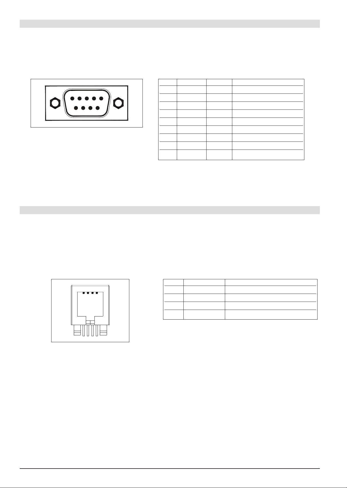
3.6.4 RS-232 port
RS-232 port lets the GF_VEDO TL dialog with RS-232 serial transmission protocol at a baud rate from 9.6 kBaud to
115 kBaud.
The RS-232 port is not optically isolated and uses a 9-pin (male) D-sub connector. Signal assignment is shown in
Table 7.
15
69
Fig. 17
GF_VEDO TL RS-232 port connector
Pin In/Out Code Description
1 I DCD Data Carrier Detect
2 I RxD Data reception
3 O TxD Data transmission
4 O DTR Data Terminal Ready
5 - GND GND
6 I DSR Data Set Ready
7 O RTS Request To Send
8 I CTS Clear To Send
9 I RI Ring Indicator
Table 7
Signal assignment for GF_VEDO TL RS-232 port
3.6.5 RS-485 port
GF_VEDO TL uses the RS-485 port to dialog according to OSI specifications at the physical level defined by standard EIA-485.
The RS-485 port is optically isolated and allows dialog from 9.6 kBaud to 115 kBaud via an RJ10 4p4c connector
(Registered Jack type 10 with 4 positions and 4 contacts).
Signal assignment is shown in Table 8.
1
4
Fig. 18
RJ10 connector for GF_VEDO TL RS-485 port
Pin Name Description
1 GND 2 Tx/Rx + Data reception/transmission (A+)
3 Tx/Rx - Data reception/transmission (B-)
4 +V (reserved) -
Table 8
Signal assignment for GF_VEDO TL RS-485 port
Page 17

17
80543B_MHW_GF_VEDO-TL_0109_ENG
3.6.6 CAN port
The optional CAN port lets GF_VEDO TL dialog via the serial standard (ISO 11898-1 of 2003) for the CAN (Controller Area Network) field bus, also known as CAN-bus.
This protocol is specifically designed for excellent operation even in environments with strong electromagnetic
noise, and can use a balanced potential line such as an RS-485 as means of transmission.
In particular, GF_VEDO TL implements the CANOpen Layer 2 standard. The CAN port is optically isolated and
uses a 9-pin (male) D-sub connector.
Signal assignment is shown in Table 9.
Fig. 19
GF_VEDO TL CAN port connector
Pin In/Out Code Description
1- -2 O CAN_L CAN Low
3 O CAN_GND CAN Ground
4- -5 - EARTH Ground
6- -7 O CAN_H CAN High
8- -9- --
Table 9
Signal assignment for GF_VEDO TL CAN port
3.6.7 USB ports
GF_VEDO TL uses USB ports to dialog via USB (Universal Serial Bus) serial communication standard.
GF_VEDO TL terminals support version USB 1.1 (transmission up to 1.5 Mbit/s).
The USB port connector is type USB-A (4 pins). Signal assignment is shown in Table 10.
Voltage for VBUS is approximately +5V with maximum current of 500mA.
Signals D+ and D- refer to the two (pseudo) differential data communication lines.
14
14
Fig. 20
GF_VEDO TL USB port connector
Pin Description
1 VBUS
2D3D+
4 GND
Shell SHIELD
Table 10
Signal assignment for GF_VEDO TL USB port
The communication cable to be used depends on the type of device to be connected.
3.6.8 AUX port
The AUX port is reserved for future developments.
15
69
Page 18

18
80543B_MHW_GF_VEDO-TL_0109_ENG
3.6.10 Mouse and Keyboard PS2 port
The PS2 port connects the GF_VEDO TL to keyboards and mice conforming to PS2 standard.
Two mini-DIN 6-pin female connectors are used (green: Mouse, violet: Keyboard).
Signal assignment is shown in Tables 12 and Table 13.
Fig. 22 - GF_VEDO TL PS2 port connector for Mouse and Keyboard
Pin In/Out Description
1 KBD Data Data Keyboard
2 N.C. Not connected
3 GND GND
4 5 VDC +5V
5 KBD CLK Keyboard Clock
6 N.C. Not connected
Table 12
Signal assignment for GF_VEDO TL
PS2 Keyboard port
Pin In/Out Description
1 MS Data Data Mouse
2 N.C. Not connected
3 GND GND
4 5 VDC +5V
5 KBD CLK Mouse Clock
6 N.C. Not connected
Fig. 21
GF_VEDO TL KEY & LED port connector
Pin Name Description
1 KEYCLK Keyboard clock
2 KEYOUT Keyboard output
3 KEYIN Keyboard input
4 IRST Reset GT-Tast
5 POWER +5V power supply
6 GND 0V power supply
7 GND 0V power supply
8 +12V +12V power supply
Table 11
Signal assignment for GF_VEDO TL KEY & LED port
1
8
3.6.9 Matrix Keyboard port (KEY & LED)
GF_VEDO TL uses the KEY & LED port to communicate with series TF keyboards.
It uses a high-speed full-duplex synchronous serial interface (SPI) with proprietary communication protocol.
This allows scanning of the key matrix and control of off/on status of LEDs on the keyboard.
The connector is an 8-pin RJ45 without LED, which allows keyboard communication and power.
Signal assignment is shown in Table 11.
Cable length can be a maximum of 1 meter.
Table 13
Signal assignment for GF_VEDO TL
PS2 Mouse port
6 5
34
21
PC-KEY
AUX
PC-KEY
MOUSE
6
6
4
4
2
2
5
5
1
1
3
3
Page 19

19
80543B_MHW_GF_VEDO-TL_0109_ENG
3.7 Access to internal system resources
Before opening the system, ALWAYS switch off the GF_VEDO TL by disconnecting it from the outside power
supply. APhillips screwdriver is needed to access the internal system resources.
Fig. 23 - DOM mass memory in GF_VEDO TL
3.7.1 DOM mass memory
GF_VEDO TL has a mass memory containing the operating system, the application, and user information.
The GF_VEDO board has a 44-pin 2 mm pitch connector that can be used to connect the board to a solid state disk
with IDE AT-compatible interface such as Disk On Module (DOM).
3.7.2 System memory: SODIMM
GF_VEDO TL has a SODIMM (Small Outline Dual In-line Memory Module) system memory, which is more compact
than normal DIMM.
Fig. 24 - SODIMM system memory in GF_VEDO TL
Page 20

20
80543B_MHW_GF_VEDO-TL_0109_ENG
Fig. 25 - Replacing the battery in the GF_VEDO TL
Replace only with the same model battery or with an equivalent compatible with the same operating temperature.
3.7.3 Internal battery
GF_VEDO TL panels use an internal lithium battery (not rechargeable, replaceable).
This makes it possible to keep the data in the static RAM memory when the GF_VEDO TL is off (for a maximum
period of 3 years).
When necessary, replace the battery as follows:
• get a replacement battery (button-type, 24 mm diameter, 3V lithium (CR2430))
• switch off the system by disconnecting it from the outside power supply.
• remove the battery
• dispose of the old lithium battery in compliance with regulations
• insert the new battery as shown in Figure 25
• switch on the system.
Note:
if the battery is replaced quickly(in less than 15 minutes) there is no loss of data maintained by the backup battery.
Page 21

21
80543B_MHW_GF_VEDO-TL_0109_ENG
Modbus TCP/IP
4 • CONNECTION EXAMPLES
[HMI]
GF_VEDO TL 104CT
[I/O]
Gilogik
Modbus RTU
[PID]
GFX4
Company Ethernet
[HMI]
GF_VEDO TL 104CT
[DRIVE]
XVy
[I/O]
Gilogik
CANopen
Page 22

22
80543B_MHW_GF_VEDO-TL_0109_ENG
Model GF_VEDO TL GF_VEDO TL GF_VEDO TL GF_VEDO TL
65CT 65CK 104CT 104CK
Display
Type TFT colors
No. colours 262k
Size 6.5” 10.4”
Display area 132.5x99.4 mm 211.2x158.4 mm
Resolution VGA 640x480 SVGA 800x600
Luminosity 500 cd/m
2
230 cd/m
2
Contrast 450:1 500:1
Backlighting CCFL
Visual angle O/V 140°/120° 120°/100°
Keyboard
Keys - 47 - 54
Touch Screen
Type 4 wires resistance - 4 wires resistance Life >1M operations - >1M operations Controller integrated - integrated -
Processor
Type GEODE SC1200
Frequency 266MHz
Core x86
Memory
System memory (DRAM) 128MB - 256MB
User memory (SRAM) 2MB
Mass memory (DOM) 64MB - 1GB
I/O Pheripherals
AUTOSTART (optional) Connector: 3-pin female, screw type
Ethernet ETH1 - ETH2 2 x Ethernet 10/100 Mbps (RJ45 with LED)
RS-232 (optional) 1 x RS232: not optoisolated from 9.6 to 115kBaud (D-Sub 9 PM)
RS-485 1 x RS485: optoisolated from 9.6 to 115kBaud (RJ10)
CAN (optional) 1 x CANopen: from 9.6 to 115kBaud (D-Sub 9 PM)
USB 2 x USB 1.1 Host (500mA) (connector: 4-pin type A)
KEY & LED - RJ45 connector - RJ45 connector
without LED without LED
Keyboard/Mouse PS2 Connector: 6-pin miniDIN (green: Mouse - violet: Keyboard)
Operative Systems
VxWorks or WindowsXP Embedded
Various
Power supply 24VDC ±25% (connector: 3-pin female, screw type)
Max consumption at 24VDC 600mA 600mA 700mA 700mA
Resettable fuse Current surge protection at input circuit
Battery 3V, 270mA/h lithium, replaceable, unrechargeable, accessible from inside
Model: botton CR2430
Maximum granted storage of data in Static RAM: 3 years (terminal off)
RTC hardware clock Clock/calendar with buffer battery
Faceplate protection IP65 (IEC 529)
Certifications CE, UL
Dimensions
Faceplate (mm) 187 x 133 187 x 230 266 x 192.5 266 x 289
Drilling (mm) 179.5 x 127 180 x 222 258 x 184 258 x 281
Max panel thickness (mm) 4444
Weight (Kg) 0.9 1.3 1.4 1.9
Operating/Storage condition
Operating temperature 0 ... +50°C (IEC 68-2-14)
Storage temperature -20° ... +70°C (IEC 68-2-14)
Operating and storage humidity 5 ... 95% RH non-condensing (IEC 68-2-3)
5 • SUMMARY OF CHARACTERISTICS
Table 14 - Summary of GF_VEDO TL characteristics
Page 23

23
80543B_MHW_GF_VEDO-TL_0109_ENG
6 • TECHNICAL/COMMERCIAL INFORMATION
This section contains information regarding the Controller order codes and the main accessories available.
As stated in the Preliminary Warnings of these Instructions for Use, correct interpretation of the Controller order
code allows the hardware configuration for the controller to be identified immediately and so it is essential to quote
the order code each time the Gefran Customer Care Service is contacted for assistance with any problems.
Order code
(1) (2)
Kindly contact GEFRAN for information on available codes.
MODEL
65CT
GF_VEDO
GF_VEDO TL 65CT
65CK
GF_VEDO TL 65CK
104CT
GF_VEDO TL 104CT
104CK
GF_VEDO TL 104CK
OPERATING SYSTEM
VW0
VxWorks
DOM: 64MB
RAM: 128MB
XE0
WinXP Embedded
DOM: 1GB
RAM: 256MB
EXPANSION 1
00
None
C1
CANopen
D1
DeviceNet
EXPANSION 2
00
None
S1
RS232 + Autostart
LEXAN
G
Gefran
N
Neutral
(1)
(2)
In conformity to 2004/108/CE (EMC) and 2006/95/CE (LVD) with reference to standards: CEI-EN 61131-2 (product) - EN 61010-1
(safety).
Conformity UL508 Certif. 20080331 File no. E198546
 Loading...