

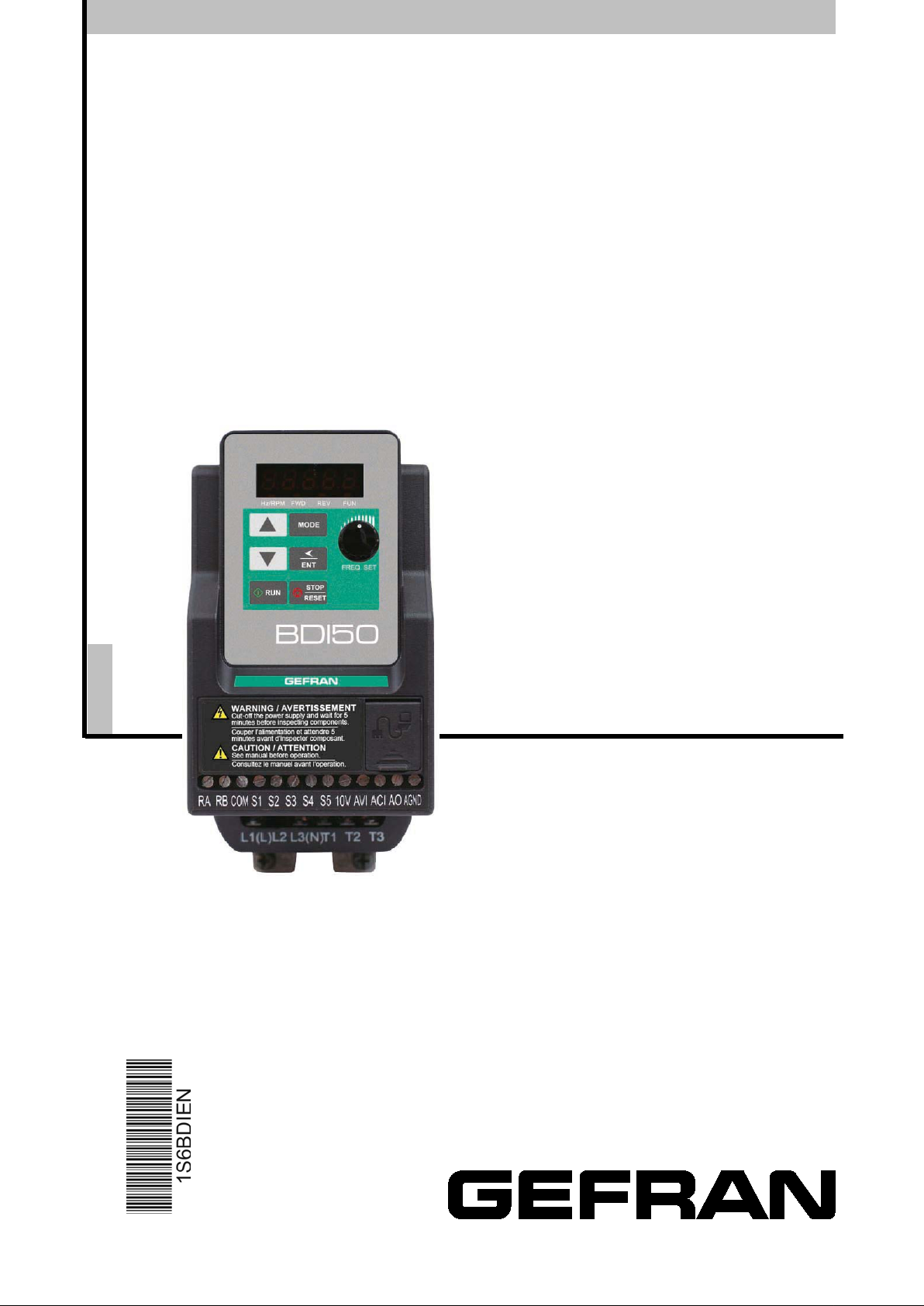
gefran BDI50-1004-KXX-2M-N, BDI50-1007-KXX-2M-P-F, BDI50-2015-KXX-2M-N, BDI50-1007-KXX-2M-N, BDI50-1004-KXX-2M-P-F User Manual
...Page 1
COMPACT V/f & SENSORLESS
INVERTER
BDI50
English
User manual
Rev. 0.7 – 7-11-2017
Page 2

------------------------------------------------------------------------------------------------------------------------------
Software version
This manual is updated according the software version V 1.06
The identification number of the software version is indicated on the identification plate of the drive or can be checked
with the par. 13.01.
Thank you for choosing this Gefran product.
We will be glad to receive any possible information which could help us improving this manual. The e-mail address is
the following: techdoc@ gefran.com.
Before using the product, read the safety instruction section carefully.
Keep the manual in a safe place and available to engineering and installation personnel during the product functioning
period.
Gefran S.p.A has the right to modify products, data and dimensions without notice.
The data can only be used for the product description and they can not be understood as legally stated properties.
All rights reserved
Page 3

Table of Contents
Chapter 0
Preface
0-1
0.1 Preface
0-1
Chapter 1
Safety Precautions
1-1
1.1 Before Power UP
1-1
1.2 During Power UP
1-2
1.3 Before Operation
1-2
1.4 During Operation
1-3
1.5 Inverter Disposal
1-3
Chapter 2
Part Number Definition
2-1
2.1 Model part number
2-1
2.2 Standard Product Specification
2-2
Chapter 3
Environment & Installation
3-1
3.1 Environment
3-1
3.2 Installation
3-3
3.2.1 Installatio n me thods
3-3
3.2.2 Installation space
3-6
3.2.3 Derating curves
3-9
3.2.4 Capacitor reforming Guide after long storage
3-10
3.3 Wiring guidelines
3-11
3.3.1 Main considerations
3-11
3.3.2 Power cables
3-13
3.3.3 Control cable selection and wiring
3-13
3.3.4 Wiring and EMC guidelines
3-14
3.3.5 Failure liability
3-15
3.3.6 Considerations for peripheral equipment
3-17
3.3.7 Ground connection
3-18
3.4 Specifications
3-19
3.4.1 Product Specifications
3-19
3.4.2 General Specifications
3-21
3.5 Standard wiring
3-23
3.5.1 200V Single phase (NPN inpu t)
3-23
3.5.2 200V Single phase (PNP input)
3-24
3.5.3 230V Three ph as e (NPN input)
3-25
3.5.4 400V Three phase (PNP input)
3-26
3.5.5 400V Three phas e (NPN input)
3-27
3.6 Terminal Description
3-29
3.6.1 Description of main circuit terminals
3-29
3.6.2 Control circuit terminal description
3-30
3.7 Dimensions and weight
3-32
3.8 EMC filter Disconnection
3-37
I
Page 4

Chapter 4
Software Index
4-1
4.1 Keypad Description
4-1
4.1.1 Operator Panel Functions
4-1
4.1.2 Digital Display Description
4-2
4.1.3 Digital Display Setup
4-4
4.1.4 Example of Keypad Operation
4-6
4.1.5 Operation Control
4-8
4.2 Programmable Parameter Groups
4-9
4.3 Parameter Function Description
4-24
Chapter 5
Troubleshooting and Maintenance
5-1
5.1 Error Display and Corrective Action
5-1
5.1.1 Manual Reset and Aut o-Reset
5-1
5.1.2 Keypad Operation Error Instruction
5-3
5.1.3 Special conditions
5-4
5.2 General troubleshooting
5-5
5.3 Routine and periodic inspection
5-6
5.4 Maintenance
5-7
Chapter 6
Accessories
6-1
6.1 Input choke Specific ati ons
6-1
6.2 Output choke Specifications
6-1
6.3 Fuse Specification
6-1
6.4 Fuse Specification (UL Model Recommended)
6-2
6.5 Braking Resistor
6-3
6.6 Copy Unit (KB-BDI/VDI)
6-4
6.7 Communication options
6-4
6.8 RJ45 to USB connecting Cable (1.8m)
6-5
Appendix 1
BDI50 Parameters Setting List
App1-1
Appendix 2
Instructions for UL
Appendix 3
BDI50 Communication protocols
A3.1 Modbus communi cati on pr otocol
A3.2 BACnet communic ati on pr otocol
Appendix 4
Cable RJ45 to USB instruction manual
Appendix 5
BDI50 series accessories manual
Appendix 6
Consignes de sécurité
App2-1
App3-1
App3-1
App3-18
App4-1
App5-1
App6-1
II
Page 5
※
Indicates a potential hazard that could cause death or serious
personal injury if misused.
Indicates that the inverter or the mechanical system might be damaged
if misused.
Ensure that the Inveter Ground terminal is connected correctly.
CMOS ICs on the inverter’s main board are susceptible to static electricity. Do
Chapter 0 Preface
0.1 Preface
To extend the performance of the product and ensure personnel safety, please read
this manual thoroughly before using the inverter. Should there be any problem in
using the product that cannot be solved with the information provided in the manual,
contact our technical or sales representative who will be willing to help you.
Precautions
The inverter is an electrical product. For your safety, there are symbols such as
“Danger”, “Caution” in this manual as a reminder to pay attention to safety
instructions on handling, installing, operating, and checking the inverter. Be sure to
follow the instructions for highest safety.
Danger
Caution
Danger
Risk of electric shock. The DC link capacitors remain charged for five
minutes after power has been removed. It is not permissible to open the
equipment until 5 minutes after the power has been removed.
Do not make any connections when the inverter is powered on. Do not check
parts and signals on circuit boards during the inverter operation.
Do not disassemble the inverter or modify any internal wires, circuits, or
parts.
Caution
Do not perform a voltage test on parts inside the inverter. High voltage can
destroy the semiconductor components.
Do not connect T1, T2, and T3 terminals of the inverter to any AC input
power supply.
not touch the main circuit board.
0-1
Page 6

Chapter 1 Safety Precautions
Make sure the main circuit connections are correct. Single phase L1( L) ,L3( N ) , and
not be mistaken for T1,T2 and T3. Oth er wise, inverter damage can result .
The line voltage applied must comply with the inverter’s specified input
To avoid the front cover from disengaging, or other damge do not carry the inverter
damage to the keypad or the inverter.
This product is sold subject to EN 61800-3 and EN 61800-5-1.
Work on the device/system by unqualified personnel or failure to comply with
Only permanently-wired input power connections are allowed.
1.1 Before Power Up
Danger
Three phase L1(L),L2,L3(N); 400V : L1,L2,L3 are power-input terminals and must
Caution
voltage.(See the nameplate)
by its covers. Support the drive by the heat sink when transporting. Improper
handling can damage the inverter or injure personnel and should be avoided.
To avoid the risk of fire, do not install the inverter on a flammable object.Install on
nonflammable objects such as metal.
If several inverters are placed in the same control panel, provide heat removal
means to maintain the temperature below 50 degree C to avoid over heat or fire.
When disconnecting the remote keypad, turn the power off first to avoid any
Warning
In a domestic environment this pr oduct may cause radio interference in which
case the user may be required to apply corrective measures.
Motor over temperature protection is not provided.
Caution
warnings can result in severe personal injury or serious damage to material. Only
suitably qualified personnel trained in the setup, installation, commissioning and
operation of the product should carry out work on the device/system.
1-1
Page 7
1.2 During Power Up
When the momentary power loss is longer than 2 seconds, the inverter will not
for 2 seconds.
Danger
have sufficient stored power for its control circuit. Therefore, when the power is
re-applied, the run operation of the inverter will be based on the setup of
following parameters:
• Run parameters. 00-02 or 00-03.
• Direct run on power up. Parameter. 07-04 and the status of external run
switch,
Note-: the start operation will be regardless of the settings for parameters
07-00/07-01/07-02.
Danger. Direct run on power up.
If direct run on power up is enabled and inverter is set to external run
with the run FWD/REV switch closed then the inverter will restart.
Danger
Prior to use, ensure that all risks and safety implications are considered.
When the momentary power loss ride through is selected and the power loss is
short, the inverter will have sufficient stored power for its control circuits to
function, therefore,when the power is resumed the inverter will automatically
restart depending on the setup of parameters 07-00 & 07-01.
1.3 Before Operation
Caution
Make sure the model and inverter capacity are the same as that set in
parameter 13-00.
Note : On power up the supply voltage set in parameter 01-01 will flash on display
1-2
Page 8
1.4 During Operation
Caution
Do not touch heat radiating components such as heat sinks and brake resistors.
The inverter can drive the motor from low speed to high speed. Verify the allowable
minutes after the power has been removed.
Caution
Make sure that the power is switched off before disassembling or checking
harmful gases if burnt.
To avoid electric shock, do not take the front cover off while power is on.
restart function is enabled.
peration of the stop switch is different than that of the emergency stop switch.
de-activated to become ef fect ive.
Danger
Do not connect or disconnect the motor during operation. Otherwise, It may
cause the inverter to trip or damage the unit.
Danger
The motor will restart automatically after stop when auto-
In this case, care must be taken while working around the drive and associated
equipment .
The o
The stop switch has to be activated to be effective. Emergency stop has to be
speed ranges of the motor and the associated machinery.
Note the settings related to the braking unit.
Risk of electric shock. The DC link capacitors remain charged for five minutes after
power has been removed. It is not permissible to open the equipment until 5
The Inverter should be used in environments with temperature range from
-10… +40°C / 14…104℉ (size 1) or -10…+50°C / 14…122℉ (all other
sizes) and relative humidity of 95%.
Danger
any components.
1.5 Inverter Disposal
Caution
Please dispose of this unit with care as an industrial waste and according to your
required local regulations.
The capacitors of inverter main circuit and printed circuit board are considered as
hazardous waste and must not be bur nt.
The Plastic enclosure and parts of the inverter such as the cover board will release
1-3
Page 9

Chapter 2 Part Number Definition
BDI50
EMC Filter:
kW
Mechanical drive sizes
2.1 Model part number
-X XXX -K X X -X -Y -Y
PNP / NPN:
Rated voltage:
F = included; [Empty] = not included
N = NPN input;
P = PNP input;
NP = PNP and NPN
2M = 230 Vac, 1ph;
2T = 230 Vac, 3ph;
4 = 400 Vac, 3ph
Software:
Braking unit:
Keypad:
Drive power, in
BDI50 drive series
X = standard
B = included;
X = not included
K = Integrated (LED keypad with 5-digits
7-segment display)
2-1
Page 10
2.2 Standard Product Specification
Model
BDI50-1004-KXX-2M-N
BDI50-1007-KXX-2M-N
BDI50-2015-KXX-2M-N
BDI50-2022-KXX-2M-N
BDI50-1004-KXX-2M-P-F
BDI50-1007-KXX-2M-P-F
BDI50-2015-KXX-2M-P-F
BDI50-2022-KXX-2M-P-F
BDI50-1007-KXX-2T-N
BDI50-2015-KXX-2T-N
BDI50-2022-KXX-2T-N
BDI50-3037-KBX-2T-NP
BDI50-4055-KBX-2T-NP
BDI50-4075-KBX-2T-NP
BDI50-2007-KBX-4-N
BDI50-2015-KBX-4-N
BDI50-2022-KBX-4-N
BDI50-3037-KBX-4-NP
BDI50-3055-KBX-4-NP
BDI50-4075-KBX-4-NP
BDI50-4110-KBX-4-NP
BDI50-2007-KBX-4-P-F
BDI50-2015-KBX-4-P-F
BDI50-2022-KBX-4-P-F
BDI50-3037-KBX-4-NP-F
BDI50-3055-KBX-4-NP-F
BDI50-4075-KBX-4-NP-F
BDI50-4110-KBX-4-NP-F
Supply
Voltage
(Vac)
1ph,
200~240V
+10%/-15%
3ph,
200~240V
+10%/-15%
3ph,
380~480V
+10%/-15%
Frequency
(Hz)
50/60Hz
50/60Hz
50/60Hz
(HP)
(kW)
0.5 0.4
1 0.75
2 1.5
3 2.2
0.5 0.4
1 0.75
2 1.5
3 2.2
1 0.75
2 1.5
3 2.2
5 3.7
8 5.5
10 7.5
1 0.75
2 1.5
3 2.2
5 3.7
8 5.5
10 7.5
15 11
1 0.75
2 1.5
3 2.2
5 3.7
8 5.5
10 7.5
15 11
Model EMC Filter
NPN PNP Built-in None
◎
◎ ◎
◎
◎ ◎
◎
◎ ◎
◎
◎ ◎ ◎ ◎
◎ ◎
◎ ◎ ◎ ◎
◎
◎ ◎ ◎
◎
◎
◎ ◎
◎
◎ ◎
◎ ◎ ◎
◎
◎ ◎ ◎
◎
◎ ◎
◎ ◎
◎ ◎
◎ ◎
◎ ◎
◎ ◎
◎
◎
◎
◎
◎ ◎
◎ ◎
◎ ◎
◎
◎
Braking
Built-in
◎
◎
◎
◎
◎ ◎
◎ ◎
◎ ◎
◎ ◎
◎ ◎
Unit
◎
◎
◎
◎
◎
◎
◎
Short circuit capacity is below 5000A/240V or 5000A/480V.
The voltage for 200~240V models is 240V, 380~480V models is 480V.
2-2
Page 11

3-1
Chapter 3 Environment & Installation
Protection
Protection
class
Suitable environment
Storage
temperature
Relative
Humidity
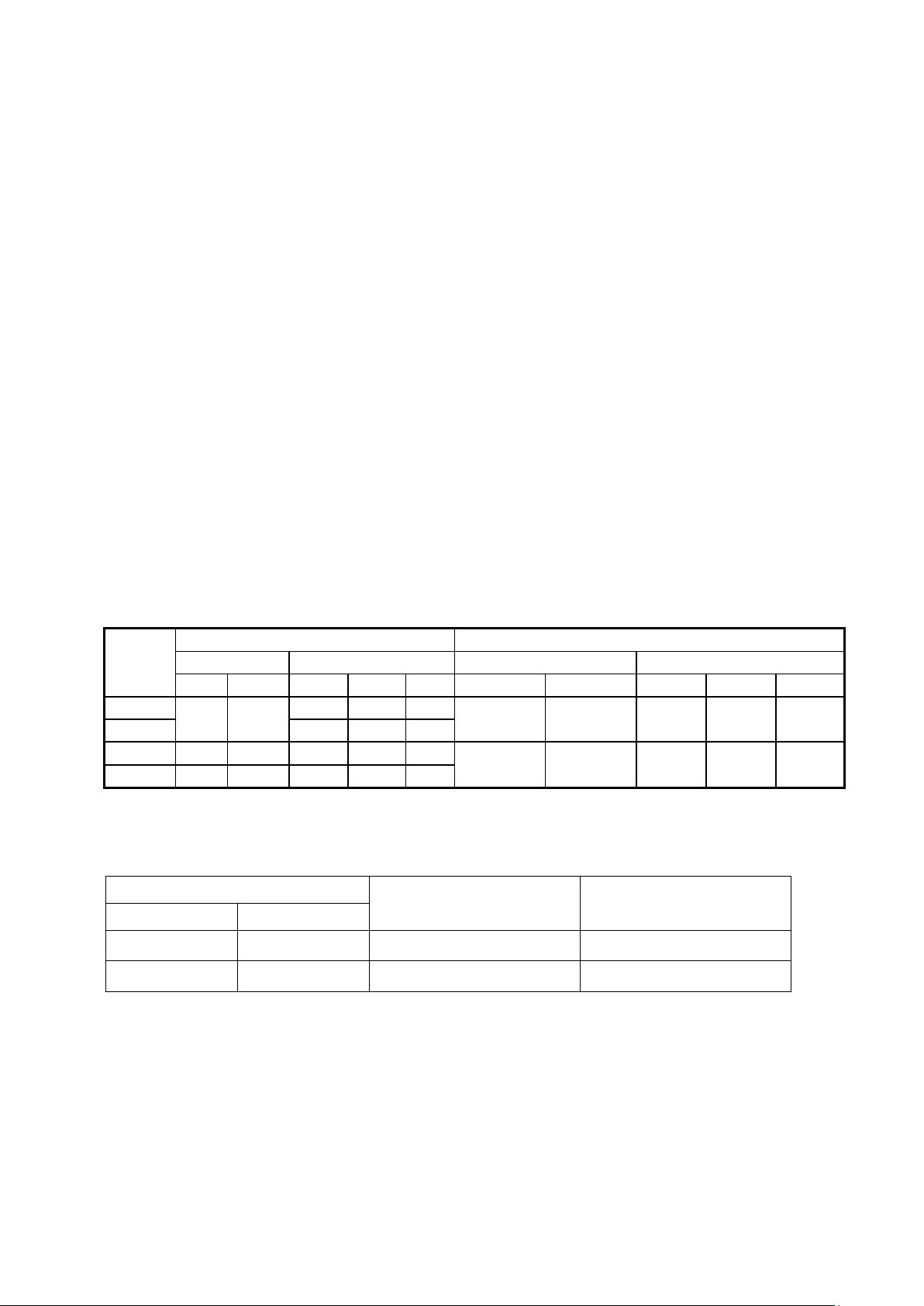
Altitude:Below 1000m (3281ft)
See ch. 3.2.3 Derati ng c ur v es .
2G (19.6m/s²) for 57~150Hz and below.
0.3mm for 10~57Hz (According to IEC60068-2-6 standard)
Direct sunlight, Rain or moisture
Oil mist and salt
Dust, lint fibres, small metal filings and corrosive liquid and gas
Electromagnetic int erference from sources such as welding equipment
Radioactive and flamm able mat er i al s
Excessive vibration from machines such as stamping, punching machines
Add vibration-proof pads if necessary
3.1 Environment
Installation environment has a direct effect on the correct operation and the life expectancy of the
inverter, Install the inverter in an environment complying with the following conditions:
IP20
-10~40°C (size 1) -10~50°C (other sizes)
Operating
temperature
If several inverters are installed in the same control panel, ensure
adequate spacing and provide the necessary cooling and ventilation for
successful operation .
-20~60°C
Max 95% (without condensation)
Altitude
Shock
It is required to reduce 2% of inverter rated current at each additional
100m. The maximum altitude is 300 0 m
Installation site
Install in an environment that will not have an adverse effect on the operation of the unit
and ensure that there is no exposure to areas such as that listed below:
Page 12
3-2
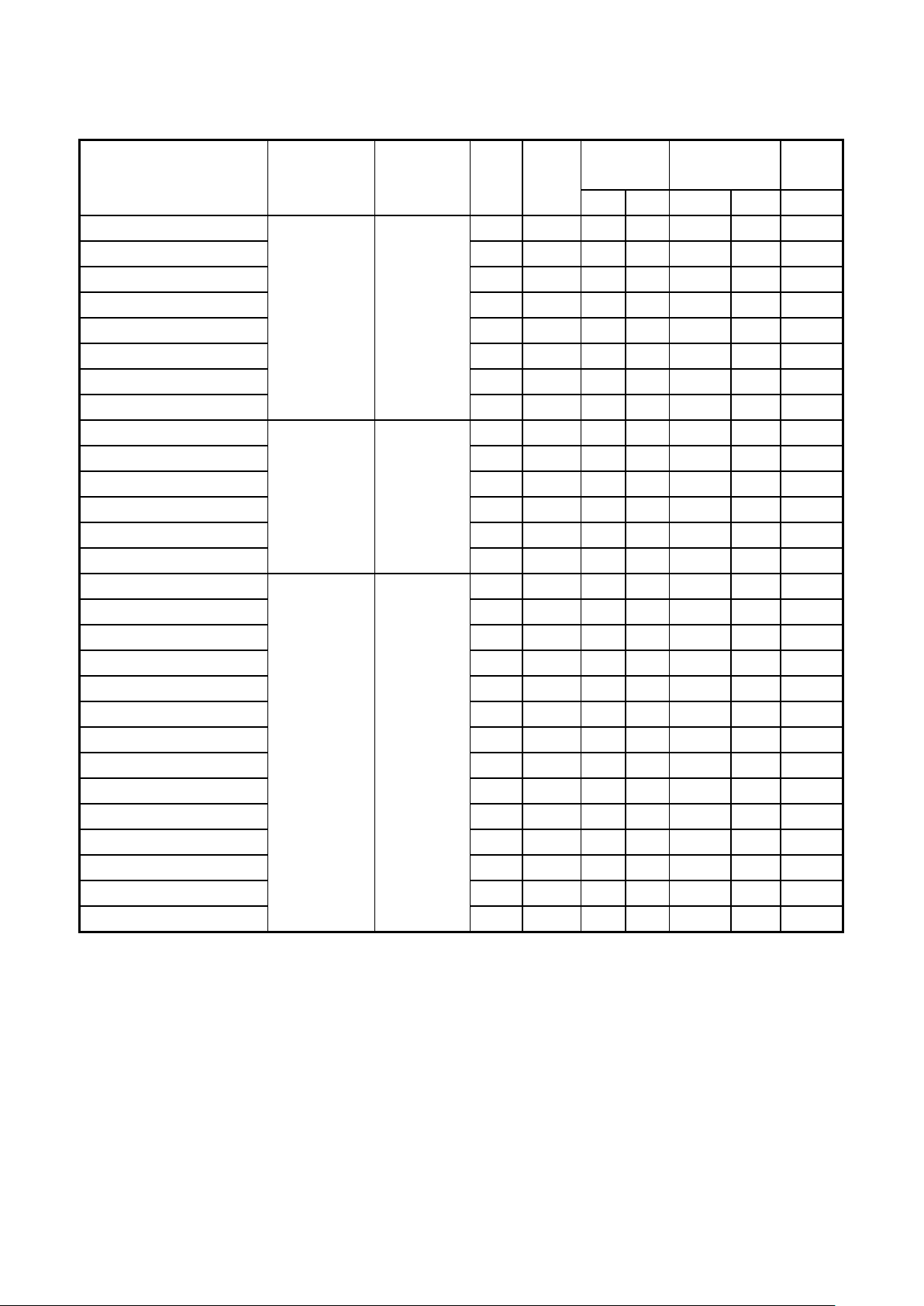
Product Overview
Size 3
Size 4
RS485
Operator
TM2
terminal
TM1
terminal
Ground
terminal
Operator
RS485
TM2
terminal
TM1
terminal
Ground
terminal
Size 1
Size 2
Panel
port
Panel
port
Page 13
3-3
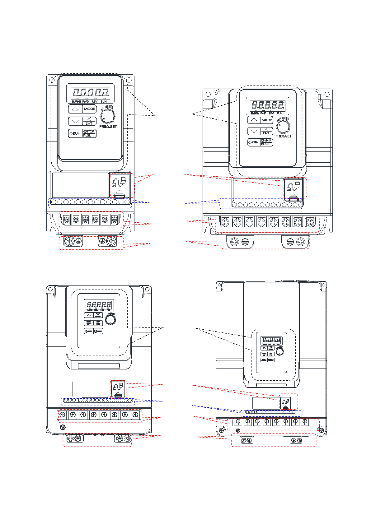
3.2 Installation
M4
1. Metal plate adaptor
2. Plastic adaptor
Snap hooks
1. Metal plate adaptor
2. Plastic adaptor
Snap hooks
3. screws
3. screws
Assembly:
Disassembly:
3.2.1 Installation methods
Size1. Mounting on a flat surface.
Din rail type installation:
Din rail kit includes a plastic and a metal adaptor plates.
Assembly Steps:
1) Attach the metal adaptor plate to the inverter base with the screws provided.
2) Attach the plastic Din rail adaptor to the metal adaptor plate.
3) Push the plastic adaptor forward to lock into position.
Disassembly Steps:
1) Unlock by pushing the snap hooks
2) Retract and remove the plastic Din rail adaptor.
3) Unscrew the metal plate &Remove
Note:
KIT DIN BDI50 Size 1 (Din rail kit part model), including the following parts
1. Metal plate adaptor
2. Plastic adaptor
3. Chamfer head screw: M3×6
Page 14
3-4
M4
Mounting
Dismounting
Assembly:
Disassembly:
Plastic Adaptor plate
Snap hook
Middle Snap hook
Snap hook
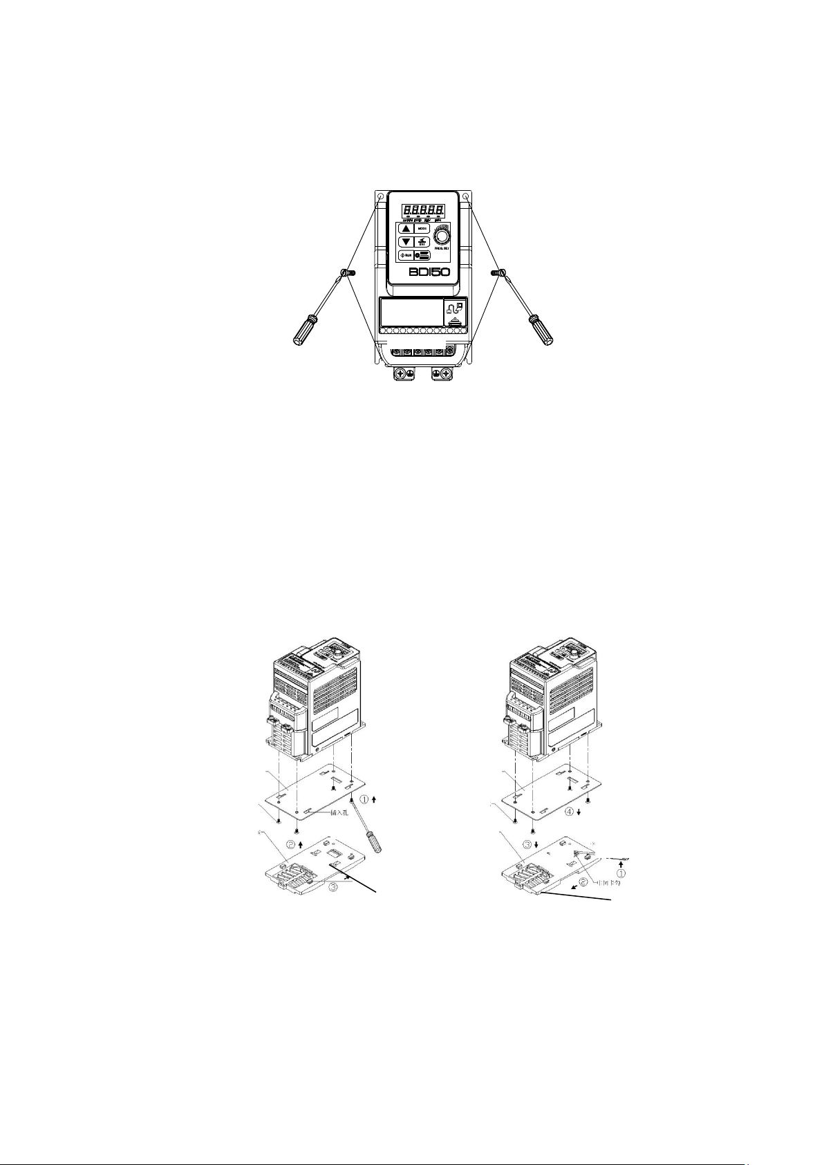
Size 2: Mounting on a flat surface.
Din rail type installation:
Din rail kit includes a plastic adaptor plate as an attachment for the inverter base.
Refer to Diagram below:
Din Rail Mounting & Dismounting as shown in the diagram below:Use a 35mm Din Rail.
Plastic adaptor plate.
KIT DIN BDI50 Size 2 (Size 2 Din rail kit model)
Page 15

3-5
Size 3. Mounting on a flat surface
M4
螺丝
M4
螺丝
M4 screw
M4 screw
Size 4. Mounting on a flat surface
Page 16
3-6
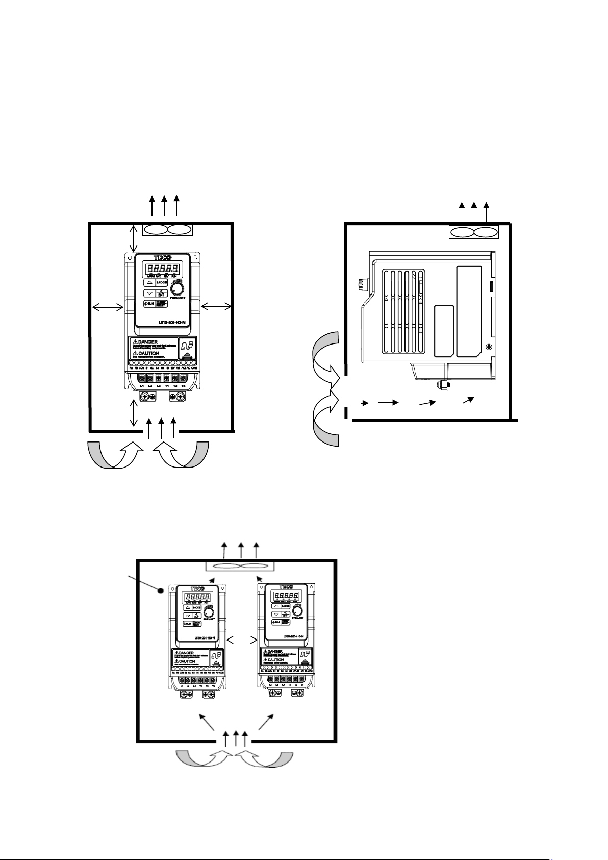
3.2.2 Installation space
5cm
5cm
12cm
12cm
Front view
Fan
Fan
Side view
Provide the necessary
CONTROL
PANEL
5cm
Provide sufficient air circulation space for cooling as shown in examples below.
Install the Inverter on surfaces that provide good heat dissipation.
Single unit Installation
Install the inverter verticality to obtain effective cooling.
Multiple Installation
physical space and cooling
based on the ambient
temperature and the heat
loss in the panel
Page 17
3-7
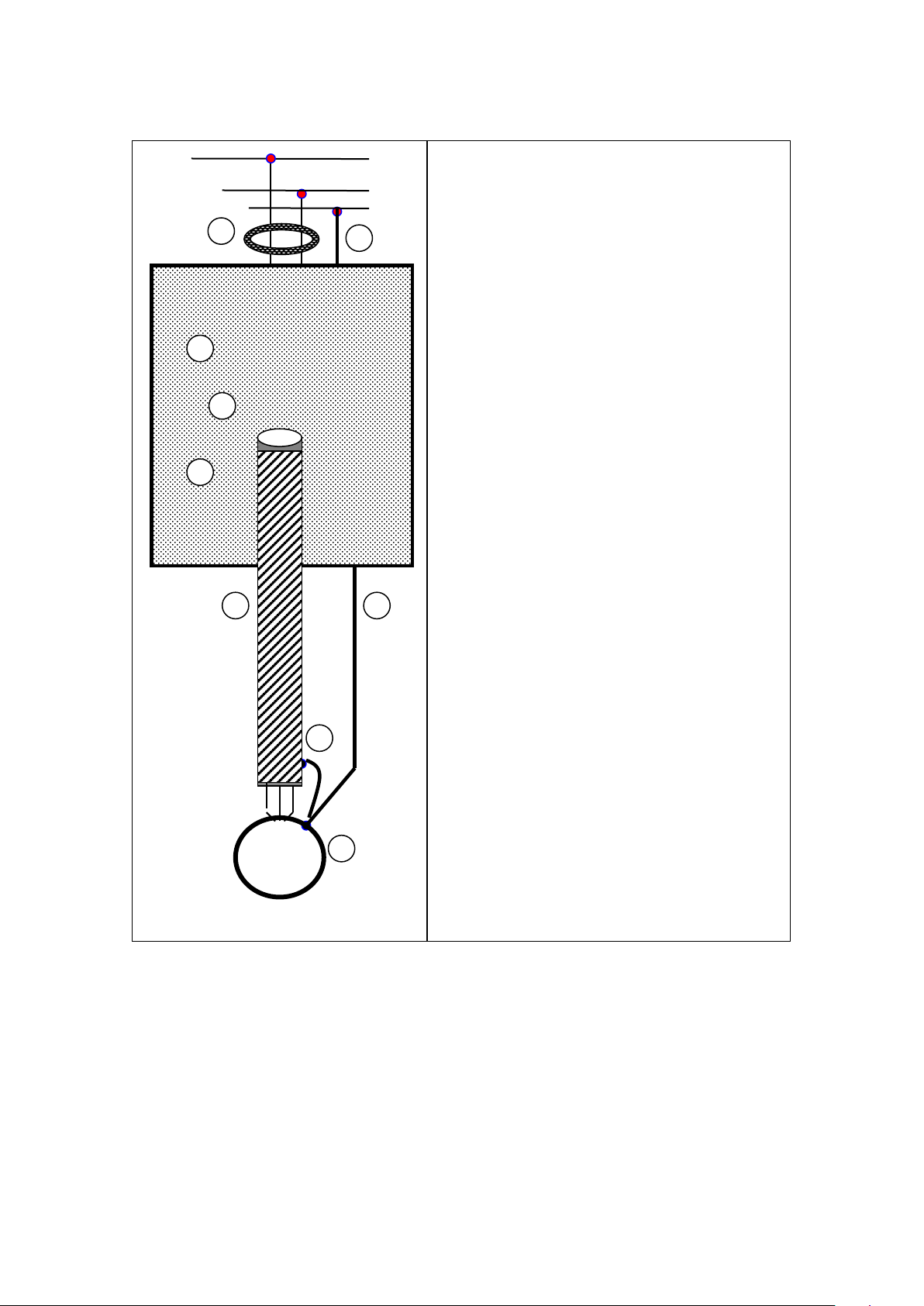
Installation for Grounding kit
Grounding kit:
As bellowed diagram, use screw to install EMC metal plate into heatsink.
Size 1 Size 2
Page 18
3-8
Grounding kit option insta llation diagram and instruction (Example)
1
2
6
4
3
5
5
1
2
6
3
4
5
5
Size 1 Size 2
1. Grounding kit to be mounted on the drive (earth casing), please follow the diagram to
install.
2. Unshielded power supply lines or cable.
3. Unshielded wires or cable for the output of the relay contacts.
4. Stainless steel cable clamps.
Attach and earth the shielding of cables 5 and 6 as close as possible to the drive:
Strip the cable to expose the shielding;
Attach the cable to the plate 1, attaching the clamp on the stripped part of the
shielding.
The shielding must clamped tightly enough to metal sheet to ensure g ood con tact.
5. Shielded power supply cable for connecting motor which connect to earth at both
ends. The shielding must be continuous, and if intermediate terminals are used, they
must be placed in EMC shielded metal boxes.
6. Shielded cable for control-signal wiring.
For applications requiring several conductors, use cables with small cross-section
(0.5 mm2, 20 AWG).
For cables 5 and 6, the shielding must be connected to earth at both ends. The
shielding must be continuous, and if intermediate terminals are used, they must be
placed in EMC shielded metal boxes.
Notice:
● If using external EMC input filter, it must be mounted under the drive and connected
directly to the line supply via an unshielded cable. Link 3 on the drive is then via the
filter output cable.
● The HF equipotential earth connection between the drive, motor and cable shielding
does not remove the need to connect the PE conductors (green-yellow) to the
appropriate terminals on each device.
Page 19
3-9
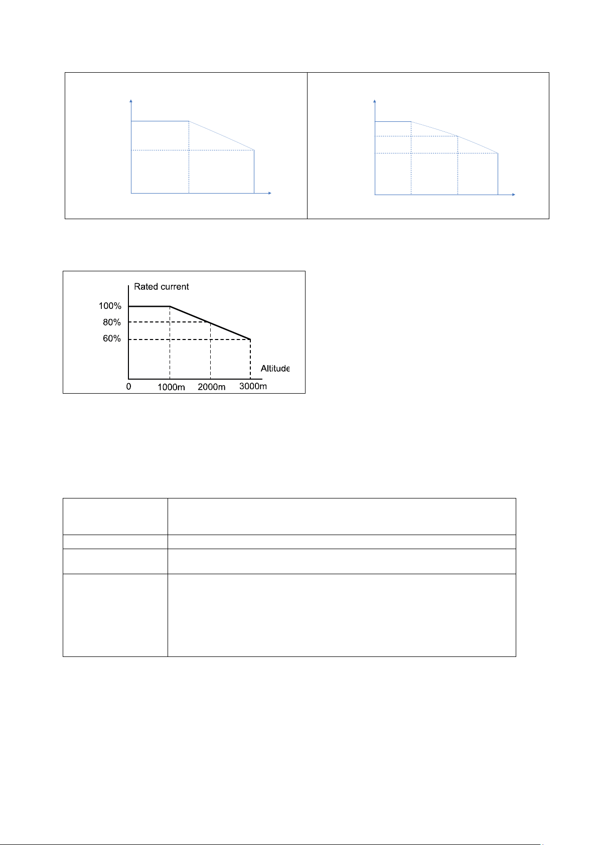
3.2.3 Derating curves
1004-…2M, 1007-…2M/2T (40℃)
2015/2022-…2M/2T (50℃)
100%
80
%
5
16
Rated Current(In)
Carrier Frequency
(kHz)
100%
90%
10
16
Rated Current
(
In)
Carrier Frequency(kHz
)
3037-..2T (50℃) (*)
4055-…2T (50℃)
100%
94%
10 16
Rated Current(In)
Carrier Frequency(kHz)
4075-…2T (50℃)
2007 / 2015 /2022-…4 (50℃)
100%
70%
10 16
Rated Current(In)
Carrier Frequency(kHz)
3037-…4 (50℃)
3055-…4 (50℃)
100
%
87%
10
16
Rated Current(In)
Carrier Frequency(kHz)
100%
84.6%
61.5%
5 10 16
Rated Current(In)
Carrier Frequency(kHz)
100%
70%
55%
5 10 16
Rated Current(In)
Carrier Frequency (kHz)
100%
90%
10
16
Rated Current(In)
Carrier Frequency(kHz )
Curves below show the applicable output current derate due to setting of carrier
frequency, the ambient operating temperatures of 40 and 50 degree C and installation
altitude.
(*) BDI50-3037-…-2T do not need to decrease the current rating in 50°C ambient temperature.
Page 20
3-10
4075-…4 (50℃)
4110-…4 (50℃)
100%
60.6%
8
16
Rated Current(In)
Carrier Frequency(kHz)
100
%
70%
55%
5 10 16
Rated Current(In)
Carrier Frequency(kHz)
1year
Apply rated voltage (1) of i nverter in the normal way
Between
1-2 years
Apply rated voltage of inverter to the product for one hour before using
the inverter
Once the procedures com plet ed, inverter just can be used n ormally.
Derating curve for altitude
3.2.4 Capacitor reforming Guide after long storage
For correct performance of this product after long storage before use it is important that
Inverter Capacitors are reformed according to the guide below:
Storage time
Procedure to re-apply voltage
≦
Use a variable AC power supply to
1. Connecting 25% rated voltage of inverter for 30 minutes.
≧2 years
2. Connecting 50% rated voltage of inverter for 30 minut es.
3. Connecting 75% rat ed voltage of inverter for 30 minut es.
4. Connecting 100% rat ed voltage of inverter for 210 minute s.
(1) Please refer the rated voltage according to model label of inverter.
Page 21
3-11
3.3 Wiring Guidelines
TM1
TM2
Cable Size
Tightening torque
Cable Size
Tightening torque
AWG
mm²
kgf.cm
Ibf.in
Nm
AWG
mm²
kgf.cm
Ibf.in
Nm
Size 1
14
12.15
1.37
Size 2
12.24
10.62
1.2
Size 3
18~8
0.82~8.4
18
15.58
1.76
Size 4
14~6
2~13.3
24.48
21.24
2.4
Device Rating
voltage
HP
3.3.1 Main considerations
1 Tightening Torque f or Screw terminals:Refer to the tables 3-1, when using a
screwdriver or any other suitable tools to make connections.
2 Power terminals:
Single phase : L1 (L), L3 (N)
Three-phase 200V models: L1 (L), L2, L3 (N)
400V models: L1, L2, L3
3 For all cabling use copper wires and the cable size shall be according to the table
below rated at 40 degrees Celsius.
4 Power & Control cable Minimum rated voltage
240V AC system, 300V AC.
480V AC system, 600V AC.
5 Control cables should be separated from the power cables. Do not place them in the
same cable tray or cable trunking to prevent against electrical interference.
Table 3-1
Size
22~10 0.34~6
24~12 0.5~2.5 4.08 3.54 0.4
24~12 0.5~2.5 5.1 4.43 0.5
6 The maximum RMS symmetrical Current Ratings and voltage are listed as below:
Short circuit Rating Maximum Voltage
220V 0.2~10 5000A 240V
440V 1~15 5000A 480V
Page 22

3-12
7 Electrical ratings of terminals:
Supply voltage
Specification
0.4 / 0.75
0.5 / 1
220~240V
30
1.5 / 2.2
2 / 3
220~240V
30
0.75 / 1.5 / 2.2
1 / 2 / 3
380~480V
600
28
3.7
5
220~240V
300
45
5.5 / 7.5
7.5 / 10
220~240V
300
65
3.7 / 5.5
5 / 7.5
380~480V
600
45
7.5 / 11
10 / 15
380~480V
600
65
Power (kW) Horsepower
Voltage (Volt) Current(A)
300
Page 23

3-13
3.3.2 Power Cables
Inverter
IM
Power
MCCB
Inverter IM
Machine
Insulation transformer
Power
MCCB
Protective covering
Inverter IM
Machine
RFI
Filter
Power
MCCB
Connect the shield to inverter
Do not connect this end
Supply power cable must be connected to TM1 terminal block, terminals L1(L) and L3(N) for
single phase 200V supply, L1(L), L2, L3(N) for three phase 200V supply and L1, L2, L3 for
three phase 400V supply.
Motor cable must be connected to TM1 terminals. T1, T2, T3.
Warning: Connection of Supply line cable to terminals T1,T2& T3 will result in serious
damage to the drive components.
Example power connections: Inv er ter with dedicat ed power line.
Install a Supply RFI filter or Isolation transformer when the power source is
shared with other high power electrical equipment as shown below.
3.3.3 Control Cable selection and Wiring
Control cables should be connected to terminal block TM2.
Choose power & Control cables according to the following criteria:
Use copper wires with correct diameter and temperature rating of 60/75°C.
Minimum cable voltage rating for 200V type inverters should be 300VAC.
Route all cables away from other high voltage or high current power lines
to reduce interference effects.
Use a twisted pair shielded cable and connect the shield (screen) wire to the ground
terminal at the inverter end only. Cable length should not exceed 50 meters.
Shielding sheath
ground terminal
Page 24

3-14
3.3.4 Wiring and EMC guidelines
For effective interference suppression, do not route power and control cables in the same
conduit or trunking.
To prevent radiated noise, motor cable should be put in a metal conduit. Alternatively an
armored or shielded type motor cable should be used.
For effective suppression of noise emissions the cable armor or shield must be grounded at
both ends to the motor and the in verter ground. These connections should be as short as
possible.
Motor cable and signal lines of other control equipment should be at the least 30 cm apart.
BDI50-…-F series with built-in EMC filter
All BDI50-…-F inverters are equipped with an internal EMC filter able to comply the
performance levels req uired by EN 61800-3:2012 standard (category C2) with a maximum of
10 meters of shielded mot or c abl e.
Page 25
3-15
Typical Wiring
Drive
1.Protective Earth Conductor.
L1(L)
PE
M
E
T1
T2
T3
L3(N)
E
L1(L)
L3(N)
E
3
2
3
4
5 6
Conductor size for enclosure &
Backplate must comply with the local electrical
standards. Min 10mm².
1
7
8
2.Backplate. Galvanised steel (Unpainted).
3.Input / output Ferrite core and reactor.
Ferrite cores can be used to reduce
radiated noise due to long motor cables.
If ferrite core is used loop wires round the core
(see table 3-2). Install core as close to the
inverter as possible
Output reactors provide additional benefit of
reducing dv/dt for protection of motor windings.
4. Metal Cable clamp. no more than 150mm from
the inverter.
Note: If no enclosure & backplate is used then
connect the cable shield by a good 360 º
termination to the Inverter output terminal E.
5.Screened (Shielded four core cable).
6.Separate Protective Earth wire, routed outside
motor cable separated be at least 100mm.
Note:- this is the preferred method specially
for large output cables and long length.
Multi-core screened (3 core & protective
earth) can be used for small power and short
length.
7.Connect the cable shield by a good
360º termination and connect to the motor
protective earth terminal.
This link must be as short as possible.
8.Motor Earth terminal(Protective Earth).
Page 26

3-16
3.3.5 Failure liability
Gefran bears no responsibility for any failures or damaged caused to the inverter if the
recommendations in this instruction manual hav e not been foll owed specifically points
listed below.
If a correctly rated fuse or circuit breaker has not been installed between the pow er
source and the inverter.
If a magnetic contactor, a phase capacitor, burst absorber and LC or RC circuits have
been connected between the inverter and the motor.
If an incorrectly rated three-phase squirrel cage induction motor has been used.
Note:
When one inverter is driving several motors, the total current of all motors running
simultaneously must be less than the rated current of the inverter, and each motor
has to be equipped with a correctly rated thermal overload relay.
Page 27
3-17
3.3.6 Considerations for per ipheral equipment
Ensure that the supply voltage is c orrect.
inverter
Use a molded-case circuit breaker that conforms to
malfunctions.
AC reactor for
When a 200V/400V inverter with rating below 11 kW is
BDI50 inverter has a built-in filter first Environment.
EMC filter.
Connect the single phase power to Terminals, L1(L) &
Ground Resistance for 200V power<100 Ohms.
Voltage drop on motor
Power
Circuit Breaker
& RCD
Magnetic
(
contactor
power quality
improvement
Input noise
filter
Inverter
Motor
A molded-case circuit breaker or fused disconnect
must be installed betwe en the AC source and the
the rated voltage and current of the inverter.
Do not use the circuit breaker as the run/stop switch
for the inverter.
Residual Current Circu it Breaker(RCD)
Current setting should be 200mA or above and the
operating time at 0.1 second or longer to prevent
Normally a magnetic contactor is not needed.
A contactor can be used to perform functions such as
external control and auto restart after power failure.
Do not use the magnetic contactor as the run/stop
switch for the inverter.
connected to a high capacity power source (600kVA or
above) then an AC reactor can be connected for
power factor improvement and reducing harmonics.
(Category C2 or C3, see paragraph 3.3.4).
To satisfy the required EMC regulations for your
specific application you may require an additional
L3(N) and three phase power to Terminals : (200V :
L1(L),L2,L3(N) or 400V : L1,L2,L3)
Warning! Connecting the input terminals T1, T2, and
T3 to AC input power will damage the inverter.
Output terminals T1, T2, and T3 are connected to U,
V, and W terminals of the motor.
To reverse the motor rotation direction just swap any
two wires at terminals T1, T2, and T3.
Ground the Inverter and motor correctly.
Three-phase induction motor.
due to long cable can be calculated.
Volts drop should be < 10%.
Phase-to-phase voltage drop (V) =
3 ×resistance of wire (Ω/km)×length of line
(m)×current×10
Note: when motor cables are longer than 100m, it is
recommend to use external output choke.
(For detailed information for the above peripheral equipment refer to Chapter 6).
-3
Page 28
3-18
3.3.7. Ground connection
L1(L) T1 T2 T3L3(N)L2
L1(L) T1 T2 T3L3(N)L2
L1(L) T1 T2 T3L3(N)L2
L1(L) T1
T2 T3
L3(N)
L2
L1(L) T1
T2 T3
L3(N)
L2
L1(L) T1
T2 T3
L3(N)
L2
L1(L) T1 T2 T3L3(N)L2
L1(L) T1 T2 T3L3(N)L2
L1(L) T1 T2 T3L3(N)L2
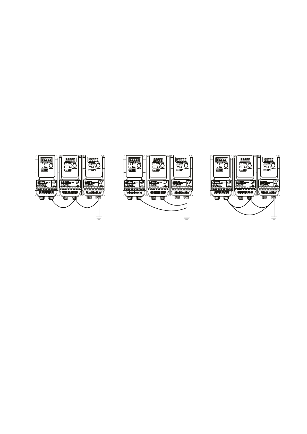
Inverter Ground terminal must be connected to installation ground correctly and
according to the required local wiring regulations.
Ground cable size must be according to the required local wiring
regulations. Ground connection should be as short as possible.
Do not share the ground of the inverter with other high current loads (Welding
machine, high power motors). Ground each unit separately.
Ensure that all ground terminals and connections are secure
Do not make ground loops when several inverters share a common ground point.
Note: Please leave at least 5cm while installing inverter side by side in order to provide
enough cooling space.
(a) Correct (b) Correct (c) Incorrect
Page 29
3-19
Sizes BDI50
1004
1007
2015
2022
Output Rating
Rated Output Capacity
kVA
1.0
1.65
2.9
4.0
Rated Output Current
A
2.6
4.3
7.5
10.5
HP
0.5 1 2
3
kW
0.4
0.75
1.5
2.2
Output Voltage
V
Three-Phase, 0 to 240V
Output Frequency
Hz
Based on parameter setting 0.01~599
Input Rating
Rated Voltage, Frequency
Allowable Voltage Fluctuation
+10% ~ -15%
Allowable Frequency Fluctuation
±5%
Input current
(1)
A
7.2
11
15.5
21
Allovable momentary
Enclosure
IP20
Sizes BDI50
1007
2015
2022
3037
4055
4075
Output Rating
Rated Output Capacity
kVA
1.65
2.90
4.00
6.67
9.91
13.34
Rated Output Current
A
4.3
7.5
10.5
17.5
26
35
HP 1 2 3 5
7.5
10
kW
0.75
1.5
2.2
3.7
5.5
7.5
Output Voltage
V
Three-Phase, 0 to 240V
Output Frequency
Hz
Based on parameter setting 0.01~599
Input Rating
Rated Voltage, Frequency
Three-Phase, 200V to 240V, 50/60Hz
Allowable Voltage Fluctuation
+10% ~ -15%
Allowable Frequency Fluctuation
±5%
Input current
(1)
A
6.4
9.4
12.2
19.3
28.6
38.5
Allovable momentary
Enclosure
IP20
3.4 Specifications
3.4.1 Product Specifications
230V Class : Single phase. F : Standards for built-in filter
Maximum Applicable Motor
power loss time
230V Class : Three phase
Single-Phase, 200V to 240V, 50/60Hz
s 1.0 1.0 2.0 2.0
Maximum Applicable Motor
power loss time
(1) The input current is calculated value at full rated output current.
s 1.0 2.0 2.0 2.0 2.0 2.0
Page 30
3-20
400V Class : Three phase. F : Standards for built-in filter
Sizes BDI50
2007
2015
2022
3037
3055
4075
4110
Output Rating
Rated Output Capacity
kVA
1.7
2.9
4.0
7.01
9.91
13.34
18.29
Rated Output Current
A
2.3
3.8
5.2
9.2
13.0
17.5
24
HP 1 2 3 5
7.5
10
15
kW
0.75
1.5
2.2
3.7
5.5
7.5
11
Output Voltage
V
Three-Phase, 0 to 480V
Output Frequency
Hz
Based on parameter setting 0.01~599
Input Rating
Rated Voltage, Frequency
Three-Phase, 380V to 480V, 50/60Hz
Allowable Voltage Fluctuation
+10% ~ -15%
Allowable Frequency
Input current
(1)
A
4.2
5.6
7.3
10.1
14.3
19.3
26.4
Allovable momentary
Enclosure
IP20
Maximum Applicable Motor
Fluctuation
power loss time
(1) The input current is calculated value at full rated output current.
s 2.0
2.0 2.0 2.0 2.0 2.0 2.0
±5%
BDI50 Powerloss
All inverters are equipped with internal fans (excluding BDI50 size 1):
Drive Model Power Loss (W) Heat Loss (kcal/hr)
230 V Class : single phase and three phase
BDI50-1004-...-2M/2T-… 27.0 23.2
BDI50-1007-...-2M/2T-… 45.0 38.7
BDI50-2015-...-2M/2T-… 64.0 55.0
BDI50-2022-...-2M/2T-… 70.0 60.2
BDI50-3037-...-2T-… 155.0 133.3
BDI50-4055-...-2T-… 148.0 127.3
BDI50-4075-...-2T-… 330.0 283.8
400 V Class: three phase
BDI50-2007-...-4-… 30.0 25.8
BDI50-2015-...-4-… 37.0 31.8
BDI50-2022-...-4-… 61.0 52.5
BDI50-3037-...-4-… 98.3 84.5
BDI50-3055-...-4-… 157.0 135.0
BDI50-4075-...-4-… 234.0 201.2
BDI50-4110-...-4-… 297.0 255.4
Page 31

3-21
3.4.2 General Specifications
Control Mode
V/f Control, Sensorless control (SLV)
Overload
150% * rated current (1’ every 10’).
Frequency
Output freq. Ra nge
0.01~599.00Hz
Speed accuracy
(100% torque)
3% (V/f)
1% (SLV)
Starting torque
3Hz / 100% (V/f)
3Hz / 150% (SLV)
Setting
Keypad : Set directly with
keys or the VR (Potentiometer
integrated)
External signal:
• by communication
Frequency limit
Lower and upper frequency limits
3 -skip frequency settings.
Run & Stop
Method
• Keypad
Main Controls
V / f curve s etting
6 fixed and one customized
Carrier frequency
1~16kHz (default 5kHz)
Acceleration and
2 sets Acc / dec time parameters
Multifunction digital
5, 19 functions
Sizes 3/4: NPN&PNP selection from terminals
Multifunction digital
output
1 relay, 16 functions
Multifunction analog
input
2, AVI: 0~10V/2~10V, ACI: 0~20mA/4~20mA
Multifunction analog
output
(0~10V), 5 functions
Main features
Autotune, Torque compensation, Slip compensation, 8 preset
Mechanical brake control, AVR function, Fan control
Info available
Parameter, parameter value, frequency, line speed, DC
Version, Fault Log
LED Status Indicator
For run/stop/forward and reverse.
Overload Protection
Integrated motor and Inverter overload protection.
Motor over-temperature
By PTC (AVI)
Overvoltage
200V Class : > 410V, 400V Class: > 820V
Undervoltage
200V Class: < 190V, 400V Class: < 380V
Auto-Restart
Inverter auto-restart after a momentary power loss.
Stall Prevention
Stall prevention for Acceleration/ Deceleration/ and
continuous Run.
▼▲
• AVI (0~10V / 2~10V), ACI (0~20mA, 4~20mA) input
• multifunction digital inputs
• Multifunction terminals (2/3 wire selection)
• Jog function
• By communication
deceleration control
input
Display
Protective
Functions
4 points S curve parameters
Sizes 1/2: NPN&PNP by separate models
speeds, Auto-run, PID control, torque boost, V/f starting
Frequency, Fault reset, Powerloss ride through, DC-brake,
voltage, output voltage, output current, PID feedback, input
and output terminal status, Heat sink temperature, Program
Page 32

3-22
Additional protective
Heatsink over temperature protection, Auto carrier frequency
operation, Auto restart attempts setting, Parameter lock
Environment
Specification
Protection degree
IP20
Operating temperature
-10~ +40°C (size 1), -10~+50°C (all other sizes)
Storage temperature
-20~60°C
Humidity
Under 95%RH ( no condensation)
Altitude
1000 meters or lower
Vibration
Under 20Hz, 1G(9.8m/s²); 20~50Hz 0.6G(5.88m/s²)
Communication Function
Built in: RS-485 with Modbus RTU / ASCII (standard RJ45
Optionals: Profibus, DeviceNet, CANopen, TCP/IP
Braking unit
Built-in on 3ph 400V Class and 3ph 200V Class from 3.7kW to
7.5kW
EMC filter
Built-in on –F version 1ph 200V Class and 3ph 400V Class
Certification
CE
In compliance with EN61800-3 (CE & RE) and EN61800-5-1
Note: Inverter can get the better grounding effect with grounding kit.
RoHS
Conformity to RoHS directive
cULus
UL508C
functions
reduction with temperature rise, Protection of reverse
connection), BACnet
(LVD)
Page 33

3-23
3.5 Standard wiring
(
MCCB
L1(L)
AC
source
S2
S3
S4
AO
3
+
250VAC/1A
(30VDC/1A)
T1
T2
T3
RB
RA
S5
L3(N)
(
ON-OFF
Surge
Suppressor
10V
AVI
ACI
GND
MC
Magnetic
Contactor
RS485
FWD (Run/Stop)
REV (Run/Stop)
Speed Control
External speed
potentiometer = 10 Kohm
or PID input
Induction
Motor
COM
MC
Thermal
relay
MC
S1
GND
0~10V
2
AO
+
-
Frequency
Indicator
0~10VDC
CON2
Thermal
relay
M
0~20mA
P
P'
2'
1
-
Relay
Output
Pin 1 to Pin 8
Ground
Inverter
output
Power
input
Analog
Output
Multifunction
Input
Terminals
Analog
Input
3.5.1 Single phase (NPN input)
200V: BDI50-1004-...-2M-N ... BDI50-2022-...-2M-N
Page 34

3-24
3.5.2 Single phase (PNP input)
(
MCCB
L1(L)
AC
source
S2
S3
S4
AO
3
+
250VAC/1A
(30VDC/1A)
T1
T2
T3
RB
RA
S5
L3(N)
(
ON-OFF
Surge
Suppressor
10V
AVI
ACI
GND
MC
Magnetic
Contactor
RS485
FWD (Run/Stop)
REV (Run/Stop)
Speed Control
Externa l spee d
potentiometer = 10 Kohm
or PID input
Induction
Motor
+24V
MC
Thermal
relay
MC
S1
GND
0~10V
2
AO
+
-
Frequency
Indicator
0~10VDC
CON2
Thermal
relay
M
0~20mA
P
P'
2'
1
-
Relay
Output
Pin 1 to Pin 8
Ground
Inverter
output
Power
input
Analog
Output
Multifunction
Input
Terminals
Analog
Input
200V: BDI50-1004--...-2M-P ... BDI50-2022-...-2M-P
Page 35

3-25
3.5.3 Three phase (NPN input)
(
MCCB
L1(L)
AC
source
S2
S3
S4
AO
3
+
250VAC/1A
(30VDC/1A)
T1
T2
T3
RB
RA
S5
L3(N)
(
ON-OFF
Surge
Suppressor
10V
AVI
ACI
GND
MC
Magnetic
Contactor
RS485
FWD (Run/Stop)
REV (Run/Stop)
Speed Control
External speed
potentiometer = 10 Kohm
or PID input
Induction
Motor
COM
MC
Thermal
relay
MC
S1
GND
0~10V
2
AO
+
-
Frequency
Indicator
0~10VDC
CON2
Thermal
relay
M
0~20mA
P
P'
2'
1
-
Relay
Output
Pin 1 to Pin 8
Ground
Inverter
output
Power
input
Analog
Output
Multifunction
Input
Terminals
Analog
Input
(
L2
230V: BDI50-1007-...-2T-N ... BDI50-2022-...-2T-N
Page 36

3-26
400V: BDI50-2007-...-4-N ... BDI50-2022-...-4-N
(
MCCB
L1(L)
AC
source
S2
S3
S4
AO
3
+
250VAC/1A
(30VDC/1A)
T1
T2
T3
RB
RA
S5
L3(N)
(
ON-OFF
Surge
Suppressor
10V
AVI
ACI
GND
MC
Magnetic
Contactor
RS485
FWD (Run/Stop)
REV (Run/Stop)
Speed Control
External speed
potentiometer = 10 Kohm
or PID input
Induction
Motor
COM
MC
Thermal
relay
MC
S1
GND
0~10V
2
AO
+
-
Frequency
Indicator
0~10VDC
CON2
Thermal
relay
M
0~20mA
P
P'
2'
1
-
Relay
Output
Pin 1 to Pin 8
Ground
Inverter
output
Power
input
Analog
Output
Multifunction
Input
Terminals
Analog
Input
(
L2
P
BR
Page 37

3-27
3.5.4 Three phase (PNP input)
(
MCCB
L1(L)
AC
source
S2
S3
S4
AO
3
+
250VAC/1A
(30VDC/1A)
T1
T2
T3
RB
RA
S5
L3(N)
(
ON-OFF
Surge
Suppressor
10V
AVI
ACI
GND
MC
Magnetic
Contactor
RS485
FWD (Run/Stop)
REV (Run/Stop)
Speed Control
External speed
potentiometer = 10 Kohm
or PID input
Induction
Motor
+24V
MC
Thermal
relay
MC
S1
GND
0~10V
2
AO
+
-
Frequency
Indicator
0~10VDC
CON2
Thermal
relay
M
0~20mA
P
P'
2'
1
-
Relay
Output
Pin 1 to Pin 8
Ground
Inverter
output
Power
input
Analog
Output
Multifunction
Input
Terminals
Analog
Input
(
L2
P
BR
400V: BDI50-2007-...-4-P-F ...BDI50-2022-...-4-P-F
Page 38

3-28
3.5.5 Three phase (NPN / PNP Selectable m odels)
(
MCCB
L1
AC
source
S2
S3
S4
AO
3
+
250VAC/1A
(30VDC/1A)
T1
T2
T3
RB
RA
S5
L3
(
ON-OFF
Surge
Suppressor
10V
AVI
ACI
GND
Magnetic
Contactor
RS485
FWD (Run/Stop)
REV (Run/Stop)
Speed Control
External speed
potentiometer = 10 Kohm
or PID input
Induction
Motor
COM:NPN
MC
Thermal
relay
MC
S1
GND
0~10V
2
AO
+
-
Frequency
Indicator
0~10VDC
CON2
Thermal
relay
M
0~20mA
P
P'
2'
1
-
L2
(
+24V:NPN *
RC
SC
COM:PNP
+24V:PNP
Power
input
P
BR
Inverter
output
Ground
Pin 1 to Pin 8
Multifunction
Input
Terminals
Relay
Output
Analog
Output
Analog
Input
400V: BDI50-3037-...-4-NP ... BDI50-4110-...-4-NP
230V: BDI50-3037-...-2T-NP ... BDI50-4075-...-2T-NP
NPN/PNP input type selection
PNP: 1. Link SC and COM terminal
2.Use +24v terminal for S1~S5 common point
NPN: 1.Link SC and +24V terminal
2.Use COM terminal for S1~S5 common point
Please ensure correct connection before setting parameter group 3 digital inputs.
Page 39

3-29
3.6 Terminal Description
Terminal symbols
TM1 Function Description
L1(L)
Main power input, single phase
L1(L) / L3(N)
three phase (400V):L1 / L2 / L3
L2
P*
BR*
T1
T2
T3
Ground terminal
L1(L) L2 L3(N) T1 T2 T3
L1(L) L2 L3(N) T1 T2 T3
L1 L2 L3 P BR T 1 T2 T3
3.6.1 Description of main circuit terminals
:
three phase(200V):L1(L) / L2 / L3(N)
L3(N)
externally connected braking resistor
Inverter output, connect to U, V, W terminals of motor
*P, BR for BDI50-…-KBX-2T / BDI50-…-KBX-4
Single phase
Note: the screw on L2 terminal is removed for the single phase input supply models.
Three phase (BDI50-…-KXX-2T, 200V series)
Three phase (BDI50-…-KBX-2T & BDI50-…-KBX-4 series)
Page 40

3-30
3.6.2 Description of control circuit terminal
Terminal symbols
TM2 Function Description
Signal Level
RA
RB
COM
S1~S5 (COMMON) 【NPN】
24V
S1~S5 (COMMON) 【PNP】
24 VDC, 4.5 mA, Optical coupling
(Max,voltage 30 Vdc,
Input impedance 6kΩ)
Built in Power for an external speed
potentiometer
Analog voltage input
(choose by parameter 04-00)
Analog current input
(choose by parameter 04-00)
Ω)
Multi function analog output terminal.
Maximum output 10VDC/1mA
AGND
Analog ground terminal
RA RB COM S1 S2
S3
S4 S5 10V AVI ACI AO AGND
RA RB +24V S1 S2 S3 S4 S5 10V AVI ACI AO AGND
Size 1 & Size 2
Relay output terminal 250VAC/1A (30VDC/1A)
±15%,Max output current 30mA
NPN:
PNP:
S1~S5
10V
AVI
ACI
AO
Multi-function input terminals
(refer to group 3)
Specification : 0 / 2~10 VDC
Specification : 0 / 4~20mA
isolation
10V (Max current:20mA)
0~10V (Input impedance 200kΩ)
0~20mA (Input impedance 499
0~10V (Max current 2mA)
Page 41

3-31
Size 3 & Size 4
Terminal symbols
TM1 Function Description
RA
RB
RC
Terminal
symbols
+24V
Common point of PNP input
NPN/PNP selectable termin al.
COM
voltage reference point for S1~S5
(Max,voltage30 Vdc,
Built in Power for an external speed
potentiometer (Max output : 20mA)
Analog voltage input/motor over
(choose by parameter 04-00)
Analog current input.
parameter 04-00)
Multi function analog output terminal.
Maximum output 10VDC/1mA
AGND
Analog ground terminal
+24V SC C OM S1 S2 S3 S4 S5 10V ACI AO AGND
RA RB RC
TM1 TM2
AVI
PTC
TM2 Function Description Signal Level
Relay output terminal, Specification: 250VAC/5A(30VDC/5A)
RA: Normally open RB: Normally close RC: common point
S1~S5
10V
AVI/PTC
ACI
AO
NPN/PNP:
NPN input: +24V&SC need to be shorted.
PNP input: COM&SC need to be shorted.
Multi-function input terminals
(refer to group3)
temperature protection signal input.
Specification: 0 / 2~10 VDC
Specification: 0 / 4~20mA (choose by
±15%,Max output current 30mA SC
24 VDC, 4.5 mA, Optical coupling
isolation
Input impedance 6kΩ)
10V,(Max current:20mA)
0~10V(Input impedance 200kΩ)
0~20mA(Input impedance 499Ω)
0~10V(Max current 2mA)
Page 42

3-32
3.7 Dimensions an d weight
D
D1
W1
W
W2
D2
E
E1
E2
H
H1
H2
H3
2-Q1
2-Q2
Dimension (mm)
BDI50-1004-…
BDI50-1007-…
Size 1
*: With Built-in EMC filter
Model
W W1 W2 H H1 H2 H3 D D1 D2 E E1 E2 Q1 Q2
72 63 61 141 131 122 114 141 136 128.2 86.3 81.1 55 4.4 2.2 0.9 (1*)
Weight
(kg)
Page 43

3-33
Size 2 200V
W
H2
W1
H1
D1
D
W2
H
2-Q1
2-Q2
D2
H3
E
E1
E2
Dimension (mm)
BDI50-2015-…-2M
BDI50-2015-…-2T
BDI50-2022-…-2M
BDI50-2022-…-2T
Model
W W1 W2 H H1 H2 H3 D D1 D2 E E1 E2 Q1 Q2
118 108 108 144 131 121 114 150 144.2 136.4 101.32 96.73 51.5 4.4 2.2
Weight
(kg)
1.4
(1.5*)
* : With Built-in EMC filter
Page 44

3-34
Size 2 400V
D1
D
W1
H
H1
H2
H3
W
W2
D2
E
E1
E2
2-Q1
2-Q2
BDI50-2007-…-4
BDI50-2022-…-4
Model
BDI50-2015-…-4
* : With Built-in EMC filter
W W1 W2 H H1 H2 H3 D D1 D2 E E1 E2 Q1 Q2
118 108 108 144 131 121 114 150 144.2 136.4 101.32 96.73 51.5 4.3 2.2
Dimension (mm)
Weight
(kg)
1.4
(1.5*)
Page 45

3-35
Size 3
H1
H
H2
D
D1
H3
W1
W
D2
E
E1
E2
2-Q
Dimension (mm)
W
W1 H H1
H2
H3 D D1
D2 E E1
E2
Q
Model
Weight
(kg)
BDI50-3037-…
129 118
BDI50-3055-…-4
197.5 177.6 188 154.7 148 143.7 136 102.6 96 48.2 4.5
* : With Built-in EMC filter
2,2
(2.4*)
Page 46

3-36
Size 4
W1
H1
D
W
D2
E
E1
D1
H2
H
H3
2-Q
W
W1 H H1
H2
H3 D D1
D2 E E1
Q
BDI50-4075-…
BDI50-4110-…
Model
BDI50-4055-…-2T
Dimension (mm)
187 176 273 249.8 261 228.6 190 185.6 177.9 136 84.7 4.5 6.3* (6.3*)
Weight
(kg)
* : With Built-in EMC filter
Page 47

3-37
3.8 EMC Filter Disconnection
EMC filter may be disconnected:
Inverter drives with built-in EMC filter are not suitable for connection to certain type of
supply systems, such as listed below; in these cases the RFI filter can be disabled.
In all such cases consult yo u r local elect rical standards requirements.
IT type supply systems (ungrounded) & certain supply systems for medi cal
equipment.
For ungrounded supply systems, if the filter is not disconnected the supply system
becomes connected to Earth through the Y capacitors on the filter circuit. This could
result in danger and damage to the Drive.
Size 1 & Size 2
Disconnection steps:
1. Remove EMC filter protection cover by screwdriver.
2. Remove EMC Filter link by pliers.
Note: Disconnecting the EMC filter link will disab les the filter function, please consult your local
EMC standards requirement.
① ②
Size 3 & Size 4
Disconnection steps:
1. Loosen the screws for EMC filter by screwdriver
2. Remove EMC filter
3. Tighten the screw
Note: Disconnecting the EMC filter link will disab les the filter function, please consult your local
EMC standards requirement.
Page 48

Chapter4 Software Index
Type
Item
Function
Frequency Display, Parameter, voltage, Current,
Temperature, Fault messages.
Hz/rpm: ON when the frequency or line speed is displayed.
the frequency is displayed.
Variable
Resistor
STOP/RESET
(Dual function keys)
STOP: Decelerate or Coast to Stop.
RESET: Use to Reset alarms or resettable faults.
▲
Increment parameter number and preset values.
▼
Decrement parameter number and preset values.
MODE
Switch between available displays
</ENTER
Dual function keys,
shift function, a long
function)
4.1 Keypad Descri ption
4.1.1 Operator Panel Functions
Digital
display &
LEDs
Keys
On Keypad
Main digital displays
OFF when the parameters are displayed.
FWD: ON while the inverter is running forward. Flashes
LED Status
FREQ SET Used to set the frequency
RUN RUN: Run at the set frequency.
(
a short press for left
press for ENTER
“<” Left Shift:
Used while changing the parameters or parameter values
ENTER:
Used to display the preset value of parameters and for saving
the changed parameter values.
while stopped.
REV: ON while the inverter is running reverse. Flashes
while stopped.
FUN: ON when the parameters are displayed. OFF when
4-1
Page 49

Digit
LED
Letter
LED
Letter
LED
Symbol
LED
0 A n
1
b o
2 C P
_
3 d q
.
4 E r
5 F S
6 G t
7 H u
8 J V
9 L Y
Actual output frequency
Set frequency
Digits are lit Continually
Preset digits flashing
Selected digit flashing
4.1.2 Digital display Description
Alpha numerical display format
-
°
Digital display indication formats
4-2
Page 50

Display
Description
LED Indicator light Status
Frequency / line
Hz/RPM
FUN
FWD
FWD
REV
REV
LED display examples
In stop mode shows the set frequency
In run mode shows the actual output frequency
Selected Parameter
Parameter Value
Output Voltage
Output Current in Amps
DC Bus voltage
LED Status description
speed Indicator
Menu mode indicator
FWD indicator
Temperature
PID feedback value
Error display
Analogue Current / Voltage ACID / AVI . Range ( 0~1000)
Hz/rpm
Fun
FWD
On
On while not displaying frequency or line speed
On while running
forward
FWD
Flashing while
stopped in
Forward mode.
REV indicator light
On while running
REV
reverse
REV
4-3
Flashing while
stopped in
Reverse mode
Page 51

MODE
2sec later
Power supply
frequency
parameter
MODE
12- 00
Display Mode
【0】:Disable display
【1】:output Current
【2】:output Volt a ge
【3】:DC voltage
【4】:Temperature
【5】:PID feedback
【6】:AVI
【7】:ACI
MODE
MODE MODE
2sec later
display:Power supply
Output Current
Set frequency
parameter
4.1.3 Digital display set up
On power up digital display screens will be as shown below.
User selectable display formats:
0 0 0 0 0
high
Low
Each of the above 5 digit s can be set to any of the selecti on s bel ow from 0 to 7
Range
The highest bit of 12-00 sets the power on the display , other bits set the se lected display from range
0-7.as Listed above.
Example1: Set parameter 12- 00=【10000】to obtain displ ay format shown below.
4-4
Page 52

Example 2. Set parameter 2: 12- 00=【12345】 to obtain the display format shown below.
MODE
MODE
2sec later
MODE
MODE
MODE
MODE
MODE
Temperature
< 4
>
PIDfeedback
< 5 >
Output Current
< 1
>
Parameter
DC voltage
< 3 >
Output Voltage
< 2 >
Set Frequency
Display
: Power supply
Short time press
Long time press
T1
T2
“</ENT”
short press for left shift
function
“</ENT”
long press for ENT
function
T1
T2
Increment/ Decrement key functions:
1.“
▲”/ “▼” :
Quick pressing of these keys will Increment or Decrement the selected digit by one.
Extended pressing will Increment or Decrement the selected digit continuously.
2.“</ENT” Key functions :
Quick pressing of this key will display the preset value of the parameter selected.
Extended pressing of this key will save the altered value of the selected parameter.
4-5
Page 53

4.1.4 Example of keypad operation
Short press
</ENT once
Short press
</ENT twice
Short press
once
Long press
</ENT once
Frequency
Short press
once
Long press
</ENT once
Short press
MODE once
▲
Example 1: Modifying Parameters
▲
4-6
Page 54

Example 2: Modifying the frequency from keypad in run and stop modes.
Modify frequency in stopping
Modify frequency in operating
2
sec later
2sec later
Short time press
</ENT once
Press RUN
5sec later
or long time press
</ENT once
Long time press
</ENT once
Without
pressing the
button
</ENT,
After 5
seconds to
return
Short time press
</ENT once
Power Supply
Power supply
Actual frequency
Actual frequency
Short time press
</ENT once
Short time press
</ENT once
Short time press
▲ once
Short time press
</ENT once
Short time press
</ENT once
Short time press
▲ once
Set frequency display Set frequency display
Modify bit<unit>
Modify bit<ten>
Modify bit<hundred>
Modify bit<hundred+1>
Modify bit<hundred+1>
Modify bit<hundred>
Modify bit<ten>
Modify bit<unit>
Modify frequency is stopping
Modify frequency is stopping
Power supply
Power supply
2sec later
2sec later
Set frequency display
Set frequency display
Press run
Short press
</ENT once
Short press
</ENT once
Actual frequency
Short press
</ENT once
Short press
</ENT once
Short press
</ENT once
Short press
</ENT once
Short press
▲
Short press
▲
5 sec later or
long press
</ENT once
Long press
</ENT once
Modify bit<unit>
Modify bit<unit>
Modify bit<ten>
Modify bit<ten>
Modify bit<hundred>
Modify bit<hundred>
Modify bit<hundred+1>
Modify bit<hundred+1>
Actual frequency
Without pressing
the button </ENT,
After 5 seconds to
return
once
Note: frequency command setting will be limited to the range set by parameters for lower &
upper frequency.
once
4-7
Page 55

4.1.5 Operation Control
4-8
Page 56

4.2 Programmable Parameter Groups
Parameter notes for Parameter Groups
*1
Parameter can be adjusted dur ing running mode
*2
Cannot be modified in communication mode
*3
Does not change with factory reset
*4
Read only
Parameter Group No.
Group 00 Basic parameters
Group 01 V/F Pattern selections & setup
Group 02 Motor parameters
Group 03 Multi function digital Inputs/Outputs
Group 04 Analog signal inputs/ Analog output
Group 05 Preset Frequency Selections.
Group 06 Auto Run(Auto Sequencer) function
Group 07 Start/Stop command setup
Group 08 Drive and motor Protection
Group 09 Communication function setup
Group 10 PID function setup
Group 11 Performance control functions
Group 12 Digital Display & Monitor functions
Description
Group 13 Inspection & Maintenance function
4-9
Page 57

Group 00- The basic parameters group
No. Description Range
Setting
0:V/F mode
1:SLV mode
0:Forward
1:Reverse
0:Keypad
1:External Run/Stop Control
2:Communication
0:Keypad
1:External Run/Stop Control
2:Communication
0: Forward/Stop-Reverse/Stop
1: Run/Stop-Reverse/Forward
2: 3-Wire Control Mode-Run/Stop
0: Frequency setting via ▼/▲ buttons
1:Potentiometer on keypad
2:External AVI Analog Signal Input
3:External ACI Analog Sign al Input
4:External Up/Down Frequency
Control
5:Communication setting Frequency
6:PID output frequency
0: Frequency setting via ▼/▲ buttons
1:Potentiometer on keypad
2:External AVI Analog Signal Input
3:External ACI Analog Sign al Input
4:External Up/Down Frequency
Control
5:Communication setting Frequency
6:PID output frequency.
Frequency
Frequency Command
Frequency command
(Communication mode)
1:Save the communication frequency
0:by Current Frequency Command
1:by 0 Frequency Command
2:by 00-11
Initial Frequency
Keypad mode
00-12
Frequency Upper Limit
0.01~599.00
50.00/60.00
Hz
00-13
Frequency Lower Limit
0.00~598.99
0.00
Hz
00-14
Acceleration Time 1
0.1~3600.0
10.0
s
*1
00-15
Deceleration Time 1
0.1~3600.0
10.0
s
*1
00-16
Acceleration Time 2
0.1~3600.0
10.0
s
*1
00-17
Deceleration Time 2
0.1~3600.0
10.0
s
*1
00-18
Jog Frequency
1.00~25.00
2.00
Hz
*1
00-19
Jog Acceleration Time
0.1~25.5
0.5
s
*1
00-20
Jog Deceleration Time
0.1~25.5
0.5
s
*1
Factory
Unit Note
00-00
00-01
00-02
00-03
00-04
00-05
Control mode
Motor rotation
Main Run
Source Selection
Alternative Run
Source Selection
Operation modes for
external terminals
Main Frequency
Source Selection
0
0 - *1
1 -
0 -
0 -
2 -
-
00-06
00-07
00-08
00-09
00-10
00-11
Alternative Frequency
Source Selection
Main and Alternative
Frequency Command modes
Communication
Save mode
Initial Frequency
Selection ( keypad mode)
0 -
0: Main Or Alternative Frequency
1: Main frequency+Alternative
0.00~599.00 Hz *4
0:Save the frequency before power
down
0.00~599.00 50.00/60.00 Hz
0 -
0 -
0 -
4-10
Page 58

Group 01- V/F Pattern selection & Setup
No. Description Range
Setting
01-00
Volts/Hz Patterns
1~7
1/4
-
200V:170.0~264.0
400V:323.0~528.0
01-02
Max Frequency
0.2 ~ 599.00
50.00/60.00
Hz
01-03
Max Frequency Voltage Ratio
0.0 ~ 100.0
100.0
%
01-04
Mid Frequency 2
0.1 ~ 599.00
2.50/3.00
Hz
01-05
Mid Frequency Voltage Ratio 2
0.0 ~ 100.0
10.0/6.8
%
01-06
Mid Frequency 1
0.1 ~ 599.00
2.50/3.00
Hz
01-07
Mid Frequency Voltage Ratio 1
0.0 ~ 100.0
10.0/6.8
%
01-08
Min Frequency
0.1 ~ 599.00
1.30/1.50
Hz
01-09
Min Frequency Voltage Ratio
0.0 ~ 100.0
8.0/3.4
%
Volts/Hz Curve Modification
(Torque Boost)
01-11
V/F start Frequency
0.00~10.00
0.00
Hz
No-load oscillation suppression
gain
Motor Hunting Prevention
Coefficient
Sizes 1/2
others: 0
01-15
Motor Hunting Prevention Limit
0~100.0
5.0
%
Auto-Torque Compensation
Filter Coefficient
0.1~1000.0
Auto-torque Compensation
Gain
Auto-torque Compensation
Frequency
Group 02- Motor parameters
Setting
02-00
Motor No Load Current
----
By motor nameplate
A
*4
Motor Rated Current
(OL1)
----
*4
02-02
V/F Slip Compensation
0.0 ~ 100.0
0.0
%
*1
02-03
Motor Rated Speed
----
By motor nameplate
rpm
*4
02-04
Motor Rated Voltage
----
By motor nameplate
Vac
*4
02-05
Motor Rated Power
0~22.0
By motor nameplate
kW
02-06
Motor Rated Frequency
0~599.0
By motor nameplate
1: Static auto tuning
0
02-08
Stator Resistor Gain
0~600
by series
02-09
Rotor Resistor Gain
0~600
by series
02-10
Reserved
02-11
Reserved
02-12
Reserved
SLV Slip
Compensation Gain
SLV Torque
Compensation Gain
Factory
Unit Note
01-01
01-10
01-12
01-13
01-14
01-16
01-17
V/F Max voltage
0 ~ 10.0 0.0 % *1
0.0~200.0 0 %
1~8192 800
Motor Hunting Prevention Gain 0~100
0~100 0 %
Based on 13-08 Vac
100V/200V series: 7
0.1 ms
%
01-18
1.30~5.00 2 Hz
No. Description Range
02-01
02-07
Motor Auto Tuning
0: Disable
Factory
By motor nameplate A
Unit Note
02-13
02-14
0~200 by series %
0~200 100 %
4-11
Page 59

Group 02- Motor parameters
No. Description Range
Setting
Low Frequency Torque
Gain
SLV Without Load Slip
Compensation Gain
SLV With Load Slip
Compensation Gain
SLV With Load Torque
Compensation Gain
SLV Slip
Compensation Select
0: Slip Compensation 1
2: Slip Compensation 2
Group 03- Multi function Digital Inputs/Outputs
Setting
/Stop
-
1:Reverse/Stop Command Or
REV/FWD
-
03-02
Multifunction Input Term. S3
2:Preset Speed 1 (5-02)
2
-
03-03
Multifunction Input Term. S4
3:Preset Speed 2 (5-03)
3
-
4:Preset Speed 4 (5-05)
6:Jog Forward Command
7:Jog Reverse Command
8:Up Command
9:Down Command
10:Acc/Dec 2
11:Acc/Dec Disabled
12:Main/Alternative Run Command
select
13:Main/Alternative Frequency
Command select
14:Rapid Stop ( Decel to stop)
15:Base Block
16:Disable PID Function
17:Reset
18:Auto Run Mode enable
03-05
Reserved
03-06
Up/Down frequency band
0.00~5.00
0.00
Hz
0:Preset frequency is held as the
function is disabled.
1:Preset frequency is reset to 0 Hz
as the inverter stops.
2:Preset frequency is held as the
available.
03-08
S1~S5 scan confirmation
1~200. Number of Scan cycles
10
ms
xxxx0:S1 NO xxxx1:S1 NC
xxx0x:S2 NO xxx1x:S2 NC
xx0xx:S3 NO xx1xx:S3 NC
x0xxx:S4 NO x1xxx:S4 NC
Factory
Unit Note
02-15
02-16
02-17
02-18
02-19
0~100 50 %
0~200 by series %
0~200 150 %
0~200 100 %
No. Description Range
03-00
03-01
Multifunction Input Term. S1
Multifunction Input Term. S2
0:Forward/Stop Command or Run
0
Factory
0
1
Unit Note
03-04
03-07
03-09
Multifunction Input Term. S5
Up/Down Frequency modes
S1~ S5 switch type select
17 -
inverter stops, and the UP/Down
0 -
inverter stops, and the UP/Down is
00000 -
4-12
Page 60

Group 03- Multi function Digital Inputs/Outputs
No. Description Range
Setting
0xxxx:S5 NO 1xxxx:S5 NC
03-10
Reserved
0:Run
1:Fault
2:Setting Frequency Reached
3:Frequency Reached (3-13±3-14)
4:Output Frequency Detection1(>
3-13)
5:Output Frequency Detection2(<
3-13)
6:Auto-Restart
7:Momentary AC Power Loss
8:Rapid Stop
9:Base Block
10:Motor Overload Protection(OL1)
11:Drive Overload Protection(OL2)
12:Reserved
13:Output Current Reached
14:Brake Control
15:PID feedback disconnection
detection
03-12
Reserved
level (Hz)
03-14
Frequency Detection band
0.00~30.00
2.00
Hz
*1
Output Current Detection
Level
Output Current Detection
Period
External Brake Release
level
External Brake Engage
Level
0:A (Normally open)
1:B (Normally close)
220/230V:380
415/460V:780
220/230V:360
415/460V:740
03-11
Output Relay(RY1)
Factory
1 -
Unit Note
03-13
03-15
03-16
03-17
03-18
03-19
03-20
03-21
※ “NO” indicates normally open, “NC” indicates normally closed.
Output frequency detection
Relay Output function type
Braking Transistor On
Level
Brake Transistor Off Level
0.00~599.00 0.00 Hz *1
0.1~999.9 0.1 A
0.1~10.0 0.1 s
0.00~20.00 0.00 Hz
0.00~20.00 0.00 Hz
200V: 240.0~400.0V
400V: 500.0~800.0V
200V: 240.0~400.0V
400V: 500.0~800.0V
0 -
380/400V:690
380/400V:650
VDC
VDC
4-13
Page 61

Group 04- Analog signal inputs/ Analogue output functions
Setting
AVI ACI
0:0~10V 0~20mA
1:0~10V 4~20mA
2:2~10V 0~20mA
3:2~10V 4~20mA
AVI Signal Ver ification
Scan rate
04-02
AVI Gain
0 ~ 1000
100
%
*1
04-03
AVI Bias
0 ~ 100
0 % *1
04-04
AVI Bias Selection
0: Positive 1: Negative
0 - *1
04-05
AVI Slope
0: Positive 1: Negative
0 - *1
ACI Signal Verification
Scan rate
04-07
ACI Gain
0 ~ 1000
100
%
*1
04-08
ACI Bias
0 ~ 100
0 % *1
04-09
ACI Bias Selection
0: Positive 1: Negative
0 - *1
04-10
ACI Slope
0: Positive 1: Negative
0 - *1
0: Output Frequency
4: Motor Current
(%)
(%)
0: Positive
1: Negative
0: Positive
1: Negative
setting
(offset) setting
(offset) signe selection
curve selection
No. Description Range
04-00
04-01
04-06
04-11
AVI/ACI analog Input
signal type select
Analog Output
mode(AO)
1~200 50 2ms
1~200 50 2ms
1: Frequency Command
2: Output Voltage
3: DC Bus Voltage
Factory
0 -
0 - *1
Unit Note
04-12
04-13
04-14
04-15
04-16
04-17
04-18
04-19
Analog Output AO Gain
Analog Output AO Bias
AO Bias Selection
AO Slope
Potentiometer /
frequency curve gain
Potentiometer /
frequency curve bias
Potentiometer /
frequency curve bias
Potentiometer /
frequency slope of the
0 ~ 1000 100 % *1
0 ~ 1000 0 % *1
0 - *1
0 - *1
0~1000 100 % *1
0~100 0 % *1
0: Positive
1: Negative
0: Positive
1: Negative
0 - *1
0 - *1
4-14
Page 62

Group 05- Preset Frequency Selections.
Setting
0: Common Accel/Decel
Accel/Decel 1 or 2 apply to all speeds
1: Individual Accel/Decel Accel/ Decel
speeds (Acc0/Dec0~ Acc7/Dec7)
Preset Speed 0
(Keypad Freq)
05-02
Preset Speed1 (Hz)
5.00
Hz
*1
05-03
Preset Speed2 (Hz)
10.00
Hz
*1
05-04
Preset Speed3 (Hz)
20.00
Hz
*1
05-05
Preset Speed4 (Hz)
30.00
Hz
*1
05-06
Preset Speed5 (Hz)
40.00
Hz
*1
05-07
Preset Speed6 (Hz)
50.00
Hz
*1
05-08
Preset Speed7 (Hz)
50.00
Hz
*1
~
05-16
05-17
Preset Speed0-Acctime
10.0
s
*1
05-18
Preset Speed0-Dectime
10.0
s
*1
05-19
Preset Speed1-Acctime
10.0
s
*1
05-20
Preset Speed1-Dectime
10.0
s
*1
05-21
Preset Speed2-Acctime
10.0
s
*1
05-22
Preset Speed2-Dectime
10.0
s
*1
05-23
Preset Speed3-Acctime
10.0
s
*1
05-24
Preset Speed3-Dectime
10.0
s
*1
05-25
Preset Speed4-Acctime
10.0
s
*1
05-26
Preset Speed4-Dectime
10.0
s
*1
05-27
Preset Speed5-Acctime
10.0
s
*1
05-28
Preset Speed5-Dectime
10.0
s
*1
05-29
Preset Speed6-Acctime
10.0
s
*1
05-30
Preset Speed6-Dectime
10.0
s
*1
05-31
Preset Speed7-Acctime
10.0
s
*1
05-32
Preset Speed7-Dectime
10.0
s
*1
No. Description Range
05-00
05-01
05-09
Preset Speed Control
mode Selection
0-7 apply to the selected preset
0.00 ~ 599.00
Reserved
Factory
0 -
5.00 Hz *1
Unit Note
0.1 ~ 3600.0
4-15
Page 63

Group 06- Auto Run(Auto Sequencer) function
No. Description Range
Setting
e Unfinished
(Continues to run from the unfinished
Auto _ Run Mode
frequency command 1
Auto _ Run Mode
frequency command 2
Auto _ Run Mode
frequency command 3
Auto _ Run Mode
frequency command 4
Auto _ Run Mode
frequency command 5
Auto _ Run Mode
frequency command 6
Auto _ Run Mode
frequency command 7
06-08
~
06-15
Auto_ Run Mode
running time setting 0
*1
Auto_ Run Mode
running time setting 1
*1
Auto_ Run Mode
running time setting 2
*1
Auto_ Run Mode
running time setting 3
*1
Auto_ Run Mode
running time setting 4
*1
Auto_ Run Mode
running time setting 5
*1
Auto_ Run Mode
running time setting 6
*1
Auto_ Run Mode
running time setting 7
*1
06-24
~
06-31
Auto_ Run Mode
running direction 0
Auto_ Run Mode
running direction 1
0: Disabled.
1: Single cycle.
(Continues to run from th
step if restarted).
2: Periodic cycle.
step if restarted).
3: Single cycle, then holds the speed of
final step to run.
(Continues to run from the unfinished
step if restarted).
4: Single cycle.
(Starts a new cycle if restarted).
5: Periodic cycle.
(Starts a new cycle if restarted).
6: Single cycle, then hold the speed of
final step to run
(Starts a new cycle if restarted).
06-00
Auto Run
(sequencer)
mode selection
Factory
0 -
Unit Note
06-01
06-02
06-03
06-04
06-05
06-06
06-07
06-16
06-17
06-18
06-19
06-20
0.00~599.00
0.0 ~ 3600.0
0.00 Hz *1
0.00 Hz *1
0.00 Hz *1
0.00 Hz *1
0.00 Hz *1
0.00 Hz *1
0.00 Hz *1
Reserved
0.0 s
0.0 s
0.0 s
0.0 s
0.0 s
06-21
06-22
06-23
06-32
06-33
0: Stop
1: Forward
2: Reverse
0.0 s
0.0 s
0.0 s
Reserved
0 -
0 -
4-16
Page 64

Group 06- Auto Run(Auto Sequencer) function
No. Description Range
Setting
Auto_ Run Mode
running direction 2
Auto_ Run Mode
running direction 3
Auto_ Run Mode
running direction 4
Auto_ Run Mode
running direction 5
Auto_ Run Mode
running direction 6
Auto_ Run Mode
running direction 7
Group 07- Start/Stop command setup
Setting
Loss and Restart
1: Momentary power loss and restart enable
Auto Restart Delay
Time
Number of Auto
Restart Attempts
0: Enable Reset Only when Run Command is
Off
Direct Running After
Power Up
0: Enable Direct run on power up
1: Disable Direct run on power up
07-05
Delay-ON Timer
1.0~300.0
1.0 s
DC Injection Brake
(Hz) In Stop mode
maximum output voltage
5
50
DC Injection Brake
In stop mode
0: Deceleration to stop
1: Coast to stop
DC Braking Level at
Start
DC Braking Time at
Start
Factory
Unit Note
06-34
06-35
06-36
06-37
06-38
06-39
No. Description Range
07-00
07-01
Momentary Power
0: Momentary Power Loss and Restart disable
0.0~800.0
0 -
0 -
0 -
0 -
0 -
0 -
Factory
0 s
0.0 s
Unit Note
07-02
07-03
07-04
07-06
07-07
07-08
07-09
07-10
07-11
Reset Mode Setting
Start Frequency
DC Injection Brake
Level (%) In stop
mode
Time (Seconds)
Stopping Method
0~10
Off
1: Enable Reset when Run Command is On or
0.10 ~ 10.00
0 ~ 20 (Sizes 1/2). Based on the 20% of
0 ~ 100 (Sizes 3/4) based on the rated current
0.0 ~ 25.5
0~100
0.0~25.5
0 -
0 -
1 -
1.5 Hz
%
0.5 s
0
0 %
0.0 s
4-17
Page 65

Group 08- Drive & Motor Protection functions
Setting
xxxx0: Enable Trip Prevention During
in Run Mode
Trip Prevention Level
During Acceleration (%)
Trip Prevention Level
During Deceleration (%)
Trip Prevention Level In
Run Mode (%)
Over voltage Prevention
Level in Run Mode
230V: 350.0~390.0
400V: 700.0~780.0
xxxx0: Disable Electronic Motor
Overload Protection
xxxx1: Enable Electronic Motor
Overload Protection
xxx0x: Motor Overload Cold Start
xxx1x: Motor Overload Hot Start
xx0xx: Standard Motor
xx1xx: Invertor Duty Motor ( Force
Vent)
0: Coast-to-Stop After Overload
Protection is Activated (OL1)
3: Disabled
0: AVR function enable
1: AVR function Disable
2: AVR function disable for stop
3: AVR function disable for
deceleration
4: AVR function disable for stop and
deceleration.
5: When VDC>(360V/740V), AVR
deceleration.
Input phase lost
protection
0: Disabled
1: Enabled
No. Description Range
Acceleration
xxxx1: Disable Trip Prevention During
Acceleration
xxx0x: Enable Trip Prevention During
Deceleration
xxx1x: Disable Trip Prevention During
08-00
08-01
08-02
08-03
Trip Prevention Selection
xx0xx: Enable Trip Prevention in Run
xx1xx: Disable Trip Prevention in Run
x0xxx: Enable over voltage Prevention
x1xxx: Disable over voltage Prevention
50 ~ 200 by series
50 ~ 200 by series
50 ~ 200 by series
Deceleration
Mode
Mode
in Run Mode
Factory
00000 -
Unit Note
Inverter
Rated
Current
100%
08-04
Electronic Motor
08-05
08-06
08-07
08-08
Overload Protection
Operation Mode
Operation After
Overload Protection is
Activated
Over heat Protection
(cooling fan control)
AVR Function
(Auto Voltage
Regulation)
Protection is Activated
1: Drive Will Not Trip when Overload
0: Auto (Depends on temp.)
1: Operate while in RUN mode
2: Always Run
380.0/760.0 VDC *1
00001 -
0 -
1 -
4 -
08-09
08-10
PTC Overheat Function
function disable for stop and
0 -
0: Disable 0
1: Decelerate to stop
4-18
Page 66

Group 08- Drive & Motor Protection functions
No. Description Range
Setting
3: Continue running, when warning
level is reached.
PTC Signal Smoothing
Time
PTC Detection Time
Delay
PTC Detection Level
Reset
Fan Control Temperature
Level
08-17
Over current protection
level
0.0 ~ 60.0
0.0
A
08-18
Over current protection
time
0.0 ~ 1500.0
1.0
s
0: Motor Overload Protection Level 0
2: Motor Overload Protection Level 2
Group 09- Communication function setup
Setting
Station Number
0:Modbus RTU code
2:BACnet
3:38400
1:2 Stop Bits
2:With Odd Parity
Selection
1: 7-Bits Data
detection time
0: Deceleration to stop (set by 00-15:
3: continue operating
2: Coast to stop
Factory
Unit Note
08-11
08-12
08-13
08-14
08-15
08-16
08-19
level is reached.
Coast to stop, when protection
0.01~10.00 0.2 s
1~300 60 s
PTC Protection Level 0.1~10.0 0.7 V
0.1~10.0 0.3 V
PTC Warning Level 0.1~10.0 0.5 V
10.0~50.0 50.0
Motor Overload
Protection Level
1: Motor Overload Protection Level 1
°C
0
No. Description Range
09-00
09-01
09-02
09-03
09-04
09-05
09-06
Assigned Communication
Communication Mode
Select
Baud Rate Setting
(bps)
Stop Bit Selection
Parity Selection
Data Format
Communication time-out
1 ~ 32 1 - *2*3
1:Modbus ASCII code
0:4800
1:9600
2:19200
0:1 Stop Bit
0:Without Parity
1:With Even Parity
0: 8-Bits Data
0.0 ~ 25.5
Factory
0 - *2*3
2 bps *2*3
0 - *2*3
0 - *2*3
0 - *2*3
0.0 s
Unit Note
09-07
Communication time-out
operation selection
Deceleration time 1)
1: Coast to stop
2: Deceleration to stop (set by 00-17:
Deceleration time 2)
4-19
0 -
Page 67

09-08
Error 6 verification time
0 ~ 20
3
09-09
delay Time(ms)
09-10
BACnet stations
1~254 1
Group10- PID function Setup
Setting
5: Preset frequency
0: Potentiometer on Keypad
3: Communication Sett ing Fr equency
10-02
PID Target (keypad input)
0.0~100.0
50.0
%
*1
0:Disabled
Reverse Characteristic.
Coefficient
10-05
Proportional Gain
0.0 ~ 10.0
1.0
%
*1
10-06
Integral Time
0.0 ~ 100.0
10.0
s
*1
10-07
Derivative Time
0.00 ~ 10.00
0.00
s
*1
1: Negative
10-09
PID Offset Adjust
0 ~ 109
0 % *1
Time
0: Disabled
After Feedback Loss
Feedback Loss Detection
Level
Feedback Loss Detection
Delay Time
10-14
Integration Limit Value
0 ~ 109
100
%
*1
Drive Transmit
5 ~ 65
5 2ms
No. Description Range
0:Potentiometer on Keypad
1: Analog Signal Input. (AVI)
2: Analog Signal Input. (ACI)
3: Frequency set by communication
4: Keypad Frequency parameter 10-02
1: Analog Signal Input. (AVI)
2: Analog Signal Input. (ACI)
1: Deviation D Control.
FWD Characteristic.
2: Feedback D Control
FWD Characteristic.
3: Deviation D Control
Reverse Characteristic.
4: Feedback D Control
Reverse Characteristic.
5: Frequency Command + Deviation D Control.
FWD Characteristic.
6: Frequency Command + Feedback D Control
FWD Characteristic.
7: Frequency Command + Deviation D Control
Reverse Characteristic.
8: Frequency Command + Feedback D Control
10-00
10-01
10-03
PID target value selection
(when 00-05\00-06=6,
this function is enabled)
PID feedback value
selection
PID Mode Selection
Factory
1 - *1
2 - *1
0 -
Unit Note
10-04
10-08
10-10
10-11
10-12
10-13
Feedback Gain
PID Offset
PID Output Lag Filter
Feedback Loss Detection
Mode
0.00 ~ 10.00 1.00 % *1
0: Positive
0.0 ~ 2.5 0.0 s *1
1: Enabled - Drive Continues to Operate After
Feedback Loss
2: Enabled - Dri ve "STOPS"
0 ~ 100
0.0 ~25.5
4-20
0 - *1
0 -
0 %
1.0 s
Page 68

Group10- PID function Setup
No. Description Range
Setting
Allowable Integration
(1unit = 1/8192)
PID Sleep Frequency
Level
PID Sleep Function Delay
Time
PID Wake up frequency
Level
PID Wake up function
Delay Time
Max PID Feedback
Setting
10-22
Min PID Feedback Setting
0 ~999
0 - *1
Group11- Performance Control functions
Setting
1: Reverse command is disabled
11-01
Carrier Frequency (kHz)
1~16 5 KHz
2: Mode2, random PWM modulation
rise
11-04
S-Curve Acc 1
0.0 ~ 4.0
0.00 s
11-05
S-Curve Acc 2
0.0 ~ 4.0
0.00 s
11-06
S-Curve Dec 3
0.0 ~ 4.0
0.00 s
11-07
S-Curve Dec 4
0.0 ~ 4.0
0.00 s
11-08
Skip Frequency 1
0.00 ~ 599.00
0.00
Hz
*1
11-09
Skip Frequency 2
0.00 ~ 599.00
0.00
Hz
*1
11-10
Skip Frequency 3
0.00 ~ 599.00
0.00
Hz
*1
Skip Frequency
Bandwidth (±)
11-12
Reserved
Regeneration Prevention
0: Disable
2: Enable (during constant speed only)
Regeneration Prevention
Voltage Level
200V: 300.0~400.0
400V: 600.0~800.0
Regeneration Prevention
Frequency Limit
Regeneration Prevention
Voltage Gain
Regeneration Prevention
Frequency Gain
Speed loop proportion
gain
Factory
Unit Note
10-15
10-16
10-17
10-18
10-19
10-20
10-21
Integral Value Resets to
Zero when Feedback
Signal Equals the Target
Value
Error Margin (units)
0:Disabled
1: 1 Second
30: 30 Seconds (0 ~ 30)
0 ~ 100
0.00~599.00
0.0 ~25.5
0.00 ~ 599.00
0.0 ~ 25.5 0.0 s
0 ~999
No. Description Range
Factory
0 -
0 -
0.00 Hz
0.0 s
0.00 Hz
100 - *1
unit Note
11-00
11-02
11-03
11-11
11-13
11-14
Reverse operation control
Carrier mode Selection
Carrier Frequency
Reduction by temperature
Function
0: Reverse command is enabled
0: Mode0, 3ph PWM modulation
1: Mode1, 2ph PWM modulation
0: disabled
1: enabled
0.00 ~ 30.00 0.00 Hz *1
1: Enable
0 -
1 -
0 -
0 -
380/760 V
11-15
11-16
11-17
11-18
0.00~15.00 3.00 Hz
0~200 100 %
0~200 100 %
0~65535 10000
4-21
Page 69

11-19
Speed loop integration
gain
Speed loop differential
gain
0: Enable Stop Key when Run
Command not from Keypad
Group12 Digital Display & Monitor functions
Setting
00000 ~77777.
Each digit can be set to 0 to 7
0: Default display
(frequency¶meters)
1:Output Current
2:Output Voltage
3:DC voltage
4: Heatsink Temperature
5:PID feedback
6:Analog Signal Input. (AVI)
7:Analog Signal Input. (ACI)
0: Integer (xxx)
1:One decimal Place (xx.x)
2:Two Decimal Places (x.xx)
0:xxx--
1:xxxpb (pressure)
2:xxxfl (flow)
Custom Units (Line
Speed) Value
0:Drive Output Frequency is Displayed
1:Line Speed. Integer.(xxxxx)
2:Line Speed..One Decimal Place
(xxxx.x)
3:Line Speed.Two Decimal Places
(xxx.xx)
4:Line Speed.Three Decimal Places
(xx.xxx)
S1 S2 S3 S4 S5
RY1
12-06
Output Power
----
0.0
kW
Motor Current
Percentage
----
0 ~65535 800
11-20
11-21 Stop Key Selection
0 ~65535 0
Command
not from Keypad
1: Disable Stop Key when Run
No. Description Range
12-00
Extended Display Mode
0
Factory
00321 - *1
Unit Note
12-01
12-02
12-03
12-04
12-05
PID Feedback Display
format
PID Feedback Display
Unit Setting
Custom Units (Line
Speed) Display Mode
Inputs and output
Logic status display
( S1 to S5) & RY1
0 - *1
0 - *1
0~65535 1500/1800 rpm *1
0 - *1
----- - *4
12-07
0 %
4-22
Page 70

Group 13 Inspection & Maintenance functions
Setting
Drive Horsepower
Code
13-01
Software Version
---- - -
*3*4
Fault Log
(Last 3 Faults)
Accumulated Operation
Time1 1
Accumulated Operation
Time1 2
Time Mode
0:Time Under Power
1:Run Mode Time Only
0: Enable all Functions
3: Disable All Function
13-07
Parameter Lock Code
00000~65535
00000
-
1150: Reset to factory setting.
(60Hz,230V/400V)
No. Description Range
13-00
13-02
13-03
13-04
13-05
13-06
13-08
Accumulated Operation
Parameter Lock
Restore Factory
Settings
---- - - *3
---- - - *3*4
0~23 - hour *3
0~65535 ---- day *3
1: Preset speeds 05-01~05-08 cannot
be changed
2: All Functions cannot be changed
Except for Preset speeds
05-01~05-08
(50Hz,220V/380V)
1160: Reset to factory setting.
(60Hz,220V/380V)
1250: Reset to factory setting.
(50Hz,230V/400V)
1260: Reset to factory setting.
(60Hz,230V/460V)
1350: Reset to factory setting.
(50Hz,220V/415V)
1360: Reset to factory setting.
Factory
0 - *3
0 -
1250/1360
(*)
unit Note
-
(*) Notes:
For built-in EMC filter models, the d efault setting of 13-08 is “1250”.
For without built-in EMC filter models, the default setting of 13-08 is “1360”
4-23
Page 71

4.3 Parameter F unction Description
00- Basic parameter gr ou p
00- 00
Control mode
【0】:
【1】: SLV mode
00- 01
Motor Direction Control
【0】
【1】
00- 02
Main Run Comma nd S ource selection
00- 03
Alternative Run Command Source selection
【0】
【1】
【2】
00- 04
Operation modes for external terminals
【0】
【1】
【2】
Range
Select the relevant control mod e for the application, using parameter 00-00 Control mode.
Default control mode is V/F.
V/F mode can be used for most applications s pecifically multi-motor
or applications where auto t une is not s uccessful
or when a customized V/F pattern may be required.
Several V/f patterns are a vailable selectable by param et er 01-00.
Select the appropriate V/ f pat t er n based on the application load t ype and the motor base
frequency of 50 or 60 Hz.
For selections of the V/f p atterns. Refer to description of parameter 01-00
SLV ( Sensor less vector) is used for obtaining best performance from a mo t or . Speci ally at low
speeds or for applications with dynamic speed chan ge.
Range
00 - 01 Is valid in key pad mode only.
※Note: When Reverse function is disab led by parameter 11- 00= 1 setting 00-01 to 1 .” LOC” w ill be
displayed
V/F mode
: Forward
: Reverse
: Keypad
Range
Parameter 00 - 02/00- 03 sets the inverter operation command source. For switching between
00-02 and 00-03, use any of the external inputs S1 to S5 and set the relevant parameters (0300~03-04) to [12]. refer to parameter group3.
Range
Parameter 00-04 sets the function of the “External Run/ St op” and it is used in conjunct ion
with Parameters:
00-02 (Main Run Source) = 1 (Ext er nal R un/ St op)
Or
00-03 (Alternative Run source) = 1 ( Ext er nal Run /Stop)
And
: External Run/ Stop Control
: Communication
: Forward/stop-reverse/stop
: Run/stop-forward/reverse
: 3-wire control mode -run/stop
4-24
Page 72

Parameters 03-00 to 03-04 which are used to set the required function for the digital inputs
[S1 to S5 (multi-function inputs)].
※Note 1: Parameters 03-00 to 03-0 4 ar e O nly Required for External Run/stop (Two wire control
mode).
※Note 2: For External Run /Stop cont r ol, set parameters in the follow ing order:
1. 00-02 Or 00-03
2. 00-04
3. 03-00 to 03-04 as required. Not required for Three wire contro l mode.
00-04 = 0 (Forward/stop-reverse/stop)
Two external switches are r equired: one for Forward directi on and the other for Reverse.
Switch type: Two position, ma intained type (this is two wire m ode) .
1. Forward (Run/ Stop) Switch
Select one of the multifunct ion i nput s [S1 to S5] and set t he r elev ant parameter 03-00 to 03-04=0
0 = Forward - Run /Stop mode.
2. Reverse (Run /Stop) Switch
Select one of the multifunct ion i nput s [S1 to S5] and set the relevant parameter 03-00 to 03-04=1
1 = Reverse - Run /Stop mode.
00-04 =1 (Run/stop-forward/reverse)
Two external switches are r equired.
Switch type: Two position, ma intained type (this is two wire m ode) .
1. Run/Stop switch
Select one of the multifunction inputs [S1 to S5] and set the relevant parameter 03-00 to 03-04=0
0 = Run/Stop mode.
2. Forward/Reverse Switch
Select one of the multifunction inputs [S1 to S5] and set the relevant parameter 03-00 to 03-04=1
1 = Forward / Reverse direction selection.
Switch in OFF position = Forward direction
Switch in ON p o s ition = Revers direct ion.
00-04 = 2 (Three Wire Control mode R un/Stop)
In this mode Two Separate mo m ent ar y Push buttons are used for St ar t and stop functions.
In this mode parameter group 3 f or S1 t o S5 are not effective. S1,S 2 & S3 are allocated
automatically.
※Note 1: For S1 to initiate the Run command. Push button connect ed to S2 must be connecte d
by a normally closed type contact ( NC).
4-25
Page 73

00- 05
Main Frequency Comm and Source Selection
00- 06
Alternative Frequency Command Source Selection
【0】
: UP/DOWN of Keypad
【1】
【2】
【3】
【4】
【5】
【6】
00- 07
Main and Alt e r nat ive Frequency Command Modes
【0】
【1】
00- 08
Communication Frequency Command
Range
【
00- 09
Frequency Com m and save on po wer down (Comm unication mod e)
【0】
【1】
【1】
00-10
Initial Frequency Selection
【0】
【1】
【2】
00-11
Initial Frequenc y Setpoint
Range
【0.00~599.00】Hz
: Potentiomet er on Key pad
: External AVI Analog Signal Input
Range
: External ACI Analog Signa l Input
: External Up/ D own Frequency Cont rol
: Communication setting Frequency
: PID Output frequency
When 00-06 =[6], frequency com ma nd source is output of the PID.
: Main Or Alternative Frequency.
Range
: Main frequency + A lternat i ve Frequency
When 00-07=【0】, the frequency source is set by the Main fre quency parameter 00-05 (Default)
or by the Alternative frequency parameter 00-06.
Use any of the external terminals S1 to S5 and set the relevant parameter 03-00 to 03-04 =【13】to
switch from main to Alternative source.
Whe n 00 - 07 =【1】The Frequency com mand will be the SUM of Main & alternative frequencies.
I.e:
Main frequency setting=10Hz
Alternative frequency setting= 5Hz
If 00-07=0, frequency setting will be 10Hz OR 5 Hz
If 00-07=1, frequency setting will be 10Hz + 5 Hz = 15Hz
0.00~599.00】Hz
This parameter can be used to read the set frequency in communication mode
This parameter is only effective in the commun ication mode.
: disable
Range
: enable
00-09=【0】 Keypad frequency is sav ed.
00-09=
Frequency set by comm uni cat ion is saved.
: By Current Freq Command
Range
: By Zero Freq Command
: By 00-11
This parameter is only effective in keypad mode. .
4-26
Page 74

When 00-10=【0】,the initial frequency will be current frequency.
00-12
Frequency Upper limit
Range
【
00-13
Frequency Lower limit
Range
【
Frequency upper limit
Frequency Lower limit
0
Hz
T
00-14
Acceleration time 1
Range
【
00-15
Deceleration time 1
Range
【
00-16
Acceleration time 2
Range
【
00-17
Deceleration time 2
Range
【
(00-
15)x
(set frequency-the minimum starting frequency)
Actual acceleration time=
(
00-14)x(set frequency-the minimum starting frequency)
V/F Maximum output frequency
Actual deceleration time=
V
/F Maximum output frequency
When 00-10=【1】,the initial frequency will be 0.
When 00-10=【2】,the initial frequency will be as se t by parameter 00-11.
0.01~599.00】Hz
0.00~598.99】Hz
When 00-13 = 0 and frequency command is 0Hz, inverter output stays in zero speed.
When 00-13 > 0 an d frequency command ≤ setting in 00-13, inverter output speed = setting in 00-13
0.1~3600.0】 s
0.1~3600.0】s
0.1~3600.0】s
0.1~3600.0】s
Preset Acceleration and Deceleration times by abov e parameters are the time taken for the out put
frequency to ramp up or ram p dow n between the Upper and the lower V/F frequency limits.
Actual acceleration and deceleration time is ca lculated as follows:
V/F mode:
SLV mode:
4-27
Page 75

(00-15)x(set frequency
-the minimum starting frequency
)
Actual acceleration time
=
(00-14)x(set frequency-the minimum starting frequency)
Motor rated frequency
Actual deceleration time=
Motor rated frequency
V/F Maximum output
Frequency or motor rated
frequency
Set frequency
Acc-time 00-14
Dec-time 00-15
Actual acc-time
Actual dec-time
Hz
T0
The minimum starting
frequency
00-18
Jog Frequency
【
00-19
Jog Acceleration Time
【
00-20
Jog Deceleration Time
【
V/F Maximum output frequency is for VF curve, which can be checked from table when VF curve is
fixed. Maximum output frequency is 01-02 when VF curv e is customized, or motor rated frequency
02-06
Range
Range
Range
The JOG function is operational by using the multi-function input terminals S1 to S5 and setting
the relevant parameters 03-00~03-04 to 【6】JOG FWD or【7】JOG REV. Refer to parameter
group 3.
1.00~25.00】Hz
0.1~25.5】s
0.1~25.5】s
4-28
Page 76

01-V/F command group
01- 00
Volts/Hz Patterns (V/F)
Range
【
1~7】
Function
General Use
【
】
100
B
C
1.3 2.5 50
(V)%
Hz599
【
】
High start
torque
【
】
100
B
C
1.32.5 50
(V)%
Hz599
【
】
Decreasing torque
【
】
100
B
C
1.3 25 50
(V)%
Hz599
【
】
Sizes 1/2
Sizes 3/4
B(Xb)
C(Xc)
B(Xb)
C(Xc)
2/5
12%
9.5%
6.9%
3.5%
3/6
25%
7.7%
40%
3.4%
100
B
C
1.5 30 60
(V
)%
Hz599
Set 01-00 to one of the following preset V/f selecti ons 【1~6】according to the require d application.
Parameters 01-02~01-09 Can not be modified (read only ).
Six fixed V/f patter ns are show n below.【1~3】for 50 Hz systems and 【4~6】for 60 Hz.
TYPE
01-
00
=
1
=
2
50Hz 60Hz
V/F pattern
01-
00
V/F pattern
=
4
=
5
=
3
(V) 100% is the maximum output voltage. B, C point pr eset % settings will be as tabl e bel ow:
01- 00
Setting 01-00 =[7] provides a flexible V/F curve which can be selected by experienced users by
setting parameters (01-02~01-09).
=
6
1/4 10% 8% 6.8% 3.4%
4-29
Page 77

01- 01
V/f Maximum voltage
Range
200:【170.0~264.0】V
400:【323.0~528.0】V
01- 02
Maximum Freque ncy (base frequency)
Range
【
01- 03
Maximum Frequency Voltage Ratio
Range
【
01- 04
Medium Frequency 2
Range
【
01- 05
Medium Frequency V ol tage Ratio 2
Range
【
01- 06
Medium Frequency 1
Range
【
01- 07
Medium Frequency V ol tage Ratio 1
Range
【
01- 08
Minimum Freq uency
Range
【
01- 09
Minimum Freq uency Voltage Ratio
Range
【
01-10
V ol ts /Hz Curv e Mo dif ica t ion (Torque Boost)
Range
【
0.2 ~ 599.00】Hz
0.0 ~ 100.0】%
0.1 ~ 599.00】Hz
0.0 ~ 100.0】%
0.1 ~ 599.00】Hz
0.0 ~ 100.0】%
0.1 ~ 599.00】Hz
0.0 ~ 100.0】%
Max output frequency depends on parameter 01-00 , for 01-00=【7】It can be set by parameter
01-02.
For 01-00 ≠【7】, t he ma ximum output frequency depends on parameter 00-12, frequency
upper limit.
0 ~ 10.0】%
Inverter output V / F curve settings for points B, C ca n be adjusted by parameter 01-10 to
improve the output torque.
Calculation of B, C point voltage: B point voltage = X b × maxim um output voltage, C point
voltage = Xc × maximum out put voltage (Xb, Xc see 01-00). When 01-10 = 0, the torque
improvement is disabled.
4-30
Page 78

100
B
C
1 2.5/3.0 50/60
(V)%
Hz
01-10
01-11
V/F start Frequency
Range
【
01-12
No-load oscillation supp ressio n gain
Range
【0.0~200.0】%
01-13
Motor Hunting Prevention Coefficient
Range
【1~8192】
01-14
Motor Hunting Prevention Gain
Range
【0~100】%
01-15
Motor Hunting Prevention Limit
Range
【0.0~100.0】%
01- 16
Auto-Torque Compensation Filter Coefficient
Range
【0.1 ~ 1000.0】ms
01- 17
Auto-torque Compensation Gain
Range
【0~ 100】%
01- 18
Auto-torque Compensation Frequen cy
Range
【1.30 ~ 5.00】Hz
01-13
01-14
01-15
0.00 ~10.00】Hz
VF Start Frequency is for occasion where Start Frequency higher than zero Hz is needed.
In V/F mode , If in no load cond ition current osc illat ion occ urs c ausi ng motor vibrat ion t hen adj ust
parameter 01-12 to reduce this effect.
Adjustment can be done in steps of 5 to 10%.
In V/F mode, parameters 01-13,01-14 & 01-15 are used t o prevent motor hunting by adjusting the
V/F output voltage level.
01-13 Sets the hunting prevention response time constant (in msecs).
01-14 Sets the Gain of the hunting prevention.
01-15 Sets the hunting prevention voltage limit.
Diagram below shows the Parameter relationships.
Auto-torqu e Com pensat io n funct ion is effective in V/F mode. I t can be used t o correct insuf ficient
torque at low frequencies ( below 5 hz)
Parameters 01-16 to 01-18 are effective after carryi ng out Auto tune function in SL V mode.
Setting 01-17=0 Disables the auto torque compensation function.
4-31
Page 79

1
5
50/60
Gain (%)
01-17
Hz
Auto compens at ion Frequency (Hz)
01-18
4-32
Page 80

02- Motor parameter group
02- 00
Motor no load curr ent. (For slip compensation calculation)
Range
----
02- 01
Motor Rated Current
Range
----
02- 02
Slip Compensation Gain. (V/f mode onl y)
Range
【
Slip compensation boost=
Output Current-(02-00)
(02-01)-(02-00)
x(02-02)xRate motor slip
(02-02)approximate Value=
Motor synchronization speed-Rated speed
Motor synchronization speed
120
4
Example: 4 poles, 60Hz induction motor synchronization speed= x 60=1800(RPM)
02- 03
Motor Rated Speed
Range
----
02- 04
Motor Rated Voltage
Range
----
※Note: Please set the value according to motor’s nameplate.
0.0 ~ 100.0】(%)
When the load causes the actual motor speed to be reduced below the speed set by
inverter output frequency (Slip) , parameter 02-02 Slip compensation can be used to correct
the speed.
Slip compensation calculation in V/F mode:
Motor slip = Motor synchronous speed- Motor Rat ed Sp eed
※Note: Parameters 02- 00/02- 01 have to be set according to the specific motor data and in
relation to the Inverter rating model parameter (13- 00).
Slide compensation limit, inverter will calculate the motor slide according to 02-03. V/F slide
compensation will not be higher than 02-03.
※Note: Please set the value according to motor’s nameplate.
In order to prevent the output voltage of inverter is too high. The output voltage value will not
be higher than 02-04. 02-04 can be changed during operation.
※Note: Please set the value according to motor’s nameplate.
4-33
Page 81

02- 05
Motor Rated Power
Range
【0~22.0】kW
02- 06
Motor Rated Frequency
Range
【0~599.0】Hz
02- 07
Motor Auto Tuni ng
【0】: Disable
【1】: Static auto tuning
02- 08
Stator Resistor Gain
Range
----
02- 09
Rotor Resistor Gain
Range
----
02- 13
SLV Slip Compensation Gain
Range
【0~200】%
02- 14
SLV Torque Compensation Gai n
Range
【0~200】%
02- 15
Low Frequency Torque Gain
Range
【0~100】%
Range
When inverter executes auto tuning function, Fmax value sets by 02-06.
When inverter does not execute auto tuning function, Fmax value sets by 01-02.
Auto tune function in SLV mode. 00-00=【1】
Set motor parameters 02-01 and 02-03~02-06,then set 02-07 to【1 ] to start the auto tune
function.
During the Auto tune function the display will show AT and show END briefly when auto tune is
completed then the display will return to the frequency display.
Following an auto tune the motor test data are stored in parameters 02-08&02-09
then the set ting in 02-07 will automatically reset to 0.
Notes:
Carry out Auto tune again whenever replacing the motor.
Auto tune function is not possible for applications with multi-motor connected to one inverter.
Auto tune can be used on motors of equivalent size to the inverter or one size smaller(or one
size bigger). Just need to set the motor parameter and set 02-07 to be 1.
Parameters 02-00 ~ 02-06 are available both for V/F & SLV mode (Except parameter 02-02
which is for V/f).
SLV Slip compensation
When the load causes the actual motor speed to be reduced below the speed set by
inverter output frequency (Slip), parameter 02-13 SLV Slip compensation can be used to
correct the speed. Adjust 02-13 in s teps of 5 to 10%.
SLV Torque compensation
When the output torque is insufficient due to load demand, it can be adjusted by this
parameter. Torque producing current is adjusted to compensate for the reduced torque.
02-13、02-14 compensation is based on the load current. The unit of 02-13 is based on rated
slip frequency; The unit of 02-14 is base d on rated torque difference.
The adjustment for 01-14 can be increased or decreased every time about 5% to 10%.
In SLV mode parameter 02-15 can be used to reduce the effect of PWM dead zone which
helps to increase the output torque. Output torque is increased by compensation.
4-34
Page 82

02- 16
SLV Without Load Slip Compensation Gain
Range
【0~200】%
02- 17
SLV With Load Slip Compensation Gain
Range
【0~200】%
02- 18
SLV With Load Torque Compensation Gain
Range
【0~200】%
02- 19
SLV Slip Compensation Select
1: Slip Compensation Select 2
i
Slip compensation
gain ( % )
No-load current
02-00
2*INV rating
i
02-17
100
Slip
compensaiton
gain 1
PWM dead zone at low frequencies below 10Hz causes torque reduction.
1. When output current <= 02-00 (Motor current without load)
Slip compensation gain :
= [ SLV slip compensation gain(02-13)]* [Normal Duty slip compensation gain (02-16)]
2. When output current > 02-00 (Motor current with load)
Slip compensation gain:
= [ SLV slip compensation gain(02-13)] * Slip compensation gain 1
(According to the diagram below)]
Please refer the contents as parameter 02-13/02-14
Range
0: Slip Compensation Select 1
When output current lower or equal to 02-00(no load), the value of slip compensation will be
equal to (02-13)*(02-16)(slip compensation select 1).
When output current higher than 02-00(with load), the value of slip compensation will be equal
to (02-13)*(02-17)(slip compensation select 2).
Note: If inverter worked at lower speed with load, please use slip compensation select 2.
4-35
Page 83

03- External digital inputs & Relay Output functions
03- 00
Multifunctio n I nput Term. S1
03- 01
Multifunctio n I nput Term. S2
03- 02
Multifunctio n I nput Term. S3
03- 03
Multifunctio n I nput Term. S4
03- 04
Multifunctio n I nput Term. S5
【0】
【1】
【2】
【3】
【4】
【6】
【7】
【8】
【9】
【10】
【11】
【12】
【13】
【14】
【15】
【16】
【17】
【18】
:Forward/Stop Co mm an d-------------------(Parameters 00- 02/00-03=1 & 00-04)
:Reverse/Stop Command---------------------(Parameters 00-02/00-03=1 & 00-04)
:Preset Speed 1 (5- 02)--------------------- (Parameter Group5)
:Preset Speed 2 (5- 03)----------------------(Parameter Group5)
:Preset Speed 4 (5- 05) ---------------------(Parameter Group5)
Range
Various example settings and descriptions for P ar am et ers 03-00 to 03-04 are noted in the
following pages seconds from 1 to 13.
:JOG Forward Command-------------------(Parameters 00-18~00-20)
:JOG Reverse Command------------------ (Parameters 00-18~00-20)
:Up Command--------------------------- (Parameters 00- 05/00- 06=4& 03-06/03-07)
:Down Command----------------------- (Parameters 00- 05/00- 06=4& 03-06/03-07)
: 2nd Acc/Dec times
: Disable Acc/Dec
: Main/ Alternati ve r un source Select-----------------(Parameters 00- 02/00- 03)
: Main/Alternati ve Frequency Command Sel ect ----(Parameters 00- 05/00- 06)
: Rapid Stop (c ontrolled decel er a t ion stop)
: Base Block (Coast to stop)
: Disable PID Function.----------------------------------(Parameter Goup10)
: Reset
: Enable Auto Run Mode--------------------------------(Parameter Group 6)
4-36
Page 84

1) For setting parameter s 03- 00~03- 04 to【0, 1】External Run/Sto p Co ntr ol, refer to 00- 04.
【0】
S1
ON OFF
FWD
REV
ONOFF
S2
Hz
T
※
【1】
S1 ON OFF
FWD
REV
S2
T
Hz
ON
OFF
BDI50
S1
S2
COM
FWD/STOP
REV/STOP
BDI50
S1
S2
COM
RUN /STOP
REV/FWD
2-wire method. Mode 1.
Example: FW D/STOP and R EV/STOP from two inputs ( S1&S2)
Set 00- 04=
, S1: 03- 00=【0】(FWD/STOP) , S2: 03- 01=【1】(REV/STOP);
Note: If both forward and reverse commands are ON, it will be treated as a STOP.
2-wire method. Mode 2.
Example: RUN/STOP and REV/FWD from two inputs ( S1&S2)
Set 00- 04=
; S1: 03- 00=【0】(RUN/STOP); S2:03- 01=【1】(REV/FWD);
4-37
Page 85

3-wire method.
S1
OFF
FWD
REV
S2
S3
ON
ON
ON
Hz
T
OFF
ON
three (A,B,C) of terminal S1~S5
terminal A=4
terminal B =3
terminal C =2
speed 0
OFF
OFF
OFF
05- 01
05- 17
05-18
speed 1
OFF
OFF
ON
05- 02
05- 19
05-20
speed 2
OFF
ON
OFF
05- 03
05- 21
05-22
speed 3
OFF
ON
ON
05- 04
05- 23
05-24
speed 4
ON
OFF
OFF
05- 05
05- 25
05-26
speed 5
ON
OFF
ON
05- 06
05- 27
05-28
speed 6
ON
ON
OFF
05- 07
05- 29
05-30
speed 7
ON
ON
ON
05- 08
05- 31
05-32
BDI50
S1(RUN)
S2(STOP)
S3(FWD/REV)
COM
Example: Two separate push buttons for RUN & STOP and a two position switch for
FWD/ REV
Set 00- 04 =2.( 3 wire cont r ol mode) , then terminals S1, S2 and S3 are dedicated to this function
and Preset selections for parameters 03-00, 03-01 and 03-02.are not re lev ant.
2) Parameters 03- 00~03- 04=【4, 3, 2】Preset speed selecti ons.
Combination of any three terminals from S1~ S5 can be used to select preset speeds 0 t o 7
according to the table below .
Preset speed 0-7 and the related acceleration/dece lerating times should be set in parameter group
5.
For example timing diagra m re fer to Group 5 description.
Preset
speed
Function setting and state of any
Frequency
Acctime
Dec-
time
4-38
Page 86

】
RUN Command
S1
RUN
STOP
ON
OFF
ON
OFF
T
Hz
3) 03- 00~03- 04=【6 ,7
Forward/ Reverse JOG
When an input terminal is set t o function【6】and is t ur ned on, inv er ter will work in jog forward
mode.
When an input terminal is set t o function【7】and is t ur ned on, inv er ter will work in jog revers e
mode.
Note: If jog forward and jog reverse function is enabl ed at t he same time, inverter w ill enter st op
mode.
4) 03- 00~03- 04=【8, 9】UP/DOWN
When an input terminal is set t o function【8】and is turned on , frequency command is increased
according to the UP/DOWN , increment/decrement step set in parameter 03-06.
If the input is kept on continuous ly , the frequency command inc r eases accordingly unti l the upper
frequency limit is reached.
When an input terminal is set t o function【9】and is turned on , frequency command dec reases
according to the UP/DOWN increment/decrement st ep set in parameter 03-06.
If the input is kept on continuous ly , the frequency command dec reases accordingly and in relation to
settings for parameter 03-06 and 3-07 until Zero speed is reached.
Refer to group 3 parameter descr iption.
5) 03- 00~03- 04=【10】 2nd Acc/Dec time
When an input terminal is set t o function【10】and is tur ned on , t he ac t ual acceleration and
nd
deceleration time will be accor ding to the time for 2
Accel/Decel set in parameter s 00-16 and 00-
17.
if the input is turned off, the acceleration and deceleration times will be accord ing t o t he default
accel/decal 1 set in paramet er s 00-14 & 00-15.
6) 03- 00~03- 04=【11】 Disable Acc/Dec function
When an input terminal is set t o function【11】and is turned on, acceler at ion and deceleration
function will be disabled a nd t he frequency at the time is ma intained. (constant speed mo de)
If the input is turned off, acceleration and decelerat i on fu nc t i on is enabled again.
For an example see the following diagram.
Accel/Decel & Enable/D isable timing diagram using terminal S1 and para meter 03-00 = 11.
4-39
Page 87

7) 03- 00~03- 04=【12】Main/ Alternative run so ur ce select.
When an input terminal is set t o function【12】and is t ur ned on, t he r un c ommand source is
according to parameter 00-03(Alternative Run source).If the Input is off it wi ll b e accor ding to 00-02
( Main run source).
8) 03- 00~03- 04=【13】Main/ Alternative Frequ ency source Select
When an input terminal is set t o function【13】and is t ur ned on, t he frequency source is accor ding
to parameter 00-06(Alternative Frequency source).If the Input is off it will be according to 00-05
( Main Frequency source).
9) 03- 00~03- 04=【14】Rapid Stop (controlled decele r at ion stop)
When DI is on, motor decelerat es to stop.
When turning off DI (remove ES), BDI50 won’t run again. BDI50 runs again only after giving Run
command again.
10) 03- 00~03- 04=【15】Base Block (Coast to st op)
When DI is on, motor free runs to stop.
When turning off DI (remove BB), BDI50 will start running from 5Hz below the set frequency, to 5Hz
above the set frequency, and then back to the set frequency .
11) 03- 00~03- 04=【16】Disable PID Function.
When an input terminal is set t o function【16】and is turned on, PID funct i ons is disabled, if it is
turned off , PID function is enabled again.
12) 03- 00~03- 04=【17】Reset
When a failure that can be manually reset occurs, turn on a ter m inal with function 【17】, the failure
will be reset. (Same functi on as the Reset button on keypa d) .
13) 03- 00~03- 04=【18】Auto _ Run Mode
When an input terminal is set t o function【18】, the progra m m able auto- sequencer funct ion is
enabled, Refer to description of parameter group 6.
4-40
Page 88

03- 06
Up/Down frequency step
Range
【
【△】
Hz.
S1
S2
ON ON ON
Hz
T
△Hz
Actual output
frequency
ON ON ON
△Hz
S1
S2
ON ON
ON
>2
Sec
OFF
OFF
>2Sec
T
Hz
ON
03- 07
Up/Down keep Freque ncy status after a stop command
【0】
【1】
【2】
as the inverter stops, and the U P/Down function remains enabled.
0.00~5.00】Hz
Example:S1:03- 00=【8】Up frequency command, S2:03- 01=【9】Down fr equency comma nd,
Mode1:
03- 06=
If UP or DOWN input terminals are turned on for less tha n 2 seconds, for every O n
operation frequency chan ges by △
Hz
Mode 2:If UP or DOWN input t er minals are turned on for more than 2Seconds, the origina l
UP/DOWN mo de is restored Output frequency Ramps up or down as long as the input is
kept ON.
As shown in the diagram below.
: After a stop command in Up/Down mode, the pre set f r equency is held
Range
03 - 07 =【0】,【2】When run signal is removed (Stop Command), the output frequency is
stored in parameter 05-01( Key pad Frequency).
03 - 07 =【0】 In stop mode since frequency can not be increased or decreased from
as the inverter st ops, and the UP/Down function is disabled.
: After a stop command in Up/Down mode, the preset frequency is reset
to 0 Hz as the inverter stops.
: After a stop command in Up/Down mode, the preset fr equency is held
4-41
Page 89

03- 08
Multifunction terminals S1~S5 scan time
Range
【1~200】 2ms
03- 09
s1~s5 Input type selection NO & NC
【
【
【
【
【
03-11
Multifunction Output Relay RY1 functions. ( Terminals RB, RA )
【0】:Run
【1】
【2】
【3】
【4】
【5】
【6】
【7】
【8】
【9】
【10】
【11】
【12】
【13】
【14】
【15】:PID Feedback Disconnection Detection --------(refer to 10-11/10-13)
03-13
Frequency Detection Level
Range
【
03-14
Frequency Detection Width
Range
【
Up/Down terminals then keypad can be used to change the frequency by modifying
parameter 05-01.
03 - 07 =【1】In Up/down frequency mode inverter will ramp up from 0Hz on Run
command
and Ramp down to 0 Hz on stop command.
Multif unction input terminal On/Off periods will be scanned for the number of cycles according
to the set value in parameter 03-08. If the signal status for On or off period is less than the set
period it will be treated as noise.
Scan period unit is 1ms.
Use this parameter if unstable input signal is expected, however setting long scan time periods
results in slower response times.
xxxx0】:S1 NO 【xxxx1】:S1 NC
xxx0x】:S2 NO 【xxx1x】:S2 NC
Range
xx0xx】:S3 NO 【xx1xx】:S3 NC
x0xxx】:S4 NO 【x1xxx】:S4 NC
0xxxx】:S5 NO 【1xxxx】:S5 NC
(NO) Normally open, (NC) Normally closed. Select as required.
For selecting Normally Open (NO) or Normally Closed(NC) set the relevant digit in
parameter 03-09 to 0 or 1 as required.
Set Parameter 03-09 first before you use the Parameters 00-02/00-03=1 to set the
inverter run mode to External multifunction inputs.
:Fault
:Setting Frequency Reached -------------------------------( refer to 03-14)
:Frequency Reached (3-13±3-14) -------------------------( refer to 03-13/03-14)
:Output Frequency Detection 1 (> 03-13) ----------( refer to 03-13)
:Output Frequency Detection 2 (< 03-13) ----------( refer to 03-13)
:Auto-Restart
Range
:Momentary AC Power Loss----------------------------( refer to 07-00)
:Rapid Stop ( Decelerate to Stop)
:Base Block
:Motor Overload Protection (OL1)
:Drive Overload Protection (OL2)
:Reserved
:Output Current Reached ---------------------------------(refer to 03-15/03-16)
:Brake Control--------------------------------------------(refer to 03-17/03-18)
0.00~599.00】 Hz
0.00~30.00】 Hz
4-42
Page 90

Output relay RY1. function descriptions:
【0】
【1】
【2】
FWD
REV
Setting Freq.
(03-14)
When Output Freq. = Setting Frequency – Frequency Detection Width (03-14),
Relay Output will be ON.
Output Freq.
ON ON
Relay Output
Hz
Time
0
RUN RUN
Run Command
Setting Freq. – (03-14)
(03-14)
Setting Freq. + (03-14)
Setting Freq.
【3】
FWD
REV
Setting Freq
. 2
Setting Freq. 1
Setting Freq. 1
Setting Freq. 2
2* (03-14)
Relay Output
ON
ON
ON
RUN
RUN
RUN
RUN Command
FWD
Hz
Time
0
When Frequency Detection Range Lower Limit<Setting Freq.<Frequency Detection Range Upper Limit
And, Frequency Detection Range Lower Limit<Output Freq.<Frequency Detection Range Upper Limit,
Relay output will be ON, Allowable tolerance ±0.01,
(03
-13)
(03-13)+(03-14)
(03-13)-(03-14)
(03-13)
(
03-13)-(03-14)
(03-13)+(03-14)
2* (03-14)
Frequency Detection Range Upper Limit
Frequency Detection
Range
Lower Limit
1) 03-11 =
. RY1 will be ON with Run signal.
2) 03-11 =
3) 03-11 =
. RY1 will be ON with inverter Faults.
. RY1 will be ON when Output Frequency reached Setting Frequency.
Example:Setting Freq. =30, and Frequency Detection Width (03-14) =5,
Relay will be ON when output frequency reached 25Hz to 30Hz and Run Command
is on (Allowable tolerance ±0.01).
4) 03-11=
RY1 will be ON when Setting Freq. and Output Frequency reached (03-13 +/- 03-
14).
Example:
Frequency Detection Level (03-13) =30, and Frequency Detection Width (03-14) =5 cause
Frequency Detection Ra nge upper limit = 35, and Freque nc y Detection Range lower limit
= 25. So RY1 will be on when Setting Freq. and Output Freq. are both under these limits;
on the other hand, RY1 will be off w hen Setting Freq. and Output Freq. are not under
these limits either.
4-43
Page 91

【4】
When Output Freq.> (03-13), Relay output will be ON.
FWD
REV
Setting Freq.
Setting Freq.
Output Freq.
Output Freq.
RUN RUN
ON ON
Run Command
Relay Output
(03-13)
(03-13)
Hz
Time
0
【5】
03-15
Output Current Detection Level
Range
【
03-16
Output Current Detection Period
Range
【
When Output Freq.< (03-13), Relay output will be ON.
FWD
REV
Setting Freq.
Setting Freq.
Output Freq.
Output Freq.
RUN RUN
ON
Run Command
Relay Output
(03-13)
(03-13)
Hz
Time
0
5) 03-11=
6) 03-11=
. RY1 will be on while Output Freq. > Frequency Detection Level (03-13).
. RY1 will be on while Output Freq. < Frequency Detection Level (03-13).
03-11=【13】.RY1 will be on as soon as the output current value > Output current
detection level (03-15).
03-15: Setting range (0.1~15.0 Amps) as required according to the rated motor current.
03-16: Setting range (0.1~10.0) unit: seconds.
0.1~999.9】 A
0.1~10.0】s
4-44
Page 92

03-16
Fixed
Value
100msec
03-
15
03
-11
ON
I load
100
%
T
03-17
Brake Release Level
Range
【
03-18
Brake Engage Level
Range
【
【14】
03-17
03-18
03-11=14
RUN command
Hz
T
ON OFF
RUN STOP
0.00~20.00】 Hz
0.00~20.00】 Hz
If 03-11 =
In accelerating mode. RY1 will be ON as soon as the actual output frequency reaches the
external Brake release level set in parameter 03-17.
In decelerating mode, RY1 will be OFF as soon as the actual output frequency reaches the
external Brake engage level set in parameter 03-18.
Timing diagram for 03-17 < 03-18 is shown below:
Timing diagram for 03-17 > 03-18 is shown below:
4-45
Page 93

03-18
03-17
RUN command
03-11=14
Hz
T
ON
OFF
RUN STOP
03- 19
Relay Output Status type
【0】
【1】
03- 20
Brake Transistor ON Level
Range
230V:【240.0~400.0】VDC
400V:【500.0~800.0】VDC
03- 21
Brake Transistor OFF Level
Range
230V:【240.0~400.0】VDC
400V:【500.0~800.0】VDC
Range
:B (Normally close)
When DC bus voltage >03-20 Excess voltage will be applied to the external brake r esi stor.
When DC bus voltage <= 03-21 Braking transist or will be switched off.
Do not set 03-21 > 03-20, or display will show Err2, which means parameter setting error .
:A (Normally open)
4-46
Page 94

04- External analog signal input / output functions
04- 00
Analog Voltage & Current input s lections
【0】
【1】
【2】
【3】
V(v)
AVI(0~10V) F Hz (00 12)
10(v)
×−: ( )=
I(mA)
ACI(0~20mA) F Hz (00 12)
20(mA)
×−: ( )=
V 2(v)
AVI(2~10V) F Hz (00 12),V>=2
10 2(v)
−
×−
−
: ( )= ;
I 4(mA)
ACI(4~20mA) F Hz (00 12),I>=4
20 4(mA)
−
×−
−
:
( )= ;
04- 01
AVI signal verification Scan Time
Range
【
04- 02
AVI Gain
Range
【
04- 03
AVI Bias
Range
【
04- 04
AVI Bias Selection
Range
【0】
04- 05
AVI Slope
Range
【0】
04- 06
ACI signal verification Scan Time
Range
【
04- 07
ACI Gain
Range
【
04- 08
ACI Bias
Range
【
04- 09
ACI Bias Selecti on
Range
【0】
04-10
ACI Slope
Range
【0】
AVI ACI
:0~10V 0~20mA
Range
Analog Input Scaling for m ul a s:
:0~10V 4~20mA
:2~10V 0~20mA
:2~10V 4~20mA
AVI (0~10V), ACI (0~20mA)
AVI (2~10V), ACI (4~20mA)
1~200】2ms
;
0 ~ 1000】%
0~ 100】%
: Positive 【1】: Negative
: Positive 【1】: Negative
1~200】2ms
0 ~ 1000】%
0 ~ 100】%
: Positive 【1】: Negative
: Positive 【1】: Negative
Set 04- 01 and 04- 06 for Analog signal verification.
Inverter reads the average values of A/D signal once per (04- 01/04- 06 x 2ms).
4-47
Page 95

60Hz
30Hz
0Hz
0V 5V 10VHzV
04-03
Bias
100%
50%
0
%
Upper
Frequency
A
B
60Hz
30Hz
0Hz
0V 5V 10V
Hz
V
100%
50%
0%
C
D
04-03
Bias
60Hz
30Hz
0Hz
2V 5V 10VHzV
04-03
Bias
-100%
-50%
-0%
E
Upper
Frequency
60Hz
30Hz
0Hz
5V 10VHzV
04-03
Bias
-100%
-50%
-0%
F
Upper
Frequency
Set scan intervals according to the application and with consideration for signal instability or
interference effects on the signal by external sources. Long scan times will result in slower
response time.
AVI. Analog Voltage input scaling examples by adjusting Gain, Bias & Slope param et er s (04-02~04-05).
(1) Positive Bias type (04-04= 0) and effects of modifying Bias amount by parameter 04-03 and
Slope type with paramet er 04-05 are shown in Fig 1&2.
Figure 1. Figure 2.
04- 02 04- 03 04- 04 04- 05
04- 02 04- 03 04- 04 04- 05
A 100% 50% 0 0
B 100% 0% 0 0
C 100% 50% 0 1
D 100% 0% 0 1
Negative Bias type and effects of modify ing Bias amount by parameter 04-03 and Slope type wit h
parameter 04-05 are shown in Fig 3&4.
Figure 3: Figure 4:
04- 02 04- 03 04- 04 04- 05
04- 02 04- 03 04- 04 04- 05
E 100% 20% 1 0 F 100% 50% 1 1
(2) Offset bias set to 0% ( 04-03) and effect of modify i ng Analog Gain ( 04-02), Bias type ( 04-04)
and slope type( 04-05) a r e shown in shown Fig 5&6.
Figure 5 Figure 6
04- 02 04- 03 04- 04 04- 05
A' 50% 0% 0/1 0
B' 200% 0% 0/1 0
04- 02 04- 03 04- 04 04- 05
C' 50% 0% 0/1 1
D' 200% 0% 0/1 1
4-48
Page 96

60Hz
30Hz
0Hz
0V 5V 10V
Hz
V
Upper
Frequency
B'
A'
60Hz
30Hz
0Hz
0V 5V 10VHzV
Upper
Frequency
D'
C'
60Hz
30Hz
0Hz
0V 5V 10VHzV
04-03
bias
100%
50%
0%
Upper
Frequency
b
a
37.5Hz
60Hz
30Hz
0Hz
0V 5V 10V
Hz
V
04-03
bias
100%
50%
0%
Upper
Frequency
c
d
37.5Hz
60Hz
18.26Hz
0Hz
1V 4V 10VHzV
04-03 bias
-100%
-50%
-0%
Upper
Frequency
e
f
60
Hz
1.81Hz
0Hz
2V 10VHzV
04-03
bias
-100%
-50%
-0%
Upper
Frequency
h
5V
g
(3) Various other examples of analog input scaling and modifica t ion are sho wn i n f ollowing
figures 7,8,9 & 10.
Figure 7 Figure 8
04- 02 04- 03 04- 04 04- 05
a 50% 50% 0 0
b 200% 50% 0 0
04- 02 04- 03 04- 04 04- 05
c 50% 50% 0 1
d 200% 50% 0 1
Figure 9 Figure 10
04- 02 04- 03 04- 04 04- 05
e 50% 20% 1 0
f 200% 20% 1 0
4-49
04- 02 04- 03 04- 04 04- 05
g 50% 50% 1 1
h 200% 0% 0 1
Page 97

04-11
Analog Output (AO) function selection.
Range
【0】
【1】
【2】
【3】
【4】:Output current
0
10V
Xmax
A
Xmax( 04-11)
Xmax / 2
5 V
04-12
AO Gain
Range
【
04-13
AO Bias
Range
【
04-14
AO Bias Selection
Range
【0】
04-15
AO Slope
Range
【0】
04-16
Potentiometer / frequency curve gain setting
【
04-17
Potentiometer / frequency curve bias (offset) setting
【
04-18
Potentiometer / frequency curve bias (offset) signe sel ection
【0】
04-19
Potentiometer / frequency slope of the curv e selection
【0】
04-11
A
Xmax
【0】
【1】
【2】
【3】
220V:0~400V
380V:0~800V
【4】
of inverter
:Frequency Set ting
:Output volt age
:DC Bus Voltage
Example: Set 04-11 required according to the following table.
:Output frequency
Output frequency
Frequency Setting
Output voltag e
DC Bus Voltage
Output current
0 ~ 1000】%
upper frequency limit
upper frequency limit
Motor Rated Voltage
2 times rated current
0 ~ 100】%
: Positive 【1】: Negative
: Positive 【1】: Negative
Select the Analog output type for the multifunction analog output on terminal (TM2)
as required by parameter 04-11. Ou tp u t format is 0-10V dc.
The output voltage level can be scaled and modified by parameters 04-12 to 04-15 If
necessary.
The modification format will be same as the examples shown previously for Analog Voltage
Input (AVI) parameters 4-02 to 4-05.
Note: the max output voltage is 10V due to the hardware of the circuit.
Use external devices that require a maximum of 10V dc signal.
Range
0 ~ 1000】%
Range
Range
Range
Setting of frequency (main / alternative) by potentiometer on integrated keypad.
0 ~ 100】%
: Positive 【1】: Negative
: Positive 【1】: Negative
4-50
Page 98

Select the main or alternative source of frequency command (parameters 00-05, 00-06, 00-
07).
The modification format will be same as the examples shown previously for Analog Voltage
Input (AVI) parameters 4-02 to 4-05.
4-51
Page 99

05- Preset Frequency Selections
05- 00
Preset Speed Control m ode Selection
【0】
【1】
05- 01
Preset Speed 0 (Key pad Freq)
05- 02
Preset Speed 1
05- 03
Preset Speed 2
05- 04
Preset Speed 3
05- 05
Preset Speed 4
05- 06
Preset Speed 5
05- 07
Preset Speed 6
05- 08
Preset Speed 7
Range
【
05-17
Preset Speed 0 Acceler ation time
05-18
Preset Speed 0 Decelera tion time
05-19
Preset Speed 1 Acceler ation time
05- 20
Preset Speed 1 Decelera tion time
05- 21
Preset Speed 2 Acceler ation time
05- 22
Preset Speed 2 Decelera tion time
05- 23
Preset Speed 3 Acceler ation time
05- 24
Preset Speed 3 Decelera tion time
05- 25
Preset Speed 4 Acceler ation time
05- 26
Preset Speed 4 Decelera tion time
05- 27
Preset Speed 5 Acceler ation time
05- 28
Preset Speed 5 Deceleration tim e
05- 29
Preset Speed 6 Acceler ation time
05- 30
Preset Speed 6 Decelera tion time
05- 31
Preset Speed 7 Accel er at i on ti m e
05- 32
Preset Speed 7 Decelera tion time
Range
【
Actual Acc time =
Time of Accel 1 or 2 x Preset Frequency
V/F Max Frequency
Actual Dec time =
Time of Decel 1 or 2 x Preset Frequency
V/F Max Frequency
Actual Acc time =
Time of Accel 1 or 2 x Preset Frequency
Motor rated output frequency
Range
:Common Accel / Decel.
: Individual Accel/Decel f or each preset speed 0-7.
0.00 ~ 599.00】 Hz
0.1 ~ 3600.0】s
When 05- 00 =【0】Accel / Decl 1 or 2 set by parameters 00-14/00-15 or 00-16/00-17 apply to
all speeds.
When 05- 00 =【1】Individual Accel/Decel apply to each pr eset speed 0-7. Para meter s 05-17
to 05-32.
Formula for calculating acceleration and dece leration time:
V/F mode:
SLV mode:
4-52
Page 100

Actual Dec time =
Time of Decel 1 or 2 x Preset Frequency
Motor rated output frequency
a b c d e f
RUN RUN RUN
ON
ON
STOP STOP STOP
OFF
OFF
RUN
command
S2
S3
S4
05-01
05-02
05-03
Pre set
speed0
Pre set
speed1
Pre set
speed2
Hz
T
FWD
OFF
V/F Maximum output frequency = parameter 01-02 when programmable V/F is selected by 01-
00=【7】.
Motor rated output frequency is set by parameter 02-06.
V/F Maximum output frequency = 50.00 hz or 60.00 hz when preset V/F patterns are selected.
01- 00≠【7】.
Examples is in V/F mode:
01-00 ≠ 7, 01-02 =50Hz, 05-02=10Hz (preset speed 1),
05-19 = 5s (Accel time), 05-20=20s (Decel time)
(
1 )=
(
05-19
)×(
(
01-02
10 [ Hz]
)
)
=
1 [s]
(
1 )=
(
05-20
)×(
(
01-02
10 [ Hz]
)
=
4 [s]
)
Multi speed run/stop cycles with Individual Accel/Decel times. 05-00=【1】
Two modes are shown below:
Mode1 = On/Off run command
Mode2= Continuous run command
Mode1 Example: 00- 02=【1】(External Run/Stop Contro l).
00- 04=【1】(Operation M ode:Run/stop-forward/reverse).
S1: 03- 00=【0】(RUN/STOP );
S2: 03- 01=【1】(Forward/Reverse);
S3: 03- 02=【2】( Preset speed 1);
S4: 03- 03=【3】( Preset speed 2);
S5: 03- 04=【4】(Preset speed 4);
When the run command is O n/Off, acceleration and deceleration times for each cycle can be
calculated as below: time unit is in seconds.
4-53
 Loading...