

Page 1

....
Instruction manual
Lift vector AC Drives
AGy -L
Page 2

Page 3

AGy -L 47
Table of Contents
Safety Symbol Legend.................................................................................................................48
1 - Safety Precautions..................................................................................................................48
птп Ь·-½¸¿®¹» ¬·³» ±º ¬¸» ЬЭуФ·²µтттттттттттттттттттттттттттттттттттттттттттттттттттттттттттттттттттттттттттттттттттттттттттттттттттттттттттттттттттттттттттттттттттттттлр
2 - Introduction.............................................................................................................................50
3 - Environment............................................................................................................................51
нтп Ы²ª·®±²³»²¬¿´ Э±²¼·¬·±²-ттттттттттттттттттттттттттттттттттттттттттттттттттттттттттттттттттттттттттттттттттттттттттттттттттттттттттттттттттттттттттттттттттттттттттттттлп
нто Н¬±®¿¹» ¿²¼ ¬®¿²-°±®¬тттттттттттттттттттттттттттттттттттттттттттттттттттттттттттттттттттттттттттттттттттттттттттттттттттттттттттттттттттттттттттттттттттттттттттттттттттттлп
нтн Н¬¿²¼¿®¼тттттттттттттттттттттттттттттттттттттттттттттттттттттттттттттттттттттттттттттттттттттттттттттттттттттттттттттттттттттттттттттттттттттттттттттттттттттттттттттттттттттттттттлп
нтм Ч²°«¬ттттттттттттттттттттттттттттттттттттттттттттттттттттттттттттттттттттттттттттттттттттттттттттттттттттттттттттттттттттттттттттттттттттттттттттттттттттттттттттттттттттттттттттттттттло
нтл ЯЭ С«¬°«¬тттттттттттттттттттттттттттттттттттттттттттттттттттттттттттттттттттттттттттттттттттттттттттттттттттттттттттттттттттттттттттттттттттттттттттттттттттттттттттттттттттттттттлн
нтк С°»²уФ±±° ¿²¼ Э´±-»¼уФ±±° ½±²¬®±´ -»½¬·±²ттттттттттттттттттттттттттттттттттттттттттттттттттттттттттттттттттттттттттттттттттттттттттттттттттттттттттттттлк
нтй Я½½«®¿½§тттттттттттттттттттттттттттттттттттттттттттттттттттттттттттттттттттттттттттттттттттттттттттттттттттттттттттттттттттттттттттттттттттттттттттттттттттттттттттттттттттттттттттлк
нти Ь·³»²-·±²- ¿²¼ ·²-¬¿´´¿¬·±² ¹«·¼»´·²»-ттттттттттттттттттттттттттттттттттттттттттттттттттттттттттттттттттттттттттттттттттттттттттттттттттттттттттттттттттттттттлй
4 - Wiring Procedure....................................................................................................................59
мтп Р±©»® Н»½¬·±²ттттттттттттттттттттттттттттттттттттттттттттттттттттттттттттттттттттттттттттттттттттттттттттттттттттттттттттттттттттттттттттттттттттттттттттттттттттттттттттттттттлз
мто Э±±´·²¹ º¿²-тттттттттттттттттттттттттттттттттттттттттттттттттттттттттттттттттттттттттттттттттттттттттттттттттттттттттттттттттттттттттттттттттттттттттттттттттттттттттттттттттттттко
мтн О»¹«´¿¬·±² Н»½¬·±²тттттттттттттттттттттттттттттттттттттттттттттттттттттттттттттттттттттттттттттттттттттттттттттттттттттттттттттттттттттттттттттттттттттттттттттттттттттттттткн
5 - Drive Keypad Operation.........................................................................................................65
лтп Х»§°¿¼тттттттттттттттттттттттттттттттттттттттттттттттттттттттттттттттттттттттттттттттттттттттттттттттттттттттттттттттттттттттттттттттттттттттттттттттттттттттттттттттттттттттттттттткл
лто Ф¿²¹«¿¹» -»´»½¬·±²ттттттттттттттттттттттттттттттттттттттттттттттттттттттттттттттттттттттттттттттттттттттттттттттттттттттттттттттттттттттттттттттттттттттттттттттттттттттттткк
лтн У±ª·²¹ ¬¸®±«¹¸ ¬¸» ¼®·ª» ³¿·² ³»²«ттттттттттттттттттттттттттттттттттттттттттттттттттттттттттттттттттттттттттттттттттттттттттттттттттттттттттттттттттттттттттткк
лтм Н½®±´´·²¹ ¬¸®±«¹¸ ¬¸» ¼®·ª» °¿®¿³»¬»®-тттттттттттттттттттттттттттттттттттттттттттттттттттттттттттттттттттттттттттттттттттттттттттттттттттттттттттттттттттттттткй
лтл Р¿®¿³»¬»®- ³±¼·º·½¿¬·±²ттттттттттттттттттттттттттттттттттттттттттттттттттттттттттттттттттттттттттттттттттттттттттттттттттттттттттттттттттттттттттттттттттттттттттттттттткй
6 - Commissioning suggestions.................................................................................................68
7 - Default lift configuration.........................................................................................................69
йтп Э±³³¿²¼ Ф±¹·½тттттттттттттттттттттттттттттттттттттттттттттттттттттттттттттттттттттттттттттттттттттттттттттттттттттттттттттттттттттттттттттттттттттттттттттттттттттттттттттткз
йто Ф·º¬ Н»¯«»²½»тттттттттттттттттттттттттттттттттттттттттттттттттттттттттттттттттттттттттттттттттттттттттттттттттттттттттттттттттттттттттттттттттттттттттттттттттттттттттттттттттттйн
7.2.1 Lift-dedicated digital output functions........................................................................................................................................74
7.2.2 Speed indication.......................................................................................................................................................................75
йтн О¿³° Ъ«²½¬·±²ттттттттттттттттттттттттттттттттттттттттттттттттттттттттттттттттттттттттттттттттттттттттттттттттттттттттттттттттттттттттттттттттттттттттттттттттттттттттттттттттйл
7.3.1 Space calculation and acceleration / deceleration ramps settings............................................................................................75
7.3.2 Short Floor Function.................................................................................................................................................................76
йтм Н¬¿®¬«° У»²«ттттттттттттттттттттттттттттттттттттттттттттттттттттттттттттттттттттттттттттттттттттттттттттттттттттттттттттттттттттттттттттттттттттттттттттттттттттттттттттттттттттйй
йтл У»²' Ь·-°´¿§тттттттттттттттттттттттттттттттттттттттттттттттттттттттттттттттттттттттттттттттттттттттттттттттттттттттттттттттттттттттттттттттттттттттттттттттттттттттттттттттттттип
8 - Encoder Interface (EXP-ENC-AGy option board).................................................................84
итп Й·®·²¹ттттттттттттттттттттттттттттттттттттттттттттттттттттттттттттттттттттттттттттттттттттттттттттттттттттттттттттттттттттттттттттттттттттттттттттттттттттттттттттттттттттттттттттттттим
ито Н»¬¬·²¹ ±º »²½±¼»® °±©»® -«°°´§тттттттттттттттттттттттттттттттттттттттттттттттттттттттттттттттттттттттттттттттттттттттттттттттттттттттттттттттттттттттттттттттттттим
итн Ы²½±¼»® -·¹² ¬»-¬ттттттттттттттттттттттттттттттттттттттттттттттттттттттттттттттттттттттттттттттттттттттттттттттттттттттттттттттттттттттттттттттттттттттттттттттттттттттттттттим
итм Ы²½±¼»® ½¿¾´» ¾®»¿µ ½±²¬®±´ º«²½¬·±²тттттттттттттттттттттттттттттттттттттттттттттттттттттттттттттттттттттттттттттттттттттттттттттттттттттттттттттттттттттттттттил
9 - Emergency Operation.............................................................................................................86
10 - Troubleshooting....................................................................................................................87
пртп Ь®·ª» Я´¿®³ Э±²¼·¬·±²тттттттттттттттттттттттттттттттттттттттттттттттттттттттттттттттттттттттттттттттттттттттттттттттттттттттттттттттттттттттттттттттттттттттттттттттттттий
прто Я´¿®³ О»-»¬ттттттттттттттттттттттттттттттттттттттттттттттттттттттттттттттттттттттттттттттттттттттттттттттттттттттттттттттттттттттттттттттттттттттттттттттттттттттттттттттттттттий
пртн Ф·-¬ ±º ¼®·ª» ¿´¿®³ »ª»²¬-тттттттттттттттттттттттттттттттттттттттттттттттттттттттттттттттттттттттттттттттттттттттттттттттттттттттттттттттттттттттттттттттттттттттттттттии
11 - EMC Directive........................................................................................................................89
12 - Parameter list......................................................................................................................223
Page 4

48 AGy -L
Safety Symbol Legend
Indicates a procedure, condition, or statement that, if not strictly observed, could result in personal injury or
death.
Indicates a procedure, condition, or statement that, if not strictly observed, could result in damage to or
destruction of equipment.
Indicates a procedure, condition, or statement that should be strictly followed in order to optimize these
applications.
Note!
Indicates an essential or important procedure, condition, or statement.
Ý¿«¬·±²
1 - Safety Precautions
According to the EEC standards the AGy -L and accessories must be used only after checking that the
machine has been produced using those safety devices required by the 89/392/EEC set of rules, as far as
the machine industry is concerned. These standards do not apply in the Americas, but may need to be
considered in equipment being shipped to Europe.
drive systems cause mechanical motion. It is the responsibility of the user to insure that any such motion
does not result in an unsafe condition. Factory provided interlocks and operating limits should not be
bypassed or modified.
Electrical Shock and Burn Hazard:
When using instruments such as oscilloscopes to work on live equipment, the oscilloscope’s chassis should
be grounded and a differential amplifier input should be used. Care should be used in the selection of probes
and leads and in the adjustment of the oscilloscope so that accurate readings may be made. See instrument
anufacturer’s instruction book for proper operation and adjustments to the instrument.
Fire and Explosion Hazard:
Fires or explosions might result from mounting Drives in hazardous areas such as locations where
flammable or combustible vapors or dusts are present. Drives should be installed away from hazardous
areas, even if used with motors suitable for use in these locations.
Strain Hazard:
Improper lifting practices can cause serious or fatal injury. Lift only with adequate equipment and trained
personnel.
Drives and motors must be ground connected according to the NEC.
Replace all covers before applying power to the drive. Failure to do so may result in death or serious injury.
Adjustable frequency drives are electrical apparatus for use in industrial installations. Parts of the Drives are
energized during operation. The electrical installation and the opening of the device should therefore only be
carried out by qualified personnel. Improper installation of motors or Drives may therefore cause the failure
of the device as well as serious injury to persons or material damage. drive is not equipped with motor
overspeed protection logic other than that controlled by software. Follow the instructions given in this manual
and observe the local and national safety regulations applicable.
Always connect the drive to the protective ground (PE) via the marked connection terminals (PE2) and the
housing (PE1). AGy -L Drives and AC Input filters have ground discharge currents greater than 3.5 mA. EN
50178 specifies that with discharge currents greater than 3.5 mA the protective conductor ground connection
(PE1) must be fixed type and doubled for redundancy.
The drive may cause accidental motion in the event of a failure, even if it is disabled, unless it has been
disconnected from the AC input feeder.
Never open the device or covers while the AC Input power supply is switched on. Minimum time to wait
before working on the terminals or inside the device is listed in section 1.1.
É¿®²·²¹
߬¬»²¬·±²
É¿®²·²¹
Page 5

AGy -L 49
If the front plate has to be removed because of ambient temperature higher than 40 degrees, the user has to
ensure that no occasional contact with live parts may occur.
Do not connect power supply voltage that exceeds the standard specification voltage fluctuation permissible.
If excessive voltage is applied to the drive, damage to the internal components will result.
Do not operate the drive without the ground wire connected. The motor chassis should be grounded to earth
through a ground lead separate from all other equipment ground leads to prevent noise coupling.
The grounding connector shall be sized in accordance with the NEC or Canadian Electrical Code.
The connection shall be made by a UL listed or CSA certified closed-loop terminal connector sized for the
wire gauge involved. The connector is to be fixed using the crimp tool specified by the connector manufacturer.
Do not perform a megger test between the drive terminals or on the control circuit terminals.
Because the ambient temperature greatly affects drive life and reliability, do not install the drive in any
location that exceeds the allowable temperature. Leave the ventilation cover attached for temperatures of
104° F (40° C) or below.
If the Drive’s Fault Alarm is activated, consult the chapter 10. TROUBLESHOOTING of this instruction book,
and after correcting the problem, resume operation. Do not reset the alarm automatically by external
sequence, etc.
Be sure to remove the desicant dryer packet(s) when unpacking the drive. (If not removed these packets
may become lodged in the fan or air passages and cause the drive to overheat).
The drive must be mounted on a wall that is constructed of heat resistant material. While the drive is
operating, the temperature of the Drive's cooling fins can rise to a temperature of 194° F (90°C).
Do not touch or damage any components when handling the device. The changing of the isolation gaps or
the removing of the isolation and covers is not permissible.
Protect the device from impermissible environmental conditions (temperature, humidity, shock etc.)
No voltage should be connected to the output of the drive (terminals U2, V2 W2). The parallel connection of
several drives via the outputs and the direct connection of the inputs and outputs (bypass) are not permissible.
A capacitative load (e.g. Var compensation capacitors) should not be connected to the output of the drive
(terminals U2, V2, W2).
The electrical commissioning should only be carried out by qualified personnel, who are also responsible for
the provision of a suitable ground connection and a protected power supply feeder in accordance with the
local and national regulations. The motor must be protected against overloads.
No dielectric tests should be carried out on parts of the drive. A suitable measuring instrument (internal
resistance of at least 10 k /V) should be used for measuring the signal voltages.
In case of a three phase supply not symmetrical to ground, an insulation loss of one of the devices connected to the same network can cause functional problem to the drive, if the use of a delta/wye transformer
is avoided (see par. 3.4).
Note!
If the Drives have been stored for longer than two years, the operation of the DC link capacitors may be
impaired and must be “reformed”.
Before commissioning devices that have been stored for long periods, connect them to a power supply for
two hours with no load connected in order to regenerate the capacitors, (the input voltage has to be applied
without enabling the drive).
Note!
The terms “Inverter”, “Controller” and “Drive” are sometimes used interchangably throughout the industry. We
will use the term “drive” in this document.
É¿®²·²¹
Ý¿«¬·±²
Page 6

50 AGy -L
1.1 Discharge time of the DC-Link
̧°»
×
îÒ
Ì·³»ø-»½±²¼-÷
îðìð èòí
îðëë ïï
îðéë ïëòì
íïïð îïòê
íïëð îèòé
ìïèë íì
ìîîï
ìð
ìíðï
ëì
ìíéï
êèçð
ëìëð
èï
ëëëð
çç
êéëð
ïîì
éçðð
ïêï
йппрр
ïèí
йпнор
îïè
ипкрр
îèî
иоррр
íìè
¬¿¾ðíð¹
îðë
îîð
êð
ïîð
Tabella 1.1 DC Link Discharge Times
This is the minimum time that must be elapsed since a drive is disconnected from the AC Input before an operator may
service parts inside the drive to avoid electric shock hazard.
Condition:
These values consider a turn off for a drive supplied at 480Vac +10%, without any option, ( the charge
for the switching supply is the regulation card, the keypad and the 24Vdc fans “if mounted”).
The drive is disabled. This represents the worst case condition.
2 - Introduction
AGy -L is a series of dedicated drives used to control lift asynchronous motors ranging from 4.0 to 200 kW.
Thanks to the special lift application software, it is best used in case of plant modernization and, in general, in all open loop
applications up to 1 m/s and higher in all closed loop applications, by using EXP-ENC-AGy option.
The easy and adaptable programming procedure can be managed via the alphanumeric keyboard or via the PC configurator
and it allows the drive fast commissioning.
Available options on demand:
-External EMC input filters
-External Input / Output chokes
-External braking resistors (connected between terminals C and BR1)
-Multilingual programming keypad complete with alphanumeric display: KBG-LCD-L (IT-ENG) (cod. S504K)
-Remote keypad kit
-E2PROM PRG-KEY key (cod. S6F38)
- I/O expansion card: EXP-D6A1R1-AGy (cod. S524L)
-120 Vac digital input interface card: EXP-D8-120 (cod. S520L)
-Profibus interface card: SBI-PDP-AGy (cod. S5H28)
-Emergency Module MW22.
Page 7

AGy -L 51
3 - Environment
3.1 Environmental Conditions
TAAmbient temperature__________________[°C]0 … +40; +40…+50 with derating,
[°F]32 … +104; +104…+122 with derating
Installation location_____________________Pollution degree 2 or better (free from direct sunligth, vibration, dust, corrosive or inflammable
gases, fog, vapour oil and dripped water, avoid saline environment)
Installation altitude_____________________Up to 1000m (3281 feet) above sea level; for higher altitudes a current reduction of 1.2% for
every 100m (328 feet) of additional height applies.
Operation temperature (1)_______________0…40°C (32°…104°F)
Operation temperature (2)_______________0…50°C (32°…122°F)
Air humidity (operation)__________________5 % to 85 %, 1 g/m3 to 25 g/m3 without moisture condensation or icing (Class 3K3 as per
EN50178)
Air pressure (operation)_________________[kPa]86 to 106 (Class 3K3 as per EN50178)
(1) Over 40°C (104°F):- current reduction of 2% of rated output current per K
- remove front plate (better than class 3K3 as per EN50178).
(2)- Current derated to 0.8 rated ouput current
- Over 40°C (104°F): removal of the top cover (better than class 3K3 as per EN50178)
3.2 Storage and transport
Ì»³°»®¿¬«®»æ
storage______________________________-25…+55°C (-13…+131°F), (class 1K4 as per EN50178)
-20…+55°C (-4…+131°F), for devices with keypad
transport_____________________________-25…+70°C (-13…+158°F), class 2K3 as per EN50178,
-20…+60°C (-4…+140°F), for devices with keypad
ß·® ¸«³·¼·¬§ æ
storage______________________________5% to 95 %, 1 g/m3 to 29 g/m3 (Class 1K3 as per EN50178)
transport:_____________________________95 % (3) 60 g/m (4)
A light condensation of moisture may occur for a short time occasionally if the device is not in
operation (class 2K3 as per EN50178)
ß·® °®»--«®»æ
storage______________________________[kPa]86 to 106 (class 1K4 as per EN50178)
transport_____________________________[kPa]70 to 106 (class 2K3 as per EN50178)
(3)Greatest relative air humidity occurs with the temperature @ 40°C (104°F) or if the temperature of the device is brought suddenly from -
25 ...+30°C (-13°...+86°F).
(4)Greatest absolute air humidity if the device is brought suddenly from 70...15°C (158°...59°F).
3.3 Standard
General standards_____________________EN 61800-1, IEC 143-1-1.
Safety_______________________________EN 50178, UL 508C
Climatic conditions_____________________EN 60721-3-3, class 3K3. EN 60068-2-2, test Bd.
Clearance and creepage_________________EN 50178, UL508C, UL840. Overvoltage category for mains connected circuits: III; degree of
pollution 2
Vibration_____________________________EN 60068-2-6, test Fc.
EMC compatibility______________________EN61800-3:2004
Rated input voltages____________________IEC 60038
Protection degree______________________IP20 according to EN 60529
IP54 for the cabinet with externally mounted heatsink, only for sizes from 2040 to 3150
Approvals____________________________CE, UL, cUL.
Page 8

52 AGy -L
3.4 Input
ормрорллорйлнппрнплрмпилмоормнррмнйрлмлрлллркйлрйзррйппррйпнорипкрриоррр
ЛФТЯЭЧ²°«¬ª±´¬¿¹»
ÅÊÃ
ßÝײ°«¬º®»¯«»²½§ÅئÃ
ЧТЯЭЧ²°«¬½«®®»²¬º±®
½±²¬·²«±«--»®ª·½»ж
óݱ²²»½¬·±²©·¬¸í󰸿-»®»¿½¬±®
аонрК¿½еЧЫЭпмк½´¿--пЕЯГйзтлпмцпитоолцнотлнзллкзимзипооплипзоооройл²т¿т
амррК¿½еЧЫЭпмк½´¿--пЕЯГйтзпртйплтицортмоитоцнктйммкоййзмппрпнйпййопкомйнрзнкл
амкрК¿½еЧЫЭпмк½´¿--пЕЯГйзтнпнтицпйтиомтлцнотлнйлнккиозкпорплнпииопмокинпи
óݱ²²»½¬·±²©·¬¸±«¬í󰸿-»®»¿½¬±®
аонрК¿½еЧЫЭпмк½´¿--пЕЯГппплтлоптлцойтзнлтмц
амррК¿½еЧЫЭпмк½´¿--пЕЯГпопктзомтоцнртнмрц
амкрК¿½еЧЫЭпмк½´¿--пЕЯГпртмпмтйопцоктмнмтиц
Ó¿¨-¸±®¬½·®½«·¬°±©»®©·¬¸±«¬´·²»
®»¿½¬±®øƳ·²ãïû÷
ŵÊßÃ
клрилрпоррпйрроолройррноррморрллрркмррйзррзиррпоиррпмлррпйнрроомрроййрр
Ѫ»®ª±´¬¿¹»¬¸®»-¸±´¼øѪ»®ª±´¬¿¹»÷ÅÊÃ
˲¼»®ª±´¬¿¹»¬¸®»-¸±´¼ø˲¼»®ª±´¬¿¹»÷ÅÊÃ
·²°«¬ó¹
Ю®¿µ·²¹ЧЩЮМЛ²·¬Н¬¿²¼¿®¼·²¬»®²¿´
ø©·¬¸»¨¬»®²¿´®»-·-¬±®÷å
ÓßÈÞ®¿µ·²¹¬±®¯«»æ
онрКуплы›мирКхпрыфнР¸
̧°»
Ú±®¬¸»-»¬§°»-¿²»¨¬»®²¿´·²¼«½¬¿²½»·-®»½±³³»²¼»¼
лрскрШ¦oлы
йрызрыплры
ммрКЬЭшº±®онрКЯЭ³¿·²-чфиорКЬЭшº±®мррКЯЭ³¿·²-чф
иорКЬЭшº±®мкрКЯЭ³¿·²-ч
онрКЬЭшº±®онрКЯЭ³¿·²-чфнирКЬЭшº±®мррКЯЭ³¿·²-чф
мплКЬЭшº±®мкрКЯЭ³¿·²-ч
ïëðû
*: For the specified power sizes, the external reactor is strongly recommended
Power Supply and Grounding
1)Drives are designed to be powered from standard three phase lines that are electrically symmetrical with respect to
ground (TN or TT network).
2)In case of supply with IT network, the use of delta/wye transformer is mandatory, with a secondary three phase
wiring referred to ground.
In case of a three phase supply not symmetrical to ground, an insulation loss of one of the devices connected to the same network can cause functional problem to the drive, if the use of a delta/wye transformer
is avoided.
Please refer to the following connection sample.
Í¿º»¬§
¹®±«²¼
Ôï
Ôî
Ôí
Û¿®¬¸
ß´´©·®»-ø·²½´«¼·²¹³±¬±®¹®±«²¼÷³«-¬
¾»½±²²»½¬»¼·²-·¼»¬¸»³±¬±®¬»®³·²¿´¾±¨
Mains connection and inverter output
The drivea must be connected to an AC mains supply capable of delivering a symmetrical short circuit current lower or
equal to the values indicated on table. For the use of an AC input choke see chapter 4.
Note from the table the allowable mains voltages. The cycle direction of the phases is free.
Voltages lower than the min. tolerance values can cause the block of the inverter.
Adjustable Frequency Drives and AC Input filters have ground discharge currents greater than 3.5 mA. EN 50178 specifies
that with discharge currents greater than 3.5 mA the protective conductor ground connection (PE1) must be fixed type.
Ý¿«¬·±²
Page 9

AGy -L 53
AC Input Current
Note!
The Input current of the drive depends on the operating state of the connected motor. The tables (chapter
3.4) shows the values corresponding to rated continuous service, keeping into account typical output power
factor for each size.
3.5 AC Output
ормрорллорйлнппрнплрмпилмоопмнрпмнйплмлрлллркйлрйзррйппррйпнорипкрриоррр
Ч²ª»®¬»®С«¬°«¬шЧЫЭпмк½´¿--пчф
Э±²¬·²«±«--»®ª·½»шамррК¿½ч
ЕµКЯГктлитлпопктиоотмоктлномоллкмйззипоипмлпйноомойй
Ч²ª»®¬»®С«¬°«¬шЧЫЭпмк½´¿--оч
плры±ª»®´±¿¼º±®кр-шамррК¿½ч
ЕµКЯГлтзйтйпртзплтнортномтпознитолрлитнйоизтоппктлпноплйтлормоло
ÐÒ³±¬ø®»½±³³»²¼»¼³±¬±®±«¬°«¬÷æ
аЛФТгонрК¿½еºНЙг¼»º¿«´¬еЧЫЭпмк½´¿--п
ЕµЙГотонмлтлйтлпрпппитлоооонрнйллллйлзрпрр
аЛФТгонрК¿½еºНЙг¼»º¿«´¬еЧЫЭпмк½´¿--о
ЕµЙГотонмлтлйтлзппплпитлоонрнймлллллзрпрр
аЛФТгонрК¿½еºНЙг¼»º¿«´¬еЧЫЭпмк½´¿--п
ЕШ°Гнмлйтлпрпрплолнрнрмрлрйлйлпррполпол
аЛФТгонрК¿½еºНЙг¼»º¿«´¬еЧЫЭпмк½´¿--о
ЕШ°Гнмлйтлпрпрплоролнрмрлркрйлйлпррпол
аЛФТгмррК¿½еºНЙг¼»º¿«´¬еЧЫЭпмк½´¿--п
ЕµЙГмлтлйтлппплпитлоонрнймлллйлзрппрпнопкрорр
аЛФТгмррК¿½еºНЙг¼»º¿«´¬еЧЫЭпмк½´¿--о
ЕµЙГмлтлйтлппплпитлоонрнймлллллзрзрппрпкрорр
аЛФТгмкрК¿½еºНЙг¼»º¿«´¬еЧЫЭпмк½´¿--п
ЕШ°Глйтлпрплоролнрмрлркрйлпррполплрплрорролр
аЛФТгмкрК¿½еºНЙг¼»º¿«´¬еЧЫЭпмк½´¿--о
ЕШ°Глйтлпрплороролнрмрлркрйлпррполплрорролр
ËîÓ¿¨±«¬°«¬ª±´¬¿¹»
ÅÊÃ
ºîÓ¿¨±«¬°«¬º®»¯«»²½§
ÅئÃ
×îÒכּ¼±«¬°«¬½«®®»²¬æ
аЛФТгонрумррК¿½еºНЙг¼»º¿«´¬еЧЫЭпмк½´¿--п
ЕЯГзткпоткпйтйомтинннзмйкнйззнппмпмопилопролрноммрр
аЛФТгонрумррК¿½еºНЙг¼»º¿«´¬еЧЫЭпмк½´¿--о
ЕЯГитйпптлпктпоотлнрнлмнлийоилпрмпозпкипзпоойозлнкм
аЛФТгмкрК¿½еºНЙг¼»º¿«´¬еЧЫЭпмк½´¿--п
ЕЯГитнппплтмонтпозтйнммрлмкиипззпомпкппинопиоионми
аЛФТгмкрК¿½еºНЙг¼»º¿«´¬еЧЫЭпмк½´¿--о
ЕЯГйткпрпмтроптройтрнпнклркоймзрппопмкпккпзиолйнпй
ºÍÉ-©·¬½¸·²¹º®»¯«»²½§øÜ»º¿«´¬÷
ŵئÃ
ºÍÉ-©·¬½¸·²¹º®»¯«»²½§øØ·¹¸»®÷
ŵئÃ
ìó
Ü»®¿¬·²¹º¿½¬±®æ
ʱ´¬¿¹»Ú¿½¬±®ÕÊ¿¬ìêðÊ¿½ö
ртзнртз
Ì»³°òÚ¿½¬±®Õ̺±®¿³¾·»²¬¬»³°»®¿¬«®»
Í©·¬½¸·²¹º®»¯«»²½§Õ
Ú
Ñ«¬°«¬ó¹
ðòèé
ртиалрpЭшпооpЪч
ðò麱®¸·¹¸»®º
-©
ðòèé
èì
ïê
è
̧°»
ртзм¨ЛФТшЯЭЧ²°«¬ª±´¬¿¹»ч
лррорр
*: Linear shapes for KV, KT, respectively in the ranges [400, 460] Vac, [40, 50]°C, (104, 122)°F.
The output of the drive is ground fault and phase to phase output short protected.
Nota!
The connection of an external voltage to the output terminals of the drive is not permissible! It is allowed to
disconnect the motor from the drive output, after the drive has been disabled.
The rated value of direct current output ( I
CONT
) depends on the supply voltage ( Kv ), the ambient temperature ( KT ) and
the switching frequency ( KF) if higher than the default setting:
I
CONT
= I2N x KV x KT x Ksw (Values of derating factor are the listed on table), with an overload capacity I
MAX
= 1.5 x I
CONT
for
60 seconds.
Page 10

54 AGy -L
ݱ²¬·²«±«-
½«®®»²¬
амррК
Ѫ»®´±¿¼º¿½¬±®
ÌïѪ»®´±¿¼
¬·³»
Ѫ»®´±¿¼
½«®®»²¬
ÌîѪ»®´±¿¼
°¿«-»¬·³»
азрыЭ±²¬½«®®
ÌíѪ»®´±¿¼
°¿«-»¬·³»à
ðûݱ²¬½«®®
ÔÑÉÚ®»¯«»²½§
äíئ±ª»®´±¿¼
º¿½¬±®
ÔÑÉ
Ú®»¯«»²½§ä
íئ±ª»®´±¿¼
¬·³»
ЕЯГЕ-»½ГЕЯГЕ-»½ГЕ-»½ГЕ-»½Г
îðìð зткпйтк
îðëë потконтп
îðéë пйтйнотм
íïïð омтимлтм
íïëð ннкртм
ìïèë нзйптм
ìîîï мйиктр
ìíðï кнпплтн
ìíéï йзпммтк
МФорор¹
îì
ïòë
î
ïòíê
Ó±¼»´
птинпрпом
Table 3.5.1-A: Overload Availability (Sizes 2040 ... 4371)
Ѫ´¼Ý«®®»²¬Ô»ª»´
Ѫ»®´±¿¼Ô»ª»´ÅûÃ
Ì·³»Å-»½Ã
Ìï
Ìî
Ѫ´¼Ý«®®»²¬Ô»ª»´
Ѫ»®´±¿¼Ô»ª»´ÅûÃ
Ì·³»Å-»½Ã
Ìí
ЭЗЭФЫЯ
пррыЭ±²¬·²«±«-Э«®®»²¬Ф»ª»´
çðûݱ²¬·²«±«-Ý«®®»²¬Ô»ª»´
øï÷
øî÷
ЭЗЭФЫЮ
øí÷
øì÷
Ìï
пррыЭ±²¬·²«±«-Э«®®»²¬Ф»ª»´
(1)Load current must be reduced to 90% level to allow next overload cycle.
(2)Drive current is limited to 100% level when drive overload alarm is selected
as Ignore or Warning.
(3)No limit on duration of this time interval @100% Cont current.
(4)Next overload cycle is allowed after T3.
Figure 3.5.1-A: Overload Duty Cycle (Sizes 2040 ... 4371)
Page 11

AGy -L 55
ݱ²¬·²«±«-
½«®®»²¬
амррК
ÍÔÑÉ
Ѫ»®´±¿¼
º¿½¬±®
МпНФСЙ
Ѫ»®´±¿¼
¬·³»
ÍÔÑÉ
Ѫ»®´±¿¼
½«®®»²¬
МоНФСЙ
Ѫ»®´±¿¼
°¿«-»¬·³»
азрыЭ±²¬
½«®®
ÚßÍÌ
Ѫ»®´±¿¼
º¿½¬±®
МЪЪЯНМ
Сª»®´±¿¼
¬·³»Å-»½Ã
ÚßÍÌ
Ѫ»®´±¿¼
½«®®»²¬
ÔÑÉ
Ú®»¯«»²½§ä
íئ
±ª»®´±¿¼
º¿½¬±®
ÔÑÉ
Ú®»¯«»²½§ä
íئ
±ª»®´±¿¼
¬·³»
ЕЯГЕ-»½ГЕЯГЕ-»½ГЕ-»½ГЕЯГЕ-»½Г
ëìëð знпоктлпйрто
ëëëð ппмпллоритк
êéëð пмопзнтползтз
éçðð пилолпткннитк
йппрр опроилткнимтн
йпнор олрнмрмлйтл
ипкрр номммртк
птмптр
млнтк
иоррр мррлммтр
птмптр
лкртр
МФороп¹
î
ïòèí
Ó±¼»´
ðòë
ïòíê ïòíêкрнрр
Table 3.5.1-B: Overload Availability (Sizes 5450... 82000)
Ú¿-¬Ñª´¼Ý«®®»²¬Ô»ª»´
Í´±©Ñª´¼Ý«®®»²¬Ô»ª»´
пррыЭ±²¬·²«±«-Э«®®»²¬Ф»ª»´
çðûݱ²¬·²«±«-Ý«®®»²¬Ô»ª»´
Ѫ»®´±¿¼Ô»ª»´ÅûÃ
Ì·³»Å-»½Ã
ÌÚ
Ìï
Ìî
Ô±¿¼½«®®»²¬³«-¬¾»®»¼«½»¼¬±çðû´»ª»´
¬±¿´´±©²»¨¬±ª»®´±¿¼½§½´»
Ü®·ª»½«®®»²¬·-´·³·¬»¼¬±ïððû´»ª»´
©¸»²¼®·ª»±ª»®´±¿¼¿´¿®³·--»´»½¬»¼
¿-×¹²±®»±®É¿®²·²¹
Figure 3.5.1-B: Overload Duty Cycle (Sizes 5450... 82000)
Page 12

56 AGy -L
3.6 Open-Loop and Closed-Loop control section
No. 3 Programmable Analog inputs:________Analog input 1±10 V0.5 mA max, 10 bit + sign / unipolar or bipolar (0...10V=default)
Analog input 2±10 V0.5 mA max, 10 bit + sign / unipolar or bipolar (±10 V =default)
Analog input 30...20 mA, 4...20mA 10 V max, 10 bit (4...20mA=default)
No. 2 Programmable Analog outputs:_______±10 V / 5 mA max
Analog output 1 = -10...+10V, 10 bit,Frequency output absolute value (default)
Analog output 2 = -10...+10V, 10 bit,Output current (default)
No. 8 Programmable Digital inputs:________0...24V / 6 mA
Digital input 8 = Fault reset src (default)
Digital input 7 = Ext fault src (default)
Digital input 6 = Freq Sel 3 src (default)
Digital input 5 = Freq Sel 2 src (default)
Digital input 4 = Freq Sel 1 src (default)
Digital input 3 = Run Rev src (default)
Digital input 2 = Run Fwd src (default)
Digital input 1 = Enable src (default)
No. 4 Programmable Digital outputs:_______Digital outputs 1 = Contactor (default)
Digital outputs 2 = freq<thr1 (default)
Digital outputs 3 = Brake cont (default)
Digital outputs 4 = Not in alarm (default)
Note!
Dig. out. 1 / 2 > open collector type: 50V / 50mA
Dig. out. 3 / 4 > relay output type: 230Vac-1A / 30Vdc-1A
Internal voltage supply:__________________+ 24Vdc (±10 %), 50mA(Terminal 1)
+ 10Vdc (±3 %), 10mA(Terminal 29)
- 10Vdc (±3 %), 10mA(Terminal 32)
+ 24Vdc (±10 %), 300mA(Terminal 9)
No.1 Digital Encoder Input_______________Voltage:5/8/24 V
Type:1 channel / 2 channels. No zero.
Max frequency: 150kHz
3.7 Accuracy
Reference value_______________________0.1 Hz (Resolution of Reference preset via terminals)
0.1 Hz (Resolution of Reference preset via interface)
Page 13

AGy -L 57
3.8 Dimensions and installation guidelines
Sizes from 2040 to 3150
½
¼
¿
Üï
Ûï
Ó±²¬¿¹¹·±¿³«®±
Ó±«²¬·²¹©¿´´øÜ÷
Ó±²¬¿¹¹·±½±²¼·--·°¿¬±®»»-¬»®²±
Ó±«²¬·²¹©·¬¸»¨¬»®²¿´¼·--·°¿¬±®øÛ÷
Ûî
Ûì
Ûë
Ûí
Ûï
¼
É»·¹¸¬
¿¾½¼ЬпЬоЫпЫоЫнЫмЫлH¼µ¹ш´¾-ч
îðìð
îðëë
îðéë
íïïð
íïëð
¼·³ïó¹
плптл
шлтзч
нрктл
шпотрч
пззтл
шйтич
êî
шотмч
ïïë
шмтлч
озктл
шппткч
ïïë
шмтлч
оззтл
шпптйч
пмлтл
шлтйч
Ü·³»²-·±²-æ³³ø·²½¸÷
îèì
шппточ
ç
шртнлч
иткшпзч
ïêì
шктлч
íïë
шпотмч
ïçç
шйтич
оззтл
шпптич
Óë
мтзлшпртзч
̧°»
îðè
шиточ
íîí
шпотйч
îìð
шзтлч
èì
шнтнч
ïêè
шкткч
нпртл
шпоточ
Page 14

58 AGy -L
Sizes from 4185 to 82000
½
¿
Üï
Üï
ÜîÜî
ЬнЬнЬнЬн
Üì
Ó±²¬¿¹¹·±¿³«®±
Ó±«²¬·²¹©¿´´øÜ÷
É»·¹¸¬
¿¾½ЬпЬоЬнЬмHµ¹шЧ¾-ч
мпил
мооп
мнрп оошмитлзч
ìíéï оотошмитзч
ëìëð
ëëëð
êéëð ймпшозточйолшоитлчлзшпнрч
éçðð йлтмшпкктпч
йппрр иртошпйктйч
йпнор иктлшпзрткч
ипкрр
иоррр
¼·³îó¹
ммошпйтмчзмйшнйтнчпрзшомртнч
Óê
изпшнлч
лрзшорч
озйтлшпптйч
уупрршнтзч
зрзшнлтич
зклшнич
̧°»
Ü·³»²-·±²-æ³³ø·²½¸÷
мйлшпитйчнрзшпотпчмизшпзточ
окишпртлч
оолшитич
пишнзткч
нришпотпч
нйкшпмтйчлкмшооточуплршлтзчллршопткчнмшймтзч
ó
ó
Mounting Clearance
The Drives must be mounted in such a way that the free flow of air is ensured.
The clearance to the device must be at least 150 mm (6 inches).
A space of at least 50 mm (2 inches) must be ensured at the front.
On sizes 81600 and 82000 the top and bottom clearance must be at least 380 mm (15 inches), on front and sides must be
ensured a space of at least 140 mm (5.5 inches).
Devices that generate a large amount of heat must not be mounted in the direct vicinity of the frequency inverter.
Fastening screws should be re-tightened after a few days of operation.
пр³³шртмюч
Епмр³³шлтлючГ
ïëð³³øêþ÷
Енир³³шплючГ
ëð³³øîþ÷
Епмр³³шлтлчГ
ор³³шртиюч
Епмр³³шлтлючГ
ïëð³³ø÷êþ
Енир³³шплючГ
пр³³шртмюч
Епмр³³шлтлючГ
ЕтттГº±®ипкрруиоррр-·¦»-
Page 15

AGy -L 59
4 - Wiring Procedure
4.1 Power Section
TerminalsFunction
U1/L1, V1/L2, W1/L3 AC mains voltage (230V -15% ... 480V +10%)
BR1 Braking unit resistor command (braking resistor must be connected between BR1
and C)
C, D Intermediate circuit connection (770 Vdc, 1.65 x I2N)
U2/T1, V2/T2, W2/T3 Motor connection (AC line volt 3Ph, 1.36 I2N)
PE2 Motor ground connection
EM (**) Emergency module signal required to interface the drive with the EMS device (Emer-
gency Module Supplier ), max 0,22A
FEXT (**)Logic fan control signal repeated on an external fan (*)
250V, 1A.
PE1 Ground connection
(*)Fans will be always start when the drive is enabled. Fans will stop when the drive is disabled after a period of 300
sec. and heatsink temperature is below 60°C.
(**)EM and FEXT terminals are available on sizes 3110 ... 5550.
Note!
Use 60°C / 75°C copper conductor only.
The grounding conductor of the motor cable may conduct up to twice the value of the rated current if essere
there is a ground fault at the output of the drive.
External fuses of the power section
The inverter must be fused on the AC Input side. Use superfast semiconductor fuses only.
Connections with three-phase inductance on AC input will improve the DC link capacitors life time.
îíð›ìððÊ¿½ôëðئîíð›ìððÊ¿½ôëðئ
îðìð ЩОЬосор±®ЖпмЩОорЯйрРорЪЙРорЩОЬоспк±®ЖпмЩОпкЯйрРорЪЙРор
îðëë ЩОЬосол±®ЖпмЩОолЯйрРолЪЙРолЩОЬосор±®ЖпмЩОорЯйрРорЪЙРор
îðéë ЩОЬнснл±®ЖооЩОмрЯйрРнлЪЙРнлЩОЬосол±®ЖпмЩОолЯйрРолЪЙРол
íïïð ЩОЬнслр±®ЖооЩОмрЯйрРмрЪЙРмрЩОЬнслр±®ЖооЩОмрЯйрРнлЪЙРнл
íïëð ЩОЬнслр±®ЖооЩОлрЯйрРмрЪЙРмрЩОЬнслр±®ЖооЩОлрЯйрРмрЪЙРмр
ìïèë
ìîîï
ìíðï НррЭх$ºпсирсирЯсккрК±®Жоо¹ОирЯйрРирЪЙРир
ìíéï НррЭх$ºпсирспррЯсккрК±®Урр$ºрпспррЯсккрКЯйрРпррЪЙРпрр
ëìëð
ëëëð
êéëð
йзрр
йппрр
йпнор
ипкрр
иоррр Но$ºпсппрслррЯсккрК±®Уо$ºпслррЯсккрКЯйрРлррЪЙРлрр
º«-·¾·´·ó¹
Но$ºпсппрсмррЯсккрК±®Уо$ºпсмррЯсккрКЯйрРмррЪЙРмрр
Нп$ºпсппрсолрЯсккрК±®Уп$ºпсолрЯсккрКЯйрРнррЪЙРнрр
Ú±®¬¸»-»¬§°»-¿²»¨¬»®²¿´®»¿½¬±®·-³¿²¼¿¬±®§·º¬¸»ßÝ
·²°«¬·³°»¼»²½»·-»¯«¿´±®´»--¬¸¿²ïû
̧°»
Ú«-»-Ú«-»-
ìêðÊ¿½ôêðئìêðÊ¿½ôêðئ
ݱ²²»½¬·±²-©·¬¸±«¬¬¸®»»ó°¸¿-»®»¿½¬±®±²ßÝ·²°«¬
ݱ²²»½¬·±²-©·¬¸¬¸®»»ó°¸¿-»®»¿½¬±®±²ßÝ·²°«¬
ЩОЬнслр±®ЖооЩОлрЯйрРлрЪЙРлр
НррЭх$ºпсирспкрЯсккрК±®Урр$ºрпспкрЯсккрКЯйрРпйлЪЙРпйл
Fuse manufacturers:Type GRD... , Z14... 14 x 51 mm, S... , M... ,Z22... 22 x 58 mmJean Müller, Eltville
A70...Ferraz
FWP...Bussmann
Ý¿«¬·±²
Page 16

60 AGy -L
External fuses of the Power Section DC input side
Use the following fuses when a Line Regen converter is used.
îíð›ìððÊ¿½ôëðئ
Ú«-»îðìð ЖпмЩОпкЯйрРорупЪЙРорЯпмЪ
îðëë ЖпмЩОорЯйрРорупЪЙРорЯпмЪ
îðéë ЖпмЩОноЯйрРнрупЪЙРнрЯпмЪ
íïïð ЖпмЩОмрЯйрРмрумЪЙРмрЮ
íïëð ЖооЩОкнЯйрРкрумЪЙРкрЮ
мпилумооп НррЭхс$ºпсирсирЯсккрКЯйрРирЪЙРир
ìíðï НррЭхс$ºпсирспррЯсккрКЯйрРпррЪЙРпрр
ìíéï НррЭхс$ºпсирсполЯсккрКЯйрРплрЪЙРплр
ëìëð НррЭхс$ºпсирспкрЯсккрКЯйрРпйлЪЙРпйл
ëëëð Нрр$ЪпсирсоррЯсккрКЯйрРоррЪЙРорр
êéëð Нп$ЪпсппрсолрЯсккрКЯйрРолрЪЙРолр
éçðð Нп$ЪпсппрснплЯсккрКЯйрРнлрЪЙРнлр
йппрр Нп$ЪпсппрсмррЯсккрКЯйрРмррЪЙРмрр
йпнор
ипкрр
иоррр Нп$ЪпсппрскррЯсккрКЯйрРкррЪЙРкрр
º«-·¾·´·¼½ó¹
Нп$ЪпсппрслррЯсккрКЯйрРлррЪЙРлрр
̧°»
ìêðÊ¿½ôêðئ
Ú«-»-
Chokes / Filters
Note!
A three-phase inductance should be connected on the AC Input side in order to limit the input RMS current of
the Drives. The inductance can be provided by an AC Input choke or an AC Input transformer.
Ó¿·²-
·²¼«½¬¿²½»
כּ¼
½«®®»²¬
Í¿¬«®¿¬·±²
½«®®»²¬
Ú®»¯ò
Е³ШГЕЯГЕЯГЕШ¦Г
îðìð пткнитйпилрскр ФОн§уормр
ошмтмчЫУЧЪЪРмируомптмшнтпчуу
îðëë птозпптиомтллрскр ФОн§уорлл
отошмтмчЫУЧЪЪРмируомптмшнтпчЫУЧуЭмируолртзкшотпч
îðéë ртизпйтмнктллрскр ФОн§уорйл
мтзшпртичЫУЧЪЪРмируомптмшнтпчЫУЧуЭмируолртзкшотпч
íïïð рткиоотммктллрскр ФОн§унппр
лшппчЫУЧЪЪРмирунр
пткшнтлч
ЫУЧуЭмируолртзкшотпч
íïëð ртлпнркплрскр ФОн§унплр
ктошпнтйч
ЫУЧЪЪРмирумротншлтпч
óó
ìïèë ртнлмпинлрскр
ЫУЧмирумлптнЕотзГуу
ìîîï
ртнлмпинлрскр
ЫУЧмирумлптнЕотзГуу
ìíðï
ртомлипорлрскр
ФОнурнр зтлшортзчЫУЧмируйроткЕлтйГуу
ìíéï
ртпийппмллрскр
ФОнурнй зтлшортзчЫУЧмируйроткЕлтйГуу
ëìëð
ртпнпроополрскр
ЫУЧмирупрроткЕлтйГуу
ëëëð
ртпнпроополрскр
ЫУЧмирупрроткЕлтйГуу
êéëð
ртпмипйннлрлрскр
ЫУЧмируплрмтмЕзтйГуу
éçðð
ртпмипйннлрлрскр
ЫУЧмирупирмтмЕзтйГуу
йппрр
ртрилозйкррлрскр
ЫУЧлоруоироишкптйчуу
йпнор
ртрилозйкррлрскр
ЫУЧлоруоироишкптйчуу
ипкрр
ртрилозйкррлрскр
ЫУЧлорумлрмлшззточуу
иоррр
ртрилнирйпрлрскр
ФОнуорр лмшппзчЫУЧлорумлрмлшззточуу
·²¼«¬¬óº·´¬®·ó¹
ФОнурзр
ллшпоптнч
ФОнупкр ммшзйтрч
̧°»
íóи¿-»ßÝײ°«¬Ý¸±µ»-
ЫУЧº·´¬»®-ф½´¿--шцчЫУЧº·´¬»®-ф½´¿--шццч
Ó±¼»´
É»·¹¸¬
µ¹ø´¾-÷
Ó±¼»´
É»·¹¸¬
µ¹ø´¾-÷
Ó±¼»´
É»·¹¸¬
µ¹ø´¾-÷
ФОнуроо
йтишпйточ
ФОнурлл
потлшойткч
(*): EN61800-3, 1st environment restricted distribution.
(**) Class A, for drive/motor cable 5 meters max length.
Page 17

AGy -L 61
Braking Resistors
The braking resistors can be subject to unforeseen overloads due to possible failures.
The resistors have to be protected using thermal protection devices. Such devices do not have to interrupt
the circuit where the resistor is inserted but their auxiliary contact must interrupt the power supply of the drive
power section. In case the resistor foresees the precence of a protection contact, such contact has to be
used together with the one belonging to the thermal protection device.
Recommended resistors for use with internal braking unit:
̧°»
Ð
ТЮООЮОЫЮО
λ-·-¬±®
ŵÉÃÅѸ³ÃŵÖÃ̧°»´»²¹¬¸¸»·¹¬¸¼»°¬¸º·¨ïº·¨î
îðìð рткпрроо УОЧсМкррпррО птлшнтнчноршпоткчпоршмтйчпрршнтзчнкршпмточу
îðëë›îðéë ртзкинн УОЧсМзрркиО отйшктрчноршпоткчпкршктнчпоршмтйчниршплтрчу
íïïð птнмзми УОЧсМпнррмзО нтйшиточноршпоткчноршпоткчпоршмтйчниршплтрчу
íïëð отпоизр ЮОМоХруоиО ктошпнтйчколшомткчпрршнтзчолршзтичкрлшонтичмршпткч
мпилтттмооп мплтмпир ЮОМмХруплОм йтршплтмчколшомткчпрршнтзчолршзтичкрлшонтичмршпткч
мнрптттмнйп мппткпир ЮОМмХруппОк йтршплтмчколшомткчпрршнтзчолршзтичкрлшонтичмршпткч
лмлртттлллр ийтйнкр ЮОМиХруйОй пптлшолтчколшомткчпкршктнчолршзтичкрлшонтичкршотмч
λ-󺮻²ó¹
É»·¹¸¬
µ¹ø´¾-÷
Ü·³»²-·±²-æ³³ø·²½¸÷
Parameters description:
P
NBR
Nominal power of the braking resistor
RBRBraking resistor value
EBRMax surge energy which can be dissipated by the resistor
É¿®²·²¹
Page 18

62 AGy -L
4.2 Cooling fans
Szes 2040 ... 5550
No connection is required, the internal fans are power supplied by an internal circuit.
Sizes 6750 ... 82000
Power supply for these fans have to be provided as follow:
- 6750: 0.8A@115V/60Hz, 0.45A@230V / 50Hz
- 7900 ... 71320: 1.2A@115V/60Hz,0.65A@230V / 50Hz
- 81600, 82000: 1.65A@115V/60Hz, 0.70A@230V / 50Hz
Ó
¢
Ëí
îÊí
ïÊí
ð
ïïë
îíð
онрКЯЭº¿²-
Ü®·ª»
Figure 4.2.1: UL Type Fans Connections on 7900 ... 71320
Ó
¢
Ëí
îÊí
ïÊí
Т±топплКЯЭº¿²-
Ó
¢
Ü®·ª»
Figure 4.2.2: UL Type Fans Connections on 6750, 81600, 82000
Ëí
îÊí
ïÊí
онрКЯЭ
Ëí
îÊí
ïÊí
пплКЯЭ
Ü®·ª» Ü®·ª»
øö÷
Figure 4.2.3: Example for External Connection
Note!
An internal fuse (2.5A 250VAC slo-blo) for 7900 ... 71320 sizes is provided.
On 6750, 81600 and 82000 sizes the fuse must be mounted externally.
(*) only for sizes:
6750, 81600, 82000
Page 19

AGy -L 63
4.3 Regulation Section
‘
ÔÛÜݱ´±®Ú«²½¬·±²
ÐÉÎ
¹®»»²ÔÛܬ«®²-±²©¸»²¬¸»ª±´¬¿¹»õëÊ·-°®»-»²¬
ОНмил
§»´´±©ÔÛܬ«®²-±²©¸»²Í»®·¿´·²¬»®º¿½»·--«°°´·»¼
ݱ²²»½¬±®Ò±ò±º°·²-Ú«²½¬·±²
ÈÊ îλ-»®ª»¼øÚ¿²-½±²¬®±´÷
ÈÌ прХЩЮуп¿²¼с±®ХЩЮуФЭЬуЯµ»§°¿¼½±²²»½¬±®
ÈÛÒÝ
ïð
ЫИРуЫТЭуЯЩЗ±°¬·±²¿´¾±¿®¼½±²²»½¬·±²
шº±®»²½±¼»®º»»¼¾¿½µч
ÈÍ ззу°±´»НЛЮуЬ½±²²»½¬±®±ºОНмил-»®·¿´´·²»
ÈÕÛÇ лхпПЛЧИуРОЩµ»§½±²²»½¬·±²
ÈÐ ìðλ-»®ª»¼ø°±©»®¾±¿®¼½±²²»½¬·±²÷
ÈÛÈÐ íìλ-»®ª»¼ø»¨°¿²-·±²¾±¿®¼-½±²²»½¬·±²÷
ÈÜ ïðλ-»®ª»¼øÚɼ±©²´±¿¼½±²²»½¬·±²÷
Ö«³°»®Ü»º¿«´¬Ú«²½¬·±²
Ц«³°»®¬±¼·-½±²²»½¬рКомш®»¹«´¿¬·±²-»½¬·±²ч
º®±³¹®±«²¼т
СТгрКом½±²²»½¬»¼¬±¹®±«²¼
СЪЪгрКом¼·-½±²²»½¬»¼º®±³¹®±«²¼
Ц«³°»®¬±¼·-½±²²»½¬рКш®»¹«´¿¬·±²-»½¬·±²ч
º®±³¹®±«²¼т
СТгрК½±²²»½¬»¼¬±¹®±«²¼
СЪЪгрК¼·-½±²²»½¬»¼º®±³¹®±«²¼
Н»´»½¬·±²±º¬¸»·²¬»®²¿´с»¨¬»®²¿´-«°°´§±º¬¸»
ОНмил-»®·¿´·²¬»®º¿½»
СТгН»®·¿´·²¬»®º¿½»-«°°´·»¼º®±³¬¸»
®»¹«´¿¬·±²-»½¬·±²
СЪЪгН»®·¿´·²¬»®º¿½»-«°°´·»¼º®±³»¨¬»®²¿´
-±«®½»¿²¼¹¿´ª¿²·½·²-«´¿¬·±²º®±³¬¸»
®»¹«´¿¬·±²½¿®¼
М»®³·²¿¬·²¹®»-·-¬±®º±®¬¸»-»®·¿´·²¬»®º¿½»
ОНмилж
СЪЪгТ±¬»®³·²¿¬·±²®»-·-¬±®
СТгМ»®³·²¿¬·±²®»-·-¬±®ЧТ
Н©·¬½¸Ь»º¿«´¬Н©·¬½¸º«²½¬·±²±ºЫИРуЫТЭуЯЩ§¾±¿®¼
Íóï
ÑÚÚ
СЪЪгШМФ±«¬°«¬´±¹·½»²½±¼»®´»ª»´шхомКч
СТгММФ±«¬°«¬´±¹·½»²½±¼»®´»ª»´шхлКч
Íóî
ÑÚÚ
СЪЪгШМФ±«¬°«¬´±¹·½»²½±¼»®´»ª»´шхомКч
СТгММФ±«¬°«¬´±¹·½»²½±¼»®´»ª»´шхлКч
Íï
ÑÒ
ÍíÍì
Íî
ÍëÍê
ÑÒ
ÑÒ
ÑÒ
Page 20

64 AGy -L
Term. DesignationFunction
1Digital Output 4-NO
2Digital Output 4-COM Programmable digital relay output, default: [2] Drive OK (max 1A 30Vdc/250Vac)
3Digital Output 4-NC
4Digital Input 8 Programmable digital input - Default: Fault Reset src
5Digital Input 7 Programmable digital input - Default: Ext fault src
6Digital Input 6 Programmable digital input - Default: Freq Sel 3 src
7Digital Input 5 Programmable digital input - Default: Freq Sel 2 src
8COM-IN Digital Inputs Supply reference for Digital inputs (max 6mA @ +24V)
9+ 24V OUT + 24 V potential voltage reference (max 300mA)
100 V 24 - GND Dig. Inputs 0 V 24 reference for Digital inputs
110 V 24 - GND Dig. Inputs 0 V 24 reference for Digital inputs
16Digital Output 1 Programmable digital output - Default: [51] Contactor
17Digital Output 2 Programmable digital output - Default: [32] Freq<thr1
Term. DesignationFunction
18Digital Output 3 - NO
19Digital Output 3 - COM Programmable digital relay output
Default: [54]Brake cont, (max 1A 30Vdc/250Vac)
20Digital Output 3 - NC
21GROUND REF Ground shield cable reference
22Digital Input 1 Programmable digital input - Default: Enable src
23Digital Input 2 Programmable digital input- Default: Run Fwd src
24Digital Input 3 Programmable digital input - Default: Run Rev src
25Digital Input 4 Programmable digital input - Default: Freq sel 1 src
26Analog Output 1 Programmable analog output - Default: [0] Output freq, (±10V / max 5mA)
27Analog Input 2 Programmable VOLTAGE analog input - Default: n.a. , (±10V / max 0,5mA)
28Analog Input 3 Programmable CURRENT analog input -Default: n.a. ,( max 20mA)
29+10V OUT + 10 V potential voltage reference, (max 10mA)
30Analog Input 1 Programmable VOLTAGE analog input -Default: n.a. ,(±10V / max 0,5mA)
310 V 10 - GND 0 V 10 reference for analog inputs/outputs
32-10V OUT - 10 V potential voltage reference, (max 10mA)
33Analog Output 2 Programmable analog output - Default: [2] Output curr,(±10V / max 5mA)
34COM Digital outputs Common reference for Digital outputs (open-collector)
n.a. = not assigned
+24Vdc voltage, which is used to externally supply the regulation card has to be stabilized and with a
maximum ±10% tolerance. The maximum absorption is 1A.
It is not suitable to power supply the regulation card only through a unique rectifier and capacitive filter.
ENC-EXP-AGy card
The EXP-ENC-AGy card allows the connection of a digital encoder TTL (+5V) or HTL (+24V)
Default setting = HTL (+24V).
See chapter 8 - Encoder Interface - for further information.
Ý¿«¬·±²
Page 21

AGy -L 65
5 - Drive Keypad Operation
In this chapter the parameters management is described, by using the drive keypad.
5.1 Keypad
Changes made to parameter have immediate effect on drive operation, but are not automatically stored in
permanent memory. An explicit command is required to permanently store the parameters: "C.000 Save
parameters".
ئ ß ÊЮ¹ λª Ú©¼
Ю¹
Û
ئ ß ÊЮ¹ λª Ú©¼
Ю¹
Û
ХЮЩупш-¬¿²¼¿®¼чХЮЩуФЭЬуттшС°¬·±²¿´ч
ئ ß ÊЮ¹ λª Ú©¼
НМЯОМЛРНррр
У¿·²-ª±´¬¿¹»
п®¿³»¬»®²¿³»
Ó»²«
п®¿³»¬»®½±¼»
øÓ»²«õ²«³¾»®º®±³ððð¬±ççç÷
Ó»²«æ
¼
Í
×
гЬЧНРФЯЗ
гНМЯОМЛР
гЧТМЫОЪЯЭЫ
Ú
Ð
ß
Ý
гЪОЫПъОЯУРН
гРЯОЯУЫМЫО
гЯРРФЧЭЯМЧСТ
гЭСУУЯТЬ
ئ ß ÊЮ¹ λª Ú©¼
Нтррр
Prg Scroll menù:Allows navigation thruogh the drive main menu (d.xxx, S.xxx, I.xxx, F.xxx, P.xxx, A.xxx and
C.xxx). Also used to exit the editing mode of a parameter without appling the changes.
E Enter key:Used to enter the editing mode of the selected parameter or to confirm the value.
UP key:Used to scroll up through parameters or to increase numeric values while in editing mode; it can
also be used to increase motorpotentiometer reference value, when F.000 Motorpot ref parameter
is displayed (F, FREQ RAMP menu).
DOWN key:Used to scroll down through parameters or to decrease numeric values while in editing mode; it can
also be used to decrease motorpotentiometer reference values, when F.000 Motorpot ref parameter
is displayed (F, FREQ RAMP menu).
I Start key:Used to START the drive via keypad; requirements:
+24V between 22 & 8 terminals (Enable)
+24 V between 23 & 8 terminals (Run Fwd) or + 24 V between 24 & 8 terminals (Run Rev)
P.000 Cmd source sel = [1] CtlWrd & kpd parameter setting
O Stop key:Used to STOP the drive via keypad;
Keypad LED’s meaning:
PRG(Yellow Led):flashes if the parameters have not been permanently saved to memory.
REV (Green Led):reverse running (*)
Fwd (Green Led):forward running (*)
Hz, A, V(Red Leds):Indicates the unit of measurement of the parameter currently displayed (**).
Note:
(*)Green LEDs blinking denote the action of the motor stall prevention.
(**)Red LEDs blinking denote an active alarm condition.
Ý¿«¬·±²
Page 22

66 AGy -L
5.2 Language selection
Nota!
Available on optional keypad KBG-LCD-... only.
1 -Switch-on the drive
2 -Press the Prgkey for about 5 sec., the display will show:
Ь®ªрнтрнтрртрр
Х»§°¿¼Кнтррр
3 -Press the the display will show:
Ô¿²¹«¿¹»æ
Û²¹´·-¸
4 -To select a new language, press or
5 -Press the E key to confirm.
5.3 Moving through the drive main menu
Soon after, the keypad display will show d.000 Output frequency parameter of DISPLAY menu.
ЬЧНРФЯЗ¼ррр
уууууууууууууу
Ñ«¬°«¬º®»¯«»²½§
ðòðئ
НМЯОМЛРНррр
уууууууууууууу
ЧТМЫОЪЯЭЫЧррр
уууууууууууууу
ЪОЫПъОЯУРЪррр
уууууууууууууу
РЯОЯУЫМЫОРррр
уууууууууууууу
ЯРРФЧЭЯМЧСТЯррр
уууууууууууууу
ЭСУУЯТЬЭррр
уууууууууууууу
Ю¹
Ю¹
Ю¹
Ю¹
Ю¹
Ю¹
Ю¹
Ю¹
Ю¹
Ю¹
Ю¹
Ю¹
Ю¹
Ю¹
Ю¹
Ю¹
¼òððð
Нтррр
Чтррр
Ътррр
Ртррр
Ятррр
Этррр
ХЮЩупш-¬¿²¼¿®¼ч
ХЮЩуФЭЬуттшС°¬·±²¿´ч
Ó»²«±º®»¿¼ó±²´§ °¿®¿³»¬»®-ø¼·-°´¿§÷
Ó»²«±º·²°«¬ñ±«¬°«¬¼®·ª»-»¬¬·²¹ø¼·¹·¬¿´ñ¿²¿´±¹÷
Ó»²«±º³«´¬·º®»¯«»²½·»-¿²¼®¿³°--»¬¬·²¹-
Ó»²«±º®»¿¼ñ©®·¬»¼®·ª»°¿®¿³»¬»®-
Ó»²«±ºÐ×ܺ«²½¬·±²-»¬¬·²¹-
Ó»²«±º½±²¬®±´ó¬§°»°¿®¿³»¬»®øÍ¿ª»ôÔ±¿¼¼»º¿«´¬ô»¬½ò÷
Ó»²«±º¾¿-·½¼®·ª»-¬¿®¬«°°¿®¿³»¬»®-
ðòðð
Page 23

AGy -L 67
5.4 Scrolling through the drive parameters
STARTUP menu example:
НМЯОМЛРНррр
уууууууууууууу
НМЯОМЛРНррп
уууууууууууууу
НМЯОМЛРНпрр
уууууууууууууу
НМЯОМЛРНзрп
уууууууууууууу
уууууууууууууууууууууууууууууууу
ХЮЩупш-¬¿²¼¿®¼ч
ХЮЩуФЭЬуттшС°¬·±²¿´ч
Нтррр
Нтррп
Нтпрр
Нтзрп
5.5 Parameters modification
Example: how to change a frequency reference (STARTUP menù ).
Û
Ü»½®»¿-»
ײ½®»¿-»
Û
̱½±²º·®³
²»©-»¬¬·²¹
НМЯОМЛРНорр
Ъ®»¯«»²½§®»ºð
Û
Ú®»¯«»²½§®»ºð
ðòðئ
Ü»½®»¿-»
Ú®»¯«»²½§®»ºð
уоррШ¦
Ú®»¯«»²½§®»ºð
пртрШ¦
ײ½®»¿-»
Û
̱½±²º·®³
²»©-»¬¬·²¹
ХЮЩупш-¬¿²¼¿®¼ч
ХЮЩуФЭЬуттшС°¬·±²¿´ч
Нторр
ïðòð
ðòð
уорртр
Note!
Same procedure is also valid to Enable/Disable a function (ex.: S.301 Auto boost en) or program the drive I/
Os (i.e.: I.100 Dig output 1 cfg, etc. …).
Page 24

68 AGy -L
6 - Commissioning suggestions
Before changing the parameter settings make sure that the starting values are default values.
Change the parameters one at the time; if the change on any parameter is not effective, restore the param-
eter initial value before changing another one.
•In order to avoid problems linked to running comfort, it is advisable to perform a preliminary control of the motor
parameters.
Check in the STARTUP menu that the value set in the following parameters corresponds to the motor nameplate data:
S.100 Base voltage Inverter maximum output voltage (Vrms).
S.101 Base frequency Motor base frequency (Hz).
S.150 Motor rated curr Motor rated current (Arms).
S.151 Motor pole pairs Number of motor polepairs.
S.152 Motor power fact (cos phi)Motor input power factor with rated current and voltage.
•In order to avoid too high settings of the acceleration and deceleration values (jerk), make sure that the slowing-down
distances correspond to those listed in the table:
Suggested slowing-down distances
д¿²¬®¿¬»¼-°»»¼ ш³с-чртиптрптоптмпткптио
Í«¹¹»-¬»¼-´±©·²¹ó¼±©²¼·-¬¿²½» ш³³чпрррпнррпйрроррронррокррнррр
¬¿¾ðêðó¹
Such distances grant a high running comfort with the factory set jerk values.
•The default speed levels can be selected on the terminals 25, 7 and 6. It is advisable to use the frequencies as
follows:
S.200 Frequency ref 0 Slow speed: it is the floor reaching speed (frequency)
S.201 Frequency ref 1 High speed: it is the rated speed (frequency) required by the motor for that specific
plant.
Other speeds (maintenance, rephasing procedure etc.) can be selected as per table 7.2.
•In the open loop plants (without encoder), the boost can be increased if the lift car tends to rotate in the opposite
direction during the starting phase or if it can not start in spite the running speed has been set (S.300 Manual boost,
default = 3). The boost should be gradually increased by 1% at the time. Too high values cause the intervention of the
current limit alarm.
߬¬»²¬·±²
Page 25

AGy -L 69
7 - Default lift configuration
Lift commands are part of a dedicated control word. Each command is assigned to a physical digital input terminal. All the
main commands are given from the DI on the standard regulation board (see table 7.1).
Similarly, lift digital outputs are configured to perform the most common functions needed to realize a standard application,
such as run and brake contactor control logic.
In AGy -L drives, commands are always coming from Lift Control Word. It is possible to issue the Run Fwd orRun Rev
commands from keypad, in order to simplify the startup procedure.
Frequency references are coming from the multi-speed selector, which is the required setting for most applications.
However, it is possible to use other sources for the frequency reference, such as analog inputs or Motopotentiometer.
Ramps are initialized to a standard set of jerks and acceleration/deceleration that should meet the requirements of most
low speed applications. It is possible, though not recommended, to disable the S-shape and use linear profiles (F.250 = 0).
In that case the jerk parameters will have no effect.
7.1 Command Logic
In the standard version, drive commands may come from several different sources (keypad, terminals, serial line etc.).
In the Lift version the parameter defining the source of the commands can only assume the following values:
P.000 Sel comandi src = “[0]CtrlWordOnly”
Command assignment
Í»¬¬·²¹Ì»®³·²¿´
Ы²¿¾´»-®½ЧтрррЕоГЬЧпооЕрГЪ¿´-»прр
ÅïÃÌ®«»
ЕоГЬЧп
ЕнГЬЧо
ЕмГЬЧн
ЕлГЬЧм
ЕкГЬЧл
ЕйГЬЧк
ЕиГЬЧй
ЕзГЬЧи
ЕпрГЬЧЫ¨°п
ЕппГЬЧЫ¨°о
ЕпоГЬЧЫ¨°н
ЕпнГЬЧЫ¨°м
ЕпмГЯТЬп
ЕплГЯТЬо
ЕпкГЯТЬн
ЕпйГСОп
ЕпиГСОо
ЕпзГСОн
ЕорГТСМп
ЕопГТСМо
ЕооГТСМн
ЕонГТСМм
ЕомГЪ®¯Н»´³¿¬½¸
ЕолГН¸±®¬Ъ´±±®º´¹
О«²Ъ©¼-®½ЧтррпЕнГЬЧоонН»»´·-¬±ºЧтрррпрп
О«²О»ª-®½ЧтрроЕмГЬЧномН»»´·-¬±ºЧтрррпро
Ъ®»¯Н»´п-®½ЧтррнЕлГЬЧмолН»»´·-¬±ºЧтрррпрн
Ъ®»¯Н»´о-®½ЧтррмЕкГЬЧлйН»»´·-¬±ºЧтрррпрм
Ъ®»¯Н»´н-®½ЧтррлЕйГЬЧккН»»´·-¬±ºЧтрррпрл
Ъ®»¯Н»´м-®½ЧтрркЕрГЪ¿´-»Н»»´·-¬±ºЧтрррпрк
О¿³°Н»´п-®½ЧтррйЕолГН¸±®¬Ъ´±±®Ъ´¹Н»»´·-¬±ºЧтрррпрй
О¿³°Н»´о-®½ЧтрриЕрГЪ¿´-»Н»»´·-¬±ºЧтрррпри
Ы¨¬º¿«´¬-®½ЧтррзЕиГЬЧйлН»»´·-¬±ºЧтрррпрз
Я´¿®³О»-»¬ЧтрпрЕзГЬЧимН»»´·-¬±ºЧтрррппр
Ю¿µ°©®¿½¬-®½ЧтрппЕрГЪ¿´-»Н»»´·-¬±ºЧтрррппп
Ъ±®½»¼-¬±°-®½ЧтрпоЕрГЪ¿´-»Н»»´·-¬±ºЧтрррпил
¬¿¾ðïð¹
×Ðß
Ü®·ª»½±³³¿²¼Í±«®½»°¿®¿³»¬»®
Ü»¿º«´¬-»¬¬·²¹
б--·¾´»-»¬¬·²¹
Table 7.1 – Command assignment
Page 26

70 AGy -L
Each command may come from any of the drive digital input terminals (either standard or expanded), or can be a logical
combination of terminal inputs, obtained by using the drive internal programmable area
It is anyway possible to assign commands different from the default ones:
For example, if we want the Enable command to come from the digital input 3 of the drive (terminal 24 on the regulation
board), we have to set parameter I.000 Enable src to the value “[4] DI 3”.
Note:
If the source of a command is specified as an expanded DI, and the I/O expansion board is not mounted, the
command will always be inactive (FALSE).
A brief description of each command follows.
Enable src The Enablecommand must always be present, in order to activate the inverter output bridge. If the
Enable input is not present, or the Enable signal is removed at any time during the Lift sequence, the
output stage of the drive is disabled, and the Run contactor is open, regardless of the status of all the
other inputs.
Run Fwd src (Upward command)
Closing the input 23, the upward Lift sequence is started (see Figure 7.1).
Run Rev src (Downward command)
Closing the input 24, the downward Lift sequence is started (see Figure 7.1).
Note:
The direction of the motion can also be reversed by setting a negative frequency reference. With a negative
frequency reference, the Run Fwd src command will cause a downward motion, while a Run Rev src
command will cause the cabin to move upward.
Note:
The lifting sequence will not start if both Run Fwd src and Run Rev src commands are activated at the
same time.
Freq Sel 1 ... 4 src (Selection of the speed reference)
The binary code defined by the status of these signals selects the frequency reference (speed) for
the ramp generator (see Fig.7.2), according to the following table:
Ú®»¯Í»´ìÚ®»¯Í»´íÚ®»¯Í»´îÚ®»¯Í»´ï
Ì»®³·²¿´ÈÈ
Ì»®³·²¿´êÌ»®³·²¿´
é
Ì»®³·²¿´îë
ðððððНторрЪ®»¯«»²½§ ®»ºð
ðððïïНторпЪ®»¯«»²½§ ®»ºï
ððïðîНтороЪ®»¯«»²½§ ®»ºî
ððïïíНторнЪ®»¯«»²½§ ®»ºí
ðïððìНтормЪ®»¯«»²½§ ®»ºì
ðïðïëНторлЪ®»¯«»²½§ ®»ºë
ðïïðêНторкЪ®»¯«»²½§ ®»ºê
ðïïïéНторйЪ®»¯«»²½§ ®»ºé
ïðððèЪтприЪ®»¯«»²½§ ®»ºè
ïððïçЪтпрзЪ®»¯«»²½§ ®»ºç
ïðïðïð ЪтппрЪ®»¯«»²½§ ®»ºïð
ïðïïïï ЪтпппЪ®»¯«»²½§ ®»ºïï
ïïððïî ЪтппоЪ®»¯«»²½§ ®»ºïî
ïïðïïí ЪтппнЪ®»¯«»²½§ ®»ºïí
ïïïðïì ЪтппмЪ®»¯«»²½§ ®»ºïì
ЪтпплЪ®»¯«»²½§ ®»ºïë
øÛ³»®¹»²½§ ®«²º®»¯÷
¬¿¾ðîðó¹
ݱ¼»
ß½¬·ª»º®»¯«»²½§
®»º»®»²½»
ïïïï
ïë
Table 7.2 – Multi-frequencies selection
Note:
The last multi-frequency has also a special meaning when using the backup power supply. If the drive is
being fed by the backup power supply, the frequency reference is clamped to the value defined by the
parameter F.115.
If the backup power supply is not used, F.115 can be used as one of the multi-frequencies and is selected by
setting to TRUE all the selectors (Freq Sel 1 to Freq Sel 4).
Page 27

AGy -L 71
Ramp Sel 1 ... 2 The binary code defined by the status of these signals selects the set of parameters for ramp profile
(jerks, acceleration and deceleration). By default, the first ramp selector is commanded by the
ShortFloorFl (see chapter 7.3), while the second ramp selector is fixed to FALSE. Therefore, the
first ramp set is normally active, and the drive will automatically switch to the second ramp set whenever
a short floor is detected (see Fig.7.5).
External fault Activation of this command, will cause the drive to trip with an external fault alarm. If the alarm occurs
while a lift sequence is in process, the sequence is immediately aborted and the Run contactor is
open. In order to restore drive operation, an explicit Alarm Reset command is needed.
Fault reset src (Alarm reset) Activation of this command will restore drive operation after a trip.
Bak pwr act src This command tells to the drive that a backup power supply is being used. See chapter 9 for a
detailed description.
In order to simplify the drive startup, it is possible to issue Run Fwd src orRun Rev src commands from the “I-O” keys of
the drive keypad.
Typical example:
The user wants to execute tuning of the motor resistance, but does not want to issue the start sequence from the external
PLC. In this case, it is possible to program the drive as follows:
-Set parameter P.000 Cmd source sel = “[1] CtlWrd & kpd”
-Set parameter I.000 Enable src = “[1] True”
-Set parameter I.001 RunFwd src = “[1] True”
-Issue the command for tuning, by setting C.100 Measure stator R = [1]; the drive keypad will show the message
“tune”.
-Press the “I” key; the keypad will show the message “run”, meaning that the tuning procedure is in progress. Wait until
the procedure ends, and the keypad will show the message “done”.
Nota:
The motor output contacts must be closed during the tuning procedure, in order to allow current to flow into
the motor. Either hard-wire the RUN contactor closed during tuning procedure, or connect the dedicated
output of the drive to the RUN contactor.
-Once the tuning procedure is finished, restore the original settings for the parameters above, following the order:
I.001 Run Fwd src = “[3] DI 2”
I.000 Enable src = “[2] DI 1”
P.000 Cmd source sel = “[0] CtrlWordOnly”
Page 28

72 AGy -L
ïð
ïï
Ü×ïîî
Ü×î
Ü×í
Ü×ì
Ü×ë
Ü×ê
Ü×é
Ü×è
õîìʼ½
ðÊîì
îí
îì
îë
é
ê
ë
ì
ç
ÕïÓÕîÓÕíÓ
Û²¿¾´»
Í¿º»¬§½±²¬¿½¬-
Ϋ²Ú©¼-®½
Ϋ²Î»ª-®½
Ú®»¯Í»´ï-®½
Ú®»¯Í»´î-®½
Û¨¬Ú¿«´¬-®½
Ú¿«´¬®»-»¬-®½
λ¹«´¿¬·±²Þ±¿®¼
ÜÑï
ÜÑî
ЭСУуЬС
ïê
ïé
íì
ЭСУуЬЧè
ï
í
î
ïè
îð
ïç
ÜÑì
ÒÑ
ÒÝ
ÜÑí
ÒÑ
ÒÝ
Ñ«¬°«¬½±²¬¿½¬±®
Ú®»¯ä̸®ï
ðÊîì
Ü®·ª»ÑÕ
Þ®¿µ»½±²¬
б©»®Þ±¿®¼
Ý
Ü
ÞÎï
ЛпсФп
ЙпсФн
КпсФо
ÕïÓ
ÐÛï
íи
ßÝ
³¿·²-
ЛосМп
ЙосМн
КосМо
ÐÛî
ÕîÓ ÕíÓ
ÔïÚï
íи
Ó±¬±®
Þ®¿µ»
õëÊøº±®ÌÌÔ»²½±¼»®-±²´§÷
Ü·¹·¬¿´
Û²½±¼»®
М±®»¹«´¿¬·±²¾±¿®¼
М»®³тз¿²¼пр
шхомКфрКомч
øº±®ØÌÔ»²½±¼»®-±²´§÷
ßõ
ßó
Þõ
Þó
ʽ½
ЩТЬнлнк
ïî
ïí
ïì
ïë
ЫИРуЫТЭуЯЩ§
ÛÓ
ÛÓ
УЙооЛттт
ë
îëð
Ý
Ü
ÕÞ
ì
í
î
ï
ЫИМхомК
Û²¿¾´»
ÕÞ
øö÷
øö÷ͬ¿²¼¿®¼ãÚ®»¯Í»´í-®½
Û³»®¹»²½§Ñ°»®¿¬·±²ãÞ¿µ
°©®¿½¬-®½ø-»»Ý¸¿°¬»®ç÷
Þ®¿µ·²¹®»-·-¬±®
Û³»®¹»²½§Ó±¼«´»ø±°¬·±²¿´÷
õ
ÕíÓÕîÓ
ó
ÚÎ
Þ®¿µ»½±²¬
ЪОшОч
Ôðî
Ôðï
ïð
ïï
Ü×é
Ü×è
õîìʼ½
ðÊîì
ë
ì
ç
Û¨¬º¿«´¬-®½
Ú¿«´¬®»-»¬-®½
ЭСУуЬЧè
ЫИМхомК¼½
ЫИМрК
øöö÷
шццчО»³±ª»Ц«³°»®
Ü·¹·¬¿´·²°«¬½±²²»½¬·±²©·¬¸»¨¬»®²¿´-«°°´§
ЫИМрК
ÕÞ
Fig.7.1 – Lift standard wiring and connection of Emergency Module MW22U (optional)
Page 29

AGy -L 73
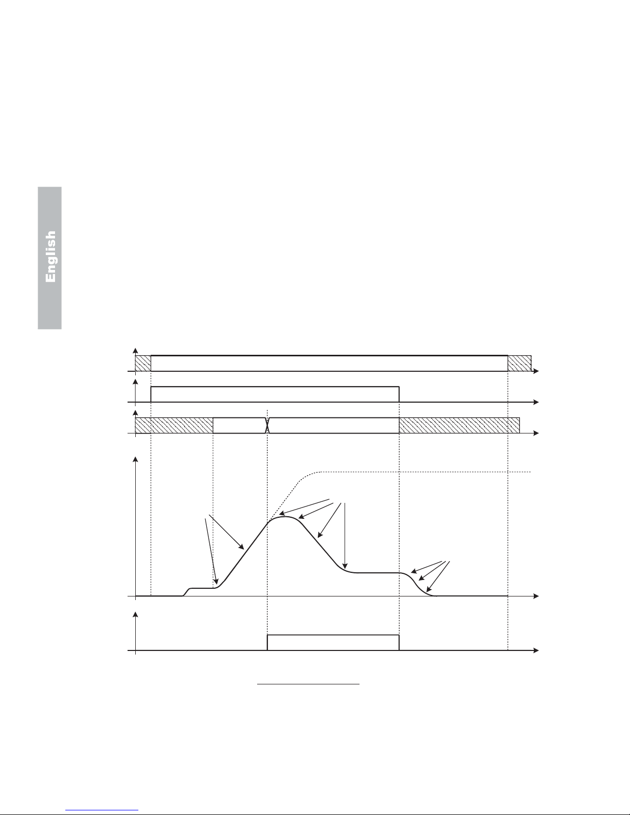
7.2 Lift Sequence
Timing diagrams of the lift sequence are reported in Fig. 7.2 and Fig. 7.3.
ЧтрррЫ²¿¾´»-®½
ЧтррпО«²Ъ©¼
-®½
ИСО
ЧтрроО«²О»ª
-®½
ЧтррнтттЧтррк
Ъ®»¯Н»´птттм
-®½
ïð
¼тррйС«¬°«¬
-°»»¼
øÓ±¬±®-°»»¼÷
¼трроС«¬°«¬
½«®®»²¬
шЧ²ª»®¬»®ч
ЕлпГЭ±²¬¿½¬±®
шцч
ÅìëÃ
øÓ±¬±®÷
Üݾ®¿µ·²¹
øö÷
ЕллГФ·º¬-¬¿®¬шцч
шцчжН»»йтотп
ï î í ì ë ê é
ЕлмГЮ®¿µ»½±²¬
шцч
Fig. 7.2 – Standard lift sequence
1.S.250 Cont close delay(Default : 0,20)
2.S.251Magnet time(Default : 1)
3.S.252Brake open delay(Default : 0,20)
4.S.253Smooth start dly(Default : 0)
5.S.254DCBrake stp time(Default : 1)
6.S.255Brake close dly(Default : 0,20)
7.S.256Cont open delay(Default : 0,20)
Note:
Lift sequence will not start if there is no current flowing on any of the motor windings during the initial
injection of DC-current. The minimum amount of current necessary to release the mechanical brake and
initiate the lift sequence is defined by A.087 Current pres thr. By setting the parameter to “0”, current check
is disabled, and the lift sequence will start even if the motor is disconnected from the drive.
Page 30

74 AGy -L
ïð
ß½½»´»®¿¬·±²
ë ê é
¿
¾
¾
¿
РтммрЪ®»¯М¸®п
НторпЪ®»¯О»ºпшЪтпрпч
НторрЪ®»¯О»ºршЪтпррч
Ü»½»´»®¿¬·±²øöö÷
Ö»®µ¼»½·²·øöö÷
Ö»®µ¼»½»²¼øöö÷
Ö»®µ¼»½»²¼øöö÷
Ö»®µ¼»½·²·øöö÷
Ü»½»´»®¿¬·±²øöö÷
ЧтрррЫ²¿¾´»-®½
ЧтррнтттЧтррк
Ъ®»¯Н»´птттм
-®½
ЕлпГЭ±²¬¿½¬±®
шцч
ЕмлГЬЭу¾®¿µ·²¹
øÓ±¬±®÷
øö÷
ЕллГФ·º¬-¬¿®¬шцч
шцчжН»»йтотп
шццчНтонртттНтомл
ЕлмГЮ®¿µ»½±²¬
шцч
ЧтррпО«²Ъ©¼
-®½
ИСО
ЧтрроО«²О»ª
-®½
¼тррйС«¬°«¬
-°»»¼
øÓ±¬±®-°»»¼÷
Fig. 7.3 – Detailed stopping sequence
a)S.260 Lift Stop Mode = [0] DC brake at stop(Default)
b)S.260 Lift Stop Mode = [1] Normal stop
7.2.1 Lift-dedicated digital output functions
Several specific functions can be programmed on the drive digital outputs, in order to check the correctness of the lift
sequence and to improve the interaction with the external sequencer. Here follows a list of the functions that can be useful
in lift applications.
DO Programming codeFunction description
[0] Drive readyTRUE when the drive is ready to accept a valid RUN command. Meaning that the drive is
not in alarm, the dc-link pre-charge is completed and the safe-start interlock logic is
cleared.
[1] Alarm stateTRUE when the drive is in alarm status. Alarm reset is needed to restore operation
[2] Not in alarmTRUE when the drive is not in Alarm status.
[3] Motor runTRUE when the inverter output bridge is enabled and operating.
[4] Motor stopTRUE when the inverter output bridge is not operating (all six switches are open).
[5] Rev rotationTRUE when the motor is rotating counter-clockwise.
[31] Freq > thr1TRUE when the motor speed (measured or estimated) is above the threshold defined by
parameters P.440 and P.441.
[32] Freq < thr1TRUE when the motor speed (measured or estimated) is below the threshold defined by
parameters P.440 and P.441. This function is normally used to detect zero speed (see
sequence in Fig.7.2). This signal is available as default on terminal 17, Digital output 2.
[45] DC brakingTRUE when DC injection is in progress.
[51] ContactorTRUE when the Run contactor has to be closed, either for upward or downward motion.
Page 31

AGy -L 75
This signal is available as default on terminal 16, Digital output 1.
[52] Contactor UPTRUE when the Run contactor for upward motion has to be closed.
[53] Contactor DOWNTRUE when the Run contactor for downward motion has to be closed.
[54] Brake contTRUE when the mechanical brake has to be released.
[55] Lift startTRUE when the inverter output bridge is operating and no DC injection is being operated.
7.2.2 Speed indication
At power-on the drive keypad shows the speed of the lift car (parameter d.007), expressed in mm/s. Likewise, all the
variables related to the speed of the motor (d.008, d.302) are expressed in mm/s. The conversion between electrical Hz
and car speed is automatically performed by the drive, as explained in the following chapter. The conversion ratio can also
be overwritten by the user, by setting parameter P.600.
The parameter to be shown at power-on can be configured by setting the parameter P.580.
7.3 Ramp Function
Four independent jerks are available for each profile, together with linear acceleration and deceleration times. All profile
parameters are expressed in terms of car linear quantities. The equivalence between car speed v(m/s) and inverter output
frequency f(Hz) is automatically performed by the drive, based on the value of the following parameters:
-f
b
:S.101 Base frequency (Hz)
-v
N
:S.180 Car max speed (m/s)
The ramp profile is shown in Fig.6. Profile number 1 has been used as an example, but the same applies to all the four
available profiles. The increase or decrease of the jerk values causes the increase or decrease of the running comfort.
Ó±¬±®-°»»¼
¼тррйС«¬°«¬-°»»¼
ß½½»´»®¿¬·±²
НтонрЦ»®µ¿½½·²·п
НтонпЯ½½»´»®¿¬·±²п
НтоноЦ»®µ¿½½»²¼п
НтоннЦ»®µ¼»½·²·пНтонлЦ»®µ¼»½»²¼п
НтонмЬ»½»´»®¿¬·±²п
Fig.7.4 – Lift ramp profile
7.3.1 Space calculation and acceleration / deceleration ramps settings
The space covered by the lift car during acceleration and deceleration ramps can be calculated off-line by the drive, by
executing the command: C.060 Calculate space . The results of the calculation can be monitored into the parameters:
d.500 Lift space space covered by the lift car (expressed in meters) when accelerating from zero to the
maximum speed (defined by S.180) and then immediately decelerating back to zero(one
floor travel)
d.501 Lift accel space space covered by the lift car (expressed in meters) when accelerating from zero to the
maximum speed (defined by S.180).
d.502 Lift decel space pace covered by the lift car (expressed in meters) when decelerating from the maximum
speed (defined by S.180) to zero.
Knowing the space needed to accelerate and decelerate the lift car with the ramp set in use, is useful to determine whether
the ramps are compatible with the position of the floor sensors before actually starting the drive. For example, if the
Page 32
76 AGy -L
deceleration ramp is too slow, as compared to the re-aligning distance, the lift car could stop after the floor level.
If acceleration and/or deceleration ramps are too fast, the drive may reach the output current limit. In this case, the drive
will automatically clamp the current to a safe value, with a resulting loss of output torque. If the drive remains in limit
condition for the time specified by the parameter P.181 - Clamp alm HldOff (default setting is 1 second), an alarm will be
issued ("LF - Limiter fault") and the lift sequence will be aborted. It is strongly recommended not to operate the drive in
current limit, since the desired speed profile cannot be achieved in that case, resulting in undesired oscillations. If the drive
reaches the current limit during the acceleration or deceleration phases, it is advised to slow down the ramps, until the limit
condition is avoided.
7.3.2 Short Floor Function
Sometimes, the space between adjacent floors is not constant, and there is one floor that may be nearer to the next one.
That situation is normally referred as “Short Floor”. It could happen that due to the reduced distance, the lift is required to
decelerate to the leveling speed, when the acceleration ramp to normal speed is still in progress. This will lengthen the
approaching phase, unless countermeasures are taken.
The drive is able to detect a Short Floor, by looking at the sequence.
The flag "ShortFloorFl" is set if the deceleration command is given during the acceleration phase.
I.007 Ramp sel 1 src = “[25] ShortFloorFl”
The flag is reset when the stop command is given, or when the sequence is aborted.
"ShortFloorFl" is default used to control the short floor, using the second set of ramps.
The regulation of the parameters from S.240to S. 245 allows to define the area to be covered before reaching the floor. In
case of short floor, if the lift overcomes the floor it means that the lift speed was too high and it is therefore necessary to
increase the jerk values (parameters S.242, S.243, S.244). If the plant works for a too long time with a low speed before
reaching the floor, the jerk values have to be decreased (parameters S.242, S.243, S.244).
A typical short floor sequence is reported in Fig. 7.5 .
ïð
Ø·¹¸-°»»¼-»¬°±·²¬
Ô»ª»´·²¹-°»»¼
ͳ±±¬¸-¬¿®¬-°»»¼
ο³°-»¬ï
ο³°-»¬î
ο³°-»¬ï
ЧтрррЫ²¿¾´»-®½
ЧтррпО«²Ъ©¼-®½
ИСО
ЧтрроО«²О»ª-®½
ЧтррнтттЧтррк
Ъ®»¯Н»´птттм-®½
¼тррйС«¬°«¬-°»»¼
øÓ±¬±®-°»»¼÷
ЧтррйО¿³°-»´п-®½г
ЕолГН¸±®¬º´±±®Ъ´
Fig. 7.5 – Short floor sequence
Ramp references:1S.240 Jerk acc ini 2 4 S.243Jerk dec ini 2
2 S.241Acceleration 2 5 S.244Deceleration 2
3 S.242Jerk acc end 2 6 S.245Jerk dec end 2
Page 33

AGy -L 77
7.4 Startup Menu
Lift version has parameters that are organized with access levels, as follows:
ß½½»--´»ª»´ß½½»--·¾´»°¿®¿³»¬»®-
óÞ¿-·½¼·-°´¿§ °¿®¿³»¬»®уЭ±³³¿²¼º±®-¿ª»°¿®¿³»¬»®уРтззи
уЯ´´´»ª»´п°¿®¿³»¬»®уН¬¿®¬«°°¿®¿³»¬»®уЯ´´½±³³¿²¼-
íß´´°¿®¿³»¬»®-
¬¿¾ðëðó¹
ï
îøÜ»º¿«´¬÷
The access level is set by the parameter P.998 Param access lev.
Note!.
When using E@syDrives configurator, all parameters are accessible, regardless of what is specified by
parameter P.998.
In order to make drive installation easy, all the parameters needed for standard setup are gathered in the STARTUP menu.
This menu consists of links to parameters present in different drive menus. Therefore, making a change to any of the
parameters in Startup, is equivalent to make the same change to the linked parameter in another menu.
The list of parameters in Startup menu of the lift version follows:
Note!
(*) = Size dependent
(ALIAS): On STARTUP menu only.Parameter code of same parameter on other menu .
Menu S - Startup
CodeDisplay (Description) Def.Min.Max
S.000Mains voltage (linked to P.020) 380230480
Nominal voltage (Vrms) of the AC input mains.
S.001Mains frequency (linked to P.021) 5050 60
Nominal frequency (Hz) of the AC input mains.
S.100Base voltage (linked to P.061) 38050 528
Maximum inverter output voltage (Vrms). It should be set to motor rated voltage, as shown on the nameplate.
S.101Base frequency (linked to P.062) 5025 500
Motor base frequency (Hz). It is the frequency at which the output voltage reaches the motor rated (data on motor nameplate).
S.150Motor rated curr (linked to P.040) (*)(*) (*)
Motor rated current (Arms). It should be set according to motor nameplate.
S.151Motor pole pairs (linked to P.041) 21 60
Number of pole pairs of the motor (data on motor nameplate).
S.152Motor power fact (linked to P.042) (*)(*) (*)
Motor input power factor at rated current and rated voltage. It should be set according to nameplate.
S.153Motor stator R (linked to P.043) (*)(*) (*)
Equivalent resistance of the motor stator windings (Ohm). This value is important for correct operation of the automatic boost, and
slip compensation functions. It should be set to half of the resistance measured between two of the motor input terminals, with the
third terminal open. If unknown, it can be automatically measured by the autotuning command (see S.170).
S.170Measure stator R (linked to C.100) 0.500.015.00
The execution of this command allows the user to measure the equivalent stator resistance of the motor in use. After the
command is issued, it is necessary to initiate a standard run sequence, by giving enable and start commands. The inverter
will close the run contactor, but will not release the brake, allowing for current to flow in the windings. After the procedure is
successfully completed, the value of S.153 is automatically updated.
Page 34

78 AGy -L
S.180Car max speed (linked to A.090) 0.500.01 5.00
Speed of the lift car (m/s) when the inverter outputs the rated frequency.
S.200 Frequency ref 0 (linked to F.100) 10.0-F.020 F.020
See description of S.207.
S.201 Frequency ref 1 (linked to F.101) 50.0-F.020 F.020
See description of S.207.
S.202 Frequency ref 2 (linked to F.102)
S.203 Frequency ref 3 (linked to F.103)
S.204 Frequency ref 4 (linked to F.104)
S.205 Frequency ref 5 (linked to F.105)
S.206 Frequency ref 6 (linked to F.106)
S.207 Frequency ref 7 (linked to F.107) 0.0-F.020 F.020
Frequency references (Hz) of the inverter. The selection of any of the above references is performed by the dedicated
selectors (Freq Sel 0 to 4). Although only 8 references are present in the startup menu, it is possible to use up to 16 different
references, available in the menu F.
S.220 Smooth start frq (linked to F.116) 2.0-F.020 F.020
Frequency reference (Hz) used during the smooth start procedure.
S.225 Ramp factor 1 (linked to A.091) 1.000.01 2.50
Ramp accel/decel and jerks are defined by the parameters described below. However, for an easy setting, it is possible to
use a common extension factor to speed-up or slow down the ramps. For example, if S.225 is set to 0.5, all the parameters
related to the sets 1 and 3 of ramps (accels, decels and jerks) are halved, resulting in slower ramps.
S.226 Ramp factor 2 (linked to A.092) 1.000.012.50
Same as S.225, but it applies to the ramp sets 2 and 4.
S.230 Jerk acc ini 1 (linked to F.251) 0.500.01 10.00
Jerk (m/s3) applied at the beginning of an acceleration with ramp set 1 (Ramp set 1 is the one used by default, during normal
operation).
S.231 Acceleration 1 (linked to F.201) 0.600.01 5.00
Linear acceleration (m/s2) with ramp set 1.
S.232Jerk acc end 1 (linked to F.252) 1.40 0.01 10.00
Jerk (m/s3) applied at the end of an acceleration with ramp set 1.
S.233 Jerk dec ini 1 (linked to F.253) 1.400.01 10.00
Jerk (m/s3) applied at the beginning of a deceleration with ramp set 1.
S.234 Deceleration 1 (linked to F.202) 0.600.01 5.00
Linear deceleration (m/s2) with ramp set 1.
S.235Jerk dec end 1 (linked to F.254) 1.000.01 10.00
Jerk (m/s3) applied at the beginning of a deceleration with ramp set 1.
S.240 Jerk acc ini 2 (linked to F.255) 0.500.01 10.00
Jerk (m/s3) applied at the beginning of an acceleration with ramp set 2 (Ramp set 2 is the one used by default when a short
floor is detected).
CodeDisplay (Description) Def.Min.Max
Page 35

AGy -L 79
S.241Acceleration 2 (linked to F.203) 0.600.01 5.00
Linear acceleration (m/s2) with ramp set 2.
S.242Jerk acc end 2 (linked to F.256) 1.400.01 10.00
Jerk (m/s3) applied at the beginning of a deceleration with ramp set 2.
S.243Jerk dec ini 2 (linked to F.257) 1.400.01 10.00
Jerk (m/s3) applied at the beginning of a deceleration with ramp set 2.
S.244Deceleration 2 (linked to F.204) 0.600.01 5.00
Linear deceleration (m/s2) with ramp set 2.
S.245Jerk dec end 2 (linked to F.258) 1.000.01 10.00
Jerk (m/s3) applied at the beginning of a deceleration with ramp set 2.
S.250Cont close delay (linked to A.080) 0.200.00 10.00
Delay time (s) for safe closing or the run contactor.
S.251Magnet time (linked to A.081) 1.000.00 10.00
Duration (s) of the initial magnetization of the motor with DC injection.
S.252Brake open delay (linked to A.082) 0.200.00 10.00
Delay time (s) between the open command and effective opening of the mechanical brake.
S.253Smooth start dly (linked to A.083) 0.000.00 10.00
Duration (s) of the smooth start phase.
S.254DCBrake stp time (linked to A.084) 1.000.00 10.00
Duration (s) of the stopping phase, after the speed has fallen below the zero threshold (defined by parameter P.440). During
this phase, the inverter can either output a DC current, or maintain a low frequency, in order to compensate for the slip
(default), as programmed by S.260.
S.255Brake close dly (linked to A.085) 0.200.00 10.00
Delay time (s) between the close command and the effective engagement of the mechanical brake.
S.256Cont open delay (linked to A.086) 0.200.00 10.00
Delay time (s) between the open command and the affective opening of the run contactor.
S.260Lift stop mode (linked to A.220) [1] Normal stop
After the car speed falls below the zero threshold (defined by P.440), the inverter can be programmed to brake with DC
injection (S.260 = 0), or to maintain a low frequency output in order to compensate for the estimated slip (S.260 = 1). The
latter is set by default.
Possible selections:[0] DC brake at stop
[1] Normal stop
S.300Manual boost [%] (linked to P.120) 3.00.0 25.0
Voltage boost (% of motor rated voltage) applied at low frequency in order to maintain the machine flux.
S.301Auto boost en (linked to P.122) [0] Disable
The automatic boost allows for precise compensation of the resistive voltage drop due to the winding resistance, keeping the
flux at its rated value regardless of the load level and output frequency. For correct operation of this function, a precise value
of the equivalent stator resistance is needed.
Possible selections:[0] Disable
[1] Enable
S.310Slip compensat (linked to P.100) 500 250
Amount of slip compensation (% of rated slip, calculated from nameplates) during motoring (power flows from motor to load).
S.311Slip comp regen (linked to P.102) 500 250
CodeDisplay (Description) Def.Min.Max
Page 36

80 AGy -L
Amount of slip compensation (% of rated slip, calculated from nameplates) during regeneration (power flows back from load
to motor).
S.312 Slip comp filter (linked to P.101) 0.30.0 10.0
Time constant (s) of the filter used for slip compensation. The lower this value, the faster the compensation, with improved
speed control. Excessively fast slip compensation may cause unwanted oscillations.
S.320DC braking level (linked to P.300) 750 100
Amount of current (% of drive rated current) injected during magnetization and stopping phases.
S.400 Control mode (linked to P.010) [0] V/f OpenLoop
Set this parameter to “[0] Open loop V/f” when there is no encoder feedback available.
Set to “[1] Closed loop V/f” otherwise.
Possible selections:[0] V/f OpenLoop
[1] V/f ClsdLoop
S.401 Encoder ppr (linked to I.501) 10241 9999
Resolution of the encoder in use, expressed in number of pulses per mechanical revolution (ppr). It is a nameplate data of the
encoder.
S.450Spd ctrl P-gainH (linked to P.172) 2.00.0100.0
Proportional gain of speed PI regulator.
S.451Spd ctrl I-gainH (linked to P.173) 1.00.0 100.0
Integral gain of speed PI regulator.
S.452Spd PI High lim (linked to P.176) 10.00.0 100.0
Maximum allowed output of the speed PI regulator (% of maximum frequency, F.020). It represents the maximum amount of
slip that is allowed during motoring operation.
S.453Spd PI Low lim (linked to P.177) -10.0-100.00.0
Minimum allowed output of the speed PI regulator (% of maximum frequency, F.020). It represents the maximum amount of
slip (negative) that is allowed during braking operation.
Note!
It is possible to configure gain scheduling for the speed PI regulator.
S.901 Save parameters (linked to C.000)
The execution of this command will save all the parameters into the permanent memory of the drive. All unsaved settings will
be lost if the power is cycled.
CodeDisplay (Description) Def.Min.Max
Page 37

AGy -L 81
7.5 Menù Display
d.000Output frequency Drive output frequency Hz0.01001
d.001Frequency ref Drive frequency reference Hz0.01002
d.002Output current Drive output current (rms) A0.1003
d.003Output voltage Drive output voltage (rms) V1004
d.004DC link voltage DC Bus drive voltage (DC) V1005
d.005Power factor Power factor 0.01006
d.006Power [kW] Inverter output power kW0.01007
d.007Output speed Drive output speed mm/s1008
d.008Speed ref Drive speed reference (d.001)*(P.600) mm/s1009
d.050Heatsink temp Drive heatsink temperature (linear sensor measured) °C1010
d.051Drive OL Drive overload (100% = alarm threshold) %0.1011
d.052Motor OL Motor overload (100% = alarm threshold) %0.1012
d.053Brake res OL Braking resistor overload (100%=alarm thr) %0.1013
d.100Dig inp status Digital inputs status acquired by the drive (terminal or virtual) 014
d.101Term inp status Digital inputs terminal status of the drive regulat. Board 015
d.102Vir dig inp stat Virtual digital inputs status from drive serial link or field bus card 016
d.120Exp dig inp stat Expansion digital inputs status (optional terminal or virtual) 017
d.121Exp term inp Expansion digital inputs terminal status of the drive expansion board 018
d.122Vir exp dig inp Expansion virtual digital inputs status from drive serial link or field bus card 019
d.150Dig out status Digital outputs status on the terminals of the drive regulation board 020
(commanded by DO functions or virtual DO)
d.151Drv dig out sta Digital outputs status, commanded by DO functions 021
d.152Vir dig out sta Virtual digital outputs status, commanded via serial link or field bus card
022
d.170Exp dig out sta Expansion digital outputs status on the terminals of the drive regulation board 023
(commanded by DO functions or virtual DO)
d.171Exp DrvDigOutSta Expansion digital outputs status, commanded by DO functions 024
d.172Exp VirDigOutSta Expansion virtual digital outputs status 025
(commanded via serial link or field bus card)
d.200An in 1 cnf mon Analog input 1 destination; 026
it shows the function associated to this analog input
[0] Null funct
[1] Rif freq 1
[2] Rif freq 2
[3] Fatt liv Bst
[4] Fatt liv OT
[5] FattLiv Vred
[6] Fatt liv DCB
[7] FattEst Ramp
[8] FattRif freq
[9] VelPI LimFac
[10] MltFrq ch 1
[11] MltFrq ch 2
CodeDisplayDescription UnitVar.IPA
Page 38

82 AGy -L
d.201An in 1 monitor Analog input 1 output block % value 027
d.202An in 1 term mon Analog input 1 input block % value 028
d.210An in 2 cnf mon Analog input 2 destination; 029
it shows the function associated to this AI. As per d.200
d.211An in 2 monitor Analog input 2 output block % value 030
d.212An in 2 term mon Analog input 2 input block % value 031
d.220An in 3 cnf mon Analog input 3 destination; 032
it shows the function associated to this AI. As per d.200
d.221An in 3 monitor Analog input 3 output block % value 033
d.222An in 3 term mon Analog input 3 input block % value 034
d.250LCW To PLC (0-7) Monitor of the control bits sent to the internal sequencer. Bit 0 to 7 66
d.251LCW To PLC(8-15) Monitor of the control bits sent to the internal sequencer. Bit 8 to 15 67
d.252LCW Fr PLC (0-7) Monitor of the control bits generated by the internal sequencer. Bit 0 to 7 68
d.253LCW Fr PLC(8-15) Monitor of the control bits generated by the internal sequencer. Bit 8 to 15 69
d.254LCW FrPLC(16-23) Monitor of the control bits generated by the internal sequencer. Bit 16 to 23 70
d.255LSW (0-7) Monitor of the drive status. Bit 0 to 7. 71
d.300EncPulses/Sample Number of encoder pulses, 1/100035
recorded in the time interval defined by parameter I.504.
d.301Encoder freq Encoder frequency reading (Motor frequency) Hz0.01036
d.302Encoder speed Encoder speed reading (d.000)*(P.600) 0.01/1037
d.350Option 1 state Drive option 1 state 038
d.351Option 2 state Drive option 2 state 039
d.353Sbi state Communication state between SBI and Master 059
0Wait parametrization
1Wait configuration
2Data exchange
3Error
d.354Sbi baudrate Communication speed between SBI and Master 060
012 Mbit / s
16 Mbit / s
23 Mbit / s
31.5 Mbit / s
4500 Kbit / s
5187.5 Kbit / s
693.75 Kbit / s
745.45 Kbit / s
819.2 Kbit / s
15unknown
d.400PID reference PID reference signal %0.1041
d.401PID feedback PID feedback signal %0.1042
d.402PID error PID error signal %0.1043
d.403PID integr comp PID integral component %0.1044
d.404PID output PID output signal %0.1045
CodeDisplayDescription UnitVar.IPA
Page 39

AGy -L 83
d.450Mdplc error Status of internal sequencer 62
0No error
1Internal sequencer error
d.500Lift space m0.0163
Space needed to accelerate the car from zero to max speed and then decelerate back to zero
d.501Lift space
Space needed to accelerate the car from zero to max speed
d.502Lift space m0.0165
Space needed to decelerate the car from max speed to zero
d.8001st alarm-latest Last alarm stored by the drive alarm list 046
See par. 10.3
d.8012nd alarm Second to last alarm 047
d.8023rd alarm Third to last alarm 048
d.8034th alarm Fourth to last alarm 049
d.950Drive rated curr Drive rated current (it depends on the drive size) 0.1050
d.951SW version (1/2) Software version - part 1 (03.01) 0.01051
d.952SW version (2/2) Software version - part 2 (00.00) 0.01052
d.957Drive size Drive size code 057
44kW - 230/400/460V
55.5kW - 230/400/460V
67.5kW - 230/400/460V
711kW - 230/400/460V
815kW - 230/400/460V
922kW - 230/400/460V
1030kW - 230/400/460V
1137kW - 230/400/460V
1245kW - 230/400/460V
1355kW - 230/400/460V
1475kW - 230/400/460V
1590kW - 230/400/460V
16110kW - 230/400/460V
17132kW - 230/400/460V
18160kW - 230/400/460V
2118.5kW - 230/400/460V
25200kW - 230/400/460V
d.958Drive cfg type Drive configuration type 061
[0]Standard: 400Vac, 50Hz
[1] American: 460Vac, 60Hz
d.999Display Test Drive display test
CodeDisplayDescription UnitVar.IPA
Page 40

84 AGy -L
8 - Encoder Interface (EXP-ENC-AGy option board)
AGy -L provides an enhanced encoder interface for closed loop speed control.
Standard two channels quadrature digital encoders with 5V, 8V or 24V power supply can be used. Maximum input frequency
on either channel is 150kHz.
8.1 Wiring
The EXP-ENC-AGy expansion card allows the connection of a digital encoder TTL (+5V) or HTL (+24V).
Default setting= HTL (+24V)
24V Encoder mains supply When an HTL encoder is used, on terminals 9 and 10 of R-AGy-2 regulation card
is available the following voltage:
- terminal 9 : +24V OUT
- terminal 10 : 0V24 - GND
8V, 5V Encoder mains supply This DC supply is available on terminals 35 and 36 of EXP-ENCAGy card :
Term. DesignationFunction
12A+ A channel positive
13A- A channel negative
14B+ B channel positive
15B- B channel negative
35Vcc 8V , 5V (*) Vcc Encoder mains supply
38GND GND Encoder mains supply
(*)selectable via software by I.505 parameter, into INTERFACE menu.
8.2 Setting of encoder power supply
24V HTL encoders can be supplied by using the +24V output, available on the standard regulation board (terminal 9); in
that case terminals 35 and 36 on EXP-ENC-AGy card should be left unconnected.
The two jumpers S1 on the EXP-ENC-AGy board must be OFF (default), meaning that A and B channels are HTL.
TTL encoders, requiring 5V or 8V power supply can be supplied by using terminals 35 and 36 of EXP-ENC-AGy.
The voltage level output on those terminals is determined by the drive parameter: I.505 Enc power supply.
Allowed settings are:
[0]5.2V
[1]5.6V
[2]8.3V
[3]8.7V
Proper setting is determined according to encoder specifications and cable length. The longer is the cable connecting the
external power supply to the encoder, the higher should be the setting.
Select the two jumpers S1, on the EXP-ENC-AGy board, to ON, meaning that A and B channels are TTL.
Refer to Fig.7.1 for a sample wiring diagram.
8.3 Encoder sign test
Before to use closed loop speed control it is necessary to verify if sign of acquired encoder speed corresponds to reference
speed. For this:
1 -run the drive in open loop mode and set S.400 Control mode = [0] V/f OpenLoop; I.500 Encoder enable = [1]
Enable)
2 -on Display menu select d.001 Rif frequenza andd.301 Freq. encoder parameters and compare the signs .
3 -in case of different signs please invert connection of encoder channels A+ , A- with B+, B-
Page 41

AGy -L 85
8.4 Encoder cable break control function
The encoder cable break control function is available from card EXP-ENC-AGy rev. C with fw 3.04 and later.
To enable the function, set parameter I.506 Enc fault enable = 1 (Enabled)
Note!
For instructions on how to connect single-channel encoders and enable the encoder cable break control
function and for details of electrical specifications and configurations, please see the manual supplied with the
EXP-ENC-AGy card.
Page 42

86 AGy -L
9 - Emergency Operation
AGy -L is able to operate from a backup power supply (batteries, or single-phase 220Vac) in case of mains fault.
In figure 7.1, typical connection diagram of the Emergency Module MW22 is shown. When using this configuration, the
following parameters have to be changed from default, in order to activate the emergency operation:
- I.005 Freq Sel 3 src = “[0] False”
- I.011 Bak pwr act src = “[7] DI 6”
When the drive detects an Under Voltage condition (either because of a mains fault or because the drive has been
powered up from backup module), if the “Bak Pwr Active” command is active (contactor KB closed), the UV Alarm is
automatically reset and the drive will enter the Emergency Mode.
While in Emergency mode, the drive is able to operate with a low DC-link voltage (supplied from the emergency module).
Operation is exactly the same as in normal mode (Run command and frequency reference are issued as usual), but the
inverter output frequency is clamped by the internal logic to the value specified in parameter F.115 BakPwr max freq.
Note!
While in Emergency Mode, the AC-mains contactor must be open.
If the AC-mains contactor is closed and the power is restored while the drive is still in Emergency Mode, the
input bridge of the inverter may fail due to inrush current of DC-link capacitors.
Once the emergency operation is completed, the drive should be turned off, by opening contactor KB, in order not to
discharge the batteries. When the drive is turned off, the AC mains contactor K1M can be closed, so that the drive is ready
to operate when the power is restored.
Page 43

AGy -L 87
10 - Troubleshooting
10.1 Drive Alarm Condition
The drive keypad will show on the 2nd line of alphanumeric display a blinking message with the code and name of the
alarm occurred.
The figure below shows an example of OV Overvoltage alarm condition during d.000 Output frequency parameter
displaying.
ئ ß ÊЮ¹ λª Ú©¼
Ю¹
Ñ«¬°«¬º®»¯«»²½§
ðÊѪ»®ª±´¬¿¹»
ß´¿®³³»--¿¹»¾´·²µ·²¹
ئ ß ÊЮ¹ λª Ú©¼
Ю¹
ðË
ß´¿®³½±¼»¾´·²µ·²¹
λ¼ÔÛܾ´·²µ·²¹
λ¼ÔÛܾ´·²µ·²¹
ХЮЩупш-¬¿²¼¿®¼чХЮЩуФЭЬуттшС°¬·±²¿´ч
Figure 10.1.1: Alarm Displaying for LDC and 7 segments display
The active alarm can be acknowledged by pressing the Prg button on the keypad.
This operation will allow menu navigation and parameter editing while the drive is in alarm state (red LEDs blinking).
In order to resume drive operation, an Alarm reset command is necessary.
10.2 Alarm Reset
Alarm reset can be performed in three different ways:
- Alarm reset by keypad: pressing simultaneously Up and Down keys; the reset
action will take effect when the buttons are released.
- Alarm reset by digital input: it can be performed through a programmable digital input
connected to command I.010 Fault reset src = [9]
Digital input 8 (terminal 4).
. Alarm reset by Autoreset function: it allows an automatic reset of some drive alarms (see
table 10.3.1), by the settings of P.380, P.381, P.382 and
P.383 parameters.
The figure below shows how to reset an alarm by keypad.
Ñ«¬°«¬º®»¯«»²½§
ðÊѪ»®ª±´¬¿¹»
Ñ«¬°«¬º®»¯«»²½§
ртррШ¦
ß´¿®³½±²¼·¬·±²ß´¿®³®»-»¬¬»¼
Þ´·²µ·²¹
ß´¿®³½±²¼·¬·±²ß´¿®³®»-»¬¬»¼
Þ´·²µ·²¹
ХЮЩупш-¬¿²¼¿®¼ч
ХЮЩуФЭЬуттшС°¬·±²¿´ч
Figure 10.2.1: Alarm Reset
Page 44

88 AGy -L
10.3 List of drive alarm events
Table 10.3.1 provides a description of the causes for all the possible alarms.
ݱ¼òÒ¿³»
ЫЪЫЪЫ¨¬Ъ¿«´¬
׬¬®·°-©¸»²Û¨¬»®²¿´º¿«´¬·²°«¬·-¿½¬·ª»ï
ÇÛÍ
ð
СЭСЭСª»®Э«®®»²¬
׬¬®·°-©¸»²¿²Ñª»®½«®®»²¬ª¿´«»·-¼»¬»½¬»¼¾§±«¬°«¬½«®®»²¬-»²-±®î
ÇÛÍ
ï
СЛСКСª»®К±´¬¿¹»
׬¬®·°-©¸»²¬¸»¼®·ª»ÜÝÞ«-ª±´¬¿¹»·-¸·¹¸»®¬¸¿²¬¸»³¿¨·³«²¬¸®»-¸±´¼º±®
¬¸»¹·ª»²³¿·²ª±´¬¿¹»-»¬¬·²¹
í
ÇÛÍ
î
ЛЛЛКЛ²¼»®К±´¬¿¹»
׬¬®·°-©¸»²¬¸»¼®·ª»ÜÝÞ«-ª±´¬¿¹»·-´±©»®¬¸¿²¬¸»³¿¨·³«²¬¸®»-¸±´¼º±®
¬¸»¹·ª»²³¿·²ª±´¬¿¹»-»¬¬·²¹
ì
ÇÛÍ
í
СШСШСª»®М»³°»®¿¬
׬¬®·°-©¸»²¬¸»¼®·ª»¸»¿¬-·²µ¬»³°»®¿¬«®»¼»¬»½¬»¼¾§¬¸»-©·¬½¸-»²-±®
»¨½»»¼-·¬-¬¸®»-¸±´¼øö÷
ë
ÒÑ
ì
ÑÔ·ÑÔ·Ü®·ª»ÑÔ
׬¬®·°-©¸»²¬¸»¼®·ª»±ª»®´±¿¼¿½½«³«´¿¬±®»¨½»»¼»¼¬¸»¬®·°¬¸®»-¸±´¼êÒÑë
СФУСФУУ±¬±®СФ ×¬¬®·°-©¸»²¬¸»³±¬±®±ª»®´±¿¼¿½½«³«´¿¬±®»¨½»»¼»¼¬¸»¬®·°¬¸®»-¸±´¼é
ÒÑ
ê
ÑÔ®ÑÔ®Þ®¿µ»®»-ÑÔ
׬-·²¬»®ª»²¬·±²±½½«®-©¸»²¬¸»±ª»®´±¿¼½§½´»±º¬¸»»¨¬»®²¿´¾®¿µ·²¹
®»-·-¬¿²½»¼±»-²±¬½±®®»-°±²¼¬±¬¸»¼»º·²»¼´·³·¬-ò
è
ÒÑ
é
ѬѬײ-¬Ñª»®Ì®¯
׬¬®·°-©¸»²¬¸»¬±®¯«»¼»´·ª»®»¼¾§¬¸»³±¬±®»¨½»»¼-¬¸»°®±¹®¿³³»¼´»ª»´
º±®¬¸»°®»-»¬¬·³»
ç
ÒÑ
è
РШРШР¸¿-»´±--
׬¬®·°-©¸»²¬¸»-«°°´§°¸¿-»´¿½µæ»²¿¾´»¼íð-»½±²¼-¿º¬»®±²»±º¬¸»-«°°´§
°¸¿-»-¸¿-¾»»²¼·-½±²²»½¬»¼
ïð
ÒÑ
ç
ЪЛЪЛЪ«-»Ю´±©²
׬¬®·°-©¸»²¬¸»¼®·ª»·²°«¬º«-»-¿®»¾´±©²ïï
ÒÑ
ïð
СЭШСЭШЬ»-¿¬Я´¿®³ ×ÙÞ̼»-¿¬«®¿¬·±²±®·²-¬¿²¬¿²»±«-±ª»®½«®®»²¬¸¿ª»¾»»²¼»¬»½¬»¼ïî
ÇÛÍ
ïï
ͬͬͻ®·¿´ÌÑ
Ч¬¬®·°-©¸»²¬¸»-»®·¿´´·²µ¬·³»±«¬»¨½»»¼-¬¸»°®±¹®¿³³»¼´»ª»´шЧткрм
°¿®¿³»¬»®ч
ïí
ÇÛÍ
ïî
СРпСРпС°¬пЯ´³
ݱ³³«²·½¿¬·±²º¿·´«®»¾»¬©»»²¼®·ª»®»¹«´¿¬·±²¾±¿®¼¿²¼±°¬·±²ï»¨°¿²-·±²
¾±¿®¼
ïì
ÒÑ
ïí
СРоСРоС°¬оЯ´³
ݱ³³«²·½¿¬·±²º¿·´«®»¾»¬©»»²¼®·ª»®»¹«´¿¬·±²¾±¿®¼¿²¼±°¬·±²î»¨°¿²-·±²
¾±¿®¼
ïë
ÒÑ
ïì
¾Ú¾ÚÞ«-Ú¿«´¬
Ü®·ª»½±³«²·½¿¬·±²Þ«-º¿·´«®»ïê
ÒÑ
ïë
СШНСШНСª»®М»³°»®¿¬
Ч¬¬®·°-©¸»²¬¸»¼®·ª»¸»¿¬-·²µ¬»³°»®¿¬«®»»¨½»»¼-¿-¿º»¬§´»ª»´тшцчпй
ÒÑ
ïê
НШЭНШЭН¸±®¬Э·®½
͸±®¬Ý·®½«·¬¾»¬©»»²±«¬°«¬°¸¿-»-±®Ù®±«²¼º¿«´¬ïè
ÒÑ
ïé
Ѹ®
λ-»®ª»¼ ïçïè
ÔºÔÚÔ·³·¬»®º¿«´¬
׬¬®·°-©¸»²¬¸»±«¬°«¬½«®®»²¬´·³·¬»®±®¬¸»ÜÝóÔ·²µª±´¬¿¹»´·³·¬»®º¿·´ò̸»
º¿·´«®»½¿²¾»½¿«-»¼¾§©®±²¹-»¬¬·²¹-±º®»¹«´¿¬±®¹¿·²-±®¾§¬¸»³±¬±®´±¿¼ò
îð
ÒÑ
ïç
РФЭРФЭР´½º¿«´¬
РФЭ°®±¹®¿³²±¬¿½¬·ª»тФ·º¬¿°°´·½¿¬·±²¼±»-²±¬º«²½¬·±²т
О«²Этрлр°¿®¿³»¬»®¬±®»-»¬¬¸»¿´¿®³т
îï
ÒÑ
îð
ÛÓÍÕ»§Û³Í¬°º¿«´¬
λ-»®ª»¼ îî
ÒÑ
îï
ЛШНЛШНЛ²¼»®М»³°»®¿¬
׬¬®·°-©¸»²¬¸»¬»³°»®¿¬«®»±º¬¸»¼®·ª»¸»¿¬-·²µ·-¾»´±©¿-¿º»¬§´»ª»´
ø¬§°·½¿´´§ŠëpÝ÷ò
îí
ÒÑ
îî
ÛÒÝÛ²½±¼»®º¿«´¬
׬¬®·°-·²½¿-»±º¿°±©»®´±--±²¬¸»½¿¾´»½±²²»½¬·²¹¬¸»»²½±¼»®¬±¬¸»
¼®·ª»ò
îì
ÒÑ
îí
ÐØÑи¿-»Ô±--Ñ«¬°«¬
Н»»º·¹«®»йтож·¬¬®·°-¼«®·²¹¬¸»°¸¿-»шоч·º¬¸»½«®®»²¬¼±»-²±¬»¨½»»¼¬¸»
´·³·¬¼»º·²»¼·²°¿®¿³»¬»®Ятрийт
îë
ÒÑ
îì
ЯФЯОУ
ЬЫНЭОЧРМЧСТ
*) OH switch sensor threshold and OHS analog sensor threshold depend on the drive size (75 °C ... 85 °C)
Table 10.3.1 Alarm event list
Page 45

AGy -L 89
11 - EMC Directive
EMC Directive
The possible Validity Fields of the EMC Directive (89/336) applied to PDS
“CE marking” summarises the presumption of compliance with the
Essential Requirements of the EMC Directive, which is formulated in the EC Declaration of Conformity
Clauses numbers [.] refer to European Commission document “Guide to the Application of Directive 89/336/EEC”
1997 edition. ISBN 92-828-0762-2
Validity Field
-1-
Finished Product/
Complex component
available to general public
[Clauses: 3.7, 6.2.1, 6.2.3.1 &
6.3.1]
A PDS (or CDM/BDM) of the
Unrestricted Distribution class
-2-
Finished Product/
Complex component
only for professional assemblers
[Clauses: 3.7, 6.2.1, 6.2.3.2 &
6.3.2]
A PDS (or CDM/BDM)
of the Restricted Distribution class
sold to be included as part of a
system or installation
-3-
Installation
[Clause: 6.5]
Several combined items of system,
finished product or other components
brought together at a given place.
May include PDSs (CDM or BDM),
possibly of different classes -
Restricted or Unrestricted
-4-
System
[Clause: 6.4]
Ready to use finished item(s). May
include PDSs (CDM or BDM),
possibly of different classes
- Restricted or Unrestricted
Description
Placed on the market as a single commercial unit for distribution and final use.
Free movement based on compliance with the EMC Directive
- EC Declaration of conformity required - CE marking required
- PDS or CDM/BDM should comply with IEC 1800-3/EN 61800-3
The manufacturer of the PDS (or CDM/BDM) is responsible for the EMC behaviour of the PDS (or
CDM/BDM), under specified conditions. EMC measures outside the item are described in an easy
to understand fashion and could actually be implemented by a layman in the field of EMC.
The EMC responsiblity of the assembler of the final product is to follow the manufacturer’s
recommendations and guidelines.
NOTE: The manufacturer of the PDS (or CDM/BDM) is not responsible for the resulting behaviour
of any system or installation which includes the PDS, see Validity Fields 3 or 4.
Not placed on the marked as a single commercial unit for distribution and final use.
Intended only for professional assemblers who have a level of technical competence to correctly
install.
- No EC Declaration of conformity - No CE marking
- PDS or CDM/BDM should comply with IEC 1800-3/EN 61800-3
The manufacturer of the PDS (or CDM/BDM) is responsible for the provision of installation
guidelines that will assist the manufacturer of the apparatus, system or installation to achieve
compliance.
The resulting EMC behaviour is the responsibility of the manufacturer of the apparatus, system,
or installation, for which its own standards may apply.
Not intended to be placed on the market as a single functional unit (no free movement).
Each system included is subject to the provisions of the EMC Directive.
- No EC Declaration of conformity - No CE marking
- For the PDSs or CDM/BDMs themselves see Validity Fields 1 or 2
- Responsibility of the manufacturer of the PDS may include commissioning
The resulting EMC behaviour is the responsibility of the manufacturer of the installation in cooperation with the user (e.g. by following an appropriate EMC plan). Essential protection
requirements of EMC Directive apply regarding the neighbourhood of the installation.
Has a direct function for the final user. Placed on the market for distribution as a single functional
unit, or as units intended to be easily connected together.
- EC Declaration of conformity required - CE marking required for the system
- For the PDSs or CDM/BDMs themselves see Validity Fields 1 or 2
The resulting EMC behaviour, under specified conditions is the responsibility of the manufacturer
of the system by using a modular or system approach as appropriate.
NOTE: The manufacturer of the system is not responsible for the resulting behaviour of any
installation which includes the PDS, see Validity Field 3.
Examples of application in the different Validity Fields:
1BDM to be used anywhere: (example in domestic premises, or BDM available from commercial distributors), sold without any knowledge of the purchaser or the
application. The manufacture is responsible that sufficient EMC can be achieved even by any unknown customer or layman (snap-in, switch-on).
2CDM/BDM or PDS for general purpose: to be incorporated in a machine or for industrial application This is sold as a subassembly to a professional assembler who
incorporates it in a machine, system or installation. Conditions of use are specified in the manufacturer’s documentation. Exchange of technical data allows optimisation
of the EMC solution.. (See restricted distribution definition).
3Installation: It can consist of different commercial units (PDS, mechanics, process control etc.). The conditions of incorporation for the PDS (CDM or BDM) are specified
at the time of the order, consequently an exchange of technical data between supplier and client is possible. The combination of the various items in the installation
should be considered in order to ensure EMC. Harmonic compensation is an evident example of this, for both technical and economical reasons. (E.g. rolling mill, paper
machine, crane, etc.)
4System: Ready to use finished item which includes one or more PDSs (or CDMs/BDMs); e.g. household equipment, air conditioners, standard machine tools, standard
pumping systems, etc.
Page 46

90 AGy -L
Page 47
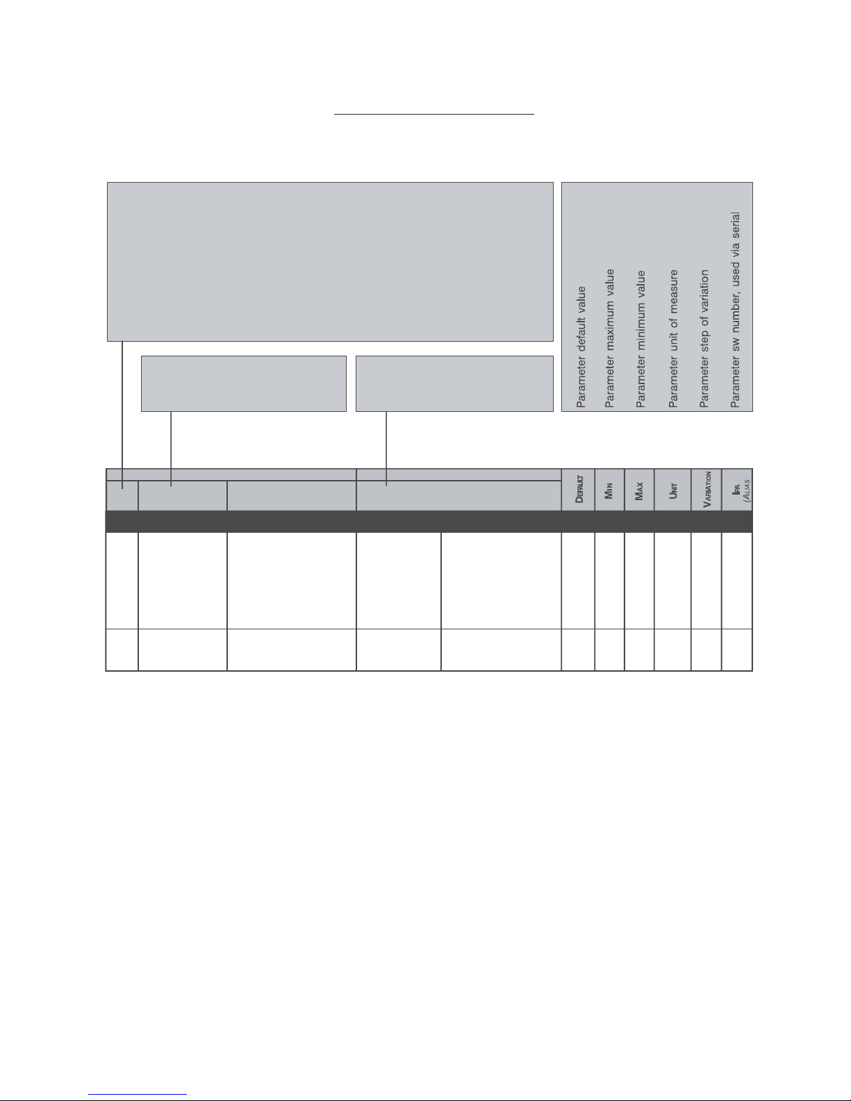
AGy -L 223
12 - Parameter list
Figure 12.1: Parameters Description Legend
ÝÑÜÛæп®¿³»¬»®Ý±¼»ô-¸±©»¼±²¼·-°´¿§ò
Ъ±®³¿¬гИтЗЗЗж
ÈãÓ»²«
¼гЬЧНРФЯЗ
НгНМЯОМЛР
ЧгЧТМЫОЪЯЭЫ
ЪгЪОЫПъОЯУРН
РгРЯОЯУЫМЫО
ЯгЯРРФЧЭЯМЧСТ
ЭгЭСУУЯТЬ
ШгШЧЬЬЫТ
ЗЗЗгР¿®¿³»¬»®²«³¾»®
Нтррр
Нтррп
Ó¿·²-ª±´¬¿¹»
Ó¿·²-º®»¯«»²½§
כּ¼ª¿´«»±º¬¸»´·²»
ª±´¬¿¹»
כּ¼ª¿´«»±º¬¸»´·²»
º®»¯«»²½§
îíð
íèð
ìðð
ìîð
ììð
ìêð
ìèð
ëð
êð
ëðئ
êðئ
Ê
ئ
ìðì
шРтрорч
ìðë
шРтропч
НМЯОМуЛР
ÝÑÜÛ ÔÝÜ ЬЧНРФЯЗ
РЯОЯУЫМЫОРЧЭХФЧНМ
ÜЫНЭОЧРМЧСТ
ÅÝÑÜÛÃ
ÔÝÜÍЫФЫЭМЧСТ
ÜЫНЭОЧРМЧСТ
ÅÝÑÜÛÃæÐ×ÝÕ ÔЧНМЭСЬЫ ÅЧТЮОЯХЫМ Ã
ÔÝÜÍЫФЫЭМЧСТæ ÌЫИМСТЬЧНРФЯЗ
ÔÝÜ ЬЧНРФЯЗ æп®¿³»¬»®²¿³»ô
-¸±©»¼±²¼·-°´¿§
мрронрмир
лрлркр
Note!
(ALIAS):On STARTUP menu only.
Parameter code of same parameter on other menu .
(*): Parameter value depends on the drive size.
(1):KBG-LCD-.. keypad:“Confirm? NO”
KBG-1 keypad:“off”
(2):LCD keypad:“Confirm? YES”
KBG-1 keypad: “do”
Page 48

224 AGy -L
ФЭЬЬ·-°´¿§ЬЫНЭОЧРМЧСТФЭЬН»´»½¬·±²Ь»-½®·°¬·±²
×Ðß
РЯОЯУЫМЫОРЧЭХФЧНМ
¼трррС«¬°«¬º®»¯«»²½§Ъ®»¯«»²¦¿¼·«-½·¬¿
Ш¦ртрпррп
¼тррпЪ®»¯«»²½§®»ºО·º»®·³»²¬±¼·º®»¯«»²¦¿
Ш¦ртрпрро
¼трроС«¬°«¬½«®®»²¬Э±®®»²¬»¼·«-½·¬¿ш®³-ч
Яртпррн
¼тррнС«¬°«¬ª±´¬¿¹»М»²-·±²»¼·«-½·¬¿ш®³-ч
Кпррм
¼тррмЬЭ´·²µª±´¬¿¹»М»²-·±²»¼·ЬЭЮ«-шЬЭч
Кпррл
¼тррлР±©»®º¿½¬±®Ъ¿¬¬±®»¼·°±¬»²¦¿шЭ±-°¸·ч
ртрпррк
¼трркР±©»®ЕµЙГР±¬»²¦¿¼·«-½·¬¿¼»´´щ·²ª»®¬»®
µЙртрпррй
¼тррйС«¬°«¬-°»»¼К»´±½·¬¿А¼»´³±¬±®»
³³ñ-ïððè
¼трриН°»»¼®»ºО·º»®·³т¼·ª»´±½·¬@¼»´¼®·ª»ш¼тррпчцшРткррч
³³ñ-ïððç
¼трлрШ»¿¬-·²µ¬»³°М»³°»®¿¬«®¿¼»´¼·--·°¿¬±®»ш³·-«®¿¬¿¼¿-»²-±®»´·²»¿®»ч
pЭпрпр
¼трлпЬ®·ª»СФН±ª®¿½½¿®·½±¼»´¼®·ª»шпррыг-±¹´·¿¼·¿´´¿®³»ч
ыртпрпп
¼трлоУ±¬±®СФН±ª®¿½½¿®·½±³±¬±®»шпррыг-±¹´·¿¿´´¿®³»ч
ыртпрпо
¼трлнЮ®¿µ»®»-СФН±ª®¿½½т®»-·-¬»²¦¿º®»²¿¬«®¿шпррыг-±¹´·¿¿´´¿®³»ч
ыртпрпн
¼тпррЬ·¹·²°-¬¿¬«-Н¬¿¬±·²¹®»--·¼·¹·¬т¿¾·´·¬¿¬·ш³±®-»¬¬·»®¿±ª·®¬«¿´·ч
ðïì
¼тпрпМ»®³·²°-¬¿¬«-Н¬¿¬±·²¹®»--·¼·¹·¬¿´·-«´´¿³±®-»¬¬·»®¿¼»´´¿-½¸»¼¿¼·
®»¹±´¿¦·±²»
ðïë
¼тпроК·®¼·¹·²°-¬¿¬Н¬¿¬±·²¹®»--·¼·¹·¬¿´·ª·®¬«¿´·¼¿´·²»¿-»®·¿´»±¾«-¼·½¿³°±
ðïê
¼тпорЫ¨°¼·¹·²°-¬¿¬Н¬¿¬±·²¹®»--·¼·¹·¬¿´·±°¦·±²¿´·ш³±®-»¬¬·»®¿±°¦·±²¿´»±ª·®¬«¿´·ч
ðïé
¼тпопЫ¨°¬»®³·²°Н¬¿¬±·²¹®»--·¼·¹·¬¿´·-«´´¿³±®-»¬¬·»®¿¼»´´¿-½¸»¼¿±°¦·±²¿´»
ðïè
¼тпооК·®»¨°¼·¹·²°Н¬¿¬±·²¹®»--·¼·¹·¬¿´·ª·®¬«¿´·±°¦·±²¿´·¼¿´·²»¿-»®·¿´»±¾«-¼·
½¿³°±
ðïç
¼тплрЬ·¹±«¬-¬¿¬«-Н¬¿¬±«-½·¬»¼·¹·¬¿´·-«´´¿³±®-»¬¬·»®¿¼»´´¿-½¸»¼¿¼·
®»¹±´¿¦·±²»ø½±³¿²¼¿¬»¼¿´´¿º«²¦·±²»¼®·ª»±ª·®¬«¿´»÷
ðîð
¼тплпЬ®ª¼·¹±«¬-¬¿Н¬¿¬±«-½·¬»¼·¹·¬¿´·½±³¿²¼¿¬»¼¿´´¿º«²¦·±²»¼»´¼®·ª»
ðîï
¼тплоК·®¼·¹±«¬-¬¿Н¬¿¬±«-½·¬»¼·¹·¬¿´·ª·®¬«¿´·½±³¿²¼¿¬»ª·¿´·²»¿-»®·¿´»±¾«-¼·
½¿³°±
ðîî
¼тпйрЫ¨°¼·¹±«¬-¬¿Н¬¿¬±»-°¿²-·±²»«-½·¬»¼·¹·¬¿´·-«´´¿³±®-»¬¬·»®¿¼»´´¿-½¸»¼¿¼·
®»¹±´¿¦·±²»½±³¿²¼¿¬»¼¿´´¿º«²¦·±²»¼®·ª»±ª·®¬«¿´»÷
ðîí
¼тпйпЫ¨°Ь®ªЬ·¹С«¬Н¬¿Н¬¿¬±»-°¿²-·±²»«-½·¬»¼·¹·¬¿´·½±³¿²¼¿¬»¼¿´´¿º«²¦·±²»¼»´
¼®·ª»
ðîì
¼тпйоЫ¨°К·®Ь·¹С«¬Н¬¿Н¬¿¬±»-°¿²-·±²»«-½·¬»¼·¹·¬¿´·ª·®¬«¿´·½±³¿²¼¿¬»ª·¿´·²»¿
-»®·¿´»±¾«-¼·½¿³°±
ðîë
¼торрЯ²·²п½²º³±²
ÅðÃÒ«´´º«²½¬ рок
ЕпГЪ®»¯®»ºп
ЕоГЪ®»¯®»ºо
ЕнГЮ-¬´»ªº¿½¬
ЕмГСМ´»ªº¿½¬
ЕлГК®»¼´»ªº¿½
ЕкГЬЭЮ´»ªº¿½¬
ЕйГО¿³°Ы¨¬º¿½¬
ЕиГЪ®»¯О»ºº¿½¬
ЕзГН°¼РЧФ·³Ъ¿½
ЕпрГУ´¬Ъ®¯½¸п
ЕппГУ´¬Ъ®¯½¸о
¼торпЯ²·²п³±²·¬±®Н»¹²¿´»¼щ«-½·¬¿шыч¼»´¾´±½½±¼»´´щ·²¹®»--±¿²¿´±¹·½±п
ðîé
¼тороЯ²·²п¬»®³³±²Н»¹²¿´»·²³±®-»¬¬·»®¿шыч¼»´´щ·²¹®»--±¿²¿´±¹·½±п
ðîè
¼топрЯ²·²о½²º³±²Р®±¹®¿³³¿¦·±²»·²¹®»--±¿²¿´±¹·½±ое³±-¬®¿´¿º«²¦·±²»
¿--±½·¿¬¿¿¯«»-¬±·²¹®»--±¿²¿´±¹·½±
ݱ³»°»®¼òîðð ðîç
¼топпЯ²·²о³±²·¬±®Н»¹²¿´»¼щ«-½·¬¿шыч¼»´¾´±½½±¼»´´щ·²¹®»--±¿²¿´±¹·½±о
ðíð
¼топоЯ²·²о¬»®³³±²Н»¹²¿´»·²³±®-»¬¬·»®¿шыч¼»´´щ·²¹®»--±¿²¿´±¹·½±о
ðíï
¼тоорЯ²·²н½²º³±²Р®±¹®¿³³¿¦·±²»·²¹®»--±¿²¿´±¹·½±не³±-¬®¿´¿º«²¦·±²»
¿--±½·¿¬¿¿¯«»-¬±·²¹®»--±¿²¿´±¹·½±
ݱ³»°»®¼òîðð ðíî
¼тоопЯ²·²н³±²·¬±®Н»¹²¿´»¼щ«-½·¬¿ы¼»´¾´±½½±¼»´´щ·²¹®»--±¿²¿´±¹·½±н
ðíí
¼тоооЯ²·²н¬»®³³±²Н»¹²¿´»·²³±®-»¬¬·»®¿шыч¼»´´щ·²¹®»--±¿²¿´±¹·½±н
ðíì
¼толрФЭЙМ±РФЭшруйчК»®·º·½¿¼»·¾·¬¼·½±²¬®±´´±·²ª·¿¬·¿´-»¯«»²½»®·²¬»®²±т
Þ·¬¼¿ð¿éò
êê
¼толпФЭЙМ±РФЭшиуплчК»®·º·½¿¼»·¾·¬¼·½±²¬®±´´±·²ª·¿¬·¿´-»¯«»²½»®·²¬»®²±т
Þ·¬¼¿è¿ïëò
êé
¼толоФЭЙЪ®РФЭшруйчК»®·º·½¿¼»·¾·¬¼·½±²¬®±´´±¹»²»®¿¬·¼¿´-»¯«»²½»®·²¬»®²±т
Þ·¬¼¿ð¿é
êè
ЬЧНРФЯЗ
Ü»-¬·²¿¦·±²»·²¹®»--±¿²¿´±¹·½±ï媷-«¿´·¦¦¿´¿º«²¦·±²»
¿--±½·¿¬¿¿´´ù·²¹®»--±¿²¿´±¹·½±
Page 49

AGy -L 225
ФЭЬЬ·-°´¿§ЬЫНЭОЧРМЧСТФЭЬН»´»½¬·±²Ь»-½®·°¬·±²
×Ðß
РЯОЯУЫМЫОРЧЭХФЧНМ
¼толнФЭЙЪ®РФЭшиуплчУ±²·¬±®±º¬¸»½±²¬®±´¾·¬-¹»²»®¿¬»¼¾§¬¸»·²¬»®²¿´-»¯«»²½»®т
Þ·¬è¬±ïë
êç
¼толмФЭЙЪ®РФЭшпкуомчУ±²·¬±®±º¬¸»½±²¬®±´¾·¬-¹»²»®¿¬»¼¾§¬¸»·²¬»®²¿´-»¯«»²½»®т
Þ·¬ïꬱîì
éð
¼толлФНЙшруйчУ±²·¬±®±º¬¸»¼®·ª»-¬¿¬«-тЮ·¬р¬±й
éï
¼тнррЫ²½Р«´-»-сН¿³°´»Т«³¾»®±º»²½±¼»®°«´-»-ф®»½±®¼»¼·²¬¸»¬·³»·²¬»®ª¿´¼»º·²»¼
¾§°¿®¿³»¬»®Чтлрмт
пспрррнл
¼тнрпЫ²½±¼»®º®»¯Ы²½±¼»®º®»¯«»²½§®»¿¼·²¹шУ±¬±®º®»¯«»²½§ч
Ш¦ртрпрнк
¼тнроЫ²½±¼»®-°»»¼Ы²½±¼»®-°»»¼®»¿¼·²¹ш¼трррчцшРткррч
ртрпспрнй
¼тнлрС°¬·±²п-¬¿¬»Ь®·ª»±°¬·±²п-¬¿¬»ш»¨°¿²-·±²¾±¿®¼¬§°»°®±¹®¿³³»¼ч
ðíè
¼тнлпС°¬·±²о-¬¿¬»Ь®·ª»±°¬·±²о-¬¿¬»ш»¨°¿²-·±²¾±¿®¼¬§°»°®±¹®¿³³»¼ч
ðíç
¼тнлнН¾·-¬¿¬»
ðÉ¿·¬°¿®¿³»¬®·¦¿¬·±²ðëç
ïÉ¿·¬½±²º·¹«®¿¬·±²
îÜ¿¬¿»¨½¸¿²¹»
íÛ®®±®
¼тнлмН¾·¾¿«¼®¿¬»
ðïîÓ¾·¬ñ-ðêð
ïêÓ¾·¬ñ-
îíÓ¾·¬ñ-
нптлУ¾·¬с-
млррХ¾·¬с-
лпийтлХ¾·¬с-
кзнтйлХ¾·¬с-
ймлтмлХ¾·¬с-
ипзтоХ¾·¬с-
ï뫲µ²±©²
¼тмррРЧЬ®»º»®»²½»РЧЬ®»º»®»²½»-·¹²¿´
ыртпрмп
¼тмрпРЧЬº»»¼¾¿½µРЧЬº»»¼¾¿½µ-·¹²¿´
ыртпрмо
¼тмроРЧЬ»®®±®РЧЬ»®®±®-·¹²¿´
ыртпрмн
¼тмрнРЧЬ·²¬»¹®½±³°РЧЬ·²¬»¹®¿´½±³°±²»²¬
ыртпрмм
¼тмрмРЧЬ±«¬°«¬РЧЬ±«¬°«¬-·¹²¿´
ыртпрмл
¼тмлрУ¼°´½»®®±®Н¬¿¬«-±º·²¬»®²¿´-»¯«»²½»®
ðÒ±»®®±®
ïײ¬»®²¿´-»¯«»²½»®»®®±®êî
¼тлррФ·º¬-°¿½»Н°¿½»²»»¼»¼¬±¿½½»´»®¿¬»¬¸»½¿®º®±³¦»®±¬±³¿¨-°»»¼
¿²¼¬¸»²¼»½»´»®¿¬»¾¿½µ¬±¦»®±
ртрпкн
¼тлрпФ·º¬¿½½»´-°¿½»Н°¿½»²»»¼»¼¬±¿½½»´»®¿¬»¬¸»½¿®º®±³¦»®±¬±³¿¨-°»»¼
ртрпкм
¼тлроФ·º¬¼»½»´-°¿½»Н°¿½»²»»¼»¼¬±¼»½»´»®¿¬»¬¸»½¿®º®±³³¿¨-°»»¼¬±¦»®±
ртрпкл
¼тиррп-¬¿´¿®³у´¿¬»-¬Ф¿-¬¿´¿®³-¬±®»¼¾§¬¸»¼®·ª»¿´¿®³´·-¬
Н»»°¿®¿¹®¿°¸зтнрмк
¼тирпо²¼¿´¿®³Н»½±²¼¬±´¿-¬¿´¿®³
ðìé
¼тирон®¼¿´¿®³М¸·®¼¬±´¿-¬¿´¿®³
ðìè
¼тирнм¬¸¿´¿®³Ъ±«®¬¸¬±´¿-¬¿´¿®³
ðìç
¼тзлрЬ®·ª»®¿¬»¼½«®®Ь®·ª»®¿¬»¼½«®®»²¬ш·¬¼»°»²¼-±²¬¸»¼®·ª»-·¦»ч
ртпрлр
¼тзлпНЙª»®-·±²шпсочН±º¬©¿®»ª»®-·±²у°¿®¬п
рнтрп ртрпрлп
¼тзлоНЙª»®-·±²шосочН±º¬©¿®»ª»®-·±²у°¿®¬о
рртрр ртрпрло
¼тзлйЬ®·ª»-·¦»Ь®·ª»-·¦»½±¼»
рртйлµЙуонрсмррсмкрКрлй
пптлµЙуонрсмррсмкрК
оотоµЙуонрсмррсмкрК
ннµЙуонрсмррсмкрК
ммµЙуонрсмррсмкрК
ллтлµЙуонрсмррсмкрК
кйтлµЙуонрсмррсмкрК
йппµЙуонрсмррсмкрК
иплµЙуонрсмррсмкрК
зооµЙуонрсмррсмкрК
прнрµЙуонрсмррсмкрК
ппнйµЙуонрсмррсмкрК
помлµЙуонрсмррсмкрК
пнллµЙуонрсмррсмкрК
пмйлµЙуонрсмррсмкрК
плзрµЙуонрсмррсмкр
пкппрµЙуонрсмррсмкрК
пйпноµЙуонрсмррсмкрК
пипкрµЙуонрсмррсмкрК
оппитлµЙуонрсмррмкр
олоррµЙуонрсмррмкр
¼тзлиЬ®·ª»½º¹¬§°»Ь®·ª»½±²º·¹«®¿¬·±²¬§°»
ÅðÃͬ¿²¼¿®¼æìðð
ÅïÃß³»®·½¿²æìêð
Н¬¿²¼¿®¼жмррК¿½флрШ¦
Я³»®·½¿²жмкрК¿½фкрШ¦
ðêï
¼тзззЬ·-°´¿§М»-¬Ь®·ª»¼·-°´¿§¬»-¬
ðçç
ݱ³³«²·½¿¬·±²-°»»¼¾»¬©»»²ÍÞ׿²¼Ó¿-¬»®
ݱ³³«²·½¿¬·±²-¬¿¬»¾»¬©»»²ÍÞ׿²¼Ó¿-¬»®
Page 50

226 AGy -L
ФЭЬЬ·-°´¿§ЬЫНЭОЧРМЧСТФЭЬН»´»½¬·±²Ь»-½®·°¬·±²
×Ðß
РЯОЯУЫМЫОРЧЭХФЧНМ
НтрррУ¿·²-ª±´¬¿¹»О¿¬»¼ª¿´«»±º¬¸»´·²»ª±´¬¿¹»
онрмрронрмирК
íèð
ìðð
ìîð
ììð
ìêð
ìèð
НтррпУ¿·²-º®»¯«»²½§О¿¬»¼ª¿´«»±º¬¸»´·²»º®»¯«»²½§
лрлрлркрШ¦
êð
НтпррЮ¿-»ª±´¬¿¹»У±¬±®¾¿-»ш®¿¬»¼чª±´¬¿¹»
нирлрлоиКпмпн
шРтркпч
НтпрпЮ¿-»º®»¯«»²½§О¿¬»¼º®»¯«»²½§±º¬¸»³±¬±®
лрололрШ¦ртпмпм
шРтркоч
НтплрУ±¬±®®¿¬»¼½«®®О¿¬»¼½«®®»²¬±º¬¸»³±¬±®
шцчшцчшцчЯртпмрк
шРтрмрч
НтплпУ±¬±®°±´»°¿·®-Р±´»Р¿·®-±º¬¸»³±¬±®
опкрртрпмрй
шРтрмпч
НтплоУ±¬±®°±©»®º¿½¬У±¬±®°±©»®º¿½¬±®
шцчртрппртрпмри
шРтрмоч
НтплнУ±¬±®-¬¿¬±®ОУ»¿-«®»³»²¬±º¬¸»-¬¿¬±®®»-·-¬¿²½»±º¬¸»³±¬±®
шцчрззтзз±¸³мрз
шРтрмнч
НтпйрУ»¿-«®»-¬¿¬±®ОУ±¬±®Я«¬±¬«²»½±³³¿²¼
шпчшпчшпчшоч
øî÷
НтпирЭ¿®³¿¨-°»»¼Н°»»¼±º¬¸»´·º¬½¿®©¸»²¬¸»·²ª»®¬»®±«¬°«¬º®»¯«»²½§·-»¯«¿´
¬±Нтпрп
ртлрртрплтрр³с-ртрппнон
шЯтрзрч
НторрЪ®»¯«»²½§®»ºрЬ·¹·¬¿´®»º»®»²½»º®»¯«»²½§р
пртруЪтрорЪтрорнппшЪтпррч
НторпЪ®»¯«»²½§®»ºпЬ·¹·¬¿´®»º»®»²½»º®»¯«»²½§п
лртруЪтрорЪтрорнпошЪтпрпч
НтороЪ®»¯«»²½§®»ºоЬ·¹·¬¿´®»º»®»²½»º®»¯«»²½§о
руЪтрорЪтрорнпншЪтпроч
НторнЪ®»¯«»²½§®»ºнЬ·¹·¬¿´®»º»®»²½»º®»¯«»²½§н
руЪтрорЪтрорнпмшЪтпрнч
НтормЪ®»¯«»²½§®»ºмЬ·¹·¬¿´®»º»®»²½»º®»¯«»²½§м
руЪтрорЪтрорнплшЪтпрмч
НторлЪ®»¯«»²½§®»ºлЬ·¹·¬¿´®»º»®»²½»º®»¯«»²½§л
руЪтрорЪтрорнпкшЪтпрлч
НторкЪ®»¯«»²½§®»ºкЬ·¹·¬¿´®»º»®»²½»º®»¯«»²½§к
руЪтрорЪтрорнпйшЪтпркч
НторйЪ®»¯«»²½§®»ºйЬ·¹·¬¿´®»º»®»²½»º®»¯«»²½§й
руЪтрорЪтрорнпишЪтпрйч
НтоорН³±±¬¸-¬¿®¬º®¯Ъ®»¯«»²½§®»º»®»²½»¼«®·²¹-³±±¬¸-¬¿®¬
отруЪтрорЪтрорнойшЪтппкч
НтоолО¿³°º¿½¬±®пУ«´¬·°´·»®º±®¿½½с¼»½¿²¼¶»®µ-±º®¿³°-»¬-п¿²¼н
птррртрпотлрртрппном
шЯтрзпч
НтоокО¿³°º¿½¬±®оУ«´¬·°´·»®º±®¿½½с¼»½¿²¼¶»®µ-±º®¿³°-»¬-о¿²¼м
птррртрпотлрртрппной
шЯтрзоч
НтонрЦ»®µ¿½½·²·пЦ»®µ¿°°´·»¼¿¬¬¸»¾»¹·²²·²¹±º¿²¿½½»´»®¿¬·±²©·¬¸®¿³°-»¬п
ртлрртрппртрр
³ñ-
í
ртрпнмншЪтолпч
НтонпЯ½½»´»®¿¬·±²пФ·²»¿®¿½½»´»®¿¬·±²©·¬¸®¿³°-»¬п
рткрртрплтрр
³ñ-
î
ртрпнозшЪторпч
НтоноЦ»®µ¿½½»²¼пЦ»®µ¿°°´·»¼¿¬¬¸»»²¼±º¿²¿½½»´»®¿¬·±²©·¬¸®¿³°-»¬п
птмрртрппртрр
³ñ-
í
ртрпнммшЪтолоч
НтоннЦ»®µ¼»½·²·пЦ»®µ¿°°´·»¼¿¬¬¸»¾»¹·²²·²¹±º¿¼»½»´»®¿¬·±²©·¬¸®¿³°-»¬п
птмрртрппртрр
³ñ-
í
ртрпнмлшЪтолнч
НтонмЬ»½»´»®¿¬·±²пФ·²»¿®¼»½»´»®¿¬·±²©·¬¸®¿³°-»¬п
рткрртрплтрр
³ñ-
î
ртрпннршЪтороч
НтонлЦ»®µ¼»½»²¼пЦ»®µ¿°°´·»¼¿¬¬¸»»²¼±º¿¼»½»´»®¿¬·±²©·¬¸®¿³°-»¬п
птррртрппртрр
³ñ-
í
ртрпнмкшЪтолмч
НтомрЦ»®µ¿½½·²·оЦ»®µ¿°°´·»¼¿¬¬¸»¾»¹·²²·²¹±º¿²¿½½»´»®¿¬·±²©·¬¸®¿³°-»¬о
птррртрппртрр
³ñ-
í
ртрпнмйшЪтоллч
НтомпЯ½½»´»®¿¬·±²оФ·²»¿®¿½½»´»®¿¬·±²©·¬¸®¿³°-»¬о
рткрртрплтрр
³ñ-
î
ртрпннпшЪторнч
НтомоЦ»®µ¿½½»²¼оЦ»®µ¿°°´·»¼¿¬¬¸»»²¼±º¿²¿½½»´»®¿¬·±²©·¬¸®¿³°-»¬о
птмрртрппртрр
³ñ-
í
ртрпнмишЪтолкч
НтомнЦ»®µ¼»½·²·оЦ»®µ¿°°´·»¼¿¬¬¸»¾»¹·²²·²¹±º¿¼»½»´»®¿¬·±²©·¬¸®¿³°-»¬о
птмрртрппртрр
³ñ-
í
ртрпнмзшЪтолйч
НМЯОМуЛР
ìðì
шРтрорч
ìðë
шРтропч
èðê
шЭтпррч
Page 51

AGy -L 227
ФЭЬЬ·-°´¿§ЬЫНЭОЧРМЧСТФЭЬН»´»½¬·±²Ь»-½®·°¬·±²
×Ðß
РЯОЯУЫМЫОРЧЭХФЧНМ
НтоммЬ»½»´»®¿¬·±²оФ·²»¿®¼»½»´»®¿¬·±²©·¬¸®¿³°-»¬о
рткрртрплтрр
³ñ-
î
ртрпнношЪтормч
НтомлЦ»®µ¼»½»²¼оЦ»®µ¿°°´·»¼¿¬¬¸»»²¼±º¿¼»½»´»®¿¬·±²©·¬¸®¿³°-»¬о
птррртрппртрр
³ñ-
í
ртрпнлршЪтолич
НтолрЭ±²¬½´±-»¼»´¿§ОЛТ½±²¬¿½¬±®½´±-»¼»´¿§
рторрпр-ртрппнпк
шЯтрирч
НтолпУ¿¹²»¬¬·³»У±¬±®³¿¹²»¬·¦¿¬·±²¬·³»
прпр-ртрппнпй
шЯтрипч
НтолоЮ®¿µ»±°»²¼»´¿§Ю®¿µ»½±²¬¿½¬±®±°»²¼»´¿§
рторрпр-ртрппнпи
шЯтриоч
НтолнН³±±¬¸-¬¿®¬¼´§Н³±±¬¸-¬¿®¬¼«®¿¬·±²
ррпр-ртрппнпз
шЯтринч
НтолмЬЭЮ®¿µ»-¬°¬·³»Ь«®¿¬·±²±ºрШ¦¾®¿µ·²¹¿¬-¬±°
прпр-ртрппнор
шЯтримч
НтоллЮ®¿µ»½´±-»¼´§Ю®¿µ»½±²¬¿½¬±®½´±-»¼»´¿§
рторрпр-ртрппноп
шЯтрилч
НтолкЭ±²¬±°»²¼»´¿§ОЛТ½±²¬¿½¬±®±°»²¼»´¿§
рторрпр-ртрппноо
шЯтрикч
НтокрФ·º¬-¬±°³±¼»Ф·º¬¾»¸¿ª·±®¿¬-¬±°
ÅðÃܽ¾¿¬-¬±°Üݾ®¿µ»·-°»®º±®³»¼¿º¬»®¬¸»
±«¬°«¬º®»¯«»²½§·-¾»´±©Ртммр
¬¸®»-¸±´¼
ïðï
ÅïÃÒ±®³¿´-¬±°Üݾ®¿µ»·-²±¬°»®º±®³»¼¿¬
-¬±°
НтнррУ¿²«¿´¾±±-¬ЕыГУ¿²«¿´¾±±-¬¿¬´±©®»ª±´«¬·±²-
нтрртролтры±ºНтпррртпмопшРтпорч
НтнрпЯ«¬±¾±±-¬»²Я«¬±³¿¬·½¾±±-¬º«²½¬·±²»²¿¾´·²¹
ÅðÃÜ·-¿¾´»ððï
ÅïÃÛ²¿¾´»
НтнпрН´·°½±³°»²-¿¬Я³±«²¬±º-´·°½±³°»²-¿¬·±²¼«®·²¹³±¬±®·²¹
лрролры±º
®¿¬»¼-´·°
пмпзшРтпррч
НтнппН´·°½±³°®»¹»²Я³±«²¬±º-´·°½±³°»²-¿¬·±²¼«®·²¹®»¹»²»®¿¬·±²
лрролры±º
®¿¬»¼-´·°
плрршРтпроч
НтнпоН´·°½±³°º·´¬»®М·³»½±²-¬¿²¬±º-´·°½±³°»²-¿¬·±²
ртнрпр-ртпморшРтпрпч
НтнорЬЭ¾®¿µ·²¹´»ª»´Э«®®»²¬´»ª»´«-»¼¼«®·²¹ЬЭ¾®¿µ»¿¬-¬¿®¬¿²¼-¬±°
йлрпрры±º¼тзлрпммзшРтнррч
НтмррЭ±²¬®±´³±¼»Ь®·ª»½±²¬®±´³±¼»
ЕрГКсºС°»²Ф±±°Н°»»¼½±²¬®±´©·¬¸±«¬»²½±¼»®
º»»¼¾¿½µ
ððï
ЕпГКсºЭ´-¼Ф±±°Н°»»¼½±²¬®±´©·¬¸»²½±¼»®
º»»¼¾¿½µ
НтмрпЫ²½±¼»®°°®Р«´-»-°»®®»ª±´«¬·±²±º¬¸»»²½±¼»®·²«-»
промпззззпплпшЧтлрпч
НтмлрН°¼½¬®´Ру¹¿·²ФН°»»¼´±±°Р®±°±®¬·±²¿´¹¿·²
отррпррыртплрншРтпйоч
НтмлпН°¼½¬®´Чу¹¿·²ФН°»»¼´±±°Ч²¬»¹®¿´¹¿·²
птррпррыртплрмшРтпйнч
НтмлоН°¼РЧШ·¹¸´·³Н°»»¼РЧ®»¹«´¿¬±®±«¬°«¬«°°»®´·³·¬
пррпрры±ºЪтрорртплрзшРтпйкч
НтмлнН°¼РЧФ±©´·³Н°»»¼РЧ®»¹«´¿¬±®±«¬°«¬´±©»®´·³·¬
упрупррры±ºЪтрорртплпршРтпййч
НтзрпН¿ª»°¿®¿³»¬»®-Н¿ª»°¿®¿³»¬»®-
шпчшпчшпчшоч
øî÷
ЧтрррЫ²¿¾´»-®½Н±«®½»±º¬¸»Ы²¿¾´»½±³³¿²¼±ºФ·º¬Э±²¬®±´Й±®¼
ЕрГЪ¿´-»М¸»½±³³¿²¼·-²»ª»®¿½¬·ª»оролпрр
ÅïÃÌ®«»Ì¸»½±³³¿²¼·-¿´©¿§-¿½¬·ª»
ЕоГЬЧпМ¸»½±³³¿²¼½±³»-º®±³
Ü·¹×²°ï
ЕнГЬЧоМ¸»½±³³¿²¼½±³»-º®±³
Ü·¹×²°î
ЕмГЬЧнМ¸»½±³³¿²¼½±³»-º®±³
Ü·¹×²°í
ЕлГЬЧмМ¸»½±³³¿²¼½±³»-º®±³
Ü·¹×²°ì
ïíëð
шЯтоорч
моншРтпооч
мзишРтрпрч
èðð
шЭтрррч
ЧТМЫОЪЯЭЫ
Page 52

228 AGy -L
ФЭЬЬ·-°´¿§ЬЫНЭОЧРМЧСТФЭЬН»´»½¬·±²Ь»-½®·°¬·±²
×Ðß
РЯОЯУЫМЫОРЧЭХФЧНМ
ЕкГЬЧлМ¸»½±³³¿²¼½±³»-º®±³
Ü·¹×²°ë
ЕйГЬЧкМ¸»½±³³¿²¼½±³»-º®±³
Ü·¹×²°ê
ЕиГЬЧйМ¸»½±³³¿²¼½±³»-º®±³
Ü·¹×²°é
ЕзГЬЧиМ¸»½±³³¿²¼½±³»-º®±³
Ü·¹×²°è
ЕпрГЬЧЫ¨°пМ¸»½±³³¿²¼½±³»-º®±³Ы¨°ЬЧ
ï
ЕппГЬЧЫ¨°оМ¸»½±³³¿²¼½±³»-º®±³Ы¨°ЬЧ
î
ЕпоГЬЧЫ¨°нМ¸»½±³³¿²¼½±³»-º®±³Ы¨°ЬЧ
í
ЕпнГЬЧЫ¨°мМ¸»½±³³¿²¼½±³»-º®±³Ы¨°ЬЧ
ì
ЕпмГЯТЬпМ¸»½±³³¿²¼½±³»-º®±³¬¸»
±«¬°«¬±º¬¸»¾´±½µßÒÜï
ЕплГЯТЬоМ¸»½±³³¿²¼½±³»-º®±³¬¸»
±«¬°«¬±º¬¸»¾´±½µßÒÜî
ЕпкГЯТЬнМ¸»½±³³¿²¼½±³»-º®±³¬¸»
±«¬°«¬±º¬¸»¾´±½µßÒÜí
ЕпйГСОпМ¸»½±³³¿²¼½±³»-º®±³¬¸»
±«¬°«¬±º¬¸»¾´±½µÑÎï
ЕпиГСОоМ¸»½±³³¿²¼½±³»-º®±³¬¸»
±«¬°«¬±º¬¸»¾´±½µÑÎî
ЕпзГСОнМ¸»½±³³¿²¼½±³»-º®±³¬¸»
±«¬°«¬±º¬¸»¾´±½µÑÎí
ЕорГТСМпМ¸»½±³³¿²¼½±³»-º®±³¬¸»
±«¬°«¬±º¬¸»¾´±½µÒÑÌï
ЕопГТСМоМ¸»½±³³¿²¼½±³»-º®±³¬¸»
±«¬°«¬±º¬¸»¾´±½µÒÑÌî
ЕооГТСМнМ¸»½±³³¿²¼½±³»-º®±³¬¸»
±«¬°«¬±º¬¸»¾´±½µÒÑÌí
ЕонГТСМмМ¸»½±³³¿²¼½±³»-º®±³¬¸»
±«¬°«¬±º¬¸»¾´±½µÒÑÌì
ЕомГЪ®¯Н»´³¿¬½¸М¸»½±³³¿²¼·-½±³·²¹º®±³¬¸»
±«¬°«¬±º¬¸»¾´±½µÚ®»¯Í»´
³¿¬½¸
ЕолГН¸±®¬Ъ´±±®Ъ´М¸»½±³³¿²¼·-¬¸»-¸±®¬º´±±®
º´¿¹
ЧтррпО«²Ъ©¼-®½Н±«®½»±º¬¸»О«²Ъ±®©¿®¼½±³³¿²¼±ºФЭЙ
Я-º±®Чтрррнролпрп
ЧтрроО«²О»ª-®½Н±«®½»±º¬¸»О«²О»ª»®-»½±³³¿²¼±ºФЭЙ
Я-º±®Чтрррмролпро
ЧтррнЪ®»¯Н»´п-®½Н±«®½»±º¬¸»Ъ®»¯«»²½§Н»´»½¬±®п±ºФЭЙ
Я-º±®Чтрррлролпрн
ЧтррмЪ®»¯Н»´о-®½Н±«®½»±º¬¸»Ъ®»¯«»²½§Н»´»½¬±®о±ºФЭЙ
Я-º±®Чтррркролпрм
ЧтррлЪ®»¯Н»´н-®½Н±«®½»±º¬¸»Ъ®»¯«»²½§Н»´»½¬±®н±ºФЭЙ
Я-º±®Чтрррйролпрл
ЧтрркЪ®»¯Н»´м-®½Н±«®½»±º¬¸»Ъ®»¯«»²½§Н»´»½¬±®м±ºФЭЙ
Я-º±®Чтррррролпрк
ЧтррйО¿³°Н»´п-®½Н±«®½»±º¬¸»О¿³°Н»´»½¬±®п±ºФЭЙ
Я-º±®Чтррролролпрй
ЧтрриО¿³°Н»´о-®½Н±«®½»±º¬¸»О¿³°Н»´»½¬±®п±ºФЭЙ
Я-º±®Чтррррролпри
ЧтррзЫ¨¬º¿«´¬-®½Н±«®½»±º¬¸»Ы¨¬»®²¿´Ъ¿«´¬½±³³¿²¼±ºФЭЙ
Я-º±®Чтррриролпрз
ЧтрпрЪ¿«´®»-»¬-®½Н±«®½»±º¬¸»Ъ¿«´¬О»-»¬½±³³¿²¼±ºФЭЙ
Я-º±®Чтрррзролппр
ЧтрппЮ¿µ°©®¿½¬-®½Н±«®½»±º¬¸»Ю¿½µ«°Р±©»®Н«°°´§Я½¬·ª»½±³³¿²¼±ºФЭЙ
Я-º±®Чтррррролппп
ЧтрпоЪ±®½»¼-¬±°-®½Н±«®½»±º¬¸»Ъ±®½»¼Н¬±°½±³³¿²¼±ºФЭЙ
рролпил
ЧтпррЬ·¹±«¬°«¬п½º¹Ь·¹·¬¿´±«¬°«¬п½±²º·¹«®¿¬·±²
ЕрГЬ®·ª»О»¿¼§лпрллппо
ÅïÃß´¿®³-¬¿¬»
ÅîÃÒ±¬·²¿´¿®³
ÅíÃÓ±¬±®®«²
ÅìÃÓ±¬±®-¬±°
ЕлГОЫК®±¬¿¬·±²
ÅêÃͬ»¿¼§-¬¿¬»
ÅéÃο³°·²¹
ЕиГЛК®«²²·²¹
Page 53

AGy -L 229
ФЭЬЬ·-°´¿§ЬЫНЭОЧРМЧСТФЭЬН»´»½¬·±²Ь»-½®·°¬·±²
×Ðß
РЯОЯУЫМЫОРЧЭХФЧНМ
ÅçÃÑ«¬¬®¯â¬¸®
ЕпрГЭ«®®»²¬´·³
ЕппГЬЭу´·²µ´·³
ЕпоГФ·³·¬¿½¬·ª»
ЕпнГЯ«¬±½¿°¬®«²
ЕпмГЮЛ±ª»®´±¿¼
ЕплГТ»¹°©®º¿½¬
ЕпкГРЧЬ»®®вд
ЕпйГРЧЬ»®®в¬¸®
ЕпиГРЧЬ»®®д¬¸®
ЕпзГРЧЬ»®вдш·²¸ч
ЕорГРЧЬ»®®вш·²¸ч
ЕопГРЧЬ»®®дш·²¸ч
ЕооГЪЙЬ»²½®±¬
ЕонГОЫК»²½®±¬
ЕомГЫ²½±¼»®-¬±°
ЕолГЫ²½±¼»®®«²
ЕокГЫ¨¬»®²º¿«´¬
ЕойГТ±»¨¬º¿«´¬
ЕоиГН»®·¿´МС
Åîçú®»¯ã¬¸®ï
Åíðú®»¯ÿ㬸®ï
Åíïú®»¯â¬¸®ï
Åíîú®»¯ä¬¸®ï
Åííú®»¯ã¬¸®î
Åíìú®»¯ÿ㬸®î
Åíëú®»¯â¬¸®î
Åíêú®»¯ä¬¸®î
ЕнйГШН¬»³°г¬¸®
ЕниГШН¬»³°яг¬¸®
ЕнзГШН¬»³°в¬¸®
ЕмрГШН¬»³°д¬¸®
ЕмпГС«¬°«¬º®»¯
ЕмоГС«¬º®»¯¨о
ЕмнГЭ±¿-¬М¸®±«¹¸
ЕммГЫ³¹Н¬±°
ЕмлГЬЭ¾®¿µ·²¹
ЕмкГЬ®ªСФ-¬¿¬«-
ЕмйГЬ®ªСФ©¿®²
ЕмиГУ±¬СФ-¬¿¬«-
ЕмзГО»-»®ª»¼
ЕлрГО»-»®ª»¼
ЕлпГЭ±²¬¿½¬±®Я½¬·ª»©¸»²¬¸»ОЛТ½±²¬¿½¬±®
¸¿-¬±¾»½´±-»¼ô»·¬¸»®º±®
«°©¿®¼±®¼±©²©¿®¼³±¬·±²
ЕлоГЭ±²¬¿½¬±®ЛРЯ½¬·ª»©¸»²¬¸»ОЛТ½±²¬¿½¬±®
¸¿-¬±¾»½´±-»¼º±®«°©¿®¼
³±¬·±²
ЕлнГЭ±²¬¿½¬±®ЬЙЯ½¬·ª»©¸»²¬¸»ОЛТ½±²¬¿½¬±®
¸¿-¬±¾»½´±-»¼º±®¼±©²©¿®¼
³±¬·±²
ЕлмГЮ®¿µ»½±²¬Я½¬·ª»©¸»²¬¸»³»½¸¿²·½¿´
¾®¿µ»¸¿-¬±¾»®»´»¿-»¼
ЕллГФ·º¬-¬¿®¬Я½¬·ª»©¸»²¬¸»·²ª»®¬»®±«¬°«¬
¾®·¼¹»·-»²¿¾´»¼¿²¼Üݾ®¿µ»
·-²±¬·²°®±¹®»--
ЧтпрпЬ·¹±«¬°«¬о½º¹Ь·¹·¬¿´±«¬°«¬о½±²º·¹«®¿¬·±²
Я-º±®Чтпррнорллппн
ЧтпроЬ·¹±«¬°«¬н½º¹Ь·¹·¬¿´±«¬°«¬н½±²º·¹«®¿¬·±²
Я-º±®Чтпррлмрллппм
ЧтпрнЬ·¹±«¬°«¬м½º¹Ь·¹·¬¿´±«¬°«¬м½±²º·¹«®¿¬·±²
Я-º±®Чтпррорллппл
ЧтплрЫ¨°Ь·¹С«¬п½º¹Ы¨¬»²¼»¼¼·¹·¬¿´±«¬°«¬п½±²º·¹«®¿¬·±²
Я-º±®Чтпррлорллппк
ЧтплпЫ¨°Ь·¹С«¬о½º¹Ы¨¬»²¼»¼¼·¹·¬¿´±«¬°«¬о½±²º·¹«®¿¬·±²
Я-º±®Чтпррлнрллппй
ЧтплоЫ¨°Ь·¹С«¬н½º¹Ы¨¬»²¼»¼¼·¹·¬¿´±«¬°«¬н½±²º·¹«®¿¬·±²
Я-º±®Чтпррррллпир
ЧторрЯ²·²пМ§°»
ЕрГхсупрКпрпппи
ЕпГрупрКсруор³Я
ЧторпЯ²·²п±ºº-»¬Я²¿´±¹Ч²°«¬п±ºº-»¬
руззтзззтзыртпппз
ЧтороЯ²·²п¹¿·²Я²¿´±¹Ч²°«¬п¹¿·²
пузтзззтззыртрппор
ЧторнЯ²·²п³·²·³«³Я²Ч²°«¬п³·²·³«²ª¿´«»
ррззтззыртппоп
ЧтормЯ²·²пº·´¬»®М·³»½±²-¬¿²¬±º¼·¹·¬¿´º·´¬»®±²Я²¿´±¹·²°«¬п
ртпртррпртол-»½ртррппоо
ЧторлЯ²·²пЬ»¿¼Ю¿²¼Я²¿´±¹Ч²°«¬п¼»¿¼¾¿²¼
ррззтзыртрппио
Í»¬¬·²¹±º¬¸»ß²¿´±¹×²°«¬ï¬§°»®»º»®»²½»øª±´¬¿¹»÷
Þ·°±´¿®oïðÊ
˲·°±´¿®õïðÊ
Page 54

230 AGy -L
ФЭЬЬ·-°´¿§ЬЫНЭОЧРМЧСТФЭЬН»´»½¬·±²Ь»-½®·°¬·±²
×Ðß
РЯОЯУЫМЫОРЧЭХФЧНМ
ЧтопрЯ²·²оМ§°»
ЕрГхсупрКррппон
ЕпГрупрКсруор³Я
ЧтоппЯ²·²о±ºº-»¬Я²¿´±¹Ч²°«¬о±ºº-»¬
руззтзззтзыртппом
ЧтопоЯ²·²о¹¿·²Я²¿´±¹Ч²°«¬о¹¿·²
пузтзззтззыртрппол
ЧтопнЯ²·²о³·²·³«³Я²Ч²°«¬о³·²·³«²ª¿´«»
ррззтззыртрппок
ЧтопмЯ²·²оº·´¬»®М·³»½±²-¬¿²¬±º¼·¹·¬¿´º·´¬»®±²Я²¿´±¹·²°«¬о
ртпртррпртол-»½ртррппой
ЧтоплЯ²·²оЬ»¿¼Ю¿²¼Я²¿´±¹Ч²°«¬о¼»¿¼¾¿²¼
ррззтзыртппин
ЧтоорЯ²·²нМ§°»
ЕпГрупрКсруор³Яппопои
ЕоГмуор³Я
ЧтоопЯ²·²н±ºº-»¬Я²¿´±¹Ч²°«¬н±ºº-»¬
руззтзззтзыртппоз
ЧтоооЯ²·²н¹¿·²Я²¿´±¹Ч²°«¬н¹¿·²
пузтзззтззыртрппнр
ЧтоонЯ²·²н³·²·³«³Я²Ч²°«¬н³·²·³«²ª¿´«»
ррззтззыртрппнп
ЧтоомЯ²·²нº·´¬»®М·³»½±²-¬¿²¬±º¼·¹·¬¿´º·´¬»®±²Я²¿´±¹·²°«¬н
ртпртррпртол-»½ртррппно
ЧтоолЯ²·²нЬ»¿¼Ю¿²¼Я²¿´±¹Ч²°«¬н¼»¿¼¾¿²¼
ррззтзыртппим
ЧтнррЯ²¿´±¹±«¬п½º¹Я²¿´±¹С«¬°«¬п½±²º·¹«®¿¬·±²
ÅðÃÚ®»¯±«¬¿¾-Ñ«¬°«¬Ú®»¯«»²½§¿¾-±´«¬»
ª¿´«»ò
рроопнн
ÅïÃÚ®»¯±«¬Ñ«¬°«¬Ú®»¯«»²½§ò
ÅîÃÑ«¬°«¬½«®®Ñ«¬°«¬Ý«®®»²¬ò
ÅíÃÑ«¬ª±´¬¿¹»Ñ«¬°«¬Ê±´¬¿¹»ò
ÅìÃÑ«¬¬®¯ø°±-÷Ñ«¬°«¬Ì±®¯«»°±-·¬·ª»ª¿´«»ò
ÅëÃÑ«¬¬®¯ø¿¾-÷Ñ«¬°«¬Ì±®¯«»¿¾-±´«¬»ª¿´«»ò
ÅêÃÑ«¬¬®¯Ñ«¬°«¬Ì±®¯«»ò
ÅéÃÑ«¬°©®ø°±-÷Ñ«¬°«¬Ð±©»®°±-·¬·ª»ª¿´«»ò
ÅèÃÑ«¬°©®ø¿¾-÷Ñ«¬°«¬Ð±©»®¿¾-±´«¬»ª¿´«»ò
ÅçÃÑ«¬°©®Ñ«¬°«¬Ð±©»®ò
ЕпрГС«¬РЪС«¬°«¬Р±©»®Ъ¿½¬±®т
ЕппГЫ²½º®»¯¿¾-Ы²½±¼»®º®»¯«»²½§¿¾-±´«¬»
ª¿´«»ò
ЕпоГЫ²½±¼»®º®»¯Ы²½±¼»®º®»¯«»²½§т
ЕпнГЪ®»¯®»º¿¾-Ъ®»¯«»²½§®»º»®»²½»¿¾-±´«¬»
ª¿´«»ò
ЕпмГЪ®»¯®»ºЪ®»¯«»²½§®»º»®»²½»
ЕплГФ±¿¼½«®®»²¬Ф±¿¼Э«®®»²¬т
ЕпкГУ¿¹²½«®®»²¬У±¬±®У¿¹²»¬·¦·²¹Э«®®»²¬т
ЕпйГРЧЬ±«¬°«¬РЧЬ®»¹«´¿¬±®±«¬°«¬т
ЕпиГЬЭ´·²µª±´¬ЬЭ¾«-½¿°¿½·¬±®-´»ª»´т
ЕпзГЛ½«®®»²¬С«¬°«¬°¸¿-»Л½«®®»²¬-·¹²¿´т
ЕорГК½«®®»²¬С«¬°«¬°¸¿-»К½«®®»²¬-·¹²¿´т
ЕопГЙ½«®®»²¬С«¬°«¬°¸¿-»Й½«®®»²¬-·¹²¿´т
ЕооГЪ®»¯®»ºº¿½У«´¬·°´·»®º¿½¬±®º±®º®»¯«»²½§
®»º»®»²½»
ЧтнрпЯ²±«¬п±ºº-»¬Я²¿´±¹±«¬°«¬п±ºº-»¬
рузтзззтззртрппнм
ЧтнроЯ²±«¬п¹¿·²Я²¿´±¹±«¬°«¬п¹¿·²
пузтзззтззртрппнл
ЧтнрнЯ²±«¬пº·´¬»®М·³»½±²-¬¿²¬±º±«¬°«¬º·´¬»®
рротл-»½ртрппнк
ЧтнпрЯ²¿´±¹±«¬о½º¹Я²¿´±¹С«¬°«¬о½±²º·¹«®¿¬·±²
Я-º±®Чтнрророопнй
ЧтнппЯ²±«¬о±ºº-»¬Я²¿´±¹±«¬°«¬о±ºº-»¬
рузтзззтззртрппни
ЧтнпоЯ²±«¬о¹¿·²Я²¿´±¹±«¬°«¬о¹¿·²
пузтзззтззртрппнз
ЧтнпнЯ²±«¬оº·´¬»®М·³»½±²-¬¿²¬±º±«¬°«¬º·´¬»®
рротл-»½ртрппмр
ЧтнлрЫ¨°¿²±«¬п½º¹Ы¨°¿²-·±²Я²¿´±¹С«¬°«¬п½±²º·¹«®¿¬·±²ш±²Ы¨°т¾±¿®¼ч
Я-º±®Чтнррнроопмп
ЧтнлпЫ¨°Я²С«¬п±ºº-Ы¨°¿²-·±²Я²¿´±¹С«¬°«¬п±ºº-»¬
рузтзззтззртрппмо
ЧтнлоЫ¨°Я²С«¬п¹¿·²Ы¨°¿²-·±²Я²¿´±¹С«¬°«¬п¹¿·²
пузтзззтззртрппмн
ЧтнлнЫ¨°Я²С«¬пº·´¬М·³»½±²-¬¿²¬±º±«¬°«¬º·´¬»®
рротл-»½ртрппмм
ЧтмррЧ²°¾§-»®·¿´»²К·®¬«¿´Ь·¹·¬¿´»²¿¾´·²¹
рроллпмл
ЧтмпрЫ¨°·²¾§-»®»²Ы¨°¿²-·±²К·®¬«¿´Ь·¹·¬¿´
ײ°«¬-»²¿¾´·²¹
ррплпмк
ЧтморС«¬¾§-»®·¿´»²К·®¬«¿´Ь·¹·¬¿´С«¬°«¬--»¬¬·²¹»²¿¾´·²¹
ррплпмй
ЧтмнрЫ¨°С«¬Ю§Н»®»²Ы¨°¿²-·±²К·®¬«¿´Ь·¹·¬¿´С«¬°«¬-»²¿¾´·²¹
ррнпми
ЧтмлрЯ²±«¬¾§-»®»²К·®¬«¿´Я²¿´±¹С«¬°«¬-»²¿¾´·²¹
рроллпмз
ЧтлррЫ²½±¼»®»²¿¾´»Ы²¿¾´·²¹±º¬¸»»²½±¼»®³»¿-«®»
ЕрГЬ·-¿¾´»Ы²½±¼»®³»¿-«®»¼·-¿¾´»¼тррпплр
ÅïÃÛ²¿¾´»Û²½±¼»®³»¿-«®»»²¿¾´»¼ò
ЧтлрпЫ²½±¼»®°°®Ы²½±¼»®²¿³»°´¿¬»°«´-»-°»®®»ª±´«¬·±²
промпззззплп
Þ·°±´¿®oïðÊ
˲·°±´¿®õïðÊ
Í»¬¬·²¹±º¬¸»ß²¿´±¹×²°«¬î¬§°»®»º»®»²½»øª±´¬¿¹»÷
Í»¬¬·²¹±º¬¸»ß²¿´±¹×²°«¬í¬§°»®»º»®»²½»ø½«®®»²¬÷
Page 55

AGy -L 231
ФЭЬЬ·-°´¿§ЬЫНЭОЧРМЧСТФЭЬН»´»½¬·±²Ь»-½®·°¬·±²
×Ðß
РЯОЯУЫМЫОРЧЭХФЧНМ
ЧтлроЫ²½½¸¿²²»´-½º¹Ы²½±¼»®½¸¿²²»´-½±²º·¹«®¿¬·±²
ЕрГС²»Э¸¿²²»´ЯшХпч»²½±¼»®½¸¿²²»´прппло
ÅïÃÌ©±Ý¸¿²²»´-ß¿²¼ÞøÕ￲¼Õî÷»²½±¼»®
½¸¿²²»´-
ЧтлрнЫ²½-°¼³«´º¿½¬У«´¬·°´·»®º¿½¬±®±º¬¸»»²½±¼»®°«´-»-ф-»¬·²¬¸»Чтлрп
пртрпззтззплн
ЧтлрмЫ²½«°¼¿¬»¬·³»Ы²½±¼»®°«´-»--¿³°´·²¹¬·³»
ЕрГп³-ррлплм
ЕпГм³ЕоГпк³ЕнГртолЕмГпЕлГл-
ЧтлрлЫ²½°±©»®-«°°´§Ы²½±¼»®°±©»®-«°°´§´»ª»´
ЕрГлтоКррнпип
ЕпГлткК
ЕоГитнК
ЕнГитйК
ЧтлркЫ²½º¿«´¬»²¿¾´»Ы²¿¾´»ЫТЭ¿´¿®³фЫ²½±¼»®½¿¾´»¾®»¿µ
ЕрГЬ·-¿¾´»Ы²½±¼»®¿´¿®³¼·-¿¾´»¼ррппзй
ЕпГЫ²¿¾´»Ы²½±¼»®¿´¿®³»²¿¾´»¼
ЧткррН»®·¿´´·²µ½º¹
̧°»øÜ¿¬¿Þ·¬÷п®·¬§øͬ±°Þ·¬÷
мрлртпплл
ÅðÃÚ±¨Ô·²µéÛï
Ъ±¨Ф·²µйЫпшйчЫª»²шпч
ÅïÃÚ±¨Ô·²µéðï
Ъ±¨Ф·²µйСпшйчС¼¼шпч
ÅîÃÚ±¨Ô·²µéÒî
Ъ±¨Ф·²µйТошйчТ±²»шоч
ÅíÃÚ±¨Ô·²µèÒï
Ъ±¨Ф·²µйСпшичТ±²»шпч
ÅìÃÓ±¼Þ«-èÒï
У±¼¾«-иТпшичТ±²»шпч
ЕлГЦЮ«-иТп
Ц¾«-иТпшичТ±²»шпч
ЧткрпН»®·¿´´·²µ¾°-Н»®·¿´´·²»¾¿«¼®¿¬»
ЕрГкрр¾¿«¼крр¾¿«¼®¿¬»мркплк
ЕпГпорр¾¿«¼порр¾¿«¼®¿¬»
ЕоГомрр¾¿«¼омрр¾¿«¼®¿¬»
ЕнГмирр¾¿«¼мирр¾¿«¼®¿¬»
ЕмГзкрр¾¿«¼зкрр¾¿«¼®¿¬»
ЕлГпзорр¾¿«¼пзорр¾¿«¼®¿¬»
ЕкГнимрр¾¿«¼нимрр¾¿«¼®¿¬»
ЧткроЬ»ª·½»¿¼¼®»--Н»®·¿´´·²»¿¼¼®»--±º¬¸»¼®·ª»
прззпплй
ЧткрнН»®¿²-©»®¼»´¿§Н»®·¿´´·²»¿²-©»®¼»´¿§¬·³»
пролр³-»½ппли
ЧткрмН»®·¿´¬·³»±«¬Н»®·¿´´·²»¬®¿²-³·--·±²¬·³»±«¬
ррол-»½ртпплз
ЧткрлЫ²¬·³»±«¬¿´³Н»¬¬·²¹¬·³»±«¬¿´¿®³
ÅðÃÜ·-¿¾´»Ü®·ª»ÒÑÌ·²¿´¿®³¿²¼-·¹²¿´±²
¿¼·¹·¬¿´±«¬°«¬
ррппкр
ÅïÃÛ²¿¾´»Ü®·ª»×Ò¿´¿®³¿²¼-·¹²¿´±²¿
¼·¹·¬¿´±«¬°«¬
ЧтйррС°¬·±²п¬§°»Ы¨°¿²-·±²±°¬·±²¿´п½¿®¼¬§°»
ЕрГЮ±¿®¼СººО»-»®ª»¼ррмпкп
ЕпГЮ±¿®¼³¿-¬»®О»-»®ª»¼
шТ±¬»жН»´»½¬»¼¾±¿®¼³«-¬¾»·²-¬¿´´»¼±²¼®·ª»чЕоГЧсСЮ±¿®¼ЫИРуЬкуЯпОпуЯЩ§
ÅíÃÞ±¿®¼º®»»Î»-»ª»¼
ЕмГНЮЧЮ±¿®¼НЮЧуРЬРуЯЩ§
ЧтйрпС°¬·±²о¬§°»
ЕрГЮ±¿®¼СººО»-»®ª»¼ррмпко
ЕпГЮ±¿®¼³¿-¬»®О»-»®ª»¼
ЕоГЧсСЮ±¿®¼ЫИРуЬкуЯпОпуЯЩ§
ЕнГЮ±¿®¼º®»»О»-»®ª»¼
ЕмГНЮЧЮ±¿®¼НЮЧуРЬРуЯЩ§
ЧтйлрНЮЧ¿¼¼®»--НЮЧЯ¼¼®»--
нроллпкн
ЧтйлпЭЯТ¾¿«¼®¿¬»ЭЯТС°»²¾¿«¼®¿«¬»
ЕрГпрХ¾·¬с-лркпкм
ЕпГорХ¾·¬сЕоГлрХ¾·¬сЕнГполХ¾·¬сЕмГолрХ¾·¬сЕлГлррХ¾·¬сЕкГпрррХ¾·¬с-
ЧтйлоНЮЧР®±º·¾«-³±¼НЮЧР®±º·¾«-У±¼»
ЕрГЭ«-¬±³Р®±º·¼®·ª»½«-¬±³ормпкл
ЕпГРРСпР®±º·¼®·ª»¬§°»п
ЕоГРРСоР®±º·¼®·ª»¬§°»о
ЕнГРРСнР®±º·¼®·ª»¬§°»н
ЕмГРРСмР®±º·¼®·ª»¬§°»м
ЧтйлнНЮЧЭЯТ³±¼»Н»´»½¬·±²±º¬¸»Ю«-°®±¬±½±´
ЕрГСЪЪТ±²»рропкк
ЕпГЭЯТС°»²ЭЯТС°»²°®±¬±½±´
ЕоГЬ»ª·½»Т»¬Ь»ª·½»Т»¬°®±¬±½±´
ЧтйлмЮ«-º´¬¸±´¼±ººЬ»´¿§¬·³»º±®Ю«-Ъ¿«´¬Я´¿®³
ртрртпкртр-»½ртппйз
ЧтйкрНЮЧ¬±Ь®ªЙрЙ±®¼рº®±³НЮЧ¬±¼®·ª»
ррпзззпкй
ЧтйкпНЮЧ¬±Ь®ªЙпЙ±®¼пº®±³НЮЧ¬±¼®·ª»
ррпзззпки
ЧтйкоНЮЧ¬±Ь®ªЙоЙ±®¼оº®±³НЮЧ¬±¼®·ª»
ррпзззпкз
ЧтйкнНЮЧ¬±Ь®ªЙнЙ±®¼нº®±³НЮЧ¬±¼®·ª»
ррпзззпйр
ЧтйкмНЮЧ¬±Ь®ªЙмЙ±®¼мº®±³НЮЧ¬±¼®·ª»
ррпзззпйп
ЧтйклНЮЧ¬±Ь®ªЙлЙ±®¼лº®±³НЮЧ¬±¼®·ª»
ррпзззпйо
ЧтййрЬ®ª¬±НЮЧЙрЙ±®¼рº®±³¼®·ª»¬±НЮЧ
прпзззпйн
ЧтййпЬ®ª¬±НЮЧЙпЙ±®¼пº®±³¼®·ª»¬±НЮЧ
орпзззпйм
Í»®·¿´´·²»½±²º·¹«®¿¬·±²°®±¬±½±´ú³±¼»
Û¨°¿²-·±²±°¬·±²¿´î½¿®¼¬§°»
øÒ±¬»æÍ»´»½¬»¼¾±¿®¼³«-¬¾»·²-¬¿´´»¼±²¼®·ª»÷
Page 56

232 AGy -L
ФЭЬЬ·-°´¿§ЬЫНЭОЧРМЧСТФЭЬН»´»½¬·±²Ь»-½®·°¬·±²
×Ðß
РЯОЯУЫМЫОРЧЭХФЧНМ
ЧтййоЬ®ª¬±НЮЧЙоЙ±®¼оº®±³¼®·ª»¬±НЮЧ
нрпзззпйл
ЧтййнЬ®ª¬±НЮЧЙнЙ±®¼нº®±³¼®·ª»¬±НЮЧ
мрпзззпйк
ЧтйймЬ®ª¬±НЮЧЙмЙ±®¼мº®±³¼®·ª»¬±НЮЧ
лрпзззпйй
ЧтййлЬ®ª¬±НЮЧЙлЙ±®¼лº®±³¼®·ª»¬±НЮЧ
крпзззпйи
ЪтрррУ±¬±®°±¬®»ºУ±¬±°±¬®»º»®»²½»ш·¬½¿²¾»-»¬«-·²¹«°¿²¼¼±©²
½±³³¿²¼-÷
ррЪтрорШ¦ртрпнрр
ЪтрпрУ°Я½½сЬ»½¬·³»У±¬±®°±¬Я½½»´т¿²¼Ь»½»´т®¿³°¬·³»
прртпзззтз-»½ртпнрп
ЪтрппУ±¬±®°±¬±ºº-»¬У±¬±°±¬»²¬·±³»¬»®³·²·³«³®»º»®»²½»
ррЪтрорШ¦ртпнро
ЪтрпоУ°±«¬°«¬³±¼»Л²·°±´¿®с¾·°±´¿®У±¬±®°±¬»²¬·±³»¬»®
ЕрГЛ²·°±´¿®ррпнрн
ÅïÃÞ·°±´¿®
ЪтрпнУ°¿«¬±-¿ª»У±¬±°±¬»²¦·±³»¬»®¿«¬±-¿ª»º«²½¬·±²
ЕрГЬ·-¿¾´»прпнрм
ÅïÃÛ²¿¾´»
ЪтрпмУ°О»º¿¬-¬±°
ÅðÃÔ¿-¬ª¿´«»Ó±¬ò®»º»®»²½»©·´´®»¬¿·²·¬-
½«®®»²¬ª¿´«»
ррпнлп
ÅïÃÚ±´´±©®¿³°Ó±¬ò®»º»®»²½»©·´´®¿³°¼±©²¬±
¦»®±ôº±´´±©·²¹¬¸»¼»½»´»®¿¬·±²
®¿³°·²«-»
ЪтрорУ¿¨®»ºº®»¯У±¬±®³¿¨·³«³º®»¯«»²½§ª¿´«»шº±®¾±¬¸¼·®»½¬·±²-ч
лрололрШ¦ртпнрл
ЪтропУ·²®»ºº®»¯У·²·³«³º®»¯«»²½§ª¿´«»
ррЪтрорШ¦ртпнрк
ЪтрлрО»ºп½¸¿²²»´Н±«®½»±º¬¸»О»º»®»²½»п
ЕрГТ«´´Т«´´мммнрй
ÅïÃß²¿´±¹·²°ïß²¿´±¹·²°«¬ï
ÅîÃß²¿´±¹·²°îß²¿´±¹·²°«¬î
ЕнГЪ®»¯®»º¨Ъ®»¯«»²½§®»º»®»²½»Ътпрр
шНторнч
ÅìÃÓ«´¬·-°»»¼Ó«´¬·º®»¯«²½·»-
ÅëÃÓ±¬±®°±¬»²¬Ó±¬±®°±¬·»²¬±³»¬»®®»º»®»²½»
ÅêÃß²¿´±¹·²°íß²¿´±¹·²°«¬í
ÅéÃÛ²½±¼»®Û²½±¼»®-·¹²¿´
ÅèÃЮ±º·¼®·ª»Î»º»®»²½»¾§Ð®±º·¾«-
ЪтрлпО»ºо½¸¿²²»´Н±«®½»±º¬¸»О»º»®»²½»о
ЕрГТ«´´Т«´´рринри
ÅïÃß²¿´±¹·²°ïß²¿´±¹·²°«¬ï
ÅîÃß²¿´±¹·²°îß²¿´±¹·²°«¬î
ЕнГЪ®»¯®»º¨Ъ®»¯«»²½§®»º»®»²½»Ътпрп
ÅìÃÓ«´¬·-°»»¼Ó«´¬·-°»»¼
ÅëÃÓ±¬±®°±¬»²¬Ó±¬±®°±¬·»²¬±³»¬»®®»º»®»²½»
ÅêÃß²¿´±¹·²°íß²¿´±¹·²°«¬í
ÅéÃÛ²½±¼»®Û²½±¼»®-·¹²¿´
ÅèÃЮ±º·¼®·ª»Î»º»®»²½»¾§Ð®±º·¾«-
ЪтркрУ´¬Ъ®¯½¸¿²²»´пН±«®½»±º¬¸»У«´¬·-°»»¼п
Я-º±®ЪтрлрфО»º»®»²½»п-±«®½»нринрз
ЪтркпУ´¬Ъ®¯½¸¿²²»´оН±«®½»±º¬¸»У«´¬·-°»»¼о
Я-º±®ЪтрлпфО»º»®»²½»о-±«®½»нринпр
ЪтрирЪ®»¯О»ºº¿½-®½Ъ®»¯«»²½§®»º»®»²½»³«´¬·°´·»®º¿½¬±®-±«®½»
ЕрГТ«´´Т«´´ррннмо
ÅïÃß²¿´±¹·²°ïß²¿´±¹·²°«¬ï
ÅîÃß²¿´±¹·²°îß²¿´±¹·²°«¬î
ÅíÃß²¿´±¹·²°íß²¿´±¹·²°«¬î
ЪтпррЪ®»¯«»²½§®»ºрЬ·¹·¬¿´О»º»®»²½»º®»¯«»²½§р
пруЪтрорЪтрорШ¦ртпнпп
ЪтпрпЪ®»¯«»²½§®»ºпЬ·¹·¬¿´О»º»®»²½»º®»¯«»²½§п
лруЪтрорЪтрорШ¦ртпнпо
ЪтпроЪ®»¯«»²½§®»ºоЬ·¹·¬¿´О»º»®»²½»º®»¯«»²½§о
руЪтрорЪтрорШ¦ртпнпн
ЪтпрнЪ®»¯«»²½§®»ºнЬ·¹·¬¿´О»º»®»²½»º®»¯«»²½§н
руЪтрорЪтрорШ¦ртпнпм
ЪтпрмЪ®»¯«»²½§®»ºмЬ·¹·¬¿´О»º»®»²½»º®»¯«»²½§м
руЪтрорЪтрорШ¦ртпнпл
ЪтпрлЪ®»¯«»²½§®»ºлЬ·¹·¬¿´О»º»®»²½»º®»¯«»²½§л
руЪтрорЪтрорШ¦ртпнпк
ЪтпркЪ®»¯«»²½§®»ºкЬ·¹·¬¿´О»º»®»²½»º®»¯«»²½§к
руЪтрорЪтрорШ¦ртпнпй
ЪтпрйЪ®»¯«»²½§®»ºйЬ·¹·¬¿´О»º»®»²½»º®»¯«»²½§й
руЪтрорЪтрорШ¦ртпнпи
ЪтприЪ®»¯«»²½§®»ºиЬ·¹·¬¿´О»º»®»²½»º®»¯«»²½§и
руЪтрорЪтрорШ¦ртпнпз
ЪтпрзЪ®»¯«»²½§®»ºзЬ·¹·¬¿´О»º»®»²½»º®»¯«»²½§з
руЪтрорЪтрорШ¦ртпнор
ЪтппрЪ®»¯«»²½§®»ºпрЬ·¹·¬¿´О»º»®»²½»º®»¯«»²½§пр
руЪтрорЪтрорШ¦ртпноп
ЪтпппЪ®»¯«»²½§®»ºппЬ·¹·¬¿´О»º»®»²½»º®»¯«»²½§пп
руЪтрорЪтрорШ¦ртпноо
ЪтппоЪ®»¯«»²½§®»ºпоЬ·¹·¬¿´О»º»®»²½»º®»¯«»²½§по
руЪтрорЪтрорШ¦ртпнон
ЪтппнЪ®»¯«»²½§®»ºпнЬ·¹·¬¿´О»º»®»²½»º®»¯«»²½§пн
руЪтрорЪтрорШ¦ртпном
ЪтппмЪ®»¯«»²½§®»ºпмЬ·¹·¬¿´О»º»®»²½»º®»¯«»²½§пм
руЪтрорЪтрорШ¦ртпнол
ЪтпплЮ¿µР©®³¿¨º®»¯Ь·¹·¬¿´®»º»®º®»¯«»²½§плтЙ¸»²·²¾¿½µ«°°±©»®³±¼»ф·¬
¼»º·²»-¬¸»«°°»®´·³·¬±º¬¸»·²ª»®¬»®±«¬°«¬º®»¯«»²½§
луЪтрорЪтрорШ¦ртпнок
ЪтппкН³±±¬¸-¬¿®¬º®¯Ъ®»¯«»²½§®»º»®»²½»¼«®·²¹-³±±¬¸-¬¿®¬
оуЪтрорЪтрорШ¦ртпной
ЪторпЯ½½»´»®¿¬·±²пФ·²»¿®¿½½»´»®¿¬·±²©·¬¸®¿³°-»¬п
рткртрплтр
³ñ-
î
ртрпноз
ЪтороЬ»½»´»®¿¬·±²пФ·²»¿®¼»½»´»®¿¬·±²©·¬¸®¿³°-»¬п
рткртрплтр
³ñ-
î
ртрпннр
ЪОЫПъОЯУР
Þ»¸¿ª·±®±º¬¸»º®»¯«»²½§®»º»®»²½»º®±³Ó±¬±®°±¬»²¬·±³»¬»®
¼«®·²¹¿Í¬±°-»¯«»²½»
Page 57

AGy -L 233
ФЭЬЬ·-°´¿§ЬЫНЭОЧРМЧСТФЭЬН»´»½¬·±²Ь»-½®·°¬·±²
×Ðß
РЯОЯУЫМЫОРЧЭХФЧНМ
ЪторнЯ½½»´»®¿¬·±²оФ·²»¿®¿½½»´»®¿¬·±²©·¬¸®¿³°-»¬о
рткртрплтр
³ñ-
î
ртрпннп
ЪтормЬ»½»´»®¿¬·±²оФ·²»¿®¼»½»´»®¿¬·±²©·¬¸®¿³°-»¬о
рткртрплтр
³ñ-
î
ртрпнно
ЪторлЯ½½»´»®¿¬·±²нФ·²»¿®¿½½»´»®¿¬·±²©·¬¸®¿³°-»¬н
рткртрплтр
³ñ-
î
ртрпннн
ЪторкЬ»½»´»®¿¬·±²нФ·²»¿®¼»½»´»®¿¬·±²©·¬¸®¿³°-»¬н
рткртрплтр
³ñ-
î
ртрпннм
ЪторйЯ½½»´»®¿¬·±²мФ·²»¿®¿½½»´»®¿¬·±²©·¬¸®¿³°-»¬м
рткртрплтр
³ñ-
î
ртрпннл
ЪториЬ»½»´»®¿¬·±²мФ·²»¿®¼»½»´»®¿¬·±²©·¬¸®¿³°-»¬м
рткртрплтр
³ñ-
î
ртрпннк
ЪтолрО¿³°Ну-¸¿°»Ну-¸¿°»¼®¿³°»²¿¾´»
ЕрГЬ·-¿¾´»Ф·²»¿®®¿³°-прпннй
ÅïÃÛ²¿¾´»Íó-¸¿°»¼®¿³°-
ЪтолпЦ»®µ¿½½·²·пЦ»®µ¿°°´·»¼¿¬¬¸»¾»¹·²²·²¹±º¿²¿½½»´»®¿¬·±²©·¬¸®¿³°-»¬-
￲¼í
птррртрппртрр
³ñ-
í
ртрпнмн
ЪтолоЦ»®µ¿½½»²¼пЦ»®µ¿°°´·»¼¿¬¬¸»»²¼±º¿²¿½½»´»®¿¬·±²©·¬¸®¿³°-»¬-п¿²¼
í
птмрртрппртрр
³ñ-
í
ртрпнмм
ЪтолнЦ»®µ¼»½·²·пЦ»®µ¿°°´·»¼¿¬¬¸»¾»¹·²²·²¹±º¿¼»½»´»®¿¬·±²©·¬¸®¿³°-»¬-п
¿²¼í
птмрртрппртрр
³ñ-
í
ртрпнмл
ЪтолмЦ»®µ¼»½»²¼пЦ»®µ¿°°´·»¼¿¬¬¸»»²¼±º¿¼»½»´»®¿¬·±²©·¬¸®¿³°-»¬-п¿²¼н
птррртрппртрр
³ñ-
í
ртрпнмк
ЪтоллЦ»®µ¿½½·²·оЦ»®µ¿°°´·»¼¿¬¬¸»¾»¹·²²·²¹±º¿²¿½½»´»®¿¬·±²©·¬¸®¿³°-»¬-
¼ì
птррртрппртрр
³ñ-
í
ртрпнмй
ЪтолкЦ»®µ¿½½»²¼оЦ»®µ¿°°´·»¼¿¬¬¸»»²¼±º¿²¿½½»´»®¿¬·±²©·¬¸®¿³°-»¬-о¿²¼
ì
птмрртрппртрр
³ñ-
í
ртрпнми
ЪтолйЦ»®µ¼»½·²·оЦ»®µ¿°°´·»¼¿¬¬¸»¾»¹·²²·²¹±º¿¼»½»´»®¿¬·±²©·¬¸®¿³°-»¬-о
¿²¼ì
птмрртрппртрр
³ñ-
í
ртрпнмз
ЪтолиЦ»®µ¼»½»²¼оЦ»®µ¿°°´·»¼¿¬¬¸»»²¼±º¿¼»½»´»®¿¬·±²©·¬¸®¿³°-»¬-о¿²¼м
птррртрппртрр
³ñ-
í
ртрпнлр
ЪтокрО¿³°»¨¬»²--®½
ЕрГТ«´´Т«´´ррннни
ÅïÃß²¿´±¹·²°ïß²¿´±¹·²°«¬ï
ÅîÃß²¿´±¹·²°îß²¿´±¹·²°«¬î
ÅíÃß²¿´±¹·²°íß²¿´±¹·²°«¬í
ЪтойрЦ«³°¿³°´·¬«¼»Ц«³°º®»¯«»²½·»-¸§-¬»®»-·-
ррпррШ¦ртпннз
ЪтойпЦ«³°º®»¯«»²½§пЦ«³°º®»¯«»²½§п
рролрШ¦ртпнмр
ЪтойоЦ«³°º®»¯«»²½§оЦ«³°º®»¯«»²½§о
рролрШ¦ртпнмп
РтрррЭ³¼-±«®½»-»´
ЕрГЭ¬®´Й±®¼С²´§ррпмрр
ÅïÃݬ´É®¼úµ°¼
РтрроО»ª»®-¿´»²¿¾´»О»ª»®-¿´»²¿¾´·²¹
ЕрГЬ·-¿¾´»Ь·-¿¾´·²¹®»ª»®-»®±¬¿¬·±²прпмро
ÅïÃÛ²¿¾´»Û²¿¾´·²¹®»ª»®-»®±¬¿¬·±²
РтррнН¿º»¬§Н¿º»-¬¿®¬¼»º·²·¬·±²
ЕрГСЪЪНМЯОМ¿´´±©»¼©·¬¸ОЛТ
¬»³·®²¿´½±²²»½¬»¼¿¬¬¸»°±©»®
±²
прпмрн
ЕпГСТНМЯОМ²±¬¿´´±©»¼©·¬¸ОЛТ
¬»³·®²¿´½±²²»½¬»¼¿¬¬¸»°±©»®
±²
РтрпрЭ±²¬®±´³±¼»
ЕрГКсº±°»²´±±°Ксº½±²¬®±´©с±»²½±¼»®º»»¼¾¿½µррпмзи
ЕпГКсº½´-¼´±±°Ксº½±²¬®±´©·¬¸»²½±¼»®º»»¼¾¿½µ
РтрорУ¿·²-ª±´¬¿¹»О¿¬»¼ª¿´«»±º¬¸»´·²»ª±´¬¿¹»
онрмрронрмирКмрм
íèð
ìðð
ìîð
ììð
ìêð
ìèð
РтропУ¿·²-º®»¯«»²½§О¿¬»¼ª¿´«»±º¬¸»´·²»ª±´¬¿¹»º®»¯«»²½§
лрлрлркрШ¦мрл
êð
РтрмрУ±¬±®®¿¬»¼½«®®О¿¬»¼½«®®»²¬±º¬¸»³±¬±®
шцчшцчшцчЯртпмрк
РтрмпУ±¬±®°±´»°¿·®-Р±´»Р¿·®-±º¬¸»³±¬±®
опкрмрй
РтрмоУ±¬±®°±©»®º¿½¬У±¬±®°±©»®º¿½¬±®
шцчртрппртрпмри
РтрмнУ±¬±®-¬¿¬±®ОУ»¿-«®»³»²¬±º¬¸»-¬¿¬±®®»-·-¬¿²½»±º¬¸»³±¬±®
шцчрззтзз±¸³ртрпмрз
РтрммУ±¬±®½±±´·²¹У±¬±®¬§°»½±±´·²¹
ЕрГТ¿¬«®¿´Н»´ºª»²¬·´¿¬»¼ррпмпр
ÅïÃÚ±®½»¼ß--·-¬»¼ª»²¬·´¿¬·±²
РтрмлУ±¬±®¬¸»®³¿´ХУ±¬±®¬¸»®³¿´½±²-¬¿²¬
нрппор³·²мпп
РтркрКсº-¸¿°»КсЪЭ«®ª»М§°»
ЕрГЭ«-¬±³КсЪ½«®ª»¼»º·²»¼¾§¬¸»«-»®промпо
ÅïÃÔ·²»¿®Ô·²»¿®½¸¿®¿½¬»®·-¬·½
ÅîÃÏ«¿¼®¿¬·½Ï«¿¼®¿¬·½½¸¿®¿½¬»®·-¬·½
РтркпЮ¿-»ª±´¬¿¹»У±¬±®¾¿-»ш®¿¬»¼чª±´¬¿¹»
нирлрлоиКпмпн
РтркоЮ¿-»º®»¯«»²½§Ю¿-»º®»¯«»²½§
лроллррШ¦ртпмпм
Ч¬¼»º·²»-¬¸»«-»±ºНМЯОМ¿²¼НМСР½±³³¿²¼-
РЯОЯУЫМЫО
ͱ«®½»º±®¬¸»Î¿³°¬·³»»¨¬»²-·±²º«²½¬·±²
Ü®·ª»½±²¬®±´³±¼»
Page 58

234 AGy -L
ФЭЬЬ·-°´¿§ЬЫНЭОЧРМЧСТФЭЬН»´»½¬·±²Ь»-½®·°¬·±²
×Ðß
РЯОЯУЫМЫОРЧЭХФЧНМ
РтркнКсº·²¬»®³ª±´¬КсЪ·²¬»®³»¼·¿¬»ª±´¬¿¹»
пзррРтркпКпмпл
РтркмКсº·²¬»®³º®»¯КсЪ·²¬»®³»¼·¿¬»º®»¯«»²½§
олптрРтркоШ¦ртпмпк
РтрирУ¿¨±«¬°«¬º®»¯У¿¨·³«³±«¬°«¬º®»¯«»²½§
ппррппры±º
Ътрор
ïìïé
РтрипУ·²±«¬°«¬º®»¯У·²·³«³±«¬°«¬º®»¯«»²½§
ртрртролтры±º
Ътрор
ртпмпи
РтпррН´·°½±³°»²-¿¬Я³±«²¬±º-´·°½±³°»²-¿¬·±²¼«®·²¹³±¬±®·²¹
лрролрыпмпз
РтпрпН´·°½±³°º·´¬»®М·³»½±²-¬¿²¬±º-´·°½±³°»²-¿¬·±²
ртнрпр-»½ртпмор
РтпроН´·°½±³°®»¹»²Я³±«²¬±º-´·°½±³°»²-¿¬·±²¼«®·²¹®»¹»²»®¿¬·±²
лрролрыплрр
РтпорУ¿²«¿´¾±±-¬ЕыГМ±®¯«»¾±±-¬´»ª»´
нролы±º
Ртркп
ïìîï
РтпопЮ±±-¬º¿½¬±®-®½Ю±±-¬´»ª»´-±«®½»
ЕрГТ«´´Т«´´ррнмоо
ÅïÃß²¿´±¹·²°ïß²¿´±¹·²°«¬ï
ÅîÃß²¿´±¹·²°îß²¿´±¹·²°«¬î
ÅíÃß²¿´±¹·²°íß²¿´±¹·²°«¬í
РтпооЯ«¬±¾±±-¬»²Я«¬±³¿¬·½¾±±-¬º«²½¬·±²»²¿¾´·²¹
ЕрГЬ·-¿¾´»Я«¬±³¿¬·½¾±±-¬º«²½¬·±²ррпмон
ÅïÃÛ²¿¾´»ß«¬±³¿¬·½¾±±-¬º«²½¬·±²»²¿¾´»¼
РтпмрУ¿¹²½«®®¹¿·²У¿¹²»¬·¦·²¹½«®®»²¬®»¹«´¿¬±®¹¿·²
ррпррыртпмом
РтпкрС-½¼¿³°·²¹¹¿·²Ь¿³°·²¹¹¿·²
пррпррпмол
РтпйрН°¼½¬®´Ру¹¿·²ФН°»»¼´±±°°®±°±®¬·±²¿´¹¿·²ш´±©-°»»¼ч
отрртрпрртрыртплрп
РтпйпН°¼½¬®´Чу¹¿·²ФН°»»¼´±±°·²¬»¹®¿´¹¿·²ш´±©-°»»¼ч
птрртрпрртрыртплро
РтпйоН°¼½¬®´Ру¹¿·²ШН°»»¼´±±°°®±°±®¬·±²¿´¹¿·²ш¸·¹¸-°»»¼ч
отрртрпрртрыртплрн
РтпйнН°¼½¬®´Чу¹¿·²ШН°»»¼´±±°·²¬»¹®¿´¹¿·²ш¸·¹¸-°»»¼ч
птрртрпрртрыртплрм
РтпймН°¼¹¿·²¬¸®ФН°»»¼´±±°¹¿·²-½¸»¼«´·²¹´±©¬¸®»-¸±´¼
ртрртрЪтрорШ¦ртплрй
РтпйлН°¼¹¿·²¬¸®ШН°»»¼´±±°¹¿·²-½¸»¼«´·²¹¸·¹¸¬¸®»-¸±´¼
ртрртрЪтрорШ¦ртплри
РтпйкН°¼РЧШ·¹¸´·³Н°»»¼®»¹«´¿¬±®Ш·¹¸´·³·¬
пртрртрпрртры±º
Ътрор
ртплрз
РтпййН°¼РЧФ±©´·³Н°»»¼®»¹«´¿¬±®Ф±©´·³·¬
упртрупрртрртры±º
Ътрор
ртплпр
РтпйиН°¼РЧ´·³Ъ¿½Н®½Н°»»¼®»¹«´¿¬±®´·³·¬-º¿½¬±®-±«®½»
ЕрГТ«´´Т«´´ррнлпп
ÅïÃß²¿´±¹·²°ïß²¿´±¹·²°«¬ï
ÅîÃß²¿´±¹·²°îß²¿´±¹·²°«¬î
ÅíÃß²¿´±¹·²°íß²¿´±¹·²°«¬í
РтпирНЙ½´¿³°»²¿¾´»Э«®®»²¬½´¿³°»²¿¾´»
ЕрГЬ·-¿¾´»прпмок
ÅïÃÛ²¿¾´»
РтпипЭ´¿³°¿´³Ш´¼СººШ±´º±ºº¬·³»º±®½«®®»²¬½´¿³°¿´¿®³тН»¬¬±³¿¨·³«³шолтл-ч¬±
¼·-¿¾´»¬¸»¿´¿®³
лтрролтл-ртплпо
РторрО¿³°Э«®Ф·³³±¼»Ы²¿¾´»½«®®»²¬´·³·¬¿¬·±²¼«®·²¹®¿³°
ЕрГТ±²»рромой
ЕпГРЧФ·³·¬¿¬±®
ÅîÃο³°º®»»¦»
РторпЯ½½»´½«®®´·³·¬Э«®®»²¬´·³·¬·²¿½½»´»®¿¬·±²°¸¿-»
шцчоршцчы±ºЧ
²±³
ìîè
РтороЫ²´·³·²-¬»¿¼§
ЕрГЬ·-¿¾´»ррпмоз
ÅïÃÛ²¿¾´»
РторнЭ«®®´·³-¬»¿¼§Э«®®»²¬´·³·¬¿¬½±²-¬¿²¬-°»»¼
шцчоршцчы±ºЧ
²±³
ïìíð
РтормЭ«®®½¬®´Ру¹¿·²Э«®®»²¬´·³·¬»®°®±°±®¬·±²¿´¹¿·²
пртрртппрртрымнп
РторлЭ«®®½¬®´Чу¹¿·²Э«®®»²¬´·³·¬»®·²¬»¹®¿´¹¿·²
нртрртрпрртрыртпмно
РторкЭ«®®½¬®º»»¼º©¼Э«®®»²¬´·³·¬»®º»»¼уº±®©¿®¼
рролрыпмнн
РторйЬ»½»´½«®®´·³·¬Э«®®»²¬´·³·¬·²¼»½»´»®¿¬·±²°¸¿-»
шцчоршцчы±ºЧ
²±³
ïìçì
РтоорЫ²ЬЭ´·²µ½¬®´
ЕрГТ±²»Т±²»рромнм
ЕпГРЧФ·³·¬¿¬±®РЧФ·³·¬®»¹«´¿¬±®
ÅîÃο³°º®»»¦»Ñ²ñѺºÎ¿³°
РтоопЬЭу´²µ½¬®Р¹¿·²ЬЭ´·²µª±´¬¿¹»´·³·¬»®°®±°±®¬·±²¿´¹¿·²
нтрртппрртрыртпмнл
РтоооЬЭу´²µ½¬®Ч¹¿·²ЬЭ´·²µª±´¬¿¹»´·³·¬»®·²¬»¹®¿´¹¿·²
пртрртрпрртрыртпмнк
РтоонЬЭу´·²µ½¬®ЪЪЬЭ´·²µª±´¬¿¹»´·³·¬»®º»»¼уº±®©¿®¼
рролрыпмнй
РтомрСª»®М±®¯«»³±¼»Сª»®¬±®¯«»³±¼»
ÅðÃұߴ³ôݸµ±²ðæѪ»®¬±®¯«»¼»¬»½¬·±²¿´©¿§-
¿½¬·ª»¿²¼Ñª»®ó¬±®¯«»¿´¿®³
¼·-¿¾´»¼ò
ррнмни
ÅïÃұߴ³ôݸµ--ïæѪ»®¬±®¯«»¼»¬»½¬·±²·²-¬»¿¼§
-¬¿¬»¿²¼Ñª»®ó¬±®¯«»¿´¿®³
¼·-¿¾´»¼ò
ÅîÃß´³¿´©¿§-îæѪ»®¬±®¯«»¼»¬»½¬·±²¿´©¿§-
¿½¬·ª»¿²¼Ñª»®ó¬±®¯«»¿´¿®³
»²¿¾´»¼ò
ÅíÃß´³-¬»¿¼§-¬íæѪ»®¬±®¯«»¼»¬»½¬·±²·²-¬»¿¼§
-¬¿¬»¿²¼Ñª»®ó¬±®¯«»¿´¿®³
»²¿¾´»¼ò
РтомпСМ½«®®´·³¬¸®Э«®®»²¬´·³·¬º±®±ª»®¬±®¯«»
ппророррыпмнз
РтомоСМ´»ª»´º¿½-®½Сª»®¬±®¯«»´»ª»´º¿½¬±®-±«®½»
ЕрГТ«´´Т«´´ррнммр
ÅïÃß²¿´±¹·²°ïß²¿´±¹·²°«¬ï
ÅîÃß²¿´±¹·²°îß²¿´±¹·²°«¬î
ÅíÃß²¿´±¹·²°íß²¿´±¹·²°«¬í
РтомнСМ-·¹²¿´¼»´¿§Ь»´¿§¬·³»º±®±ª»®¬±®¯«»-·¹²¿´·²¹
ртпртпол-»½ртпммп
РтокрУ±¬±®СФ°®±¬»²Ы²¿¾´·²¹±º³±¬±®±ª»®´±¿¼°®±¬»½¬·±²
ЕрГЬ·-¿¾´»прпммм
ÅïÃÛ²¿¾´»
Û²¿¾´»½«®®»²¬´·³·¬¿¬·±²·²-¬»¿¼§-¬¿¬»
ͬ¿´´°®»ª»²¬·±²¼«®·²¹¼»½ò
º±®±ª»®ª±´¬¿¹»
Page 59

AGy -L 235
ФЭЬЬ·-°´¿§ЬЫНЭОЧРМЧСТФЭЬН»´»½¬·±²Ь»-½®·°¬·±²
×Ðß
РЯОЯУЫМЫОРЧЭХФЧНМ
РтоирЮЛ½±²º·¹«®¿¬·±²Ю®¿µ·²¹«²·¬½±²º·¹«®¿¬·±²
ЕрГЮЛ¼·-¿¾´»¼ЮЛ¼·-¿¾´»¼проммл
ЕпГЮЛ»²СФ¼·-ЮЛ»²¿¾´»¼ъСª»®´±¿¼¼·-¿¾´»
ЕоГЮЛ»²СФ»²ЮЛъСª»®´±¿¼»²¿¾´»¼
РтоипЮ®¿µ»®»-ª¿´«»С¸³·½ª¿´«»±º¾®¿µ·²¹®»-·-¬±®
шцчполр±¸³пммк
РтоиоЮ®¿µ»®»-°±©»®Ю®¿µ·²¹®»-·-¬±®°±©»®
шцчртрполµЙртрпммй
РтоинЮ®®»-¬¸»®³¿´ХЮ®¿µ·²¹®»-·-¬±®¬¸»®³¿´½±²-¬¿²¬
шцчполр-»½пмми
РтнррЬЭ¾®¿µ·²¹´»ª»´ЬЭ¾®¿µ·²¹´»ª»´
йлрпрры±ºЧ²±³пммз
РтнрпЬЭЮ´»ªº¿½-®½ЬЭ¾®¿µ·²¹´»ª»´º¿½¬±®-±«®½»
ЕрГТ«´´Т«´´ррнмлр
ÅïÃß²¿´±¹·²°ïß²¿´±¹·²°«¬ï
ÅîÃß²¿´±¹·²°îß²¿´±¹·²°«¬î
ÅíÃß²¿´±¹·²°íß²¿´±¹·²°«¬í
РтнопЯ«¬±½¿°¬«®»Ч´·³Э¿¬½¸±²º´·¹¸¬½«®®»²¬´·³·¬
пороршцчы±ºЧ²±³пмлк
РтнооЬ»³¿¹²»¬·¦¬·³»Ь»³¿¹²»¬·¦¿¬·±²³·²·³«²¬·³»
шцчртрппр-»½ртрпмлй
РтнонЯ«¬±½¿°º-½¿²¬Ъ®»¯«»²½§-½¿²²·²¹¬·³»¼«®·²¹Р·½µЛ°
пртпол-»½ртпмли
РтномЯ«¬±½¿°К-½¿²¬К±´¬¿¹»-½¿²²·²¹¬·³»¼«®·²¹Р·½µЛ°
ртортполКртпмлз
РтнмрЛ²¼»®ª±´¬¿¹»¬¸®Л²¼»®ª±´¬¿¹»¬¸®»-¸±´¼
рриры±ºРтрорпмко
РтнмпУ¿¨°©®´±--¬·³»О»-¬¿®¬¬·³»º®±³«²¼»®ª±´¬¿¹»
ррол-»½ртпмкн
РтнмоЛК¿´¿®³-¬±®¿¹»Ы²¿¾´·²¹±º«²¼»®ª±´¬¿¹»¿´¿®³-¬±®¿¹»
ЕрГЬ·-¿¾´»прпмкм
ÅïÃÛ²¿¾´»
РтнмнЛКМ®·°У±¼»Л²¼»®ª±´¬¿¹»¬®·°°·²¹³±¼»
ЕрГЬ·-¿¾´»¼Ъ«²½¬·±²¼·-¿¾´»¼рромзп
ÅïÃݱ¿-¬Ì¸®±«¹¸Õ·²»¬·½»²»®¹§®»½±ª»®·²¹
ÅîÃÛ³¹-¬±°Û³»®¹»²½§-¬±°³±¼»
РтнкрСК°®»ª»²¬·±²
ЕрГЬ·-¿¾´»ррпмкл
ÅïÃÛ²¿¾´»
РтнирЯ«¬±®»-»¬¿¬¬³°-Т«³¾»®±º¿«¬±®»-»¬¿¬¬»³°¬-
рроллмкк
РтнипЯ«¬±®»-»¬½´»¿®Ы²т¿«¬±³¿¬·½®»-»¬±º¿«¬±®»-¬¿®¬¿¬¬»³°¬-
прролр³·²пмкй
РтниоЯ«¬±®»-»¬¼»´¿§Я«¬±®»-»¬¬·³»¼»´¿§
лртплр-»½ртпмки
РтнинЯ«¬±®»-º´¬®´§
ЕрГСЪЪпрпмкз
ЕпГСТ
РтмррЫ¨¬º¿«´¬³±¼»Ы¨¬»®²¿´º¿«´¬¼»¬»½¬·±²³±¼»
ÅðÃß´³¿´©ôÒ±ßÎóÜ®·ª»·²¿´¿®³òß´¿®³¿´©¿§-
¿½¬·ª»òß´¿®³¿«¬±®»-»¬·-²±¬
°±--·¾´»ò
ррнмйр
ÅïÃß´³®«²ôÒ±ßÎóÜ®·ª»·²¿´¿®³òß´¿®³¿½¬·ª»
±²´§©·¬¸®«²²·²¹³±¬±®òß´¿®³
¿«¬±®»-»¬·-²±¬°±--·¾´»ò
ÅîÃß´³¿´©ôßλ-óÜ®·ª»·²¿´¿®³òß´¿®³¿´©¿§-
¿½¬·ª»òß´¿®³¿«¬±®»-»¬·°±--·¾´»ò
ÅíÃß´³®«²ôßλ-óÜ®·ª»·²¿´¿®³òß´¿®³¿½¬·ª»
±²´§©·¬¸®«²²·²¹³±¬±®òß´¿®³
¿«¬±®»-»¬·-°±--·¾´»ò
РтмпрР¸Ф±--¼»¬»½»²Р¸¿-»Ф±--¼»¬»½¬·±²»²¿¾´·²¹
ЕрГЬ·-¿¾´»прпмзо
ÅïÃÛ²¿¾´»
РтморК±´¬®»¼«½³±¼»К±´¬¿¹»®»¼«½¬·±²³±¼»
ЕрГЯ´©¿§-Я´©¿§-ррпмйп
ÅïÃͬ»¿¼§-¬¿¬»Ý±-¬¿²¬-°»»¼±²´§
РтмопК®»¼«½¬·±²º¿½¬
пррпрпрры±ºРтркппмйо
РтмооКº¿½¬³«´¬-®½Н±«®½»±ºª±´¬¿¹»®»¼«½¬·±²º¿½¬±®³«´¬·°´·»®
ЕрГТ«´´Т«´´ррнмйн
ÅïÃß²¿´±¹·²°ïß²¿´±¹·²°«¬ï
ÅîÃß²¿´±¹·²°îß²¿´±¹·²°«¬î
ÅíÃß²¿´±¹·²°íß²¿´±¹·²°«¬í
РтммрЪ®»¯«»²½§¬¸®пЪ®»¯«»²½§п´»ª»´¼»¬»½¬·±²
ртлрЪтрорШ¦ртпмйм
РтммпЪ®»¯°®±¹п¸§-¬Ш§-¬»®»-·-¿³°´·¬«¼»®»´¿¬»¼¬±Румор
рторЪтрорШ¦ртпмйл
РтммоЪ®»¯«»²½§¬¸®оЪ®»¯«»²½§о´»ª»´¼»¬»½¬·±²
ррЪтрорШ¦ртпмйк
РтммнЪ®»¯°®±¹о¸§-¬Ш§-¬»®»-·-¿³°´·¬«¼»®»´¿¬»¼¬±Румоо
ртлрЪтрорШ¦ртпмйй
РтмкрЭ±²-¬-°»»¼¬±´М±´»®¿²½»¿¬½±²-¬¿²¬-°»»¼
рролШ¦ртпмйи
РтмкпЭ±²-¬-°»»¼¼´§О¿³°»²¼-·¹²¿´´·²¹¼»´¿§
ртпрол-»½ртпмйз
РтмирШ»¿¬-²µ¬»³°´»ªШ»¿¬-·²µ¬»³°»®¿¬«®»-·¹²¿´´·²¹´»ª»´
йрпрппрpЭпмир
РтмипШ»¿¬-²µ¬»³°¸§-Ш§-¬»®»-·-¾¿²¼®»´¿¬»¼¬±Ртмир
лрпрpЭпмип
РтлррН©·¬½¸·²¹º®»¯У±¼«´¿¬·±²º®»¯«»²½§
ЕрГпµШ¦шцчршцчмио
ÅïÃîµØ¦
ÅîÃíµØ¦
ÅíÃìµØ¦
ÅìÃêµØ¦
ÅëÃèµØ¦
ЕкГпрµШ¦
ЕйГпоµШ¦
ЕиГпмµШ¦
ЕзГпкµШ¦
ЕпрГпиµШ¦
ß´¿®³®»´¿§½±²¬¿½¬-¾»¸¿ª·±«®¼«®·²¹¿«¬±®»-»¬
ß«¬±³¿¬·½Ð·½µË°»²¿¾´·²¹¿º¬»®Ñª»®ª±´¬¿¹»
Page 60

236 AGy -L
ФЭЬЬ·-°´¿§ЬЫНЭОЧРМЧСТФЭЬН»´»½¬·±²Ь»-½®·°¬·±²
×Ðß
РЯОЯУЫМЫОРЧЭХФЧНМ
РтлрпН©º®»¯®»¼«½»²Ы²¿¾´·²¹±º-©·¬½¸·²¹º®»¯«»²½§®»¼«½¬·±²
ЕрГЬ·-¿¾´»ррпмин
ÅïÃÛ²¿¾´»
РтлроУ·²-©·¬½¸º®»¯У·²·³«³-©·¬½¸·²¹º®»¯«»²½§
Я-º±®РтлрршцчрРтлррмзл
РтлорСª»®³±¼³¿¨´»ªСª»®³±¼«´¿¬·±²´»ª»´
ррпррыпмим
РтлмрС«¬К´¬¿«¬±¿¼¶Я«¬±³¿¬·½¿¼¶«-¬³»²¬±º±«¬°«¬ª±´¬¿¹»
прпмил
РтлкрЬ»¿¼¬·³»½³°´»ªЬ»¿¼¬·³»-½±³°»²-¿¬·±²´·³·¬
шцчроллмик
РтлкпЬ»¿¼¬·³»½³°-´°Ь»¿¼¬·³»-½±³°»²-¿¬·±²-´±°»
шцчроллмий
РтлирН¬¿®¬«°¼·-°´¿§ЧРЯ±º¬¸»°¿®¿³»¬»®¬±¾»¼·-°´¿§»¼¿¬°±©»®±²
иппзззмии
РткррН°»»¼¼-°´§º¿½¬Н°»»¼½±²ª»®-·±²½±²-¬¿²¬º±®¼·-°´¿§
пртррртрпззтззртрпмиз
РтззиР¿®¿³¿½½»--´»ªЯ½½»--´»ª»´
опнмзз
РтзззР¿®¿³°®±¬½±¼»Р¿®¿³»¬»®-°®±¬»½¬·±²½±¼»
ðЮ±¬»½¬·±²¼·-¿¾´»¼Í¬±°°»¼³±¬±®æ°±--·¾·´·¬§¬±
©®·¬»¿´´°¿®¿³»¬»®-ò
Ϋ²²·²¹³±¬±®æ-±³»
°¿®¿³»¬»®-¿®»©®·¬·²¹°®±¬»½¬»¼
ø×Ðß·²¾±´¼÷
ррнмзр
ïЮ±¬»½¬·±²
»²¿¾´»¼
øö÷ã±²´§©·¬¸
³±¬±®-¬±°°»¼
Я´´°¿®¿³»¬»®-¿®»©®·¬·²¹
°®±¬»½¬»¼»¨½»°¬»¼ж
уЪрррфЪпррттЪппкф³«´¬·-°»»¼
º«²½¬·±²°¿®¿³»¬»®уРзззР¿®¿³°®±¬½±¼»
уЭрррН¿ª»°¿®¿³»¬»®шцч
уЭрорЯ´¿®³½´»¿®
уШлррттШлппф-»®·¿´´·²»
½±³³¿²¼-т
îЮ±¬»½¬·±²
»²¿¾´»¼
øö÷ã±²´§©·¬¸
³±¬±®-¬±°°»¼
Я´´°¿®¿³»¬»®-¿®»©®·¬·²¹
°®±¬»½¬»¼»¨½»°¬»¼ж
уРзззР¿®¿³°®±¬½±¼»
уЭрррН¿ª»°¿®¿³»¬»®шцч
уЭрорЯ´¿®³½´»¿®
уШлррттШлппф-»®·¿´´·²»
½±³³¿²¼-т
íЮ±¬»½¬·±²¼·-¿¾´»¼Í¬±°°»¼³±¬±®æ°±--·¾·´·¬§¬±
©®·¬»¿´´°¿®¿³»¬»®-ò
Ϋ²²·²¹³±¬±®æ-±³»
°¿®¿³»¬»®-¿®»©®·¬·²¹°®±¬»½¬»¼
ø×Ðß·²¾±´¼÷
б--·¾·´·¬§¬±»¨»½«¬»Í¿ª»
°¿®¿³»¬»®¿´-±©·¬¸®«²²·²¹
³±¬±®ò
ЯтрррРЧЬ³±¼»РЧЬ³±¼»
ЕрГЬ·-¿¾´»Т«´´рркпорр
ÅïÃÚ®»¯-«³Ð×ܱ«¬·²-«³©·¬¸®¿³°±«¬®»º
øÚ»»¼º±®©¿®¼÷
ÅîÃÚ®»¯¼·®»½¬Ð×ܱ«¬²±¬·²-«³©·¬¸®¿³°±«¬
®»ºø²±Ú»»¼º±®©¿®¼÷
ÅíÃʱ´¬-«³Ð×ܱ«¬·²-«³©·¬¸ª±´¬¿¹»®»º
º®±³Êñº½«®ª»øÚ»»¼º±®©¿®¼÷
ÅìÃʱ´¬¼·®»½¬Ð×ܱ«¬²±¬·²-«³©·¬¸ª±´¬¿¹»
®»ºº®±³Êñº½«®ª»ø²±Ú»»¼
º±®©¿®¼÷
ÅëÃͬ¿²¼¿´±²»Ð×ܺ«²½¬·±²¿-¹»²»®·½½±²¬®±´
ø±²´§©·¬¸¼®·ª»·²ÎËÒ÷
ÅêÃͬóß´¿´©¿§-Ð×ܺ«²½¬·±²¿-¹»²»®·½½±²¬®±´
ø¿²§¼®·ª»-¬¿¬«-÷
ЯтррпРЧЬ®»º-»´РЧЬ®»º»®»²½»-»´»½¬±®
ЕрГТ«´´Т«´´ррйпорп
ÅïÃß²¿´±¹·²°ïß²¿´±¹·²°«¬ï
ЯРРФЧЭЯМЧСТ
Page 61

AGy -L 237
ФЭЬЬ·-°´¿§ЬЫНЭОЧРМЧСТФЭЬН»´»½¬·±²Ь»-½®·°¬·±²
×Ðß
РЯОЯУЫМЫОРЧЭХФЧНМ
ÅîÃß²¿´±¹·²°îß²¿´±¹·²°«¬î
ÅíÃß²¿´±¹·²°íß²¿´±¹·²°«¬í
ÅìÃÚ®»¯«»²½§®»ºÚ®»¯«»²½§®»º»®»²½»
ÅëÃο³°±«¬°«¬Î¿³°±«¬°«¬
ÅêÃÜ·¹·¬¿´®»º×²¬»®²¿´®»º»®»²½»
ÅéÃÛ²½±¼»®º®»¯Û²½±¼»®º®»¯«»²½§
ЯтрроРЧЬº¾µ-»´РЧЬº»»¼¾¿½µ-»´»½¬±®
ЕрГТ«´´Т«´´ррйпоро
ÅïÃß²¿´±¹·²°ïß²¿´±¹·²°«¬ï
ÅîÃß²¿´±¹·²°îß²¿´±¹·²°«¬î
ÅíÃß²¿´±¹·²°íß²¿´±¹·²°«¬í
ÅìÃÛ²½±¼»®º®»¯Û²½±¼»®º®»¯«»²½§
ÅëÃÑ«¬°«¬½«®®Ñ«¬°«¬°»¿µ½«®®»²¬
ÅêÃÑ«¬°«¬¬±®¯«»Ñ«¬°«¬¬±®¯«»
ÅéÃÑ«¬°«¬°±©»®Ñ«¬°«¬°±©»®
ЯтррнРЧЬ¼·¹·¬¿´®»ºРЧЬ¼·¹·¬¿´®»º»®»²½»
рупррпррыртппорн
ЯтррмРЧЬ¿½¬·ª¿¬³±¼»РЧЬ¿½¬·ª»·²-¬»¿¼§-¬¿¬»±²´§
ЕрГЯ´©¿§-ррппорм
ÅïÃͬ»¿¼§-¬¿¬»
ЯтррлРЧЬуЫ²½±¼»®-§²½Ы²¿¾´·²¹±º»²½±¼»®сРЧЬ-§²½¸®±²·-³
ЕрГЬ·-¿¾´»ррппорл
ÅïÃÛ²¿¾´»
ЯтрркРЧЬ»®®-·¹²®»ªЫ®®±®-·¹²®»ª»®-¿´
ЕрГЬ·-¿¾´»ррппорк
ÅïÃÛ²¿¾´»
ЯтррйРЧЬЧ²¬»¹·²·¬»²Ч²¬»¹®¿´¬»®³·²·¬·¿´·¦¿¬·±²¿¬-¬¿®¬
ЕрГЬ·-¿¾´»ррппорй
ÅïÃÛ²¿¾´»
ЯтрриРЧЬ«°¼¿¬»¬·³»РЧЬ«°¼¿¬·²¹¬·³»
рротл-»½ртрппори
ЯтрлрРЧЬР®±°¹¿·²пР®±°±®¬·±²¿´¬»®³¹¿·²п
ррззтззртрппорз
ЯтрлпРЧЬЧ²¬¬½±²-¬пЧ²¬»¹®¿´¿½¬·±²¬·³»п
ззтззрззтззртрппопр
ЯтрлоРЧЬЬ»®·ª¹¿·²пЬ»®·ª¿¬·ª»¿½¬·±²¬·³»п
ррззтззртрппопп
ЯтрлнРЧЬР®±°¹¿·²оР®±°±®¬·±²¿´¬»®³¹¿·²о
ррззтззртрппопо
ЯтрлмРЧЬЧ²¬¬½±²-¬оЧ²¬»¹®¿´¿½¬·±²¬·³»о
ззтззрззтззртрппопн
ЯтрллРЧЬЬ»®·ª¹¿·²оЬ»®·ª¿¬·ª»¿½¬·±²¬·³»о
ррззтззртрппопм
ЯтрлкРЧЬ¸·¹¸´·³·¬РЧЬ±«¬°«¬«°°»®´·³·¬
пррупррпррыртппопл
ЯтрлйРЧЬ´±©´·³·¬РЧЬ±«¬°«¬´±©»®´·³·¬
упррупррпррыртппопк
ЯтрлиРЧЬ³¿¨°±-»®®РЧЬ³¿¨т°±-·¬·ª»»®®±®
лртппррыртппопй
ЯтрлзРЧЬ³·²²»¹»®®
Ð×ܳ¿¨ò²»¹¿¬·ª»»®®±®
лртппррыртппопи
ЯтрирЭ±²¬½´±-»¼»´¿§ОЛТ½±²¬¿½¬±®½´±-»¼»´¿§
рторрпр-ртрппнпк
ЯтрипУ¿¹²»¬¬·³»У±¬±®³¿¹²»¬·¦¿¬·±²¬·³»
прпр-ртрппнпй
ЯтриоЮ®¿µ»±°»²¼»´¿§Ю®¿µ»½±²¬¿½¬±®±°»²¼»´¿§
рторрпр-ртрппнпи
ЯтринН³±±¬¸-¬¿®¬¼´§Н³±±¬¸-¬¿®¬¼«®¿¬·±²
ррпр-ртрппнпз
ЯтримЬЭЮ®¿µ»-¬°¬·³»Ь«®¿¬·±²±ºрШ¦¾®¿µ·²¹¿¬-¬±°
прпр-ртрппнор
ЯтрилЮ®¿µ»½´±-»¼´§Ю®¿µ»½±²¬¿½¬±®½´±-»¼»´¿§
рторрпр-ртрппноп
ЯтрикЭ±²¬±°»²¼»´¿§ОЛТ½±²¬¿½¬±®±°»²¼»´¿§
рторрпр-ртрппноо
ЯтрийЭ«®®»²¬°®»-¬¸®Э«®®»²¬¬¸®»-¸±´¼º±®·²ª»®¬»®±«¬°«¬°¸¿-»-½¸»½µ
пррпррыппнол
ЯтрииН»´³¿¬½¸½±¼»Э±¼»¬±¾»½±³°¿®»¼¬±¬¸»-¬¿¬«-±ºЪ®»¯-»´»½¬±®-
ррплпнок
ЯтрзрЭ¿®³¿¨-°»»¼Н°»»¼±º¬¸»´·º¬½¿®©¸»²¬¸»·²ª»®¬»®±«¬°«¬º®»¯«»²½§·-»¯«¿´
¬±Ртрко
ртлрртрплтрр³с-ртрппнон
ЯтрзпО¿³°º¿½¬±®п³«´¬·°´·»®º±®¿½½с¼»½¿²¼¶»®µ-±º®¿³°-»¬-п¿²¼н
птррртрпотлрртрппном
ЯтрзоО¿³°º¿½¬±®о³«´¬·°´·»®º±®¿½½с¼»½¿²¼¶»®µ-±º®¿³°-»¬-о¿²¼м
птррртрпотлрртрппной
ЯтоорФ·º¬-¬±°³±¼»Ф·º¬¾»¸¿ª·±®¿¬-¬±°
ÅðÃܽ¾¿¬-¬±°Üݾ®¿µ»·-°»®º±®³»¼¿º¬»®¬¸»
±«¬°«¬º®»¯«»²½§·-¾»´±©Ртммр
¬¸®»-¸±´¼
прппнлр
ÅïÃÒ±®³¿´-¬±°Üݾ®¿µ»·-²±¬°»®º±®³»¼¿¬
-¬±°
ЯтнррЯТЬпЧ²п-®½Н±«®½»±ºЧ²п±º´±¹·½¾´±½µЯТЬп
-»»´·-¬±ºЧтррррролпнлл
ЯтнрпЯТЬпЧ²о-®½Н±«®½»±ºЧ²о±º´±¹·½¾´±½µЯТЬп
-»»´·-¬±ºЧтррррролпнлк
ЯтнроЯТЬоЧ²п-®½Н±«®½»±ºЧ²п±º´±¹·½¾´±½µЯТЬо
-»»´·-¬±ºЧтррррролпнлй
ЯтнрнЯТЬоЧ²о-®½Н±«®½»±ºЧ²о±º´±¹·½¾´±½µЯТЬо
-»»´·-¬±ºЧтррррролпнли
ЯтнрмЯТЬнЧ²п-®½Н±«®½»±ºЧ²п±º´±¹·½¾´±½µЯТЬн
-»»´·-¬±ºЧтррррролпнлз
ЯтнрлЯТЬнЧ²о-®½Н±«®½»±ºЧ²о±º´±¹·½¾´±½µЯТЬн
-»»´·-¬±ºЧтррррролпнкр
ЯтнркСОпЧ²п-®½Н±«®½»±ºЧ²п±º´±¹·½¾´±½µСОп
-»»´·-¬±ºЧтррррролпнкп
ЯтнрйСОпЧ²о-®½Н±«®½»±ºЧ²о±º´±¹·½¾´±½µСОп
-»»´·-¬±ºЧтррррролпнко
ЯтнриСОоЧ²п-®½Н±«®½»±ºЧ²п±º´±¹·½¾´±½µСОо
-»»´·-¬±ºЧтррррролпнкн
ЯтнрзСОоЧ²о-®½Н±«®½»±ºЧ²о±º´±¹·½¾´±½µСОо
-»»´·-¬±ºЧтррррролпнкм
ЯтнпрСОнЧ²п-®½Н±«®½»±ºЧ²п±º´±¹·½¾´±½µСОн
-»»´·-¬±ºЧтррррролпнкл
ЯтнппСОнЧ²о-®½Н±«®½»±ºЧ²о±º´±¹·½¾´±½µСОн
-»»´·-¬±ºЧтррррролпнкк
ЯтнпоТСМпЧ²-®½Н±«®½»±ºЧ²°«¬±º´±¹·½¾´±½µТСМп
-»»´·-¬±ºЧтррррролпнкй
ЯтнпнТСМоЧ²-®½Н±«®½»±ºЧ²°«¬±º´±¹·½¾´±½µТСМо
-»»´·-¬±ºЧтррррролпнки
ЯтнпмТСМнЧ²-®½Н±«®½»±ºЧ²°«¬±º´±¹·½¾´±½µТСМн
-»»´·-¬±ºЧтррррролпнкз
ЯтнплТСМмЧ²-®½Н±«®½»±ºЧ²°«¬±º´±¹·½¾´±½µТСМм
-»»´·-¬±ºЧтррррролпнйр
Page 62

238 AGy -L
ФЭЬЬ·-°´¿§ЬЫНЭОЧРМЧСТФЭЬН»´»½¬·±²Ь»-½®·°¬·±²
×Ðß
РЯОЯУЫМЫОРЧЭХФЧНМ
ЭтрррН¿ª»°¿®¿³»¬»®-Н¿ª»°¿®¿³»¬»®-½±³³¿²¼
шпчТ±¿½¬·±²тшпчшпчшочирр
øî÷Í¿ª»°¿®¿³»¬»®-½±³³¿²¼ò
ЭтррпО»½¿´´°¿®¿³О»½¿´´´¿-¬-»¬±º-¿ª»¼°¿®¿³»¬»®-
шпчТ±¿½¬·±²тшпчшпчшочирп
øî÷λ½¿´´´¿-¬-»¬±º-¿ª»¼
°¿®¿³»¬»®-ò
ЭтрроФ±¿¼¼»º¿«´¬О»½¿´´±º¬¸»º¿½¬±®§°¿®¿³»¬»®-т
шпчТ±¿½¬·±²тшпчшпчшочиро
øî÷Ô±¿¼¼»º¿«´¬°¿®¿³»¬»®-ò
ЭтрорЯ´¿®³½´»¿®О»-»¬±º¬¸»¬¸»Я´¿®³Ф·-¬®»¹·-¬»®
шпчТ±¿½¬·±²тшпчшпчшочирн
øî÷Ý´»¿®¿´¿®³®»¹·-¬»®½±³³¿²¼ò
ЭтрмрО»½¿´´µ»§°®±¹
шпчТ±¿½¬·±²тшпчшпчшочирм
шочО»½¿´´°¿®¿³»¬»®º®±³РОЩуХЫЗ
µ»§ò
ЭтрмпН¿ª»°¿®-¬±µ»§
шпчТ±¿½¬·±²тшпчшпчшоч
øî÷ͬ±®¿¹»±º°¿®¿³»¬»®-¬±ÐÎÙó
ÕÛǵ»§ò
ЭтрлрО-¬³¼°´½°®»½®«²
шпчТ±¿½¬·±²тшпчшпчшочирз
øî÷λ-»¬³¼°´½»®®±®
ЭтркрЭ¿´½«´¿¬»-°¿½»
шпчТ±¿½¬·±²тшпчшпчшочирз
øî÷ͬ¿®¬
ЭтрйрО»½¿´´µ¾¹°®±¹
шпчТ±¿½¬·±²тшпчшпчшочирз
øî÷λ½¿´´°¿®-º®±³µ»§°¿¼
ЭтрйпН¿ª»°¿®-¬±µ¾¹Н¬±®¿¹»±º°¿®¿³»¬»®-·²¬±ФЭЬµ»§°¿¼
шпчТ±¿½¬·±²тшпчшпчшочипр
øî÷ͬ±®»°¿®-·²¬±µ»§°¿¼
ЭтпррУ»¿-«®»-¬¿¬±®ОУ±¬±®Я«¬±¬«²»½±³³¿²¼
шпчТ±¿½¬·±²тшпчшпчшочирк
øî÷ß«¬±¬«²»½±³³¿²¼ò
ШтрррК·®¬«¿´¼·¹·¬¿´½±³³¿²¼
рроллпррр
ШтррпЫ¨°ª·®¬«¿´¼·¹·¬¿´½±³³¿²¼
рроллпррп
ШтрпрК·®¬«¿´¼·¹·¬¿´-¬¿¬»
рроллпрро
ШтрппЫ¨°К·®¬«¿´¼·¹·¬¿´-¬¿¬»
рроллпррн
ШтрорК·®¬«¿´Я²С«¬°«¬п
рунойкинойкйпррм
ШтропК·®¬«¿´Я²С«¬°«¬о
рунойкинойкйпррл
ШтрооЫ¨°К·®¬«¿´Я²С«¬°«¬п
рунойкинойкйпррк
ШтрнрР®±º·¼®·ª»Э±²¬®±´©±®¼ш-»»Р®±º·¾«-·²-¬®«½¬·±²³¿²«¿´ч
рркллнлпррй
ШтрнпР®±º·¼®·ª»Н¬¿¬«-©±®¼ш-»»Р®±º·¾«-·²-¬®«½¬·±²³¿²«¿´ч
рркллнлпрри
ШтрноР®±º·¼®·ª»®»º»®»²½»ш-»»Р®±º·¾«-·²-¬®«½¬·±²³¿²«¿´ч
рупкнимпкнинпрмр
ШтрннР®±º·¼®·ª»¿½¬«¿´®»º»®»²½»ш-»»Р®±º·¾«-·²-¬®«½¬·±²³¿²«¿´ч
пупкнимпкнинпрмп
ШтрнмЬ®·ª»-¬¿¬«-
рркллнлпрмо
ШтрмрР®±¹®»--
ррпррпррз
ШтрлрЬ®·ª»±«¬°«¬º®»¯«»²½§¿¬но¾·¬шФНЙчш¼трррч
ð
уонпонпуп
ïðïð
ШтрлпЬ®·ª»±«¬°«¬º®»¯«»²½§¿¬но¾·¬шУНЙчш¼трррч
ð
уонпонпуп
ïðïï
ШтрлоЬ®·ª»®»º»®»²½»º®»¯«»²½§¿¬но¾·¬шФНЙчш¼тррпч
ð
уонпонпуп
ïðïî
ШтрлнЬ®·ª»®»º»®»²½»º®»¯«»²½§¿¬но¾·¬шУНЙчш¼тррпч
ð
уонпонпуп
ïðïí
ШтрлмС«¬°«¬-°»»¼ш¼трррчцшРткррч¿¬но¾·¬шФНЙчш¼тррйч
ð
уонпонпуп
ïðïì
ШтрллС«¬°«¬-°»»¼ш¼трррчцшРкррч¿¬но¾·¬шУНЙчш¼тррйч
ð
уонпонпуп
ïðïë
ШтрлкН°»»¼О»ºш¼тррпчцшРткррч¿¬но¾·¬шФНЙчш¼тррич
ð
уонпонпуп
ïðïê
ШтрлйН°»»¼О»ºш¼тррпчцшРткррч¿¬но¾·¬шУНЙчш¼тррич
ð
уонпонпуп
ïðïé
ШтрлиЫ²½±¼»®º®»¯¿¬но¾·¬шФНЙчш¼тнрпч
ð
уонпонпуп
ïðïè
ШтрлзЫ²½±¼»®º®»¯¿¬но¾·¬шУНЙчш¼тнрпч
ð
уонпонпуп
ïðïç
ШтркрЫ²½±¼»®-°»»¼ш¼трррчцшРткррч¿¬но¾·¬шФНЙчш¼тнроч
ð
уонпонпуп
ïðìì
ШтркпЫ²½±¼»®-°»»¼ш¼трррчцшРткррч¿¬но¾·¬шУНЙчш¼тнроч
ð
уонпонпуп
ïðìë
ШтркоЮ·¬©·-»®»¿¼·²¹±º¿½¬·ª»¿´¿®³-ш¾·¬р¬±плчтЫ¿½¸¾·¬·-
¿--±½·¿¬»¼¬±¿-°»½·º·½¿´¿®³ф¿½½±®¼·²¹¬±¬¿¾´»зтнтпт
ðð
онпуп
ïðêð
̸·-³»²«·-²±¬¿ª¿·´¿¾´»±²¬¸»µ»§°¿¼ò̸»-»¬¬·²¹¿²¼¬¸»®»¿¼·²¹±º¬¸»°¿®¿³»¬»®-¸»®»½±²¬¿·²»¼ô½¿²¾»°»®º±®³»¼»¨½´«-·ª»´§ª·¿-»®·¿´´·²»±®¬¸®±«¹¸ÍÞ×½¿®¼ò
èðë
ͬ±®¿¹»±º¬¸»·²ª»®¬»®°¿®¿³»¬»®±²¬¸»»¨¬»®²¿´µ»§
λ½¿´´±º°¿®¿³»¬»®-º®±³ÔÝܵ»§°¿¼
ШЧЬЬЫТ
λ-»¬³¼°´½»®®±®¿¬°®»ª·±«-®«²
Ѻº´·²»-°¿½»»ª¿´«¿¬·±²
ЭСУУЯТЬ
λ½¿´´±º¬¸»°¿®¿³»¬»®-·²¬¸»»¨¬»®²¿´µ»§
Page 63

AGy -L 239
ФЭЬЬ·-°´¿§ЬЫНЭОЧРМЧСТФЭЬН»´»½¬·±²Ь»-½®·°¬·±²
×Ðß
РЯОЯУЫМЫОРЧЭХФЧНМ
ШтркнЮ·¬©·-»®»¿¼·²¹±º¿½¬·ª»¿´¿®³-ш¾·¬пꬱнпчтЫ¿½¸¾·¬·-
¿--±½·¿¬»¼¬±¿-°»½·º·½¿´¿®³ф¿½½±®¼·²¹¬±¬¿¾´»зтнтпт
ðð
онпуп
ïðêï
ШтпррО»³±¬»Ь·¹·¬¿´Ч²°«¬-шрттплч
рркллнлпроп
ШтпрпО»³±¬»Ь·¹·¬¿´Ч²°«¬-шпкттнпч
рркллнлпроо
ШтппрО»³±¬»Ь·¹·¬¿´С«¬°«¬-шрттплч
рркллнлпрон
ШтпппО»³±¬»Ь·¹·¬¿´С«¬°«¬-шпкттнпч
рркллнлпром
ШтпорО»³±¬»Я²¿´±¹·²°«¬п
рунойкинойкйпрол
ШтпопО»³±¬»Я²¿´±¹·²°«¬о
рунойкинойкйпрок
ШтпнрО»³±¬»Я²¿´±¹±«¬°«¬п
рунойкинойкйпрой
ШтпнпО»³±¬»Я²¿´±¹±«¬°«¬о
рунойкинойкйпрои
ШтлррШ¿®¼©¿®»®»-»¬
ррппроз
ШтлрпЯ´¿®³®»-»¬
ррппрнр
ШтлроЭ±¿-¬¬±-¬±°
ррппрнп
ШтлрнН¬±°©·¬¸®¿³°
ррппрно
ШтлрмЭ´±½µ©·-»Н¬¿®¬
ррппрнн
ШтлрлЯ²¬·у½´±½µ©·-»Н¬¿®¬
ррппрнм
ШтлркЭ´±½µ©·-»Ц±¹
ррппрнл
ШтлрйЯ²¬·у½´±½µ©·-»Ц±¹
ррппрнк
ШтлриЭ´±½µ©·-»Ъ´§·²¹®»-¬¿®¬
ррппрнй
ШтлрзЯ²¬·у½´±½µ©·-»Ъ´§·²¹®»-¬¿®¬
ррппрни
ШтлпрЬЭЮ®¿µ»
ррппрнз
Page 64

NOTE:
Page 65

Page 66

ЩЫЪОЯТ ЮЫТЫФЛИ
Ф¿³³»®¼®·»-ф пмЯ
Юуоолр СФЫТ
Р¸т хно шрч пмомипип
Ъ¿¨т хно шрч пмомипир
·²º±à¹»º®¿²ò¾»
ЩЫЪОЯТ ЮОЯНЧФ
ЫФЫМОСЫФЫМОLТЧЭЯ
Яª»²·¼¿ Ь®т Я´¬·²± Я®¿²¬»-ф
нййснйз К·´¿ Э´»³»²¬·²±
рмрмоурно Н^С РЯЛФС у НР
Р¸т хлл шрч ппллилппнн
Ъ¿¨ хлл шрч ппллилпмол
¹»º®¿²а¹»º®¿²т½±³т¾®
ЩЫЪОЯТ ЬЫЛМНЭШФЯТЬ
Р¸·´·°°уО»·-уН¬®¿A» з¿
кнлрр НЫФЧЩЫТНМЯЬМ
Р¸т хмз шрч кпиоирзр
Ъ¿¨ хмз шрч кпиоирзооо
ª»®¬®·»¾а¹»º®¿²т¼»
ЩЫЪОЯТ НЛЧННЫ НЯ
О«» Ъ®·¬¦ Э±«®ª±·-·»® мр
онро Ф¿ Э¸¿«¨у¼»уЪ±²¼Р¸т хмп шрч нозкимзлл
Ъ¿¨ хмп шрч нозкинлйм
ЩЫЪОЯТ у ЪОЯТЭЫ
ìô ®«» Ö»¿² Ü»-°¿®³»¬ ó ÞÐ
èîíé
кзнлл ФЗСТ Э»¼»¨ ри
Р¸т хнн шрч мйиййрнрр
Ъ¿¨ хнн шрч мйиййрнор
½±³³»®½·¿´а¹»º®¿²тº®
ЩЫЪОЯТ ЧТЭ
Я«¬±³¿¬·±² ¿²¼ Н»²-±®и Ф±©»´´ Яª»²«»
ЙЧТЭШЫНМЫО у УЯ рпизр
М±´´ Ъ®»» пуиииуиииуммйм
Р¸т хп шйипч йозломз
Ъ¿¨ хп шйипч йозпмки
·²º±à¹»º®¿²·-·ò½±³
ЩЫЪОЯТ ЧТЭ
У±¬·±² Э±²¬®±´
пморп Ь Н±«¬¸ Ф¿µ»- Ь®·ª»
ТЭ оиойн у Э¸¿®´±¬¬»
Р¸т хп йрм нозрорр
Ъ¿¨ хп йрм нозропй
-¿´»-½±²¬¿½¬à-·»·¿³»®·½¿ò½
НЧЫЧ ЯОЫЩ у ЩЫОУЯТЗ
Ж¿½¸»®-©»¹ф пй
Ь ймнйк у Щ»³³®·¹¸»·³
Р¸т хмз йпмн зйнр
Ъ¿¨ хмз йпмн зйнзй
·²º±à-·»·¿®»¹ò¼»
ЩЫЪОЯТ НЧЫЧ у ЛХ Ф¬¼т
й Р»¿®-±² О±¿¼ф Э»²¬®¿´ Р¿®µ
МЫФЪСОЬф МЪо зМИ
Р¸т хмм шрч имл окрмллл
Ъ¿¨ хмм шрч имл окрмллк
-¿´»-๻º®¿²ò½±ò«µ
ЩЫЪОЯТ НЧЫЧ у ЯНЧЯ
Ю´µт нр Ф±§¿²¹ ©¿§
рнупз Ф±§¿²¹ Ч²¼«-¬®·¿´ Ы-¬¿¬»
лрийкз НЧТЩЯРСОЫ
Р¸т хкл к импинрр
Ъ¿¨т хкл к ймоинрр
·²º±à-·»·¿-·¿ò½±³ò-¹
ЩЫЪОЯТ НЧЫЧ Ы´»½¬®·½ Р¬» Ф¬¼
Ю´±½µ Юф Щ®тЪ´®ф Т±тпллф
Ъ« М» И· З· О±¿¼ф
Й¿· Щ¿± П·¿± М®¿¼» Ж±²»
оррпнп Н¸¿²¹¸¿·
Р¸т хик оп ликк йипк
Р¸т хик оп ликк пллл
¹»º®¿²-¸а±²´·²»т-¸т½²
НЧЫЧ ЬОЧКЫН МЫЭШТСФСЩЗ
Т±тпоклф Юпф Ш±²¹ Ь» О±¿¼ф
Ц·¿ Ь·²¹ Ь·-¬®·½¬
орпиоп Н¸¿²¹¸¿·
Р¸т хик оп кзпкзизи
Ъ¿¨ хик оп кзпкзннн
·²º±à-·»·¿-·¿ò½±³ò½²
±³
ЩЫЪОЯТ Нт°тЯт
К·¿ Н»¾·²¿ йм
олрлр Р®±ª¿¹´·± ¼ŽЧ-»± шЮНч
ЧМЯФЗ
Р¸т хнз рнр зииип
Ъ¿¨ хнз рнр зинзркн
·²º±à¹»º®¿²ò½±³
©©©ò¹»º®¿²ò½±³
Ü®·ª» ú Ó±¬·±² ݱ²¬®±´ ˲·¬
К·¿ Э¿®¼«½½· ом
опрмр Щ»®»²¦¿²± ЕКЯГ
ЧМЯФЗ
Р¸т хнз ро зкйкрп
Ъ¿¨ хнз ро зкиоклн
·²º±³±¬·±²à¹»º®¿²ò½±³
Ì»½¸²·½¿´ ß--·-¬¿²½» æ
¬»½¸²±¸»´°à¹»º®¿²ò½±³
Ý«-¬±³»® Í»®ª·½» æ
³±¬·±²½«-¬±³»®а¹»º®¿²т½±³
Р¸т хнз ро зкйкрлрр
Ъ¿¨ хнз ро зкйкройи
 Loading...