

gefran AFE200-72500-KXX-4-MS, AFE200-72000-KXX-4-MS, AFE200-72500-KXX-6-MS, AFE200-72500-XXX-4-SL, AFE200-72500-XXX-6-SL Instruction Manual
...Page 1
Active Front End Regenerative
Power Supply Unit
AFE200-...-4
Industrial application
AFE200-...-6
...... Instruction Manual
Page 2

Information about this manual
Software version
This manual is updated according the software version V 7.x.2.
The identication number of the software version is indicated on the identication plate of the
AFE or can be checked with the Firmware ver.rel - PAR 490 parameter, menu 2.5
General information
Before using the product, read the safety instruction section carefully. Keep the manual in a
safe place and available to engineering and installation personnel during the product functioning period.
Gefran S.p.A has the right to modify products, data and dimensions without notice. The data
can only be used for the product description and they can not be understood as legally stated
properties.
Thank you for choosing this Gefran product.
We will be glad to receive any possible information which could help us improving this manual.
The e-mail address is the following: techdoc@gefran.com.
All rights reserved
2 AFE200 • Instruction Manual
Page 3

Table of contents
Information about this manual ................................................. 2
1 - Safety Precautions ............................................................... 6
1.1 Symbols used in the manual .................................................................................... 6
1.2 Safety precaution...................................................................................................... 7
1.3 General warnings ..................................................................................................... 7
1.4 Instruction for compliance with UL Mark (UL requirements), U.S. and Canadian
electrical codes ............................................................................................................... 9
2 - Introduction to the product ................................................ 10
2.1 Product type designation ........................................................................................ 12
2.1.1 Parallel congurations ...........................................................................................13
3 - Transport and storage ........................................................ 14
3.1 General ................................................................................................................... 14
3.2 Permissible Environmental Conditions ................................................................... 15
4 - Mechanical installation ...................................................... 16
4.1 Inclination and mounting clearance ........................................................................ 16
4.2 Fastening positions................................................................................................. 17
5 - Wiring Procedure ................................................................ 22
5.1 Power section ......................................................................................................... 25
5.1.1 Cable Cross Section ..............................................................................................25
5.1.2 EMC guide line ......................................................................................................29
5.1.3 Block diagram power section ................................................................................30
5.1.4 Power line connection ...........................................................................................32
5.1.5 DC output connection ............................................................................................33
5.1.6 Connection of fans power supply ..........................................................................35
5.2 Regulation section .................................................................................................. 36
5.2.1 Removing the terminal cover .................................................................................36
5.2.2 Cable Cross Section ..............................................................................................36
5.2.3 Regulation section connection ..............................................................................36
5.2.4 Switches, jumpers and LED ..................................................................................38
5.3 Serial interface (XS connector)............................................................................... 41
5.3.1 AFE / RS 485 Port (not insulated) point-to-point connection .................................41
5.3.2 AFE / RS485 port point-to-point connection (with insulation) ................................43
5.3.3 RS 485 multi-drop connection ...............................................................................43
5.4
Typical connection diagrams (with Pre-charge Kit) ........................................................... 44
5.5 Precharge Kit .......................................................................................................... 48
5.5.1 Fuses internal to the pre-charge kit .......................................................................48
5.5.2 Pre-charge kit dimensions and Cable Cross Section ............................................49
5.6 LCL Filters ............................................................................................................. 51
5.6.1 LR3-AFE (Choke) Dimensions, Cable Cross Section and data ............................54
5.6.2 LC-AFE (Choke + capacitors) Dimensions, Cable Cross Section and data ..........56
5.6.3 L-AFE (Choke) Dimensions, Cable Cross Section and data .................................57
5.6.4 C-AFE (Capacitor) Dimensions and Cable Cross Section ....................................58
6 - Use of the keypad ............................................................... 59
6.1 Description.............................................................................................................. 59
6.2 Navigation............................................................................................................... 60
6.2.1 Scanning of the rst and second level menus .......................................................60
6.2.2 Display of a parameter ..........................................................................................60
6.2.3 Scanning of the parameters .................................................................................61
AFE200 • Instruction Manual 3
Page 4

6.2.4 List of the last parameters modied ......................................................................61
6.2.5 “Goto parameter” function .....................................................................................61
6.3 Parameter modication........................................................................................... 62
6.4 How to save parameters......................................................................................... 63
6.5 Conguration of the display .................................................................................... 64
6.5.1 Language selection ...............................................................................................64
6.5.2 Selection of Easy / Export mode ...........................................................................64
6.5.3 Startup display .......................................................................................................64
6.5.4 Back-lighting of the display....................................................................................64
6.6 Alarms..................................................................................................................... 65
6.6.1 Alarm reset ............................................................................................................65
6.7 Messages ............................................................................................................... 65
6.8 Saving and recovery of new parameter settings .................................................... 66
6.8.1 Selection of the keypad memory ...........................................................................66
6.8.2 Saving of parameters on the keypad.....................................................................66
6.8.3 Load parameters from keypad ..............................................................................67
6.8.4 Transfer of parameters between AFE200..............................................................67
7 - Commissioning via keypad .............................................. 68
7.1 Startup Wizard ........................................................................................................ 71
7.2 Programming ......................................................................................................... 74
7.2.1 Menu display modes .............................................................................................74
7.2.2 Programming of “function block” analog and digital input signals .........................74
7.2.3 Variable interconnections mode ............................................................................74
8 - Description of parameters and functions (Expert list) .... 76
Legend ...........................................................................................................................76
8.1 Parameters on selection lists, but not displayed on keypad ................................. 150
8.2 Selection Lists ...................................................................................................... 155
9 - Troubleshooting ................................................................ 160
9.1 Alarms................................................................................................................... 160
9.1.1 “ExtIO fault” Alarm ..............................................................................................163
9.1.2 “Fastlink fault” Alarm ............................................................................................164
9.2 Messages ............................................................................................................. 165
10 - Specication ................................................................... 168
10.1 Environmental Conditions................................................................................... 168
10.2 Standards ........................................................................................................... 168
10.3 Accuracy ............................................................................................................. 168
10.3.1 Current control ...................................................................................................168
10.3.2 Voltage control...................................................................................................168
10.3.3 Current rating ....................................................................................................168
10.4 Overload ............................................................................................................. 169
10.5 DC circuit ............................................................................................................ 169
10.6 Electrical data ..................................................................................................... 170
10.7
Voltage level of AFE200 for safe operations ...........................................................172
10.8 Cooling ............................................................................................................... 173
10.9 Weight and dimensions ...................................................................................... 174
11 - Options ............................................................................181
11.1 Optional external fuses (mandatory) ................................................................... 181
11.1.1 Fuses for connection mains side (F1) ...............................................................181
11.1.2 Fuses for connection DC side ...........................................................................182
11.2 EMC lter ............................................................................................................ 184
11.3 Installation of optional cards ............................................................................... 185
11.4.1 Shielding of optional card connections ..............................................................187
4 AFE200 • Instruction Manual
Page 5

Appendix 1 - Design .............................................................. 188
A1.1
Single-motor calculation based on motor output power ..................................... 188
A1.2 Calculation for multi-motor system ..................................................................... 189
Appendix 2 - Parallel connection (400 ... 1650kW sizes) .... 192
A 2.1 Introduction........................................................................................................ 192
A 2.2 Compatibility of IGBT modules ......................................................................... 194
A 2.3 MS-SL interface cable wiring sizes 400...710 kW ............................................. 195
A 2.4 MS-SL interface cable wiring sizes 900 kW...1 MW .......................................... 196
A 2.5 MS-SL interface cable wiring size 1.35 MW ...................................................... 197
A 2.6 MS-SL interface cable wiring size 1.65 MW ...................................................... 198
A 2.7 Jumpers and Switches ...................................................................................... 199
A 2.8 LEDs.................................................................................................................. 199
Appendix 3 - Block Diagrams ............................................... 202
System Diagrams Index ............................................................................................. 202
Drive overview ............................................................................................................ 202
Reference ................................................................................................................... 202
Commands ................................................................................................................. 203
Digital inputs ............................................................................................................... 204
Digital outputs ............................................................................................................. 205
Analog inputs .............................................................................................................. 206
Analog outputs............................................................................................................ 208
Current Control ........................................................................................................... 209
Active Curr Cong ...................................................................................................... 210
Functions .....................................................................................................................211
AFE200 • Instruction Manual 5
Page 6
1 - Safety Precautions
1.1 Symbols used in the manual
Indicates a procedure, condition, or statement that, if not strictly observed, could result
in personal injury or death.
Warning!
Caution
Attention
Indique le mode d’utilisation, la procédure et la condition d’exploitation. Si ces consignes ne
sont passtrictement respectées, il y a des risques de blessures corporelles ou de mort.
Indicates a procedure, condition, or statement that, if not strictly observed, could result
in damage to or destruction of equipment.
Indique et le mode d’utilisation, la procédure et la condition d’exploitation. Si ces consignes
ne sont pas strictement respectées, il y a des risques de détérioration ou de destruction des
appareils.
Indicates that the presence of electrostatic discharge could damage the appliance.
When handling the boards, always wear a grounded bracelet.
Indique que la présence de décharges électrostatiques est susceptible d’endommager l’appareil. Toujours porter un bracelet de mise à la terre lors de la manipulation des cartes.
Indicates a procedure, condition, or statement that should be strictly followed in order to
optimize these applications.
Indique le mode d’utilisation, la procédure et la condition d’exploitation. Ces consignes doivent
êtrerigoureusement respectées pour optimiser ces applications.
Note ! Indicates an essential or important procedure, condition, or statement.
Indique un mode d’utilisation, de procédure et de condition d’exploitation essentiels ou importants
Qualied personnel
For the purpose of this Instruction Manual , a “Qualied person” is someone who
is skilled to the installation, mounting, start-up and operation of the equipment and
the hazards involved. This operator must have the following qualications:
- trained in rendering rst aid.
- trained in the proper care and use of protective equipment in accordance with
established safety procedures.
- trained and authorized to energize, de-energize, clear, ground and tag circuits
and equipment in accordance with established safety procedures.
Personne qualiée
Aux ns de ce manuel d’instructions, le terme « personne qualiée » désigne toute personne
compétente en matière d’installation, de montage, de mise en service et de fonctionnement
de l’appareil et au fait des dangers qui s’y rattachent. L’opérateur en question doit posséder
les qualications suivantes :
- formation lui permettant de dispenser les premiers soins
6 AFE200 • Instruction Manual
Page 7
- formation liée à l’entretien et à l’utilisation des équipements de protection selon les consigne
de sécurité en vigueur
- formation et habilitation aux manoeuvres suivantes : branchement, débranchement,
vérication des isolations, mise à la terre et étiquetage des circuits et des appareils selon les
consignes de sécurité en vigueur
Use for intended purpose only
The power drive system (electrical drive + application plant) may be used only for
the application stated in the manual and only together with devices and compo-
nents recommended and authorized by Gefran.
Utiliser uniquement dans les conditions prévues
Le système d’actionnement électrique (drive électrique + installation) ne peut être utilisé que
dans les conditions d’exploitation et les lieux prévus dans le manuel et uniquement avec les
dispositifs et les composants recommandés et autorisés par Gefran.
1.2 Safety precaution
The following instructions are provided for your safety and as a means of preventing damage to the product or components in the machines connected. This section lists instructions, which apply generally when handling electrical drives.
Specic instructions that apply to particular actions are listed at the beginning of
each chapters.
Les instructions suivantes sont fournies pour la sécurité de l’utilisateur tout comme pour éviter
l’endommagement du produit ou des composants à l’intérieur des machines raccordées. Ce
paragraphe dresse la liste des instructions généralement applicables lors de la manipulation
des drives électriques.
Les instructions spéciques ayant trait à des actions particulières sont répertoriées au début
de chaque chapitre.
Read the information carefully, since it is provided for your personal safety and will
also help prolong the service life of your electrical drive and the plant you connect
to it.
Lire attentivement les informations en matière de sécurité personnelle et visant par ailleurs à
prolonger la durée de vie utile du drive tout comme de l’installation à laquelle il est relié.
1.3 General warnings
This equipment contains dangerous voltages and controls potentially dangerous rotating mechanical parts. Non-compliance with Warnings or failure to follow the instructions
Warning!
AFE200 • Instruction Manual 7
contained in this manual can result in loss of life, severe personal injury or serious
damage to property.
Cet appareil utilise des tensions dangereuses et contrôle des organes mécaniques en mouvement potentiellement dangereux. L’absence de mise en pratique des consignes ou le nonrespect des instructions contenues dans ce manuel peuvent provoquer le décès, des lésions
corporelles graves ou de sérieux dégâts aux équipements.
This equipment contains dangerous voltages and controls potentially dangerous rotating mechanical parts. Non-compliance with Warnings or failure to follow the instructions
contained in this manual can result in loss of life, severe personal injury or serious
damage to property.
Les drives occasionnent des mouvements mécaniques. L’utilisateur est tenu de s’assurer
que de tels mouvements mécaniques ne débouchent pas sur des conditions d’insécurité.
Les butées de sécurité et les seuils d’exploitation prévus par le fabricant ne doivent être ni
contournés ni modiés.
Page 8

Only suitable qualied personnel should work on this equipment, and only after becoming familiar with all safety notices, installation, operation and maintenance procedures
contained in this manual. The successful and safe operation of this equipment is
dependent upon its proper handling,installation, operation and maintenance.
Seul un personnel dûment formé peut intervenir sur cet appareil et uniquement après avoir
assimilé l’ensemble des informations concernant la sécurité, les procédures d’installation, le
fonctionnement et l’entretien contenues dans ce manuel. La sécurité et l’efcacité du fonctionnement de cet appareil dépendent du bon accomplissement des opérations de manutention,
d’installation, de fonctionnement et d’entretien.
In the case of faults, the drive, even if disabled, may cause accidental movements if it
has not been disconnected from the mains supply.
En cas de panne et même désactivé, le drive peut provoquer des mouvements fortuits s’il n’a
pas été débranché de l’alimentation secteur.
Electrical Shock
The DC link capacitors remain charged at a hazardous voltage even after cutting off the
power supply.
Never open the device or covers while the AC Input power supplyis switched on.
Minimum time to wait before working on the terminals or inside the device is listed in
section 10.6 .
Risque de décharge électrique
Les condensateurs de la liaison à courant continu restent chargés à une tension dangereuse
même après que la tension d’alimentation a été coupée.
Ne jamais ouvrir l’appareil lorsqu’il est suns tension. Le temps minimum d’attente avant de
pouvoir travailler sur les bornes ou bien àl’intérieur de l’appareil est indiqué dans la section
10.6 .
Electrical Shock and Burn Hazard:
When using instruments such as oscilloscopes to work on live equipment, the oscilloscope’s chassis should be grounded and a differential probe input should be used.
Care should be used in the selection of probes and leads and in the adjustment of the
oscilloscope so that accurate readings may be made. See instrument manufacturer’s
instruction book for proper operation and adjustments to the instrument.
Décharge Èlectrique et Risque de Brúlure : Lors de l’utilisation d’instruments (par example
oscilloscope) sur des systémes en marche, le chassis de l’oscilloscope doit être relié à la terre
et une sonde différentiel devrait être utilisé en entrée. Les sondes et conducteurs doivent être
choissis avec soin pour effectuer les meilleures mesures à l’aide d’un oscilloscope. Voir le
manuel d’instruction pour une utilisation correcte des instruments.
Fire and Explosion Hazard:
Fires or explosions might result from mounting Drives in hazardous areas such as loca-
tions where ammable or combustible vapors or dusts are present. Drives should be
installed away from hazardous areas, even if used with motors suitable for use in these
locations.
Risque d’incendies et d’explosions: L’utilisation des drives dans des zônes à risques (présence de vapeurs ou de poussières inammables), peut provoquer des incendies ou des
explosions. Les drives doivent être installés loin des zônes dangeureuses, et équipés de
moteurs appropriés.
8 AFE200 • Instruction Manual
Page 9
1.4 Instruction for compliance with UL Mark (UL require-
ments), U.S. and Canadian electrical codes
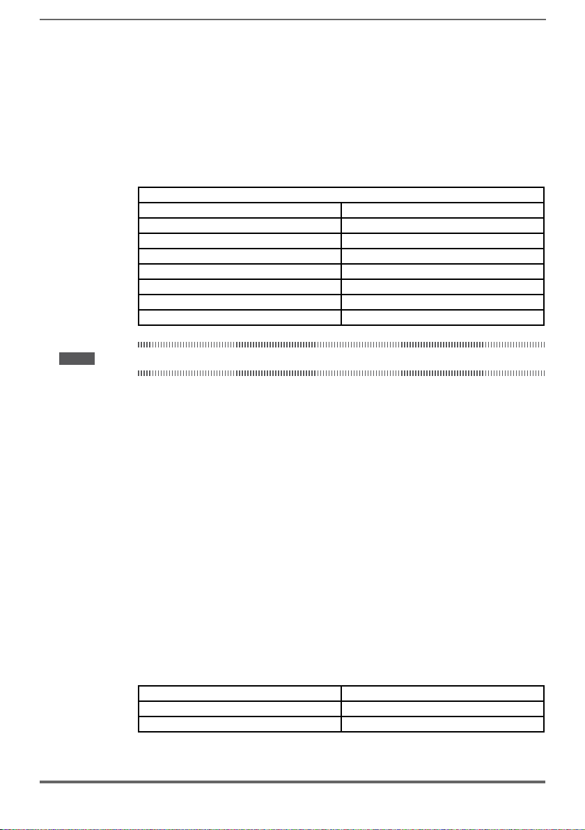
Short circuit ratings
AFE200 must be connected to a grid capable of supplying a symmetrical shortcircuit power of less than or equal to “xxxx A rms.
The values of the “xxxx” A rms short-circuit current, in accordance with UL requirements (UL 508 c), for each power rating (AFE output in the manual) are shown in
the table below.
Short current rating
AFE output (kW) SCCR ( A ) up to 600Vac
1,1...37,3 5000
39....149 10000
150....398 18000
299.....447 30000
448-671 42000
672-1193 85000
Note! Drive will be protected by semiconductor Fuse type as specified in the instruction manual.
Branch circuit protection
In order to protect AFE against over-current use fuses specied in par. 11.1.
Environmental condition
The AFE has to be considered “Open type equipment”. Max surrounding air temperature equal to 40°C. Pollution degree 2.
≥ 1194 100000 ... 200000
Wiring of the input and output power terminals
Use UL listed cables rated at 75°C and round crimping terminals. Crimp terminals
with tool recommended by terminal manufacturer.
Field wiring terminals shall be used with the tightening torque specied in par.
5.1.1.
Over-voltage control
In compliance with CSA-requirements Overvoltage at mains terminal is achieved
installing an overvoltage protection device as for :
Type OVR 1N 15 320 from ABB or similar.
Minimum time required for safe DC-link voltage
Before removing AFE cover in order to access internal parts, after mains disconnection wait for time as follow :
Drive size Safe time ( sec )
size 3.....5 300
size 6...7 and Parallels 300
AFE200 • Instruction Manual 9
Page 10

2 - Introduction to the product
M
E
C
Exp-Sync-ADV
SMPS and
power interface
+
Control signals
Exp-Enc-ADV
SMPS and
power interface
C+
Encoder signals
Control board Control board
AFE200 ADV200-DC
C (+)D (-)
AFE200 is the series of AC/DC Active Front End (AFE) regenerative, DC Bus
power supply units
With a powerful 32-bit technology platform and reliable IGBT power stage the
AFE200 offers signicant advantages for single or multi-inverter automation systems powered by a common DC bus.
AFE200 is intended to power the ADV200..-DC fed family of AC inverters, either
single module or multi-modules with their DC buses tied in parallel.
It may also be used to supply ADV200-...-IT series intended to be powered from a
DC input.
About use with standard products (i.e. ADV200...-4 or -6) or other brand products.
AC fed inverters may utilize input lter capacitors that exist from the input diode bridge
Caution
Note! In order to work properly, an external LCL type line input filter and precharge kit is needed.
LCL filters must be chosen based on the overload required for the AFE: Heavy Duty or Low Duty.
to ground. These capacitors are subject to failure if the product is powered via the DC
bus input.
In this scenario, the input lter capacitors should be removed before powering up the
unit from an AFE...
For GEFRAN legacy or AC fed units, please consult the factory.
For Other Brand products, consult the manufacturer of that product.
Connection with Precharge Kit and LCL Filter
PRECHARGE SECTION
K1M
D
C
K2M
LCL Input Filter
LC-AFE
LR3-AFE
AC Main
Supply
EMI Filter
Reduced operating costs
The AFE200 achieves considerable savings in terms of power consumption
and the relative costs. The kinetic energy of the inertia of the loads transformed
into electric energy by the AFE200 is sent back to the mains supply during
10 AFE200 • Instruction Manual
Page 11

braking. In conventional resistor braking systems this power is dissipated in the
form of heat. The excess energy can be used to supply other equipment.
Production of Clean Power
The regeneration technology of the AFE200 uses advanced control algorithms to
provide clean power. A signicant reduction in harmonic distortion (less than
3% considering an AC main supply with THD voltage lower than 2%) and the input
current in phase with the input voltage enable unitary power factor operation,
for additional energy saving and system efciency.
Enhanced control dynamics
Used in single or multi-inverter solutions powered by a common DC bus the
AFE200 also guarantees high-level control dynamics in AFE and energy regen-
eration conditions, which would be impossible with electric braking solutions.
Control and monitoring performed on the DC-link also prevent the risk of undesirable stoppages during power transients and make the AFE200 a reliable solution
for use in networks with high voltage uctuation levels.
Typical applications
The AFE200 is ideal for applications that require management of high-inertia loads
or with high operating dynamics, such as: test benches, industrial lifting applications, centrifuges, mixers, ventilation systems, renewable energy systems, rolling
systems, high-power servo systems, etc.
The economic benets of using the AFE200 in applications such as these are not
of secondary importance.
AFE200 • Instruction Manual 11
Page 12
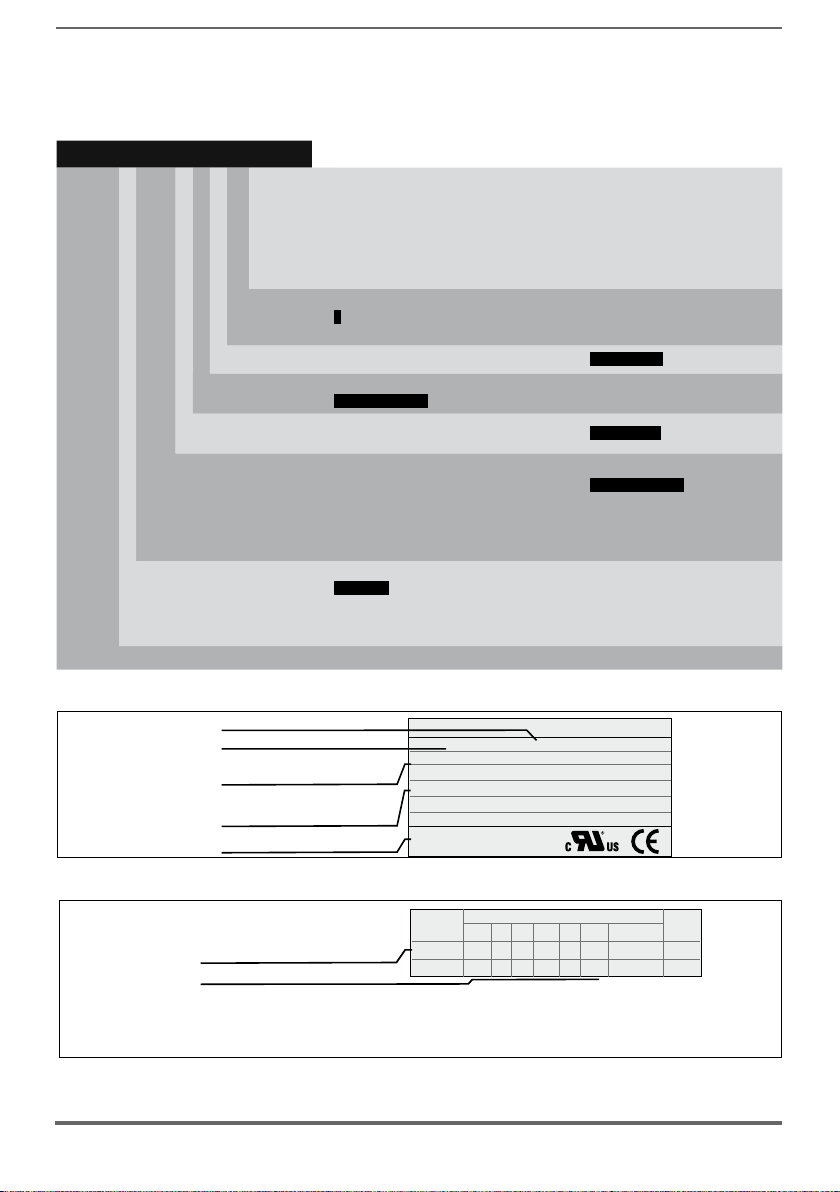
2.1 Product type designation
Firmware HW release S/N 09012345 Prod.
Release
DFPRSBUSW.CFG
CONF
0.8.0 A -.G -.I 10.10.10 A1
Power
Regulation
Safety
Braking unit
Software
revision
Product
configuration
Cards revision
Firmware revision
The main technical characteristic of the AFE200 are showed in the product code
and in the nameplate.
AFE200 3 200 -K X X -4 -XX YY
Parallel version only:
XX : MS = MASTER
SL = SLAVE with MS/SL cable 1m length
SL2 = SLAVE with MS/SL cable 2m length
Rated voltage (factory setting):
4 = 400 Vac, 50 Hz
6 = 500...690 Vac
Software:
Braking unit:
X = not included
Keypad:
X = non included
Power, in kW:
200 = 22.0 kW
450 = 45.0 kW
900 = 90.0 kW
1100 = 110.0 kW
1320 = 132.0 kW
1600 = 160.0 kW
Mechanical sizes:
3 = size 3
4 = size 4
5 = size 5
YY : 04 = 400.0 kW
05 = 500.0 kW
06 = 630.0 kW
07 = 710.0 kW
09 = 900.0 kW
10 = 1 MW
14 = 1.35 MW
17 = 1.65 MW
X = standard
B = included
K = included
2000 = 200.0 kW
2500 = 250.0 kW
3150 = 315.0 kW
3550 = 355.0 kW
6 = size 6
7 = size 7
Active Front End Regenerative Power Supply Unit
Identication Nameplate
Serial number
Model
Input (mains supply)
Output (Output voltage, power,
current, CT and VT overloads)
Approvals
Type: AFE200-3220 -KXX-4 S/N: 09012345
Inp: 400Vac -15% ÷ 500 Vac +5% 50/60 Hz 3ph
40A@400Vac 36A@480Vac
Out : 650Vdc-780Vdc
28kW 43A @650Vdc 39A @780Vdc Ovld.150% -60s
42kW 64A @650Vdc 57A @780Vdc Ovld.110% -60s
Firmware & cards revision level nameplate
The choice of AFE200 depends on the power rating of the inverters connected to
the DC-link.
12 AFE200 • Instruction Manual
Gefran S.p.Avia G.Carducci, 24
I-21040-Gerenzano, VA
Page 13
The rated output current of the AFE200 must be higher or equal to the sum of the
power ratings of the AFE200 connected to the DC-link. For further information
please see Appendix 1.
(*) The power rating in kW shown on the product data plate refers to that of the equivalent ADV200-DC.
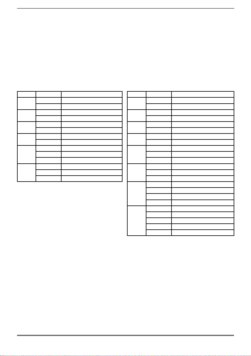
2.1.1 Parallel congurations
A parallel connection of several units basically consists of one MASTER unit and
one or more SLAVE units.
When placing your order please give the code number of the master and slave
and number of these:
Power code Description (Designation) Power code Description (Designation)
400kW
500kW
630kW
710kW
900kW
1MW
S9AF21M AFE200-72000-KXX-4-MS 04
S9AF21S AFE200-72000-XXX-4-SL S9AF51S AFE200-72000-XXX-6-SL
S9AF22M AFE200-72500-KXX-4-MS 05
S9AF22S AFE200-72500-XXX-4-SL S9AF52S AFE200-72500-XXX-6-SL
S9AF23M AFE200-73150-KXX-4-MS 06
S9AF23S AFE200-73150-XXX-4-SL S9AF53S AFE200-73150-XXX-6-SL
S9AF24M AFE200-73550-KXX-4-MS 07
S9AF24S AFE200-73550-XXX-4-SL S9AF54S AFE200-73550-XXX-6-SL
S9AF231 AFE200-73150-KXX-4-MS 09
S9AF23S AFE200-73150-XXX-4-SL S9AF53S AFE200-73150-XXX-6-SL
S9AF23S AFE200-73150-XXX-4-SL S9AF53S AFE200-73150-XXX-6-SL
S9AF241 AFE200-73550-KXX-4-MS 10
S9AF24S AFE200-73550-XXX-4-SL S9AF54S AFE200-73550-XXX-6-SL
S9AF24S AFE200-73550-XXX-4-SL S9AF54S AFE200-73550-XXX-6-SL
400kW
500kW
630kW
710kW
900kW
1MW
1.35MW
1.65MW
S9AF51M AFE200-72000-KXX-6-MS 04
S9AF52M AFE200-72500-KXX-6-MS 05
S9AF53M AFE200-73150-KXX-6-MS 06
S9AF54M AFE200-73550-KXX-6-MS 07
S9AF53M1 AFE200-73150-KXX-6-MS 09
S9AF54M1 AFE200-73550-KXX-6-MS 10
S9AF54M4 AFE200-73550-KXX-6-MS 14
S9AF54S AFE200-73550-XXX-6-SL
S9AF54S AFE200-73550-XXX-6-SL
S9AF54S2 AFE200-73550-XXX-6-SL2
S9AF54M5 AFE200-73550-KXX-6-MS 17
S9AF54S AFE200-73550-XXX-6-SL
S9AF54S AFE200-73550-XXX-6-SL
S9AF54S2 AFE200-73550-XXX-6-SL2
S9AF54S2 AFE200-73550-XXX-6-SL2
AFE200 • Instruction Manual 13
Page 14
3 - Transport and storage
Caution
Correct transport, storage, erection and mounting, as well as careful operation and
maintenance are essential for proper and safe operation of the equipment.
Protect the AFE200 against physical shocks and vibration during transport and storage.
Also be sure to protect it against water (rainfall) and excessive temperatures.
Le bon accomplissement des opérations de transport, de stockage, d’installation et de montage, ainsi que l’exploitation et l’entretien minutieux, sont essentiels pour garantir à l’appareil
un fonctionnement adéquat et sûr.
If the AFE have been stored for longer than two years, the operation of the DC link
capacitors may be impaired and must be “reformed”. Before commissioning devices
that have been stored for long periods, connect them to a power supply for two hours
with no load connected in order to regenerate the capacitors, (the input voltage has to
be applied without enabling the AFE).
En cas de stockage des AFE pendant plus de deux ans, il est conseillé de contrôler l’état
des condensateurs CC avant d’en effectuer le branchement. Avant la mise en service des
appareils, ayant été stockés pendant long temps, il faut alimenter variateurs à vide pendant
deux heures, pour régénérer les condensateurs : appliquer une tension d’alimentation sans
actionner le AFE.
3.1 General
A high degree of care is taken in packing the AFE200 product and preparing them
for delivery. They should only be transported with suitable transport equipment
(see weight data). Observe the instructions printed on the packaging. This also applieswhen the device is unpacked and installed in the control cabinet.
Upon delivery, check the following:
- the packaging for any external damage
- whether the delivery note matches your order.
Open the packaging with suitable tools. Check whether:
- any parts were damaged during transport
- the device type corresponds to your order
In the event of any damage or of an incomplete or incorrect delivery please notify
the responsible sales ofces immediately. The devices should only be stored in
dry rooms within the specied temperature ranges .
Note! A certain degree of moisture condensation is permissible if this arises from changes in temperature.
This does not, however, apply when the devices are in operation. Always ensure that there is no
moisture condensation in devices that are connected to the power supply!
14 AFE200 • Instruction Manual
Page 15

3.2 Permissible Environmental Conditions
Temperature
storage �������������������� -25…+55°C (-13…+131°F), class 1K4 per EN50178
transport ������������������� -25…+70°C (-13…+158°F), class 2K3 per EN50178
Air humidity
storage �������������������� 5% to 95 %, 1 g/m3 to 29 g/m3 (class 1K3 as per EN50178)
transport ������������������� 95 % (3), 60 g/m3 (4)
A light condensation of moisture may occur for a short time occasionally if the device is not in operation
(class 2K3 as per EN50178)
Air pressure:
storage �������������������� [kPa] 86 to 106 (class 1K4 as per EN50178)
transport ������������������� [kPa] 70 to 106 (class 2K3 as per EN50178)
(3) Greatest relative air humidity occurs with the temperature @ 40°C (104°F) or if the temperature of the
device is brought suddenly from -25 ...+30°C (-13°...+86°F).
(4) Greatest absolute air humidity if the device is brought suddenly from 70...15°C (158°...59°F).
-20…+55°C (-4…+131°F), for devices with keypad
-20…+60°C (-4…+140°F), for devices with keypad
AFE200 • Instruction Manual 15
Page 16
4 - Mechanical installation
The AFE must be mounted on a wall that is constructed of heat resistant material.
While the AFE is operating, the temperature of the AFE’s cooling ns can rise to a
temperature of 158° F (70°C).
Le AFE doit être monté sur un mur construit avec des matériaux résistants à la chaleur.
Pendant le fonctionnement du AFE, la température des ailettes du dissipateur thermique peut
arriver à 70°C (158° F).
Because the ambient temperature greatly affects AFE life and reliability, do not install
the AFE in any location that exceeds the allowable temperature.
Étant donné que la température ambiante inue sur la vie et la abilité du AFE, on ne devrait
pasinstaller le AFE dans des places ou la temperature permise est dépassée.
Be sure to remove the desicant dryer packet(s) when unpacking the AFE. (If not
removed these packets may become lodged in the fan or air passages and cause the
AFE to overheat).
Lors du déballage du AFE, retirer le sachet déshydraté. (Si celui-ci n’est pas retiré, il empêche
la ventilation et provoque une surchauffe du AFE).
Protect the device from impermissible environmental conditions (temperature, humidity,
shock etc.).
Protéger l’appareil contre des effets extérieurs non permis (température, humidité, chocs etc.).
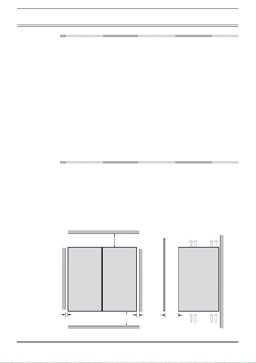
4.1 Inclination and mounting clearance
The AFE200 must be mounted in such a way that the free ow of air is ensured
see paragraph 10.7 Cooling.
Maximum angle of inclination �����������30° (referred to vertical position)
Minimum top and bottom distance �������150 mm (≥AFE200-71600 = 400mm)
Minimum free space to the front ���������25 mm
Minimum distance between drives �������none
Minimum distance to the side with the cabinet
≥
150 mm[6"]
400 mm[15.75" ] (ADV 7...)
≥
≥
10 mm [ 0.4" ]≥
150 mm[6"]
≥400 mm[15.75" ] (ADV 7...)
10 mm
16 AFE200 • Instruction Manual
25 mm [ 0.98” ]≥10 mm [ 0.4" ]≥
Page 17
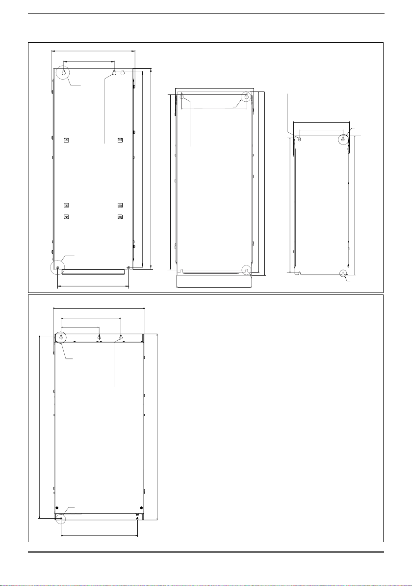
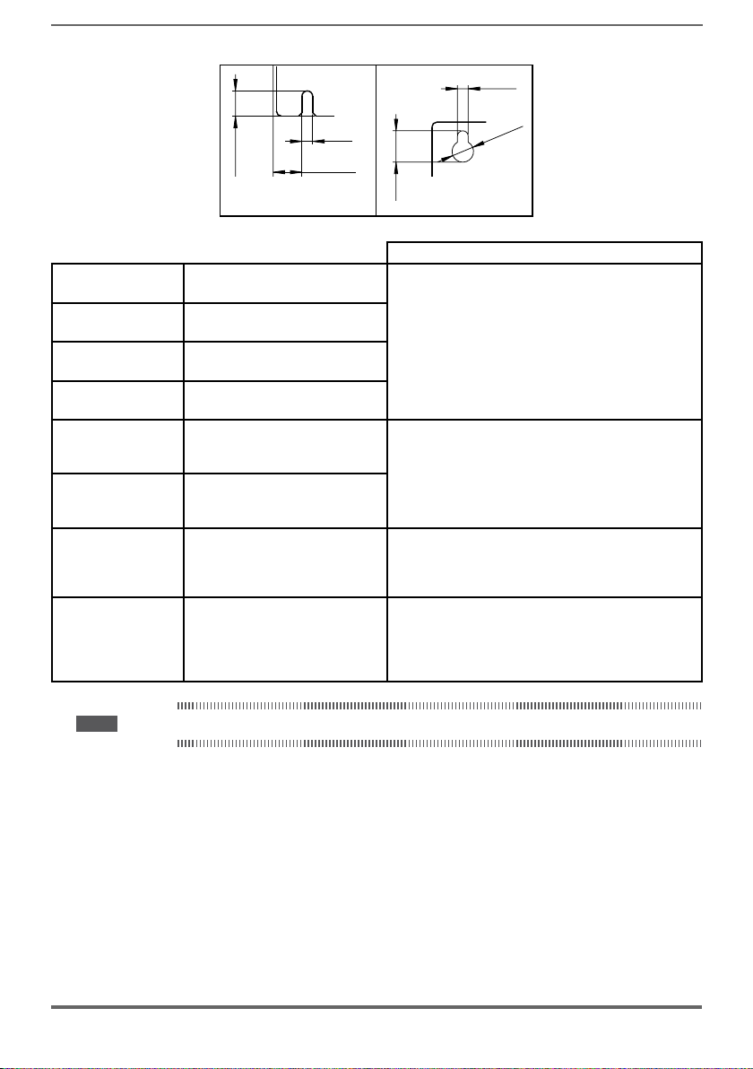
4.2 Fastening positions
311 [12.24”]
190 [7.48”]
Fissaggioamuro
Wall mounting
(B)
(A)
175 [6.89”]
(B)
Taglia 5
Size 5
265 [10.43”]
421 [16.57”]
275 [10.83”]
No. 4 screw 6MA
268 [10.55”]
(A)
220 [8.66”]
187.6 [7.4”]
150 [5.91”]
No. 4 screw 5MA
No. 4 screw 6MA
730.4 [28.76”]
748 [29.45”]
595 [23.43”]
612 [24.09”]
616 [24.25”]
500.1 [19.7”]
Taglia 4
Size 4
267 [10.51”]
(B)
Taglia 3
Size 3
(A)
517 [20.35”]
(B)
Fissaggioamuro
Wall mounting
No. 5 screw 6MA
836 [32.91”]
853 [33.58”]
Taglia 6
Size 6
(A)
350 [13.78”]
AFE200 • Instruction Manual 17
Page 18
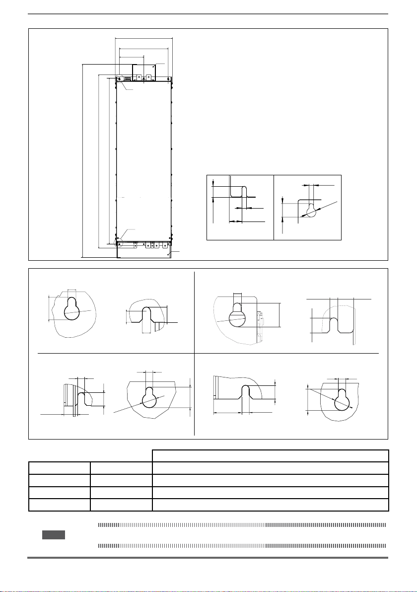
417 [16.42”]
355.6 [140”]
177.8 [7.00”]
(B)
(*)
Fissaggioamuro
Wall mounting
[0.59”]
15
12.75 [0.50”]
5.5 [0.21”]
[55.4”]
1407
6.5 [0.26”]
10
Ø
[47.62”]
[49.76”]
1264
1209.5
Taglie 1-2-3
Sizes 1-2-3
[0.39”]
Taglia 5
Size 5
[0.47”]
12
13
Ø
Taglia 7
Size 7
(A)
[0.29”]
7.25
5.5 [0.21”]
[0.51”]
(*) Protezione in policarbonato trasparente
(*) Protective trasparent policarbonate
6.5
[0.26”]
(B)
6.5 [0.26”]
[0.47”]
12
[0.75”]
19
Ø 13
[0.51”]
12.5 [0.49”]
(B)(A)
6.5 [0.26”]
Ø
13
[0.51”]
(B)(A)
6.5
[0.26”]
[0.6”]
[0.51”]
24.95 [0.98”]
6.5 [0.26”]
(A)
17.45
[0.69”]
6.5 [0.26”]
[0.47”]
12
[0.75”]
19
19
[0.75”]
Taglia 4
Size 4
Taglia 6
Size 6
15.25
(*)
[0.44”]
[0.75”]
19
13
Ø
11.25
(B)(A)
[0.26”]
6.5
(B)(A)
Recommended screws for fastening
Size 3 (AFE 3...) 4 x M5 x 12 mm screws + Grover (spring-lock) washer + Flat washer
Size 4 (AFE 4...) Size 5 (AFE 5...) 4 x M6 x 16 mm screws + Grover (spring-lock) washer + Flat washer
Size 6 (AFE 6...) 5 x M6 x 16 mm screws + Grover (spring-lock) washer + Flat washer
Size 7 (AFE 7...) 6 x M6 x 16 mm screws + Grover (spring-lock) washer + Flat washer
Note! Other dimensions see chapter 10.8 Weight and dimensions.
18 AFE200 • Instruction Manual
Page 19
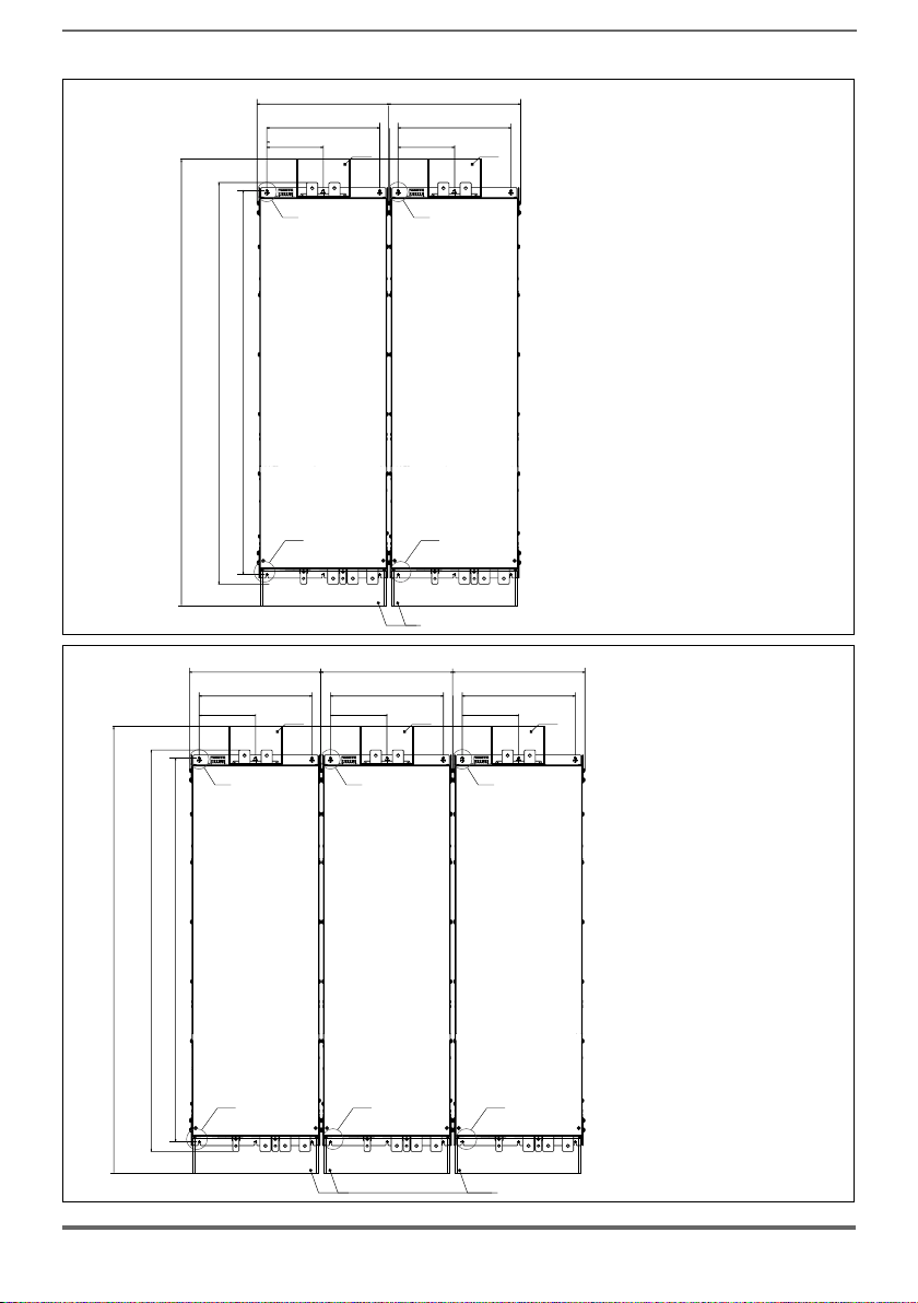
[55.4”]
1407
[47.62”]
[49.76”]
1264
1209.5
417 [16.42”]
355.6
177.8 [7.00”]
(B)
[140”]
177.8 [7.00”]
(*) (*)
417 [16.42”]
355.6
[140”]
(B)
Fissaggioamuro
Wall mounting
400 ... 710 kW
[55.4”]
1407
[47.62”]
[49.76”]
1264
1209.5
417 [16.42”]
355.6 [140”]
177.8 [7.00”]
(B)
(A)
(A)
(*)
417 [16.42”]
355.6 [140”]
177.8 [7.00”]
(B)
(A)
(A)
(*) Protezione in policarbonato trasparente
(*)
(*) Protective trasparent policarbonate
417 [16.42”]
355.6 [140”]
(*)
177.8 [7.00”]
(*)
Fissaggioamuro
Wall mounting
(B)
900 ... 1000 kW
(A)
(*) Protezione in policarbonato trasparente
(*) (*)
AFE200 • Instruction Manual 19
(*) Protective trasparent policarbonate
Page 20
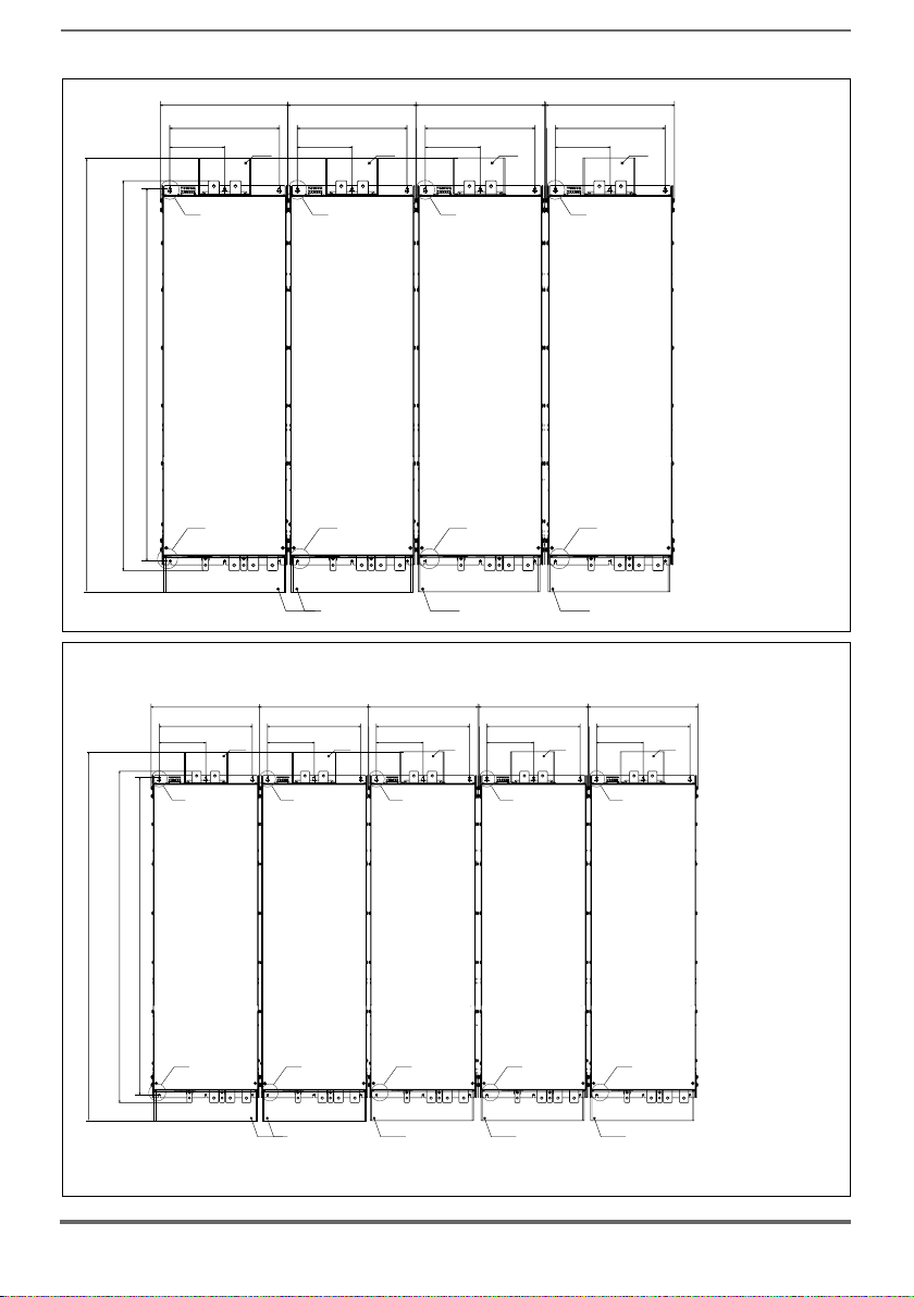
[55.4”]
1407
[47.62”]
[49.76”]
1264
1209.5
417 [16.42”]
355.6
177.8 [7.00”]
(B)
[140”]
(*)
417 [16.42”]
355.6
177.8 [7.00”]
(B)
[140”]
(*)
417 [16.42”]
355.6
177.8 [7.00”]
(B)
[140”]
417 [16.42”]
355.6
[140”]
177.8 [7.00”]
(*)
(*)
Fissaggio a muro
Wall mounting
(B)
1350 kW
[55.4”]
1407
[49.76”]
1264
[47.62”]
1209.5
(A)
417 [16.42”]
355.6 [140”]
177.8 [7.00”]
(B)
(A)
(A)
(*)
417 [16.42”]
355.6 [140”]
177.8 [7.00”]
(*) (*)
(B)
(A)
(*)
417 [16.42”]
355.6 [140”]
177.8 [7.00”]
(B)
(A)
(*)
(A)
(*)
417 [16.42”]
355.6 [140”]
177.8 [7.00”]
(*)
(A)
(*)
(*) Protezione in policarbonato trasparente
(*) Protective trasparent policarbonate
417 [16.42”]
355.6 [140”]
177.8 [7.00”]
(*)
(*)
Fissaggio a muro
Wall mounting
(B)
(B)
1650 kW
(A)
(*)
(A)
(*) Protezione in policarbonato trasparente
(*)
(*) Protective trasparent policarbonate
20 AFE200 • Instruction Manual
Page 21
6.5
[0.75”]
[0.26”]
400kW
500kW
630kW
710kW
900kW
1MW
1.35 MW
1.65 MW
15.25
[0.6”]
17.45
[0.69”]
(A)
AFE200-72000-KXX-.-MS 04
AFE200-72000-XXX-.-SL
AFE200-72500-KXX-.-MS 05
AFE200-72500-XXX-.-SL
AFE200-73150-KXX-./..-MS 06
AFE200-73150-XXX-./..-SL
AFE200-73550-KXX-./..-MS 07
AFE200-73550-XXX-./..-SL
AFE200-73150-KXX-./..-MS 09
AFE200-73150-XXX-./..-SL
AFE200-73150-XXX-./..-SL
AFE200-73550-KXX-./..-MS 10
AFE200-73550-XXX-./..-SL
AFE200-73550-XXX-./..-SL
AFE200-73550-KXX-./..-MS 14
AFE200-73550-XXX-./..-SL2
AFE200-73550-XXX-./..-SL
AFE200-73550-XXX-./..-SL
AFE200-73550-KXX-./..-MS 17
AFE200-73550-XXX-./..-SL2
AFE200-73550-XXX-./..-SL2
AFE200-73550-XXX-./..-SL
AFE200-73550-XXX-./..-SL
6.5
[0.26”]
Ø 13
[0.51”]
19
Recommended screws for fastening
12 x M6 x 16 mm screws + Grover (spring-lock) washer + Flat
washer
18 x M6 x 16 mm screws + Grover (spring-lock) washer + Flat
washer
24 x M6 x 16 mm screws + Grover (spring-lock) washer + Flat
washer
30 x M6 x 16 mm screws + Grover (spring-lock) washer + Flat
washer
(B)
Note! Other dimensions see chapter 10.8 Weight and dimensions.
AFE200 • Instruction Manual 21
Page 22
5 - Wiring Procedure
Caution
AFE are electrical apparatus for use in industrial installations. Parts of the AFE are
energized during operation. The electrical installation and the opening of the device
should therefore only be carried out by qualied personnel. Improper installation of
motors or AFE may therefore cause the failure of the device as well as serious injury
to persons or material damage. Drive is not equipped with motor overspeed protection
logic other than that controlled by software. Follow the instructions given in this manual
and observe the local and national safety regulations applicable.
Les AFE à fréquence variable sont des dispositifs électriques utilisés dans des installations industriels. Une partie des AFE sont sous tension pendant l’operation. L’installation électrique et
l’ouverture des AFE devrait être executé uniquement par du personel qualié. De mauvaises
installations de moteurs ou de AFE peuvent provoquer des dommages materiels ou blesser
des personnes. On doit suivir les instructions donneés dans ce manuel et observer les régles
nationales de sécurité.
Replace all covers before applying power to the AFE. Failure to do so may result in
death or serious injury.
Remettre tous les capots avant de mettre sous tension le AFE. Des erreurs peuvent provoquer de sérieux accidents ou même la mort.
The AFE must always be grounded. If the AFE is not connected correctly to ground,
extremely hazardous conditions may be generated that may result in death or serious
Warning!
injury.
Le AFE doit toujours être raccordé au système de mise à la terre. Un mauvais raccorde-
ment du AFE au système de mise à la terre peut se traduire par des conditions extrêmement
dangereuses susceptibles d’entraîner le décès ou de graves lésions corporelles.
Never open the device or covers while the AC Input power supply is switched on. Minimum
time to wait before working on the terminals or inside the device is listed in section "10.7
Voltage level of AFE200 for safe operations" .
Ne jamais ouvrir l’appareil lorsqu’il est suns tension. Le temps minimum d’attente avant de pouvoir travailler sur les bornes ou bien à l’intérieur de l’appareil est indiqué dans la section 10.7.
Do not touch or damage any components when handling the device. The changing of
the isolation gaps or the removing of the isolation and covers is not permissible.
Manipuler l’appareil de façon à ne pas toucher ou endommager des parties. Il n’est pas
permis de changer les distances d’isolement ou bien d’enlever des matériaux isolants ou des
capots.
Do not connect power supply voltage that exceeds the standard specication voltage
uctuation permissible. If excessive voltage is applied to the Drive, damage to the
internal components will result.
Ne pas raccorder de tension d’alimentation dépassant la uctuation de tension permise par
les normes. Dans le cas d’ une alimentation en tension excessive, des composants internes
peuvent être endommagés.
Operation with Residual Current Device
If an RCD (also referred to as ELCB or RCCB) is tted, the inverters will operate without
nuisance tripping, provided that:
- a type B RCD is used.
- the trip limit of the RCD is 300mA.
- the neutral of the supply is grounded (TT or TN systems)
22 AFE200 • Instruction Manual
Page 23
- only one AFE200 is supplied from each RCD.
- the output cables are less than 50m (screened) or 100m (unscreened).
RCD: Residual Current Device
RCCB: Residual Current Circuit Breaker
ELCB: Earth Leakage Circuit Breaker
Note: The residual current operated circuit-breakers used must provide protection
against direct-current components in the fault current and must be suitable for
briey suppressing power pulse current peaks. It is recommended to protect the
AFE200 by fuse separately.
The regulations of the individual country (e.g. VDE regulations in Germany) and
the regional power suppliers must be observed!
Fonctionnement avec un dispositif de courant résiduel
En cas d’installation d’un RCD – dispositif de courant résiduel – (également dénommé RCCB
ou ELCB), les onduleurs fonctionneront sans faux arrêt à condition que :
- le RCD utilisé soit de type B
- le seuil de déclenchement du RCD soit xé à 300 mA
- le neutre du bloc d’alimentation soit mis à la terre (systèmes TT ou TN)
- chaque RCD n’alimente qu’un seul onduleur
- la longueur des câbles de sortie soit inférieure à 50 m (blindés) ou 100 m (non blindés)
RCD: Dispositif de courant résiduel
RCCB: Disjoncteur à courant résiduel
ELCB: Disjoncteur contre fuite à la terre
Remarque : Les RCD utilisés doivent assurer la protection contre les composants à courant
Respecter la réglementation des pays concernés (par exemple, les normes VDR
continu présents dans le courant de défaut et doivent être capables de supprimer des crêtes de courant en peu de temps. Il est recommandé de protéger
séparément l’AFE200 de fusibles.
en Allemagne) et des fournisseurs locaux d’énergie électrique.
Functioning of the AFE without a ground connection is not permitted.
Défense de faire fonctionner le AFE sans qu’il y ait eu raccordement de mise à la terre préa-
Caution
lable
The grounding connector shall be sized in accordance with the NEC or Canadian Electrical Code. The connection shall be made by a UL listed or CSA certied closed-loop
terminal connector sized for the wire gauge involved. The connector is to be xed using
the crimp tool specied by the connector manufacturer.
Le raccordement devrait être fait par un connecteur certié et mentionné à boucle fermé par
lesnormes CSA et UL et dimensionné pour l’épaisseur du cable correspondant. Le connecteur
doit êtrexé a l’aide d’un instrument de serrage specié par le producteur du connecteur.
Do not perform a megger test between the AFE terminals or on the control circuit
terminals.
Ne pas exécuter un test megger entre les bornes du AFE ou entre les bornes du circuit de
contrôle.
The electrical commissioning should only be carried out by qualied personnel, who
are also responsible for the provision of a suitable ground connection and a protected
power supply feeder in accordance with the local and national regulations.
La mise en service électrique doit être effectuée par un personnel qualié. Ce dernier est
responsable del’existence d’une connexion de terre adéquate et d’une protection des câbles
d’alimentation selon les prescriptions locales et nationales.
If the AFE have been stored for longer than two years, the operation of the DC link
AFE200 • Instruction Manual 23
Page 24
capacitors may be impaired and must be “reformed”. Before commissioning devices
PE
PEN
PE
PE
that have been stored for long periods, connect them to a power supply for two hours
with no load connected in order to regenerate the capacitors (the input voltage has to
be applied without enabling the AFE).
En cas de stockage des variateurs pendant plus de deux ans, il est conseillé de contrôler
l’état des condensateurs CC avant d’en effectuer le branchement. Avant la mise en service
des appareils, ayant été stockés pendant long temps, il faut alimenter variateurs à vide pen-
dant deux heures, pour régénérer les condensateurs : appliquer une tension d’alimentation
sans actionner le AFE.
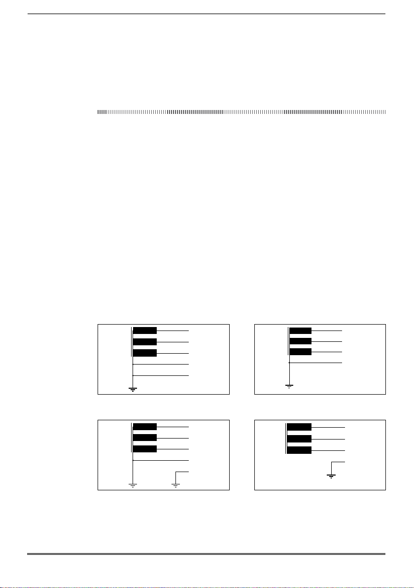
Type of networks
AFE are designed to be powered from standard three phase lines that are electrically symmetrical with respect to ground (TN or TT network). It is possible the use
with IT network. In case of use of networks at 690Vac, all AFE200-6 sizes with the
use of standard lters (EMI-FN3359HV series) can be utilized.
For the series 400/480V (AFE200-4), only the size 4450 and 5900 must be requested specically for use for IT networks (AFE200-4-IT series).
All AFE200-4 requires the use of special EMC lters for IT networks (on request).
Power supply networks
Based on the grounding method, the IEC 60634-1 describes three main types of
grounding for power supply networks: TN, TT and IT systems.
In particular, the IT system has all the active parts insulated from earth or a point
connected to ground through an impedance. The earths of the system are connected separately or collectively to the system ground.
The following gures show these different systems.
TN-S supply lines TN-C supply lines
L1
L2
L3
N
TT supply lines IT supply lines
L1
L2
L3
N
24 AFE200 • Instruction Manual
L1
L2
L3
L1
L2
L3
Page 25
5.1 Power section
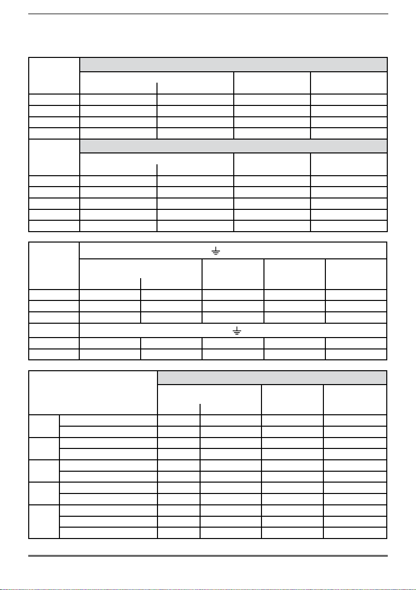
5.1.1 Cable Cross Section
Terminals: C - D - U - V - W
Sizes
AFE200-...-4
3220 16 6 14 1.5 ... 1.7
4450 35 2 18 2.4 ... 4.5
5900 95 4/0 23 14
61320 240 500 40 40
Sizes
AFE200-...-4
71600 2 x 100 2 x AWG 4/0 M10 50
72000 2 x 100 2 x AWG 4/0 M10 50
72500 2 x 150 2 x kcmil 300 M10 50
73150 2 x 185 2 x kcmil 350 M10 50
73550 2 x 185 2 x kcmil 350 M10 50
Maximum Cable Cross Section (flexible conductor) Recommended stripping Tightening torque (min)
2
(mm
) AWG (mm) (Nm)
Bars: C - D - U - V - W
Recommended cable cross-section Lock screw diameter Tightening torque (min)
2
) AWG / kcmil (mm) (Nm)
(mm
Sizes
AFE200-...-4
Terminals:
Cable Cross Section
2
) AWG / kcmil (mm) (Nm)
(mm
on mechanical cabinet
Lock screw
diameter
Recommended
terminal
Tightening torque
3220 ... 4450 16 AWG 6 M6 Eyelet - Spade 10
5900 50 AWG 1/0 M6 Eyelet - Spade 10
61320 120 250 kcmil M8 Eyelet - Spade 24
Terminals:
on bars
71600 ... 72500 150 300 kcmil M10 Eyelet 50
73150 - 73550 185 350 kcmil M10 Eyelet 50
Bars: C - D - U - V - W
400kW
500kW
630kW
710kW
900kW
Sizes
AFE200-...-4
Recommended cable cross-section
2
(mm
) AWG / kcmil (mm) (Nm)
72000-KXX-4-MS 04 2 x 100 2 x AWG 4/0 M10
72000-XXX-4-SL 2 x 100 2 x AWG 4/0 M10 (U,V,W=M12) 50 (M10) / 75 (M12)
72500-KXX-4-MS 05 2 x 150 2 x kcmil 300 M10
72500-XXX-4-SL 2 x 150 2 x kcmil 300 M10 (U,V,W=M12) 50 (M10) / 75 (M12)
73150-KXX-4-MS 06 2 x 185 2 x kcmil 350 M10
73150-XXX-4-SL 2 x 185 2 x kcmil 350 M10 (U,V,W=M12) 50 (M10) / 75 (M12)
73550-KXX-4-MS 07 2 x 185 2 x kcmil 350 M10
73550-XXX-4-SL 2 x 185 2 x kcmil 350 M10 (U,V,W=M12) 50 (M10) / 75 (M12)
73150-KXX-4-MS 09 2 x 185 2 x kcmil 350 M10
73150-XXX-4-SL 2 x 185 2 x kcmil 350 M10 (U,V,W=M12) 50 (M10) / 75 (M12)
Lock screw
diameter
(U,V,W=M12) 50 (M10) / 75 (M12)
(U,V,W=M12) 50 (M10) / 75 (M12)
(U,V,W=M12) 50 (M10) / 75 (M12)
(U,V,W=M12) 50 (M10) / 75 (M12)
(U,V,W=M12) 50 (M10) / 75 (M12)
Tightening torque
(min)
73150-XXX-4-SL 2 x 185 2 x kcmil 350 M10 (U,V,W=M12) 50 (M10) / 75 (M12)
AFE200 • Instruction Manual 25
Page 26
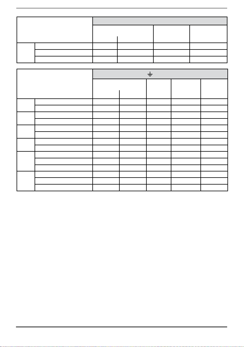
1MW
Bars: C - D - U - V - W
Sizes
AFE200-...-4
Recommended cable cross-section
2
(mm
) AWG / kcmil (mm) (Nm)
AFE200-73550-KXX-4-MS 10 2 x 185 2 x kcmil 350 M10
Lock screw
diameter
(U,V,W=M12) 50 (M10) / 75 (M12)
Tightening torque
(min)
AFE200-73550-XXX-4-SL 2 x 185 2 x kcmil 350 M10 (U,V,W=M12) 50 (M10) / 75 (M12)
AFE200-73550-XXX-4-SL 2 x 185 2 x kcmil 350 M10 (U,V,W=M12) 50 (M10) / 75 (M12)
Terminals:
Sizes
AFE200-...-4
72000-KXX-4-MS 04 150 300 kcmil M10 Eyelet 50
400kW
72000-XXX-4-SL 150 300 kcmil M10 Eyelet 50
72500-KXX-4-MS 05 150 300 kcmil M10 Eyelet 50
500kW
72500-XXX-4-SL 150 300 kcmil M10 Eyelet 50
73150-KXX-4-MS 06 185 350 kcmil M10 Eyelet 50
630kW
73150-XXX-4-SL 185 350 kcmil M10 Eyelet 50
73550-KXX-4-MS 07 185 350 kcmil M10 Eyelet 50
710kW
73550-XXX-4-SL 185 350 kcmil M10 Eyelet 50
Recommended cable
cross-section
2
) AWG / kcmil (mm) (Nm)
(mm
on mechanical cabinet
Lock screw
Recommended
diameter
73150-KXX-4-MS 09 185 350 kcmil M10 Eyelet 50
900kW
73150-XXX-4-SL 185 350 kcmil M10 Eyelet 50
73150-XXX-4-SL 185 350 kcmil M10 Eyelet 50
AFE200-73550-KXX-4-MS 10 185 350 kcmil M10 Eyelet 50
AFE200-73550-XXX-4-SL 185 350 kcmil M10 Eyelet 50
1MW
AFE200-73550-XXX-4-SL 185 350 kcmil M10 Eyelet 50
terminal
Tightening
torque (min)
26 AFE200 • Instruction Manual
Page 27
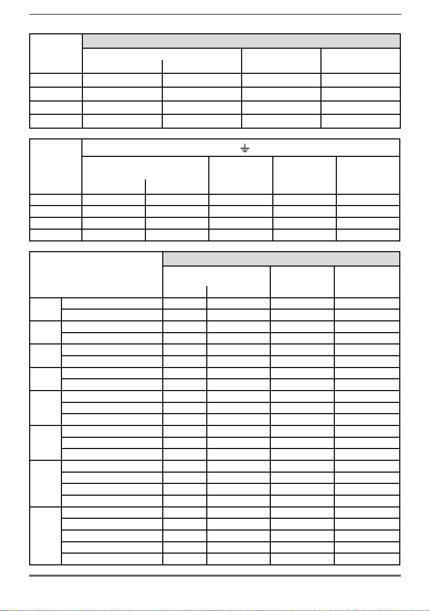
Sizes
AFE200-...-6
Recommended cable cross-section Lock screw diameter Tightening torque (min)
2
(mm
) AWG / kcmil (mm) (Nm)
71600 95 AWG 4/0 M10 50
72000 150 300 kcmil M10 50
72500 240 500 kcmil M10 50
73150 - 73550 2 x 100 2 x AWG 4/0 M10 50
Bars: C - D - U - V - W
Sizes
AFE200-...-6
Terminals:
Cable Cross Section Lock screw
2
(mm
) AWG / kcmil (mm) (Nm)
diameter
on bars
Recommended
terminal
Tightening torque
71600 50 AWG 1/0 M10 Eyelet 50
72000 75 AWG 2/0 M10 Eyelet 50
72500 120 250 kcmil M10 Eyelet 50
73150 - 73550 150 300 kcmil M10 Eyelet 50
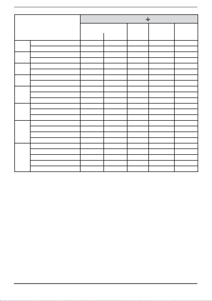
Bars: C - D - U - V - W
400kW
500kW
630kW
710kW
Sizes
AFE200-...-6
Recommended cable cross-section
2
(mm
) AWG / kcmil (mm) (Nm)
72000-KXX-6-MS 04 150 300 kcmil M10 50
72000-XXX-6-SL 150 300 kcmil M10 50
72500-KXX-6-MS 05 240 500 kcmil M10 50
72500-XXX-6-SL 240 500 kcmil M10 50
73150-KXX-6-MS 06 2 x 100 2 x AWG 4/0 M10 50
73150-XXX-6-SL 2 x 100 2 x AWG 4/0 M10 50
73550-KXX-6-MS 07 2 x 100 2 x AWG 4/0 M10 50
73550-XXX-6-SL 2 x 100 2 x AWG 4/0 M10 50
Lock screw
diameter
Tightening torque
73150-KXX-6-MS 09 2 x 100 2 x AWG 4/0 M10 50
900kW
73150-XXX-6-SL 2 x 100 2 x AWG 4/0 M10 50
73150-XXX-6-SL 2 x 100 2 x AWG 4/0 M10 50
AFE200-73550-KXX-6-MS 10 2 x 100 2 x AWG 4/0 M10 50
1MW
AFE200-73550-XXX-6-SL 2 x 100 2 x AWG 4/0 M10 50
AFE200-73550-XXX-6-SL 2 x 100 2 x AWG 4/0 M10 50
AFE200-73550-KXX-6-MS 14 2 x 100 2 x AWG 4/0 M10 50
1.35MW
AFE200-73550-XXX-6-SL2 2 x 100 2 x AWG 4/0 M10 50
AFE200-73550-XXX-6-SL 2 x 100 2 x AWG 4/0 M10 50
AFE200-73550-XXX-6-SL 2 x 100 2 x AWG 4/0 M10 50
AFE200-73550-KXX-6-MS 17 2 x 100 2 x AWG 4/0 M10 50
AFE200-73550-XXX-6-SL2 2 x 100 2 x AWG 4/0 M10 50
1.65MW
AFE200-73550-XXX-6-SL2 2 x 100 2 x AWG 4/0 M10 50
AFE200-73550-XXX-6-SL 2 x 100 2 x AWG 4/0 M10 50
AFE200-73550-XXX-6-SL 2 x 100 2 x AWG 4/0 M10 50
(min)
AFE200 • Instruction Manual 27
Page 28
400kW
500kW
630kW
710kW
900kW
1MW
1.35MW
1.65MW
Connection
Sizes
AFE200-...-6
Recommended cable
cross-section
2
) AWG / kcmil (mm) (Nm)
(mm
Lock screw
diameter
Recommended
terminal
Tightening
torque (min)
72000-KXX-6-MS 04 75 AWG 2/0 M10 Eyelet 50
72000-XXX-6-SL 75 AWG 2/0 M10 Eyelet 50
72500-KXX-6-MS 05 120 250 kcmil M10 Eyelet 50
72500-XXX-6-SL 120 250 kcmil M10 Eyelet 50
73150-KXX-6-MS 06 150 300 kcmil M10 Eyelet 50
73150-XXX-6-SL 150 300 kcmil M10 Eyelet 50
73550-KXX-6-MS 07 150 300 kcmil M10 Eyelet 50
73550-XXX-6-SL 150 300 kcmil M10 Eyelet 50
73150-KXX-6-MS 09 150 300 kcmil M10 Eyelet 50
73150-XXX-6-SL 150 300 kcmil M10 Eyelet 50
73150-XXX-6-SL 150 300 kcmil M10 Eyelet 50
AFE200-73550-KXX-6-MS 10 150 300 kcmil M10 Eyelet 50
AFE200-73550-XXX-6-SL 150 300 kcmil M10 Eyelet 50
AFE200-73550-XXX-6-SL 150 300 kcmil M10 Eyelet 50
AFE200-73550-KXX-6-MS 14 150 300 kcmil M10 Eyelet 50
AFE200-73550-XXX-6-SL2 150 300 kcmil M10 Eyelet 50
AFE200-73550-XXX-6-SL 150 300 kcmil M10 Eyelet 50
AFE200-73550-XXX-6-SL 150 300 kcmil M10 Eyelet 50
AFE200-73550-KXX-6-MS 17 150 300 kcmil M10 Eyelet 50
AFE200-73550-XXX-6-SL2 150 300 kcmil M10 Eyelet 50
AFE200-73550-XXX-6-SL2 150 300 kcmil M10 Eyelet 50
AFE200-73550-XXX-6-SL 150 300 kcmil M10 Eyelet 50
AFE200-73550-XXX-6-SL 150 300 kcmil M10 Eyelet 50
28 AFE200 • Instruction Manual
Page 29
Warning!
Attention
5.1.2 EMC guide line
In a domestic environment, this product may cause radio inference, in which case sup-
plementary mitigation measures may be required.
Dans un environnement domestique, ce produit peut causer des interférences radio, auquel
cas supplémentaire des mesures d’atténuation peuvent être nécessaires.
AFE are designed to operate in an industrial environment where a high level of
electromagnetic interference are to be expected. Proper installation practices
will ensure safe and trouble-free operation. If you encounter problems, follow the
guidelines which follow.
- Check for all equipment in the cabinet are well grounded using short, thick
grounding cable connected to a common star point or busbar. Better solution
is to use a conductive mounting plane and use that as EMC ground reference
plane.
- Flat conductors, for EMC grounding, are better than other type because they
have lower impedance at higher frequencies.
- Make sure that any control equipment (such as a PLC) connected to the
AFE200 is connected to the same EMC ground or star point as the AFE200
via a short thick link.
- Separate the control cables from the power cables as much as possible, using
separate trunking, if necessary at 90º to each other.
- Whenever possible, use screened leads for the connections to the control
circuitry.
- Ensure that the contactors in the cubicle are suppressed, either with R-C
suppressors for AC contactors or ‘ywheel’ diodes for DC contactors tted to
the coils. Varistor suppressors are also effective. This is important when the
contactors are controlled from the AFE200 relay.
- Use screened or armored cables for the U-V-W connections and ground the
screen at both ends using the cable clamps
- Use the recommended EMI lters, which are listed in section 11.3 of this
manual (conformity with EN61800-3, class C3 with 50 meters of motor cable
with a single inverter supplied by the AFE200).
- Use shielded cables in motors to ensure the correct operation of the EMI lter.
Note! For further information regarding electro-magnetic compatibility standards, according to Directive
2014/30/EC, conformity checks carried out on Gefran appliances, connection of filters and mains
inductors, shielding of cables, ground connections, etc., consult the “Electro-magnetic compatibility
guide” on the CD attached to this product.
AFE200 • Instruction Manual 29
Page 30
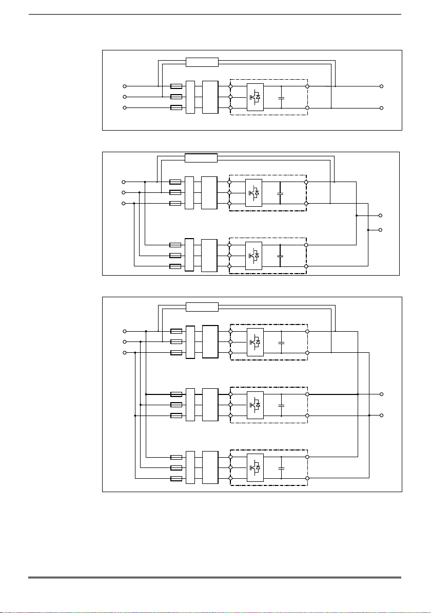
5.1.3 Block diagram power section
380-500V
500-690Vac, 3ph (AFE200-...-6)
C
D
Input
fuse
C
D
To Loads
EMI FILTER
PRECHARGE KIT
U
V
W
CDCLINK
LCL FILTER
AFE200- ...
C
D
AFE200- ...- MS..
LINE INPUT
380-500Vac, 3ph ( 4/4A)AFE200-...-
500-690Vac, 3ph (AFE200-...-6/6A)
Input
fuse
Input
fuse
AFE200- ...- SL..
C
D
To Loads
EMI FILTEREMI FILTER
PRECHARGE KIT
C
D
U
V
W
U
V
W
CDCLINK
CDCLINK
LCL FILTER
LCL FILTER
AFE200- ...- MS..
Input
fuse
Input
fuse
AFE200-- ...- SL..
C
D
C
D
Input
fuse
AFE200- ...- SL..
EMI FILTER
EMI FILTER
EMI FILTER
U
V
W
U
V
W
U
V
W
C
D
C
D
To Loads
CDCLINK
CDCLINK
CDCLINK
LINE INPUT
380-500Vac, 3ph ( 4/4A)AFE200-...-
500-690Vac, 3ph (AFE200-...-6/6A)
LCL FILTER
LCL FILTER
LCL FILTER
PRECHARGE KIT
AFE200-3220 ... 73550
LINE INPUT
ac, 3ph ( 4)AFE200-...-
AFE200 : 400kW - 710kW
AFE200 : 900kW - 1MW
30 AFE200 • Instruction Manual
Page 31

AFE200 : 1.35MW
AFE200- ...- MS..
Input
fuse
EMI FILTER
U
V
W
C
D
C
DCLINK
LINE INPUT
380-500Vac, 3ph ( 4/4A)AFE200-...-
500-690Vac, 3ph (AFE200-...-6/6A)
LCL FILTER
C
D
Input
fuse
AFE200- ...- SL..
EMI FILTER
U
V
W
CDCLINK
LCL FILTER
Input
fuse
AFE200-- ...- SL..
C
D
EMI FILTER
U
V
W
C
D
To Loads
CDCLINK
LCL FILTER
PRECHARGE KIT
C
D
Input
fuse
AFE200- ...- SL..
EMI FILTER
U
V
W
CDCLINK
LCL FILTER
AFE200- ...- MS..
Input
fuse
EMI FILTER
U
V
W
C
D
C
DCLINK
LINE INPUT
380-500Vac, 3ph ( 4/4A)AFE200-...-
500-690Vac, 3ph (AFE200-...-6/6A)
LCL FILTER
Input
fuse
AFE200-- ...- SL..
C
D
EMI FILTER
U
V
W
C
D
To Loads
CDCLINK
LCL FILTER
PRECHARGE KIT
C
D
Input
fuse
AFE200- ...- SL..
EMI FILTER
U
V
W
CDCLINK
LCL FILTER
C
D
Input
fuse
AFE200- ...- SL..
EMI FILTER
U
V
W
CDCLINK
LCL FILTER
C
D
Input
fuse
AFE200- ...- SL..
EMI FILTER
U
V
W
CDCLINK
LCL FILTER
AFE200 : 1.65MW
AFE200 • Instruction Manual 31
Page 32

5.1.4 Power line connection
UVWCDL1 L2 L3 BR1 BR2
UVW
X2X2X2
LR3-AFE
L3-1
L2-1
L1-1
X2
X2
X2
UVW
X1
X1
X2
X2
L1L2L3
X1
X1
L1L2L3
X1
X2
LC-AFE
X1
EXP-SYNC-ADV
card on SLOT2
U1 V1 W1
EMI FILTER
K2M
AFE200-3220...71600-4 (High Duty)
AFE200-3220...61320-4 (Low Duty)
AFE200-71600-6 (High Duty)
D
C
PRE CHARGE
KIT
V2
U2
3ph -VAC,380 V/ 500 50/60 Hz (AFE200-...-4)AC
3ph -V(AFE200-...-6)AC,500 V/ 690 50/60 HzAC
F11
F12
L1 L2 L3
F13
Line fuse
UVW
UVW
X2X2X2
LR3-AFE
AFE200-72000...73550-4/-6 (High Duty)
AFE200-71600...73550-4/-6 (Low Duty)
D
PRE CHARGE
C
KIT
V2
U2
3ph -VAC
380 V/ 500 50/60 Hz (AFE200-...-4)AC
3ph -V(AFE200-...-6)AC,500 V/ 690 50/60 HzAC
UVW
X1
X1
X2
X2
L1L2L3
L-AFE
X1
X1
L1L2L3
EMI FILTER
F11
F12
L1 L2 L3
,
X1
X2
X2
L3-2
X2
L2-2
X1
X2
L1-2
K2M
F13
Line fuse
X2
X2
L3-1
L3-2
X2
X2
L2-1
L2-2
C-AFE
X2
X2
L1-1
L1-2
EXP-SYNC-ADV
card on SLOT2
V1 W1
U1
Note! Recommended combination F1 fuses: see paragraph 11.1.
32 AFE200 • Instruction Manual
Page 33

5.1.5 DC output connection
-
+
Inverter 4
ADV200-DC
+
Inverter 3
ADV200-DC
DC BUS
External
fuses
-
C
D
AFE200
-
+
Inverter 1
ADV200-DC
-
+
Inverter 2
ADV200-DC
M4
M3
AFE200-3220 ... 4450
AFE200
DC output-650...780 VDC
AFE200-5900 ... 61320
BR2
DC output-650...780 VDC
CD
AFE200
AC MAINS
INPUT
Common DC bus
Common DC bus
M1
ADV200-DC
L1 L2 L3 BR1 BR2
ADV200-DC
UVWCDL1 L2 L3 BR1 BR2UVWCDL1 L2 L3 BR1 BR2
DC FUSES
C
M2
DC FUSES
D
AFE200 • Instruction Manual 33
Page 34

AFE200-71600 ... 73550
DC output - 650...780 VDC
CD
Common DC bus
DC FUSES
C
D
AFE200
AFE200 : 400kW ... 710kW
CD
DC output-650...780 VDC
AFE200-...-SL-..AFE200-...-MS-..
UVW UVW
AFE200 : 900kW - 1MW
CD
AFE200-...-SL-..AFE200-...-MS-..
DC output-650...780 VDC
UVW UVW
AFE200 : 1.35 MW
DC output - 650...780 VDC
CD
C
D
C
D
DC output - 650...780 V
C
D
DC output-650...780 V
DC output-650...780 V
DC
C
D
DC
DC
C
AFE200-...-SL-..
Common DC bus
DC output - 650...780 VDC
ADV200-DC
Common DC bus
Common DC bus
D
UVW
C
DC FUSES
C
D
ADV200-DC
UVW
DC FUSES
C
D
ADV200-DC
UVW
D
DC FUSES
C
D
AFE200-...-SL-..AFE200-...-MS-..
UVW UVW
AFE200-...-SL-..
UVW
AFE200 : 1.65 MW
Common DC bus
DC output - 650...780 VDC
CD
AFE200-...-SL-..AFE200-...-SL-..
UVW UVW
C
D
DC output - 650...780 V
DC
C
D
AFE200-...-ML-..
DC output - 650...780 VDC
UVW
C
AFE200-...-SL-..
34 AFE200 • Instruction Manual
D
UVW
AFE200-...-SL-..
DC output - 650...780 VDC
UVW
C
AFE200-...-SL-..
D
UVW
ADV200-DC
C
ADV200-DC
UVW
DC FUSES
D
UVW
Page 35

5.1.6 Connection of fans power supply
Sizes Terminals
3220 ... 61320 No connection is necessary: the AFE’s internal power supply unit powers the fan (+24Vac).
Version before 2009/125/CE (ErP regulation)
Terminals U3 V3 PE 31 32
250V/10A contact
250V/2A contact
Sizes
71600 ... 72500
(1)
400 kW
500 kW (1)
(1) For each
module.
1 x 230V (±10%) 50/60Hz,
2.4A (50Hz) - 3.3A (60Hz)
OK fan contact management terminals 31-32:
Closed: Internal fan OK and powered;
Ground
Open: Internal fan in over temperature alarm and/or input power supply
not available.
Power the internal fan (max 600W) with a single-phase voltage on terminals U3/V3.
Type of fan compliant 2009/125/CE (ErP)
AFE200 starting from S/N 33GD018605
U3 V3 W3 PE 31 32
3 x 400V (±10%) 50/60Hz,
1.25/1.65Arms ...
3 x 460V (±10%) 60Hz,
1.55Arms
OK fan contact management terminals 31-32:
Ground
Closed: Internal fan OK (also with non-powered fan)
Open: Internal fan in over temperature alarm
Power the internal fan ( 570W @400V, 930W @460V ) with a three-phase voltage on terminals U3/V3/W3.
Version before 2009/125/CE (ErP regulation)
Terminals U3 V3 W3 PE 31 32
Sizes
73150 ... 73550
(1)
630 kW
710 kW (1)
900 kW (1)
1 MW (1)
(1) For each
module.
3 x 400V (±10%) 50Hz,
1,55Arms
or
3 x 460V (±10%) 60Hz,
1,7Arms
OK fan contact management terminals 31-32:
Ground
Closed: Internal fan OK (also with non-powered fan)
Open: Internal fan in over temperature alarm
Power the internal fan (max 1200W) with a three-phase voltage on terminals U3/V3/W3.
Type of fan compliant 2009/125/CE (ErP)
AFE200 starting from S/N 33GD018605
3 x 380...480V (±10%)
50/60Hz,
1.9 ... 1.7 Arms
OK inverter fan contact management terminals 31-32:
Ground
Closed: Inverter fan OK and powered;
Open: Inverter fan in alarm or not supplied.
250V/10A contact
250V/10A contact
Power the internal fan (max 1200W) with a three-phase voltage on terminals U3/V3/W3.
Make sure the sequence of the three-phase fan power supply phases is the same as that shown on
the relative AFE terminals. If not, the air flow will be inadequate to ensure correct cooling..
Caution
AFE200 • Instruction Manual 35
Page 36

Warning!
Terminal strips
(Regulation card)
5.2 Regulation section
5.2.1 Removing the terminal cover
When removing the covers be carefull to lateral metal sheet enclosure. Presence of
sharp edge are possible.
A
A
5.2.2 Cable Cross Section
Maximum Cable Cross Section Recommended stripping Tightening torque (min)
2
) (AWG) (mm) (Nm)
(mm
0.2 ... 2.5 24 ... 12 7 0.5
5.2.3 Regulation section connection
(min)
Figure 5.2.3.1: Regulation shielding
For shielding of the regulation section (recommended), fasten the shield of the
cables to the omega sections (see gure above).
36 AFE200 • Instruction Manual
Page 37

Table 5.2.3.1: Regulation terminals
Strip T2 (top)
Terminal Designation Function Max
R21
COM Digital output 2
R24 Digital output 2 Programmable digital relay output 2 (NO). Default = Drive ready (PAR 1064) 250 V
5 Analog output 1 Analog output 1. Default = Null (PAR 6000) ±12,5 V (typical ±10 V / 5 mA)
6 Analog output 2 Analog output 2. Default = Null (PAR 6000)
C1 COM Analog output Common reference for analog outputs and ±10V potential voltage reference -
7 Digital input E Digital input E . Default = Digital input E mon, PAR 1110 (Enable) 5mA @ +24V (+30V max)
8 Digital input 1 Digital input 1 . Default = Precharge fbk src (PAR 4498) 5mA @ +24V (+30V max)
9 Digital input 2 Digital input 2 . Default . Default = Null (PAR 6000) 5mA @ +24V (+30V max)
10 Digital input 3 Digital input 3 . Default . Default = Null (PAR 6000) 5mA @ +24V (+30V max)
11 Digital input 4 Digital input 4 . Default . Default = Null (PAR 6000) 5mA @ +24V (+30V max)
12 Digital input 5 Digital input 5 . Default = Fault reset src (PAR 4500) 5mA @ +24V (+30V max)
C2 COM Digital inputs Common reference for digital inputs -
C3 0V 24 OUT +24V supply for IO 150 mA
S3 + 24V OUT Reference point for +24V OUT -
Terminal Designation Function Max
R11
COM Digital output 1
R14 Digital output 1
1
Analog input 1
2
3
Analog input 2
4
S1+ +10 V Voltage reference +10V; reference point: C1 terminal +10 V ±1% / 10 mA
S1- - 10V Analog output -10V; reference point: C1 terminal -10 V ±1% / 10 mA
13 Digital output 3 Digital output 3. Default = Drive OK (PAR 1062) +24 V /
14 Digital output 4 Digital output 4. Default = Null (PAR 6000) +24 V / 20 mA (typ), 40 mA (max)
IS1 PS Digital output Digital outputs 3 / 4 power supply -
IC1 COM Digital output Common reference for digital outputs 3 / 4 -
IC2 0V 24 EXT Reference for regulation card 24V external supply -
IS2 + 24V EXT External supply of regulation card +24V ±10% / 1A
Common reference for digital output 2 (Relay 2) -
ac - 30 Vdc / 2A
- voltage (default):
±12,5 V (typical ±10V/5mA)
- current (set by S3 switch):
0...20mA or 4...20mA (setting by
PAR 1848, 15 - ANALOG OUPUTS
menu)
(Resettable fuse), ±10 %
Strip T1 (bottom)
Common reference for digital output 1 (Relay 1) -
Programmable digital relay output 1 (NO).
Default =
Precharge Command (PAR 1122)
Programmable / configurable analog differential input.
Signal: terminal 1. Reference: terminal 2.
Default = Multi ref 0 src
Programmable / configurable analog differential input.
Signal: terminal 3. Reference: terminal 4.
Default = Not used
250 Vac - 30 Vdc / 2A
- voltage (default):
±12,5 V (typical ±10V/1mA)
- current (set by switches S1-S2):
0...20mA or 4...20mA (set by
PAR 1502 or 1552, 14 - ANALOG
INPUTS menu)
20 mA (typ), 40 mA (max)
+24Vdc voltage, which is used to externally supply the regulation card has to be stabilized and with a
Caution
AFE200 • Instruction Manual 37
maximum ±10% tolerance. The maximum absorption is 1A.
Page 38

It is not suitable to power supply the regulation card only through a unique rectier and
capacitive lter.
La tension de + 24Vdc utilisée pour alimenter extérieurement la carte de régulation doit être
stabiliséeet avec une tolérance de ±10% ; absorption maximum de 1A. Les alimentations
obtenues avec les seules redresseur e ltre capacitive ne sont pas appropriées.
5.2.4 Switches, jumpers and LED
PWM
RUN
PWR
S2
V I
Jumpers :
Switches :
HC0
HC1
CFG
S1 S2 S3
LEDs :
S1
V I
Switch V/I settings on inputs and analog output LEDs Function
S1
S2
S3
Analog input 1
Default = voltage (
Analog input 2
Default = voltage (
Analog output 2
Default = voltage (
±10 V)
±10 V)
±10 V)
PWM
LED lit during IGBT modulation
(green)
Flashes (freq. 1 sec) if no errors or faults
RUN
have occurred.
(green)
If ON or OFF, indicates an error conditions
(software hangup)
PWR
ON when the regulation card is correctly
(green)
powered
Jumpers Function
HC0
Reserved. Deafult = Open
HC1
S3
V I
Open = 400 Vac rated voltage (default)
CFG
Closed = 460 Vac rated voltage
38 AFE200 • Instruction Manual
Page 39

1
2
3
4
8
()
*
9
10
11
12
C2
IS2
IC2
Analog input 1
Analog input 2
Digital input E mon
Fault reset src
Internal power supply
from Power Card
COM-DI
+24 V_EXT
0 V (+24 V_EXT)
Analog output 2
5
C1
0 V
6
S1+
C1
S1-
+10V
- 10V
0 V
R11
R14
R21
R24
Digital output 1
(Relay 1)
Digital output 2
(Relay 2)
IS1
13
14
Digital output 3
Digital output 4
C3
S3
+24V_OUT
0V (24V)_OUT
To Expansion Cards
S11
Analog output 1
7
IC1
Ref is 0 delay
Isolated power
supply for Inputs/Outputs
+24 V
+24 V
Regulation
card supply
S10
L1-1
U1
V1
W1
R-ADV-AFE board
EXP-SYNC-ADV
board
Drive OK
Drive ready
Precharge fbk src
(*) fw 7.0 and lower only
Precharge Command
K2A
K2M
K2A
Digital Output 3 =
Enable ready mon
LCL
FILTER
L1-2
L1-3
to Auxiliary circuit
(Precharge kit)
Figure 5.2.4.1: Potentials of the control section, Digital I/O PNP connection
AFE200 • Instruction Manual 39
Page 40

S3
9
11
7
12
10
C2
C3
Enable
+24V OUT
Dig.inp 3
Dig.inp 1
Dig.inp 2
Dig.inp 4
Dig.inp 5
I
+
24V
I
+
24V
COM-DI
0V 24V
+24V OUT
Dig.inp 3
Dig.inp 1
Dig.inp 2
Dig.inp 4
Dig.inp 5
COM-DI
0V 24V
+24V OUT
Dig.inp 3
Dig.inp 1
Dig.inp 2
Dig.inp 4
Dig.inp 5
COM-DI
0V 24V
S3
9
11
7
12
10
C2
C3
S3
9
11
7
12
10
C2
C3
Dig.inp E Dig.inp E Dig.inp E
Connections for Controls Opto-insulated from the
Inverter ( NPN ) - Internal supply
Connections for Controls Opto-insulated from the Inverter ( NPN )
External supply
Connections for Controls Opto-insulated from the Inverter ( PNP )
External supply
Enable Enable
Precharge fbk
src
Precharge fbk
src
Precharge fbk
src
8
()
*
8
()
*
8
()
*
(*) : fw 7.0 and lower only.
Figure 5.2.4.2: Other inputs connections (NPN-PNP)
Drive OK
Digital output 3
Digital output 4
IS1
0V(+24V)
13
LOAD
14
LOAD
IC1
+24V
Figure 5.2.4.3: NPN outputs connection
40 AFE200 • Instruction Manual
Page 41

5.3 Serial interface (XS connector)
12
3
45
98 76
TxA/RxA
TxB/RxB
PE
+5 V
XS
Reserved
RS485
EQP
XS
The AFE200 is equipped as standard with a port (9-pin D-SUB connector: XS) for
connection of the RS485 serial line used for AFE/PC point-to-point communication
(through the GF-eXpress conguration software) or for multi-drop connection.
To access the connector, remove the lower cover as illustrated in shown in para-
graph 5.2.1.
5.3.1 AFE / RS 485 Port (not insulated) point-to-point connection
The connection indicated is without galvanic insulation !
Caution
Le raccordement indiqué n’a pas d’isolation galvanique !
PIN1
PIN2
PIN3
PIN4
PIN5
PIN6
PIN7
PIN8
PIN9
Function I/O
Internal use ––
Internal use ––
RxA/TxA I/O RS485
Equipotentiality (optional) ––
0V (Ground for5V)
+5 V
RxB/TxB I/O RS 485
Internal use ––
Internal use
–
–
–
I=Input
O=Output
Electr. interface
Power supply
Power supply
–
Figura 5.3.1.1: Serial connection (not insulated
A twin-pair consisting of two symmetrical conductors, spiral wound with a common
shield plus the bonding connection cable, connected as shown in the gure, must
be used for connection. The transmission speed is 38.4 kBaud.
For connection of the RS485 serial line to the PC, see the gure below.
The Modbus or Jbus serial protocol can be selected in the Serial protocol parameter PAR 3804. For more details see the “1S9H63_Modbus_it-en.pdf” instruction
manual in the CD supplied with the product.
AFE200 • Instruction Manual 41
Page 42

RS485
PC with USB port
(XS)
Shielded cable with connectors,
5 mt (8S8F59)
Industrial PC
(with RS485)
RS485
(XS)
Shielded cable with connectors,
5 mt (8S8F59)
RS232
RS485
PCI-COM (S5T60)
RS485
(XS)
Shielded cable with
connectors,
5 mt (8S8F59)
Kit (S50T6) = Shielded cable 5 mt + PCI-COM
Figure 5.3.1.2: Collegamento RS485 al PC
RS232
RS485
PCI-COM (S5T60)
USB RS232 converter
RS232
(8S8F62)
USB
Connection of an industrial PC with RS485
The following are required for connection:
• shielded cable for the XS / RS485 connection (see gure 5.3.1.1), code
8S8F59
Connection to a PC with RS232 port
The following are required for connection:
• an optional PCI-COM (or PCI-485) adapter, code S560T.
• shielded cable for XS / PCI-COM (or PCI-485) connection, code 8S8F59, see
gure 5.3.1.1 .
PC with RS232 port
Connection to a PC with USB port
The following are required for connection:
• an optional PCI-COM (or PCI-485) adapter, code S560T.
• an optional USB/ RS232 adapter, code 8S8F62 (including the cable for USB
connection)
• shielded cable for the XS / PCI-COM (or PCI-485) connection, code 8S8F59,
see gure 5.3.1.1 .
42 AFE200 • Instruction Manual
Page 43

5.3.2 AFE / RS485 port point-to-point connection (with insulation)
11
22
33
44
222333
To make the connection with galvanic isolation, the OPT-RS485-ADV optional
card is required.
The card is equipped with a 9-pin D-SUB male connector which must be inserted
in the XS connector of the AFE200.
Connect terminals 1, 2 and 4 to the serial line as shown in the gure below; for
the connection from the serial line to the PC, the adapters indicated in paragraph
5.3.1 must be used.
Name
TxA /RxA
TxB /RxB
Reserved
EQP (Equipotentiality)
Function
Closing of terminations
XS
Terminal
1
2
3
4
Switch
S1
Figure 5.3.2.1: OPT-RS485-ADV card
5.3.3 RS 485 multi-drop connection
For the multi-drop connection, the OPT-RS485-ADV optional card must be installed on each drive; the ends of the connection must have S1 termination switch
set to ON. The multi-drop connection is always galvanically insulated.
Up to 20 drives can be connected; the maximum length of the connection is 200
meters.
AFE200 ADV200 ADV200-DC
OPT-RS485-ADV
S1=ON S1=OFF S1=ON
EQP
B
A
Industrial PC,
PLC,
etc..
(with RS485)
Termination=OFF
RS485
OPT-RS485-ADV OPT-RS485-ADV
1
2
3
4
Industrial PC,
PLC,
etc..
(with RS485)
Termination=ON
RS485 444
EQP
B
A
AFE200 ADV200 ADV200-DC
OPT-RS485-ADV OPT-RS485-ADV OPT-RS485-ADV
S1=OFF S1=OFF S1=ON
111
AFE200 • Instruction Manual 43
Page 44

A
10
11
12
13
14
15
4
5
6
7
8
9
2
1
3
Non è permesso consegnare a terzi o riprodurre questo documento nè, utilizzare il contenuto o renderlo
comunque noto a terzi senza la nostra autorizzazione esplicita. Ogni infrazione comporta il risarcimento dei danni subiti.
E' fatta riserva di tutti i diritti derivati da brevetti o modelli.
123456789
For Sizes:
AFE200-3220...71600-4 (HD)
AFE200-3220...61320-4 (LD)
AFE200-71600-6 (HD)
10 11 12 13 14 15
Typical connection diagrams (with Pre-charge Kit)
B
See paragraph 5.1.6
«Connection of fans»
Thermal probe not available for:
LC-AFE-4-22HD-LD
LC-AFE-4-45HD
K2M
X2
X2
X2
13
L3-1
L2-1
L1-1
C
K2M
13
14
(cable protection)
Fsync 500mAGG
K2A
5.4
F
L3
L1 L2
EMI Filter
V2
U2
1421
13
22
ToAuxiliary Circuits
A2
ToAuxiliary Circuits
A1
A
,
L3
X1
L2
X1
L1
X1
L-AFE
C-AFE
LC-AFE
K1MK1M
F2
F1
230Vac
50/60Hz
B
All rights are reserved in the event of the grant of a patent or the registration of a utility model or design.
is forbidden without express authority. Offenders are liable to the payment of damages.
Copyng of this document, and giving it to others and the use or communication of the contents thereof
W
L3
X2
L2
X2
L1
X2
W
X1
X2
V
V
X1
X2
U
U
X1
X2
LR3- AFE
R2
R1
C
Rec Br
Kit
Precharge
44 AFE200 • Instruction Manual
14
Circuits
ToAuxiliary
D
C
IC2
IS2
S3
C3
C2
12
11
10
9
8
7
R24
R21
R14
R11
V1 W1
U1
Sync. Voltage
W
V
U
PE
D
+24V
Enable
Drive
Ready
cmd
Precharge
Keypad
EXP-SINC-ADV
PE
5.1.6
See paragraph
D
0V24
RS-485
14
Output 3
13
Digital
IS1
IC1
6
0V
C1
5
34
12
D
C
Fan
«Connection of fans»
See paragraph 5.1.6
of fans»
«Connection
C (+)
D (-)
K2A
E
over
00
11
Rev.
Page
29-1-2014
GEFRAN S.p.A.
Stabilimento di
Italy
21040 Gerenzano (VA)
Via Carducci, 24
Date:
Gerenzano
Enable ready mon
To Drive n
To Drive 3
To Drive 2
To Drive 1
Nr:
Appr.
AFE Connection
DLG
Name:
Des. Sch.
Loc. Funct.
Appvd
Des/Sch
Modification Description
Rev. Date
Digital Output 3 =
E
Page 45

A
10
11
12
13
14
15
4
5
6
7
8
9
2
1
3
Non è permesso consegnare a terzi o riprodurre questo documento nè, utilizzare il contenuto o renderlo
comunque noto a terzi senza la nostra autorizzazione esplicita. Ogni infrazione comporta il risarcimento dei danni subiti.
E' fatta riserva di tutti i diritti derivati da brevetti o modelli.
123456789
For Sizes:
AFE200-72000...73550-4/-6 (HD)
AFE200-71600...73550-4/-6 (LD)
10 11 12 13 14 15
F
L3
L1 L2
EMI Filter
K2M
B
C-AFEL-AFE
L3
X1
L2
X1
L1
X1
K2A
E
over
00
11
Rev.
Page
29-1-2014
GEFRAN S.p.A.
Stabilimento di
Italy
21040 Gerenzano (VA)
Via Carducci, 24
Date:
Gerenzano
Nr:
Digital Output 3 =
Enable ready mon
AFE Connection
Name:
Loc. Funct.
Appvd
To Drive n
Des/Sch
To Drive 3
Appr.
DLG
Des. Sch.
IC2
IS2
S3
C3
C2
12
11
10
9
8
7
R24
R21
R14
R11
V1 W1
U1
Sync. Voltage
W
V
U
D
+24V
Enable
Drive
Ready
cmd
Precharge
Keypad
EXP-SINC-ADV
0V
0V24
Output 3
Digital
RS-485
14
13
IS1
IC1
6
C1
5
34
12
D
C
C
K2A
K2M
14
13
14
13
X2
L3-1
X2
L2-1
X2
L1-1
X2
L3-2
X2
L2-2
X2
L1-2
X2
L3-2
X2
L2-2
X2
L1-2
W
X1
L3
X2
V
X1
L2
X2
U
X1
L1
X2
Fsync
Circuits
ToAuxiliary
500mAGG
W
X2
V
X2
U
X2
LR3-AFE
K1MK1M
F2
V2
F1
U2
1421
13
22
ToAuxiliary Circuits
A2
ToAuxiliary Circuits
A1
A
,
B
R2
Rec Br
R1
C
Kit
Precharge
230Vac
50/60Hz
All rights are reserved in the event of the grant of a patent or the registration of a utility model or design.
is forbidden without express authority. Offenders are liable to the payment of damages.
Copyng of this document, and giving it to others and the use or communication of the contents thereof
D
C
Fan
PE
«Connection of fans»
See paragraph 5.1.6
PE
D (-)
C (+)
D
E
AFE200 • Instruction Manual 45
To Drive 2
To Drive 1
Modification Description
Rev. Date
Page 46

A
10
11
12
13
14
15
4
5
6
7
8
9
2
1
3
Non è permesso consegnare a terzi o riprodurre questo documento nè, utilizzare il contenuto o renderlo
comunque noto a terzi senza la nostra autorizzazione esplicita. Ogni infrazione comporta il risarcimento dei danni subiti.
E' fatta riserva di tutti i diritti derivati da brevetti o modelli.
123456789
For parallel sizes:
AFE200 400kW ... 1.65MW
10 11 12 13 14 15
L3
L1 L2
B
C-AFEL-AFE
F
K2M
L3
X1
L2
X1
EMI Filter
L1
X1
C-AFEL-AFE
EMI Filter
K2M
L3
X1
L2
X1
L1
X1
F
C
X2
L3-1
X2
L2-1
X2
L1-1
X2
L3-2
X2
L2-2
X2
L1-2
X2
L3-2
X2
L2-2
X2
L1-2
W
W
X1
X2
L3
X2
V
V
X1
X2
L2
X2
U
U
X1
X2
L1
X2
LR3-AFE
PE
K2A
K2M
14
13
14
13
X2
L3-1
X2
L2-1
X2
L1-1
X2
L3-2
X2
L2-2
X2
L1-2
X2
L3-2
X2
L2-2
X2
L1-2
L3
X2
L2
X2
L1
X2
Circuits
ToAuxiliary
Fsync
500mAGG
W
W
X1
X2
V
V
X1
X2
U
U
X1
X2
LR3-AFE
PE
K1MK1M
F2
V2
F1
U2
1421
13
22
ToAuxiliary Circuits
A2
ToAuxiliary Circuits
A1
A
,
B
All rights are reserved in the event of the grant of a patent or the registration of a utility model or design.
is forbidden without express authority. Offenders are liable to the payment of damages.
Copyng of this document, and giving it to others and the use or communication of the contents thereof
230Vac
R2
R1
50/60Hz
C
46 AFE200 • Instruction Manual
W
V
U
IC2
IS2
S3
C3
C2
12
11
10
9
8
AFE200-...-MS AFE200-...-SL
7
Enable
R24
Drive
Ready
R21
R14
cmd
R11
Precharge
V1 W1
U1
Sync. Voltage
EXP-SINC-ADV
W
V
U
Rec Br
0V24
+24V
Output 3
Digital
0V
Keypad
Kit
Precharge
D
C
Fan
«Connection of fans»
See paragraph 5.1.6
RS-485
14
13
IS1
IC1
6
C1
5
34
12
D
C
Fan
«Connection of fans»
See paragraph 5.1.6
D
C
D
E
over
01
11
Rev.
Page
27-9-2016
GEFRAN S.p.A.
Stabilimento di
Italy
21040 Gerenzano (VA)
Via Carducci, 24
Date:
n. 2 AFE200-...-SL
Gerenzano
1350 kW = n. 3 AFE200-...-SL
1650 kW = n. 4 AFE200-...-SL
900-1000 kW =
400...710 kW = n. 1 AFE200-...-SL
Nr:
CNL
Appr.
AFE Parallel
Connection
BRI
Name:
Des. Sch.
Loc. Funct.
Digital Output 3 =
Enable ready mon
K2A
Appvd
To Drive n
Des/Sch
To Drive 3
To Drive 2
To Drive 1
Modification Description
PE
D (-)
C (+)
Rev. Date
D
E
Page 47

23456789
Non è permesso consegnare a terzi o riprodurre questo documento nè, utilizzare il contenuto o renderlo
comunque noto a terzi senza la nostra autorizzazione esplicita. Ogni infrazione comporta il risarcimento dei danni subiti.
E' fatta riserva di tutti i diritti derivati da brevetti o modelli.
Italy
10
11
12
13
14
15
4
5
6
7
8
9
2
1
3
A
B
C
D
E
1
00
over
1
Rev.
Page
16-1-2014
GEFRAN S.p.A.
Stabilimento di
21040 Gerenzano (VA)
Via Carducci, 24
Date:Name:
Gerenzano
Nr:
K1A
24
23
10 11 12 13 14 15
K1A
14
13
L-AFE-....
LC-AFE-....
22
21
R11
21
21
R14
AFE200
K2M
22
22
K2M
A1
K1M
LR3-AFE-....
A2
Precharge Kit
K1A
21
Precharge Kit
22
230Vac 50/60Hz
Alarm
External
Appr.
AFE Auxiliary
control circuit
DLG
Des. Sch.
Loc. Funct.
Appvd
Des/Sch
Modification Description
1
A
,
B
All rights are reserved in the event of the grant of a patent or the registration of a utility model or design.
is forbidden without express authority. Offenders are liable to the payment of damages.
Copyng of this document, and giving it to others and the use or communication of the contents thereof
C
D
E
AFE200 • Instruction Manual 47
Rev. Date
Page 48

5.5 Precharge Kit
The pre-charge kit (mandatory) is not included in the AFE200 order code and must
be ordered separately. The purpose of the pre-charge circuit is to charge the voltage in the DC section with a specic charging time that depends on the DC Link
capacitance value and pre-charge resistors. AFE200 units must not be connected
to mains without pre-charging.
Parallel connection
Only the AFE200 master have its own pre-charge circuit.
Precharge KIT 400Vac Mains Maximum capacity DC-LINK (AFE+Drive)
AFE200-...-4 KIT Size Code Model AC input 480V AC input 400V
3220…4450 1 S72828 PRE-CHARGE KIT-AFE-22/45-4 15000 µF 21500 µF
5900…61320 1 S728281 PRE-CHARGE KIT-AFE-90/132-4 29900 µF 43000 µF
71600…73550
400…710 kW
900 kW…1 MW 3 S728284 PRE-CHARGE KIT-AFE-900/1650-4 370600 µF 533800 µF
AFE200-...-6 KIT Size Code Model AC input 690V
71600…73550
400…710 kW 185300 µF
900 kW…1.65 MW 3 S728285 PRE-CHARGE KIT-AFE-900/1650-6 370600 µF
2 S728282 PRE-CHARGE KIT-AFE-160/710-4 185300 µF 266900 µF
Precharge KIT 690Vac Mains Maximum capacity DC-LINK (AFE+Drive)
2 S728283 PRE-CHARGE KIT-AFE-160/710-6
89700 µF
Note ! The dissipated power from Kit is only temporarily and only during the pre-charge phase; therefore, it
does not generate a constant temperature increase.
5.5.1 Fuses internal to the pre-charge kit
The fuses shown are included as standard with the pre-charge kit.
Sizes
AFE200-
3220 ... 61320 -4 FUSE-PWR-XC38 15A 600V 2 S829B
71600 ... 73550 -4
1 MW -4
71600 ... 73550 -6
1 MW ...1.65 MW -6
Type Q.ty Code
FUSE-PWR-XC38 25A 600V 2 S823B
FUSE-PWR-XC51 50A 690V 2 S85C23
48 AFE200 • Instruction Manual
Page 49

5.5.2 Pre-charge kit dimensions and Cable Cross Section
220
124
178
14
7
9
6.5
7
178
7.5
464
450
Figure 5.5.1 : Pre-charge kit size 1 (cod. S72828 and S728281)
280
149
S728282 :
6 kg
13.2 lb
10 kg
22 lb
10.5 kg
S728283 :
14
7
9
6.5
7
238
238
7.5450
464
23.1 lb
Figure 5.5.2 : Pre-charge kit size 2 (cod. S728282 and S728283)
AFE200 • Instruction Manual 49
Page 50

358
189
14
7
9
6.5
7
316
7.5
464
450
316
Figure 5.5.3 : Pre-charge kit size 3 (cod. S728284 and S728285)
S728284 :
S728285 :
16 kg
35.3 lb
16.5 kg
36.4 lb
Terminals:
Recommended
Type Code
Cable Cross
Section
AWG (V) (Nm) AWG (V) (Nm)
PRE-CHARGE KIT-AFE-22/45-4 S72828 AWG 10 (600V) 0.8 ... 1.6 AWG 8 (1000V) 0.8 ... 1.6
PRE-CHARGE KIT-AFE-90/132-4 S728281 AWG 10 (600V) 0.8 ... 1.6 AWG 10 (600V) 0.8 ... 1.6
PRE-CHARGE KIT-AFE-160/710-4 S728282 AWG 10 (600V) 0.8 ... 1.6 AWG 10 (600V) 0.8 ... 1.6
PRE-CHARGE KIT-AFE-900/1650-4 S728284 AWG 10 (600V) 0.8 ... 1.6 AWG 10 (600V) 0.8 ... 1.6
PRE-CHARGE KIT-AFE-160/710-6 S728283 AWG 8 (1000V) 4 AWG 8 (1000V) 4
PRE-CHARGE KIT-AFE-900/1650-6 S728285 AWG 8 (1000V) 4 AWG 8 (1000V) 4
50 AFE200 • Instruction Manual
U2, V2 (AC Input)
Tightening
torque (min)
Terminals:
Recommended
Cable Cross
Section
(DC Output)
Tightening
torque (min)
Page 51

5.6 LCL Filters
(1) LCL FILTER KIT
X1
X1L1X1
L3
L2
L -AFE
C -AFE
X2
X2L1X2
L3
L2
LC-AFE
X2
L1-1X2L2-1
(2) LCL FILTER KIT
X1
X1L1X1
(*)
X2
L3-1
X2L1X2
L-AFE
L3
L2
X2
L3
L2
(*)
X2
X2
X2
X2
L3-2
L1-2
L2-2
X2
L1-2
L2-2
C-AFE
X2
L1-1X2L2-1
X2
L3-1
X2
L3-2
X1UX1
X2UX2
X1
LR3-AFE
W
V
X2
W
V
(*) (*)
X1UX1
X2UX2
X1
LR3-AFE
W
V
X2
W
V
(*) Thermal probe not available on sizes:
LC-AFE-4-22HD-LD
LC-AFE-4-45HD
To AFE200
Sync Card
LCL lter must be connected between AFE and the AC line supply.
It reduces the harmonics related to the switching frequency of the IGBT power
bridge (high order harmonics).
Decreasing the harmonic current distortion, It improves the line power quality and
its voltage distortion.
The specied LCL lters refer to the default value of the AFE200 switching frequency. This frequency must not be changed.
(1) LCL lter for sizes (AC input 400…480Vac and 690Vac):
• From size AFE200-3220 to 71600 conguration HD (160kW ovld 150%)
• From size AFE200-3220 to 61320 conguration LD (160kW ovld 110%)
is composed by one choke connected on the AFE line input (LR3-AFE) and one
LC device (LC-AFE) composed by a capacitors bank and a line choke in a single
package
(2) LCL lter for sizes (AC input 400…480Vac and 690Vac):
• From size AFE200-72000 to 73550 conguration HD (355kW ovld 150%)
• From size AFE200-71600 to 73550 conguration LD (400kW ovld 110%)
• All Parallel conguration
is composed by one choke connected on the AFE line input (LR3-AFE), and
one LC device (LC-AFE) composed by a capacitors package (C-AFE) and a line
choke (L-AFE)
Note ! See chapter "5.1.1 Cable Cross Section" on page 25 for cable sizes.
For LCL filter sizes, see sections "5.6.1 LR3-AFE (Choke) Dimensions, Cable Cross Section and data"
on page 54, "5.6.2 LC-AFE (Choke + capacitors) Dimensions, Cable Cross Section and data" on page 56 ,
"5.6.4 C-AFE (Capacitor) Dimensions and Cable Cross Section" on page 58 and "5.6.4 C-AFE (Capacitor)
Dimensions and Cable Cross Section" on page 58.
Table 5.6.1: LCL Filters / AFE200-4 matching (Heavy Duty)
AFE200-4 (kW) - Heavy Duty
LCL Filters Type Code
LCL-Kit-AFE-4-22-HD S7LC09
LCL-Kit-AFE-4-45-HD S7LC01
AFE200 • Instruction Manual 51
1
22kW
1
45kW
90kW
132kW
160kW
200kW
250kW
315kW
355kW
400kW
500kW
630kW
710kW
900kW
1MW
Page 52

AFE200-4 (kW) - Heavy Duty
LCL Filters Type Code
LCL-Kit-AFE-4-90-HD S7LC02
LCL-Kit-AFE-4-132-HD S7LC03
LCL-Kit-AFE-4-132-LD/160-HD S7LC04
LCL-Kit-AFE-4-160-LD/200-HD S7LC05
LCL-Kit-AFE-4-250-HD S7LC06
LCL-Kit-AFE-4-250-LD/315-HD S7LC07
LCL-Kit-AFE-4-315-LD/355-HD S7LC08
22kW
45kW
90kW
132kW
160kW
200kW
250kW
315kW
1
1
1
1 2
1 2
1 2 3
Table 5.6.2: LCL Filters / AFE200-4 matching (Low Duty)
355kW
400kW
500kW
630kW
710kW
900kW
1 2 3
AFE200-4 (kW) - Low Duty
LCL Filters Type Code
LCL-Kit-AFE-4-22-LD S7LC15
LCL-Kit-AFE-4-45-LD S7LC16
LCL-Kit-AFE-4-90-LD S7LC17
LCL-Kit-AFE-4-132-LD/160-HD S7LC04
LCL-Kit-AFE-4-160-LD/200-HD S7LC05
LCL-Kit-AFE-4-200-LD S7LC18
LCL-Kit-AFE-4-250-LD/315-HD S7LC07
LCL-Kit-AFE-4-315-LD/355-HD S7LC08
LCL-Kit-AFE-4-355-LD S7LC19
LCL Filters Type Code LR3-AFE Code LC-AFE Code
LCL-Kit-AFE-4-22-HD S7LC09 LR3-AFE-4-22-HD S7ALC10 LC-AFE-4-22HD S7ALC9M
LCL-Kit-AFE-4-45-HD S7LC01 LR3-AFE-4-45-HD S7ALC2 LC-AFE-4-45-HD S7ALC1M
LCL-Kit-AFE-4-90-HD S7LC02 LR3-AFE-4-90-HD S7ALC8 LC-AFE-4-90-HD S7ALC7M
LCL-Kit-AFE-4-132-HD S7LC03 LR3-AFE-4-132-HD S7ALC12 LC-AFE-4-132-HD S7ALC11M
LCL-Kit-AFE-4-132-LD/160-HD S7LC04 LR3-AFE-4-160-HD S7ALC14 LC-AFE-4-160-HD S7ALC13M
LCL Filters Type Code LR3-AFE Code L-AFE Code C-AFE Code
LCL-Kit-AFE-4-160-LD/200-HD S7LC05 LR3-AFE-4-200-HD S7ALC16 L-AFE-4-200-HD S7ALC15 C-AFE-4-33 S7ALC15C
LCL-Kit-AFE-4-250-HD S7LC06 LR3-AFE-4-250-HD S7ALC4 L-AFE-4-250-HD S7ALC3 C-AFE-4-47 S7ALC3C
LCL-Kit-AFE-4-250-LD/315-HD S7LC07 LR3-AFE-4-315-HD S7ALC18 L-AFE-4-315-HD S7ALC17 C-AFE-4-68 S7ALC17C
LCL-Kit-AFE-4-315-LD/355-HD S7LC08 LR3-AFE-4-355-HD S7ALC6 L-AFE-4-355-HD S7ALC5 C-AFE-4-68 S7ALC17C
22kW
45kW
90kW
132kW
160kW
200kW
250kW
315kW
1
1
1
1
1
1 2
1 2
1 2 3
Table 5.6.3: LCL Filters composition (Heavy Duty)
355kW
400kW
500kW
630kW
710kW
900kW
1 2 3
1MW
1MW
Table 5.6.4: LCL Filters composition (Low Duty)
LCL Filters Type Code LR3-AFE Code LC-AFE Code
LCL-Kit-AFE-4-22-LD S7LC15 LR3-AFE-4-22-LD S7ALC40 LC-AFE-4-22-LD S7ALC41M
LCL-Kit-AFE-4-45-LD S7LC16 LR3-AFE-4-55-HD S7ALC42 LC-AFE-4-55-HD S7ALC43M
LCL-Kit-AFE-4-90-LD S7LC17 LR3-AFE-4-110-HD S7ALC44 LC-AFE-4-110-HD S7ALC45M
LCL-Kit-AFE-4-132-LD/160-HD S7LC04 LR3-AFE-4-160-HD S7ALC14 LC-AFE-4-160-HD S7ALC13M
52 AFE200 • Instruction Manual
Page 53

LCL Filters Type Code LR3-AFE Code L-AFE Code C-AFE Code
LCL-Kit-AFE-4-160-LD/200-HD S7LC05 LR3-AFE-4-200-HD S7ALC16 L-AFE-4-200-HD S7ALC15 C-AFE-4-33 S7ALC15C
LCL-Kit-AFE-4-200-LD S7LC18 LR3-AFE-4-200-LD S7ALC46 L-AFE-4-200-LD S7ALC47 C-AFE-4-47 S7ALC3C
LCL-Kit-AFE-4-250-LD/315-HD S7LC07 LR3-AFE-4-315-HD S7ALC18 L-AFE-4-315-HD S7ALC17 C-AFE-4-68 S7ALC17C
LCL-Kit-AFE-4-315-LD/355-HD S7LC08 LR3-AFE-4-355-HD S7ALC6 L-AFE-4-355-HD S7ALC5 C-AFE-4-68 S7ALC17C
LCL-Kit-AFE-4-355-LD S7LC19 LR3-AFE-4-355-LD S7ALC48 L-AFE-4-355-LD S7ALC49 C-AFE-4-68 S7ALC17C
Table 5.6.5: LCL Filters / AFE200-6 matching (Heavy Duty)
AFE200-6 (kW) - Heavy Duty
LCL Filters Type Code
LCL-Kit-AFE-6-160-HD S7LC10
LCL-Kit-AFE-6-200-HD S7LC11
LCL-Kit-AFE-6-200-LD/250-HD S7LC12
LCL-Kit-AFE-6-250-LD/315-HD S7LC13
LCL-Kit-AFE-6-315-LD/355-HD S7LC14
160kW
200kW
250kW
315kW
355kW
400kW
500kW
1
1 2
1 2
1 2 3
1 2 3 4 5
Table 5.6.6: LCL Filters / AFE200-6 matching (Low Duty)
630kW
710kW
900kW
1MW
1.35MW
AFE200-6 (kW) - Low Duty
LCL Filters Type Code
LCL-Kit-AFE-6-160-LD S7LC20
LCL-Kit-AFE-6-200-LD/250-HD S7LC12
LCL-Kit-AFE-6-250-LD/315-HD S7LC13
LCL-Kit-AFE-6-315-LD/355-HD S7LC14
LCL-Kit-AFE-6-355-LD S7LC21
LCL Filters Type Code LR3-AFE Code LC-AFE Code
LCL-Kit-AFE-6-160-HD S7LC10 LR3-AFE-6-160-HD S7ALC20 LC-AFE-6-160-HD S7ALC21M
LCL Filters Type Code LR3-AFE Code L-AFE Code C-AFE Code
LCL-Kit-AFE-6-200-HD S7LC11 LR3-AFE-6-200-HD S7ALC22 L-AFE-6-200-HD S7ALC23 C-AFE-6-22 S7ALC23C
LCL-Kit-AFE-6-200-LD/250-HD S7LC12 LR3-AFE-6-250-HD S7ALC24 L-AFE-6-250-HD S7ALC25 C-AFE-6-33 S7ALC25C
LCL-Kit-AFE-6-250-LD/315-HD S7LC13 LR3-AFE-6-315-HD S7ALC26 L-AFE-6-315-HD S7ALC27 C-AFE-6-33 S7ALC25C
LCL-Kit-AFE-6-315-LD/355-HD S7LC14 LR3-AFE-6-355-HD S7ALC28 L-AFE-6-355-HD S7ALC29 C-AFE-6-47 S7ALC29C
LCL Filters Type Code LR3-AFE Code L-AFE Code C-AFE Code
LCL-Kit-AFE-6-160-LD S7LC20 LR3-AFE-6-160-LD S7ALC50 L-AFE-6-160-LD S7ALC51 C-AFE-6-22 S7ALC23C
LCL-Kit-AFE-6-200-LD/250-HD S7LC12 LR3-AFE-6-250-HD S7ALC24 L-AFE-6-250-HD S7ALC25 C-AFE-6-33 S7ALC25C
LCL-Kit-AFE-6-250-LD/315-HD S7LC13 LR3-AFE-6-315-HD S7ALC26 L-AFE-6-315-HD S7ALC27 C-AFE-6-33 S7ALC25C
LCL-Kit-AFE-6-315-LD/355-HD S7LC14 LR3-AFE-6-355-HD S7ALC28 L-AFE-6-355-HD S7ALC29 C-AFE-6-47 S7ALC29C
LCL-Kit-AFE-6-355-LD S7LC21 LR3-AFE-6-355-LD S7ALC52 L-AFE-6-355-LD S7ALC53 C-AFE-6-47 S7ALC29C
160kW
200kW
250kW
315kW
355kW
400kW
500kW
1
1 2
1 2
1 2 3
1 2 3 4 5
Table 5.6.7: LCL Filters composition (Heavy Duty)
Table 5.6.8: LCL Filters composition (Low Duty)
630kW
710kW
900kW
1MW
1.35MW
1.65MW
1.65MW
AFE200 • Instruction Manual 53
Page 54

5.6.1 LR3-AFE (Choke) Dimensions, Cable Cross Section and data
W
X1U X1V X1W
X2U X2V X2W
s1
s2
s3
Morsetti sonde
(≥ LR3-AFE-4-55-HD)
H
B
A
C
D
F
E
W1
F
E
d1
d
Dimensions (mm) Weight
Type Code
W H d W1 d1 E F
Type A B C D
Bars
(kg) ~
LR3-AFE-4-22-HD S7ALC10 9x20 225 185 260 125 9x15 Ø7 AL20 x 3 10 20 10 1 x Ø7 28
LR3-AFE-4-22-LD S7ALC40 370 255 250±5 200 150 9x15 Ø7 AL20 x 3 10 20 10 1 x Ø7 48
LR3-AFE-4-45-HD S7ALC2 370 255 250±5 200 150 9x15 Ø7 AL20 x 3 10 20 10 1 x Ø7 48
LR3-AFE-4-55-HD S7ALC42 370 285 250±5 200 175 9x15 Ø7 AL30 x 3 15 30 15 1 x Ø11 55
LR3-AFE-4-90-HD S7ALC8 370 315 250±5 190 180 9x15 Ø9 AL20 x 3 10 20 10 1 x Ø10 75
LR3-AFE-4-110-HD S7ALC44 370 355 270±5 190 180 9x15 Ø9 AL30 x 3 15 30 15 1 x Ø11 80
LR3-AFE-4-132-HD S7ALC12 370 410 275±5 200 175 9x15 Ø9 AL30 x 4 15 30 15 1 x Ø11 90
LR3-AFE-4-160-HD S7ALC14 430 475 335 250 225 11X20 Ø9 AL30 x 5 15 30 15 1 x Ø11 125
LR3-AFE-4-200-HD S7ALC16 430 480 340 250 225 11X20 Ø9 AL40 x 5 20 40 20 1 x Ø11 130
LR3-AFE-4-200-LD S7ALC46 490 490 375±5 250 250 11X20 Ø9 AL40 x 5 20 40 20 1 x Ø11 210
LR3-AFE-4-250-HD S7ALC4 480 480 350 400 225 11X20 Ø9 AL45 x 5 20 40 20 1 x Ø11 150
LR3-AFE-4-315-HD S7ALC18 490 560 410±5 300 275 11X20 Ø9 AL50 x 8 25 50 25 1 x Ø11 240
LR3-AFE-4-355-HD S7ALC6 490 560 425±5 250 275 11X20 Ø9 AL50 x 8 25 50 25 1 x Ø11 240
LR3-AFE-4-355-LD S7ALC48 510 560 430±5 300 275 11X20 Ø9 AL50 x 8 25 50 25 1 x Ø11 260
LR3-AFE-6-160-HD S7ALC20 370 410 275±5 200 175 11X20 Ø9 AL30 x 3 15 30 15 1 x Ø11 90
LR3-AFE-6-160-LD S7ALC50 430 475 335 200 225 11X20 Ø9 AL30 x 3 15 30 15 1 x Ø11 125
LR3-AFE-6-200-HD S7ALC22 415 455 360 275 225 11X20 Ø7 AL30 x 3 15 30 15 1 x Ø11 150
LR3-AFE-6-250-HD S7ALC24 490 490 380±5 250 250 11X20 Ø9 AL30 x 5 15 30 15 1 x Ø11 210
LR3-AFE-6-315-HD S7ALC26 490 560 370±5 250 250 11X20 Ø9 AL40 x 5 20 40 20 1 x Ø11 240
LR3-AFE-6-355-HD S7ALC28 490 560 415±5 250 275 11X20 Ø9 AL40 x 5 20 40 20 1 x Ø11 240
LR3-AFE-6-355-LD S7ALC52 510 560 415±5 300 275 11X20 Ø9 AL40 x 5 20 40 20 1 x Ø11 250
Bars: X1 U, X1 V, X1 W; X2 U, X2 V, X2 W
Type Code
Recommended
Cable Cross
Section
2
) / AWG (Nm) (mm2 / AWG) (mm)
(mm
Lock screw
diameter
Tightening torque
(min)
LR3-AFE-4-22-HD S7ALC10 16 / 6 M6 6
LR3-AFE-4-22-LD S7ALC40 16 / 6 M6 6
LR3-AFE-4-45-HD S7ALC2 35 / 2 M6 6
LR3-AFE-4-55-HD S7ALC42 35 / 2 M10 25
LR3-AFE-4-90-HD S7ALC8 95 / 4/0 M8 12
LR3-AFE-4-110-HD S7ALC44 95 / 4/0 M10 25
Maximum Cable
Cross Section
50 / 1/0 Eyelet - Spade Ø 9
on mechanical cabinet
Recommended
terminal
Hole
diameter
16 / 6 Eyelet - Spade Ø 7
16 / 6 Eyelet - Spade Ø 7
LR3-AFE-4-132-HD S7ALC12 240 / 500 M10 25 120 / 250 kcmil Eyelet - Spade Ø 9
54 AFE200 • Instruction Manual
Page 55

Bars: X1 U, X1 V, X1 W; X2 U, X2 V, X2 W
Type Code
LR3-AFE-4-160-HD S7ALC14 2 x 100 / 2xAWG 4/0 M10 25 150 / 300 kcmil Eyelet Ø 9
LR3-AFE-4-200-HD S7ALC16 2 x 100 / 2xAWG 4/0 M10 25 150 / 300 kcmil Eyelet Ø 9
LR3-AFE-4-200-LD S7ALC46 2 x 100 / 2xAWG 4/0 M10 25 150 / 300 kcmil Eyelet Ø 9
LR3-AFE-4-250-HD S7ALC4 2 x 150 / 2x300 kcmil M10 25 150 / 300 kcmil Eyelet Ø 9
LR3-AFE-4-315-HD S7ALC18 2 x 185 / 2x350 kcmil M10 25 185 / 350 kcmil Eyelet Ø 9
LR3-AFE-4-355-HD S7ALC6 2 x 185 / 2x350 kcmil M10 25 185 / 350 kcmil Eyelet Ø 9
LR3-AFE-4-355-LD S7ALC48 2 x 185 / 2x350 kcmil M10 25 185 / 350 kcmil Eyelet Ø 9
Recommended Cable
Cross Section
2
) / AWG/kcmil (Nm) (mm2) / AWG/kcmil (mm)
(mm
Lock screw
diameter
Tightening torque
(min)
Cable Cross Section
on mechanical cabinet
Recommended
terminal
Hole diameter
LR3-AFE-6-160-HD S7ALC20
LR3-AFE-6-160-LD S7ALC50
LR3-AFE-6-200-HD S7ALC22 150 / 300 kcmil M10 25 75 / AWG 2/0 Eyelet Ø 9
LR3-AFE-6-250-HD S7ALC24 240 / 500 kcmil M10 25 120 / 250 kcmil Eyelet Ø 9
LR3-AFE-6-315-HD S7ALC26
LR3-AFE-6-355-LD S7ALC52
Type
≥ LR3-AFE-4-55-HD 1.3 / 16 7
Type Code
LR3-AFE-4-22-HD S7ALC10 1105 429 523
LR3-AFE-4-22-LD S7ALC40 1470 641 797
LR3-AFE-4-45-HD S7ALC2 550 410 721
LR3-AFE-4-55-HD S7ALC42 880 652 750
LR3-AFE-4-90-HD S7ALC8 550 799 887
LR3-AFE-4-110-HD S7ALC44 440 965 1061
LR3-AFE-4-132-HD S7ALC12 385 1135 1245
LR3-AFE-4-160-HD S7ALC14 315 1317 1465
LR3-AFE-4-200-HD S7ALC16 260 1455 1602
LR3-AFE-4-200-LD S7ALC46 440 1903 2154
LR3-AFE-4-250-HD S7ALC4 220 1637 1791
LR3-AFE-4-315-HD S7ALC18 355 2441 2716
LR3-AFE-4-355-HD S7ALC6 315 2738 3012
LR3-AFE-4-355-LD S7ALC48 295 2717 3008
LR3-AFE-6-160-HD S7ALC20 845 960 1065
LR3-AFE-6-160-LD S7ALC50 665 1162 1336
LR3-AFE-6-200-HD S7ALC22 1350 1827 2022
LR3-AFE-6-250-HD S7ALC24 1050 1969 2232
LR3-AFE-6-315-HD S7ALC26 850 2151 2457
LR3-AFE-6-355-HD S7ALC28 750 2747 3051
LR3-AFE-6-355-LD S7ALC52 665 2351 2619
95 / AWG 4/0 M10 25 50 / AWG 1/0 Eyelet Ø 9
2 x 100 / 2xAWG 4/0 M10 25 150 / 300 kcmil Eyelet Ø 9LR3-AFE-6-355-HD S7ALC28
Terminals: thermal probe
Maximum Cable Cross Section Recommended stripping
(mm2 / AWG) (mm)
Choke
-5%/+10%
(µH)
Dissipated power
@ 50Hz
(W)
Dissipated power
@ 60Hz
(W)
AFE200 • Instruction Manual 55
Page 56

5.6.2 LC-AFE (Choke + capacitors) Dimensions, Cable Cross Section and data
W
LC-AFE-4-22-HD ... LC-AFE-4-45-HD
D
d1
7
9
W1
d
H
LC-AFE-4-55-HD ... LC-AFE-6-160-HD
W
W1
B
D
A
H
d (approximated)
Dissipated power Dimensions (mm) Weight
Type Code
50 Hz 60 Hz
(W) (W) A B C D
W H d W1 d1
LC-AFE-4-22-HD S7ALC9M 24 26 192.5 182 150 125 125 - - - 1 x Ø6 10
LC-AFE-4-22-LD S7ALC41M 106 118 192.5 232 245 125 125 - - - 1 x Ø6 18
LC-AFE-4-45-HD S7ALC1M 44 49 192.5 220 150 125 125 - - - 1 x Ø6 12
LC-AFE-4-55-HD S7ALC43M 178 197 260 245 294 200 125 15 30 3 1 x Ø11 27
LC-AFE-4-90-HD S7ALC7M 239 263 260 300 286 210 130 10 20 3 1 x Ø9 31
LC-AFE-4-110-HD S7ALC45M 222 246 260 300 306 200 125 15 30 3 1 x Ø11 35
LC-AFE-4-132-HD S7ALC11M 404 436 310 335 341 250 150 15 30 4 1 x Ø11 40
LC-AFE-4-160-HD S7ALC13M 405 433 310 335 341 250 150 15 30 5 1 x Ø11 40
LC-AFE-6-160-HD S7ALC21M 366 446 260 270 305 200 125 15 30 5 1 x Ø11 29
C
9
15
B
A
Bars
(kg) ~
Choke
Terminals:
Type Code
-5%/+10%
(µH)
LC-AFE-4-22-HD S7ALC9M 140
LC-AFE-4-22-LD S7ALC41M 470
LC-AFE-4-45-HD S7ALC1M 65
LC-AFE-4-55-HD S7ALC43M 315
LC-AFE-4-90-HD S7ALC7M 205
LC-AFE-4-110-HD S7ALC45M 145
X1 L1, X1 L2, X1 L3; X2 L1, X2 L2, X2 L3
Recommended Cable
Cross Section
2
) / AWG/kcmil (Nm) (mm2 / AWG) (mm) (Nm)
(mm
Lock screw
diameter
Tightening
torque (min)
16 / 6 M6 6 1.3 / 16 12 0.7
35 / 2 M6 6 1.3 / 16 12 0.7
95 / 4/0 M8 13 1.3 / 16 12 0.7
Terminals: X2 L1-1, X2 L2-1, X2 L3-1
Maximum Cable
Cross Section
Recommended
stripping
Tightening
torque (min)
LC-AFE-4-132-HD S7ALC11M 145 240 / 500 M10 25 1.3 / 16 12 0.7
LC-AFE-4-160-HD S7ALC13M 95 2 x 100 / 2xAWG 4/0 M10 25 1.3 / 16 12 0.7
LC-AFE-6-160-HD S7ALC21M 185 95 / AWG 4/0 M10 25 1.3 / 16 12 0.7
56 AFE200 • Instruction Manual
Page 57

5.6.3 L-AFE (Choke) Dimensions, Cable Cross Section and data
W
X1L1 X1L2 X1L3
X2L1 X2L2 X2L3
s1
s2
s3
Morsetti sonde
Ø7
E
d1
d
B
C
A
ØD
B
C
A
ØD
E
W1
Dimensions (mm) Weight
Type Code
W H d W1 d1 E F
Type A B C D
Bars
(kg) ~
L-AFE-4-200-HD S7ALC15 310 340 240 ±5 250 150 11x20 Ø 7 AL40x5 20 40 20 Ø 11 42
L-AFE-4-200-LD S7ALC47 245 415 355 ±5 250 225 11x20 Ø 9 AL40x5 20 40 20 Ø 11 145
L-AFE-4-250-HD S7ALC3 310 345 235 ±5 250 150 11x20 Ø 9 AL40x5 20 40 20 Ø 11 45
L-AFE-4-315-HD S7ALC17 415 450 355 ±5 300 225 11x20 Ø 9 AL50x8 25 50 25 Ø 11 145
L-AFE-4-355-HD S7ALC5 415 450 375 ±5 325 225 11x20 Ø 9 AL50x8 25 50 25 Ø 11 155
L-AFE-4-355-LD S7ALC49 415 520 350 ±5 300 225 11x20 Ø 9 AL50x8 25 50 25 Ø 11 180
L-AFE-6-160-LD S7ALC51 260 225 230 200 125 9x15 Ø 9 AL30x3 15 30 15 Ø 11 24
L-AFE-6-200-HD S7ALC23 370 325 280 ±5 275 200 11x20 Ø 9 AL30x3 15 30 15 Ø 11 75
L-AFE-6-250-HD S7ALC25 370 250 300 ±5 250 180 11x20 Ø 9 AL30x5 15 30 15 Ø 11 75
L-AFE-6-315-HD S7ALC27 415 355 335 ±5 300 225 11x20 Ø 9 AL40x5 20 40 20 Ø 11 120
L-AFE-6-355-HD S7ALC29 415 360 325 ±5 300 225 11x20 Ø 9 AL40x5 20 40 20 Ø 11 100
L-AFE-6-355-LD S7ALC53 415 365 345 ±5 300 225 11x20 Ø 9 AL40x5 20 40 20 Ø 11 120
Type Code
Choke
-5%/+10%
(µH)
Dissipated
@50Hz
(W)
power
@60Hz
(W)
X1 L1, X1 L2, X1 L3; X2 L1, X2 L2, X2 L3
Bars:
Recommended Cable
Cross Section
2
) / AWG (Nm) (mm2 / AWG) (mm)
(mm
Lock
screw di-
ameter
Tightening
torque (min)
Terminals: thermal probe
Maximum Cable
Cross Section
Recommended
stripping
L-AFE-4-200-HD S7ALC15 95 531 565 2 x 100 / 2xAWG 4/0 M10 25
L-AFE-4-200-LD S7ALC47 270 1119 1250 2 x 100 / 2xAWG 4/0 M10 25
L-AFE-4-250-HD S7ALC3 70 1334 1467 2 x 150 / 2x300 kcmil M10 25
L-AFE-4-315-HD S7ALC17 185 1582 1990 2 x 185 / 2x350 kcmil M10 25
1.3 / 16 7
L-AFE-4-355-HD S7ALC5 185 2180 2586 2 x 185 / 2x350 kcmil M10 25
L-AFE-4-355-LD S7ALC49 185 1575 1726 2 x 185 / 2x350 kcmil M10 25
H
L-AFE-6-160-LD S7ALC51 125 197 249 95 / AWG 4/0 M10 25
L-AFE-6-200-HD S7ALC23 520 776 884 150 / 300 kcmil M10 25
L-AFE-6-250-HD S7ALC25 345 799 914 150 / 300 kcmil M10 25
L-AFE-6-315-HD S7ALC27 345 1159 1359 2 x 100 / 2xAWG 4/0 M10 25
1.3 / 16 7
L-AFE-6-355-HD S7ALC29 240 1289 1492 2 x 100 / 2xAWG 4/0 M10 25
L-AFE-6-355-LD S7ALC53 240 980 1245 2 x 100 / 2xAWG 4/0 M10 25
AFE200 • Instruction Manual 57
Page 58

5.6.4 C-AFE (Capacitor) Dimensions and Cable Cross Section
3Nm
H
d W
2
18
G d1
W1
E
F
Type Code
W H d W1 d1 E F G (kg) ~
Dimensions (mm) Weight
C-AFE-4-33 S7ALC15C 395 215 140 375 100 7 10 20 5
C-AFE-4-47 S7ALC3C 395 315 140 375 100 7 10 20 6
C-AFE-4-68 S7ALC17C 395 315 140 375 100 7 10 20 6
C-AFE-6-22 S7ALC23C 395 315 140 375 100 7 10 20 6
C-AFE-6-33 S7ALC25C 395 315 140 375 100 7 10 20 6
C-AFE-6-47 S7ALC29C 395 315 140 375 100 7 10 20 6
Terminals: X2 L1-2, X2 L2-2, X2 L3-2 Terminals: X2 L1-1, X2 L2-1, X2 L3-1
Type Code
Maximum Cable
Cross Section
2
/ AWG) (mm) (Nm) (mm2 / AWG) (mm) (Nm)
(mm
Recommended
stripping
Tightening torque
(min)
Maximum Cable
Cross Section
Recommended
stripping
Tightening torque
(min)
C-AFE-4-33 S7ALC15C 8 12 1.1
1.3 / 16 12 0.7C-AFE-4-47 S7ALC3C 8 12 1.1
C-AFE-4-68 S7ALC17C 6 15 2.5
C-AFE-6-22 S7ALC23C 10 12 1.1
1.3 / 16 12 0.7C-AFE-6-33 S7ALC25C 8 12 1.1
C-AFE-6-47 S7ALC29C 6 15 1.1
Wire terminal bar
C-AFE is supplied with 3 connectors for bars (cable clamps). These terminals
must be used for the connection between terminals "L1 X2-2, X2-2 and X2 L2 L32" and the bars of the L-AFE choke.
58 AFE200 • Instruction Manual
Page 59

6 - Use of the keypad
LCD display
This chapter describes the keypad and methods of use for display and programming of AFE200 parameters.
6.1 Description
Membrane keyboard
AFE200 control programming menu navigation keys.
Symbol Reference Description
Start Activates the AFE
Stop Quick stop and generation of the Emg stop alarm [21] if programmed in the Stop key
mode parameter, PAR 1008
ESC
FWD
Escape Returns to the higher level menu or submenu. Exit from a parameter, a list of parameters,
Forward/Reverse Not used
from the list of the last 10 parameters and from the Goto parameter function (see CUST).
Can be used to exit from a message that requires use of this.
REV
LOC
REM
RST
CUST
DISP
E
▲
▼
◄
►
Local/Remote Changes the method of use from local to remote and vice versa.
Reset Resets alarms only if the causes have been eliminated.
Custom The rst time it is pressed, displays the list of the last 10 parameters modied.
Display Displays a list of AFE functioning parameters.
Enter Accesses the submenu or parameter selected or selects an operation,
Up Moves selection in a menu or a list of parameters up.
Down Moves the selection in a menu or a list of parameters down.
Left Returns to the higher level menu.
Right Accesses the submenu or parameter selected.
Is active only if the AFE is not enabled.
Pressing this key a second time activates the Goto parameter function for access to a
parameter through its number. To exit these functions, press the ◄ key.
Is used during parameter modication to conrm the new value set.
During modication of a parameter, increases the value of the digit under the cursor.
During modication of a parameter, decreases the value of the digit under the cursor.
During modication of a parameter, moves the cursor to the left.
During modication of a parameter, moves the cursor to the right.
T+ T- EN LOC ILim n:0 AL
01 MONITOR
02 DRIVE INFO
03 STARTUP WIZARD
04 DRIVE CONFIG
Membrane keyboard :
• commands
• navigation
7 virtual leds line:
Four alphanumeric lines
with 21-digit each
led is lit
led is off
AFE200 • Instruction Manual 59
Page 60

LED’s meaning:
2
1
3
4
2
1
3
4
2
1
3
4
T+ the LED is lit, when the AFE operates with a positive torque
T- the LED is lit, when the AFE operates with a negative torque
EN the LED is lit, when the AFE is enabled
LOC The led is lit when the AFE is in local mode and OFF when in remote
mode.
Ilim the LED is lit, when the AFE operates at a current limit. During normal
functioning, this led is OFF.
n=0 The LED stays on.
AL the LED is lit; it signals a trip.
6.2 Navigation
6.2.1 Scanning of the rst and second level menus
1st level 2nd level
T+ T-ENLOC ILim n:0 AL
01 MONITOR
02 DRIVE INFO
03 STARTUP WIZARD
04 DRIVE CONFIG
T+ T-ENLOC ILim n:0 AL
18 SERVICE
01 MONITOR
02 DRIVE INFO
03 STARTUP WIZARD
T+ T-ENLOC ILim n:0 AL
01 MONITOR
02 DRIVE INFO
03 STARTUP WIZARD
04 DRIVE CONFIG
T+ T-ENLOC ILim n:0 AL
13 FUNCTIONS
14 COMMUNICATION
15 ALARM CONFIG
16 ALARM LOG
T+ T-ENLOC ILim n:0 AL
13.1 DOUBLE PAR SET
13.2 COMPARE
13.3 PADS
(*)
(*) This example is visible only in Export mode (see paragraph 6.5.2).
6.2.2 Display of a parameter
0 4 . 0 4
DC link capacitor
Def: 3400
0 4 . 09
Mains frequenc
50 Hz
Value: 0
T+ T- EN LO C ILim n:0 AL
Autotune
Error code: 1
Press ESC to exit
1 Position of the parameter in the menu structure (in gure A, 16.01);
PAR:4 5 8
3400
PAR: 5 5 2
y
uF
ABC
DEF
G
number of the parameter (in gure A, PAR: 458).
2 Description of the parameter.
60 AFE200 • Instruction Manual
T+ T- EN LO C ILim n:0 ALT+ T- EN LO C ILim n:0 AL T+ T- EN LO C ILim n:0 AL
0 8 .0 5
Digout 1 inversion
Save arameters
Press E to execute
PAR:1 3 3 0
ON
T+ T- EN LO C ILim n:0 ALT+ T- EN LO C ILim n:0 AL T+ T- EN LO C ILim n:0 AL
0 4 . 01
PAR: 5 5 0
p
0 5. 05
DC voltage ref src
DigDC voltage ref
Value: 600
01.01
Output current
Param read onl
PAR: 6 0 8
PAR: 2 5 0
+0.3 A
y
Page 61

3 Depends on the type of parameter:
. . .
. . .
● Numeric parameter: displays the numeric value of the parameter, in the
format required, and unit of measurement (gure A).
● Binary selection: the parameter may assume only 2 states, indicated as
OFF-ON or 0 - 1 (gure B).
● LINK type parameter: displays the description of the parameter set from the
selection list (gure C).
● ENUM type parameter: displays the description of the selection (gure D)
● Command: displays the method of execution of the command (gure E)
4 In this position, the following may be displayed:
● Numeric parameter: displays the default, minimum and maximum values
of the parameter. These values are displayed in sequence pressing the ► key
(figure A).
● LINK type parameter: displays the number (PAR) of the parameter set (gure C) .
● ENUM type parameter: displays the numeric value corresponding to the cur-
rent selection (gure D).
● Command: in the case of an error in the command, indicates that ESC must
be pressed to terminate the command (figure G).
● Messages and error conditions (figure F):
Param read only attempt to modify a read-only parameter
Password active the parameter protection password is active
Drive enabled attempt to modify a non-modiable parameter with the AFE enabled
Input value too high
Input value too low
Out of range attempt to insert a value outside the min. and max. limits
the value entered too high
the value entered too low
6.2.3 Scanning of the parameters
T+ T- EN LO C ILim n:0 AL
T+ T-ENLOC ILim n:0 AL
01 MONITOR
02 DRIVE INFO
03 STARTUP WIZARD
04 DRIVE CONFIG
T+ T- EN LO C ILim n:0 AL
01.01
Output current
PAR: 2 5 0
+0.3 A
01.2 2
Sequencer status
01.0 2
Out ut volta e
PAR: 10 6 0
0
T+ T- EN LO C ILim n:0 AL
PAR: 2 5 2
pg
-
1 V
6.2.4 List of the last parameters modied
Pressing the CUST key, a list containing the last 10 parameters modied is accessed. One parameter at a time is displayed and the list can be scrolled using
the ▲ and ▼ keys.
To exit this list, press the ► key.
6.2.5 “Goto parameter” function
Pressing the CUST key twice, or once if already in the “List of modied parameters”, the “Goto parameter” is activated.
This function permits access to any parameter entering only the software number
AFE200 • Instruction Manual 61
Page 62

of the parameter (PAR).
When the parameter reached by the “Goto” command is displayed, it is possible
to navigate all the parameters forming part of the same group using the ▲ and ▼
keys.
Pressing the ► key returns to the “Goto” function.
To exit the “Goto” function, press the ► key.
6.3 Parameter modication
To enter parameter modication mode, press the E key when the parameter to be
modied is displayed.
To save the value of the parameter, following modication, press the E key again.
Note ! To save permanently, see paragraph 6.4.
To exit from modication mode without saving the value, press the ESC key.
The operations to be carried out to modify the value depend on the type of the
parameter, as described below.
Note ! For further information about the type of parameters displayed, see chapter 8.
● Numeric parameters
T+ T-ENLOC ILim n:0 AL
01 MONITOR
02 DRIVE INFO
03 STARTUP WIZARD
04 DRIVE CONFIG
When E is pressed to access modication mode, the cursor is activated on the
digit corresponding to the unit.
Using the ◄ and ► keys, the cursor can be moved to all the digits, including trailing zeros that are normally not displayed.
With the ▲ and ▼ keys, the digit under the cursor is increased or decreased.
Press E to conrm the modication or ESC to cancel.
T+ T- EN LO C ILim n:0 AL
X 3
0 4 . 0 3
Input inductance
Def: 0.715
PAR: 1 2 0
0.7150
T+ T- EN LO C ILim n:0 AL
0 4 . 0 3
Input inductance
mH
E
Def: 0.715
PAR: 1 2 0
00000.7150
mH
● Binary parameters (BIT type)
The parameter may assume only two states which are indicated as OFF-ON or
0-1.
T+ T-ENLOC ILim n:0 AL
05 REFERENCE
06 COMMANDS
07 DIGITAL INPUTS
08 DIGITAL OUTPUTS
T+ T- EN LO C ILim n:0 AL
X 5
0 8 .0 5
Digout 1 inversion
PAR: 1 3 3 0
ON
Pressing E, modication mode is activated. The entire line is displayed in reverse.
Use the ▲ and ▼ keys to move from one state to another.
Press E to conrm the modication or ESC to cancel.
●
LINK type parameter
The parameter may assume the number of another parameter as value.
62 AFE200 • Instruction Manual
E
T+ T- EN LO C ILim n:0 AL
0 8 .0 5
Digout 1 inversion
PAR: 1 3 3 0
OFF
Page 63

T+ T- EN LO C ILim n:0 AL
0 5.0 4
PAR: 6 0 8
DC voltage ref src
Testgen out
T+ T-ENLOC ILim n:0 AL
02 DRIVE INFO
03 STARTUP WIZARD
04 DRIVE CONFIG
05 REFERENCE
T+ T- EN LO C ILim n:0 AL
0 5.0 5
DC voltage ref src
DigDC voltage ref
Value: 600
x 5
PAR: 6 0 8
T+ T- EN LO C ILim n:0 AL
0 5.0 4
E
DC voltage ref src
DigDC voltage ref
Value: 600
PAR: 6 0 8
Value: 5008
T+ T- EN LO C ILim n:0 AL
0 5.0 4
PAR: 6 0 8
DC voltage ref src
Analoginput 1 mon
Value: 1500
Pressing E, modication mode is activated. The entire line is displayed in reverse.
The elements of the list of parameters associated to this parameter can be
scrolled using the ▲ and ▼keys.
Press E to conrm the modication or ESC to cancel.
●
ENUM type parameter
The parameter may assume only the values contained in a selection list.
T+ T-ENLOC ILim n:0 AL
01 MONITOR
02 DRIVE INFO
03 STARTUP WIZARD
04 DRIVE CONFIG
T+ T- EN LO C ILim n:0 AL
X2
0 4.03
Access mode
EasY
Value 0
PAR: 554
E
T+ T- EN LO C ILim n:0 AL
0 4.03
Access mode
Ex ert
Value 1
PAR: 554
p
Pressing E, modication mode is activated. The entire line is displayed in reverse.
The elements of the selection list can be scrolled using the ▲ and ▼ keys.
Press E to conrm the modication or ESC to cancel.
● Execution of commands
A parameter can be used to carry out a number of operations on the AFE.
For an example, see paragraph 6.4: in this case, the “Press E to execute” request
is displayed instead of the value.
To perform the command, press E.
During execution of the command, the “In progress” caption is displayed to indicate that the operation is in course.
At the end of execution, if the result is positive, the “Done” caption is displayed for
few seconds.
If execution has failed, an error message is displayed.
6.4 How to save parameters
Menu 04 DRIVE CONFIG, parameter 04.01 Save parameters, PAR : 550.
Used to save changes to parameter settings so that they are maintained also at
the power-off.
T+ T-ENLOC ILim n:0 AL
01 MONITOR
02 DRIVE INFO
03 STARTUP WIZARD
04 DRIVE CONFIG
To exit, press the ◄ key.
AFE200 • Instruction Manual 63
T+ T- EN LOC ILim n:0 AL
0 4.01
Save arameters
PAR: 550
p
PressEto execute
T+ T- EN LOC ILim n:0 AL
0 4.01
p
Save arameters
E
gp
In ro ress
PAR: 550
T+ T- EN LOC ILim n:0 AL
0 4.01
Save arameters
PAR: 550
p
Done
Page 64

6.5 Conguration of the display
12
6.5.1 Language selection
Menu 04 DRIVE CONFIG, parameter 04.17 Language select, PAR: 578,
default=English.
Used to set one of the languages available : English, Italian, Francais, Deutsch,
Polish, Romanian, Russian, Turkish and Portuguese.
T+ T-ENLOC ILim n:0 AL
01 MONITOR
02 DRIVE INFO
03 STARTUP WIZARD
04 DRIVE CONFIG
T+ T-ENLOC ILim n:0 AL
X 3
01 MONITOR
02 DRIVE INFO
03 STARTUP WIZARD
04 DRIVE CONFIG
T+ T- EN LO C ILim n:0 AL
X 5
04 .1 7
gg
Lan ua e select
g
En lish
Value 0
PAR: 5 7 8
3
T+ T- EN LO C ILim n:0 AL
04 .1 7
E
Lan ua e select
En lish
Value 0
Note !
To access the Cyrillic font: : 1) press the E key and hold it down while you switch the AFE on, 2) select
the required font using the
gg
g
PAR: 5 7 8
4
T+ T- EN LO C ILim n:0 AL
04 .1 7
Lan ua e select
Italiano
Value 1
gg
PAR: 5 7 8
▲ and ▼ keys, 3) press E to confirm and return to normal operating mode.
6.5.2 Selection of Easy / Export mode
T+ T-ENLOC ILim n:0 AL
01 MONITOR
02 DRIVE INFO
03 STARTUP WIZARD
04 DRIVE CONFIG
T+ T- EN LO C ILim n:0 AL
X2
0 4.03
Access mode
EasY
Value 0
PAR: 554
E
Menu 04 DRIVE CONFIG, parameter 04.03 Access mode , PAR: 570.
Makes it possible to congure two methods of access :
Easy (default) only the main parameters are displayed
Expert for advanced users, all the parameters are displayed, see paragraph
8.1 List of Expert parameters.
6.5.3 Startup display
Note ! This parameter is visible only in Expert mode (see paragraph 6.5.2)
Menu 04 DRIVE CONFIG, parameter 04.15 Startup display, PAR : 574.
Used to set the parameter that will be displayed automatically at AFE power-on.
Entering the value -1 (default), the function is disabled and the main menu is
displayed at power-on.
5
E
T+ T- EN LO C ILim n:0 AL
0 4.03
Access mode
Ex ert
Value 1
PAR: 554
p
6.5.4 Back-lighting of the display
Note ! This parameter is visible only in Expert mode (see paragraph 6.5.2).
64 AFE200 • Instruction Manual
Page 65

Menu 04 DRIVE CONFIG, parameter 04.16 Display backlight, PAR : 576.
2
1
3
4
Sets lighting of the display
ON the light of the display remains always on.
OFF (default) the light switches off after approx. 3 minutes from pressing of
the last key.
6.6 Alarms
The alarms page is displayed automatically when an alarm occurs.
T+ T- EN LO C ILim n:0 AL
Alarm
Power down
Code: 0000H-0
Time: 28:04
1 Alarm: identies the alarm page.
RTN : indicates that the alarm has been reset; if the alarm is still active, noth-
ing is displayed.
x/y : x indicates the position of this alarm in the list of alarms and y the number
of alarms (the alarm with lowest x is the most recent)
2 Description of the alarm
3 Sub-code of the alarm, provides other information in addition to the description
4 Moment of occurrence of the alarm in machine time.
The list of alarms is scrolled using the ▲ and ▼ keys.
6.6.1 Alarm reset
● If the alarm page is displayed:
Pressing the RST key, the alarms are reset and all alarms reset are eliminated
from the list.
If, after this operation, the list of alarms is empty, the alarm page is closed.
If the list is not empty, press the ► key to exit from the alarms page.
-RTN: 1/2
● If the alarms page is not displayed:
Pressing the RST key, the alarms are reset.
If active alarms are still present following reset, the alarm page is opened.
Note ! For further information, see chapter 9.
6.7 Messages
Operator messages are displayed with this page.
The messages are of two types:
- timed (closed automatically after a certain number of seconds),
- xed (remain displayed until the operator presses the ESC key).
Several concurrent messages are enqueued and presented to the operator in
sequence, starting from the most recent.
AFE200 • Instruction Manual 65
Page 66

T+ T- EN LO C ILim n:0 AL
2
1
3
4
Message
Load default
Code: 0001H-1
Press ESC to exit
01
1 MESSAGE : identies a message.
xx indicate show many messages are enqueued. The queue may contain a
maximum of 10 messages and the message with the highest number is the
most recent.
2 Description of the message (see chapter 9 for further information)
3
Sub-code of the message. Provides extra information in addition to the description.
4 “Press ESC to exit” is displayed if the message requires acknowledgment.
When a message is closed, the next message is displayed until the queue is
empty.
Note ! For further information, see chapter 9.
6.8 Saving and recovery of new parameter settings
Drive parameters can be saved on the keypad in 5 different memory areas.
This function is useful to obtain various sets of parameters, for safety backup or to
transfer the parameters from one
6.8.1 Selection of the keypad memory
T+ T-ENLOC ILim n:0 AL
01 MONITOR
02 DRIVE INFO
03 STARTUP WIZARD
04 DRIVE CONFIG
Menu 04 DRIVE CONFIG, parameter 04.21 Keypad memory select, PAR : 594.
The keypad features 5 memory areas dedicated to saving parameters.
The memory to be used is selected using the Keypad memory select parameter.
Subsequent saving and recovery operations will be carried out on the memory
selected.
AFE
to another.
T+ T- EN LOC ILim n:0 AL
04 . 2 1
Keypad memory select
Def: 1
PAR: 5 9 4
1
E
T+ T- EN LOC ILim n:0 AL
04 . 2 1
Keypad memory select
Def: 1
PAR: 5 9 4
000000002
6.8.2 Saving of parameters on the keypad
T+ T-ENLOC ILim n:0 AL
01 MONITOR
02 DRIVE INFO
03 STARTUP WIZARD
04 DRIVE CONFIG
Menu 04 DRIVE CONFIG, parameter 04.19 Save par to keypad, PAR : 590.
Is used to transfer the parameters from the AFE to the selected keypad memory.
To start the operation, press the E key.
During transfer, a bar is displayed which indicates progress of the operation.
Instead of the letter X, the number of the currently selected keypad memory is
displayed.
At the end of transfer, if this has been completed successfully, the “Done” caption
is displayed for a few seconds with subsequent return to the initial page.
66 AFE200 • Instruction Manual
T+ T- EN LOC ILim n:0 AL
X 3
04 . 1 9
Save par to keypad
Press E to execute
PAR: 5 9 0
T+ T- EN LOC ILim n:0 AL
04 . 1 9
DRIVE --> K2006 X
E
PAR: 5 9 0
Page 67

If an error occurs during transfer, the following message is displayed:
T+ T- EN LOC ILim n:0 AL
Message
Save par failed
Code: XX
Press ESC to exit
01
The code XX indicates the type of error, see paragraph 9.2.
To exit from the error message, press the ESC key.
6.8.3 Load parameters from keypad
Menu 04 DRIVE CONFIG, parameter 04.20 Load par from keypad, PAR : 592.
Is used to transfer the parameters from the selected memory of the keypad to the
AFE.
T+ T-ENLOC ILim n:0 AL
01 MONITOR
02 DRIVE INFO
03 STARTUP WIZARD
04 DRIVE CONFIG
T+ T- EN LO C ILim n:0 AL
X 2
04 . 2 0
Load par from keypad
Press E to execute
PAR: 5 9 2
T+ T- EN LO C ILim n:0 AL
04 . 2 0
DRIVE <-- K2006 X
E
PAR: 5 9 2
To start the operation, press the E key. During transfer, a bar is displayed which
indicates progress of the operation.
Instead of the letter X, the number of the currently selected keypad memory is
displayed.
At the end of transfer, if this has been completed successfully, the “Done” caption
is displayed for a few seconds with subsequent return to the initial page.
If an error occurs during transfer, the following message is displayed:
T+ T- EN LOC ILim n:0 AL
Message
Load par failed
Code: XX
Press ESC to exit
01
The code XX indicates the type of error, see paragraph 9.2.
To exit from the error message, press the ESC key.
6.8.4 Transfer of parameters between AFE200
Transfer the parameters of the source AFE to the keypad memory as indicated in
paragraph 6.8.2, then connect the keypad to the AFE on which the new setting is
to be saved and proceed as indicated in paragraph 6.8.3.
To prevent possible damage to equipment, it is advisable to disconnect and con-
Caution
AFE200 • Instruction Manual 67
nect the keypad with the AFE OFF.
Pour éviter tout endommagement possible des appareils, il est conseillé de débrancher et de
brancher le pavé de commande une fois le AFE éteint.
Page 68

7 - Commissioning via keypad
AFE are electrical apparatus for use in industrial installations. Parts of the AFE are
energized during operation. The electrical installation and the opening of the device
should therefore only be carried out by qualied personnel. Improper installation of
motors or AFE may therefore cause the failure of the device as well as serious injury
to persons or material damage. Drive is not equipped with motor overspeed protection
logic other than that controlled by software. Follow the instructions given in this manual
and observe the local and national safety regulations applicable.
Les AFE à fréquence variable sont des dispositifs électriques utilisés dans des installations industriels. Une partie des AFE sont sous tension pendant l’operation. L’installation électrique et
l’ouverture des AFE devrait être executé uniquement par du personel qualié. De mauvaises
installations de moteurs ou de AFE peuvent provoquer des dommages materiels ou blesser
des personnes. On doit suivir les instructions donneés dans ce manuel et observer les régles
nationales de sécurité.
Always connect the AFE to the protective ground (PE) via the marked connection .
AFE200 product and AC Input lters have ground discharge currents greater than 3.5
mA. EN 50178 species that with discharge currents greater than 3.5 mA the protective
conductor ground connection ( ) must be xed type and doubled for redundancy.
Il faut toujours connecter les variateurs et les AFE à la terre (PE). Le courant de disper-
sion vers la terre est supérieur à 3,5 mA sur les variateurs et sur les ltres à courant alterné.
Les normes EN 50178 spécient qu’en cas de courant de dispersion vers la terre, supérieur à
3,5 ma, la mise à la terre ( ) doit avoir une double connexion pour la redondance.
Only permanently-wired input power connections are allowed. This equipment must be
grounded (IEC 536 Class 1, NEC and other applicable standards).
If a Residual Current-operated protective Device (RCD) is to be used, it must be an
RCD type B. Machines with a three phase power supply, tted with EMC lters, must
not be connected to a supply via an ELCB (Earth Leakage Circuit-Breaker - see DIN
VDE 0160, section 5.5.2 and EN50178 section 5.2.11.1).
The following terminals can carry dangerous voltages even if the AFE200 is inoperative:
- output terminals C, D.
- line terminals U, V, W.
This equipment must not be used as an ‘emergency stop mechanism’ (see EN 60204,
9.2.5.4).
Seuls des branchements électriques permanents par câble en entrée sont admis. Mettre
l’appareil à la masse (IEC 536 Classe 1, NEC et autres normes applicables).
S’il s’avère nécessaire d’utiliser un dispositif protecteur de courant résiduel (RCD), il convient
de choisir un RCD de type B. Les machines à alimentation triphasée et dotées de ltres EMC
ne doivent pas être raccordées au bloc d’alimentation par le biais d’un disjoncteur ELCB
(Earth Leakage Circuit-Breaker – cf. DIN VDE 0160, paragraphe 5.5.2 et EN50178 paragraphe 5.2.11.1).
Les bornes suivantes peuvent recevoir des tensions dangereuses, même si l’onduleur est
désactivé :
- bornes d’e sortie C, D.
- bornes d’alimentation U, V, W.
Ne pas utiliser cet appareil en tant que « dispositif d’arrêt d’urgence » (cf. EN 60204, 9.2.5.4).
Do not touch or damage any components when handling the device. The changing of
the isolation gaps or the removing of the isolation and covers is not permissible.
Manipuler l’appareil de façon à ne pas toucher ou endommager des parties. Il n’est pas permis
de changer les distances d’isolement ou bien d’enlever des matériaux isolants ou des
According to the EEC standards the AFE200 and accessories must be used only after
68 AFE200 • Instruction Manual
capots.
Page 69

checking that the machine has been produced using those safety devices required by
the 89/392/EEC set of rules, as far as the machine industry is concerned. These standards do not apply in the Americas, but may need to be considered in equipment being
shipped to Europe.
Selon les normes EEC, les AFE200 et leurs accessoires doivent être employés seulement
après avoir verié que la machine ait été produit avec les même dispositifs de sécurité
demandés par la réglementation 89/392/EEC concernant le secteur de l’industrie.
AFE200 operate at high voltages.
L’AFE200 fonctionne à des tensions élevées.
When operating electrical devices, it is impossible to avoid applying hazardous voltages
to certain parts of the equipment.
L’actionnement de dispositifs électriques fait qu’il est impossible d’éviter l’application de tensions dangereuses sur certaines parties de l’appareil.
Wherever faults occurring in the control equipment can lead to substantial material damage or even grievous bodily injury (i.e. potentially dangerous faults), additional external
precautions must be taken or facilities provided to ensure or enforce safe operation,
even when a fault occurs (e.g. independent limit switches, mechanical interlocks, etc.).
Adopter des mesures de précaution supplémentaires à l’extérieur du drive (par exemple, des
interrupteurs de n de course, des interrupteurs mécaniques, etc.) ou fournir des fonctions
aptes à garantir ou à mettre en place un fonctionnement sécurisé en cas de survenue d’une
panne de l’appareil de commande susceptible d’occasionner des dégâts matériels d’envergure, voire même des lésions corporelles graves (par exemple, des pannes potentiellement
dangereuses).
Certain parameter settings may cause the AFE200 to restart automatically after an input
power failure.
Certaines congurations de paramètres peuvent provoquer le redémarrage automatique de
l’onduleur après une coupure de l’alimentation.
This equipment is suitable for use in a circuit capable of delivering not more than 10,000
symmetrical amperes (rms), for a maximum voltage of 480 V .
Cet appareil est conçu pour une utilisation sur un circuit d’alimentation en mesure de délivrer
10.000 ampères symétriques (rms) maximum pour une tension maximale de 480V.
This equipment must not be used as an ‘emergency stop mechanism’ (see EN 60204,
9.2.5.4).
Ne pas utiliser cet appareil en tant que « dispositif d’arrêt d’urgence » (cf. EN 60204, 9.2.5.4).
Never open the device or covers while the AC Input power supply is switched on. Minimum
time to wait before working on the terminals or inside the device is listed in section 10.6 .
Ne jamais ouvrir l’appareil lorsqu’il est suns tension. Le temps minimum d’attente avant de pouvoir travailler sur les bornes ou bien àl’intérieur de l’appareil est indiqué dans la section 10.6 .
Fire and Explosion Hazard:
Fires or explosions might result from mounting AFE in hazardous areas such as loca-
tions where ammable or combustible vapors or dusts are present. AFE should be
installed away from hazardous areas, even if used with motors suitable for use in these
locations.
Risque d’incendies et d’explosions. L’utilisation des AFE dans des zônes à risques
(présence de vapeurs ou de poussières inammables), peut provoquer des incendies ou
des explosions. Les AFE doivent être installés loin des zônes dangeureuses, et équipés de
moteurs appropriés.
AFE200 • Instruction Manual 69
Page 70

Protect the device from impermissible environmental conditions (temperature, humidity,
Caution
shock etc.).
Protéger l’appareil contre des effets extérieurs non permis (température, humidité, chocs etc.).
To the output of the AFE (terminals C, D):
- the direct connection of the inputs and outputs (bypass) are not permissible.
À la sortie du AFE (bornes C, D)
- il n’est paspermis de raccorder la sortie de plusieurs convertisseurs en parallèle
The electrical commissioning should only be carried out by qualied personnel, who
are also responsible for the provision of a suitable ground connection and a protected
power supply feeder in accordance with the local and national regulations. The motor
must be protected against overloads.
La mise en service électrique doit être effectuée par un personnel qualié. Ce dernier est
responsable del’existence d’une connexion de terre adéquate et d’une protection des câbles
d’alimentation selon les prescriptions locales et nationales. Le moteur doit être protégé contre
la surcharge.
Do not connect power supply voltage that exceeds the standard specication voltage
uctuation permissible. If excessive voltage is applied to the AFE, damage to the inter-
nal components will result.
Ne pas raccorder de tension d’alimentation dépassant la uctuation de tension permise par
les normes. Dans le cas d’ une alimentation en tension excessive, des composants internes
peuvent être endommagés.
Do not operate the AFE without the ground wire connected.
Ne pas faire fonctionner le AFE sans prise de terre.
No dielectric tests should be carried out on parts of the AFE. A suitable measuring
instrument (internal resistance of at least 10 kΩ/V) should be used for measuring the
signal voltages.
Il ne faut pas éxécuter de tests de rigidité diélectrique sur des parties du AFE. Pour mesurer
lestensions, des signaux, il faut utiliser des instruments de mesure appropriés (résistance
interne minimale 10kΩ/V).
70 AFE200 • Instruction Manual
Page 71

7.1 Startup Wizard
Introduction
The startup wizard is a guided procedure used for quick start-up of the AFE that
helps to set the main parameters.
It consists of a series of questions relating to the various sequences for entering
and calculating the parameters necessary for correct AFE operation.
The order of these sequences is as follows:
● Basic connections See step 1
● Setting of the capacitor value See step 2
● Setting of the choke value See step 3
● Setting of the DC-link parameters
● Saving parameters See step 5
The format of the function selection page is as follows:
T+ T-ENLOC ILim n:0 AL
01 MONITOR
02 DRIVE INFO
03 STARTUP WIZARD
04 DRIVE CONFIG
T+ T- EN LO C ILim n:0 AL
STARTUP WIZARD
Set capacitor value ?
E=Yes Down=Next
Pressing the E key, the function to be programmed is accessed.
Press the ▼ (Down) key to move to the next function skipping the current func-
tion.
Press the ▲ key to return to the previous function.
To terminate the sequence of functions and return to the menu, press the ESC
key.
See step 4
The end of the start-up sequence is indicated with the page:
T+ T- EN LO C ILim n:0 AL
STARTUP WIZARD
End of sequence !
Up=Back Down=Next
Press the ▼(Down) key to exit the sequence and return to the menu.
Note ! In the procedures described below, the settings have been made using the AFE200-4450.
AFE200 • Instruction Manual 71
Page 72

Step 1 - Connections
Connect the power supply line and enabling contacts as shown in the diagram in
chapter 5.4.1.
Checks to be performed before powering the AFE
• Check that the supply voltage is correct and that the output terminals on the
AFE (C, D) are connected correctly.
• Check that all the AFE control circuit terminals are connected correctly. Check
that all control inputs are open.
Powering the AFE
• After completing all the checks described above, power the AFE and proceed
to Step 2.
Step 2 - Setting of the capacitor value
The factory setting for the AFE200 capacitor value is displayed. The capacitor
values of the drives connected to the DC BUS must be added to this (value of the
DC-link capacitors). See table "10.5 DC circuit" on page 169.
T+ T-ENLOC ILim n:0 AL
01 MONITOR
02 DRIVE INFO
03 STARTUP WIZARD
04 DRIVE CONFIG
T+ T- EN LOC ILim n:0 AL
STARTUP WIZARD
Set capacitor value ?
E=Yes Down=Next
T+ T- EN LOC ILim n:0 AL
S E Q . 0 1
E
DC link capacitor
Def: 3400.0
PAR: 4 5 8
3400 uF
T+ T- EN LOC ILim n:0 AL
T+ T- EN LOC ILim n:0 AL
1 3 . 0 1
S E Q . 0 1
E
Rated voltage
DC link capacitor
0003400.0
+ V
000000400
Def: +400
Def: 3400.0
PAR: 1 0 0
PAR: 4 5 8
T+ T- EN LOC ILim n:0 AL
E
S E Q . 0 1
PAR: 4 5 8
V
DC link capacitor
0003400.1
Def: 3400.0
V
At the end of the procedure, proceed to Step 3.
Step 3 - Setting of the choke value
The set value is the sum of line inductance value + LR3-AFE inductance as per
chapter "5.6 LCL Filters" on page 51.
If units are connected in parallel, the sum is:
L-AFE + LR3-AFE / Number of units in parallel.
To change this value, type Enter and follow the instructions or press ▼ to go to
step 4.
T+ T- EN LOC ILim n:0 AL
STARTUP WIZARD
Set induct. value ?
E=Yes Down=Next
T+ T- EN LOC ILim n:0 AL
S E Q . 0 1
E
Input inductance
Def: 0.7150
PAR: 1 2 0
0.7150mH
T+ T- EN LOC ILim n:0 AL
T+ T- EN LOC ILim n:0 AL
1 3 . 0 1
S E Q . 0 1
E
Rated voltage
Input inductance
0000.7150
+ V
000000400
Def: +400
Def: 0.7150
PAR: 1 0 0
PAR: 1 2 0
T+ T- EN LOC ILim n:0 AL
E
S E Q . 0 1
PAR: 1 2 0
Input inductance
mH
0000.7151
Def: 0.7150
E
mH
Step 4 - Setting of the DC-link parameter
The factory settings for the DC-link voltage (as a function of the mains voltage)
and acceleration and deceleration times are proposed in sequence. To change the
value type Enter and follow the instructions or press ▼ to go to the next step.
E
72 AFE200 • Instruction Manual
Page 73

T+ T- EN LO C ILim n:0 AL
STARTUP WIZARD
Set DC link voltage ?
E=Yes Down=Next
T+ T- EN LO C ILim n:0 AL
SEQ.01
E
Dig DC voltage ref
Def: 650
PAR: 600
650V
T+ T- EN LO C ILim n:0 AL
T+ T- EN LO C ILim n:0 AL
13.01
SEQ.01
E
Rated voltage
Dig DC voltage ref
0000650
+ V
000000400
Def: +400
Def: 650
PAR: 100
PAR: 600
T+ T- EN LO C ILim n:0 AL
E
SEQ.01
PAR: 600
V
Dig DC voltage ref
0000651
Def: 650
E
V
T+ T- EN LOC ILim n:0 AL
STARTUP WIZARD
Save parameters ?
E=Yes Down=Next
T+ T- EN LO C ILim n:0 AL
SEQ.02
E
Acceleration time DC
Def: 5.0
T+ T- EN LO C ILim n:0 AL
SEQ.03
E
Deceleration time DC
Def: 5.0
PAR: 602
5.0 s
PAR: 604
5.0 s
T+ T- EN LO C ILim n:0 AL
T+ T- EN LO C ILim n:0 AL
13.01
SEQ.02
E
Rated voltage
Acceleration time DC
000005.0
+ V
000000400
Def: +400
Def: 5.0
T+ T- EN LO C ILim n:0 AL
T+ T- EN LO C ILim n:0 AL
13.01
SEQ.03
E
Rated voltage
Deceleration time DC
000005.0
+ V
000000400
Def: +400
Def: 5.0
PAR: 100
PAR: 602
PAR: 100
PAR: 604
T+ T- EN LO C ILim n:0 AL
E
SEQ.02
PAR: 602
s
s
Acceleration time DC
000005.1
Def: 5.0
T+ T- EN LO C ILim n:0 AL
E
SEQ.03
Deceleration time DC
000005.1
Def: 5.0
s
PAR: 604
s
At the end of the procedure, proceed to Step 5.
Step 5 - Saving parameters (Save parameters)
To save the new parameter settings, so that they are maintained also after poweroff, proceed as follows:
T+ T- EN LOC ILim n:0 AL
SEQ.01
E
Save parameters
PressEto execute
PAR: 550
T+ T- EN LOC ILim n:0 AL
SEQ.01
E
Save parameters
In progress
PAR: 550
T+ T- EN LOC ILim n:0 AL
SEQ.01
Save parameters
Done
PAR: 550
T+ T- EN LOC ILim n:0 AL
STARTUP WIZARD
End of sequence !
Up=Back Down=Exit
E
E
AFE200 • Instruction Manual 73
Page 74

7.2 Programming
src Monitor
Function block
7.2.1 Menu display modes
The programming menu can be displayed in two modes, which can be selected
using the Access mode parameter (04 - DRIVE CONFIG menu), see chapter
6.5.2:
• Easy (default) only the main parameters are displayed.
• Expert all the parameters are displayed.
7.2.2 Programming of “function block” analog and digital input signals
The signals, variables and parameters of each single “function block” of the AFE
are interconnected in order to achieve the congurations and controls inside the
control system.
These can be managed and modied using the keypad, PC congurator or eldbus programming.
The programming mode is based on the following logic:
src (source; i.e.: DC voltage ref src, PAR: 608)
This term denes the source of the function block input, i.e. the
The different congurations are dened in the relative selection lists.
mon (display; i.e.: Analog input 1 mon PAR: 1500)
This term refers to the variable output from the function block,
signal to be processed in the function block.
which is the result of the calculations performed on the actual
block.
Input selected
Parameter
7.2.3 Variable interconnections mode
The source (src) allows the desired control signal to be assigned to the function
block input.
This operation is performed by using specic selection lists.
Possible control signal sources:
1 – Physical terminal
The analog and digital signals come from the terminal strip of the regulation card
and/or from those of the expansion cards.
2 – Drive internal variables
Internal AFE control system variables, from “function block” calculations, sent via
keypad, PC congurator or eldbus.
74 AFE200 • Instruction Manual
Parameter
Variable
Parameter
Page 75

Practical example
*-1
*+1
Null
An inp1sign src
Null
An inp1alt sel src
Analog input1mon
Analog input1Block
Terminal input
An inp1alt value
The following examples illustrate the philosophies and methods with which more
or less complex operations are performed in the single “function blocks”, the
results of which represent the output of the block.
• Example: Inverting the analog reference signal
To invert the “Analog input 1 Block” output signal, the value of the An inp 1 sign
src parameter (PAR: 1526), which has a default setting of Null (no operation),
must be changed by selecting the source of the command signal from among
those listed in the L_DIGSEL 2 selection list, for example Digital input X mon,
One (function always enabled), etc.
Note ! This section contains a brief description of the functions of the other parameters in the function blocks
not included for the changes in the example.
The An inp 1 alt sel src parameter (PAR: 1528) can be used to select an alternative reference for the Analog input 1 mon (PAR: 1500) output.
The An inp 1 alt value parameter (PAR: 1524) determines the alternative reference value for the Analog input 1 mon (PAR: 1500) output.
AFE200 • Instruction Manual 75
Page 76

8 - Description of parameters and functions (Expert list)
Legend
Menu PAR Description UM Type FB BIT Def Min Max Acc
1 - MONITOR
1.1 250 Output current A FLOAT 16/32 0.0 0.0 0.0 R
1.2 252 Output voltage V FLOAT 16/32 0.0 0.0 0.0 R
( Level 1 menu )
13.2 - FUNCTIONS/DOUBLE PAR SET
13.2.1 3300 Par set enable ENUM Disable 0 1 ERW
13.2.2 3302 Par set select src LINK 16 6000 0 16384 ERWZ
L�DIGSEL2 (Selection list) [*]
Indexing of the menu and parameter
Parameter identifier
Parameter description
UM: unit of measure
Type of parameter
BIT Boolean, from modbus seen as 16 bits
ENUM Selection list, from modbus seen as 16 bits
FLOAT Real, from modbus seen as 32 bits
FBM2SIPA 16-bit unsigned integer. Only PAR of existing param-
eters accepted.
FBS2MIPA 16-bit unsigned integer. Only PAR of existing param-
eters accepted.
INT16 Integer with sign 16 bits, from modbus seen as 16 bits
INT32 Integer with sign 32 bits, from modbus seen as 32 bits
ILINK Selection list, from modbus seen as 32 bits
LINK Selection list, from modbus seen as 16 bits
UINT16 Integer without sign 16 bits , from modbus seen as 16 bits
UINT32 Integer without sign 32 bits, from modbus seen as 32 bits
Format of data exchanged on Fieldbus (16BIT, 32BIT)
( Level 2 menu )
Default value
Minimum value
Maximum value
Accessibility :
E Expert
R Read
S Size (set value depending on the size of the device)
W Write
Z parameters that can be modified ONLY with the AFE
Selection lists:
The “... src” format parameters are linked to a selection
list.
[*]
The source of the signal that will control the parameter
can be selected from the list indicated.
The lists are indicated in paragraph 8.5 of this manual.
disabled
76 AFE200 • Instruction Manual
Page 77

1 - MONITOR
The monitor menu displays the measured values of the sizes and of the AFE operating parameters.
Menu PAR Description UM Type FB BIT Def Min Max Acc
1.1 250 Output current A FLOAT 16/32 0.0 0.0 0.0 R
The AFE output current is displayed.
Menu PAR Description UM Type FB BIT Def Min Max Acc
1.2 252 Output voltage V FLOAT 16/32 0.0 0.0 0.0 R
Display of daisy-chained output voltage (*) of AFE.
(*) tensione generata dall’inverter sul lato AC.
Menu PAR Description UM Type FB BIT Def Min Max Acc
1.3 254 Output frequency Hz FLOAT 16/32 0.0 0.0 0.0 R
Display of output frequency (*) of AFE.
(*) frequency of 3-phase AC grid to which AFE is connected.
Menu PAR Description UM Type FB BIT Def Min Max Acc
1.4 270 DC link voltage V FLOAT 16/32 0.0 0.0 0.0 ER
The direct voltage of the intermediate circuit capacitors is displayed (DC-Bus).
Menu PAR Description UM Type FB BIT Def Min Max Acc
1.5 272 Heatsink temperature degC INT16 16 0 0 0 ER
Display of the temperature measured by the linear transducer, integrated on IGBT
modules.
Menu PAR Description UM Type FB BIT Def Min Max Acc
1.6 280 Active current ref A FLOAT 16/32 0.0 0.0 0.0 ER
The active current reference is displayed.
AFE200 • Instruction Manual 77
Page 78

Menu PAR Description UM Type FB BIT Def Min Max Acc
1.7 282 React curr ref mon A FLOAT 16/32 0.0 0.0 0.0 ER
The reactive current reference is displayed.
Menu PAR Description UM Type FB BIT Def Min Max Acc
1.8 284 Active current A FLOAT 16/32 0.0 0.0 0.0 ER
The active current value currently in use is displayed.
Menu PAR Description UM Type FB BIT Def Min Max Acc
1.9 286 Reactive current A FLOAT 16/32 0.0 0.0 0.0 ER
The reactive current value currently in use is displayed.
Menu PAR Description UM Type FB BIT Def Min Max Acc
1.10 256 Phase U voltage V FLOAT 16/32 0.0 0.0 0.0 R
The phase U voltage is displayed.
Menu PAR Description UM Type FB BIT Def Min Max Acc
1.11 258 Phase V voltage V FLOAT 16/32 0.0 0.0 0.0 R
The phase V voltage is displayed.
Menu PAR Description UM Type FB BIT Def Min Max Acc
1.12 260 Phase W voltage V FLOAT 16/32 0.0 0.0 0.0 R
The phase W voltage is displayed.
Menu PAR Description UM Type FB BIT Def Min Max Acc
1.13 248 Power factor FLOAT 0.0 0.0 0.0 ER
The power factor value (cosφ) is displayed.
Menu PAR Description UM Type FB BIT Def Min Max Acc
1.14 262 Output power kW FLOAT 16/32 0.0 0.0 0.0 ER
The value of the power generated into the mains is displayed.
Menu PAR Description UM Type FB BIT Def Min Max Acc
1.15 264 Output energy kWh FLOAT 0.0 0.0 0.0 ER
The value of the energy generated onto the mains is displayed.
Menu PAR Description UM Type FB BIT Def Min Max Acc
1.16 368 Drive overload accum perc UINT16 16/32 0 0 100 ER
The AFE overload level is displayed. An instantaneous overload of 180% of the AFE
rated current is allowed for 0.5s. The thermal image I²t adjusts the AFE output current
thresholds. During normal operation, the instantaneous output current value can reach
180% of the AFE rated current. After 0.5s at 180%, the output current threshold is
reduced to 150%. When the overload level PAR 368 Drive overload accum reaches
100%, the output current threshold is reduced to 100% of the rated current, and stays
at that value until the I²t integrator cycle is complete. At this point the 180% instantane-
ous overload is re-enabled.
78 AFE200 • Instruction Manual
Page 79

Menu PAR Description UM Type FB BIT Def Min Max Acc
00000000001
1Active
000000000011
1Active
00000000001
1Active
1.17 1066 Enable state mon BIT 16 0 0 1 R
The AFE Enable command status is displayed. Voltage must be present on terminal 7.
The FR Forwardstart command is needed to start the AFE200.
0 Disabled AFE disabled
1 Enabled AFE enabled
Menu PAR Description UM Type FB BIT Def Min Max Acc
1.18 1100 Digital input mon UINT16 16 0 0 0 R
The status of the digital inputs on the AFE is displayed. It can also be read via a serial
line or eldbus. The data are contained in a word, where each bit is 1 if voltage is sup-
plied to the corresponding input terminal.
0 Input disabled
1 Input enabled
I.e. : 000000000011
1
Menu PAR Description UM Type FB BIT Def Min Max Acc
DI 2
Active DI
1.19 1300 Digital output mon UINT16 0 0 0 R
The status of the digital outputs on the AFE is displayed. It can also be read via a serial line or eldbus. The data are contained in a word, where each bit is 1 if voltage is
supplied to the corresponding input terminal.
0 Output disabled
1 Output enabled
I.e. : 000000000011
Menu PAR Description UM Type FB BIT Def Min Max Acc
DO 2
Active DO
1.20 1200 Digital input X mon UINT16 16 0 0 0 R
The status of the digital inputs of the expansion card is displayed. It can also be read
via a serial line or eldbus. The data are contained in a word, where each bit is 1 if
voltage is supplied to the corresponding input terminal.
0 Input disabled
1 Input enabled
I.e. : 000000000011
1
AFE200 • Instruction Manual 79
DI 2
Active DI
Page 80

Menu PAR Description UM Type FB BIT Def Min Max Acc
1
1.21 1400 Digital output X mon UINT16 0 0 0 R
The status of the digital outputs of the expansion card is displayed. It can also be read
via a serial line or eldbus. The data are contained in a word, where each bit is 1 if
voltage is supplied to the corresponding input terminal.
0 Output disabled
1 Output enabled
I.e. : 000000000011
000000000011
Menu PAR Description UM Type FB BIT Def Min Max Acc
Active DO 2
Active DO
1.22 5400 Dig inp 0Ext mon UINT32 32BIT 0 0 4294967295 ER
This parameter displays the state of external inputs from 0 to 31 through the use of
EXP-FL-XCAN-ADV optional card.
Menu PAR Description UM Type FB BIT Def Min Max Acc
1.23 5402 Dig inp 1Ext mon UINT32 32BIT 0 0 4294967295 ER
This parameter displays the state of external inputs from 32 to 63 through the use of
EXP-FL-XCAN-ADV optional card.
Menu PAR Description UM Type FB BIT Def Min Max Acc
1.24 5450 Digital out 0Ext mon UINT32 32BIT 0 0 0 ER
This parameter is used to read the state of external outputs from 0 to 31 through the
use of EXP-FL-XCAN-ADV optional card.
Menu PAR Description UM Type FB BIT Def Min Max Acc
1.25 5452 Digital out 1Ext mon UINT32 32BIT 0 0 0 ER
This parameter is used to read the state of external outputs from 32 to 63 through the
use of EXP-FL-XCAN-ADV optional card.
Menu PAR Description UM Type FB BIT Def Min Max Acc
1.26 1060 Sequencer status ENUM 16 Init 0 0 ER
Drive state parameter. Provides the AFE’s operating and activation state and is
responsible for protection and alarm conditions, the command sequence and reset
condition.
0 Init
1 Wait Vdc Ok
2 Delay
3 Offset Calc
4 Ready
5 Run
6 Alarm Disabled
7 Alm End Action
8 Alm return
9 Alm no restart
80 AFE200 • Instruction Manual
Page 81

2 - DRIVE INFO
This menu displays the information for identifying and conguring the AFE.
Menu PAR Description UM Type FB BIT Def Min Max Acc
2.1 482 Drive size UINT16 0 0 0 RS
The AFE size identication code is displayed.
Menu PAR Description UM Type FB BIT Def Min Max Acc
2.2 484 Drive family ENUM No Power 0 0 RS
The available mains voltage is displayed (e.g. 400V). The undervoltage alarm refers to
this voltage value.
The condition No power occurs when the regulation board has just left from produc-
tion and has never been congured for any power. The conguration adjustment for
a given power is achieved by linking it to a power board and running a Save param-
eters.
0 No Power
1 380V..480V
2 500V..575V
3 690V
4 230V
5 270V
Menu PAR Description UM Type FB BIT Def Min Max Acc
2.3 486 Drive region ENUM EU 0 1 R
Setting of the geographical area in which the AFE is to be used (Europe or USA). This
setting determines the factory voltage and power supply frequency values (e.g. when
set to 0 the default voltage is 400V and frequency 50Hz).
0 EU
1 USA
Menu PAR Description UM Type FB BIT Def Min Max Acc
2.4 488 Drive cont current A FLOAT CALCF 0.0 0.0 RZS
The current that the AFE can deliver continuously according to size, supply voltage and
programmed switching frequency is displayed.
Menu PAR Description UM Type FB BIT Def Min Max Acc
2.5 490 Firmware ver.rel UINT16 0 0 0 R
The version number and release number of the AFE rmware are displayed. On the
keypad these are displayed in the version.release format. The parameter reading from
the serial communication device or eldbus returns the version in the high byte and
the release in the low byte.
Menu PAR Description UM Type FB BIT Def Min Max Acc
2.6 496 Firmware type UINT16 0 0 0 R
The type of rmware installed in the AFE is displayed.
AFE200 • Instruction Manual 81
Page 82

Menu PAR Description UM Type FB BIT Def Min Max Acc
2.7 504 Application ver.rel UINT16 0 0 0 ER
The version number and release number of the application are displayed.
Menu PAR Description UM Type FB BIT Def Min Max Acc
2.8 506 Application type UINT16 0 0 0 ER
The type of application currently used by the AFE is displayed.
Menu PAR Description UM Type FB BIT Def Min Max Acc
2.9 508 Actual date time UINT32 0 0 0 R
Displays current date and time, in the format "dd/MM/yyyy hh.mm.ss".
Parameter only available if installed option "RTC-ADV".
Menu PAR Description UM Type FB BIT Def Min Max Acc
2.10 510 Time drive power on h.min UINT32 0 0 0 ER
The total time for which the AFE has been powered is displayed.
Menu PAR Description UM Type FB BIT Def Min Max Acc
2.11 512 Time drive enable h.min UINT32 0 0 0 ER
The time for which the enable hardware contact on the AFE has been connected is
displayed.
Menu PAR Description UM Type FB BIT Def Min Max Acc
2.12 514 Number power up UINT16 0 0 0 ER
The number of times the AFE has been powered on is displayed.
Menu PAR Description UM Type FB BIT Def Min Max Acc
2.13 516 Time fan on h.min UINT32 0 0 0 ER
The total operating time of the AFE fan is displayed.
Menu PAR Description UM Type FB BIT Def Min Max Acc
2.14 520 Product S/N UINT32 0 0 0 R
The AFE serial number is displayed.
Menu PAR Description UM Type FB BIT Def Min Max Acc
2.15 522 Regulation S/N UINT32 0 0 0 R
The AFE regulation card serial number is displayed.
Menu PAR Description UM Type FB BIT Def Min Max Acc
2.16 524 Power S/N UINT32 0 0 0 R
The AFE power card serial number is displayed.
Menu PAR Description UM Type FB BIT Def Min Max Acc
2.17 526 Power file ver.rel UINT16 0 0 0 ER
The version number and release number of the AFE power card are displayed.
82 AFE200 • Instruction Manual
Page 83

Menu PAR Description UM Type FB BIT Def Min Max Acc
2.18 530 Slot1 card type ENUM None 0 0 R
2.19 532 Slot2 card type ENUM None 0 0 R
2.20 534 Slot3 card type ENUM None 0 0 R
The type of expansion card installed in the relative slot of the AFE is displayed.
0 None
769 I/O 1 (EXP-IO-D6A4R1-ADV)
1793 I/O 2
2305 I/O 3
3329 I/O 4
4 Can/Dnet (EXP-CAN-ADV)
260 Probus (EXP-PDP-ADV)
32 Fast IO
288 Exp sync 1
544 Exp sync 2
516 RTE (EXP-ETH-...)
255 Unknown
576 FastLink
320 I/O Ext
832 I/O FastLink (EXP-FL-XCAN-ADV)
Menu PAR Description UM Type FB BIT Def Min Max Acc
2.21 536 Slot1 card S/N UINT32 0 0 0 R
2.22 538 Slot2 card S/N UINT32 0 0 0 R
2.23 540 Slot3 card S/N UINT32 0 0 0 R
The serial number of the expansion card installed in the relative slot of the AFE is
displayed.
Menu PAR Description UM Type FB BIT Def Min Max Acc
2.24 5724 Fw FastLink ver.rel UINT16 0 0 0 ER
The version and release number of the FastLink card rmware installed in the driveare
displayed.
When the parameter is read via serial line or eldbus the version is returned in the
high byte and the release in the low byte.
Menu PAR Description UM Type FB BIT Def Min Max Acc
2.25 5726 Fw FastLink type UINT16 0 0 0 ER
The type of FastLink card rmware installed in the drive is displayed.
AFE200 • Instruction Manual 83
Page 84

3 - STARTUP WIZARD
The startup wizard menu suggests a procedure for commissioning the AFE quickly with a reduced
number of settings. Advanced customization requires the use of the single parameters relating to the
specic performance levels. See the procedure described in the previous Startup wizard chapter.
84 AFE200 • Instruction Manual
Page 85

4 - CONFIG DRIVE
Menu PAR Description UM Type FB BIT Def Min Max Acc
4.1 550 Save parameters BIT 0 0 1 RW
Any changes to parameter values immediately affect AFE operations, but are not
automatically saved in the permanent memory.
The “Save Parameters” command is used to save current parameter values in the
permanent memory.
Any changes that are not saved will be lost when the AFE is switched off.
To save parameters follow the procedure described in STEP 6 of the Startup wizard.
Menu PAR Description UM Type FB BIT Def Min Max Acc
4.2 554 Access mode ENUM Facile 0 1 RW
With this parameter you can restrict access to advanced conguration.
0 Easy
1
Expert
The Easy mode gives access to a list of parameters that can be used for rapid AFE
commissioning. This type of conguration is suitable for the majority of applications.
Setting the parameter to Expert gives access to all the parameters in the rmware.
This mode allows an extremely high level of customization to be achieved in order to
exploit the potential of the AFE200 to the full.
Menu PAR Description UM Type FB BIT Def Min Max Acc
4.3 120 Input inductance mH FLOAT CALCF 0.0 0.0 RWZS
This value must be the sum of line inductance value + LR3-AFE inductance as per
chapter "5.6 LCL Filters" on page 51.
If units are connected in parallel, the sum is:
L-AFE + LR3-AFE / Number of units in parallel.
Menu PAR Description UM Type FB BIT Def Min Max Acc
4.4 458 DC link capacitor uF FLOAT SIZE 0.0 0.0 RWZS
Setting of the value of the DC-link capacitors.
Menu PAR Description UM Type FB BIT Def Min Max Acc
4.5 2020 Take parameters BIT 0 0 1 RWZ
Stores the choke and capacitor settings. This command must be supplied last after
entering the appropriate values of all the parameters listed above. This involves calculating the voltage and current regulator gains. The AFE cannot be started until the
Take parameters command has been set.
Note! This is not saved permanently. Use the “Save Parameters” command in the DRIVE CONFIG menu to
save in the permanent memory.
Menu PAR Description UM Type FB BIT Def Min Max Acc
4.6 2028 Take status ENUM Required 0 0 R
Indication of the status of parameter saving.
0 Required
AFE200 • Instruction Manual 85
Page 86

1 Done
The parameter displays the Required message when the motor parameters that have
been entered need to be saved. When they have been saved the parameter indicates
Done.
Menu PAR Description UM Type FB BIT Def Min Max Acc
4.7 558 Application select ENUM None 0 2 ERWZ
Selection of which IEC 61131-3-compliant application to make operational.
0 None
1 Application 1
2 Application 2
Note! The Load Default command (par. 580) does not modify this parameter
Menu PAR Description UM Type FB BIT Def Min Max Acc
.
4.8 560 Mains voltage ENUM 400 V SIZE SIZE ERWZS
Setting of the available mains voltage value in Volts. Detection of the undervoltage
alarm refers to this value.
0 320 V
1 270 V
2 290 V
3 230 V
4 380V
5 400 V
6 415 V
7 440 V
8 460 V
9 480 V
10 500 V
11 575 V
12 690 V
Menu PAR Description UM Type FB BIT Def Min Max Acc
4.9 552 Mains frequency ENUM 50 Hz 0 1 ERWZS
Setting of the value of the available mains frequency in Hz.
0 50 Hz
1 60 Hz
Menu PAR Description UM Type FB BIT Def Min Max Acc
4.10 562 Switching frequency ENUM SIZE SIZE SIZE ERWS
Setting of the switching frequency value in kHz. The maximum value that can be set
depends on the size of the AFE.
This must not be changed because changing the default setting may affect performance of the LCL lter.
0 1 kHz
1 2 kHz
2 3 kHz
86 AFE200 • Instruction Manual
Page 87

3 4 kHz
4 6 kHz
5 8 kHz
6 10 kHz
7 12 kHz
8 16 kHz
Menu PAR Description UM Type FB BIT Def Min Max Acc
4.11 564 Ambient temperature ENUM 40 degC 0 1 ERWZ
Setting of the ambient temperature value. This parameter is used to set the output current derating factor (1% for every °C above 40°C).
0 40 degC
1 50 degC
40 degC The AFE200 is capable of delivering direct current continuously with ambient
temperatures of up to 40°C.
50 degC The AFE200 is capable of delivering direct current continuously with ambient
temperatures of up to 50°C.
If the value is set to 1 the AFE output current will be 10% less than the rated current at 40°C.
Menu PAR Description UM Type FB BIT Def Min Max Acc
4.12 566 Drive overload mode ENUM Heavy duty 1 2 ERWZ
Setting of the overload that can be supplied by the AFE, depending on the application.
1 Heavy duty
2 Light duty
Set Heavy duty when a large overload is requested: the AFE can supply 180% of the
rated current for 0.5 seconds and 150% for 1 minute every 5 minutes.
Select Light duty to enable the AFE to deliver a current of 110% of the rated current
for 1 minute every 5 minutes.
LCL must be ordered indicating the use of the AFE overload: Heavy Duty or Light
Duty. Changing the default value may impact on the LCL input lter operation.
Menu PAR Description UM Type FB BIT Def Min Max Acc
4.13 570 Password UINT32 0 0 99999 ERW
You can enter a password to protect the parameters from unauthorized tampering: the
password can consist of a combination of a maximum of any 5 gures that can be selected by the user. All parameters are locked, except this one and Save parameters.
After entering the password, press the E key once to enter it into the memory and
again to enable it (= Enabled is displayed to indicate that the password is enabled).
So that the password remains valid even after switching the unit off and then switching
it back on, save it using the Save parameters command.
When the password is enabled any attempts to modify a parameter are blocked and
the Password enabled message is displayed.
To disable the password, enter the Password parameter (572) in the DRIVE CONFIG
menu.
Check that the password is enabled (Enabled), press E and enter the combination of
gures that make up the password.
Press E again. A message is displayed telling you the password is no longer enabled
(Disabled).
To make sure the password continues to be disabled even after switching the unit off and
then switching it back on, save this conguration using the Save parameters command.
When an incorrect password is entered, the Password wrong message is displayed.
AFE200 • Instruction Manual 87
Page 88

Menu PAR Description UM Type FB BIT Def Min Max Acc
4.14 574 Startup display INT16 -1 -1 20000 ERW
It is possible to set the parameter that will automatically be displayed when the AFE is
switched on. If set to -1 the AFE moves to the display menu.
Menu PAR Description UM Type FB BIT Def Min Max Acc
4.15 576 Display backlight BIT 0 0 1 ERW
Enabling of the backlight on the AFE display.
If set to 0 the display backlight will go off when the AFE has been on for three minutes.
If set to 1 the backlight will stay on for as long as the AFE is powered.
Menu PAR Description UM Type FB BIT Def Min Max Acc
4.16 578 Language select ENUM English 0 9 RWZ
Setting of the AFE programming language.
0 English
1 Italiano
2 Francais
3 Deutsch
4 Espanol
5 Polish
6 Romanian
7 Russian
8 Turkish
9 Portuguese
Note! The Load Default command (par. 580) does not modify this parameter.
Menu PAR Description UM Type FB BIT Def Min Max Acc
4.17 580 Load default BIT 0 0 1 RWZ
Transfers the standard factory settings to the AFE memory (“Def” column in the parameters table).
Menu PAR Description UM Type FB BIT Def Min Max Acc
4.18 590 Save par to keypad BIT 0 0 1 RW
Transfers the parameters currently stored in the AFE and saves them in the keypad
memory.
Menu PAR Description UM Type FB BIT Def Min Max Acc
4.19 592 Load par from keypad BIT 0 0 1 RWZ
Transfers the parameters from the keypad memory to the AFE.
Menu PAR Description UM Type FB BIT Def Min Max Acc
4.20 594 Keypad memory select UINT16 1 1 5 ERW
Selection of the area of the keypad memory to which to transfer and save the parameters stored in the AFE.
88 AFE200 • Instruction Manual
Page 89

5 - REFERENCE
AFE have a DC-link voltage regulation circuit; which can be adapted to suit the various applications.
In the standard version, the regulator has PI behaviour and the regulator parameters are the same for
the entire eld of regulation.
Menu PAR Description UM Type FB BIT Def Min Max Acc
5.1 600 Dig DC voltage ref V FLOAT CALCF CALCF CALCF RW
Setting of the digital reference for the DC-link voltage ramp. This reference sets the
ramp voltage that the DC-link must reach after the acceleration phase.
Variations in the ramp reference are made with the selected ramp times.
Menu PAR Description UM Type FB BIT Def Min Max Acc
5.2 288 Reactive current ref A FLOAT 0.0 0.0 CALCF RW
Setting of the reference value for the reactive current to be supplied by the AFE200 to
the mains.
Menu PAR Description UM Type FB BIT Def Min Max Acc
5.3 602 Acceleration time DC s FLOAT 5.0 0.0 20.0 RW
5.4 604 Deceleration time DC s FLOAT 5.0 0.0 20.0 RW
The acceleration and deceleration ramp times are used to avoid sudden changes
in the DC bus voltage. The acceleration time is expressed as the time needed to
increase the voltage from zero to the maximum value (AFE200-4 = 875 V, AFE200-
6 = 1300V). The deceleration time is expressed as the time needed to reduce the
frequency from the maximum value to zero.
Menu PAR Description UM Type FB BIT Def Min Max Acc
5.5 608 DC voltage ref src LINK 16 600 0 16384 RW
L�VREF
Selection of the origin (source) of the DC voltage reference signal. The signal used for
this function can be set from among those available in the “L_VREF” selection list.
AFE200 • Instruction Manual 89
Page 90

6 - COMMANDS
It is possible to work in Local or Remote mode.
When switching between Remote and Local modes the origin of the Enable and Start commands is
switched.
In Remote mode the “Commands remote sel” parameter is used to congure the source of the En-
able and Start commands which can be Terminal (standard digital input, expansion digital input) or
Digital (Modbus, Fieldbus).
In Local mode the PAR1002 “Commands local sel” parameter is used to congure the source of the
Enable and Start commands, which can be Terminal (standard digital input, expansion digital input)
or Keypad (Start key, Stop key).
In Remote -> Digital mode the PAR 1018 Digital Enable src must be used to congure the source.
Normally the sources are the Pad parameters. Modbus or Fieldbus must therefore write the desired
value on the Pad parameters. Alternatively, the value of 6000 can be written directly on the Digital En-
able src parameter for a source of Null (0) or the value of 6002 for a source of One (1).
Another alternative is to congure the Digital Enable src source on the PAR 4454 ... 4484 BitX de-
comp mon parameters, so that the Modbus or Fieldbus can then write the desired value on the PAR
4450 Dig word decomp parameter.
Local < > Remote switching is performed with the variable value congured as Loc/Remote src, i.e.
it can be a standard digital input, expansion digital input, Modbus, Fieldbus, Dig Local/Remote.
In the default condition, the associated variable is Dig Local/Remote, which is written by the LOC key
from the keypad: switching is thus performed by pressing the LOC key.
For safety reasons, Local < > Remote switching is only performed with Terminal Enable = 0.
Example 1
With the machine in automatic operating mode, the AFE works in Remote -> Digital -> Fieldbus mode.
With the machine in manual operating mode, the AFE works in Local -> Terminal -> Standard digital
input mode.
If switching from automatic to manual machine operation, the AFE must switch between Remote and
Local mode. The switch command must be sent via standard digital input or eldbus.
90 AFE200 • Instruction Manual
Page 91

Example 2
With the machine controlled from console A, the AFE operates in Local -> Terminal -> Standard digital
input mode.
With the machine controlled from console B, the AFE operates in Remote ->Digital -> Expansion
digital input mode.
When switching the control console, the AFE must switch between Remote and Local mode. The
switch command must be sent via Standard digital input or Expansion digital input.
This conguration is allowed because the Terminal variables are available in the digital command
selection lists.
Menu PAR Description UM Type FB BIT Def Min Max Acc
6.1 1000 Commands remote sel ENUM Terminal 0 1 RWZ
This parameter denes the source of the command signals when the AFE is used in
the Remote mode.
The Enable command can only be set via hardware, connecting a positive voltage
(+24VDC) to terminal 7.
0 Terminal
1 Digital
When the parameter is set to Terminals the source of the Enable cmd mon command is the Enable terminal (7)
When the parameter is set to Digital the origin of the Enable cmd mon command is
congured using the PAR 1018 Digital Enable src parameter.
If Digital is set to generate the Enable cmd mon command, as well as the variable
associated with Digital Enable src, the enable hardware command must also be sent
to the Enable terminal.
Menu PAR Description UM Type FB BIT Def Min Max Acc
6.2 1002 Commands local sel ENUM Keypad 0 1 ERWZ
This parameter denes the source of the command signals when the AFE is used in
the Local mode.
0 Terminal
2 Keypad
When the parameter is set to Terminal the source of the Enable cmd mon command
is the Enable terminal (7) and the origin of the Start cmd mon command is congured using the Terminal Start src parameter.
When the parameter is set to Keypad the origin of the Enable cmd mon is the Start
key. When Keypad is set to generate the Enable cmd mon command, as well as the
Start key the enable hardware command must also be sent to the Enable terminal (7)
Menu PAR Description UM Type FB BIT Def Min Max Acc
6.3 1008 Stop key mode ENUM Inactive 0 1 ERW
Setting of the Stop key functioning on the keypad. In Local with command from Keypad , this conguration is ineffective.
Active in remote control mode (PAR 1012=1) both by using “Terminals” command or
“Digital” commands and, in local control mode (PAR 1012=0) by using “Terminals”
command
AFE200 • Instruction Manual 91
Page 92

0 Inactive
1 EmgStop&Alarm
If the command is set to Inactive, pressing the Stop key on the keypad is ineffective.
If the command is set to EmgStop&Alarm, when the Stop key is pressed the motor
stops in FastStop mode and the Emg stop alarm is generated. When the motor
reaches the speed=0, the drive is automatically disabled and waits for the Fault reset
command. The Fault reset command must be sent twice to reset the drive.
Menu PAR Description UM Type FB BIT Def Min Max Acc
6.4 1010 Commands safe start BIT 1 0 1 ERW
This parameter is used to dene whether the safe start command is disabled or enabled at AFE power-on
0 Off
1 On
If set to Off the safe start function is disabled. Therefore, if the AFE is powered with
the hardware signal present on terminal 7 the AFE could start.
If set to On the safe start function is enabled. Therefore, if the AFE is powered with the
hardware enabling signal on terminal 7 it will not start. Open the hardware enabling
contact on terminal 7 and then close it again to enable the AFE to accept subsequent
commands.
Menu PAR Description UM Type FB BIT Def Min Max Acc
6.5 1012 Dig local/remote ENUM 16 Remote 0 1 ERW
Setting Local or Remote operating mode.
0 Local
1 Remote
Writing this parameter is only effective if it is associated with Local/Remote src and if
performed without the hardware enabled on the terminal 7. Press LOC to modify the
value of this parameter 0 < > 1.
To disable the LOC key, set Local/Remote src to a value other than Dig local/re-
mote.
In Remote mode use the Commands remote sel parameter, PAR 1000 to congure
the source of the enable and run commands, which can be Terminal board (Standard
digital input, Expansion card digital input), or Digital (Modbus, Fieldbus).
In Local mode use the Commands local sel parameter, PAR 1002 to congure the
source of the enable commands, which can be Terminal board (Standard digital input,
Expansion card digital input), or Keypad (Start key, Stop key).
Menu PAR Description UM Type FB BIT Def Min Max Acc
6.6 1014 Local/remote src LINK 16 1012 0 16384 ERW
L�DIGSEL3
Selection of the origin (source) of the signal that switches between Remote and Lo-
cal.
The signal to be associated with this function can be selected from the “L_DIGSEL3”
selection list.
92 AFE200 • Instruction Manual
Page 93

Menu PAR Description UM Type FB BIT Def Min Max Acc
6.7 1018 Digital Enable src LINK 16 6000 0 16384 ERW
L�DIGSEL2
Selection of the origin (source) for the Digital Enable signal. The signal to be associated with this function can be selected from the “L_DIGSEL2” selection list.
Menu PAR Description UM Type FB BIT Def Min Max Acc
6.8 1024 Enable cmd mon BIT 16 0 0 1 R
The status of the enable command is displayed.
AFE200 • Instruction Manual 93
Page 94

7 - DIGITAL INPUTS
94 AFE200 • Instruction Manual
Page 95

Menu PAR Description UM Type FB BIT Def Min Max Acc
7.1 1132 Dig inp 1 inversion BIT 0 0 1 RW
7.2 1134 Dig inp 2 inversion BIT 0 0 1 RW
7.3 1136 Dig inp 3 inversion BIT 0 0 1 RW
7.4 1138 Dig inp 4 inversion BIT 0 0 1 RW
7.5 1140 Dig inp 5 inversion BIT 0 0 1 RW
Reversal of the logic status of the function associated with the digital input (e.g. from
enabled with +24V signal to enabled with low signal).
Menu PAR Description UM Type FB BIT Def Min Max Acc
7.6 1150 Digital input E dest ILINK 0 0 0 ER
7.7 1152 Digital input 1 dest ILINK 0 0 0 ER
7.8 1154 Digital input 2 dest ILINK 0 0 0 ER
7.9 1156 Digital input 3 dest ILINK 0 0 0 ER
7.10 1158 Digital input 4 dest ILINK 0 0 0 ER
7.11 1160 Digital input 5 dest ILINK 0 0 0 ER
The function to which the associated digital input refers is displayed.
Menu PAR Description UM Type FB BIT Def Min Max Acc
7.12 1240 Dig inp 1X inversion BIT 0 0 1 RW
7.13 1242 Dig inp 2X inversion BIT 0 0 1 RW
7.14 1244 Dig inp 3X inversion BIT 0 0 1 RW
7.15 1246 Dig inp 4X inversion BIT 0 0 1 RW
7.16 1248 Dig inp 5X inversion BIT 0 0 1 RW
7.17 1250 Dig inp 6X inversion BIT 0 0 1 RW
7.18 1252 Dig inp 7X inversion BIT 0 0 1 RW
7.19 1254 Dig inp 8X inversion BIT 0 0 1 RW
7.20 5540 Dig inp 9X inversion BIT 0 0 1 ERW
7.21 5542 Dig inp10X inversion BIT 0 0 1 ERW
7.22 5544 Dig inp11X inversion BIT 0 0 1 ERW
7.23 5546 Dig inp12X inversion BIT 0 0 1 ERW
7.24 5548 Dig inp13X inversion BIT 0 0 1 ERW
7.25 5550 Dig inp14X inversion BIT 0 0 1 ERW
7.26 5552 Dig inp15X inversion BIT 0 0 1 ERW
7.27 5554 Dig inp16X inversion BIT 0 0 1 ERW
Reversal of the logic status of the function associated with the digital input of the
expansion card.
Menu PAR Description UM Type FB BIT Def Min Max Acc
7.28 1270 Dig input 1X dest ILINK 0 0 0 ER
7.29 1272 Dig input 2X dest ILINK 0 0 0 ER
7.30 1274 Dig input 3X dest ILINK 0 0 0 ER
7.31 1276 Dig input 4X dest ILINK 0 0 0 ER
7.32 1278 Dig input 5X dest ILINK 0 0 0 ER
7.33 1280 Dig input 6X dest ILINK 0 0 0 ER
7.34 1282 Dig input 7X dest ILINK 0 0 0 ER
7.35 1284 Dig input 8X dest ILINK 0 0 0 ER
7.36 5570 Dig input 9X dest ILINK 0 0 0 ER
7.37 5572 Dig input10X dest ILINK 0 0 0 ER
7.38 5574 Dig input11X dest ILINK 0 0 0 ER
7.39 5576 Dig input12X dest ILINK 0 0 0 ER
7.40 5578 Dig input13X dest ILINK 0 0 0 ER
7.41 5580 Dig input14X dest ILINK 0 0 0 ER
AFE200 • Instruction Manual 95
Page 96

7.42 5582 Dig input15X dest ILINK 0 0 0 ER
7.43 5584 Dig input16X dest ILINK 0 0 0 ER
Selection of the destination of the associated digital input of the expansion card.
96 AFE200 • Instruction Manual
Page 97

8 - DIGITAL OUTPUTS
AFE200 • Instruction Manual 97
Page 98

Menu PAR Description UM Type FB BIT Def Min Max Acc
8.1 1310 Digital output 1 src LINK 16 1122 0 16384 RW
8.2 1312 Digital output 2 src LINK 16 1064 0 16384 RW
8.3 1314 Digital output 3 src LINK 16 1062 0 16384 RW
8.4 1316 Digital output 4 src LINK 16 6000 0 16384 RW
L�DIGSEL1
Selection of the origin (source) of the signal to be assigned to the relative digital
output. The functions that can be associated with the digital outputs are listed in the
“L_DIGSEL1” selection list.
Menu PAR Description UM Type FB BIT Def Min Max Acc
8.5 1330 Dig out 1 inversion BIT 0 0 1 RW
8.6 1332 Dig out 2 inversion BIT 0 0 1 RW
8.7 1334 Dig out 3 inversion BIT 0 0 1 RW
8.8 1336 Dig out 4 inversion BIT 0 0 1 RW
Reversal of the logic status of the function associated with the digital output.
Menu PAR Description UM Type FB BIT Def Min Max Acc
8.9 1410 Dig output 1X src LINK 16 6000 0 16384 RW
8.10 1412 Dig output 2X src LINK 16 6000 0 16384 RW
8.11 1414 Dig output 3X src LINK 16 6000 0 16384 RW
8.12 1416 Dig output 4X src LINK 16 6000 0 16384 RW
8.13 1418 Dig output 5X src LINK 16 6000 0 16384 RW
8.14 1420 Dig output 6X src LINK 16 6000 0 16384 RW
8.15 1422 Dig output 7X src LINK 16 6000 0 16384 RW
8.16 1424 Dig output 8X src LINK 16 6000 0 16384 RW
L�DIGSEL1
Selection of the origin (source) of the signal to be assigned to the relative digital output
of the expansion card. The functions that can be associated with the digital outputs are
listed in the “L_DIGSEL1” selection list.
Menu PAR Description UM Type FB BIT Def Min Max Acc
8.17 1430 Dig out 1X inversion BIT 0 0 1 RW
8.18 1432 Dig out 2X inversion BIT 0 0 1 RW
8.19 1434 Dig out 3X inversion BIT 0 0 1 RW
8.20 1436 Dig out 4X inversion BIT 0 0 1 RW
8.21 1438 Dig out 5X inversion BIT 0 0 1 RW
8.22 1440 Dig out 6X inversion BIT 0 0 1 RW
8.23 1442 Dig out 7X inversion BIT 0 0 1 RW
8.24 1444 Dig out 8X inversion BIT 0 0 1 RW
Reversal of the logic status of the function associated with the digital output of the
expansion card.
98 AFE200 • Instruction Manual
Page 99

Menu PAR Description UM Type FB BIT Def Min Max Acc
9.1 1500 Analog input 1 mon cnt INT16 16/32 0 0 0 R
9.17 1550 Analog input 2 mon cnt INT16 16/32 0 0 0 R
The value of the voltage on the output of the function block of the relative analog input
is displayed.
Menu PAR Description UM Type FB BIT Def Min Max Acc
9.2 1502 Analog inp 1 type ENUM -10V..+10V 0 2 RW
AFE200 • Instruction Manual 99
Page 100

9.18 1552 Analog inp 2 type ENUM -10V..+10V 0 2 RW
Selection of the type of input (voltage or current). Depending on the input signal, move
the switches on the regulation card. The factory parameter is inputs set for differential
voltage signals (± 10V).
0 -10V..+10V
1 0.20mA ... 0.10V
2 4..20mA
Select option 0 in order to connect a maximum voltage of ±12.5V (typically ±10V/5mA)
to the analog input concerned. If the signal is used as a reference, reverse the direc-
tion of rotation by inverting the voltage polarity.
Select option 1 to connect a max voltage of 12.5V (typically 10V/5mA) or a signal in
current from 0 ... 20 mA to the analog input concerned. The signal must be positive.
Select option 2 to connect a current signal of 4...20 mA to the analog input concerned.
The signal must be positive.
Menu PAR Description UM Type FB BIT Def Min Max Acc
9.3 1504 Analog inp 1 scale FLOAT 1.0 -10.0 10.0 RW
9.19 1554 Analog inp 2 scale FLOAT 1.0 -10.0 10.0 RW
Setting of a multiplier factor to apply to the relative analog input.
Example :
Speed
100%
1
2
Analog inpxscale = 1,0
Analog inpxscale = 2,0
2
50%
1
0
5V
10V
The speed reference of a AFE is assigned with a max external voltage of 5V.
As the Analog inp x scale parameter a scale factor of 2 is entered (10V : 5V).
Menu PAR Description UM Type FB BIT Def Min Max Acc
9.4 1506 An inp 1 offset tune BIT 0 0 1 ERW
9.20 1556 An inp 2 offset tune BIT 0 0 1 ERW
Self-tuning command for the relative analog input offset. Automatic ne tuning of the
input. To perform self-tuning, set the input signal to its minimum value and execute
the command. The conditions containing an offset can be compensated. When this
100 AFE200 • Instruction Manual
 Loading...