


Field oriented vector AC Drive
for asyncronous motors
Industrial application
ADV200
.... Functions description
and parameters list

Information about this manual
Warning
Important
This manual explains the functions and the description of the parameters.
The informations about mechanical installation, electrical connection and fast start-up can be found on the
ADV200 Quick start guide.
The whole set of manuals (included the expansions and eld bus manuals) can be found on the CD provided
with the dirve.
Software version
This manual is updated according the software version V 7.X.11.
Variation of the number replacing “X” have no inuence on the functionality of the device.
The identication number of the software version is indicated on the identication plate of the drive or can be
checked with the Firmware ver.rel - PAR 490 parameter, menu 2.5.
General information
Note ! In industry, the terms “Inverter”, “Regulator” and “Drive” are sometimes interchanged. In this document, the term “Drive” will be
used.
Before using the product, read the safety instruction section carefully (ADV200 - Quick Start-up guide).
Keep the manual in a safe place and available to engineering and installation personnel during the product
functioning period.
Gefran S.p.A has the right to modify products, data and dimensions without notice. The data can only be used
for the product description and they can not be understood as legally stated properties.
Caution
Thank you for choosing this Gefran product.
We will be glad to receive any possible information which could help us improving this manual. The e-mail address is the following: techdoc@gefran.com.
All rights reserved
Symbols used in the manual
Indicates a procedure, condition, or statement that, if not strictly observed, could result in personal injury or death.
Indique le mode d’utilisation, la procédure et la condition d’exploitation. Si ces consignes ne sont passtrictement respectées, il y a des risques de blessures corporelles ou de mort.
Indicates a procedure, condition, or statement that, if not strictly observed, could result in damage to or destruction of equipment.
Indique et le mode d’utilisation, la procédure et la condition d’exploitation. Si ces consignes ne sont pas strictement respectées, il y a des risques de détérioration ou de destruction des appareils.
Indicates that the presence of electrostatic discharge could damage the appliance. When handling the boards,
always wear a grounded bracelet.
Indique que la présence de décharges électrostatiques est susceptible d’endommager l’appareil. Toujours
porter un bracelet de mise à la terre lors de la manipulation des cartes.
Indicates a procedure, condition, or statement that should be strictly followed in order to optimize these applications.
Indique le mode d’utilisation, la procédure et la condition d’exploitation. Ces consignes doivent êtrerigoureusement respectées pour optimiser ces applications.
Note ! Indicates an essential or important procedure, condition, or statement.
Indique un mode d’utilisation, de procédure et de condition d’exploitation essentiels ou importants
2 ADV200 • Functions description and parameters list

Table of Contents
Information about this manual ..................................................................................................................2
Software version .....................................................................................................................................................2
General information ................................................................................................................................................2
Symbols used in the manual...................................................................................................................................2
A – Programming .......................................................................................................................................5
A.1 Menu display modes ........................................................................................................................................5
A.2 Programming of “function block” analog and digital input signals ....................................................................5
A.3 Variable interconnections mode .......................................................................................................................5
A.4 Multiple destination...........................................................................................................................................7
B – Parameters and functions description (Expert list) .........................................................................8
Legend ....................................................................................................................................................................8
1 – MONITOR .........................................................................................................................................................9
2 – DRIVE INFO ...................................................................................................................................................14
3 – STARTUP WIZARD ........................................................................................................................................18
4 – DRIVE CONFIG ..............................................................................................................................................19
5 – REFERENCES ...............................................................................................................................................25
6 – RAMPS ...........................................................................................................................................................30
7 – MULTI REFERENCE ......................................................................................................................................34
8 – MOTORPOTENTIOMETER ...........................................................................................................................37
9 – JOG FUNCTION .............................................................................................................................................43
10 – MONITOR FUNCTION .................................................................................................................................44
11 – COMMANDS .................................................................................................................................................48
12 – DIGITAL INPUTS .........................................................................................................................................58
13 – DIGITAL OUTPUTS ......................................................................................................................................61
14 – ANALOG INPUTS .........................................................................................................................................63
15 – ANALOG OUTPUTS ....................................................................................................................................73
16 – MOTOR DATA ...............................................................................................................................................79
17 – ENCODER ....................................................................................................................................................83
17.1 - ENCODER/ENCODER CONFIG ........................................................................................................................................................... 84
17.2 - ENCODER/ENCODER 1 ....................................................................................................................................................................... 85
17.3 - ENCODER/ENCODER 2 ....................................................................................................................................................................... 88
17.4 - ENCODER/ENCODER 3 ....................................................................................................................................................................... 91
17.5 - ENCODER/RESOLVER ........................................................................................................................................................................ 92
18 – SPEED REG GAINS.....................................................................................................................................94
19 – REGULATOR PARAM ..................................................................................................................................97
20 – TORQUE CONFIG .....................................................................................................................................102
21 – FV PARAMETERS ......................................................................................................................................106
22 – FUNCTIONS ............................................................................................................................................... 111
22.1 – FUNCTIONS/SPEED RATIO ...............................................................................................................................................................111
22.2 – FUNCTIONS/DROOP ..........................................................................................................................................................................112
22.3 – FUNCTIONS/INERTIA COMP .............................................................................................................................................................114
22.4 – FUNCTIONS/DC BRAKING ................................................................................................................................................................115
22.5 – FUNCTIONS/AC BRAKING ................................................................................................................................................................118
22.6 – FUNCTIONS/MOTOR OVERLOAD ................................................................................................................................................... 120
22.7 – FUNCTIONS/BRES OVERLOAD ....................................................................................................................................................... 123
22.8 – FUNCTIONS/DOUBLE PAR SET ....................................................................................................................................................... 124
22.9 – FUNCTIONS/SPEED CAPTURE ....................................................................................................................................................... 125
22.10 – FUNCTIONS/POWER LOSS ............................................................................................................................................................ 129
22.11 – FUNCTIONS/COMPARE .................................................................................................................................................................. 136
22.12 – FUNCTIONS/PADS .......................................................................................................................................................................... 138
22.13 - FUNCTIONS/VDC CONTROL .......................................................................................................................................................... 139
22.14 - FUNCTIONS/BRAKE CONTROL ...................................................................................................................................................... 140
22.15 - FUNCTIONS/DIMENSION FACT ...................................................................................................................................................... 145
22.16 - FUNCTIONS/CONTROL MODE ....................................................................................................................................................... 147
22.17 - FUNCTIONS/TEMP CONTROL ........................................................................................................................................................ 149
22.18 - FUNCTIONS/LC CONTROL ............................................................................................................................................................. 150
22.19 - FUNCTIONS/TIMERS ....................................................................................................................................................................... 154
22.20 - FUNCTIONS/TORQUE LIMADAPT .................................................................................................................................................. 155
23 – COMMUNICATION .....................................................................................................................................156
23.1 – COMMUNICATION/RS485 ................................................................................................................................................................. 156
23.2 – COMMUNICATION/FIELDBUS CONFIG .......................................................................................................................................... 157
23.3 – COMMUNICATION/FIELDBUS M2S ................................................................................................................................................. 158
23.4 – COMMUNICATION/FIELDBUS S2M .................................................................................................................................................. 163
23.5 – COMMUNICATION/WORD COMP ..................................................................................................................................................... 166
23.6 – COMMUNICATION/WORD DECOMP ................................................................................................................................................ 166
23.7 - COMMUNICATION/EXTERNAL IO ..................................................................................................................................................... 167
23.8 - COMMUNICATION/FAST LINK ........................................................................................................................................................... 168
24 – ALARM CONFIG .........................................................................................................................................172
25 – ALARM LOG ...............................................................................................................................................186
26 – APPLICATION ............................................................................................................................................187
28 - RECIPE CONFIG ........................................................................................................................................188
29 - RECIPE .......................................................................................................................................................188
PARAMETERS ON SELECTION LISTS, BUT NOT DISPLAYED ON KEYPAD ...............................................189
ADV200 • Functions description and parameters list 3

C – TROUBLESHOOTING - Alarms .......................................................................................................199
C-1 Speed fbk loss alarm according to the type of feedback .............................................................................204
C-2 “ExtIO fault” Alarm .......................................................................................................................................210
C-3 “Fastlink” Alarm ............................................................................................................................................ 211
D – MESSAGES ......................................................................................................................................212
E - Block Diagrams ................................................................................................................................216
System Diagrams Index ......................................................................................................................................216
Drive overview ....................................................................................................................................................216
References .........................................................................................................................................................217
Ramps ................................................................................................................................................................218
Multireference .....................................................................................................................................................219
Motorpotentiometer.............................................................................................................................................220
Jog function ........................................................................................................................................................220
Monitor function ..................................................................................................................................................221
Commands .........................................................................................................................................................223
Digital inputs .......................................................................................................................................................225
Digital outputs .....................................................................................................................................................226
Analog inputs ......................................................................................................................................................227
Analog outputs ....................................................................................................................................................229
Encoder cong ....................................................................................................................................................231
Speed reg gains..................................................................................................................................................232
Torque cong ......................................................................................................................................................233
VF parameters ....................................................................................................................................................234
Functions ............................................................................................................................................................235
F - Parameters List (Expert) ..................................................................................................................243
G – SELECTION LISTS...........................................................................................................................289
L_ANOUT ...................................................................................................................................................................................................... 289
L_CMP ........................................................................................................................................................................................................... 289
L_CTRLMODE .............................................................................................................................................................................................. 290
L_DIGSEL1 .................................................................................................................................................................................................... 290
L_DIGSEL2 .................................................................................................................................................................................................... 290
L_DIGSEL3 .................................................................................................................................................................................................... 291
L_FBS2M ....................................................................................................................................................................................................... 291
L_FLUXREFSEL ............................................................................................................................................................................................ 292
L_FLWORD .................................................................................................................................................................................................. 292
L_LIM ............................................................................................................................................................................................................. 293
L_MLTREF ..................................................................................................................................................................................................... 293
L_NLIM .......................................................................................................................................................................................................... 293
L_PLIM .......................................................................................................................................................................................................... 294
L_REF ............................................................................................................................................................................................................ 294
L_RESFREEZE ............................................................................................................................................................................................. 294
L_SCOPE ...................................................................................................................................................................................................... 294
L_TCREF ....................................................................................................................................................................................................... 295
L_TEMPCTRL .............................................................................................................................................................................................. 295
L_THETASEL ................................................................................................................................................................................................ 295
L_VREF ......................................................................................................................................................................................................... 295
L_WDECOMP ................................................................................................................................................................................................ 295
APPENDIX 1. ...........................................................................................................................................297
APP. 1.1 - Use of analog and digital I/Os from the MDPLC programming environment ..................................... 297
APP. 1.2 - CANopen protocol support ................................................................................................................301
APP. 1.3 - SDO Conguration Table ...................................................................................................................302
APP. 1.4 - System variables for MDPLC .............................................................................................................305
4 ADV200 • Functions description and parameters list

A – Programming
Cfg
src Monitor
Function block
A.1 Menu display modes
The programming menu can be displayed in two modes, which can be selected using the Access mode pa-
rameter (04 - DRIVE CONFIG menu):
• Easy (default) only the main parameters are displayed.
• Expert all the parameters are displayed
A.2 Programming of “function block” analog and digital input signals
The signals, variables and parameters of each single “function block” of the drive are interconnected in order to
achieve the congurations and controls inside the control system.
These can be managed and modied using the keypad, PC congurator or eldbus programming.
The programming mode is based on the following logic:
Src (source; i.e.: Ramp ref 1 src, PAR: 610)
This term denes the source of the function block input, i.e. the signal to be processed in the
The different congurations are dened in the relative selection lists
cfg (conguration; i.e.: Mpot init cfg, PAR: 880)
This term refers to the parameter setting and its effect on the function block.
For example: Ramp times, internal reference adjustment, etc...
function block.
.
mon (display; i.e.: Ramp ref 1 mon, PAR: 620)
This term refers to the variable output from the function block, which is the result of the
calculations performed on the actual block
Input selected
Parameter
Parameter
Parameter
.
Variable
A.3 Variable interconnections mode
The source (src) allows the desired control signal to be assigned to the function block input.
This operation is performed by using specic selection lists.
Possible control signal sources:
1 – Physical terminal
The analog and digital signals come from the terminal strip of the regulation card and/or from those of the
expansion cards.
2 – Drive internal variables
Internal drive control system variables, from “function block” calculations, sent via keypad, PC congurator or
eldbus.
ADV200 • Functions description and parameters list 5

Practical example
+1
-1
*-1
*+1
Null
Null
An inp1sign src
Null
An inp1alt sel src
Analog input1mon
Analog input1Block
Ramp Setpoint Block
Terminal input
Ramp ref 1mon
Ramp ref 1 src
An inp1alt value
Ramp ref invert src
The following examples illustrate the philosophies and methods with which more or less complex operations
are performed in the single “function blocks”, the results of which represent the output of the block.
• Example: Changing the Speed Reference source
The main drive reference (in the default conguration) Ramp ref 1 mon (PAR: 620) is generated by the output
of the function block “Ramp setpoint Block”.
Its default source is the Analog input 1 mon signal (PAR: 1500), from the output of the function block “Analog
input 1 Block”, which in this case refers to analog input 1 of the signal terminal strip.
To change the reference source from the analog input to a digital reference inside the drive, the input signal
must be changed to “Ramp setpoint Block”.
Enter the Ramp ref 1 src parameter (PAR: 610) and set a new reference, selecting it from among those listed
in the L_MLTREF selection list, for example Dig ramp ref 1 (PAR: 600).
• Example: Inverting the analog reference signal
To invert the “Analog input 1 Block” output signal, the value of the An inp 1 sign src parameter (PAR: 1526),
which has a default setting of Null (no operation), must be changed by selecting the source of the command
signal from among those listed in the L_DIGSEL 2 selection list, for example Digital input X mon, One (func-
tion always enabled), etc.
The diagrams above illustrate the internal processing philosophy of the single “function blocks” and the result of
these changes on the other interconnected “function blocks”.
Note ! This section contains a brief description of the functions of the other parameters in the function blocks not included for the
changes in the example
The An inp 1 alt sel src parameter (PAR: 1528) can be used to select an alternative reference for the Analog
input 1 mon (PAR: 1500) output.
The An inp 1 alt value parameter (PAR: 1524) determines the alternative reference value for the Analog input
1 mon (PAR: 1500) output.
The Ramp ref invert src parameter (PAR: 616) can be used to select the source for the command to reverse
the “Ramp setpoint” function block output.
The output signal from the “Ramp setpoint” block is displayed in the Ramp ref 1 mon parameter (PAR: 620).
6 ADV200 • Functions description and parameters list

A.4 Multiple destination
Several functions can be assigned together to each input: to display which and how many functions have been
assigned to each input, check the relative “dest” parameter to see whether there is a number shown in square
brackets to the right of the number of the selected parameter (as shown in the gure below).
T+ T- EN LOC ILim n:0 AL
12.09
PAR: 1156
Digital input3dest
>> Multi ramp sel0src
Value: 722 [1]
If there is a number, press the key to display the next source applied to the selected input.
T+ T- EN LOC ILim n:0 AL
12.09
Digital input3dest
>> Multi ramp sel0src
Value: 840 [2]
PAR: 1156
ADV200 • Functions description and parameters list 7

B – Parameters and functions description (Expert list)
Legend
Menu PAR Description UM Type FB BIT Def Min Max Acc Mod
1 - MONITOR
1.1 250 Output current A FLOAT 16/32 0.0 0.0 0.0 R FVS
1.2 252 Output voltage V FLOAT 16/32 0.0 0.0 0.0 R FVS
22.1 - FUNCTIONS/SPEED RATIO
22.1.1 3000 Dig speed ratio perc INT16 16/32 100 CALCI CALCI ERW FVS
22.1.2 3002 Speed ratio src LINK 16/32 3000 0 16384 ERW FVS
L_VREF ( Selection List ) [*]
Indexing of the menu and parameter
Parameter identifier
Parameter description
UM: unit of measure
Type of parameter
BIT Boolean, from modbus seen as 16 bits
ENUM Selection list, from modbus seen as 16 bits
FLOAT Real, from modbus seen as 32 bits
FBM2SIPA 16-bit unsigned integer. Only PAR of existing
parameters accepted.
FBS2MIPA 16-bit unsigned integer. Only PAR of existing
parameters accepted.
INT16 Integer with sign 16 bits, from modbus seen as 16 bits
INT32 Integer with sign 32 bits, from modbus seen as 32 bits
ILINK Selection list, from modbus seen as 16 bits
LINK Selection list, from modbus seen as 16 bits
UINT16 Integer without sign 16 bits, from modbus seen as
16 bits
UINT32 Integer without sign 32 bits, from modbus seen as
32 bits
SINT Integer 8 bits
Format of data exchanged on Fieldbus (16, 32BIT)
( Level 1 menu )
( Level 2 menu )
Default value
Minimum value
Maximum value
Accessibility :
E Expert
R Read
S Size (set value depending on the size of the device)
W Write
Z parameters that can be modified ONLY with the drive disa-
bled
Available in regulation mode:
V = V/f Control
S = Vect Flux OL
F = Vect Flux CL
Selection lists:
The “... src” format parameters are linked to a selection list.
The source of the signal that will control the parameter can be
[*]
selected from the list indicated.
The lists are indicated in paragraph C of this manual.
CALCF Value calculated as a number with
floating point
CALCI Value calculated as a whole
number
SIZE Value depending on the size of the
drive
8 ADV200 • Functions description and parameters list

Note ! The drive is factory-set to control Asynchronous motors. To switch to Synchronous mode, send the Load synch control com-
mand (In menu 4 DRIVE CONFIG, first set PAR 554 Access mode = Expert, then again in menu 4 - DRIVE CONFIG, run parameter
6100 Load synch control). The drive is re-started (in this mode, reference should be made to the “ADV 200 – Field-oriented vector inverter for synchronous motors – Description of functions and list of parameters” guide on the CD supplied with the inverter
or downloadable from the www.gefran.com website).
To return to Asynchronous motor control mode, send the Load asynch control command (PAR 6100). The drive is re-started to
operate in the new mode.
1 – MONITOR
The monitor menu displays the measured values of the sizes and of the drive operating parameters.
Relationship between Speed-Torque-Power monitor parameters
II
IPA 260 Motor speed = Positive
IPA 284 Torque current = Negative
IPA 3354 Output active curr = Negative
IPA 256 Output power = Negative
IPA 260 Motor speed = Negative
IPA 284 Torque current = Negative
IPA 3354 Output active curr = Positive
IPA 256 Output power = Positive
Line Direction
T
Line Direction
T
Brake FWD
Motor REV
Speed
Motor FWD
Brake REV
Line Direction
IPA 260 Motor speed = Positive
IPA 284 Torque current = Positive
IPA 3354 Output active curr = Positive
IPA 256 Output power = Positive
Line Direction
IPA 260 Motor speed = Negative
IPA 284 Torque current = Positive
IPA 3354 Output active curr = Negative
IPA 256 Output power = Negative
III
I
T
Torque
T
IV
ADV200 • Functions description and parameters list 9

Menu PAR Description UM Type FB BIT Def Min Max Acc Mod
1.1 250 Output current A FLOAT 16/32 0.0 0.0 0.0 R FVS
The drive output current is displayed.
Menu PAR Description UM Type FB BIT Def Min Max Acc Mod
1.2 252 Output voltage V FLOAT 16/32 0.0 0.0 0.0 R FVS
The drive line voltage output is displayed.
Menu PAR Description UM Type FB BIT Def Min Max Acc Mod
1.3 254 Output frequency Hz FLOAT 16/32 0 0 0 R FVS
The drive output frequency is displayed.
Menu PAR Description UM Type FB BIT Def Min Max Acc Mod
1.4 256 Output power kW FLOAT 16/32 0.0 0.0 0.0 R FVS
Displays the drive output power.
Menu PAR Description UM Type FB BIT Def Min Max Acc Mod
1.5 288 Output cosphi FLOAT 0.0 0.0 0.0 ER FVS
The cosphi value (for Asynchronous motor) is displayed.
Menu PAR Description UM Type FB BIT Def Min Max Acc Mod
1.6 3394 Output active curr A FLOAT 0.0 0.0 0.0 ER FVS
It is the active component (corresponding to the active electric power to the motor terminals) of the output current. It corresponds to the absolute value of the torque current.
When the value is positive means that the motor is absorbing power from the drive (to develop motor torque).
When the value is negative means that the motor is operating as a generator, that provides power to the drive
(the motor is developing braking torque).
Menu PAR Description UM Type FB BIT Def Min Max Acc Mod
1.7 628 Ramp setpoint FF INT16 16/32 0 0 0 R FVS
The ramp reference is displayed. This is the speed value the drive must reach at the end of the ramp.
Menu PAR Description UM Type FB BIT Def Min Max Acc Mod
1.8 664 Speed setpoint FF INT16 16/32 0 0 0 R FVS
The speed reference is displayed. This is the value measured at the output of the speed reference circuit.
Menu PAR Description UM Type FB BIT Def Min Max Acc Mod
1.9 260 Motor speed FF INT16 16/32 0 0 0 R FVS
The actual output speed of the motor is displayed (in Flux vector CL = speed measured by the encoder, in Flux
vector OL / V/f control = speed estimated by the drive).
Menu PAR Description UM Type FB BIT Def Min Max Acc Mod
1.10 270 DC link voltage V FLOAT 16/32 0.0 0.0 0.0 ER FVS
The direct voltage of the intermediate circuit capacitors is displayed (DC-Bus).
Menu PAR Description UM Type FB BIT Def Min Max Acc Mod
1.11 272 Heatsink temperature degC INT16 16 0 0 0 ER FVS
The temperature measured on the drive heatsink is displayed.
Menu PAR Description UM Type FB BIT Def Min Max Acc Mod
1.12 290 Motor temperature degC FLOAT 16 0.0 0.0 0.0 ER FVS
Displays motor temperature in °C based on type of sensor selected to manage the alarm.
Equals 0 when direct conversion from count/ohm to °C is not possible, for example with PTC sensors.
10 ADV200 • Functions description and parameters list

Menu PAR Description UM Type FB BIT Def Min Max Acc Mod
1.13 292 Sensor inp X mon degC FLOAT 16 0.0 0.0 0.0 ER FVS
Display of temperature in degrees centigrade measured by KTY84 sensor connected to dedicated input of
EXP-IO-SENS-100-ADV and EXP-IO-SENS-1000-ADV expansion cards.
Menu PAR Description UM Type FB BIT Def Min Max Acc Mod
1.14 1544 An inp 1 temp mon degC FLOAT 16 0.0 0.0 0.0 ER FVS
1.15 1594 An inp 2 temp mon degC FLOAT 16 0.0 0.0 0.0 ER FVS
Display of temperature in degrees centigrade measured by KTY84 sensor connected to analog input 1 or 2 of
control board.
These parameters are on the L_TEMPCTRL selection list and can be assigned as selection to source parameter 6040 Liquid temp src.
Menu PAR Description UM Type FB BIT Def Min Max Acc Mod
1.16 1610 An inp 1X temp mon degC FLOAT 16 0.0 0.0 0.0 ER FVS
1.17 1660 An inp 2X temp mon degC FLOAT 16 0.0 0.0 0.0 ER FVS
Displays temperature in °C with PT100/PT1000/NI1000 from input 1 (PAR 1610) or input 2 (PAR 1660) of EXP-
IO-SENS-100-ADV or EXP-IO-SENS-1000-ADV card, regardless of how the motor overtemperature alarm is
managed.
Menu PAR Description UM Type FB BIT Def Min Max Acc Mod
1.18 2342 Working load perc FLOAT 0.0 0.0 0.0 ER F_S
Normal motor torque scaled according to setting of parameter Torque scale factor IPA 2340. This value is
expressed in %.
This parameter is obtained with the following formula:
Scaled torque % = Torque % (IPA 2394) * 100 / Torque scale factor.
Menu PAR Description UM Type FB BIT Def Min Max Acc Mod
1.19 280 Torque current ref A FLOAT 16/32 0.0 0.0 0.0 ER F_S
The current reference used for torque control is displayed (in the Flux vector OL and Flux vector CL
Menu PAR Description UM Type FB BIT Def Min Max Acc Mod
modes
).
1.20 282 Magnet current ref A FLOAT 16/32 0.0 0.0 0.0 ER F_S
The magnetizing current reference is displayed
Menu PAR Description UM Type FB BIT Def Min Max Acc Mod
(in the Flux vector OL and Flux vector CL
modes
).
1.21 284 Torque current A FLOAT 16/32 0.0 0.0 0.0 ER FVS
The actual torque current value is displayed.
Menu PAR Description UM Type FB BIT Def Min Max Acc Mod
1.22 286 Magnet current A FLOAT 16/32 0.0 0.0 0.0 ER FVS
The actual magnetizing current value is displayed.
Menu PAR Description UM Type FB BIT Def Min Max Acc Mod
1.23 3212 Motor overload accum perc UINT16 16/32 0 0 100 ER FVS
The motor overload level is displayed (100% = alarm threshold).
Menu PAR Description UM Type FB BIT Def Min Max Acc Mod
1.24 368 Drive overload accum perc UINT16 16/32 0 0 100 ER FVS
The drive overload level is displayed. An instantaneous overload of 180% of the drive rated current is allowed
for 3 s. The thermal image I²t adjusts the drive output current thresholds. During normal operation, the instantaneous output current value can reach 180% of the drive rated current. After 0,5 s at 180%, the output current
ADV200 • Functions description and parameters list 11

threshold is reduced to 160%. When the overload level par. 368 Drive overload accum reaches 100%, the
00000000001
1Active DI
000000000011
1Active
output current threshold is reduced to 100% of the rated current, and stays at that value until the I²t integrator
cycle is complete. At this point the 180% instantaneous overload is re-enabled.
Menu PAR Description UM Type FB BIT Def Min Max Acc Mod
1.25 3260 Bres overload accum perc UINT16 16/32 0 0 100 ER FVS
The used braking resistor overload limit is displayed (100% = alarm threshold).
Menu PAR Description UM Type FB BIT Def Min Max Acc Mod
1.26 1066 Enable state mon BIT 16 0 0 1 R FVS
The drive Enable command status is displayed. Voltage must be present on terminal 7. The FR Forwardstart
command is needed to start the inverter.
0 Disabled drive disabled
1 Enabled drive enabled
Menu PAR Description UM Type FB BIT Def Min Max Acc Mod
1.27 1068 Start state mon BIT 16 0 0 1 R FVS
The drive Start command status is displayed.
Menu PAR Description UM Type FB BIT Def Min Max Acc Mod
1.28 1070 FastStop state mon BIT 16 0 0 1 R FVS
The drive FastStop command status is displayed.
Menu PAR Descripttion UM Type FB BIT Def Min Max Acc Mod
1.29 1100 Digital input mon UINT16 16 0 0 0 R FVS
The status of the digital inputs on the drive is displayed. It can also be read via a serial line or eldbus. The
data are contained in a word, where each bit is 1 if voltage is supplied to the corresponding input terminal.
1 Input enabled.
0 Input disabled.
1
I.e. :
Menu PAR Description UM Type FB BIT Def Min Max Acc Mod
2
1.30 1300 Digital output mon UINT16 0 0 0 R FVS
The status of the digital outputs on the drive is displayed. It can also be read via a serial line or eldbus. The
data are contained in a word, where each bit is 1 if voltage is supplied to the corresponding input terminal.
1 Output enabled.
0 Output disabled.
Active DI
I.e. :
Menu PAR Description UM Type FB BIT Def Min Max Acc Mod
DO 2
Active DO
1.31 1200 Digital input X mon UINT16 16 0 0 0 R FVS
The status of the digital inputs of the expansion card is displayed. It can also be read via a serial line or eldbus. The data are contained in a word, where each bit is 1 if voltage is supplied to the corresponding input
terminal. This parameter displays the state of the 16 external inputs. The 14 less signicant bits are displayed
from the keypad.
1 Input enabled.
0 Input disabled.
12 ADV200 • Functions description and parameters list

I.e. :
000000000011
1Active DI
00000000001
1Active
Menu PAR Description UM Type FB BIT Def Min Max Acc Mod
2
Active DI
1.32 1400 Digital output X mon UINT16 0 0 0 R FVS
The status of the digital outputs of the expansion card is displayed. It can also be read via a serial line or
eldbus. The data are contained in a word, where each bit is 1 if voltage is supplied to the corresponding input
terminal.
1 Output enabled.
0 Output disabled.
1
I.e. :
Menu PAR Description UM Type FB BIT Def Min Max Acc Mod
DO 2
Active DO
1.33 5400 Dig inp 0Ext mon UINT16 32 0 0 4294967295 ER FVS
This parameter displays the state of external inputs from 0 to 31 through the use of EXP-FL-XCAN-ADV optional card.
Menu PAR Description UM Type FB BIT Def Min Max Acc Mod
1.34 5402 Dig inp 1Ext mon UINT16 0 0 4294967295 ER FVS
This parameter displays the state of external inputs from 32 to 63 through the use of EXP-FL-XCAN-ADV
optional card.
Menu PAR Description UM Type FB BIT Def Min Max Acc Mod
1.35 5450 Digital out 0Ext mon UINT16 0 0 0 R FVS
This parameter is used to read the state of external outputs from 0 to 31 through the use of EXP-FL-XCANADV optional card.
Menu PAR Description UM Type FB BIT Def Min Max Acc Mod
1.36 5452 Digital out 1Ext mon UINT16 0 0 0 R FVS
This parameter is used to read the state of external outputs from 32 to 63 through the use of EXP-FL-XCANADV optional card.
ADV200 • Functions description and parameters list 13

2 – DRIVE INFO
This menu displays the information for identifying and conguring the drive.
Menu PAR Description UM Type FB BIT Def Min Max Acc Mod
2.1 480 Control type ENUM Asynchronous 0 0 R FVS
The type of motor control mode is displayed.
1 Synchronous
2 Asynchronous
Menu PAR Description UM Type FB BIT Def Min Max Acc Mod
2.2 482 Drive size UINT16 No Power 0 0 R FVS
The drive size identication code is displayed.
Size code Size text Family code Family text
1 0.75/1.5 kW 1 380V..480V
2 1.5/2.2 kW 1 380V..480V
3 2.2/3.0 kW 1 380V..480V
4 3.0/4.0 kW 1 380V..480V
5 4.0/5.5 kW 1 380V..480V
6 5.5/7.5 kW 1 380V..480V
7 7.5/11.0 kW 1 380V..480V
8 11.0/15.0 kW 1 380V..480V
9 15.0/18.5 kW 1 380V..480V
10 18.5/22.0 kW 1 380V..480V
11 22.0/30.0 kW 1 380V..480V
12 30.0/37.0 kW 1 380V..480V
12 30.0/37.0 kW 1 380V..480V
13 37.0/45.0 kW 1 380V..480V
13 37.0/45.0 kW 1 380V..480V
14 45.0/55.0 kW 1 380V..480V
14 45.0/55.0 kW 1 380V..480V
15 55.0/75.0 kW 1 380V..480V
15 55.0/75.0 kW 1 380V..480V
16 75.0/90.0 kW 1 380V..480V
16 75.0/90.0 kW 1 380V..480V
17 90.0/110.0 kW 1 380V..480V
17 90.0/110.0 kW 1 380V..480V
18 110.0/132.0 kW 1 380V..480V
18 110.0/132.0 kW 1 380V..480V
19 132.0/160.0 kW 1 380V..480V
19 132.0/160.0 kW 1 380V..480V
20 160.0/200.0 kW 1 380V..480V
20 160.0/200.0 kW 1 380V..480V
21 200.0/250.0 kW 1 380V..480V
21 200.0/250.0 kW 1 380V..480V
22 250.0/315.0 kW 1 380V..480V
22 250.0/315.0 kW 1 380V..480V
23 315.0/355.0 kW 1 380V..480V
23 315.0/355.0 kW 1 380V..480V
24 355.0/400.0 kW 1 380V..480V
25 400.0/500.0 kW 1 380V..480V
26 500.0/630.0 kW 1 380V..480V
27 630.0/710.0 kW 1 380V..480V
28 710.0/800.0 kW 1 380V..480V
29 0.9/1.0 MW 1 380V..480V
30 1.0/1.2 MW 1 380V..480V
1 75.0/90.0 kW 3 690V
14 ADV200 • Functions description and parameters list

2 90.0/110.0 kW 3 690V
3 110.0/132.0 kW 3 690V
4 132.0/160.0 kW 3 690V
5 160.0 kW 3 690V
6 200.0 kW 3 690V
7 250.0 kW 3 690V
8 315.0 kW 3 690V
9 355.0 kW 3 690V
10 400.0 kW 3 690V
11 500.0 kW 3 690V
12 630.0 kW 3 690V
13 710.0 kW 3 690V
14 800.0 kW 3 690V
15 1000.0 kW 3 690V
16 1200.0 kW 3 690V
17 160.0/200.0 kW 3 690V
18 200.0/250.0 kW 3 690V
19 250.0/315.0 kW 3 690V
20 315.0/355.0 kW 3 690V
21 355.0/400.0 kW 3 690V
22 400.0/500.0 kW 3 690V
23 500.0/630.0 kW 3 690V
24 630.0/710.0 kW 3 690V
25 710.0/800.0 kW 3 690V
26 0.9/1.0 MW 3 690V
27 1.0/1.2 MW 3 690V
28 1.35/1.5 MW 3 690V
29 1.65/1.8 MW 3 690V
Menu PAR Description UM Type FB BIT Def Min Max Acc Mod
2.3 484 Drive family ENUM No Power 0 0 RS FVS
The available mains voltage is displayed (e.g. 380V...480V for mains 400V). The undervoltage alarm refers to
this voltage value.
The condition No power occurs when the regulation board does not recognize the power board because not
set up properly. The conguration adjustment of a new regulation board is achieved by linking it to a power
board and running a Save parameters.
0 No Power
1 380V…480V
2 500V…575V
3 690V
4 230V
5 380V..480V LC (ADV200-LC)
Menu PAR Description UM Type FB BIT Def Min Max Acc Mod
2.4 486 Drive region ENUM EU 0 1 R FVS
The geographical area (Europe or USA) is displayed. The factory settings for the power supply voltage and
frequency used by the drive are dened accordingly.
ADV200-4 ADV200-6
0 EU (400V / 50Hz) EU (690V / 50Hz)
1 USA (460V / 60Hz) USA (690V or 575V / 60Hz)
Menu PAR Description UM Type FB BIT Def Min Max Acc Mod
2.5 488 Drive cont current A FLOAT CALCF 0.0 0.0 RZS FVS
The current that the drive can deliver continuously according to size, supply voltage and programmed switching
frequency is displayed.
ADV200 • Functions description and parameters list 15

Menu PAR Description UM Type FB BIT Def Min Max Acc Mod
2.6 490 Firmware ver.rel UINT16 0 0 0 R FVS
The version and release number of the rmware used in the drive are displayed. On the keypad they are
displayed in the format version.release. When the parameter is read via serial line or eldbus the version is
returned in the high byte and the release in the low byte.
Menu PAR Description UM Type FB BIT Def Min Max Acc Mod
2.7 496 Firmware type UINT16 0 0 0 R FVS
The type of rmware installed in the drive is displayed.
Menu PAR Description UM Type FB BIT Def Min Max Acc Mod
2.8 504 Application ver.rel UINT16 0 0 0 ER FVS
The version and release number of the MDPlc application used in the drive are displayed. On the keypad these
are displayed in version.release format. When the parameter is read via serial line or eldbus the version is
returned in the high byte and the release in the low byte.
Menu PAR Description UM Type FB BIT Def Min Max Acc Mod
2.9 506 Application type UINT16 0 0 0 ER FVS
The type of application currently used by the drive is displayed.
Menu PAR Description UM Type FB BIT Def Min Max Acc Mod
2.10 508 Application subver UINT16 0 0 0 ER
The Revision Index of the application currently used by the drive is displayed.
Menu PAR Description UM Type FB BIT Def Min Max Acc Mod
2.11 510 Time drive power on h.min UINT32 0 0.0 0.0 ER FVS
The total time for which the drive has been powered is displayed.
Menu PAR Description UM Type FB BIT Def Min Max Acc Mod
2.12 512 Time drive enable h.min UINT32 0 0.0 0.0 ER FVS
The time for which the enable hardware contact on the drive has been connected is displayed.
Menu PAR Description UM Type FB BIT Def Min Max Acc Mod
2.13 514 Number power up UINT16 0 0 0 ER FVS
The number of times the drive has been powered on is displayed.
Menu PAR Description UM Type FB BIT Def Min Max Acc Mod
2.14 516 Time fan on h.min UINT32 0 0 0 ER FVS
The total operating time of the drive fan is displayed.
Menu PAR Description UM Type FB BIT Def Min Max Acc Mod
2.15 526 Power file ver.rel UINT16 0 0 0 ER FVS
The version number and release number of the drive power card are displayed.
Menu PAR Description UM Type FB BIT Def Min Max Acc Mod
2.16 530 Slot 1 card type ENUM None 0 0 R FVS
2.17 532 Slot 2 card type ENUM None 0 0 R FVS
2.18 534 Slot 3 card type ENUM None 0 0 R FVS
The type of expansion card installed in the relative slot of the drive is displayed.
0 None
16 ADV200 • Functions description and parameters list

1 I/O 0
769 I/O 1 (EXP-IO-D6A4R1-ADV)
1793 I/O 2
2305 I/O 3
3329 I/O 4
1544 Enc 1 (EXP-DE-I1R1F2-ADV)
1800 Enc 2 (EXP-SE-I1R1F2-ADV)
520 Enc 3 (EXP-SESC-I1R1F2-ADV)
776 Enc 4 (EXP-EN/SSI-I1R1F2-ADV)
1032 Enc 5 (EXP-HIP-I1R1F2-ADV)
2056 Enc 7 (EXP-DE-I2R1F2-ADV)
4 Can/Dnet (EXP-CAN-ADV)
260 Probus (EXP-PDP-ADV)
516 RTE (EXP-ETH-...)
576 FastLink
320 I/O Ext
832 I/O FastLink (EXP-FL-XCAN-ADV)
255 Unknown
2312 Enc 8 (EXP-ASC-I1-ADV)
1288 Enc 6 (EXP-RES-I1R1-ADV)
5633 I/O 6 (EXP-IO-SENS-1000-ADV)
6401 I/O 7 (EXP-IO-D5R8-ADV)
7681 I/O 8 (EXP-IO-SENS-100-ADV)
Menu PAR Description UM Type FB BIT Def Min Max Acc Mod
2.19 546 Fw enc sl2 ver.rel UINT16 0 0 0 R FVS
The version and release number of the rmware installed on the encoder (mounted in slot 2) used in the drive
are displayed. When the parameter is read via serial line or eldbus the version is returned in the high byte and
the release in the low byte.
Menu PAR Description UM Type FB BIT Def Min Max Acc Mod
2.20 548 Fw enc sl2 type UINT16 0 0 0 R FVS
The version of rmware on the encoder card mounted in slot 2 is displayed.
Menu PAR Description UM Type FB BIT Def Min Max Acc Mod
2.21 5300 Fw enc sl1-3 ver.rel UINT16 0 0 0 R FVS
The version and release number of the rmware on the encoder card (mounted in slot 1 or 3) used in the drive
are displayed. When the parameter is read via serial line or eldbus the version is returned in the high byte and
the release in the low byte.
Menu PAR Description UM Type FB BIT Def Min Max Acc Mod
2.22 5302 Fw enc sl1-3 type UINT16 0 0 0 R FVS
The version of rmware on the encoder card mounted in slot 1 or 3 is displayed.
Menu PAR Description UM Type FB BIT Def Min Max Acc Mod
2.23 5724 Fw FastLink ver.rel UINT16 0 0 0 ER FVS
The version and release number of the FastLink card rmware installed in the driveare displayed.
When the parameter is read via serial line or eldbus the version is returned in the high byte and the release in
the low byte.
Menu PAR Description UM Type FB BIT Def Min Max Acc Mod
2.24 5726 Fw FastLink type UINT16 0 0 0 ER FVS
The type of FastLink card rmware installed in the drive is displayed.
ADV200 • Functions description and parameters list 17

3 – STARTUP WIZARD
The startup wizard menu suggests a procedure for commissioning the drive quickly with a reduced number of settings.
Advanced customization requires the use of the single parameters relating to the specic performance levels. See the
procedure described in the chapter 7.1 Startup wizard on ADV200 QS manual.
18 ADV200 • Functions description and parameters list

4 – DRIVE CONFIG
Menu PAR Description UM Type FB BIT Def Min Max Acc Mod
4.1 550 Save parameters BIT 0 0 1 RW FVS
Any changes to parameter values immediately affect drive operations, but are not automatically saved in the
permanent memory.
The “Save Parameters” command is used to save current parameter values in the permanent memory.
Any changes that are not saved will be lost when the drive is switched off.
To save parameters follow the procedure described in STEP 6 of the Startup wizard.
Menu PAR Description UM Type FB BIT Def Min Max Acc Mod
4.2 552 Regulation mode ENUM V/f control 0 3 RWZ FVS
The ADV200 is capable of operating with different control modes:
0 V/f control
1 Flux vector OL
2 Flux vector CL
3 Autotune
The open loop V/f (V/f control) mode is the simplest type of asynchronous motor control, as the only parameters required are the rated voltage, current and frequency of the motor.
The open loop V/f control mode is factory-set and does not require any speed feedback. The natural variation in speed generated by machine load induction (slippage) can be compensated using Slip comp and Slip
comp lter.
In V/f mode a single drive can be used to control several asynchronous motors, even of different sizes, connected in parallel, provided the sum of the currents of the single motors is less than the drive rated current.
If using several motors connected in parallel, be sure to provide adequate thermal protection for each single
motor.
Closed loop control is also possible in the V/f mode. It requires a speed reading by a digital encoder on the motor shaft; to enable encoder feedback, you must set parameter 2444 Slip comp mode =1. The optional EXPENC card is necessary in order to acquire the encoder signals. The speed feedback supplied by the encoder
is used to compensate motor slippage in the different load conditions, to achieve accurate control and greater
precision of the actual motor speed.
With the sensorless vector control (Flux vector OL) mode, ne precision can be achieved at low motor rpm.
The drive has a algorithm that uses a self-tuning procedure to obtain all the electric measurements of the motor. This allows the speed and position of the motor shaft to be estimated, enabling operation similar to that of
a drive with feedback, both in terms of the response in torque to load variations, and of the regularity of rotation
even at low rmp.
In the eld oriented vector mode (Flux vector CL) an encoder is required for closed loop feedback. With this
mode it is possible to achieve extremely high dynamic responses thanks to the regulation bandwidth, maximum
torque even with the rotor blocked, speed and torque control. Numerous regulation parameters can be used to
adjust the drive to each specic application, for instance adaptive gains, system inertia compensation, etc..
Autotune mode enables self-tuning of motor parameters when the STARTUP WIZARD is not used. This command can only be executed after enabling the drive by opening the hardware contact between terminals 7 and
S3. Then set the Regulation mode parameter to Autotune. Next, if the drive is not already in Local mode,
press the Local key (the
LOC
) LED will light up) and re-close the hardware enabling contact (terminals 7 and
S3). Self-tuning can now be enabled (see parameters 2022 or 2224). When self-tuning is complete, open the
hardware contact between terminals 7 and S3 and restore any parameters that have been changed.
This procedure must be used for both self-tuning with the engine standing still and with the motor turning with
Flux vector CL mode. Motor parameter self-tuning is possible with Flux vector OL mode.
ADV200 • Functions description and parameters list 19

Menu PAR Description UM Type FB BIT Def Min Max Acc Mod
4.3 554 Access mode ENUM Easy 0 1 RW FVS
With this parameter you can restrict access to advanced conguration.
0 Easy
1 Expert
The Easy mode gives access to a list of parameters that can be used for rapid drive commissioning. This type
of conguration is suitable for the majority of applications.
Setting the parameter to Expert gives access to all the parameters in the rmware. This mode allows an extremely high level of customization to be achieved in order to exploit the potential of the ADV200 to the full.
Menu PAR Description UM Type FB BIT Def Min Max Acc Mod
4.4 558 Application select ENUM None 0 2 ERWZ FVS
Selection of which IEC 61131-3-compliant MDPlc application.
For Drive Size 7 and parallel units, “S1” Switch mounted on R-PSM board dene the Undervoltage threshold
level. It must be set as the conguration in PAR 560.
0 None
1 Application 1
2 Application 2
The drive is supplied already incorporating a number of applications developed in the IEC 61331-3 environment. To use these, set the desired application, run save parameter, switch the drive off and then on again.
NOTE! The Load Default command (par. 580) does not modify this parameter
Menu PAR Description UM Type FB BIT Def Min Max Acc Mod
4.5 560 Mains voltage ENUM 400 V SIZE SIZE
ERWZS
FVS
Setting of the available mains voltage value in Volts. Detection of the undervoltage alarm refers to this value.
0 None
1 230 V
2 380 V
3 400 V
4 415 V
5 440 V
6 460 V
7 480 V
8 500 V
9 575 V
10 690 V
Menu PAR Description UM Type FB BIT Def Min Max Acc Mod
4.6 586 DC supply ENUM None 0 3 ERWZS FVS
Selection of the voltage applied to the DC link if the drive is powered by an AC/DC power supply unit, whether
standard or regenerative (e.g. AFE200). If a value of other than “None” is selected, all parameters that depend
on Mains voltage (PAR 560) are calculated on the basis of the voltage shown in the table below, while the
value of PAR 560 Mains voltage is set automatically.
If “None” is selected, these parameters are calculated according to the value of parameter 560 Mains voltage.
DC power supply
0 None Use P560 Use P560
1 540 V (380-480V) 400 V N/A
2 650 V (380-480V) 460 V N/A
Drive family 380V..480V
Mains voltage
Drive family 690V
Mains voltage
20 ADV200 • Functions description and parameters list

DC power supply
3 750 V (380-480V) 460 V N/A
10 675 V (690V) N/A 500 V (
11 810 V (690V) N/A 575 V (
12 935 V (690V) N/A 690 V
13 1120 V (690V) N/A 690 V
Menu PAR Description UM Type FB BIT Def Min Max Acc Mod
Drive family 380V..480V
Mains voltage
Drive family 690V
Mains voltage
if compatible with the size, otherwise N/A
if compatible with the size, otherwise N/A
4.7 450 Undervoltage V FLOAT CALCF CALCF CALCF ERWZS FVS
Setting of the drive minimum operating voltage. The maximum and minimum default values are calculated automatically by the drive according to the value set in parameter 560 Mains voltage, as shown in the table below.
Table of undervoltage limits
Mains voltage Def Min Max
0 None (Vdc) (Vdc) (Vdc)
1 230 V 225 200 282
2 380 V 372 330 466
3 400 V 392 330 490
4 415 V 407 360 509
5 440 V 431 382 539
6 460 V 451 400 564
7 480 V 470 417 588
8 500 V 490 434 613
9 575 V 563 500 705
10 690 V 676 600 846
)
)
Menu PAR Description UM Type FB BIT Def Min Max Acc Mod
4.8 562 Switching frequency ENUM SIZE SIZE SIZE ERWS FVS
Setting of the switching frequency value in kHz. The maximum value that can be set depends on the size of the drive.
0 1 kHz
1 2 kHz
2 4 kHz
3 6 kHz
4 8 kHz
5 10 kHz
6 12 kHz
7 16 kHz
Menu PAR Description UM Type FB BIT Def Min Max Acc Mod
4.9 564 Ambient temperature ENUM 40 degC 0 1 ERWZ FVS
Setting of the ambient temperature value. This parameter is used to set the output current derating factor (1%
for every °C above 40°C).
0 40 degC The inverter is capable of delivering direct current continuously with ambient temperatures of up
to 40°C.
1 50 degC The inverter is capable of delivering direct current continuously with ambient temperatures of up
to 50°C.
If the value is set to 1 the drive output current will be 10% less than the rated current at 40°C.
Installation altitude above
sea level
0 … 1000 m 100% 85% 90%
Menu PAR Description UM Type FB BIT Def Min Max Acc Mod
20°C 25°C 30°C 35°C 40°C 45°C 50°C
Output Current derating factor at Ambient Temperature of:
4.10 566 Drive overload mode ENUM Heavy duty 1 2 ERWZ FVS
Setting of the current overload that can be supplied by the drive, depending on the application.
ADV200 • Functions description and parameters list 21

1 Heavy duty
2 Light duty
Set Heavy duty when a large overload is requested:
• (asynchronous motor control) the drive can supply 180% of the rated current for 0,5 seconds and 150%
for 1 minute every 5 minutes.
• (synchronous motor control) the drive can supply 200% of the rated current for 3 seconds and 160% for 1
minute every 5 minutes,
Select Light duty to enable the drive to deliver a current of 110% of the rated current for 1 minute every 5
minutes.
Menu PAR Description UM Type FB BIT Def Min Max Acc Mod
4.11 568 Switching freq mode ENUM Costant 0 1
ERWZS
FVS
Setting of the switching frequency operating mode.
The factory switching frequency setting is 4 kHz for motors between 2.2 kW and 37 kW (the factory switching
frequency setting for smaller drives is 8kHz); this value may result in increased noise. Setting a higher switching frequency will increase drive losses and thus increase the heatsink temperature, but it will also reduce
noise. To combine the advantages of both settings, with the ADV drive the heatsink temperature can be controlled by reducing the switching frequency if it increases.
0 Costant
1 Variable
If set to Constant, the switching frequency is xed and set with the Switching freq mode parameter according
to the size of the drive. If the selected switching frequency is higher than the default value, the drive output current is derated.
If set to Variable, the switching frequency is set to 8 kHz (for sizes between 2.2 kW and 37 kW / lower values
are dened for more powerful drives) and the drive heat sink temperature and output frequency values are also
controlled. If the heat sink temperature exceeds a given threshold (which depends on the size of the drive) or
the output frequency falls to less than 5 Hz, the switching frequency is automatically reduced to 4 kHz (again
considering sizes of between 2.2 kW and 37 kW), to avoid any derating of the output current value. (When the
output frequency exceeds 7 Hz the switching frequency is brought back to 8 kHz). The switching frequency is
reduced in a single step.
With this setting the switching frequency value selected in the Switching frequency parameter is ineffective.
Menu PAR Description UM Type FB BIT Def Min Max Acc Mod
4.12 454 Chopper ON V FLOAT CALCF CALCF CALCF ERWZS FVS
Corresponding to the threshold of activation of the braking resistor. It is so possible to increase this value just
below the Overvoltage threshold level (ADV200 -4: 820 Vdc, ADV200 -6: 1192 Vdc).
Parameter’s range are dened thru IPA 560 Mains voltage setting
Note! If Mains voltage is set at the maximum possible value, the activation threshold of the braking resistor can only assume the max
value and can not be changed.
Menu PAR Description UM Type FB BIT Def Min Max Acc Mod
4.13 570 Password UINT32 0 0 99999 ERW FVS
You can enter a password to protect the parameters from unauthorized tampering: the password can consist
of a combination of a maximum of any 5 gures that can be selected by the user. All parameters are locked,
except this one and Save parameters.
After entering the password, press the E key once to enter it into the memory and again to enable it (= Enabled
is displayed to indicate that the password is enabled).
So that the password remains valid even after switching the unit off and then switching it back on, save it using
the Save parameters command.
When the password is enabled any attempts to modify a parameter are blocked and the Password enabled
message is displayed.
To disable the password, enter the Password parameter (572) in the DRIVE CONFIG menu.
22 ADV200 • Functions description and parameters list

Check that the password is enabled (Enabled), press E and enter the combination of gures that make up the
password.
Press E again. A message is displayed telling you the password is no longer enabled (Disabled).
To make sure the password continues to be disabled even after switching the unit off and then switching it back
on, save this conguration using the Save parameters command.
When an incorrect password is entered, the Password wrong message is displayed
Menu PAR Description UM Type FB BIT Def Min Max Acc Mod
4.14 572 Application key UINT32 0 0 4294967295 ERW FVS
This parameter can be used to enter the key for enabling the MDPlc application.
You may need to enter a key to denitively enable some applications. Please contact Gefran for details about
which applications require the key.
If executing an application that envisages a key verication and the key is incorrect, enabling is forced for 200
hours (time drive enabled).
In this phase a message is displayed informing you that the period of forced enabling time is about to expire.
At the rst power-on after the 200 hours an alarm is generated and the application does not start.
Please contact Gefran for the numerical value of the key.
Menu PAR Description UM Type FB BIT Def Min Max Acc Mod
4.15 574 Startup display INT16 -1 -1 20000 ERW FVS
This is used to set the parameter that will be displayed automatically at drive power-on. Entering the value -1
(default),
-1 the function is disabled and the main menu is displayed at power-on.
0 Displays “DISP” menu parameters (monitor of inverter output variables: voltage, current, frequency, speed,
etc.). This menu can also be displayed by pressing the DISP key on the keypad.
1
Displays RECIPE menu parameters.
X Any existing PAR (IPA).
Menu PAR Description UM Type FB BIT Def Min Max Acc Mod
4.16 576 Display backlight BIT 0 0 1 ERW FVS
Enabling of the backlight on the drive display.
If set to 0 the display backlight will go off when the drive has been on for three minutes.
If set to 1 the backlight will stay on for as long as the drive is powered.
Menu PAR Description UM Type FB BIT Def Min Max Acc Mod
4.17 578 Language select ENUM English 0 9 RWZ FVS
Setting of the drive programming language.
0 English
1 Italian
2 French
3 German
4 Spanish
5 Polish
6 Romanian
7 Russian
8 Turkish
9 Portuguese
Note ! The Load Default command (par. 580) does not modify this parameter.
ADV200 • Functions description and parameters list 23

Menu PAR Description UM Type FB BIT Def Min Max Acc Mod
4.18 580 Load default BIT 0 0 1 RWZ FVS
Transfers the standard factory settings to the drive memory (“Def” column in the parameters table).
Menu PAR Description UM Type FB BIT Def Min Max Acc Mod
4.19 590 Save par to keypad BIT 0 0 1 RW FVS
Transfers the parameters currently stored in the drive and saves them in the keypad memory (See ADV200
Quick Start manual, chapter 6.8).
Menu PAR Description UM Type FB BIT Def Min Max Acc Mod
4.20 592 Load par from keypad BIT 0 0 1 RWZ FVS
Transfers the parameters from the keypad memory to the drive (See ADV200 Quick Start manual, chapter 6.9).
Menu PAR Description UM Type FB BIT Def Min Max Acc Mod
4.21 594 Keypad memory select UINT16 1 1 5 ERW FVS
Selection of the area of the keypad memory to which to transfer and save the parameters stored in the drive.
Menu PAR Description UM Type FB BIT Def Min Max Acc Mod
4.22 6100 Load synch control BIT 0 0 1 ERW F_S
This command is sent to switch to Synchronous motor control mode. A message prompting you to conrm the
command is displayed on the keypad, as the drive must be re-started to enable the new mode.
24 ADV200 • Functions description and parameters list
5 – REFERENCES
ADV drives are provided with a speed regulation circuit, which can be adapted to suit the various applications. In the
standard version, the regulator has PI behaviour and the regulator parameters are the same for the entire eld of regulation.
Different sources can be used for the speed and torque references, depending on how the 554 Control mode select
parameter is set.
Menu PAR Description UM Type FB BIT Def Min Max Acc Mod
5.1 600 Dig ramp ref 1 FF INT16 16/32 0 CALCI CALCI RW FVS
Setting of the digital ramp reference. The speed that the drive must reach after completing the acceleration
phase is set with the ramp reference. Variations in the ramp reference are made with the selected ramp times.
The size of the ramp reference determines the motor speed value. The sign determines the direction of rotation. The Ramp ref parameter also refers to a minimum speed, if set. When the “Motor potentiometer” or
“Multispeed” functions are selected the relative references are used. This reference can only be used in the
Remote mode.
The overall ramp reference is the result of the sum of the values with the Ramp ref 1 and Ramp ref 2 sign.
Example 1: Ramp ref 1 = + 500 rpm Ramp ref 2 = + 300 rpm
Ramp ref = 500 rpm + 300 rpm = 800 rpm
Example 2: Ramp ref 1 = + 400 rpm Ramp ref 2 = - 600 rpm
Ramp ref = 400 rpm – 600 rpm = - 200 rpm
Menu PAR Description UM Type FB BIT Def Min Max Acc Mod
5.2 602 Dig ramp ref 2 FF INT16 16/32 0 CALCI CALCI ERW FVS
Setting of the digital ramp reference. The speed that the drive must reach after completing the acceleration
phase is set with the ramp reference. Variations in the ramp reference are made with the selected ramp times.
The size of the ramp reference determines the motor speed value. The sign determines the direction of rotation. The Ramp ref parameter also refers to a minimum speed, if set. When the “Motor potentiometer” or
“Multispeed” functions are selected the relative references are used.
In Remote mode the overall ramp reference is the result of the sum of the values with the Ramp ref 1 and
Ramp ref 2 sign.
Example 1: Ramp ref 1 = + 500 rpm Ramp ref 2 = + 300 rpm
Ramp ref = 500 rpm + 300 rpm = 800 rpm
ADV200 • Functions description and parameters list 25

Example 2: Ramp ref 1 = + 400 rpm Ramp ref 2 = - 600 rpm
Ramp ref = 400 rpm – 600 rpm = - 200 rpm
In Local mode the overall ramp reference is the result of the sum of the values with the Ramp ref 3 and Ramp
ref 2 sign.
Example 1: Ramp ref 3 = + 500 rpm Ramp ref 2 = + 300 rpm
Ramp ref = 500 rpm + 300 rpm = 800 rpm
Example 2: Ramp ref 3 = + 400 rpm Ramp ref 2 = - 600 rpm
Ramp ref = 400 rpm – 600 rpm = - 200 rpm
Menu PAR Description UM Type FB BIT Def Min Max Acc Mod
5.3 604 Dig ramp ref 3 FF INT16 16/32 0 CALCI CALCI ERW FVS
Setting of the digital ramp reference. The speed that the drive must reach after completing the acceleration
phase is set with the ramp reference. Variations in the ramp reference are made with the selected ramp times.
The size of the ramp reference determines the motor speed value. The sign determines the direction of rotation. The Ramp ref parameter also refers to a minimum speed, if set. When the “Motor potentiometer” or
“Multispeed” functions are selected the relative references are used. This reference can only be used in the
Local mode.
The overall ramp reference is the result of the sum of the values with the Ramp ref 3 and Ramp ref 2 sign.
Example 1: Ramp ref 3 = + 500 rpm Ramp ref 2 = + 300 rpm
Ramp ref = 500 rpm + 300 rpm = 800 rpm
Example 2: Ramp ref 3 = + 400 rpm Ramp ref 2 = - 600 rpm
Ramp ref = 400 rpm – 600 rpm = - 200 rpm
Menu PAR Description UM Type FB BIT Def Min Max Acc Mod
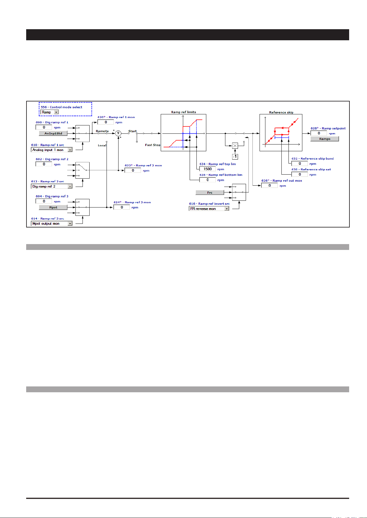
5.4 610 Ramp ref 1 src LINK 16/32 1500 0 16384 RW FVS
5.5 612 Ramp ref 2 src LINK 16/32 602 0 16384 ERW FVS
5.6 614 Ramp ref 3 src LINK 16/32 894 0 16384 ERW FVS
Selection of the origin (source) of the reference signals on the input of the ramp function block, that denes
the main drive speed. The ramp reference values can be selected from among those listed in the “L_MLTREF”
selection list.
When assigning the reference via terminals, signals with ±10V, 0 ...10V, 0... 20 mA and 4 ... 20 mA can be used.
Menu PAR Description UM Type FB BIT Def Min Max Acc Mod
5.7 616 Ramp ref invert src LINK 16 1050 0 16384 ERW FVS
Selection of the origin (source) of the signal that inverts the ramp reference output from the “Ramp ref” block. The
signal that can be used for this function can be selected from among those listed in the “L_DIGSEL2” selection list.
Menu PAR Description UM Type FB BIT Def Min Max Acc Mod
5.8 620 Ramp ref 1 mon FF INT16 0 0 0 R FVS
5.9 622 Ramp ref 2 mon FF INT16 0 0 0 ER FVS
5.10 624 Ramp ref 3 mon FF INT16 0 0 0 ER FVS
The value of the relative ramp reference on the output of the relative function block is displayed.
Menu PAR Description UM Type FB BIT Def Min Max Acc Mod
5.11 634 Ramp ref top lim FF INT32 0 0 CALCI ERWZ FVS
It denes the maximum value of the output of the ramp reference block, regardless of the signal that is present.
The ramp reference follows the reference signal from the value set in parameter PAR 636 Ramp ref bottom
lim up to the value set with this parameter, after which the motor speed remains constant. The limit is valid for
both directions of rotation.
26 ADV200 • Functions description and parameters list

Menu PAR Description UM Type FB BIT Def Min Max Acc Mod
Analog
Ramp
Reference in
5.12 636 Ramp ref bottom lim FF INT32 0 0 CALCI ERWZ FVS
It denes the minimum value of the output of the ramp reference block, regardless of the signal that is present.
The ramp block output remains at the value set with this parameter until the analog signal exceeds this threshold: the ramp output value then starts to follow the reference up to the value set in parameter PAR 634 Ramp
ref top lim. The limit is valid for both directions of rotation.
output
100 %
Par 636
- 100 %
- 10V
Par 634
Par 636
- 100 %
Menu PAR Description UM Type FB BIT Def Min Max Acc Mod
Par 634
0
100 %
10V
input
5.13 630 Reference skip set rpm INT16 0 0 CALCI ERW FVS
Setting of the prohibited speed threshold at which the drive cannot operate.
Menu PAR Description UM Type FB BIT Def Min Max Acc Mod
5.14 632 Reference skip band rpm INT16 0 0 CALCI ERW FVS
Setting of the prohibited bandwidth.
Reference out
Par. 632 Par. 632
Par. 630
Par. 630
Par632
Example:
A) Increase in the reference by values of less than Par. 630
Par. 630 = 300 rpm (prohibited speed threshold)
Par. 632 = 10 rpm (thus prohibited band: 290rpm.310rpm)
Set speed reference = 295 rpmHz
Output speed = 290 rpm
Set speed reference = 305 rpm
Output speed = 290 rpm
ADV200 • Functions description and parameters list 27

B) Decrease in the reference by values above Par. 630
Par.630 = 300 rpm (prohibited speed threshold)
Par.632 = 10 rpm (thus tolerance band: 290 rpm…310 rpm)
Set speed reference = 305 rpm
Output frequency = 310 rpm
Set speed reference = 295 rpm
Output frequency = 310 rpm
The user can thus set any reference value, but if the set value is within the prohibited range, the drive automati-
cally maintains the speed outside the limits dened by the tolerance band.
During ramp phases the prohibited speed is passed freely and there are no points of discontinuity in the generation of the output frequency.
The speed reference supplies the desired speed to the drive, which directly follows the reference pattern. This
only happens when the available torque is sufcient. In this case the drive functions at its current limit, until
reaching the set speed. The speed reference value determines the motor speed value. The sign determines the
direction of rotation.
Menu PAR Description UM Type FB BIT Def Min Max Acc Mod
5.15 640 Dig speed ref 1 FF INT16 16/32 0 CALCI CALCI ERW FVS
5.16 642 Dig speed ref 2 FF INT16 16/32 0 CALCI CALCI ERW FVS
Setting of the digital speed references. The overall speed reference is the result of the sum of the values with
the respective signs, of Dig speed ref 1 and Dig speed ref 2. The digital speed references are linked to the
ramp circuit output.
The overall speed reference is the result of the sum of the values, with sign, of Speed ref 1 and Speed ref 2.
Example 1: Speed ref 1 = + 500 rpm Speed ref 2 = + 300 rpm
Speed ref = 500 rpm + 300 rpm = 800 rpm
Example 2: Speed ref 1 = + 400 rpm Speed ref 2 = - 600 rpm
Speed ref = 400 rpm – 600 rpm = - 200 rpm
Menu PAR Description UM Type FB BIT Def Min Max Acc Mod
5.17 650 Speed ref 1 src LINK 16/32 640 0 16384 ERW FVS
5.18 652 Speed ref 2 src LINK 16/32 642 0 16384 ERW FVS
Selection of the origin (source) of the drive speed reference signals. The values that can be used as speed
28 ADV200 • Functions description and parameters list

references can be selected from those listed in the “L_MLTREF” selection list.
When assigning the reference via terminals, signals with ±10V, 0 ...10V, 0... 20 mA and 4 ... 20 mA can be
used.
Menu PAR Description UM Type FB BIT Def Min Max Acc Mod
5.19 654 Speed ref invert src LINK 16 6000 0 16384 ERWZ FVS
Selection of the origin (source) of the signal that inverts the speed reference output from the regulator. The terminal that can be used for this function can be selected from among those listed in the “L_DIGSEL2” selection list.
Menu PAR Description UM Type FB BIT Def Min Max Acc Mod
5.20 660 Speed ref 1 mon FF INT16 0 0 0 ER FVS
5.21 662 Speed ref 2 mon FF INT16 0 0 0 ER FVS
The value of the relative speed reference is displayed.
Menu PAR Description UM Type FB BIT Def Min Max Acc Mod
5.22 670 Speed ref top lim FF INT32 CALCI 0 CALCI ERWZ FVS
Setting of the upper speed reference limit. If the speed reference exceeds the limits, the motor speed remains
at the set limit value in any case. Speed limits cannot be more than 200% of the value set in the Full scale
speed parameter (REFENCES menu par. 680).
Menu PAR Description UM Type FB BIT Def Min Max Acc Mod
5.23 672 Speed ref bottom lim FF INT32 CALCI CALCI 0 ERWZ FVS
Setting of the lower speed reference limit. If the speed reference exceeds the limits, the motor speed remains
at the set limit value in any case. Speed limits cannot be more than 200% of the value set in the Full scale
speed parameter (REFERENCES menu par. 680).
Menu PAR Description UM Type FB BIT Def Min Max Acc Mod
5.24 666 Speed ref filter ms UINT16 0 0 1000 ERW FVS
Settting of the lter to the speed reference value. If IPA 666 Speed ref lter is set to 0, lter is disabled.
Menu PAR Description UM Type FB BIT Def Min Max Acc Mod
5.25 680 Full scale speed rpm INT16 CALCI 50 32000 RWZ FVS
Setting of the reference value for all speed percentage data (References, Speed adaptives ...) corresponding
to 100 % of the actual speed. This parameter can only be changed with the inverter blocked (Enable drive =
Disabled). The recommended setting for the value of this parameter is the motor rated speed. If altered, the
self-tuning procedure should be repeated.
Full scale speed does not dene the maximum possible speed. In any case, the maximum
speed percentage value is ± 200 % of the Full scale speed value.
Menu PAR Description UM Type FB BIT Def Min Max Acc Mod
5.26 222 Theta ref src LINK 16/32 220 0 16384 ERW F_S
Selection of the origin (source) of the ux reference. It requires the use of the EXP-FL-XCAN-ADV option and it
is needed to manage multi-windings asynchronous motors.
Additional technical informations are available through the Quick startup manual.
Value can be selected from among those listed in the “L_MLTREF” selection list.
Menu PAR Description UM Type FB BIT Def Min Max Acc Mod
5.27 226 Flux ref mon LINK 16/32 224 0 16384 ERW F_S
Selection of the origin (source) of electrical agle of the motor. It requires the use of the EXP-FL-XCAN-ADV option and it is needed to manage multi-windings asynchronous motors.
Additional technical informations are available through the Quick startup manual.
Value can be selected from among those listed in the “L_MLTREF” selection list.
ADV200 • Functions description and parameters list 29

6 – RAMPS
The ramp (reference integrator) determines the acceleration and deceleration times of the drive. Times can be set
independently.
The ramp times of Fast stop command are set on Acceleration time 3 and Deceleration time 3. The command can
be enabled from the terminal strip..
The ramp can be linear or S-shaped, as preferred.
The references can be set in different ways:
- with the Ramp ref 1 and / or Ramp ref 2 references
- with the Multi speed function
- with the Motor potentiometer function
- with the Jog function
The ramp generator can be used in the “stand alone” mode. When disabled (Ramp type = Off), the “Enable drive,
Start/Stop and Fast stop” commands do not affect the ramp generator. In this condition the ramp generator can be
used separately.
Menu PAR Description UM Type FB BIT Def Min Max Acc Mod
6.1 700 Acceleration time 0 s FLOAT 10.00 0.01 1000.00 RW FVS
6.2 702 Deceleration time 0 s FLOAT 10.00 0.01 1000.00 RW FVS
6.3 704 Acceleration time 1 s FLOAT 10.00 0.01 1000.00 ERW FVS
6.4 706 Deceleration time 1 s FLOAT 10.00 0.01 1000.00 ERW FVS
6.5 708 Acceleration time 2 s FLOAT 10.00 0.01 1000.00 ERW FVS
6.6 710 Deceleration time 2 s FLOAT 10.00 0.01 1000.00 ERW FVS
6.7 712 Acceleration time 3 s FLOAT 10.00 0.01 1000.00 ERW FVS
6.8 714 Deceleration time 3 s FLOAT 10.00 0.01 1000.00 ERW FVS
The acceleration and deceleration ramp times are used to avoid sudden changes in the drive output frequency,
which could cause mechanical shocks, excessive current on the motor and excessive DC-bus voltage values.
The acceleration times (6.1, 6.3, 6.5, 6.7) are expressed as the time necessary to bring the frequency from
30 ADV200 • Functions description and parameters list

zero to the maximum value set in the Full scale speed (5.22). On the other hand, the deceleration times (6.2,
f
t
Frequency
6.4, 6.6, 6.8 ) are expressed as the time necessary to bring the frequency from the maximum value set in the
Full scale speed (5.22) parameter to zero. Each of the 4 available ramp selections can be selected using one
or two digital inputs programmed as Multi ramp sel.
Menu PAR Description UM Type FB BIT Def Min Max Acc Mod
6.9 720 Ramp type ENUM Linear 0 3 ERWZ FVS
This parameter denes the ramp shape (linear/S-shape). It can only be modied with the drive disabled.
0 Linear
1 S-Shape
2 Bypass
3 Off
6.13 6.13 6.14 6.14
6.1 6.2
T
ACC TIME DEC TIME
0 = Linear 1 = S-Shape
When linear ramps are set (Linear) the motor speed varies in a way that is directly in proportion to
the frequency.
When S-shape ramps are set (S-Shape) it is possible to avoid sudden mechanical variations in the system at
the beginning and end of the acceleration and deceleration phase.
The ramp time, meaning the time necessary to accelerate from zero to the maximum frequency value
set, is given by the sum of the linear ramp time and that of the associated Jerks (see par. 6.13 – 6.20).
The Bypass excludes the ramp circuit and the reference is brought directly to the speed regulator input.
With Off the ramp reference is set to zero.
Menu PAR Description UM Type FB BIT Def Min Max Acc Mod
6.10 722 Multi ramp sel 0 src LINK 6000 0 16384 ERWZ FVS
6.11 724 Multi ramp sel 1 src LINK 6000 0 16384 ERWZ FVS
1 or 2 digital inputs can be used to select one of the 4 available sets of ramps.
The origin (source) of the command to enable the ramp selection function can be selected from the “L_DIGSEL2” selection list.
The following table describes the ramp selection procedure:
Enabled ramp time Multi ramp sel 0 Multi ramp sel 1
Acceleration time 0
Deceleration time 0
Acceleration time 1
Deceleration time 1
Acceleration time 2
Deceleration time 2
Acceleration time 3
Deceleration time 3
ADV200 • Functions description and parameters list 31
0 0
1 0
0 1
1 1

Menu PAR Description UM Type FB BIT Def Min Max Acc Mod
t
6.12 726 Multi ramp sel mon UINT16 0 0 3 ER FVS
The set of acceleration/deceleration ramps selected using the digital inputs is displayed.
Menu PAR Description UM Type FB BIT Def Min Max Acc Mod
6.13 730 Accel jerk time 0 s FLOAT 1.0 0.02 10.0 ERW FVS
6.14 732 Decel jerk time 0 s FLOAT 1.0 0.02 10.0 ERW FVS
6.15 734 Accel jerk time 1 s FLOAT 1.0 0.02 10.0 ERW FVS
6.16 736 Decel jerk time 1 s FLOAT 1.0 0.02 10.0 ERW FVS
6.17 738 Accel jerk time 2 s FLOAT 1.0 0.02 10.0 ERW FVS
6.18 740 Decel jerk time 2 s FLOAT 1.0 0.02 10.0 ERW FVS
6.19 742 Accel jerk time 3 s FLOAT 1.0 0.02 10.0 ERW FVS
6.20 744 Decel jerk time 3 s FLOAT 1.0 0.02 10.0 ERW FVS
Jerks are variations of acceleration in time. They are used when there is a need to dampen the beginning and
end of the ramp. The Jerk value is added, regardless of the variation in speed, to the linear ramp time.
f
6.13 6.13 6.14 6.14
ACC TIME DEC TIME
Menu PAR Description UM Type FB BIT Def Min Max Acc Mod
6.21 750 Ramp in zero src LINK 16 6000 0 16384 ERW FVS
Selection of the origin (source) of the signal that blocks the ramp input and moves the reference to zero. If the
ramp input is enabled, the Ramp ref parameter corresponds to the set reference. If the ramp input is blocked,
the drive slows down with the set deceleration time until reaching zero speed. The terminal to be associated
with this function can be selected from the “L_DIGSEL2” selection list.
Menu PAR Description UM Type FB BIT Def Min Max Acc Mod
6.22 752 Ramp out zero src LINK 16 6000 0 16384 ERW FVS
Selection of the origin (source) of the signal that brings the ramp to 0 (Ramp ref 1/Ramp ref 2 = 0). When the
ramp output is set to zero using Ramp out zero, the drive brakes with the maximum available torque; in this
case the ramp is disabled. The terminal to be associated with this function can be selected from the “L_DIG-
SEL2” selection list.
Menu PAR Description UM Type FB BIT Def Min Max Acc Mod
6.23 754 Ramp freeze src LINK 16 3480 0 16384 ERW FVS
Selection of the origin (source) of the signal that temporarily freezes the ramp output value, regardless of any
changes in the input reference. The terminal to be associated with this function can be selected from the “L_
DIGSEL2” selection list.
32 ADV200 • Functions description and parameters list

Ramp freeze
Ramp
(Motor
Output
speed)
ADV200 • Functions description and parameters list 33

7 – MULTI REFERENCE
With the “Multispeed” function (Multi references) it is possible to recall up to sixteen internally saved speed references to be recalled using a digital signal or via digital inputs on the terminal strip.
Menu PAR Description UM Type FB BIT Def Min Max Acc Mod
7.1 800 Multi reference 0 FF INT16 16/32 0 CALCI CALCI RW FVS
7.2 802 Multi reference 1 FF INT16 16/32 0 CALCI CALCI RW FVS
7.3 804 Multi reference 2 FF INT16 0 CALCI CALCI RW FVS
7.4 806 Multi reference 3 FF INT16 0 CALCI CALCI RW FVS
7.5 808 Multi reference 4 FF INT16 0 CALCI CALCI RW FVS
7.6 810 Multi reference 5 FF INT16 0 CALCI CALCI RW FVS
34 ADV200 • Functions description and parameters list

7.7 812 Multi reference 6 FF INT16 0 CALCI CALCI RW FVS
7.8 814 Multi reference 7 FF INT16 0 CALCI CALCI RW FVS
7.9 816 Multi reference 8 FF INT16 0 CALCI CALCI ERW FVS
7.10 818 Multi reference 9 FF INT16 0 CALCI CALCI ERW FVS
7.11 820 Multi reference 10 FF INT16 0 CALCI CALCI ERW FVS
7.12 822 Multi reference 11 FF INT16 0 CALCI CALCI ERW FVS
7.13 824 Multi reference 12 FF INT16 0 CALCI CALCI ERW FVS
7.14 826 Multi reference 13 FF INT16 0 CALCI CALCI ERW FVS
7.15 828 Multi reference 14 FF INT16 0 CALCI CALCI ERW FVS
7.16 830 Multi reference 15 FF INT16 0 CALCI CALCI ERW FVS
It is possible to select up to 16 operating frequencies, which can be set in these parameters.
The frequencies are selected using the binary code of the digital inputs programmed using the Multi ref sel 0
src, Multi ref sel 1 src, Multi ref sel 2 src and Multi ref sel 3 src parameters.
References can be set via the keypad, serial line, digital inputs and Fieldbus.
A sign can be given to the references, so that when they are dened so too is the desired direction of rotation.
Menu PAR Description UM Type FB BIT Def Min Max Acc Mod
7.17 832 Multi ref 0 src LINK 16/32 800 0 16384 RW FVS
7.18 834 Multi ref 1 src LINK 16/32 802 0 16384 RW FVS
Selection of the origin (source) of the drive speed reference signals. The speed reference values can be selected from those listed in the “L_MLTREF” selection list.
Menu PAR Description UM Type FB BIT Def Min Max Acc Mod
7.19 840 Multi ref sel 0 src LINK 16 6000 0 16384 RW FVS
7.20 842 Multi ref sel 1 src LINK 16 6000 0 16384 RW FVS
7.21 844 Multi ref sel 2 src LINK 16 6000 0 16384 RW FVS
7.22 846 Multi ref sel 3 src LINK 16 6000 0 16384 ERW FVS
Selection of the origin (source) of the signals used to select one of the preset speeds. These parameters can
only be used together in combinations. The terminals that can be used for this function can be selected from
among those listed in the “L_DIGSEL2” selection list.
The following table describes the selection of the Multispeed function:
Active speed ref Multi ref sel 0 src Multi ref sel 1 src Multi ref sel 2 src Multi ref sel 3 src
Multi reference 0 0 0 0 0
Multi reference 1 1 0 0 0
Multi reference 2 0 1 0 0
Multi reference 3 1 1 0 0
Multi reference 4 0 0 1 0
Multi reference 5 1 0 1 0
Multi reference 6 0 1 1 0
Multi reference 7 1 1 1 0
Multi reference 8 0 0 0 1
Multi reference 9 1 0 0 1
Multi reference 10 0 1 0 1
Multi reference 11 1 1 0 1
Multi reference 12 0 0 1 1
Multi reference 13 1 0 1 1
ADV200 • Functions description and parameters list 35
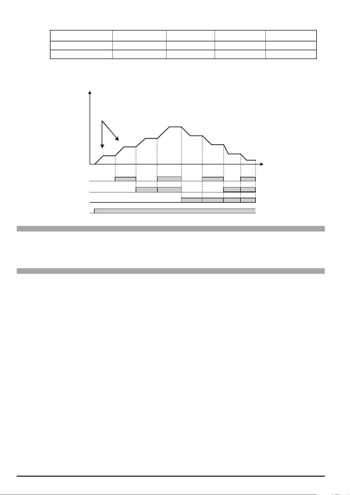
Active speed ref Multi ref sel 0 src Multi ref sel 1 src Multi ref sel 2 src Multi ref sel 3 src
Start
Multi reference 14 0 1 1 1
Multi reference 15 1 1 1 1
The following gure describes the selection of a control for 8 Multispeeds.
Speed
Selected by:
Multi ref0 src (par. 832)
Multi ref1 src (par. 834)
Multi ref 3
Multi ref2
Multi ref 1
Multi ref 0
Multi ref sel 0src
Multi ref sel1 src
Multi ref sel 2src
Multi ref 4
Multi ref 5
Multi ref 6
Multi ref 7
t
Menu PAR Description UM Type FB BIT Def Min Max Acc Mod
7.23 850 Multi ref sel mon UINT16 0 0 15 R FVS
The multispeed that has been selected using the digital commands or by the digital inputs selected in the terminal strip.
Menu PAR Description UM Type FB BIT Def Min Max Acc Mod
7.24 852 Multi ref out mon FF INT16 16/32 0 0 0 R FVS
The selected speed reference on the Multispeed block output is displayed.
36 ADV200 • Functions description and parameters list
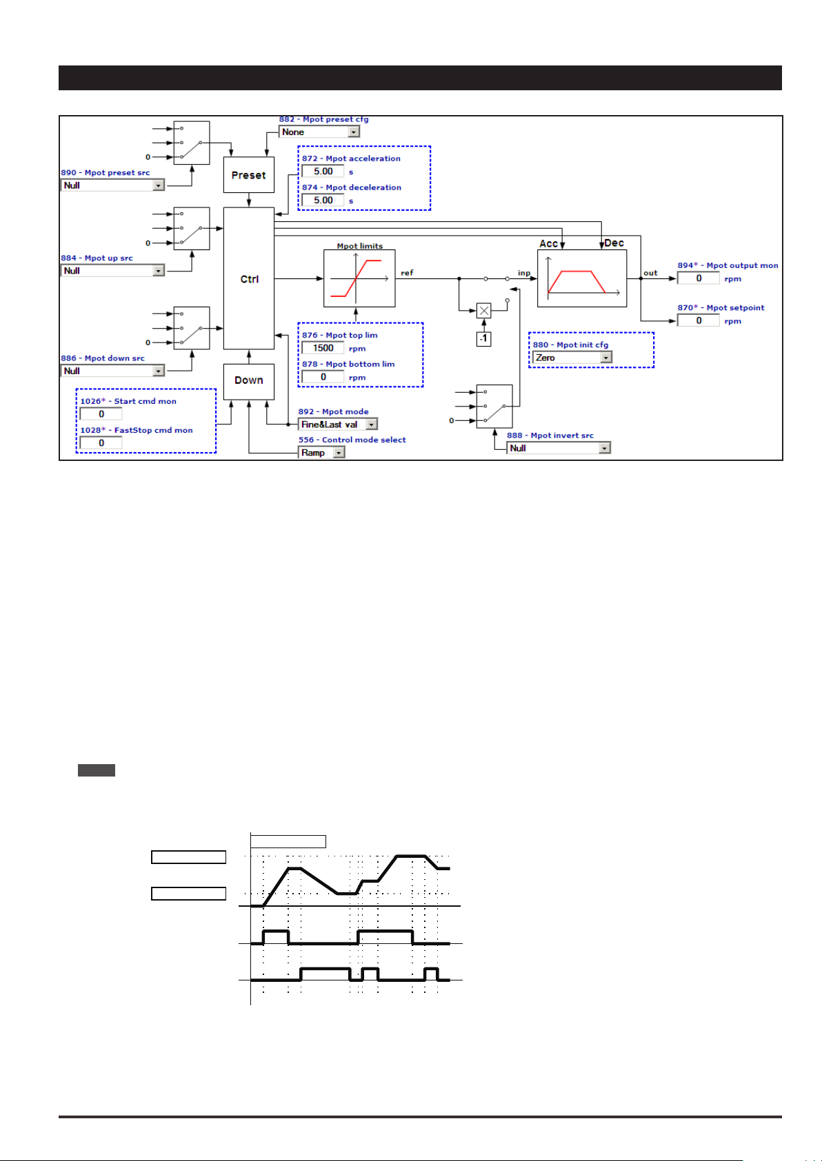
8 – MOTORPOTENTIOMETER
The Motor potentiometer function allows the speed reference of the drive to be changed by pressing buttons with
which the UP and DOWN commands are associated.
The UP and DOWN commands can be sent from the keypad, by digital inputs, the serial line or eldbus.
To send the UP and DOWN commands from the keypad, enter the MPot setpoint parameter modify mode and press
the UP and DOWN keys.
The UP and DOWN commands increase or decrease the speed of the motor for as long as they are present. The
simultaneous presence of both commands will not produce any change (see time chart).
The speed changes according to the set ramp times and within the set lower and upper limits.
The value of the Motor potentiometer function output at drive power-on can be congured.
The preset command can be used to force a preset value for the input and output of the Motor potentiometer function.
The invert command can be used to force an inversion of the reference sign of the Motor potentiometer function.
In the default condition, the speed reference produced by the Motor potentiometer function is connected in input to the
Ramp function. For direct control of the motor speed, the Acceleration time and Deceleration time parameters in the
RAMP menu should be set = 0.
Note ! The Motor potentiometer function produces a speed reference. Therefore a RUN command must always be sent to start motor
rotation.
Mpot output mon
Mpot top lim
Mpot bottom lim
Up
Down
ADV200 • Functions description and parameters list 37

Menu PAR Description UM Type FB BIT Def Min Max Acc Mod
8.1 870 Mpot setpoint FF INT16 16/32 0 CALCI CALCI R FVS
The speed reference value of the Motor potentiometer function is displayed. Default setting is “rpm”. It can be
modied thru the DIMENSION FACT function.
Enter this parameter to send the UP and DOWN commands from the keypad.
Menu PAR Description UM Type FB BIT Def Min Max Acc Mod
8.2 872 Mpot acceleration s FLOAT 5.0 0.01 1000.00 RW FVS
8.3 874 Mpot deceleration s FLOAT 5.0 0.01 1000.00 RW FVS
Setting of the acceleration/deceleration ramp times (in seconds) used with the Motor potentiometer function.
Menu PAR Description UM Type FB BIT Def Min Max Acc Mod
8.4 876 Mpot top lim FF INT16
CALCI
CALCI CALCI ERW FVS
Setting of the top limit for the speed reference output from the motor potentiometer.
Menu PAR Description UM Type FB BIT Def Min Max Acc Mod
8.5 878 Mpot bottom limit FF INT16 0 CALCI CALCI ERW FVS
Setting of the bottom limit for the speed reference output from the motor potentiometer.
Menu PAR Description UM Type FB BIT Def Min Max Acc Mod
8.6 880 Mpot init cfg ENUM Zero 0 3 ERW FVS
Use this parameter to congure the output value of the Motor potentiometer at drive start-up.
0 Last power off
1 Zero
2 Lower Limit
3 Upper Limit
When set to Last power off, the motor potentiometer output starts from the last frequency that was set before
the drive was switched off.
When set to Zero the motor potentiometer output starts from a value of 0.
When set to Lower limit the output of the motor potentiometer starts from the value of the lower limit set in the
Mpot bottom limit parameter.
When set to Upper limit the output of the motor potentiometer starts from the value of the upper limit set in the
Mpot top limit parameter.
Menu PAR Description UM Type FB BIT Def Min Max Acc Mod
8.7 882 Mpot preset cfg ENUM None 0 11 ERW FVS
This parameter can be used to congure the preset of the Motor potentiometer function, i.e. to congure the
value at which the Motor potentiometer input and output are set when the Preset command is enabled.
The Preset command has priority over the Up command and the Down command.
Mpot mode (PAR 892) = [1] Ramp&Follow has priority over the Preset command, i.e. actions programmed
with Mpot preset cfg (PAR 882) are not executed.
The Up and Down commands are enabled again when the Preset command is disabled.
0 None
1 Input = 0
2 Input = low lim
3 Input & ref = 0
4 Input & ref = low lim
5 Output = 0
38 ADV200 • Functions description and parameters list

6 Output = low lim
7 Output & ref = 0
8 Output & ref = low lim
9 Input = upp lim
10 Input & ref = upp lim
11 Freeze input
When set to None, no setting is executed.
Input = 0 sets input = 0 i.e. a temporary reference setting is performed and the previous reference value is
maintained. The output of the Motor potentiometer function varies with the set ramp times. The previous reference value is restored when the preset command is removed.
Input = low lim sets Inp = low lim i.e. a temporary reference setting is performed and the previous reference
value is maintained. The output of the Motor potentiometer function varies with the set ramp times. The previous reference value is restored when the preset command is removed.
Input & ref = 0 sets Inp = 0 and Ref = 0 i.e. a denitive reference setting is performed. The output of the Motor
potentiometer function varies with the set ramp times.
Input & ref = low lim sets Inp = low lim and Ref = low lim i.e. a denitive reference setting is performed. The
output of the Motor potentiometer function varies with the set ramp times.
Output = 0 sets Out = 0 i.e. a temporary output setting for the Motor potentiometer function is performed. The
previous reference value is maintained. If the preset command is enabled, the output of the Motor potentiometer function continues to be = 0, if the preset command is not enabled the output of the Motor potentiometer
function varies with the set ramp times.
Output = low lim sets Out = low lim i.e. a temporary setting for the output of the Motor potentiometer function
is performed.The previous reference value is maintained. If the preset command is enabled, the output of the
Motor potentiometer function continues to be = low lim, if the preset command is not enabled the output of the
Motor potentiometer function varies with the set ramp times.
Output & ref = 0 sets Out = 0 i.e. a denitive setting for the output of the Motor potentiometer function is per-
formed.
Output & ref = low lim sets Out = low lim i.e. a denitive setting for the output of the Motor potentiometer func-
tion is performed.
Input = upp lim sets Inp = upp lim i.e. a temporary setting for the reference is performed and the previous reference value is maintained. The output of the Motor potentiometer function varies with the set ramp times. The
previous reference value is restored when the preset command is removed.
Input & ref = upp lim sets Inp = upp lim and Ref = upp lim i.e. a denitive reference setting is performed. The
output of the Motor potentiometer function varies with the set ramp times.
When Freeze input is set, the Up and Down commands are temporarily disabled.
Menu PAR Description UM Type FB BIT Def Min Max Acc Mod
8.8 884 Mpot up src LINK 16 6000 0 16384 RW FVS
Selection of the origin (source) of the signal that increases the speed reference of the motor potentiometer with
the set ramp. The terminal to be associated with this function can be selected from the “L_DIGSEL2” selection
list.
Menu PAR Description UM Type FB BIT Def Min Max Acc Mod
8.9 886 Mpot down src LINK 16 6000 0 16384 RW FVS
Selection of the origin (source) of the signal that decreases the speed reference of the motor potentiometer
with the set ramp. The terminal to be associated with this function can be selected from the “L_DIGSEL2”
selection list.
Menu PAR Description UM Type FB BIT Def Min Max Acc Mod
8.10 888 Mpot invert src LINK 16 6000 0 16384 ERW FVS
Selection of the origin (source) of the signal that inverts the speed reference of the motor potentiometer. The
ADV200 • Functions description and parameters list 39

terminal to be associated with this function can be selected from the “L_DIGSEL2” selection list.
Menu PAR Description UM Type FB BIT Def Min Max Acc Mod
8.11 890 Mpot preset src LINK 16 6000 0 16384 ERW FVS
Selection of the origin (source) of the signal to preset the motor potentiometer function. The signal to be associated with this function can be selected from the “L_DIGSEL2” selection list.
Menu PAR Description UM Type FB BIT Def Min Max Acc Mod
8.12 892 Mpot mode ENUM
Fine&Last val
0 3 ERW FVS
Setting of the conguration of two possible options of the Motor potentiometer function. There are two operating
modes for each of the two options.
0 Ramp&Last val
1 Ramp&Follow
2 Fine&Last val
3 Fine&Follow
Option 1: Behaviour of the Motor potentiometer function with the Stop or FastStop command present with the
PAR 556 Control mode = Ramp parameter.
The two operating modes are: Last val or Follow.
With the Control mode not equal to Ramp setting, this option is not completely applicable and it always behaves in Last val mode.
In Last val mode with the Stop or FastStop command present, the speed reference of the Motor potentiometer
function is not altered.
The motor speed moves to 0 according to the selected control mode (Control mode = Ramp or Control mode
= Speed). When the Run command is sent, the motor speed moves to the speed reference set by the motor
potentiometer function according to the selected control mode.
Mpot output mon Mode:Last val
Up
Down
Start
In Follow mode with the Stop or FastStop command present, the Down command is simulated, i.e. the output
of the Motor potentiometer function moves to 0 with the set ramp time.
If the Run command is sent when the 0 speed has been reached, it is maintained until the Up command is
sent. If the Run command is sent before the motor reaches the 0 speed, the speed at that moment is taken as
the new reference.
40 ADV200 • Functions description and parameters list

Mpot output mon Mode:Follow
Up
Down
Start
Option 2: Ramp behaviour
The two operating modes are: Ramp or Fine
In Ramp mode, each time the Up or Down commands are enabled, the output of the Motor potentiometer func-
tion increases or decreases with the set ramp. When the Up or Down command is removed, the last value that
was reached is maintained.
Mpot output mon Mode:Ramp
Up
Down
In Fine mode, each time the Up or Down commands are enabled, the output of the Motor potentiometer function increases or decreases by 1 rpm.
If the command persists for less than 1 second, no other changes are made on the output.
If the command persists for more than 1 second, the output increases or decreases with the set ramp. The vari-
ation with the set ramp is performed gradually (1 second). When the Up or Down command is removed the last
value that was reached is maintained.
Mpot output mon
1rpm
1rpm
Up
Down
Mode:Fine
1s 1s
Behaviour of the Motor potentiometer function with
Mpot mode Ramp behaviour
the Stop or FastStop command present with the
Control mode = Ramp parameter.
0 Ramp Last val
1 Ramp Follow
2 Fine Last val
3 Fine Follow
ADV200 • Functions description and parameters list 41

Menu PAR Description UM Type FB BIT Def Min Max Acc Mod
UP DOWN
Speed
Command console
8.13 894 Mpot output mon rpm INT16 16/32 0 0 0 ER FVS
The value of the output of the motor potentiometer function is displayed.
Two examples of application of the motor potentiometer function are shown below.
Manual speed control with command sent from external control desk.
M
ADV
Mpot up
Mpot down
The Up and Down keys are used to adjust the speed of a motor.
For ne-tuning of the speed reference value the recommended settings are Mpot Mode = Fine&Follow or
Fine&Last Val. Each time they are pressed for 1 second, the speed increases by 1 rpm. For an immediate ef-
fect on motor speed, the Acceleration time and Deceleration time parameters should be set to short times.
Automatic speed control for rudimentary dancer control.
24V
24V
Mpot down
Mpot up
M
ADV
2
10V
M
ADV
1
To p
Center
Bottom
Ramp ref
0V
The limit switches at the ends of dancer travel ranges are connected to the Up and Down commands in the motor potentiometer function. If the dancer presses the bottom limit switch, this means motor 2 is running slowly
and the Up command must be sent. If the dancer presses the top limit switch, this means motor 2 is running
quickly and the Down command must be sent.
Connect the line reference to Ramp ref 1 src on both drives, connect the motor potentiometer function output
to Speed ref 1 src on drive 2.
To change the motor speed immediately, the recommended settings are Mpot Mode = Ramp&Follow or
Rampa&Last Val.
42 ADV200 • Functions description and parameters list

9 – JOG FUNCTION
Menu PAR Description UM Type FB BIT Def Min Max Acc Mod
9.1 910 Jog setpoint rpm INT16 0 CALCI CALCI RW FVS
The reference for Jog mode operation. This reference can also be set via an analog input. The Jog reference
is enabled when the signal used for the Jog + or Jog – command is enabled, the Run command is not present
and the drive output frequency is zero.
Menu PAR Description UM Type FB BIT Def Min Max Acc Mod
9.2 912 Jog acceleration s FLOAT 5.0 0.01 1000.00 RW FVS
9.3 914 Jog deceleration s FLOAT 5.0 0.01 1000.00 RW FVS
Setting of the acceleration/deceleration ramp time (in seconds) used during Jog operation.
Menu PAR Description UM Type FB BIT Def Min Max Acc Mod
9.4 916 Jog cmd + src LINK 16 6000 0 16384 RW FVS
Selection of the origin (source) of the Jog + function enabling signal. When this command is enabled it gener-
ates a Jog Mode reference with a sign matching the value entered for the Jog setpoint value parameter. The
signal to be associated with this function can be selected from the “L_DIGSEL2” selection list.
Note ! The Run command has priority over the Jog + command.
Menu PAR Description UM Type FB BIT Def Min Max Acc Mod
9.5 918 Jog cmd - src LINK 16 6000 0 16384 RW FVS
Selection of the origin (source) of the Jog - function enabling signal. When this command is enabled the Jog
Mode reference sign is inverted with respect to the value entered in the Jog setpoint value parameter. The
signal to be associated with this function can be selected from the “L_DIGSEL2” selection list.
Note ! The Run command has priority over the Jog - command.
Menu PAR Description UM Type FB BIT Def Min Max Acc Mod
9.6 920 Jog output mon rpm INT16 16/32 0 0 0 ER FVS
The speed reference used by the Jog command is displayed.
ADV200 • Functions description and parameters list 43

10 – MONITOR FUNCTION
Menu PAR Description UM Type FB BIT Def Min Max Acc Mod
10.1 930 Reference 0 thr rpm INT16 30 0 CALCI RW FVS
Setting of the threshold for recognition of the speed = 0 reference. The value is valid for both directions of rotation.
Menu PAR Description UM Type FB BIT Def Min Max Acc Mod
10.2 932 Reference 0 delay ms UINT16 400 0 10000 RW FVS
Setting of the delay in milliseconds after which the reference = 0 reached signal is enabled.
Menu PAR Description UM Type FB BIT Def Min Max Acc Mod
10.3 940 Speed 0 thr rpm INT16 30 0 CALCI RW FVS
Setting of the threshold for recognizing speed value = 0. The value is valid for both directions of rotation.
Menu PAR Description UM Type FB BIT Def Min Max Acc Mod
10.4 942 Speed 0 delay ms UINT16 400 0 10000 RW FVS
Setting of the delay in milliseconds after which the speed = 0 reached signal is enabled.
When the motor reaches a speed that is below the zero speed threshold, it stops and the
n=0
LED lights up.
44 ADV200 • Functions description and parameters list

Menu PAR Description UM Type FB BIT Def Min Max Acc Mod
10.5 950 Speed threshold 1 rpm INT32 0 CALCI CALCI RW FVS
Setting of speed threshold 1 (upper). When the threshold is exceeded the Speed threshold signal is disabled,
with a delay that can be set in Speed threshold dly.
Menu PAR Description UM Type FB BIT Def Min Max Acc Mod
10.6 952 Speed threshold 2 rpm INT32 0 CALCI CALCI RW FVS
Setting of speed threshold 2 (lower). When the threshold is exceeded the Speed threshold signal is disabled,
with a delay that can be set in Speed threshold dly.
Menu PAR Description UM Type FB BIT Def Min Max Acc Mod
10.7 954 Speed threshold dly ms UINT16 0 0 50000 RW FVS
Setting of the delay after which the transition from 0 c1 is activated. The transition from 0 c1 occurs when the
speed is within the set limits. The Speed threshold signal transition from 1 c 0 is always immediate.
If the motor speed is between Speed threshold 1 and Speed threshold 2, the Speed threshold signal is active. If Speed threshold 1 < Speed threshold 2 the Speed threshold signal is not signicant.
Menu PAR Description UM Type FB BIT Def Min Max Acc Mod
10.8 960 Set speed ref src LINK 16/32 628 0 16384 ERW FVS
Selection of the origin (source) of the signal used as speed reference and on which the speed reached control
is performed (for control with ramp, use Ramp setpoint, for control without ramp, use Speed setpoint). The
signal that can be used as the speed reference can be selected from among those listed in the “L_CMP” selection list.
Menu PAR Description UM Type FB BIT Def Min Max Acc Mod
10.9 962 Set speed error rpm INT16 100 0 CALCI RW FVS
Setting of the bandwidth of the tolerance within which, even if the speed is not equal to the reference, the two
values are considered to coincide and the Set speed signal is enabled.
Menu PAR Description UM Type FB BIT Def Min Max Acc Mod
10.10 964 Set speed delay ms UINT16 0 0 50000 RW FVS
Setting of a delay in ms before the signal (Set speed programmed on a digital output), if the speed is within a
tolerance band dened by the Set speed error parameter, after which the transition from 0 c1 is enabled.
The transition of the Set Speed signal from 0 c1 is always immediate.
Menu PAR Description UM Type FB BIT Def Min Max Acc Mod
10.11 968 Dig set speed ref rpm UINT16 16/32BIT 0 CALCI CALCI RW FVS
Setting of the threshold used as the speed reference: this parameter is used to set a xed threshold regardless
of the speed reference.
ADV200 • Functions description and parameters list 45

Menu PAR Description UM Type FB BIT Def Min Max Acc Mod
10.12 970 Speed threshold 3 rpm INT32 0 0 CALCI ERW FVS
Setting of the speed 3 threshold. When this threshold + the tolerance band set in parameter 972 Speed thr
hysteresis are exceeded, parameter 976 Speed thr 3 mon is enabled. The signal is disabled when the motor
speed falls below the threshold - the tolerance band. If the threshold value is lower than the value set in 972
Speed thr hysteresis, the result produced is always 0. The value set in this parameter is active in both direc-
tions of rotation.
Menu PAR Description UM Type FB BIT Def Min Max Acc Mod
10.13 972 Speed thr hysteresis rpm UINT16 0 0 CALCI RW FVS
Setting of the tolerance band around Speed threshold 3. The tolerance band is the same for both directions of
rotation of the motor.
Menu PAR Description UM Type FB BIT Def Min Max Acc Mod
10.14 974 Speed thr 3 src LINK 16/32 262 0 16384 ERW FVS
Lets you select the source of the “Speed threshold 3” function block to compare Speed threshold 3 (IPA 970)
with the real or estimated motor speed or speed reference.
Menu PAR Description UM Type FB BIT Def Min Max Acc Mod
10.15 980 Current threshold perc UINT16 100 0 200 RW FVS
Setting of the current threshold. A value of 100% corresponds to the value of the drive heavy duty continuous
current, displayed in parameter 488 Drive cont current, when parameter 566 Drive overload mode is set
to Heavy duty, and no derating of the drive continuous current has been activated due to any modication of
Mains voltage, Switching frequency and Ambient temperature.
The drive heavy duty continuous current value to be used is the factory setting read in PAR 488 Drive cont
current.
When this threshold + the tolerance band set in parameter 982 C
urrent thr hyster
are exceeded, parameter 986
Current thr mon is enabled. The signal is disabled when the motor speed falls below the threshold - the toler-
ance band. If the threshold value is lower than the value set in 982 Current thr hyster, the result produced is
always 0. The value set in this parameter is active in both directions of rotation.ù
46 ADV200 • Functions description and parameters list

Menu PAR Description UM Type FB BIT Def Min Max Acc Mod
10.16 982 Current thr hyster perc UINT16 0 0 100 RW FVS
Setting of the tolerance band around the current threshold. A value of 100% corresponds to the value of the
drive heavy duty continuous current, displayed in parameter 488 Drive cont current, when parameter 566
Drive overload mode is set to Heavy duty, and no derating of the drive continuous current has been activated
due to any modication of Mains voltage, Switching frequency and Ambient temperature.
The drive heavy duty continuous current value to be used is the factory setting read in PAR 488 Drive cont
current.
The tolerance band is the same for both directions of rotation of the motor.
ADV200 • Functions description and parameters list 47

11 – COMMANDS
Local Remote
It is possible to work in Local or Remote mode.
Standard I/O
Terminal
Expansion I/O
Keypad
ADV200
Terminal
Digital
Standard I/O
Expansion I/O
Modbus
Field bus
Profile (DS402-Profidrive)
Ramp ref 3 Ramp ref 1
When switching between Remote and Local modes the origin of the Enable and Start commands is switched and in
the Ramp Ref block, switching occurs between Ramp ref 1 and Ramp ref 3.
In Remote mode the “Commands remote sel” parameter is used to congure the source of the Enable and Start
commands which can be Terminal (standard digital input, expansion digital input) or Digital (Modbus, Fieldbus, Prole
DS402, Prole prodrive).
In Local mode the “Commands local sel” parameter is used to congure the source of the Enable and Start commands, which can be Terminal (standard digital input, expansion digital input) or Keypad (Start key, Stop key).
In Remote c Digital mode the Digital Enable src and Digital Start src parameters must be used to congure the
source.
Normally the sources are the Pad parameters. Modbus or Fieldbus must therefore write the desired value on the Pad
parameters. Alternatively, the value of 6000 can be written directly on the Digital Enable src and Digital Start src
48 ADV200 • Functions description and parameters list

parameters for a source of Null (0) or the value of 6002 for a source of One (1).
Another alternative is to congure the Digital Enable src and Digital Start src sources on the BitX decomp mon
parameters, so that the Modbus or Fieldbus can then write the desired value on the Dig word decomp parameter.
Local n Remote switching is performed with the variable value congured as Loc/Remote src, i.e. it can be a stand-
ard digital input, expansion digital input, Modbus, Fieldbus, Dig Local/Remote.
In the default condition, the associated variable is Dig Local/Remote, which is written by the LOC key from the keypad: switching is thus performed by pressing the LOC key.
For safety reasons, Local n Remote switching is only performed with Terminal Enable = 0.
Example 1
With the machine in automatic operating mode, the drive works in Remote -> Digital -> Fieldbus mode.
With the machine in manual operating mode, the drive works in Local -> Terminal -> Standard digital input mode.
If switching from automatic to manual machine operation, the drive must switch between Remote and Local mode. The
switch command must be sent via standard digital input or eldbus.
Example 2
With the machine controlled from console A, the drive operates in Local -> Terminal -> Standard digital input mode.
With the machine controlled from console B, the drive operates in Remote ->Digital -> Expansion digital input mode.
When switching the control console, the drive must switch between Remote and Local mode. The switch command
must be sent via Standard digital input or Expansion digital input.
This conguration is allowed because the Terminal variables are available in the digital command selection lists.
Menu PAR Description UM Type FB BIT Def Min Max Acc Mod
11.1 1000 Commands remote sel ENUM Terminals 0 1 RWZ FVS
This parameter denes the source of the command signals when the drive is used in the Remote mode.
The Enable command can only be set via hardware, connecting a positive voltage (+24VDC) to terminal 7.
0 Terminals
1 Digital
When the parameter is set to Terminals the source of the Enable cmd mon command is the Enable terminal
(7) and the origin of the Start cmd mon command is congured using the Terminal Start src parameter.
When the parameter is set to Digital the origin of the Enable cmd mon command is congured using the Dig-
ital Enable src parameter and the origin of the Start cmd mon command is congured using the Digital Start
src parameter.
If Digital is set to generate the Enable cmd mon command, as well as the variable associated with Digital Enable src, the enable hardware command must also be sent to the Enable terminal.
Menu PAR Description UM Type FB BIT Def Min Max Acc Mod
11.2 1002 Commands local sel ENUM Keypad 0 2 ERWZ FVS
This parameter denes the source of the command signals when the drive is used in the Local mode.
0 Terminals
2 Keypad
When the parameter is set to Terminals the source of the Enable cmd mon command is the Enable terminal
(7) and the origin of the Start cmd mon command is congured using the Terminal Start src parameter.
ADV200 • Functions description and parameters list 49

When the parameter is set to Keypad the origin of the Enable cmd mon and Start cmd mon commands is
the Start key. When Keypad is set to generate the Enable cmd mon command, as well as the Start key the
enable hardware command must also be sent to the Enable terminal (7).
Menu PAR Description UM Type FB BIT Def Min Max Acc Mod
11.3 1004 Enable/disable mode ENUM
This parameter is used to dene the generation of Enable cmd mon, i.e. to congure the type of control used
for enabling and disabling the drive.
0 Off
1 Stop/FS&Spd = 0
2 Stop&Spd = 0
3 FS&Spd = 0
If set to 0 Off:
In Terminal mode the drive is enabled and disabled via the Enable terminal.
In Digital mode the drive is enabled and disabled when the signal on the Enable terminal and the Digital En-
able command are present simultaneously.
In Keypad mode the drive is enabled if the hardware is enabled on the Enable terminal and the Start key is
pressed.
In Keypad mode it is disabled if the hardware is not enabled on the Enable terminal or if the Stop key is
pressed twice.
Stop/FS&Spd=0
0 3 ERWZ FVS
If 1 Stop/FS&Spd = 0 is set:
In Terminal mode the drive is enabled when the hardware is enabled on the Enable terminal, on the terminal
programmed as Terminal Start and the FastStop terminal must not be enabled.
In Terminal mode the drive is instantly disabled if there is no signal on the Enable terminal, or when speed=0
is reached if the Start command is disabled or the terminal programmed as FastStop is enabled.
In Digital mode the drive is enabled when the hardware is enabled on the Enable terminal, the Digital Enable,
In Digital mode the drive is instantly disabled if there is no signal on the Enable terminal, or when speed=0 is
reached if the Digital Start command is disabled or the terminal programmed as FastStop is enabled.
In Keypad mode the drive is enabled if the hardware is enabled on the Enable terminal and the Start key is
pressed, with the command disabled on the FastStop terminal.
In Keypad mode the drive is disabled instantly if the signal is not present on the Enable terminal or the Stop
key is pressed twice.
If 2 Stop&Spd = 0 is set:
In Terminal mode the drive is enabled if the hardware is enabled on the Enable terminal and the signal is ena-
bled on the terminal programmed as Terminal Start.
In Terminal mode the drive is instantly disabled if there is no signal on the Enable terminal, or if, upon reaching
the speed=0, the Terminal Start command is disabled.
In Digital mode the drive is enabled when the hardware is enabled on the Enable terminal and the Digital En-
able and DigitalStart signals are present.
In Digital mode the drive is instantly disabled if the signal is not present on the Enable terminal, or the Digital
Enable command is not present, or upon reaching the speed=0 if the Digital Start command is set to 0.
In Keypad mode the drive is enabled when the hardware is enabled on the Enable terminal and the Start key
is pressed.
In Keypad mode the drive is instantly disabled if the signal is not present on the Enable terminal or the Stop
key is pressed twice, or when the speed=0 is reached if the Stop key is pressed.
If 3 FS&Spd = 0 is set:
In Terminal mode the drive is enabled when the hardware is enabled on the Enable terminal and the FastStop
50 ADV200 • Functions description and parameters list

terminal is not enabled.
In Terminal mode the drive is instantly disabled if there is no signal on the Enable terminal, or when the
speed=0 is reached if the terminal programmed as FastStop is enabled.
In Digital mode the drive is enabled if the hardware is enabled on the Enable terminal and the Digital Enable
signal is present, with the command on the FastStop terminal disabled.
In Digital mode the drive is instantly disabled if there is no signal on the Enable terminal, or no Digital Enable
command, or when the speed=0 is reached if the Digital Start command is set to 0.
In Keypad mode the drive is enabled if the hardware is enabled on the Enable terminal and the Start key is
pressed, with the FastStop command disabled.
In Keypad mode the drive is instantly disabled if there is no signal on the Enable terminal or the Stop key is
pressed twice, or if, when the speed=0 is reached, the terminal programmed as FastStop is enabled.
Menu PAR Description UM Type FB BIT Def Min Max Acc Mod
11.4 1006 Speed 0 disable dly ms UINT16 1000 0 10000 ERW FVS
Setting of a delay in milliseconds between reaching the zero speed and disabling the drive when Enable/Disable mode is set to a value other than Off.
Menu PAR Description UM Type FB BIT Def Min Max Acc Mod
11.5 1008 Stop key mode ENUM Inactive 0 1 ERW FVS
Setting of the stop key functioning on the keypad. In Local with command from Keypad , this conguration is
ineffective.
Active in remote control mode (PAR 1012=1) both by using “Terminals” command or “Digital” commands and,
in local control mode (PAR 1012=0) by using “Terminals” command.
0 Inactive
1 EmgStop&Alarm
If the command is set to Inactive, pressing the Stop key on the keypad is ineffective.
If the command is set to EmgStop&Alarm, when the Stop key is pressed the motor stops in FastStop mode
and the Emg stop alarm is generated. When the motor reaches the speed=0, the drive is automatically disabled and waits for the Fault reset command. The Fault reset command must be sent twice to reset the drive.
Menu PAR Description UM Type FB BIT Def Min Max Acc Mod
11.6 1010 Commands safe start BIT 1 0 1 ERW FVS
This parameter is used to dene whether the safe start command is disabled or enabled at drive power-on.
0 Off
1 On
If set to Off, the safe start command is disabled. If the drive is powered-on with the hardware enabled on the
Enable terminal, the motor could start rotating.
When set to On, the safe start command is enabled. If the drive is powered-on with the hardware enabled on
the Enable terminal, the motor will not rotate. To set the drive to accept subsequent commands, open the hardware enabling contact on the Enable terminal and then close it again.
If the drive is restarted (and the Enable command is present), message [23] Safe start active is displayed.
Menu PAR Description UM Type FB BIT Def Min Max Acc Mod
11.7 1012 Dig local/remote ENUM 16 Remote 0 1 ERW FVS
Setting Local or Remote operating mode.
0 Local
1 Remote
Writing this parameter is only effective if it is associated with Local/Remote src and if performed without the
hardware enabled on the Enable terminal. Press LOC to modify the value of this parameter 0<->1.
To disable the LOC key, set Local/Remote src to a value other than Dig local/remote.
ADV200 • Functions description and parameters list 51

Menu PAR Description UM Type FB BIT Def Min Max Acc Mod
11.8 1014 Local/remote src LINK 16 1012 0 16384 ERW FVS
Selection of the origin (source) of the signal that switches between Remote and Local. Switching can only be
performed if the hardware is not enabled on the Enable terminal.
The signal to be associated with this function can be selected from the “L_DIGSEL3” selection list.
0 Local
1 Remote
In Remote mode the “Commands remote sel” parameter is used to congure the source of the Enable and
Start commands, which can be Terminal (standard digital input, expansion digital input) or Digital (Modbus,
Fieldbus, Prole DS402, Prole prodrive).
In Local mode the “Commands local sel” parameter is used to congure the source of the Enable and Start
commands, which can be Terminal (standard digital input, expansion digital input) or Keypad (Start key, Stop
key).
Menu PAR Description UM Type FB BIT Def Min Max Acc Mod
11.9 1016 Terminal Start src LINK 16 1048 0 16384 ERW FVS
Selection of the origin (source) of the Terminal Start signal. Switching can only be performed if the hardware is
not enabled on the Enable terminal.
The signal to be associated with this function can be selected from the “L_DIGSEL3” selection list.
In the default condition, the origin of the Terminal Start signal is the Start output of the ForwardReverseControl
(FRC) block.
Menu PAR Description UM Type FB BIT Def Min Max Acc Mod
11.10 1018 Digital Enable src LINK 16 6000 0 16384 ERW FVS
Selection of the origin (source) of the signal that denes the enabling of the drive when the commands are sent
via serial line or eldbus. The command to be associated with this function can be selected from the “L_DIG-
SEL2” selection list.
Menu PAR Description UM Type FB BIT Def Min Max Acc Mod
11.11 1020 Digital Start src LINK 16 6000 0 16384 ERW FVS
Selection of the origin (source) of the Digital Start signal. The signal to be associated with this function can be
selected from the “L_DIGSEL2” selection list.
Menu PAR Description UM Type FB BIT Def Min Max Acc Mod
11.12 1022 FastStop src LINK 16 6000 0 16384 ERW FVS
Selection of the origin (source) for the fast stop signal (FastStop). The terminal to be associated with this function can be selected from the “L_DIGSEL2” selection list. During the execution of the FastStop command the
ramps used are Acceleration time 3 and Deceleration time 3.
The FastStop mode (PAR 1036) parameter can be used to dene the specic operating modes for automatic
motor restart.
Menu PAR Description UM Type FB BIT Def Min Max Acc Mod
11.13 1024 Enable cmd mon BIT 16 0 0 1 R FVS
The status of the enable command is displayed.
Menu PAR Description UM Type FB BIT Def Min Max Acc Mod
11.14 1026 Start cmd mon BIT 16 0 0 1 R FVS
The status of the Start command is displayed.
Menu PAR Description UM Type FB BIT Def Min Max Acc Mod
11.15 1028 FastStop cmd mon BIT 16 0 0 1 R FVS
52 ADV200 • Functions description and parameters list
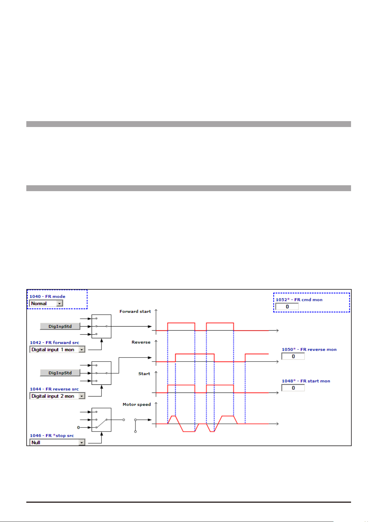
This parameter is used to display the value of the FastStop command state.
0 FastStop not active
1 FastStop active
If the “FastStop mode” parameter is set to 0 = “Not Latched”, the value of the FastStop command monitor
changes to 1 when the FastStop input is activated and remains high (1) until the Enable or FastStop inputs are
deactivated (0 state).
If the “FastStop mode” parameter is set to 1 = “Latched”, the value of the FastStop command monitor changes
to 1 when the FastStop input is activated and remains high (1) until the Enable, Start, FastStop inputs are
deactivated (0 state).
Menu PAR Description UM Type FB BIT Def Min Max Acc Mod
11.16 1054 Safe start mon BIT 16 0 0 1 ER FVS
Display of state of “check safe start” function:
0 Disable
1 Enable
The function is enabled with PAR 1010 Commands safe start.
Menu PAR Description UM Type FB BIT Def Min Max Acc Mod
11.17 1040 FR mode ENUM Normal 0 2 ERWZ FVS
Setting of the operating mode of the Forward Reverse Control (FRC) block.
0 Normal
1 Two wire Two wire control
2 Three wire Three wire control
The default use of the FRC block is shown below.
The Start command is linked to the Start terminal and the Reverse command is linked to Ramp ref invert.
The function diagrams of the 3 modes are shown below.
When 0 - Normal control is set the motor only starts rotating when the FR Forward command is sent. If the FR
Reverse command is present the motor rotates in the reverse direction,
The FR start mon output repeats the status of the FR Forward command, while the FR reverse mon output
repeats the status of the FR Reverse command.
ADV200 • Functions description and parameters list 53
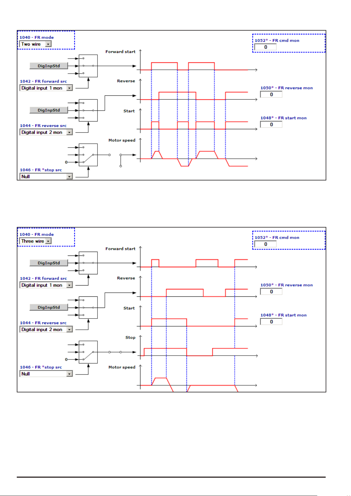
When set to 1 - Two wire control, the motor only rotates if the FR Forward command or FR Reverse com-
mand is present. The simultaneous presence of the FR Forward and FR Reverse commands causes the
motor to stop.
The FR start mon output is enabled if the FR Forward and FR Reverse commands are not present simultaneously.
The FR reverse mon output repeats the status of the FR Reverse command.
For 2 - Three wire control the FR *stop command must be present on a digital input programmed via the FR
*stop src parameter (not present in the default condition). When set to Three wire control, the motor starts
upon receiving an impulse of not less than 50 msec on the FR Forward terminal. Once the motor has started
the command is no longer necessary on the FR Forward terminal. To reverse the direction of rotation enable
the FR Reverse command: the motor will be brought to the zero speed with the set ramp and will restart in the
opposite direction of rotation. The motor rotates in the Reverse direction for as long as the FR Reverse signal
is enabled. If the FR Reverse signal is disabled the motor rotates in the Forward direction. To stop the motor
open the FR *stop contact.
54 ADV200 • Functions description and parameters list

Menu PAR Description UM Type FB BIT Def Min Max Acc Mod
11.18 1042 FR forward src LINK 16 1112 0 16384 ERW FVS
Selection of the origin (source) for the FR forwardstart signal. With this command the motor starts to rotate
(with the Enable command enabled). The terminal to be associated with this function can be selected from the
“L_DIGSEL2” selection list.
Menu PAR Description UM Type FB BIT Def Min Max Acc Mod
11.19 1044 FR reverse src LINK 16 1114 0 16384 ERW FVS
Selection of the origin (source) for the FR reverse signal. With this command the motor reverses the direction of rotation (with the Enable command enabled). The terminal to be associated with this function can be
selected from the “L_DIGSEL2” selection list.
Menu PAR Description UM Type FB BIT Def Min Max Acc Mod
11.20 1046 FR *stop src LINK 16 6000 0 16384 ERW FVS
Selection of the origin (source) for the FR stop signal. The terminal to be associated with this function can be
selected from the “L_DIGSEL2” selection list.
Menu PAR Description UM Type FB BIT Def Min Max Acc Mod
11.21 1048 FR start mon BIT 16 0 0 1 ER FVS
The status of the Start output of the Forward Reverse Control (FRC) block is displayed.
0 Stop
1 Start
Menu PAR Description UM Type FB BIT Def Min Max Acc Mod
11.22 1050 FR reverse mon BIT 16 0 0 1 ER FVS
The status of the Reverse output of the Forward Reverse Control (FRC) block is displayed.
0 No Reverse
1 Reverse
Menu PAR Description UM Type FB BIT Def Min Max Acc Mod
11.23 1052 FR cdm mon UINT16 0 0 0 ER FVS
The status of the commands of the Forward Reverse Control (FRC) block are displayed.
FR *stop src FR reverse src FR forward src FR cdm mon
0 0 0 0
0 0 1 1
0 1 0 2
0 1 1 3
1 0 0 4
1 0 1 5
1 1 0 6
1 1 1 7
Menu PAR Description UM Type FB BIT Def Min Max Acc Mod
11.24 1032 Drv Interlock src LINK 16 6002 0 16384 ERW FVS
This parameter is used to select the origin (source) of the Drv Interlock signal.
The signal to be associated with this function can be selected from the “L_DIGSEL2” selection list.
0 Drive interlock active (Drive disabled)
1 Drive interlock not active (Drive can be enabled)
ADV200 • Functions description and parameters list 55

If the Drive Interlock command is active, the drive cannot be enabled (Drive Enable command).
Drv interlock mon
If the Drive Interlock command is not active, the drive can be enabled by applying the Drive enable command.
In default conditions the “Drv Interlock src” signal is connected to “One”. In this conguration the Drive interlock function is not active and the drive can only be enabled with the “Enable” command.
Enable
Start
Drv interlock
S
Q
_Q
R
Enable cmd mon
The Drv Interlock signal, with the “EXP-SFTy-ADV” (ADV200.....-SI series) safety card, is used to disable the
drive under certain conditions and to prevent any dangerous situations from arising.
The drive reads the state of the Safety card via the Drv Interlock src input
The EXP-SFTy-ADV card can be connected to the drive as shown in the gure below.
ADV200
K
EXP-SFTy-ADV
+24V
0V
Enable
7C2R14 R11
Enable Stat mon
K1
Contatto NO
DIx
Safety
Enable
+24V
0V
If the “Drv Interlock” command is active (low state = 0) the drive is disabled immediately. To enable the drive
again, set the “Drv Interlock” command to the high state (1) (Drive interlock not active) and the “Enable” and
“Start” commands to the 0 state (Disabled and Stop) and then to the high state (1).
The “Drv Interlock” command must be sent before the “Enable” command.
The EXP-SFTy-ADV card supplies the Safety Enable Feedback digital output as shown in the following table.
12345
+24V
0V
Safety
Enable
Feedback
Rele K1
Safety Enable Safety Enable Feedback Description
Open 0V Safety function active
The drive does not supply current
+24V +24V Safety function not active
The drive can supply current
56 ADV200 • Functions description and parameters list

A relay (K1) can be used to repeat the safety card feedback signal. A normally
open (NO) contact of the relay can be connected to a drive input set to “Drv Interlock src”.
If the Safety card is active (the drive does not supply current) the Safety Enable Feedback digital output is set
to low (0), the relay is not excited and the NO contact is open.
When the “Drv interlock” signal receives a low command (0) (Drive interlock active) the drive is disabled.
The “Drv Interlock src” can be used to know the instantaneous state of the Safety Enable Feedback function.
The “Drv interlock mon” parameter can be used to know the state of the Safety Enable Feedback function taking into account the interlocking logic with the drive Enable command.
0 Drive interlock active (the Safety card is active)
1 Drive interlock not active (the Safety card is not active)
In “Drv interlock mon” the Drive interlock state remains active until the Safety card is deactivated and the “En-
able” and “Start” commands are set to low (0).
The drive remains disabled until the “Drv Interlock” commandis set to the high state (1) (Drive interlock not active) and the “Enable” and “Start” commands to the low state (0) (Disabled and Stop) and then to the high state
(1).
If the Safety card is not active (the drive can supply current) the Safety Enable Feedback digital output is set
to high (1), the relay is excited and the NO contact is closed.
The “Drv interlock” signal receives a high (1) signal ( Drive interlock not active), the drive can be enabled by
applying the drive enable command.
Menu PAR Description UM Type FB BIT Def Min Max Acc Mod
11.25 1034 Drv interlock mon BIT 16 0 0 1 ER FVS
In “Drv interlock mon” the Drive interlock state remains active until the Safety card is deactivated and the “En-
able” and “Start” commands are set to low (0).
Menu PAR Description UM Type FB BIT Def Min Max Acc Mod
11.26 1036 FastStop mode ENUM Not Latched 0 1 ERW FVS
This parameter is used to select the operating mode of the FastStop command.
0 Not Latched
1 Latched
If set to 0 (Not Latched), the FastStop command is not stored. Therefore, if the FastStop command is removed
the drive automatically restarts.
If set to 1 (Latched) the FastStop command is stored. If the FastStop command is removed, the drive will not
restart automatically. It can only restart after removing the FastStop command and sending a new Enable and
Start command.
ADV200 • Functions description and parameters list 57

12 – DIGITAL INPUTS
Note: The numbering and description of the following parameters may change if an MDPLc application is active.
58 ADV200 • Functions description and parameters list

Menu PAR Description UM Type FB BIT Def Min Max Acc Mod
12.1 1132 Dig inp 1 inversion BIT 0 0 1 RW FVS
12.2 1134 Dig inp 2 inversion BIT 0 0 1 RW FVS
12.3 1136 Dig inp 3 inversion BIT 0 0 1 RW FVS
12.4 1138 Dig inp 4 inversion BIT 0 0 1 RW FVS
12.5 1140 Dig inp 5 inversion BIT 0 0 1 RW FVS
Reversal of the logic status of the function associated with the digital input (e.g. from enabled with +24V signal
to enabled with low signal).
Menu PAR Description UM Type FB BIT Def Min Max Acc Mod
12.6 1150 Digital input E dest ILINK 0 0 0 ER FVS
12.7 1152 Digital input 1 dest ILINK 0 0 0 ER FVS
12.8 1154 Digital input 2 dest ILINK 0 0 0 ER FVS
12.9 1156 Digital input 3 dest ILINK 0 0 0 ER FVS
12.10 1158 Digital input 4 dest ILINK 0 0 0 ER FVS
12.11 1160 Digital input 5 dest ILINK 0 0 0 ER FVS
The function to which the associated digital input refers is displayed.
Menu PAR Description UM Type FB BIT Def Min Max Acc Mod
12.12 1240 Dig inp 1X inversion BIT 0 0 1 RW FVS
12.13 1242 Dig inp 2X inversion BIT 0 0 1 RW FVS
12.14 1244 Dig inp 3X inversion BIT 0 0 1 RW FVS
12.15 1246 Dig inp 4X inversion BIT 0 0 1 RW FVS
12.16 1248 Dig inp 5X inversion BIT 0 0 1 RW FVS
12.17 1250 Dig inp 6X inversion BIT 0 0 1 RW FVS
12.18 1252 Dig inp 7X inversion BIT 0 0 1 RW FVS
12.19 1254 Dig inp 8X inversion BIT 0 0 1 RW FVS
12.20 5540 Dig inp 9X inversion BIT 0 0 1 RW FVS
12.21 5542 Dig inp 10X inversion BIT 0 0 1 RW FVS
12.22 5544 Dig inp 11X inversion BIT 0 0 1 RW FVS
12.23 5546 Dig inp 12X inversion BIT 0 0 1 RW FVS
12.24 5548 Dig inp 13X inversion BIT 0 0 1 RW FVS
12.25 5550 Dig inp 14X inversion BIT 0 0 1 RW FVS
12.26 5552 Dig inp 15X inversion BIT 0 0 1 RW FVS
12.27 5554 Dig inp 16X inversion BIT 0 0 1 RW FVS
These parameters invert the state of the corresponding digital input of the expansion card.
Menu PAR Description UM Type FB BIT Def Min Max Acc Mod
12.28 1270 Dig input 1X dest ILINK 0 0 0 ER FVS
12.29 1272 Dig input 2X dest ILINK 0 0 0 ER FVS
12.30 1274 Dig input 3X dest ILINK 0 0 0 ER FVS
12.31 1276 Dig input 4X dest ILINK 0 0 0 ER FVS
12.32 1278 Dig input 5X dest ILINK 0 0 0 ER FVS
12.33 1280 Dig input 6X dest ILINK 0 0 0 ER FVS
12.34 1282 Dig input 7X dest ILINK 0 0 0 ER FVS
12.35 1284 Dig input 8X dest ILINK 0 0 0 ER FVS
12.36 5570 Dig input 9X dest ILINK 0 0 0 ER FVS
12.37 5572 Dig input 10X dest ILINK 0 0 0 ER FVS
ADV200 • Functions description and parameters list 59

12.38 5574 Dig input 11X dest ILINK 0 0 0 ER FVS
12.39 5576 Dig input 12X dest ILINK 0 0 0 ER FVS
12.40 5578 Dig input 13X dest ILINK 0 0 0 ER FVS
12.41 5580 Dig input 14X dest ILINK 0 0 0 ER FVS
12.42 5582 Dig input 15X dest ILINK 0 0 0 ER FVS
12.43 5584 Dig input 16X dest ILINK 0 0 0 ER FVS
These parameters show which “src” parameter is using the corresponding digital input of the expansion card.
60 ADV200 • Functions description and parameters list

13 – DIGITAL OUTPUTS
Note: The numbering and description of the following parameters may change if an MDPLc application is active.
ADV200 • Functions description and parameters list 61

Menu PAR Description UM Type FB BIT Def Min Max Acc Mod
13.1 1310 Digital output 1 src LINK 16 1062 0 16384 RW FVS
13.2 1312 Digital output 2 src LINK 16 1064 0 16384 RW FVS
13.3 1314 Digital output 3 src LINK 16 946 0 16384 RW FVS
13.4 1316 Digital output 4 src LINK 16 936 0 16384 RW FVS
Selection of the origin (source) of the signal to be assigned to the relative digital output. The functions that can
be associated with the digital outputs are listed in the “L_DIGSEL1” selection list.
Menu PAR Description UM Type FB BIT Def Min Max Acc Mod
13.5 1330 Dig out 1 inversion BIT 0 0 1 RW FVS
13.6 1332 Dig out 2 inversion BIT 0 0 1 RW FVS
13.7 1334 Dig out 3 inversion BIT 0 0 1 RW FVS
13.8 1336 Dig out 4 inversion BIT 0 0 1 RW FVS
Reversal of the logic status of the function associated with the digital output.
Menu PAR Description UM Type FB BIT Def Min Max Acc Mod
13.9 1410 Dig output 1X src LINK 16 6000 0 16384 RW FVS
13.10 1412 Dig output 2X src LINK 16 6000 0 16384 RW FVS
13.11 1414 Dig output 3X src LINK 16 6000 0 16384 RW FVS
13.12 1416 Dig output 4X src LINK 16 6000 0 16384 RW FVS
13.13 1418 Dig output 5X src LINK 16 6000 0 16384 RW FVS
13.14 1420 Dig output 6X src LINK 16 6000 0 16384 RW FVS
13.15 1422 Dig output 7X src LINK 16 6000 0 16384 RW FVS
13.16 1424 Dig output 8X src LINK 16 6000 0 16384 RW FVS
13.17 1426 Dig output 9X src LINK 16 6000 0 16384 RW FVS
Selection of the origin (source) of the signal to be assigned to the relative digital output of the expansion card.
The functions that can be associated with the digital outputs are listed in the “L_DIGSEL1” selection list.
Menu PAR Description UM Type FB BIT Def Min Max Acc Mod
13.18 1430 Dig out 1X inversion BIT 0 0 1 RW FVS
13.19 1432 Dig out 2X inversion BIT 0 0 1 RW FVS
13.20 1434 Dig out 3X inversion BIT 0 0 1 RW FVS
13.21 1436 Dig out 4X inversion BIT 0 0 1 RW FVS
13.22 1438 Dig out 5X inversion BIT 0 0 1 RW FVS
13.23 1440 Dig out 6X inversion BIT 0 0 1 RW FVS
13.24 1442 Dig out 7X inversion BIT 0 0 1 RW FVS
13.25 1444 Dig out 8X inversion BIT 0 0 1 RW FVS
13.26 1444 Dig out 9X inversion BIT 0 0 1 RW FVS
Reversal of the logic status of the function associated with the digital output of the expansion card.
62 ADV200 • Functions description and parameters list

14 – ANALOG INPUTS
Menu PAR Description UM Type FB BIT Def Min Max Acc Mod
14.1 1500 Analog input 1 mon cnt INT16 16/32 0 0 0 R FVS
14.17 1550 Analog input 2 mon cnt INT16 16/32 0 0 0 R FVS
The value of the voltage on the output of the function block of the relative analog input is displayed.
Menu PAR Description UM Type FB BIT Def Min Max Acc Mod
14.2 1502 Analog inp 1 type ENUM -10V..+10V 0 2 RW FVS
14.18 1552 Analog inp 2 type ENUM -10V..+10V 0 2 RW FVS
Selection of the type of input (voltage or current). Depending on the input signal, move the switches on the
regulation card. The factory parameter is inputs set for differential voltage signals (± 10V).
0 -10V…+10V
1 0,20mA … 10V
2 4..20mA
3 0.1V..10.1V
4 KTY84
Select option 0 in order to connect a maximum voltage of ±12.5V (typically ±10V/5mA) to the analog input concerned. If the signal is used as a reference, reverse the direction of rotation by inverting the voltage polarity.
With this selection, the analog input can acquire the temperature of motor with KTY84 / PTC sensor. (An
analog output need to be used as power supply signal).
Additional info are available through the Quick startup manual.
Select option 1 to connect a max voltage of 12.5V (typically 10V/5mA) or a signal in current from 0 ... 20 mA to
the analog input concerned. The signal must be positive.
Select option 2 to connect a current signal of 4...20 mA to the analog input concerned. The signal must be positive.
Select option 3 to connect 0.1V...10.1V to the analog input in use. You can also detect signal loss (due to disconnection or short circuit) with alarm [62] AnalogInpLoss.
Select option 4 to connect a KTY84 temperature sensor to the analog input in use (you have to use an analog
output as power supply signal). You can also detect signal loss (due to disconnection or short circuit) with
alarm [62] AnalogInpLoss.
NOTE! See chapter 7.2 of Quick startup manual for setting as reaading of a temperature sensor.
ADV200 • Functions description and parameters list 63

Menu PAR Description UM Type FB BIT Def Min Max Acc Mod
10V
5V
14.3 1504 Analog inp 1 scale FLOAT 1.0 -10.0 10.0 RW FVS
14.19 1554 Analog inp 2 scale FLOAT 1.0 -10.0 10.0 RW FVS
Setting of a multiplier factor to apply to the relative analog input.
Speed
100%
1
2
Analog inpxscale = 1,0
Analog inpxscale = 2,0
2
50%
1
0
Example:
The speed reference of a drive is assigned with a max external voltage of 5V. With this value the drive must
reach the maximum speed allowed (set using Full scale speed).
As the Analog inp x scale parameter a scale factor of 2 is entered (10V : 5V)
Menu PAR Description UM Type FB BIT Def Min Max Acc Mod
14.4 1506 An inp 1 offset tune BIT 0 0 1 RW FVS
14.20 1556 An inp 2 offset tune BIT 0 0 1 RW FVS
Self-tuning command for the relative analog input offset. Automatic ne tuning of the input. To perform self-
tuning, set the input signal to its minimum value and execute the command. The conditions containing an offset
can be compensated. When this command is sent, An inp x offset tune is automatically selected so that the
available input signal corresponds to the zero value of the variable. Offset tuning can also be performed with
the drive enabled.
Automatic tuning can only be performed if the following condition is present:
- Input voltage less than 1V or input current less than 2 mA
Note ! The value that is obtained automatically can be changed manually if necessary, using Analog inp x offset.
If the voltage setting on the analog input is higher than 1V, the Value too low alarm is generated.
Menu PAR Description UM Type FB BIT Def Min Max Acc Mod
14.5 1508 An inp 1 gain tune BIT 0 0 1 RW FVS
14.21 1558 An inp 2 gain tune BIT 0 0 1 RW FVS
Self-tuning command for the relative analog input gain. Automatic ne tuning of the input. When this command
is sent, Analog inp 1 gain x is automatically selected so that the available input signal corresponds to the
maximum value of the variable. Offset tuning can also be performed with the drive enabled.
Two conditions are necessary in order to perform automatic tuning:
- Input voltage greater than 1V or input current greater than 2 mA
- Positive polarity. The value that is found is automatically accepted for the other direction of rotation.
Note ! If necessary, the value obtained automatically can be changed manually via Analog inp x gain.
To perform self-tuning, set the input signal to its maximum value and execute the command. A multiplier factor
64 ADV200 • Functions description and parameters list

is calculated to apply to the input signal value (not considering the Analog inp scale parameter) to reach the
0
10V
full scale value.
If the voltage setting on the analog input is less than 1V, the Value too low alarm is generated.
Menu PAR Description UM Type FB BIT Def Min Max Acc Mod
14.6 1510 Analog inp 1 filter ms FLOAT 10.0 1.0 1000.0 ERW FVS
14.22 1560 Analog inp 2 filter ms FLOAT 10.0 1.0 1000.0 ERW FVS
Filter on the measurement of the corresponding analog input. This parameter can be used to control the response of the analog input and reduce any possible noise and interference.
Menu PAR Description UM Type FB BIT Def Min Max Acc Mod
14.7 1512 Analog inp 1 top cnt INT16 16384 -32768 +32767 ERW FVS
14.23 1562 Analog inp 2 top cnt INT16 16384 -32768 + 32767 ERW FVS
Setting of the upper speed reference limit as a function of the voltage (or current) of the relative analog reference.
Menu PAR Description UM Type FB BIT Def Min Max Acc Mod
14.8 1514 Analog inp 1 bottom cnt INT16 -16384 -32768 + 32767 ERW FVS
14.24 1564 Analog inp 2 bottom cnt INT16 -16384 -32768 + 32767 ERW FVS
Setting of the lower speed reference limit as a function of the voltage (or current) of the relative analog reference.
Menu PAR Description UM Type FB BIT Def Min Max Acc Mod
14.9 1516 Analog inp 1 offset cnt INT16 0 -32768 + 32767 ERW FVS
14.25 1566 Analog inp 2 offset cnt INT16 0 -32768 + 32767 ERW FVS
Setting of a value to compensate the condition in which the analog signal contains an offset, or when the variable assigned to the input already has a value even though no signal is connected.
100%
Analog inp xoffset
Menu PAR Description UM Type FB BIT Def Min Max Acc Mod
{
14.10 1518 Analog inp 1 gain FLOAT 1.0 -10.0 10.0 ERW FVS
14.26 1568 Analog inp 2 gain FLOAT 1.0 -10.0 10.0 ERW FVS
This parameter contains the value of the multiplier factor to apply to the analog reference calculated using the
Analog inp gain tune function.
Example:
An external analog reference only reaches a maximum of 9.8V instead of 10V. 1.020 (10V : 9.8V) is entered as
the Analog inp x gain parameter.
The same result can be achieved using the An inp x gain tune function. This parameter can be selected from
the keypad menu. The maximum analog value available (in this case 9.8V) must be present on the terminal,
ADV200 • Functions description and parameters list 65

with positive polarity. Press the Enter key on the keypad to start analog reference self-tuning.
x=1,2
AnInp Drive
erminal
Menu PAR Description UM Type FB BIT Def Min Max Acc Mod
14.11 1520 Analog inp 1 thr INT16 0 -16384 + 16383 ERW FVS
14.27 1570 Analog inp 2 thr INT16 0 -16384 + 16383 ERW FVS
Setting of the analog input threshold for the speed not exceeded signal, which allows enabling of the digital
outputs Analog inp1 (par. 1530) and Analog inp2 (par.1580).
x=1,2
Analog inpxthr
Analog inpx<thr
Analog inpxthr
Analog inpx<thr
Menu PAR Description UM Type FB BIT Def Min Max Acc Mod
14.12 1522 An inp 1 deadband perc FLOAT 0 0 100.0 ERW FVS
14.28 1572 An inp 2 deadband perc FLOAT 0 0 100.0 ERW FVS
Deadband referring to the analog input signal. When the value on the input terminal is below the threshold de-
ned by the parameter, the output signal of the analog input block is forced to zero. Outside the deadband, the
block output varies linearly from zero to 100%.
100%
-10V
-100%
Par.1522=50%
Par.1522=50%
10V
100%
AnInp T
-100%
66 ADV200 • Functions description and parameters list

Menu PAR Description UM Type FB BIT Def Min Max Acc Mod
14.13 1524 An inp 1 alt value cnt INT16 16/32 0 -16384 16384 ERW FVS
14.29 1574 An inp 2 alt value cnt INT16 16/32 0 -16384 16384 ERW FVS
Setting of a xed alternative value for the relative analog input, which can be selected via a command enabled
by a digital input programmed with the An inp alt sel src parameter.
Menu PAR Description UM Type FB BIT Def Min Max Acc Mod
14.14 1526 An inp 1 sign src LINK 16 6000 0 16384 ERW FVS
14.30 1576 An inp 2 sign src LINK 16 6000 0 16384 ERW FVS
Selection of the origin (source) of the signal to be assigned to the relative digital input for selecting the direction
of rotation of the motor. The functions that can be associated with the digital outputs are listed in the “L_DIGSEL2” selection list.
Menu PAR Description UM Type FB BIT Def Min Max Acc Mod
14.15 1528 An inp 1 alt sel src LINK 16 6000 0 16384 ERW FVS
14.31 1578 An inp 2 alt sel src LINK 16 6000 0 16384 ERW FVS
Selection of the origin (source) of the signal to be assigned to the relative digital input for selecting the alternative analog reference. The functions that can be associated with the digital outputs are listed in the “L_DIG-
SEL2” selection list.
Menu PAR Description UM Type FB BIT Def Min Max Acc Mod
14.16 1532 Analog inp 1 dest ILINK 0 0 0 ER FVS
14.32 1582 Analog inp 2 dest ILINK 0 0 0 ER FVS
The function for which the relative analog input has been programmed and on which it acts is displayed.
Menu PAR Description UM Type FB BIT Def Min Max Acc Mod
14.33 1600 Analog input 1X mon cnt INT16 16/32 0 -16384 16384 R FVS
14.45 1650 Analog input 2X mon cnt INT16 16/32 0 -16384 16384 R FVS
The value of the voltage output of the function block of the relative analog input is displayed.
ADV200 • Functions description and parameters list 67

Menu PAR Description UM Type FB BIT Def Min Max Acc Mod
10V
5V
14.34 1602 Analog inp 1X type ENUM -10V..+10V 0 6 RW FVS
14.46 1652 Analog inp 2X type ENUM -10V..+10V 0 6 RW FVS
Selection of the type of expansion card input (voltage or current input). Depending on the input signal, move
the switches on the expansion card. Standard inputs are coded for voltage signals.
0 -10V…+10V
1 0..10V
2 4..20mA
3 0..20mA
4 PT1000
5 NI1000
6 PT100
7 0.1V..10.1V
8 KTY84
Select option 0 in order to connect a maximum voltage of ±12.5V (typically ±10V/5mA) to the analog input concerned. If the signal is used as a reference, reverse the direction of rotation of the drive by inverting the voltage
polarity.
Select option 1 to connect a max voltage of 12.5V (typically 10V/5mA).
Select option 2 to connect a current signal of 4...20 mA to the analog input concerned. The signal must be positive.
Select option 3 to connect a current signal of 0...20 mA to the analog input concerned. The signal must be positive.
Select option 4 to connect a signal from a PT1000 probe to the analog input concerned.
Select option 5 to connect a signal from an NI1000 probe to the analog input concerned.
Select option 6 to connect a signal from a PT1000 probe to the analog input concerned.
Select option 7 to connect 0.1V...10.1V to the analog input in use. You can also detect signal loss (due to disconnection or short circuit) with alarm [62] AnalogInpLoss.
Select option 8 to connect a KTY84 temperature sensor to the analog input in use (you have to use an analog
output as power supply signal). You can also detect signal loss (due to disconnection or short circuit) with
alarm [62] AnalogInpLoss.
Menu PAR Description UM Type FB BIT Def Min Max Acc Mod
14.35 1604 Analog inp 1X scale FLOAT 1.0 -20.0 20.0 RW FVS
14.47 1654 Analog inp 2X scale FLOAT 1.0 -20.0 20.0 RW FVS
Setting of a multiplier factor to apply to the relative analog input of the expansion card.
Speed
100%
1
2
Analog inpxX scale = 1,0
Analog inp xX scale = 2,0
2
50%
1
0
Example:
The speed reference of a drive is assigned with a max external voltage of 5V. With this value the drive must
reach the maximum speed allowed (set using Full scale speed).
As the Analog inp X scale parameter the scale factor of 2 is entered (10V : 5V)
68 ADV200 • Functions description and parameters list

Menu PAR Description UM Type FB BIT Def Min Max Acc Mod
14.36 1606 An inp 1Xoffset tune BIT 0 0 1 RWZ FVS
14.48 1656 An inp 2Xoffset tune BIT 0 0 1 RWZ FVS
Self-tuning command for the offset of the relative analog input of the expansion card. Automatic ne tuning
of the input. To perform self-tuning, set the input signal to its minimum value and execute the command. The
conditions containing an offset can be compensated. When this command is sent, An inp xX offset tune is
automatically selected so that the available input signal corresponds to the zero value of the variable.
Automatic tuning can only be performed if the following condition is present:
- Input voltage less than 1V or input current less than 2 mA
Note ! The value that is obtained automatically can be changed manually, if necessary, using An inp offset xX.
If the voltage setting on the analog input is higher than 1V, the Value too low alarm is generated.
Menu PAR Description UM Type FB BIT Def Min Max Acc Mod
14.37 1608 An inp 1X gain tune BIT 0 0 1 RWZ FVS
14.49 1658 An inp 2X gain tune BIT 0 0 1 RWZ FVS
Self-tuning command for the relative analog input gain. Automatic ne tuning of the input. When this command
is sent, Analog inp 1 gain x is automatically selected so that the available input signal corresponds to the
maximum value of the variable.
Two conditions are necessary in order to perform automatic tuning:
- Input voltage greater than 1V or input current greater than 2 mA
- Positive polarity. The value that is found is automatically accepted for the other direction of rotation.
Note ! If necessary, the value obtained automatically can be changed manually via Analog inp Xx gain.
To perform self-tuning, set the input signal to its maximum value and execute the command. A multiplier factor
is calculated to apply to the input signal value (not considering the Analog inp scale parameter) to reach the
full scale value.
If the voltage setting on the analog input is less than 1V, the Value too low alarm is generated.
Menu PAR Description UM Type FB BIT Def Min Max Acc Mod
14.38 1620 Analog inp 1X filter ms UINT16 0 0 1000 ERW FVS
14.50 1670 Analog inp 2X filter ms UINT16 0 0 1000 ERW FVS
Parameters used to lter input signals to the I/O expansion card, especially if the card is used to measure motor temperature with KTY84.
Menu PAR Description UM Type FB BIT Def Min Max Acc Mod
14.39 1612 Analog inp 1X top cnt INT16 16384 -32768 + 32767 ERW FVS
14.51 1662 Analog inp 2X top cnt INT16 16384 -32768 + 32767 ERW FVS
Setting of the upper speed reference limit as a function of the voltage (or current) of the relative analog reference of the expansion card.
Menu PAR Description UM Type FB BIT Def Min Max Acc Mod
14.40 1614 Analog inp 1X bottom cnt INT16 -16384 -32768 + 32767 ERW FVS
14.52 1664 Analog inp 2X bottom cnt INT16 -16384 -32768 + 32767 ERW FVS
Setting of the lower speed reference limit as a function of the voltage (or current) of the relative analog reference of the expansion card.
Menu PAR Description UM Type FB BIT Def Min Max Acc Mod
14.41 1616 Analog inp 1X offset cnt INT16 0 -32768 + 32767 ERW FVS
14.53 1666 Analog inp 2X offset cnt INT16 0 -32768 + 32767 ERW FVS
ADV200 • Functions description and parameters list 69

Setting of an offset value to algebrically add to the relative analog input of the expansion card.
0
10V
Analog
100%
inp xX offset
Menu PAR Description UM Type FB BIT Def Min Max Acc Mod
{
14.42 1618 Analog inp 1X gain FLOAT 1.0 -20.0 20.0 ERW FVS
14.54 1668 Analog inp 2X gain FLOAT 1.0 -20.0 20.0 ERW FVS
This parameter contains the value of the multiplier factor to apply to the analog reference of the expansion card
calculated using the Analog inp gain tune function.
Example:
An external analog reference only reaches a maximum of 9.8V instead of 10V. 1.020 (10V : 9.8V) is entered as
the Analog inp x gain parameter.
The same result can be achieved using the Analog inp x gain tune function. This parameter can be selected
from the keypad menu. The maximum analog value available (in this case 9.8V) must be present on the terminal, with positive polarity. Press the Enter key on the keypad to start analog reference self-tuning.
Menu PAR Description UM Type FB BIT Def Min Max Acc Mod
14.43 1626 An inp 1X sign src LINK 16 6000 0 16384 ERW FVS
14.55 1676 An inp 2X sign src LINK 16 6000 0 16384 ERW FVS
Selection of the origin (source) of the signal to be assigned to the relative digital input of the expansion card for
selecting the direction of rotation of the motor. The functions that can be associated with the digital outputs are
listed in the “L_DIGSEL2” selection list.
Menu PAR Description UM Type FB BIT Def Min Max Acc Mod
14.44 1632 Analog inp 1X dest ILINK 0 0 0 ER FVS
14.56 1682 Analog inp 2X dest ILINK 0 0 0 ER FVS
The function for which the relative analog input of the expansion card has been programmed and on which it
acts is displayed.
Menu PAR Description UM Type FB BIT Def Min Max Acc Mod
14.57 5410 Analog inp 0Ext mon INT16 16 0 -32768 32767 ER FVS
14.58 5412 Analog inp 1Ext mon INT16 16 0 -32768 32767 ER FVS
14.59 5414 Analog inp 2Ext mon INT16 16 0 -32768 32767 ER FVS
14.60 5416 Analog inp 3Ext mon INT16 16 0 -32768 32767 ER FVS
14.61 5418 Analog inp 4Ext mon INT16 16 0 -32768 32767 ER FVS
14.62 5420 Analog inp 5Ext mon INT16 16 0 -32768 32767 ER FVS
14.63 5422 Analog inp 6Ext mon INT16 16 0 -32768 32767 ER FVS
14.64 5424 Analog inp 7Ext mon INT16 16 0 -32768 32767 ER FVS
These parameters show the value of the analog input of the I/O remotable module ( EXP-FL-XCAN-ADV ex-
pansion board is needed).
Analog input modules can have a resolution of 12 to 16 bits and scaling may vary from manufacturer to manu-
70 ADV200 • Functions description and parameters list

facturer.
E.g.:
12-bit module
Signal connected
Module configuration
-10V..+10V -2048..+2047 -32768..+32767 -16384..+16383
0V..+10V 0..+4095 0..+2047 0..+32767 0..+65535
4..20mA 0..+32767 +6553..+32767 +3276..+16383
Variant 1 Variant 2 Variant 3 Variant 4
16-bit module
Signal connected
Module configuration
-10V..+10V -32768..+32767
0V..+10V 0..+65535 0..+32767
4..20mA
Variant 1 Variant 2 Variant 3
There is no single Unit suitable for all models of analog input module. Check the scaling provided by the model
being used and use the system variables accordingly.
Analog input 0 and analog input 1 can also be managed by the drive parameters. To ensure correction operation, the scaling provided by the external module must be compatible with the scaling requested by the drive.
The drive needs I/O modules that supply datum scaled as follows
Analog inp X type Range
-10V..+10V -32768..+32767
0V..+10V 0..+65535
4..20mA +13107..+65535
When the An inp X gain tune (PAR 1508, PAR1558) command is sent with analog input set to the maximum
value, the gain needed to adjust the full scale value is calculated.
For modules with scaling other than that requested by the drive, the An inp X gain tune command attempts to
adjust the scaling. For that reason the maximum value is increased for An inp X gain tune parameters.
The tables below show the output of the analog input block according to the signal connected and the conguration of the Analog inp X type parameter (PAR 1502, PAR1552).
Signal connected: -10V..+10V
An input type -10V 0V +10V
-10V..+10V Bottom Obtained from straight line To p
0V..+10V Less than 0V saturation at
Bottom
4.0.20 mA Less than 2V saturation at
Bottom
Bottom Top
Bottom Top
Signal connected: 0V..+10V
An input type 0V +10V
-10V..+10V Obtained from straight line Top
0V..+10V Bottom Top
4..20 mA Less than 2V saturation at
Bottom
Top
Signal connected: 4..20 mA
An input type 4mA 20mA
-10V..+10V Top
ADV200 • Functions description and parameters list 71

0V..+10V Less than 4 mA saturation at
Bottom
4..20 mA Bottom Top
The Analog inputs voltage or current inputs must be congured on the external module using a dedicated
switch or tool. For analog input 0 and analog input 1 the An input type parameter must be set according to the
type of external device.
Menu PAR Description UM Type FB BIT Def Min Max Acc Mod
Top
14.65 1586 Sensor inp X type ENUM None 0 3 ERW FVS
0 None
1 Klixon
2 KTY84
3 PTC
Setting of sensor type connected to dedicated input of temperature expansion cards EXP-IO-SENS-100-ADV
or EXP-IO-SENS-1000-ADV.
When these cards are used, alarm [62] An inpLoss signals the disconnection or short circuit of the KTY84 or
PTC sensor.
72 ADV200 • Functions description and parameters list
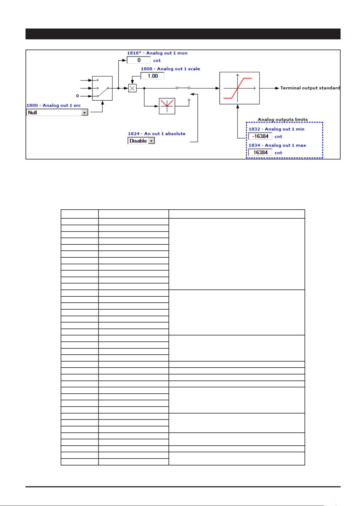
15 – ANALOG OUTPUTS
On the AVD regulation card there are two programmable analog outputs.
Analog output 1 supplies a two-pole +/-10VDC voltage signal, while analog output 2 can be programmed to obtain a
0-20mA or 4-20mA output signal in current or a signal in two-pole +/-10VDC voltage, depending on the parameter assigned.
Table: value of the signal of the analog outputs according to the measurement used
PAR Description Full scale output
626 Ramp ref out mon
628 Ramp setpoint
760 Ramp out mon
664 Speed setpoint
260 Motor speed
262 Motor speed nofilter
2150 Encoder 1 speed
852 Multi ref out mon
870 Mpot setpoint
894 Mpot output mon
920 Jog output mon
250 Output current
280 Torque current ref
282 Magnet current ref
284 Torque current
286 Magnet current
2360 Torque lim Pos Inuse
2362 Torque lim Neg Inuse
2386 Torque ref
2388 Torque ref nofilter
3070 Droop out mon
3104 Inertia comp mon
252 Output voltage 10V = 200% Mains voltage (Par 560)
254 Output frequency 10V = 1000Hz
270 DC link voltage 10V = 7000V
3006 Speed ratio out mon 10V = 100%
1500 Analog input 1 mon
1550 Analog input 2 mon
1600 Analog input 1X mon
1650 Analog input 2X mon
368 Drive overload accum
3260 Bres overload accum
2232 Spd reg P gain Inuse
2234 Spd reg I gain Inuse
3446 Powerloss nextratio 10V = 50%
4024 … 4174 Fieldbus M->SX mon
3700 … 3730 Pad X
10V = 200% CT drive rated current (available on Quick startup
manual, this value is defined @400Vac, default switching
10V = Full scale speed (Par 680)
frequency and 40°C)
10V = 200% Nominal motor torque
10V = 10V Analog input
5V = 100% Accumulator3212 Motor overload accum
10V = 400%
10V = 16384 * 2^16
ADV200 • Functions description and parameters list 73

Menu PAR Description UM Type FB BIT Def Min Max Acc Mod
0,5
15.1 1800 Analog out 1 src LINK 16/32 6000 0 16384 RW FVS
15.2 1802 Analog out 2 src LINK 16/32 6000 0 16384 RW FVS
Selection of the origin (source) of the signals that can be placed as variables on the analog outputs. The functions that can be assigned to the analog outputs are listed in the “L_ANOUT” selection list.
Menu PAR Description UM Type FB BIT Def Min Max Acc Mod
15.3 1808 Analog out 1 scale FLOAT 1.0 -10.0 10.0 RW FVS
15.4 1810 Analog out 2 scale FLOAT 1.0 -10.0 10.0 RW FVS
Parameter for setting a multiplier factor of the signal of the relative analog output. It can be used to amplify or
reduce the input value of the relative analog output block.
+10V
Par. 1808 (1810) =1
1
Par. 1808 (1810) =
2
1
2
Par. 1808 (1810)=-1
3
0V
-10V
Internal V
3
Stp Var x par. 1808 (1810)
Vout = 10 x ( )
FS Var
where:
Vout output voltage on the card terminals.
Stp Var actual value of the variable (variable unit)
SF Var full scale of the variable (variable unit)
Example of calculation of scale factor Analog out x scale
To display the drive speed, use an analog instrument with eld of measurement from 0...2V. This means that, to
display the speed of the drive, a voltage of 2V on the analog output of the drive must correspond to the maximum speed. With a scale factor equal to 1 a voltage of 10V would correspond to the maximum speed.
With a scale factor equal to 0.2 = 2V/10V a voltage of 2V would correspond to the maximum speed.
Menu PAR Description UM Type FB BIT Def Min Max Acc Mod
15.5 1816 Analog out 1 mon cnt INT16 0 0 0 ER FVS
The value of the actual voltage present on analog output 1 is displayed.
Menu PAR Description UM Type FB BIT Def Min Max Acc Mod
15.6 1818 Analog out 2 mon cnt INT16 0 0 0 ER FVS
The value of the actual voltage or current present on analog output 2 is displayed.
74 ADV200 • Functions description and parameters list

Menu PAR Description UM Type FB BIT Def Min Max Acc Mod
15.7 1824 An out 1 absolute ENUM Disable 0 1 ERW FVS
15.8 1826 An out 2 absolute ENUM Disable 0 1 ERW FVS
Enables the relative analog output as an absolute value. If this parameter is set to 1 the voltage on the analog
output assumes the value of 0 - 10V regardless of the sign of the command signal.
0 Disable
1 Enable
Menu PAR Description UM Type FB BIT Def Min Max Acc Mod
15.9 1832 Analog out 1 min cnt INT16 -16384 -32768 +32767 ERW FVS
15.10 1834 Analog out 1 max cnt INT16 16384 -32768 +32767 ERW FVS
Setting of the minimum and maximum values for the analog output for the voltage present on analog output 1
Menu PAR Description UM Type FB BIT Def Min Max Acc Mod
15.11 1840 Analog out 2 min cnt INT16 -16384 -32768 +32767 ERW FVS
15.12 1842 Analog out 2 max cnt INT16 16384 -32768 +32767 ERW FVS
Setting of the minimum and maximum values for the analog output for the voltage present on analog output 2
Menu PAR Description UM Type FB BIT Def Min Max Acc Mod
15.13 1848 Analog out 2 type ENUM -10V..+10V 0 2 ERW FVS
Selection of the type of output (in voltage or current). Depending on the output signal, move the S3 switch on
the regulation card. The standard output is coded for the signal in voltage.
0 0...20mA
1 4..20mA
2 -10V..+10V
If set to 0 the analog output sends 0...20mA
If set to 1 the analog output sends 4...20mA
If set to 2 the analog output sends -10..+10V
Menu PAR Description UM Type FB BIT Def Min Max Acc Mod
15.14 1850 Analog out 1X src LINK 16/32 6000 0 16384 RW FVS
15.15 1852 Analog out 2X src LINK 16/32 6000 0 16384 RW FVS
Selection of the origin (source) of the signals that can be placed as variables on the analog outputs of the expansion card. The functions that can be assigned to the analog outputs are listed in the “L_ANOUT” selection list.
ADV200 • Functions description and parameters list 75

Menu PAR Description UM Type FB BIT Def Min Max Acc Mod
0,5
15.16 1858 Analog out 1X scale FLOAT 1.0 -20.0 20.0 RW FVS
15.17 1860 Analog out 2X scale FLOAT 1.0 -20.0 20.0 RW FVS
Parameter for setting a multiplier factor of the signal of the relative analog output of the expansion card. It can
be used to amplify or reduce the input value of the relative analog output block.
+10V
Par.
1
2
1
2
3
1858 (1860)=1
Par. 1858 (1860) =
Par. 1858 (1860)=-1
0V
-10V
Stp Var x par. 1858 (1860)
Vout = 10 x ( )
FS Var
where:
Vout output voltage on the card terminals.
Stp Var actual value of the variable (variable unit)
SF Var full scale of the variable (variable unit)
Internal V
3
Example of calculation of the Analog out Xx scale factor
To display the drive speed, use an analog instrument with eld of measurement from 0 ... 2V. This means that,
to display the speed of the drive, a voltage of 2V on the analog output of the drive must correspond to the maxi-
mum speed. With a scale factor of 1 this would be 10V (Scale factor = 2V / 10 V = 0.200).
Menu PAR Description UM Type FB BIT Def Min Max Acc Mod
15.18 1866 Analog out 1X mon cnt INT16 0 0 0 ER FVS
The actual value of the voltage present on analog output 1 of the expansion card is displayed.
Menu PAR Description UM Type FB BIT Def Min Max Acc Mod
15.19 1868 Analog out 2X mon cnt INT16 0 0 0 ER FVS
The actual value of the voltage or current present on analog output 2 of the expansion card is displayed.
Menu PAR Description UM Type FB BIT Def Min Max Acc Mod
15.20 1874 An out 1X absolute ENUM Disable 0 1 ERW FVS
15.21 1876 An out 2X absolute ENUM Disable 0 1 ERW FVS
Enables the relative analog output as an absolute value. If this parameter is set to 1 the voltage on the analog
76 ADV200 • Functions description and parameters list

output assumes the value of 0 - 10V regardless of the sign of the command signal.
0 Disable
1 Enable
Menu PAR Description UM Type FB BIT Def Min Max Acc Mod
15.22 1882 Analog out 1X min cnt INT16 -16384 -32768 +32767 ERW FVS
15.23 1884 Analog out 1X max cnt INT16 16384 -32768 +32767 ERW FVS
Setting of the minimum and maximum values for the analog output for the voltage present on analog output 1
of the expansion card.
Menu PAR Description UM Type FB BIT Def Min Max Acc Mod
15.24 1886 Analog out 1X type ENUM - 0 3 ERW FVS
Selection of the programmed signal on analog output 1 of the expansion card. Depending on the output signal,
move the dedicated switch on the expansion card. The standard output is coded for the signal in voltage.
0 0...20mA
1 4..20mA
2 -10V..+10V
3 0..10V
If set to 0 the analog output sends 0...20mA
If set to 1 the analog output sends 4...20mA
If set to 2 the analog output sends -10..+10V
If set to 3 the analog output sends 0..+10V.
Menu PAR Description UM Type FB BIT Def Min Max Acc Mod
15.25 1890 Analog out 2X min cnt INT16 -16384 -32768 +32767 ERW FVS
15.26 1892 Analog out 2X max cnt INT16 16384 -32768 +32767 ERW FVS
Setting of the minimum and maximum values for the analog output in current or voltage present on analog
output 2 of the expansion card.
Menu PAR Description UM Type FB BIT Def Min Max Acc Mod
15.27 1898 Analog out 2X type ENUM -10V..+10V 0 3 ERW FVS
Selection of the programmed signal on analog output 2 of the expansion card. Depending on the output signal,
move the dedicated switch on the expansion card. The standard output is coded for the signal in voltage.
0 0...20mA
1 4..20mA
2 -10V..+10V
3 0..10V
If set to 0 the analog output sends 0...20mA
If set to 1 the analog output sends 4...20mA
If set to 2 the analog output sends -10..+10V
Menu PAR Description UM Type FB BIT Def Min Max Acc Mod
15.28 5460 Dig Analog out 0 ext INT16 16 0 -32768 32767 ERW FVS
15.29 5462 Dig Analog out 1 ext INT16 16 0 -32768 32767 ERW FVS
15.30 5464 Dig Analog out 2 ext INT16 16 0 -32768 32767 ERW FVS
15.31 5466 Dig Analog out 3 ext INT16 16 0 -32768 32767 ERW FVS
15.32 5468 Dig Analog out 4 ext INT16 16 0 -32768 32767 ERW FVS
15.33 5470 Dig Analog out 5 ext INT16 16 0 -32768 32767 ERW FVS
15.34 5472 Dig Analog out 6 ext INT16 16 0 -32768 32767 ERW FVS
ADV200 • Functions description and parameters list 77

15.35 5474 Dig Analog out 7 ext INT16 16 0 -32768 32767 ERW FVS
These parameters are used with I/O remotable module ( EXP-FL-XCAN-ADV expansion board is needed).
Analog output modules can have a resolution of 12 to 16 bits and scaling may vary from manufacturer to manufacturer.
E.g.:
12-bit module
Signal connected
Variant 1 Variant 2 Variant 3 Variant 4
Module configuration
-10V..+10V -2048..+2047 -32768..+32767 -16384..+16383
0V..+10V 0..+4095 0..+2047 0..+16383 0..+32767
4..20mA 0..+32767 +6553..+32767 +3276..+16383
16-bit module
Signal connected
Variant 1 Variant 2 Variant 3
Module configuration
-10V..+10V -32768..+32767
0V..+10V 0..+65535 0..+32767
4..20mA
There is no single unit that is suitable for all models of analog output module.
Check the scaling provided by the model being used and use the system variables accordingly.
Analog output 0 and analog output 1 can also be managed by the drive parameters.
To ensure correction operation, the scaling provided by the external module must be compatible with the scaling provided by the drive.
The drive supplies a datum for the I/O modules scaled as follows
Analog input type Range
-10V..+10V -32768..+32767
0V..+10V 0..+65535
4..20mA +13107..+65535
Analog outputs 0..1 are managed via drive parameters and the value produced by the drive overwrites that writ-
ten by the MDPLC or serial communication or eldbus.
1866 An out 1X mon sysEAO0Value
5460 Dig Analog out 0 ext
R
1868 An out 2X mon sysEAO1Value
5462 Dig Analog out 1 ext
R
R
5464 DigAnalog out 2 ext
W
R
5466 DigAnalog out 3 ext
W
R
5468 DigAnalog out 4 ext
W
R
5470 DigAnalog out 5 ext
W
R
W
R
W
sysExtIOAnaOut0
sysExtIOAnaOut 1
sysExtIOAnaOut 2
sysExtIOAnaOut 3
sysExtIOAnaOut 4
sysExtIOAnaOut 5
sysExtIOAnaOut 65472 DigAnalog out 6 ext
sysExtIOAnaOut 75474 DigAnalog out 7 ext
P
D
O
P
D
O
78 ADV200 • Functions description and parameters list

16 – MOTOR DATA
P.2006 P.2000 P.2002
P.2012
P.2006 P.2000 P.2002
P.2012
From this menu you can enter the motor plate data and “basic” values for the voltage/frequency characteristics. It is
important to enter the correct data in order to optimize drive operation and that of the application as a whole. These
data are required in order to obtain:
a) Computation of the normalization factors necessary for regulation
b) Computation of the estimated values for the motor parameters necessary for regulation
Rated voltage, Rated speed, Rated frequency, Rated current, Cos phi, Basic voltage and Basic frequency must be en-
tered (the Cos phi default value can be used if this value it not present on the plate). After entering these parameters,
send a Take motor par command to calculate (a) and (b) above. The motor cannot be enabled until the Take motor
par command has been set. If some results are inconsistent, or if the motor is much smaller than the inverter, an error
message is displayed indicating a numerical capacity overow and the previous set of parameters is restored in the
“Mot plate data” sub-menu.
Motor&Co.
Type: ABCDE
Motor: 3 phase
Rated voltage
Rated power
Rated speed (n )
IP54
Made in ..............
N
50 Hz
400 V
3kW
1420 rpm
IsoKlF
IEC 34-1/VDE 0530
Nr
.
I nom
Power factor
S1
12345-91
6.7A
0.8
Motor&Co.
Type: ABCDE
Motor: 3 phase
Rated voltage
Rated power
Rated speed (n )
IP54
Made in ..............
N
IsoKlF
60 Hz
575 V
2Hp
1750 rpm
IEC 34-1/VDE 0530
Nr
.
I nom
Power factor
Efficiency
S1
12345-91
2A
0.83
86.5
Motor data plates
Menu PAR Description UM Type FB BIT Def Min Max Acc Mod
16.1 2000 Rated voltage V FLOAT SIZE 50.0 690.0 RWZS FVS
Set the motor rated voltage as indicated on the data plate. This is the voltage the drive must supply
at the motor rated frequency.
Menu PAR Description UM Type FB BIT Def Min Max Acc Mod
16.2 2002 Rated current A FLOAT SIZE 0.3 2200.0 RWZS FVS
The motor rated current at its rated power (kW / Hp) and voltage (indicated on the motor data plate).
If using a single drive to control several motors connected in parallel (only possible in the V/f mode), enter a
value that corresponds to the sum of the rated currents of all the motors; in this case do not perform any selftuning operations.
Menu PAR Description UM Type FB BIT Def Min Max Acc Mod
16.3 2004 Rated speed rpm FLOAT SIZE 10.0 32000.0 RWZS FVS
Rated speed of the motor with full load in rpm (rpm = m-1). In some motors the synchronous speed (e.g. 1500
rpm for a 4-pole motor) and slippage, i.e. the loss of revolutions between the motor idling condition and the
rated load condition (e.g. 80 rpm), is indicated. Enter the following: synchronous speed - slippage.
Menu PAR Description UM Type FB BIT Def Min Max Acc Mod
16.4 2006 Rated frequency Hz FLOAT SIZE 10.0 1000.0 RWZS FVS
Rated frequency of the motor expressed in Hz, at which the ux weakening threshold starts.
ADV200 • Functions description and parameters list 79

Menu PAR Description UM Type FB BIT Def Min Max Acc Mod
16.5 2008 Pole pairs UINT16 SIZE 1 (*) RWZS FVS
Motor pole pairs. (*) Open loop (Sensorless) and Closed Loop = 20pp.
The number of motor pole pairs is calculated using the motor plate data and applying the following formula:
60 [s] x f [Hz]
P =
nN [rpm]
Where:
p = motor pole pairs
f = motor rated frequency (P. 2006)
nN = motor rated speed (P. 2004)
Menu PAR Description UM Type FB BIT Def Min Max Acc Mod
16.6 2010 Rated power kW FLOAT SIZE 0.05 2000.00 RWZS FVS
Rated power of the motor at the rated voltage and frequency. This value represents the mechanical power
produced on the motor shaft.
Menu PAR Description UM Type FB BIT Def Min Max Acc Mod
16.7 2012 Rated power factor FLOAT SIZE 0.6 0.95 RWZS FVS
Motor power factor, as indicated on the data plate (Cos j). This parameter is not always present on the motor
data plate: in that case use the default value present in the drive.
Menu PAR Description UM Type FB BIT Def Min Max Acc Mod
16.8 2020 Take parameters BIT 0 0 1 RWZ FVS
Saves the set motor data in the drive. This command must be supplied last after entering the appropriate
values of all the parameters listed above. This means calculating the normalization factors (a) and estimated
values for the motor parameters (b). The drive cannot be started until the Take parameters command has
been set.
Note ! This is not saved permanently. Use the “Save Parameters” command in the DRIVE CONFIG menu to save in the permanent
memory.
Menu PAR Description UM Type FB BIT Def Min Max Acc Mod
16.9 2022 Autotune rotation BIT 0 0 1 RWZ FVS
Performs self-tuning in rotation: the motor must be uncoupled from the load or the transmission must not represent more than 5% of the load. This procedure allows the greatest degree of accuracy in measuring the motor
parameters. To execute the command you must rst open the hardware enabling contact between terminals
7 and S3. Next set the Regulation mode parameter to Autotune. If you are not already in Local mode, press
the Local key (the
LOC
LED will light up) and close the hardware enabling contact again (terminals 7 and S3).
Selt-tuning can now be performed. At the end of the self-tuning procedure, open the contact between terminals
7 and S3 again and reset the parameters that were modied.
Menu PAR Description UM Type FB BIT Def Min Max Acc Mod
16.10 2024 Autotune still BIT 0 0 1 RWZ FVS
Performs self-tuning with the motor coupled to the transmission. The self-tuning procedure may cause limited
rotation of the motor shaft. To perform self-tuning, follow the procedure described for the previous parameter.
Menu PAR Description UM Type FB BIT Def Min Max Acc Mod
16.11 2026 Autotune mode ENUM Reduced 0 1 ERWZ FVS
Selection of the motor parameter self-tuning mode.
0 Reduced
1 Extended
80 ADV200 • Functions description and parameters list

If set to 0 all the motor parameters are measured except those relating to the non-linear saturation curve. Use
this mode to obtain a faster self-tuning procedure.
If set to 1 all the motor parameters are measured. Use this mode to obtain maximum efciency: this procedure
may take a few minutes.
Menu PAR Description UM Type FB BIT Def Min Max Acc Mod
16.12 2028 Take par status ENUM Required 0 0 R FVS
Indication of the status of parameter saving.
0 Required
1 Done
The parameter displays the Required message when the motor parameters that have been entered need to be
saved. When they have been saved the parameter indicates Done.
Menu PAR Description UM Type FB BIT Def Min Max Acc Mod
16.13 2030 Autotune status ENUM Required 0 0 R FVS
Indication of the status of execution of motor parameter self-tuning.
0 Required
1 Done
The parameter displays the Required message when motor parameter self-tuning is required. When self-tuning
is complete the parameter indicates Done.
Menu PAR Description UM Type FB BIT Def Min Max Acc Mod
16.14 2050 Measured Rs ohm FLOAT CALCF 0.0005 200.0 ERWS FVS
Measured stator resistance value.
Menu PAR Description UM Type FB BIT Def Min Max Acc Mod
16.15 2052 Measured DTL V FLOAT 0.0 0.0 100.0 ERWS FVS
Measured value of dead time compensation.
Menu PAR Description UM Type FB BIT Def Min Max Acc Mod
16.16 2054 Measured DTS V/A FLOAT 0.0 0.0 100.0 ERWS FVS
Measured compensation gradient value.
Menu PAR Description UM Type FB BIT Def Min Max Acc Mod
16.17 2056 Measured Lsig mH FLOAT CALCF 0.01 700.0 ERWS FVS
Measured leakage inductance value.
Menu PAR Description UM Type FB BIT Def Min Max Acc Mod
16.18 2058 Measured ImN A FLOAT CALCF 0.1 1000.0 ERWS FVS
Measured rated magnetizing current value.
Menu PAR Description UM Type FB BIT Def Min Max Acc Mod
16.19 2060 Measured ImX A FLOAT CALCF 0.0 0.0 ERWS FVS
Measured magnetizing current saturation value.
Menu PAR Description UM Type FB BIT Def Min Max Acc Mod
16.20 2062 Measured FlxN Wb FLOAT CALCF 0.05 10.0 ERWS FVS
Measured rated ux value.
ADV200 • Functions description and parameters list 81

Menu PAR Description UM Type FB BIT Def Min Max Acc Mod
16.21 2064 Measured FlxX Wb FLOAT CALCF 0.0 0.0 ERWS FVS
Measured ux saturation value.
Menu PAR Description UM Type FB BIT Def Min Max Acc Mod
16.22 2066 Measured P1 FLOAT 0.05 0.0 1.0 ERWS FVS
Measured value of the rst parameter to dene the motor magnetization curve.
Menu PAR Description UM Type FB BIT Def Min Max Acc Mod
16.23 2068 Measured P2 FLOAT 9.0 3.0 18.0 ERWS FVS
Measured value of the second parameter to dene the motor magnetization curve.
Menu PAR Description UM Type FB BIT Def Min Max Acc Mod
16.24 2070 Measured P3 FLOAT 0.87 0.0 1.0 ERWS FVS
Measured value of the third parameter to dene the motor magnetization curve.
Menu PAR Description UM Type FB BIT Def Min Max Acc Mod
16.25 2072 Measured Rr ohm FLOAT CALCF 0.0005 200.0 ERWS FVS
Measured rotor resistance value.
Menu PAR Description UM Type FB BIT Def Min Max Acc Mod
16.26 2078 Take tune parameters BIT 0 0 1 ERWZ FVS
Saves the motor data calculated by the self-tuning procedure in the drive.
Note ! Data are not saved permanently. Use the “Save Parameters” command in the DRIVE CONFIG menu to save in the permanent
memory.
82 ADV200 • Functions description and parameters list

17 – ENCODER
The closed-loop control mode requires a speed reading by a digital encoder on the motor shaft. The optional EXPENC card is necessary in order to acquire the encoder signals. Optional cards have been developed to acquire different types of encoder signals. These enable the drive to use both incremental and absolute signals as its feedback. The
natural variation in speed generated by machine load induction, known as slippage, can be compensated by the speed
feedback supplied by the encoder in V/f mode. In the eld oriented vector mode, closed-loop encoder feedback is essential for correct drive operation.
ADV200 • Functions description and parameters list 83

17.1 - ENCODER/ENCODER CONFIG
Menu PAR Description UM Type FB BIT Def Min Max Acc Mod
17.1.1 5310 Encoder sel src LINK 16 6000 0 16384 ERW FVS
Selection of the origin (source) of the input to be used to select the speed feedback encoder. The digital inputs
that can be used can be selected from the “L_DIGSEL2” selection list.
When the value of the signal is 0, it is associated with encoder 1.
When the value of the signal is 1, it is associated with encoder 2.
Menu PAR Description UM Type FB BIT Def Min Max Acc Mod
17.1.2 5314 Encoder sel mon UINT16 0 0 1 ER FVS
The encoder selected as the feedback device is displayed.
0 Encoder 1
1 Encoder 2
Menu PAR Description UM Type FB BIT Def Min Max Acc Mod
17.1.3 2172 SpdFbkLoss code UINT32 0 0 0 ER FVS
The Speed fbk loss alarm generated by an encoder fault is displayed. As each type of encoder generates the
alarm differently (incremental signal error, absolute signal error, serial error), this parameter displays information about the alarm that has occurred. If there are several, simultaneous causes, these are shown in this
parameter.
Bit Value Name
0 0x01 CHA
1 0x02 CHB
2 0x04 CHZ
3 0x08 MOD_INCR
4 0x10 MOD_ABS
5 0x20 CRC_CKS_P
6 0x40 ACK_TMO
7 0x80 DT1_ERR
8 0x100 Error Setup
10..15 Free
16..31 Depending on the type of feedback.
For further details please refer to the description of the Speed fbk loss alarm and the “9.2.1 Speed fbk loss
alarm according to the type of feedback” chapter of ADV200 QS manual.
Note ! To interpret the causes of the alarm correctly, you will need to convert the hexadecimal code written in parameter 17.29 SpdFb-
kLoss code, PAR 2172, into the corresponding binary code and then use the table of the encoder being used to check the various
active bits and relative description.
Example with Endat encoder:
PAR 2172 = A0H (hexadecimal value)
A0 is not present in the value column of the “ Speed fbk loss [22] with absolute EnDat encoder” table.
A0 must be seen as a bitword meaning A0 -> 10100000 -> bit 5 and bit 7. This indicates the simultaneous
intervention of the following causes:
Bit 5 = 20H Cause: disturbed SSI signals cause a CKS error or Parity
Bit 7 = 80H Cause: Encoder has detected malfunction and signals this to the drive via Error bit. Bits 16..31
contain the type of malfunction detected by the encoder.
84 ADV200 • Functions description and parameters list

17.2 - ENCODER/ENCODER 1
Menu PAR Description UM Type FB BIT Def Min Max Acc Mod
17.2.1 2100 Encoder 1 pulses ppr UINT16 CALCI CALCI CALCI RWZ FVS
Setting of the number of feedback encoder impulses.
Menu PAR Description UM Type FB BIT Def Min Max Acc Mod
17.2.2 2102 Encoder 1 supply V FLOAT 5.2 5.2 CALCF ERWZ FVS
Setting of the encoder supply voltage supplied by the relative optional card. Min and max values are modied
according to the type of encoder card applied.
Encoder option type Def Min Max
Enc1 EXP-DE-I1R1F2-ADV 5.2V 5.2V 20.0V
Enc2 EXP-SE-I1R1F2-ADV 5.2V 5.2V 6.0V
Enc3 EXP-SESC-I1R1F2-ADV 5.2V 5.2V 6.0V
Enc4 EXP-EN/SSI-I1R1F2-ADV 5.2V 5.2V 10.0V
Enc5 EXP-HIP-I1R1F2-ADV 8.0V 7.0V 12.0V
Enc6 EXP-RES-I1R1-ADV - - Enc7 EXP-DE-I2R1F2-ADV 5.2V 5.2V 20.0V
Enc8 EXP-ASC-I1-ADV 5.2V 5.2V 6.0V
Menu PAR Description UM Type FB BIT Def Min Max Acc Mod
17.2.3 2104 Encoder 1 input cfg ENUM TTL 0 1 ERWZ FVS
Setting of the input conguration of the incremental digital encoder, TTL or HTL.
0 HTL
1 TTL
The value of this parameter is automatically set in HTL when the value entered in the Encoder 1 supply parameter is more than 6.0V.
Menu PAR Description UM Type FB BIT Def Min Max Acc Mod
17.2.4 2106 Encoder 1 repetition ENUM No division 0 3 ERWZ FVS
Setting of the divider to apply to the encoder repetition output frequency.
0 No division
1 Divide 2
2 Divide 4
3 Divide 8
Menu PAR Description UM Type FB BIT Def Min Max Acc Mod
17.2.5 2108 Encoder 1 signal Vpp V FLOAT 1.0 0.8 1.2 ERWZ FVS
Setting of the encoder 1 signal peak-to-peak voltage value. Incremental sinusoidal encoders and absolute
SinCos encoders normally produce signals with a peak-to-peak voltage of 1 Vpp. Due to voltage drops along
the cable, the signal may have a lower peak-to-peak voltage when it reaches the feedback card, triggering the
Speed fbk loss alarm.
This parameter is used to congure the value of the peak-to-peak voltage of the incremental sinusoidal encoders and absolute SinCos encoders on the input terminals of the feedback card.
Menu PAR Description UM Type FB BIT Def Min Max Acc Mod
17.2.6 2110 Encoder1signal check ENUM Check A-B 0 1 ERWZ FVS
Conguration of which channels of the incremental digital encoder 1 must be controlled for processing the
Speed fbk loss [22].
0 Check disabled
1 Check A-B
ADV200 • Functions description and parameters list 85

2 Check A-B-Z
4 Check A-B-SE
If set to 1, the application checks for the presence of the signals of channels A-B
If set to 2, the application checks for the presence of the signals of channels A-B-Z
If set to 4, the application controls loss of feedback for SE (single ended) encoders.
If the application detects the absence of feedback the Speed fbk loss [22] is generated.
As loss of feedback cannot be detected at speeds of around zero, the control is only performed if the speed reference is higher than the value set in parameter 4564 SpdFbkLoss threshold. It is also important to consider
the fact that when working with a speed reference slightly above the limit set in parameter 4564 SpdFbkLoss
threshold, the speed error could exceed the set threshold, given the load or current limit, and generate false
alarms.
In that case increase the value of parameter 4550 SpdRefLoss threshold or of parameter 4554 SpdRefLoss holdoff.
Menu PAR Description UM Type FB BIT Def Min Max Acc Mod
17.2.7 2112 Encoder 1 SSI clocks UINT16 13 11 25 ERWZ F_S
Setting of the length of the serial package of the SSI encoder 1 used. The value is shown on the encoder data-
sheet and dened in clock cycles (usually from 13 to 25 bits).
Example of single-turn encoder
13 position bits: set par 2114 = 13.
13 clock bits: set par 2112 = 13.
Example of multi-turn encoder
13 position bits: set par 2114 = 13.
25 clock bits: set par 2112 = 25.
Menu PAR Description UM Type FB BIT Def Min Max Acc Mod
17.2.8 2114 Encoder1SSI pos bits UINT16 13 11 25 ERWZ F_S
Setting of the number of bits used by the SSI encoder 1 to dene the position.
See examples of PAR 2112.
Menu PAR Description UM Type FB BIT Def Min Max Acc Mod
17.2.9 2182 Encoder1 ENDAT clock ENUM 1 MHz 0 1 ERWZ FVS
Selection of clock value for Encoder 1 ENDAT type.
0 1 MHz
1 500 kHz
Menu PAR Description UM Type FB BIT Def Min Max Acc Mod
17.2.10 2130 Encoder 1 direction ENUM Not inverted 0 1 RWZ FVS
Selection of the encoder direction
0 Not inverted
1 Inverted
By setting 0 the encoder feedback signals are not inverted.
By setting 1 the encoder feedback signals are inverted.
Menu PAR Description UM Type FB BIT Def Min Max Acc Mod
17.2.11 2132 Encoder 1 mode ENUM None CALCI CALCI ERWZ FVS
Setting of the method for measuring the speed of the encoder connected to the optional card. The drive automatically recognises the encoder card that is inserted and only shows the methods that are compatible.
0 None
1 Digital FP
86 ADV200 • Functions description and parameters list

2 Digital F
3 Sinus
4 Sinus SINCOS
5 Sinus ENDAT
6 Sinus SSI
7 Sinus HIPER
8 Resolver
9 Abs SINCOS
10 ENDAT
11 SSI
The speed measurement procedure depends on the type of encoder card; minimum and maximum default
values are set according to the type of feedback card that is applied.
Encoder option type Def Min Max
Enc 1 Digital F Digital FP Digital F
Enc 2 Sinus Sinus Sinus
Enc 3 Sinus SINCOS Sinus SINCOS Sinus SINCOS
Enc 4 Sinus SSI Sinus ENDAT SSI
Enc 5 Sinus HIPER Sinus HIPER Sinus HIPER
Enc 6 Resolver Resolver Resolver
Enc 7 Digital F Digital FP Digital F
Enc 8 SINCOS / No inc dig SINCOS / No inc dig SINCOS / No inc dig
In the presence of the Enc 1 encoder option:
• setting 1 (Digital FP) selects the method for measuring frequency and period. This type of measurement
lets you achieve high precision and dynamics at medium and high speed.
• setting 2 (Digital F) selects the method for measuring frequency. This selection is preferable for applica-
tions that rotate at very low speeds.
In the presence of the Enc 4 encoder option:
• selection 10 (ENDAT), as opposed to selection 5 (Sinusoidal ENDAT), indicates that the encoder has no
incremental channels. Switching between the two selections is automatic by means of a recognition procedure.
• selection 11 (SSI), as opposed to selection 6 (Sinusoidal SSI), indicates that the encoder has no incremen-
tal channels. Switching between the two selections has to be performed manually during commissioning.
Menu PAR Description UM Type FB BIT Def Min Max Acc Mod
17.2.12 2134 Encoder1speed filter ms FLOAT 2.000 0.125 20.000 ERW FVS
Setting of the time constant of the lter applied to the feedback encoder pulse reading. The parameter affects
both the accuracy of the speed measurement and the dynamics obtainable in closed loop control. Long updat-
ing times allow greater stability (more ltering) of the speed measurement, as a higher number of encoder
pulses are counted at a given speed of rotation. On the other hand, the use of a speed measurement lter
introduces delays that do not permit high control loop dynamics. Low settings extend the regulation bandwidth
but may accentuate any disturbance.
Menu PAR Description UM Type FB BIT Def Min Max Acc Mod
17.2.13 2150 Encoder 1 speed rpm INT16 16/32 0 0 0 ER FVS
The motor speed measured by the encoder is displayed.
Menu PAR Description UM Type FB BIT Def Min Max Acc Mod
17.2.14 2162 Encoder 1 position cnt UINT16 16 0 0 0 ER FVS
The encoder position is displayed. The scale is Number of encoder impulses *4.
Menu PAR Description UM Type FB BIT Def Min Max Acc Mod
17.2.15 5350 Encoder 1 state UINT16 0 0 0 ER FVS
Indicates the state of Encoder 1 (1= error, 0 = no error) regardless of whether this Encoder is used/not used as
feedback for motor control.
ADV200 • Functions description and parameters list 87

Menu PAR Description UM Type FB BIT Def Min Max Acc Mod
17.2.16 5352 Encoder 1 err code UINT32 0 0 0 ER FVS
This parameter contains a hexadecimal code that supplies information on the type of error that occurred.
Error values are the same (and have the same signicance) as the ones indicated in parameter IPA 2172 SpdFbkLoss code.
17.3 - ENCODER/ENCODER 2
Menu PAR Description UM Type FB BIT Def Min Max Acc Mod
17.3.1 5100 Encoder 2 pulses ppr UINT16 CALCI CALCI CALCI ERWZ FVS
Setting of the number of impulses/rev of the incremental encoder mounted in slot 1 or 3.
Menu PAR Description UM Type FB BIT Def Min Max Acc Mod
17.3.2 5102 Encoder 2 supply V FLOAT 5.2 5.2 CALCF ERWZ FVS
Setting of the encoder supply voltage supplied by the relative optional card. Min and max values refer to the
incremental digital encoder cards with one or two encoders.
Menu PAR Description UM Type FB BIT Def Min Max Acc Mod
17.3.3 5104 Encoder 2 input cfg ENUM TTL 0 1 ERWZ FVS
Setting of the input conguration of the incremental digital encoder, TTL or HTL.
0 HTL
1 TTL
The value of this parameter is automatically set in HTL when the value entered in the Encoder 2 supply parameter is more than 6.0V.
Menu PAR Description UM Type FB BIT Def Min Max Acc Mod
17.3.4 5106 Encoder 2 repetition ENUM
No division
0 3 ERWZ FVS
Setting of the divider to apply to the encoder repetition output frequency.
0 No division
1 Divide 2
2 Divide 4
3 Divide 8
Menu PAR Description UM Type FB BIT Def Min Max Acc Mod
17.3.5 5108 Encoder 2 signal Vpp V FLOAT 1.0 0.8 1.2 ERWZ FVS
Setting of the encoder 2 signal peak-to-peak voltage value. Incremental sinusoidal encoders and absolute
SinCos encoders normally produce signals with a peak-to-peak voltage of 1 Vpp. Due to voltage drops along
the cable, the signal may have a lower peak-to-peak voltage when it reaches the feedback card, triggering the
Speed fbk loss alarm.
This parameter is used to congure the value of the peak-to-peak voltage of the incremental sinusoidal encoders and absolute SinCos encoders on the input terminals of the feedback card.
Menu PAR Description UM Type FB BIT Def Min Max Acc Mod
17.3.6 5110 Encoder2signal check ENUM Contr A-B 0 3 ERWZ FVS
Conguration of which channels of the incremental digital encoder 2 must be controlled for processing the
Speed fbk loss [22].
0 Check disabled
1 Check A-B
2 Check A-B-Z
4 Check A-B-SE
88 ADV200 • Functions description and parameters list

If set to 1, the application checks for the presence of the signals of channels A-B
If set to 2, the application checks for the presence of the signals of channels A-B-Z
If set to 4, the application controls loss of feedback for SE (single ended) encoders.
If the application detects the absence of feedback the Speed fbk loss [22] is generated.
As loss of feedback cannot be detected at speeds of around zero, the control is only performed if the speed reference is higher than the value set in parameter 4564 SpdFbkLoss threshold. It is also important to consider
the fact that when working with a speed reference slightly above the limit set in parameter 4564 SpdFbkLoss
threshold, the speed error could exceed the set threshold, given the load or current limit, and generate false
alarms.
In that case increase the value of parameter 4550 SpdRefLoss threshold or of parameter 4554 SpdRefLoss
holdoff.
Menu PAR Description UM Type FB BIT Def Min Max Acc Mod
17.3.7 5112 Encoder 2 SSI clocks UINT16 13 11 25 ERWZ FVS
Setting of the length of the serial package of the SSI encoder 2 used. The value is shown on the encoder data-
sheet and dened in clock cycles (usually from 13 to 25 bits).
Example of single-turn encoder
13 position bits: set par 5114 = 13.
13 clock bits: set par 5112 = 13.
Example of multi-turn encoder
13 position bits: set par 5114 = 13.
25 clock bits: set par 5112 = 25.
Menu PAR Description UM Type FB BIT Def Min Max Acc Mod
17.3.8 5114 Encoder2SSI pos bits UINT16 13 11 25 ERWZ FVS
Setting of the number of bits used by the SSI encoder 2 to dene the position.
See examples of PAR 5112.
Menu PAR Description UM Type FB BIT Def Min Max Acc Mod
17.3.9 5182 Encoder2 ENDAT clock ENUM 1 MHz 0 1 ERWZ FVS
Selection of clock value for Encoder 2 ENDAT type.
0 1 MHz
1 500 kHz
Menu PAR Description UM Type FB BIT Def Min Max Acc Mod
17.3.10 5130 Encoder 2 direction ENUM Not inverted 0 1 ERWZ FVS
Selection of the encoder direction
0 Not inverted
1 Inverted
If set to 0 the encoder feedback signals are not inverted.
If set to 1 the encoder feedback signals are inverted.
Menu PAR Description UM Type FB BIT Def Min Max Acc Mod
17.3.11 5132 Encoder 2 mode ENUM None CALCI CALCI ERWZ FVS
Setting of the method for measuring the speed of the digital encoder connected to the optional card.
0 Nessuna
1 Digital FP
2 Digital F
3 Sinus
4 Sinus SINCOS
5 Sinus ENDAT
ADV200 • Functions description and parameters list 89

6 Sinus SSI
7 Sinus HIPER
8 Resolver
9 Abs SINCOS
10 ENDAT
11 SSI
In the presence of the Enc 1 encoder option:
• setting 1 (Digital FP) selects the method for measuring frequency and period. This selection is preferable
for applications that rotate at very low speeds.
• setting 2 (Digital F) selects the method for measuring frequency. This type of measurement lets you
achieve high precision and dynamics at medium and high speed.
In the presence of the Enc 4 encoder option:
• selection 10 (ENDAT), as opposed to selection 5 (Sinusoidal ENDAT), indicates that the encoder has no
incremental channels. Switching between the two selections is automatic by means of a recognition procedure.
• selection 11 (SSI), as opposed to selection 6 (Sinusoidal SSI), indicates that the encoder has no incremen-
tal channels. Switching between the two selections has to be performed manually during commissioning.
The other settings are relative to the type of encoder used.
Menu PAR Description UM Type FB BIT Def Min Max Acc Mod
17.3.12 5134 Encoder2speed filter ms FLOAT 2.000 0.125 20.000 ERW FVS
Setting of the time constant of the lter applied to the reading of the feedback encoder impulses. The parameter affects both the precision of the speed measurement and the dynamics obtainable in the closed-loop
control mode. Long update times provide greater stability (increased ltering) of speed measurement, as more
encoder impulses are counted at a given speed of rotation. On the other hand, the speed measurement lter
adds delays that prevent high control loop dynamics. Low settings increase the regulation bandwidth but could
accentuate disturbance.
Menu PAR Description UM Type FB BIT Def Min Max Acc Mod
17.3.13 5150 Encoder 2 speed rpm INT16 16/32BIT 0 0 0 ER FVS
The speed measured for encoder 2 is displayed.
Menu PAR Description UM Type FB BIT Def Min Max Acc Mod
17.3.14 5162 Encoder 2 position cnt UINT16 16 0 0 0 ER FVS
The encoder position is displayed. The scaling factor is Number encoder impulses *4.
Menu PAR Description UM Type FB BIT Def Min Max Acc Mod
17.3.15 5360 Encoder 2 state UINT16 0 0 0 ER FVS
Indicates the state of Encoder 2 (1= error, 0 = no error) regardless of whether this Encoder is used/not used as
feedback for motor control.
Menu PAR Description UM Type FB BIT Def Min Max Acc Mod
17.3.16 5362 Encoder 2 err code UINT32 0 0 0 ER FVS
This parameter contains a hexadecimal code that supplies information on the type of error that occurred.
Error values are the same (and have the same signicance) as the ones indicated in parameter IPA 2172 SpdFbkLoss code.
90 ADV200 • Functions description and parameters list

17.4 - ENCODER/ENCODER 3
Menu PAR Description UM Type FB BIT Def Min Max Acc Mod
17.4.1 5200 Encoder 3 pulses ppr UINT16 1024 128 32768 ERWZ FVS
Setting of the number of impulses/rev of the incremental encoder mounted in slot 1 or 3.
Menu PAR Description UM Type FB BIT Def Min Max Acc Mod
17.4.2 5204 Encoder 3 input cfg ENUM TTL 0 1 ERWZ FVS
Setting of the input conguration of incremental digital encoder 3, TTL or HTL. If the encoder has an internal
power supply the level of the encoder’s supply voltage is equal to that set for encoder 2.
0 HTL
1 TTL
The value of this parameter is automatically set in HTL when the value entered in the Encoder 2 supply parameter is more than 6.0V.
Menu PAR Description UM Type FB BIT Def Min Max Acc Mod
17.4.3 5210 Encoder3signal check ENUM Check A-B 0 3 ERWZ FVS
Conguration of which channels of the incremental digital encoder 3 must be controlled for processing the
Speed fbk loss [22].
0 Check disabled
1 Check A-B
2 Check A-B-Z
4 Check A-B-SE
If set to 1, the application checks for the presence of the signals of channels A-B
If set to 2, the application checks for the presence of the signals of channels A-B-Z
If set to 4, the application controls loss of feedback for SE (single ended) encoders.
If the application detects the absence of feedback the Speed fbk loss [22] is generated.
As loss of feedback cannot be detected at speeds of around zero, the control is only performed if the speed reference is higher than the value set in parameter 4564 SpdFbkLoss threshold. It is also important to consider
the fact that when working with a speed reference slightly above the limit set in parameter 4564 SpdFbkLoss
threshold, the speed error could exceed the set threshold, given the load or current limit, and generate false
alarms.
In that case increase the value of parameter 4550 SpdRefLoss threshold or of PAR 4554 SpdRefLoss holdoff.
Menu PAR Description UM Type FB BIT Def Min Max Acc Mod
17.4.4 5230 Encoder 3 direction ENUM Not inverted 0 1 ERWZ FVS
Selection of the encoder direction
0 Not inverted
1 Inverted
If set to 0 the encoder feedback signals are not inverted.
If set to 1 the encoder feedback signals are inverted.
Menu PAR Description UM Type FB BIT Def Min Max Acc Mod
17.4.5 5262 Encoder 3 position cnt UINT16 16 0 0 0 ER FVS
The encoder position is displayed. The scaling factor is Number encoder impulses *4.
Menu PAR Description UM Type FB BIT Def Min Max Acc Mod
17.4.6 5370 Encoder 3 state UINT16 0 0 0 ER FVS
ADV200 • Functions description and parameters list 91

Indicates the state of Encoder 3 (1= error, 0 = no error) regardless of whether this Encoder is used/not used as
feedback for motor control.
Menu PAR Description UM Type FB BIT Def Min Max Acc Mod
17.4.7 5372 Encoder 3 err code UINT32 0 0 0 ER FVS
This parameter contains a hexadecimal code that supplies information on the type of error that occurred.
Error values are the same (and have the same signicance) as the ones indicated in parameter IPA 2172 SpdFbkLoss code.
17.5 - ENCODER/RESOLVER
Menu PAR Description UM Type FB BIT Def Min Max Acc Mod
17.5.1 2116 Resolver pole pairs UINT16 1 1 8 ERWZ FVS
Setting of pairs of poles of resolver used (see resolver plate data).
1 1 pair of poles
2 2 pairs of poles
...
Menu PAR Description UM Type FB BIT Def Min Max Acc Mod
17.5.2 2118 Resolver frequency Hz UINT16 8000 2000.0 10000.0 ERWZ FVS
Value of the resolver frequency (see Resover name plate data). Step 250Hz.
Nota! In order to manage the EXP-RES-I1R1-ADV card, three parameters need to be set: PAR 2118, 2120 and 2116.
Parameters PAR 2124 and 2128 could be modify if it is require a fine tuning of the card and resolver output voltage are outside the
limits.
Plese refer to EXP-RES-I1R1-ADV Resolver option card instruction book (code 1S5F33) for more detailed informations
Menu PAR Description UM Type FB BIT Def Min Max Acc Mod
17.5.3 2120 Resolver T ratio K FLOAT 0.5 0.2 1.0 ERWZ FVS
Value of the resolver Trasformer ratio of used resolver (see Resolver name plate data).
Menu PAR Description UM Type FB BIT Def Min Max Acc Mod
17.5.4 2122 Resolver repetition ENUM 16384 ppr 0 3 ERWZ FVS
Simulated selection of the resolver repetition.
0 256 ppr
1 1024 ppr
2 4096 ppr
3 16384 ppr
Menu PAR Description UM Type FB BIT Def Min Max Acc Mod
17.5.5 2124 Resolver LOS thr V FLOAT 2.200 0.000 4.820 ERWZ FVS
Loss Of Signal threshold: Setting of the lower threshold value of the Resolver signal. Values below this setting
will generate a Speed fbk loss [22] alarm.
Menu PAR Description UM Type FB BIT Def Min Max Acc Mod
17.5.6 2128 Resolver MIS thr V FLOAT 0.380 0.000 4.820 ERWZ FVS
A threshold value between SIN and COS signal amplitudes can be set.
An alarm is shown If it is detected an amplitude value differences higher than the value set in MIS threshold.
This value can be increased: If the alarm does not disappear, the resolver used could be defective or the wiring
drive-resolver are not correct.
92 ADV200 • Functions description and parameters list

Menu PAR Description UM Type FB BIT Def Min Max Acc Mod
17.5.7 2094 Resolver freeze0 src LINK 16 6000 0 16384 ERWZ FVS
17.5.8 2096 Resolver freeze1 src LINK 16 6000 0 16384 ERWZ FVS
It indicates which digital input can be used as Freeze input 0 or Freeze input 1 when resolver feedback is
used and managed thru MDPLC application. Digital input is updated every 125 μsec.
Input can be selected from those available on “L_RESFREEZE” selection list.
ADV200 • Functions description and parameters list 93

18 – SPEED REG GAINS
The speed adaptive allows different speed regulator gains to be obtained according to the speed or another value. The
behaviour of the speed regulator can thus be congured in the best way for the specic application requirements.
Note ! Current, flux and voltage regulators can be set using the self-tuning procedure. If this is not successful, current and flux regulators
can be tuned manually (this does not apply to voltage regulators, whch must not be modified by the user). The speed regulator
must be tuned manually. Gains are usually adjusted according to the drive speed.
Menu PAR Description UM Type FB BIT Def Min Max Acc Mod
18.1 2200 Speed reg P1 gain perc INT16 100 0 1000 RW F_S
18.2 2202 Speed reg I1 time perc INT16 100 0 1000 RW F_S
Setting of the proportional and integral gain of the speed regulator, set 1.
Menu PAR Description UM Type FB BIT Def Min Max Acc Mod
18.3 2204 Speed reg P2 gain perc INT16 100 0 1000 ERW F_S
18.4 2206 Speed reg I2 time perc INT16 100 0 1000 ERW F_S
Setting of the proportional and integral gain of the speed regulator, set 2.
Menu PAR Description UM Type FB BIT Def Min Max Acc Mod
18.5 2216 Gain adapt src LINK 16/32 664 0 16384 ERW F_S
Selection of the origin (source) of the signal to be used for the adaptive speed gain. The values that can be associated with the function are listed in the “L_REF” selection list.
Menu PAR Description UM Type FB BIT Def Min Max Acc Mod
18.6 2218 Gain adapt spd thr 1_2 perc FLOAT 0.0 0.0 100.0 ERW F_S
Setting of the speed threshold for changing gains from set 1 to set 2.
94 ADV200 • Functions description and parameters list

Menu PAR Description UM Type FB BIT Def Min Max Acc Mod
18.7 2220 Gain adapt spd band 1_2 perc FLOAT 0.0 0.0 100.0 ERW F_S
Setting of the band within which gains vary between set 1 and set 2. The use of this parameter ensures a
smooth transition between the two parameter sets.
Menu PAR Description UM Type FB BIT Def Min Max Acc Mod
18.8 2226 Gain 0 enable ENUM Disable 0 1 ERW F_S
Enabling of the gain at zero speed.
0 Disable
1 Enable
When this parameter is set to 0 the control of gains at zero speed is disabled.
When this parameter is set to 1 the control of gains at zero speed is enabled. This function is used to improve
the response of the motor below the zero speed threshold (Speed zero threshold)..
Menu PAR Description UM Type FB BIT Def Min Max Acc Mod
18.9 2228 Speed reg P0 gain perc INT16 100 0 1000 ERW F_S
Setting of the proportional gain of the speed regulator at zero speed.
Menu PAR Description UM Type FB BIT Def Min Max Acc Mod
18.10 2230 Speed reg I0 gain perc INT16 100 0 1000 ERW F_S
Setting of the integral gain of the speed regulator at zero speed.
Menu PAR Description UM Type FB BIT Def Min Max Acc Mod
18.11 2232 Spd reg P gain Inuse perc INT16 16/32 100 0 1000 ER F_S
The current proportional coefcient of the speed regulator is displayed as a percentage.
Menu PAR Description UM Type FB BIT Def Min Max Acc Mod
18.12 2234 Spd reg I gain Inuse perc INT16 16/32 100 0 1000 ER F_S
The current integral coefcient of the speed regulator is displayed as a percentage.
Menu PAR Description UM Type FB BIT Def Min Max Acc Mod
18.13 2236 Speed reg P gain N/rpm FLOAT CALCF 0.0 500.0 ERWS F_S
Setting of the proportional coefcient of the speed regulator.
Menu PAR Description UM Type FB BIT Def Min Max Acc Mod
18.14 2238 Speed reg I time ms FLOAT CALCF 1.0 5000.0 ERWS F_S
Setting of the integral coefcient of the speed regulator.
ADV200 • Functions description and parameters list 95

Menu PAR Description UM Type FB BIT Def Min Max Acc Mod
18.15 2244 Speed reg I dis src LINK 16/32 6000 0 16384 ERW F_S
Selection of the origin (source) of the signal for Enabling/disabling of the Integral part of the Speed regulator (Null=
enabled). The signal to be associated with this function can be selected from the “L_DIGSEL2” selection list.
Menu PAR Description UM Type FB BIT Def Min Max Acc Mod
18.16 2246 Speed reg P factor perc FLOAT 16/32 0 0 0 ER F_S
Monitor of the proportional component value of the Speed regulator output. It is also available thru analog
output.
Menu PAR Description UM Type FB BIT Def Min Max Acc Mod
18.17 2248 Speed reg I factor perc FLOAT 16/32 0 0 0 ER F_S
Monitor of the integral component value of the Speed regulator output. It is also available thru analog output.
Menu PAR Description UM Type FB BIT Def Min Max Acc Mod
18.18 2240 Inertia kgm2 FLOAT SIZE 0.001 100.0 RWZS F_S
Setting of total inertia of the application with reference to the motor shaft.
Inertia is the tendency of a body at rest to remain at rest or of a body in straight line motion to stay in motion in astraight line unless acted on by an outside force;
Setting the total system inertia value (motor + mechanical transmission), the drive will set automatically the
PAR 2236 Speed reg P gain proportional gain of the speed regulator in order to react immediatelly to the
speed variations.
Menu PAR Description UM Type FB BIT Def Min Max Acc Mod
18.19 2242 Bandwidth rad/s FLOAT SIZE 1.0 500.0 RWZS F_S
Setting of the bandwidth.
The bandwidth denes the dynamic performance in terms of capacity of follow the speed references or torque
which the are time variable .
Increasing the value, the drive responce time will increase (automatically will increase PAR 2236 Speed reg P
gain and decrease PAR 2238 Speed reg I time).
Higher value can be used in the case of “rigid” connections between the motor and the machine. Otherwise
you may encounter instability of the system.
96 ADV200 • Functions description and parameters list
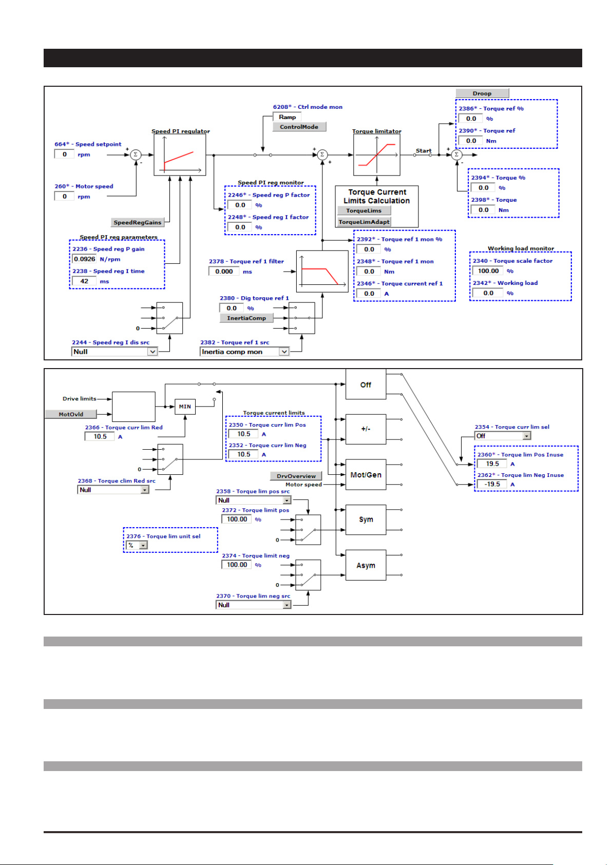
19 – REGULATOR PARAM
Menu PAR Description UM Type FB BIT Def Min Max Acc Mod
19.1 2250 Current reg P gain V/A FLOAT CALCF 0.0 0.0 ERWS F_S
Setting of the proportional coefcient of the current regulator.
Menu PAR Description UM Type FB BIT Def Min Max Acc Mod
19.2 2252 Current reg I time ms FLOAT CALCF 0.01 10000.0 ERWS F_S
Setting of the integral coefcient of the current regulator.
Menu PAR Description UM Type FB BIT Def Min Max Acc Mod
19.3 2260 Flux reg P gain A/Wb FLOAT CALCF 0.0 0.0 ERWS F__
Setting of the proportional coefcient of the ux regulator.
ADV200 • Functions description and parameters list 97

Menu PAR Description UM Type FB BIT Def Min Max Acc Mod
19.4 2262 Flux reg I time ms FLOAT CALCF 0.01 10000.0 ERWS F__
Setting of the integral coefcient of the ux regulator.
Menu PAR Description UM Type FB BIT Def Min Max Acc Mod
19.5 2264 Flux reg P gain OL A/Wb FLOAT CALCF 0.0 0.0 ERWS __S
Setting of the ux regulator proportional gain when the drive is used in Flux vector OL control mode. This parameter is set automatically by the self-tuning procedure.
Menu PAR Description UM Type FB BIT Def Min Max Acc Mod
19.6 2266 Flux reg I time OL ms FLOAT CALCF 0.01 10000.0 ERWS __S
Setting of the ux regulator integral time when the drive is used in Flux vector OL control mode. This parameter
is set automatically by the self-tuning procedure.
Menu PAR Description UM Type FB BIT Def Min Max Acc Mod
19.7 2270 Voltage reg P gain Wb/V FLOAT CALCF 0.0 0.0 ERWS F_S
Setting of the proportional coefcient of the voltage regulator.
Menu PAR Description UM Type FB BIT Def Min Max Acc Mod
19.8 2272 Voltage reg I time s FLOAT CALCF 0.1 100.0 ERWS F_S
Setting of the integral coefcient of the voltage regulator.
Dead time compensation
Output voltage
Dead time slope
Voltage command to PWM
Dead time limit
The dead time compensation function (Dead time compensation), compensates the distortion of output voltage caused by the voltage drop on the IGBT devices and their switching characteristics.
Distortion of output voltage could cause irregular motor rotation.
Menu PAR Description UM Type FB BIT Def Min Max Acc Mod
19.9 2280 Dead time limit V FLOAT SIZE 0.0 50.0 ERWS FVS
Setting of the dead time voltage compensation value.
Menu PAR Description UM Type FB BIT Def Min Max Acc Mod
19.10 2282 Dead time slope V/A FLOAT SIZE 0.0 200.0 ERWS FVS
Setting of the dead time compensation slope value.
Menu PAR Description UM Type FB BIT Def Min Max Acc Mod
19.11 2290 Voltage base V FLOAT CALCF 50.0 690.0 ERWS F_S
Setting of the voltage value that determines the threshold at which ux weakening starts (maximum drive output voltage). If this parameter is set to a value equal to the nominal speed of the motor, operation is at nominal
ux in the constant torque region and weakened ux at higher frequencies. The default value is set to the volt-
age supply value.
98 ADV200 • Functions description and parameters list

Menu PAR Description UM Type FB BIT Def Min Max Acc Mod
19.12 2292 Voltage margin perc FLOAT 5.0 0.0 10.0 ERWS F_S
Setting of the voltage regulation margin according to the available voltage. In case of a Voltage base setting
close to or equal to the actual mains value, Voltage margin represents the margin allowable by the voltage
regulation to perform rapid current variations when load steps are suddenly applied.
A value of 5% allows a very fast response to load steps but with a loss of output voltage and thus power output
(reduced power output).
The minimum value (1%) allows a maximum output voltage (around 98%) of the mains voltage to be achieved
but with loss of quality of the dynamic response.
Menu PAR Description UM Type FB BIT Def Min Max Acc Mod
19.13 2300 Minimum speed OL rpm INT16 30 0 CALCI ERW __S
Setting of the minimum speed threshold in the Flux vector OL control mode. Below this limit the sensorless
regulator is disabled.
Menu PAR Description UM Type FB BIT Def Min Max Acc Mod
19.14 2302 Min speed delay OL ms UINT16 200 0 5000 ERW __S
Setting of the delay for disabling the sensorless regulator.
Menu PAR Description UM Type FB BIT Def Min Max Acc Mod
19.15 2304 Speed filter OL ms FLOAT 5.0 0.1 20.0 ERWZ __S
Setting of the time constant for the estimated speed in Flux vector OL mode. By increasing this parameter it
is possible to reduce the level of disturbance of the estimated speed, but the speed control dynamics are also
lowered.
Menu PAR Description UM Type FB BIT Def Min Max Acc Mod
19.16 2306 Flux observ gainH OL FLOAT 250.0 10.0 5000.0 ERW __S
Gain value of the Flux observer at the high frequency/speed (Flux vector OL control mode).
Note! Frequency value set in IPA2322 must be higher than the value set in IPA2324 (without sign). All the Flux gain values between the
two frequency are obtained through linear interpolation.
The default gain value set at the low frequncy (IPA 2316) should guarantee smooth operation for all motor power sizes.
For any possible issues during the speed starting phase is possible to improve the response of the motor by changing the value of
the gain. Normally high gain values guarantee more stability, but could lead to errors on estimation Torque value.
The gain at high frequency (IPA 2306) must be changed if speed fluctuations at high rpm are shown.
By increasing the gain value it is possible to get better performance, however, too high values could lead to instability of the mo-
tor speed control.
Menu PAR Description UM Type FB BIT Def Min Max Acc Mod
19.17 2322 Freq observ gainH OL rad/s FLOAT 50.0 0.0 5000.0 ERW __S
Frequency value above which applies the gain of the Flux observer at the high frequency (Flux vector OL con-
trol mode).
Menu PAR Description UM Type FB BIT Def Min Max Acc Mod
19.18 2316 Flux observ gainL OL FLOAT 100.0 0.0 5000.0 ERW __S
Gain value of the Flux observer at the low frequency/speed (Flux vector OL control mode).
Menu PAR Description UM Type FB BIT Def Min Max Acc Mod
19.19 2324 Freq observ gainL OL rad/s FLOAT 1.0 0.0 5000.0 ERW __S
Frequency value below which applies the gain of the Flux observer at the low frequency (Flux vector OL control
mode).
ADV200 • Functions description and parameters list 99

Menu PAR Description UM Type FB BIT Def Min Max Acc Mod
OverFlux perc (%
(rpm)
PAR 2312
200 400 600 800 1000 1200
19.20 2308 OverFlux perc perc FLOAT 100.0 100.0 140.0 ERW __S
The value is expressed as the percentage in excess of the rated ux.
120%
100%
80%
)
Flux step
PAR 2314
OverFlux spd thr
PAR 2308
Menu PAR Description UM Type FB BIT Def Min Max Acc Mod
19.21 2310 Flux weakening OL ENUM Enable 0 1 ERWZ __S
Enables or disables ux reduction in the open-loop ux vector control mode.
If set to Disable, the ux is not reduced when the speed of the motor exceeds the nominal speed. This results
in loss of control and instability.
To prevent this problem, set the parameter to Enable.
In the open-loop mode a ux value of less than the nominal speed of the motor is advantageous in terms of
stability.
0 Disable
1 Enable
Menu PAR Description UM Type FB BIT Def Min Max Acc Mod
19.22 2312 OverFlux spd thr rpm FLOAT 400 10.0 1000.0 ERW __S
Speed limit below which the overux value set in PAR 2308 OverFlux perc.
Menu PAR Description UM Type FB BIT Def Min Max Acc Mod
19.23 2314 Flux step FLOAT 20.0 1 2000 ERW __S
Setting of the ramp time in the transition between the rated ux and the overux value set in PAR 2308 OverFlux perc.
Menu PAR Description UM Type FB BIT Def Min Max Acc Mod
19.24 2320 Magnetization time ms UINT16 256 128 4096 ERWZ FVS
This parameter is used to slow down the magnetisation transient and prevent the motor shaft from rotating due
to the alignment of the stator and rotor.
Menu PAR Description UM Type FB BIT Def Min Max Acc Mod
19.25 2504 Torque comp offset Nm FLOAT 0.0 0 1000 ERW F_S
Parameter managing torque offset compensation in Sensorless mode. The parameter is entered by means of a
dedicated self-calibration procedure.
Menu PAR Description UM Type FB BIT Def Min Max Acc Mod
19.26 2506 Measured motor temp degC FLOAT 20.0 -20.0 150.0 ERW F_S
Motor temperature measured during self-calibration.
100 ADV200 • Functions description and parameters list
 Loading...