

Page 1
550
QUARTZ TIMER / COUNTER
Main applications
• Timer
• Double timer
• Cyclic timer
• Counter
• Double counter
• Cyclic counter
• Revolution monitor
• Delay timer
Main features
• Input from mechanical contact or
Open Collector
• Start/Stop and Reset inputs from
mechanical contact or AC voltage
• Configurable as Timer or Counter
• Five time bases, 1msec resolution
• Five ranges of counter prescaler
• Quartz timer
GENERAL
The catalogues of timers and counters
are often packed with different models
and versions: the 550 offers one model
for every application.
By limiting the number of faceplate keys
to those strictly necessary, there is a larger space for the display.
The miniaturisation achieved with SMT
reduces the dimensions and increases
the reliability.
The microprocessor enables the required
performance to be selected, by means of
setting only three parameters (Typ, out,
in.2) by following the configuration described later.
There are two settings SP1 and SP2, five
time bases: from hundredths of a second
to hours and minutes, five prescaler ranges for the counter.
TECHNICAL DATA
INPUTS
2 inputs (IN1, IN2) with start/stop or reset
function of the timer or counter, and counter input for frequencies up to 100Hz.
IN1
From voltage free contacts, open collector (24Vdc/1mA) or in Vac (at the same
voltage as the instrument supply).
IN2
Available only if IN1 is not in Vac, for voltage free contact or open collector
(24Vdc/1mA), active either when closed
or when open.
OUTPUTS
Relay
5A/250Vac at cosϕ = 1 (3,5Aat cosϕ = 0,4)
Spark suppression on the NO contact.
POWER SUPPLY
110/220Vac ±10%
120/240Vac ±10%
24/48Vac ±10%
24Vdc ±10%
50/60Hz; 5VAmax.
AMBIENT CONDITIONS
Working temperature: 0...50°C
Storage temperature: -20...70°C
Humidity: 20...85%Ur non condensing
FUNCTIONALITY
Timer / Counter functions enclosed.
Timing and counting are displayed as a
count/down.
WEIGHT
240g
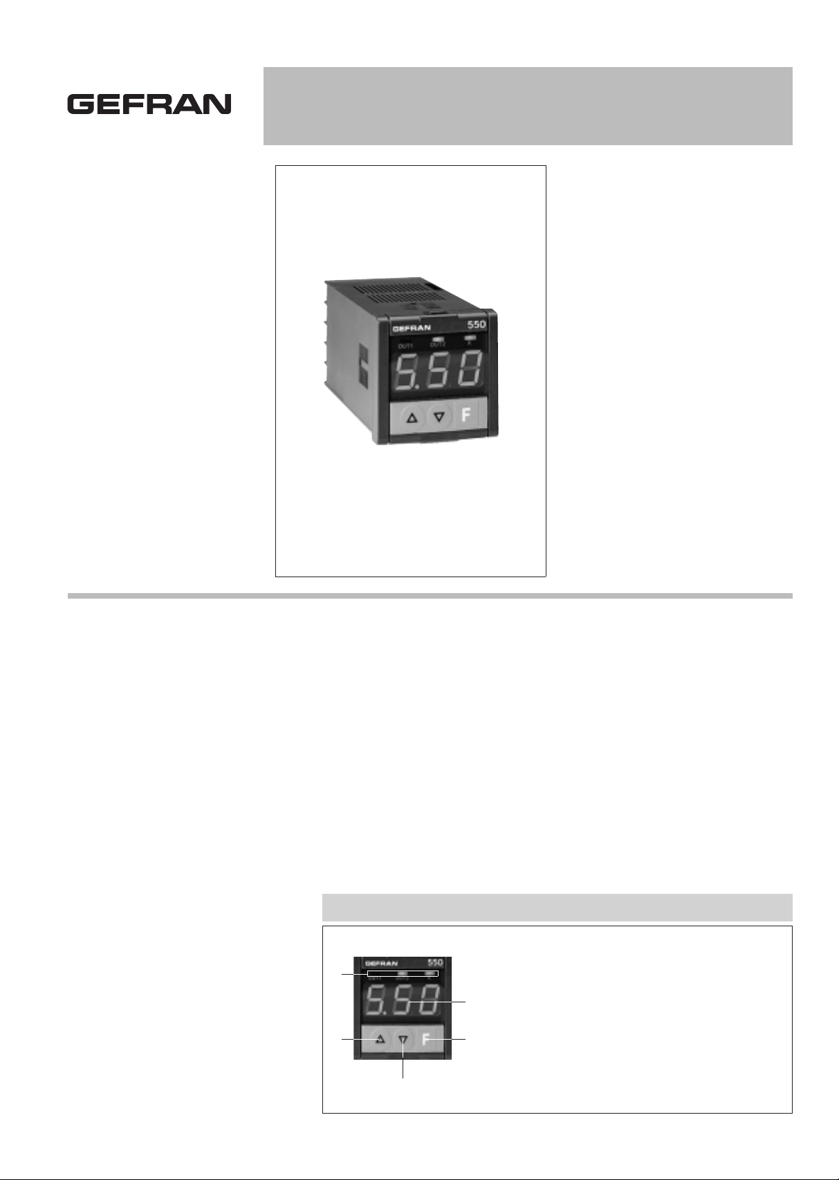
FACEPLATE DESCRIPTION
A - Main display,
digits h. 14mm, green LED
B - Function key
C - Lower key
D - Raise key
E - Output/input indication, green LED
IP54 faceplate protection
A
E
D
BC
Page 2
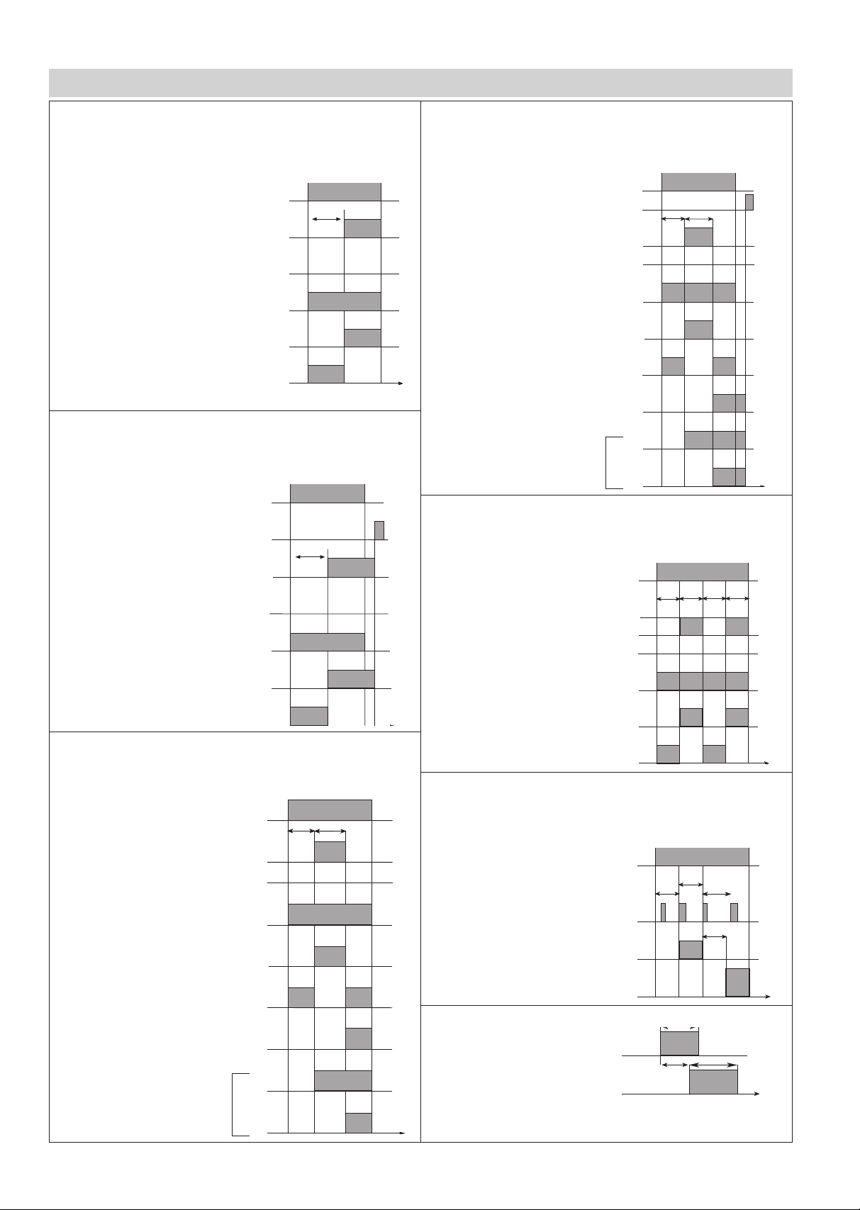
Delay timer
Relay 1 repeats the variation in the command signal on IN2 with a delay pulses time
t (=SP1). To function correctly, tk>t, where tk is
the pulse duration of the command pulse.
typ = 4
out = 9
in2 = 1
Non cyclic single timer, with reset
The timer is activated by a command on IN1.
Relay 1 energises at the end of the preset time t (=SP1) and disenergises with a
command on IN2 (reset). The action of relay 2 depends on the configuration of OUT.
typ = 0
out = 1÷4
in2 = 1
Non cyclic double timer with reset
The timing begins if there is a command signal on IN1. Relay 1 disenergises for the
preset time t1 (=SP1) and energises for the preset time t2 (=SP2). It then rests
except when the setting Out=6. To begin a new cycle, a command signal on IN2 is
required (reset). The action of relay 2 depends on the configuration of OUT.
typ = 1
out = 1÷6
in2 = 1
Non cyclic double timer without reset
The timing begins with a command signal on IN1.
Relay 1 disenergises for the preset time t1 (=SP1) and energises for the preset time
t2 (=SP2) if then rests except in the case of setting Out=6. The timer is reset by
removing the command on IN1. The action of relay 2
depends on the configuration of OUT.
typ = 1
out = 1÷6
in2 = 0
Non cyclic single timer, without reset
The timing begins with a command on IN1.
Relay 1 energises at the end of the preset time t (=SP1) and disenergises when the
command on IN1 is removed.
The action of relay 2 depends on the configuration of OUT.
typ = 0
out = 1÷4
in2 = 0
FUNCTIONALITY
(*) TMD1, TP1, TOD/TFD1, TVD1
(*) TMD4, TP4, TOD/TFD4
(*) TMD3, TP3, TOD/TFD3, TVD3
(*) TMD2, TP2, TOD/TFD2, TVD2
IN1
relay 1
relay 2
relay 2
relay 2
relay 2
not present
t
time
out=1
out=2
out=3
out=4
IN1
relay 1
relay 2
relay 2
relay 2
relay 2
not present
t
time
out=1
out=2
out=3
out=4
IN2
time
IN1
relay 1
relay 2
relay 2
relay 2
relay 2
not present
t1
out=1
out=2
out=3
out=4
t2
relay 2
relay 1
relay 2
out=6
out=5
(*) TP2-1
(*) TP2-2
(*) TP2-3
(*) TP2-4
(*) TP2-6
(*) TP2-5
time
IN1
relay 1
relay 2
relay 2
relay 2
relay 2
not present
t1
out=1
out=2
out=3
out=4
t2
relay 2
relay 1
relay 2
out=6
out=5
IN2
Double cyclic timer
The timer is activated when there is a command signal on IN1. Relay 1 remains disenergised for a preset time t1 (=SP1) and energises for a time t2 (=SP2). When time
t2 has expired, the cycle begins again at t1. It repeats the cycle continuously. The
action of relay 2 depends on the configuration of OUT.
typ = 2
out = 1÷4
in2 = 0
IN1
not present
t1 t2 t1 t2
time
relay 1
relay 2
relay 2
relay 2
relay 2
out=1
out=2
out=3
out=4
(*) TP2-S1
(*) TP2-S2
(*) TP2-S3
(*) TP2-S4
Revolution monitor
The unit becomes active when there is a command signal on IN1.
The two relays remain disenergised when the time between two pulses is between
time t1 (=SP1) and t2 (=SP2). If the time exceeds t1, relay 1 energises. If the time is
shorter than t2, relay 2 energises..
typ = 3
out = 8
in2 = 1
time
relay 1
relay 2
IN1
IN2
t<t2 t>t1
t2<t<t1
time
tk
tk
t
IN2
relay 1
Page 3

Cyclic double counter
The countdown starts at the value n1 (=SP1). When the zero is reached, the value
n2 (=SP2) begins to countdown to zero. When this count has reached zero, n1
begins to countdown once more.
Relay 1 is disenergised during the
countdown of n1 and is energised
during the countdown of n2.
typ = 14
out = see note (**)
in2 = 2
Cyclic monostable counter with block count
The countdown begins at the preset value n (=SP1) and continues down to zero.
The pulses at IN1 are counted while there is a command signal on IN2. When zero is reached,
relay 1 is energised.
The relay remains energised for a time t (=SP2),
after which the cycle starts again at the beginning.
typ = 12
out = see note (**)
(*) CP-U3
in2 = 2
Cyclic monostable counter
The countdown begins at the preset value n (=SP1) and continues down to zero.
The pulses at IN1 are countend while there is a
command signal on IN2.
When zero is reached, the counter restarts
from the beginning and relay 1 is energised.
The relay remains energised for a time t (=SP2).
typ = 11
out = see note (**)
(*) CP-U2
in2 = 2
Non cyclic monostable counter with block count
The countdown begins at the preset value n (=SP1) and continues down to zero.
The pulses at IN1 are countend while there is a command signal on IN2.
Relay 1 energises when the zero is reached and it remains energised for a time t
(=SP2). Relay 2 depends on the configuration of
OUT.
typ = 10
out = see note (**)
in2 = 2
NC
C
NO
NO/NC
C
IN2
IN1
COM
DIMENSIONS AND CUT-OUT CONNECTION DIAGRAM
Dimensions: 48x48mm (1/16 DIN), depth 100mm
!
Apply user’s manual warnings for a correct installation
59
48
70
45
45
70
48
100
10
FUNCTIONALITY
Standard counter
The countdown begins at the preset value n (=SP1), and continues down to zero.
The pulses on IN1 are counted while there is a command signal on IN2. Relay 1
energises when the count reaches zero and
disenergieses again when the command signal
on IN2 is removed. The function of relay 2
depends on the configuration of OUT.
typ = 8
out = see note (**)
(*) CP-U1
in2 = 2
time
IN2
IN1
relay 1
n
Non cyclic monostable counter
The countdown begins at the preset value n (=SP1). The pulses on IN1 are counted
while there is a command signal on IN2.
When the count reaches zero, the count continues into negative values. Relay 1 energises
when the zero is reached and remains energised for a time t (=SP2). Relay 2 depends on
the configuration of OUT.
typ = 9
out = see note (**)
in2 = 2
time
n
t
IN2
IN1
relay 1
time
n
t
IN2
IN1
relay 1
time
IN2
IN1
relay 1
nn
tt
time
IN2
IN1
relay 1
nn
tt
Non cyclic double counter
The countdown starts at the value n1 (=SP1). When the zero is reached, the value
n2 (=SP2), begins to countdown to zero, where it stops. Relay 1 is disenergised
during the countdown of n1 and is energised during the countdown of n2.
typ = 13
out = 1÷6
in2 = 2
time
IN2
relay 1
relay 2
relay 2
relay 2
relay 2
not present
n1
out=1
out=2
out=3
out=4
n2
relay 2
relay 1
relay 2
out=6
out=5
IN1
time
IN2
IN1
relay 1
n1
n2 n1 n2
PWR
SUPPLY
OUT1
(RELAY’1)
OUT2
(RELAY’2)
NOTE:
(*) Gefran instruments substituted by the model
(**) out = 1relay 2 not present, out = 2 relay 2 repeats the input command, out = 3 relay 2 repeats relay 1, out = 4 relay 2 is in opposition to relay 1
Page 4

120Vac 6
240Vac
24Vac
48Vac
3
4
5
POWER SUPPLY
24Vdc
0
ORDER CODE
GEFRAN spa reserves the right to make any kind of design or functional modification at any moment without prior notice
The instrument conforms to the European Directives 2004/108/CE and 2006/95/CE with reference to the generic standards:
EN 61000-6-2 (immunity in industrial environment) EN 61000-6-3 (emission in residential environment) EN 61010-1 (safety)
110Vac
220Vac
1
2
INPUT
From voltage free contact
C
Vac input AC
550
Please, contact GEFRAN sales people for the codes availability.
DTS_550_0509_ENG
 Loading...